EP1075984B1 - Padded seat for vehicles particularly for automotive vehicles - Google Patents
Padded seat for vehicles particularly for automotive vehicles Download PDFInfo
- Publication number
- EP1075984B1 EP1075984B1 EP00115015A EP00115015A EP1075984B1 EP 1075984 B1 EP1075984 B1 EP 1075984B1 EP 00115015 A EP00115015 A EP 00115015A EP 00115015 A EP00115015 A EP 00115015A EP 1075984 B1 EP1075984 B1 EP 1075984B1
- Authority
- EP
- European Patent Office
- Prior art keywords
- backrest
- air
- seat according
- upholstered seat
- ventilation device
- Prior art date
- Legal status (The legal status is an assumption and is not a legal conclusion. Google has not performed a legal analysis and makes no representation as to the accuracy of the status listed.)
- Expired - Lifetime
Links
Images
Classifications
-
- B—PERFORMING OPERATIONS; TRANSPORTING
- B60—VEHICLES IN GENERAL
- B60N—SEATS SPECIALLY ADAPTED FOR VEHICLES; VEHICLE PASSENGER ACCOMMODATION NOT OTHERWISE PROVIDED FOR
- B60N2/00—Seats specially adapted for vehicles; Arrangement or mounting of seats in vehicles
- B60N2/56—Heating or ventilating devices
- B60N2/5607—Heating or ventilating devices characterised by convection
- B60N2/5621—Heating or ventilating devices characterised by convection by air
- B60N2/5635—Heating or ventilating devices characterised by convection by air coming from the passenger compartment
-
- B—PERFORMING OPERATIONS; TRANSPORTING
- B60—VEHICLES IN GENERAL
- B60N—SEATS SPECIALLY ADAPTED FOR VEHICLES; VEHICLE PASSENGER ACCOMMODATION NOT OTHERWISE PROVIDED FOR
- B60N2/00—Seats specially adapted for vehicles; Arrangement or mounting of seats in vehicles
- B60N2/56—Heating or ventilating devices
- B60N2/5607—Heating or ventilating devices characterised by convection
- B60N2/5621—Heating or ventilating devices characterised by convection by air
- B60N2/5657—Heating or ventilating devices characterised by convection by air blown towards the seat surface
Definitions
- the invention relates to a seat according to the preamble of claim 1.
- the object of the present invention is the ventilation and / or air conditioning of padded To make vehicle seats easier to handle and less expensive.
- the invention provides an (active) modular ventilation and (if necessary) air conditioning unit created for vehicle seats that are characterized by a lightweight, space-saving and inexpensive Excellent design, can be easily installed and removed and is therefore simple Functional checks and (possible) repairs made possible.
- Cooling unit 13 For example a Peltier element.
- Cooling unit 13 and fan 14 form a ventilation and air conditioning device for the upholstery 11 of the (partially shown) seat back.
- the fan 14 draws outside air through a supply air duct 15 in the direction of arrow 16 (see in particular FIG. 2).
- heated - exhaust air serves an exhaust air duct 18, which is immediately next to the Supply air duct 15 and is arranged parallel to this.
- Supply and exhaust air ducts 15, 18 are like Fig. 1 reveals, on the (facing the back frame 10) inside of the back cover 12 arranged and connected to this, preferably clipped.
- the supply and exhaust air ducts 15, 18 can be customized using the thermoforming process be applied to the backrest trim part (backrest cover 12). That means, that the inlets and outlets (arrows 16, 17) of the supply and exhaust air ducts 15, 18 as required, for example following design and / or comfort conditions.
- the supply and exhaust air ducts 15, 18 are sealed for connection to the fan 14 expediently through seals that allow pressure and tolerance compensation. Foam seals are preferred for this purpose.
- a control device 19 with a electrical cable harness 20 (see in particular Fig. 2).
- the wiring harness 20 is - at 21, 22, 23 and 24 - clipped to the backrest cover 12.
- Control unit 19 is also included the backrest cover 12 connected.
- the modular backrest cover 12 / cooling and ventilation device 13 thus also include parts 15, 18, 19 and 20.
- the (detachable) connection of the modular Assembly 12 - 15, 18 - 20 with the backrest frame 10 is done by clipping or screwing. Two attachment points are indicated in the drawing and designated 25, 26.
- the cooling and ventilation device 13, 14 an air-guiding connection piece 27, which is arranged in the padding 11 or this interspersed in a recess 28.
- the connecting piece 27 leads from the fan 14 or from the cooling unit 13 to an air-permeable ventilation layer (not shown) Padding 11, from where the cooling air to an air-permeable (also not shown) Cover of the upholstery 11 arrives.
- the cooling air can flow directly into the backrest cushion 11 can be initiated, which in this case must consist of air-permeable material.
Abstract
Description
Die Erfindung bezieht sich auf einen Sitz nach dem Oberbegriff des Patentanspruchs 1.The invention relates to a seat according to the preamble of claim 1.
Es ist bekannt, Polstersitze in Kraftfahrzeugen zu belüften oder zu klimatisieren, um - insbesondere in der warmen Jahreszeit - den Fahrkomfort für die Insassen zu erhöhen. Zum diesbezüglichen Stand der Technik wird verwiesen auf DE 197 03 516 C1, DE 196 04 477 A1 und DE 196 34 370 A1.It is known to ventilate or air-condition upholstered seats in motor vehicles in order - in particular in the warm season - to increase driving comfort for the occupants. About this State of the art is referred to DE 197 03 516 C1, DE 196 04 477 A1 and DE 196 34 370 A1.
Die bekannten Maßnahmen zur Belüftung bzw. Klimatisierung von Kraftfahrzeugsitzen erfordern eine Vielzahl von Einzelteilen und -elementen, woraus - nachteiligerweise - ein entsprechender Montage- und Kostenaufwand resultiert. Auch eine Funktionsprüfung oder - eventuell erforderliche - Reparaturen an der Belüftungs- bzw. Klimati-siereinrichtung sind aufwendig und verursachen deshalb entsprechende Kosten.The known measures for ventilation or air conditioning of motor vehicle seats require a large number of individual parts and elements, from which - disadvantageously - a corresponding one Assembly and cost expenditure results. Also a functional test or - possibly Required - Repairs to the ventilation or air conditioning system are complex and therefore cause corresponding costs.
Aufgabe der vorliegenden Erfindung ist es, die Belüftung und/oder Klimatisierung von gepolsterten Fahrzeugsitzen einfacher handhabbar und kostengünstiger zu gestalten.The object of the present invention is the ventilation and / or air conditioning of padded To make vehicle seats easier to handle and less expensive.
Gemäß der Erfindung wird die Aufgabe bei einem Sitz der eingangs bezeichneten Gattung durch die kennzeichnenden Merkmale des Patentanspruchs 1 gelöst.According to the invention, the object with a seat of the type mentioned solved by the characterizing features of claim 1.
Vorteilhafte Weiterbildungen des Grundgedankens der Erfindung enthalten die Patentansprüche 2 - 17.The patent claims contain advantageous developments of the basic idea of the invention 2 - 17.
Durch die Erfindung wird eine (aktive) modulare Belüftungs- und (ggf) Klimatisierungseinheit für Fahrzeugsitze geschaffen, die sich durch eine leichte, raum-sparende und kostengünstige Bauweise auszeichnet, ohne großen Aufwand ein- und ausbaubar ist und somit auch einfache Funktionskontrollen sowie (eventuelle) Reparaturen ermöglicht. The invention provides an (active) modular ventilation and (if necessary) air conditioning unit created for vehicle seats that are characterized by a lightweight, space-saving and inexpensive Excellent design, can be easily installed and removed and is therefore simple Functional checks and (possible) repairs made possible.
Darüber hinaus werden im einzelnen folgende Vorteile erzielt:
- Funktionsintegrierte Bauteile
- Kompakte Lösung (wenig Einzelteile)
- Austauschbarkeit
- Einfache Variantensteuerung (Lehnenabdeckung mit oder ohne Belüftungs-Klimatisierungseinheit).
- Function-integrated components
- Compact solution (few parts)
- interchangeability
- Simple variant control (backrest cover with or without ventilation and air conditioning unit).
Die Erfindung ist in der Zeichnung an Hand eines Ausführungsbeispiels veranschaulicht, das nachstehend detailliert beschrieben ist. Es zeigt (jeweils teilweise dargestellt und schematisch):
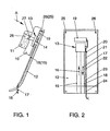
- Fig. 1
- eine Ausführungsform einer Kraftfahrzeug-Sitzlehne, in Seitenansicht, und
- Fig. 2
- die Sitzlehne nach Fig. 1, in Pfeilrichtung A betrachtet (Lehnenrahmen und Polsterauflage weggelassen).
- Fig. 1
- an embodiment of a motor vehicle seat back, in side view, and
- Fig. 2
- 1, viewed in the direction of arrow A (backrest frame and cushion cover omitted).
Es bezeichnet 10 einen Lehnenrahmen mit Polsterauflage 11. Rückseitig ist der Lehnenrahmen
10 durch eine Lehnenabdeckung 12 verkleidet. Innenseitig der Lehnenabdeckung 12
und mit dieser zu einer modularen Baueinheit verbunden ist eine Kühleinheit 13, zum Beispiel
ein Peltierelement, angeordnet. Wesentlicher Bestandteil der Kühleinheit 13 ist ein mit
14 bezifferter Ventilator. Kühleinheit 13 und Ventilator 14 bilden eine Belüftungs- und Klimati-siereinrichtung
für die Polsterung 11 der (teilweise dargestellten) Sitzlehne.It designates 10 a backrest frame with
Zur Versorgung der Kühleinheit 13 saugt der Ventilator 14 Außenluft durch einen Zuluftkanal
15 in Pfeilrichtung 16 an (siehe insbesondere Fig 2). Zur Ableitung der - durch die Kühleinheit
13 erwärmten - Abluft (Pfeilrichtung 17) dient ein Abluftkanal 18, der unmittelbar neben dem
Zuluftkanal 15 und parallel zu diesem angeordnet ist. Zu- und Abluftkanal 15, 18 sind, wie
Fig. 1 erkennen läßt, an der (dem Lehnenrahmen 10 zugewandten) Innenseite der Lehnenabdeckung
12 angeordnet und mit dieser verbunden, vorzugsweise verklipst.To supply the
Die Zu- und Abluftkanäle 15, 18 können durch Anwendung des Warmformverfahrens individuell
auf das Lehnenverkleidungsteil (Lehnenabdeckung 12) aufgebracht werden. Das bedeutet,
daß die Ein- und Austritte (Pfeile 16, 17) der Zu- und Abluftkanäle 15,18 nach Bedarf,
zum Beispiel Design- und/oder Komfortgegebenheiten folgend, verlegt werden können.The supply and
Die Abdichtung der Zu- und Abluftkanäle 15, 18 zum Anschluß am Ventilator 14 erfolgt
zweckmäßigerweise durch Dichtungen, die einen Druck- und Toleranzausgleich ermöglichen.
Hierfür sind - vorzugsweise - Schaumdichtungen geeignet.The supply and
Zur Steuerung der Kühleinheit 13 bzw. des Ventilators 14 dient ein Steuergerät 19 mit einem
elektrischen Kabelstrang 20 (siehe insbesondere Fig. 2). Der Kabelstrang 20 ist - bei 21, 22,
23 und 24 - mit der Lehnenabdeckung 12 verklipst. Ebenso ist auch das Steuergerät 19 mit
der Lehnenabdeckung 12 verbunden.To control the
Zur modularen Baueinheit Lehnenabdeckung 12 / Kühl- und Belüftungseinrichtung 13, 14
gehören somit auch die Teile 15, 18, 19 und 20. Die (lösbare) Verbindung der modularen
Baueinheit 12 - 15, 18 - 20 mit dem Lehnenrahmen 10 erfolgt durch Verklipsung oder Verschraubung.
Zwei Befestigungspunkte sind in der Zeichnung angedeutet und mit 25, 26 bezeichnet.To the
Wie des weiteren aus Fig. 1 hervorgeht, besitzt die Kühl- und Belüftungseinrichtung 13, 14
einen luftführenden Anschlußstutzen 27, der in der Polsterung 11 angeordnet ist bzw. diese
in einer Ausnehmung 28 durchsetzt. Der Anschlußstutzen 27 führt vom Ventilator 14 bzw.
von der Kühleinheit 13 zu einer (nicht dargestellten) luftdurchflutbaren Ventilationsschicht der
Polsterung 11, von wo die Kühlluft zu einem (ebenfalls nicht gezeigten) luftdurchlässigen
Bezug der Polsterung 11 gelangt.As can further be seen from FIG. 1, the cooling and
Nach einer anderen möglichen Variante kann die Kühlluft unmittelbar in das Lehnenpolster
11 eingeleitet werden, welches in diesem Fall aus luftdurchlässigem Material bestehen muß.
Bei dieser Variante ist es erforderlich, die Lehnenabdeckung 12 zusätzlich mit einer Abdichtung
(nicht gezeigt) zwischen Lehnenabdeckung 12 und Lehnenrahmen 10 zu versehen.According to another possible variant, the cooling air can flow directly into the
Claims (17)
- Upholstered seat for vehicles, in particular motor vehicles, having a ventilation device (13, 14), which is assigned to the upholstery (11) and is based on one or more fans (14) with air being sucked in, the air serving - directly or indirectly via a cooling unit (13) - for ventilating or air conditioning the upholstery (11), characterized in that the ventilation device (13, 14), which is assigned to the backrest, is arranged between the backrest upholstery (11) and a rear backrest cover (12) and forms a modular constructional unit together with the backrest cover (12).
- Upholstered seat according to Claim 1 having a backrest frame (10) holding the backrest upholstery (11), characterized in that the constructional unit of backrest cover/ventilation device (12, 13, 14) is connected releasably to the backrest frame (10).
- Upholstered seat according to Claim 2, characterized in that the constructional unit of backrest cover/ventilation device (12, 13, 14) is clipped from the inside to the backrest frame (10).
- Upholstered seat according to Claim 2, characterized in that the constructional unit of backrest cover/ventilation device (12, 13, 14) is screwed from the inside to the backrest frame (10).
- Upholstered seat according to one or more of the preceding claims, characterized in that an air-conducting connecting branch (27) is arranged in the backrest upholstery (11), the said connecting branch leading from the air outlet of the fan (14) or the cooling unit (13) to a ventilation layer through which air can flow and from which the air can pass to a covering - of air-permeable design - of the backrest upholstery (11).
- Upholstered seat according to Claim 5, characterized in that a spacer knit is used as the ventilation layer through which air can flow.
- Upholstered seat according to one or more of Claims 1-4 and 6, characterized in that the air which is conveyed by the fan (14) or by the cooling unit (13) passes directly into the backrest upholstery (11) - which, for this purpose, is of air-permeable design in its entirety - and from there to the air-permeable upholstery covering.
- Upholstered seat according to Claim 7, characterized in that the backrest cover (12) is sealed off from the backrest frame (10).
- Upholstered seat according to one or more of the preceding Claims, characterized in that the constructional unit of backrest cover/ventilation device (12, 14) has one or more fans (14) which are connected to air inlet ducts (15) which are likewise integrated in the constructional unit of backrest covers/ventilation device (12, 14).
- Upholstered seat according to one or more of Claims 1 to 8, characterized in that the constructional unit of backrest cover/ventilation device (12, 13) contains one or more cooling elements (13), and in that the cooling element(s) (13) is (are) connected to outlet air ducts (18) which are likewise integrated in the constructional unit of backrest cover/ventilation device (12, 13).
- Upholstered seat according to Claim 9 or 10, characterized in that the inlet air and outlet air ducts (15, 18) are arranged parallel to one another and essentially also to the plane formed by the backrest (10, 11, 12) and are arranged next to one another, and in that the inlet air and outlet air ducts (15, 18) run from the bottom upwards or from the top downwards in such a manner that - in each case at the lower end of the backrest cover (12) - the incoming air passes into the inlet air duct (15) (arrow 16) and the outgoing air emerges from outlet air duct (18) (arrow 17).
- Upholstered seat according to Claim 9, 10 or 11, characterized in that the inlet air and outlet air ducts (15, 18) are arranged on the inside of the backrest cover (12) and are connected to the latter.
- Upholstered seat according to Claim 9, characterized in that the inlet air ducts (15) are sealed off with respect to the respective connection on the fan (14) by means of seals, preferably foam seals, permitting equalization of pressure and compensation for tolerances.
- Upholstered seat according to one or more of the preceding claims, having a control unit (19) for the cooling element (13) and the ventilation device (13, 14), characterized in that the control unit (19), including electric cabling (20) provided for this purpose, is arranged and fixed on the inside of the backrest cover (12) in such a manner that it forms an integrated component of the constructional unit of backrest cover/ventilation device (12, 13, 14).
- Upholstered seat according to one or more of the preceding claims, characterized in that the fan(s) (14) is (are) isolated from the backrest cover (12) for the purpose of eliminating noise and vibration.
- Upholstered seat according to Claim 15, characterized in that an inherent isolation of the fan (of the fans) (14) is provided.
- Upholstered seat according to Claim 15, characterized in that the fan(s) (14) is (are) decoupled from the backrest cover (12) by means of isolating elements which are arranged at the transitional region between fan(s) (14) and backrest cover (12).
Applications Claiming Priority (2)
| Application Number | Priority Date | Filing Date | Title |
|---|---|---|---|
| DE19937464A DE19937464A1 (en) | 1999-08-07 | 1999-08-07 | Upholstered seat for vehicles, in particular motor vehicles |
| DE19937464 | 1999-08-07 |
Publications (3)
| Publication Number | Publication Date |
|---|---|
| EP1075984A2 EP1075984A2 (en) | 2001-02-14 |
| EP1075984A3 EP1075984A3 (en) | 2002-01-16 |
| EP1075984B1 true EP1075984B1 (en) | 2003-05-07 |
Family
ID=7917669
Family Applications (1)
| Application Number | Title | Priority Date | Filing Date |
|---|---|---|---|
| EP00115015A Expired - Lifetime EP1075984B1 (en) | 1999-08-07 | 2000-07-24 | Padded seat for vehicles particularly for automotive vehicles |
Country Status (3)
| Country | Link |
|---|---|
| EP (1) | EP1075984B1 (en) |
| AT (1) | ATE239627T1 (en) |
| DE (2) | DE19937464A1 (en) |
Cited By (10)
| Publication number | Priority date | Publication date | Assignee | Title |
|---|---|---|---|---|
| US7735932B2 (en) | 2005-08-19 | 2010-06-15 | W.E.T. Automotive Systems Ag | Automotive vehicle seat insert |
| US7781704B2 (en) | 2003-09-25 | 2010-08-24 | W.E.T. Automotive Systems Ag | Control system for operating automotive vehicle components |
| US7918498B2 (en) | 2003-12-01 | 2011-04-05 | W.E.T. Automotive Systems Ag | Valve layer for a seat |
| US8167368B2 (en) | 2009-02-18 | 2012-05-01 | W.E.T. Automotive System Ag | Air conditioning device for vehicle seats |
| US8777320B2 (en) | 2008-12-21 | 2014-07-15 | W.E.T. Automotive Systems Ag | Ventilation system |
| US20150183348A1 (en) * | 2013-12-26 | 2015-07-02 | Gentherm Automotive Systems (China) Ltd. | Heating fan, in particular for use as a neck warmer in vehicle seats |
| US9333888B2 (en) | 2012-07-25 | 2016-05-10 | Gentherm Gmbh | Heater fan, especially for use as a neck warmer in vehicle seats |
| US10625643B2 (en) | 2017-06-14 | 2020-04-21 | Gentherm Gmbh | Conditioning system with blower attachment system and method of attachment |
| US10926677B2 (en) | 2015-12-14 | 2021-02-23 | Gentherm Gmbh | Neck fan for a vehicle seat and control method therefor |
| US10933780B2 (en) | 2016-02-10 | 2021-03-02 | Gentherm Gmbh | Device for controlling the temperature of the neck region of a user of a vehicle seat |
Families Citing this family (4)
| Publication number | Priority date | Publication date | Assignee | Title |
|---|---|---|---|---|
| US6629724B2 (en) | 2001-01-05 | 2003-10-07 | Johnson Controls Technology Company | Ventilated seat |
| DE10316732B4 (en) * | 2003-04-08 | 2013-10-02 | Volkswagen Ag | Method and device for controlling air conditioning / ventilation seats depending on the seat and vehicle interior temperature |
| DE102004057640B4 (en) * | 2004-11-30 | 2011-05-26 | Daimler Ag | Air supply device for a vehicle seat of a motor vehicle |
| DE102009030491A1 (en) | 2009-03-18 | 2010-09-23 | W.E.T. Automotive Systems Ag | Air conditioning device for an air-conditioned object in a vehicle interior |
Family Cites Families (11)
| Publication number | Priority date | Publication date | Assignee | Title |
|---|---|---|---|---|
| DE4112631C1 (en) * | 1991-04-18 | 1992-04-30 | Keiper Recaro Gmbh & Co, 5630 Remscheid, De | Motor vehicle seat with moisture removal inset - incorporating air channel at rear of backrest with air dryer |
| DE19604477A1 (en) * | 1996-02-08 | 1997-08-14 | Teves Gmbh Alfred | Cooling device for motor vehicle seats |
| DE19628698C1 (en) * | 1996-07-17 | 1997-10-09 | Daimler Benz Ag | Ventilated seat for use in vehicle |
| DE19634370C2 (en) * | 1996-08-26 | 2000-04-27 | Daimler Chrysler Ag | Vehicle seat |
| DE19703516C1 (en) * | 1997-01-31 | 1998-05-07 | Daimler Benz Ag | Vehicle seat with upholstery heating and cooling |
| DE19830797B4 (en) * | 1997-07-14 | 2007-10-04 | Denso Corp., Kariya | Vehicle seat air conditioner |
| DE19737636A1 (en) * | 1997-08-28 | 1999-03-11 | Aisin Seiki | Climate-controlled for vehicle seats or bed |
| DE19805174C1 (en) * | 1998-02-10 | 1999-06-02 | Daimler Chrysler Ag | Motor vehicle heated seat with seat and backrest cushions containing air passages and electric fans |
| DE19805173C1 (en) * | 1998-02-10 | 1999-06-02 | Daimler Chrysler Ag | Motor vehicle seat with ventilation |
| DE19851979C2 (en) * | 1998-11-11 | 2000-08-31 | Daimler Chrysler Ag | Temperature sensor for an air-conditioned vehicle seat |
| DE19920062C2 (en) * | 1999-05-03 | 2003-11-06 | Daimler Chrysler Ag | vehicle seat |
-
1999
- 1999-08-07 DE DE19937464A patent/DE19937464A1/en not_active Withdrawn
-
2000
- 2000-07-24 AT AT00115015T patent/ATE239627T1/en not_active IP Right Cessation
- 2000-07-24 DE DE50002048T patent/DE50002048D1/en not_active Expired - Lifetime
- 2000-07-24 EP EP00115015A patent/EP1075984B1/en not_active Expired - Lifetime
Cited By (20)
| Publication number | Priority date | Publication date | Assignee | Title |
|---|---|---|---|---|
| US7781704B2 (en) | 2003-09-25 | 2010-08-24 | W.E.T. Automotive Systems Ag | Control system for operating automotive vehicle components |
| US8309892B2 (en) | 2003-09-25 | 2012-11-13 | W.E.T. Automotive System, Ltd | Control system for operating automotive vehicle components |
| US7918498B2 (en) | 2003-12-01 | 2011-04-05 | W.E.T. Automotive Systems Ag | Valve layer for a seat |
| US8235462B2 (en) | 2003-12-01 | 2012-08-07 | W.E.T. Automotive Systems, Ltd. | Valve layer for a seat |
| US7971931B2 (en) | 2005-08-19 | 2011-07-05 | W.E.T. Automotive Systems Ag | Automotive vehicle seat insert |
| US8162391B2 (en) | 2005-08-19 | 2012-04-24 | W.E.T. Automotive Systems Ag | Automotive vehicle seat insert |
| US8360517B2 (en) | 2005-08-19 | 2013-01-29 | W.E.T. Automotive Systems, Ag. | Automotive vehicle seat insert |
| US7735932B2 (en) | 2005-08-19 | 2010-06-15 | W.E.T. Automotive Systems Ag | Automotive vehicle seat insert |
| US9440567B2 (en) | 2005-08-19 | 2016-09-13 | Gentherm Gmbh | Automotive vehicle seat insert |
| US9415712B2 (en) | 2008-12-21 | 2016-08-16 | Gentherm Gmbh | Ventilation system |
| US8777320B2 (en) | 2008-12-21 | 2014-07-15 | W.E.T. Automotive Systems Ag | Ventilation system |
| US8167368B2 (en) | 2009-02-18 | 2012-05-01 | W.E.T. Automotive System Ag | Air conditioning device for vehicle seats |
| US10118517B2 (en) | 2012-07-25 | 2018-11-06 | Gentherm Gmbh | Heater fan, especially for use as a neck warmer in vehicle seats |
| US9333888B2 (en) | 2012-07-25 | 2016-05-10 | Gentherm Gmbh | Heater fan, especially for use as a neck warmer in vehicle seats |
| US9346384B2 (en) * | 2013-12-26 | 2016-05-24 | Gentherm Automotive Systems (China) Ltd. | Heating fan, in particular for use as a neck warmer in vehicle seats |
| US20150183348A1 (en) * | 2013-12-26 | 2015-07-02 | Gentherm Automotive Systems (China) Ltd. | Heating fan, in particular for use as a neck warmer in vehicle seats |
| US10926677B2 (en) | 2015-12-14 | 2021-02-23 | Gentherm Gmbh | Neck fan for a vehicle seat and control method therefor |
| US10933780B2 (en) | 2016-02-10 | 2021-03-02 | Gentherm Gmbh | Device for controlling the temperature of the neck region of a user of a vehicle seat |
| US10625643B2 (en) | 2017-06-14 | 2020-04-21 | Gentherm Gmbh | Conditioning system with blower attachment system and method of attachment |
| US10710480B2 (en) | 2017-06-14 | 2020-07-14 | Gentherm Gmbh | Conditioning system with blower connection assembly including a distribution member and method of attachment |
Also Published As
| Publication number | Publication date |
|---|---|
| DE19937464A1 (en) | 2001-02-08 |
| EP1075984A3 (en) | 2002-01-16 |
| EP1075984A2 (en) | 2001-02-14 |
| ATE239627T1 (en) | 2003-05-15 |
| DE50002048D1 (en) | 2003-06-12 |
Similar Documents
| Publication | Publication Date | Title |
|---|---|---|
| EP1075984B1 (en) | Padded seat for vehicles particularly for automotive vehicles | |
| DE102004005573B4 (en) | vehicle seat | |
| DE19805173C1 (en) | Motor vehicle seat with ventilation | |
| DE102015225517B4 (en) | Seating arrangement operatively connected to an HVAC device | |
| DE10207489B4 (en) | Automotive seat | |
| EP1600375B1 (en) | Seat, especially aircraft passenger seat | |
| EP0933247A2 (en) | Ventilated vehicle seat | |
| EP1266794A2 (en) | Vehicle seat with seat ventilation | |
| EP1203691A2 (en) | Automotive vehicle seat with air supply installation | |
| EP1479918A1 (en) | Blower for a motor vehicle seat | |
| DE102012006074A1 (en) | Motor vehicle seat for motor vehicle, has surface, particularly seat- and rest surface facing vehicle occupant, and blower, where air intake and air discharge exclusively takes place over surface facing vehicle occupant | |
| EP0028370A1 (en) | Motor vehicle with an additional mirror eliminating "blind spots" | |
| DE102016117443A1 (en) | Seat with a ventilation device and method for air conditioning the seating environment | |
| DE102018222502A1 (en) | Ventilation system for a locally adjustable temperature zone in a passenger compartment | |
| DE7731774U1 (en) | Air-conditioned passenger vehicle, preferably with a partition between the front part of the passenger compartment and the rear compartment | |
| DE102008048743A1 (en) | Integrated air supply device | |
| EP0846580A3 (en) | Vehicle independent heating and ventilation device for a vehicle, particularly for passenger cars | |
| DE102011114933B4 (en) | "Seat frame for a vehicle seat" | |
| DE102008063666A1 (en) | Head-rest heater for heating e.g. neck region of passenger in seat of e.g. cabriolet, has Infrared radiators generating infrared-heat provided as infrared radiators generating desired heat, where infrared-heat acts independent of air flow | |
| DE102010010476A1 (en) | Air conditioning system for seat of motor vehicle, has heating device provided for heating air, and seat ventilating device provided to aerate pad of vehicle seat, and air flows out from outflow opening along main flow direction | |
| DE19742566C1 (en) | Air separator for motor vehicle interior | |
| DE10349410A1 (en) | Air conditioning device for vehicle interior components has ventilation device in support feeding cooled air into or heated air out of interior, coating transmissive to air, distancing arrangement | |
| DE102015213299A1 (en) | Passenger car with ventilated rear foot room | |
| WO2000026047A1 (en) | Ventilation device for vehicles | |
| DE102013221000A1 (en) | Air-conditioned seat for vehicle i.e. motor car, has air circulation layer whose top face covers air-permeable cushion layer, and air-permeable cover covering cushion layer that is provided in air stream channel |
Legal Events
| Date | Code | Title | Description |
|---|---|---|---|
| PUAI | Public reference made under article 153(3) epc to a published international application that has entered the european phase |
Free format text: ORIGINAL CODE: 0009012 |
|
| AK | Designated contracting states |
Kind code of ref document: A2 Designated state(s): AT BE CH CY DE DK ES FI FR GB GR IE IT LI LU MC NL PT SE |
|
| AX | Request for extension of the european patent |
Free format text: AL;LT;LV;MK;RO;SI |
|
| PUAL | Search report despatched |
Free format text: ORIGINAL CODE: 0009013 |
|
| AK | Designated contracting states |
Kind code of ref document: A3 Designated state(s): AT BE CH CY DE DK ES FI FR GB GR IE IT LI LU MC NL PT SE |
|
| AX | Request for extension of the european patent |
Free format text: AL;LT;LV;MK;RO;SI |
|
| 17P | Request for examination filed |
Effective date: 20020716 |
|
| AKX | Designation fees paid |
Free format text: AT BE CH CY DE DK ES FI FR GB GR IE IT LI LU MC NL PT SE |
|
| GRAH | Despatch of communication of intention to grant a patent |
Free format text: ORIGINAL CODE: EPIDOS IGRA |
|
| GRAH | Despatch of communication of intention to grant a patent |
Free format text: ORIGINAL CODE: EPIDOS IGRA |
|
| GRAA | (expected) grant |
Free format text: ORIGINAL CODE: 0009210 |
|
| AK | Designated contracting states |
Designated state(s): AT BE CH CY DE DK ES FI FR GB GR IE IT LI LU MC NL PT SE |
|
| PG25 | Lapsed in a contracting state [announced via postgrant information from national office to epo] |
Ref country code: IT Free format text: LAPSE BECAUSE OF FAILURE TO SUBMIT A TRANSLATION OF THE DESCRIPTION OR TO PAY THE FEE WITHIN THE PRESCRIBED TIME-LIMIT;WARNING: LAPSES OF ITALIAN PATENTS WITH EFFECTIVE DATE BEFORE 2007 MAY HAVE OCCURRED AT ANY TIME BEFORE 2007. THE CORRECT EFFECTIVE DATE MAY BE DIFFERENT FROM THE ONE RECORDED. Effective date: 20030507 Ref country code: GB Free format text: LAPSE BECAUSE OF FAILURE TO SUBMIT A TRANSLATION OF THE DESCRIPTION OR TO PAY THE FEE WITHIN THE PRESCRIBED TIME-LIMIT Effective date: 20030507 Ref country code: IE Free format text: LAPSE BECAUSE OF NON-PAYMENT OF DUE FEES Effective date: 20030507 Ref country code: NL Free format text: LAPSE BECAUSE OF FAILURE TO SUBMIT A TRANSLATION OF THE DESCRIPTION OR TO PAY THE FEE WITHIN THE PRESCRIBED TIME-LIMIT Effective date: 20030507 Ref country code: FI Free format text: LAPSE BECAUSE OF FAILURE TO SUBMIT A TRANSLATION OF THE DESCRIPTION OR TO PAY THE FEE WITHIN THE PRESCRIBED TIME-LIMIT Effective date: 20030507 |
|
| REG | Reference to a national code |
Ref country code: GB Ref legal event code: FG4D Free format text: NOT ENGLISH |
|
| REG | Reference to a national code |
Ref country code: CH Ref legal event code: EP |
|
| REG | Reference to a national code |
Ref country code: IE Ref legal event code: FG4D Free format text: GERMAN |
|
| REF | Corresponds to: |
Ref document number: 50002048 Country of ref document: DE Date of ref document: 20030612 Kind code of ref document: P |
|
| PG25 | Lapsed in a contracting state [announced via postgrant information from national office to epo] |
Ref country code: CY Free format text: LAPSE BECAUSE OF FAILURE TO SUBMIT A TRANSLATION OF THE DESCRIPTION OR TO PAY THE FEE WITHIN THE PRESCRIBED TIME-LIMIT Effective date: 20030724 Ref country code: LU Free format text: LAPSE BECAUSE OF NON-PAYMENT OF DUE FEES Effective date: 20030724 Ref country code: AT Free format text: LAPSE BECAUSE OF NON-PAYMENT OF DUE FEES Effective date: 20030724 |
|
| PG25 | Lapsed in a contracting state [announced via postgrant information from national office to epo] |
Ref country code: BE Free format text: LAPSE BECAUSE OF NON-PAYMENT OF DUE FEES Effective date: 20030731 Ref country code: MC Free format text: LAPSE BECAUSE OF NON-PAYMENT OF DUE FEES Effective date: 20030731 |
|
| PG25 | Lapsed in a contracting state [announced via postgrant information from national office to epo] |
Ref country code: SE Free format text: LAPSE BECAUSE OF FAILURE TO SUBMIT A TRANSLATION OF THE DESCRIPTION OR TO PAY THE FEE WITHIN THE PRESCRIBED TIME-LIMIT Effective date: 20030807 Ref country code: GR Free format text: LAPSE BECAUSE OF FAILURE TO SUBMIT A TRANSLATION OF THE DESCRIPTION OR TO PAY THE FEE WITHIN THE PRESCRIBED TIME-LIMIT Effective date: 20030807 Ref country code: PT Free format text: LAPSE BECAUSE OF FAILURE TO SUBMIT A TRANSLATION OF THE DESCRIPTION OR TO PAY THE FEE WITHIN THE PRESCRIBED TIME-LIMIT Effective date: 20030807 Ref country code: DK Free format text: LAPSE BECAUSE OF FAILURE TO SUBMIT A TRANSLATION OF THE DESCRIPTION OR TO PAY THE FEE WITHIN THE PRESCRIBED TIME-LIMIT Effective date: 20030807 |
|
| PG25 | Lapsed in a contracting state [announced via postgrant information from national office to epo] |
Ref country code: ES Free format text: LAPSE BECAUSE OF FAILURE TO SUBMIT A TRANSLATION OF THE DESCRIPTION OR TO PAY THE FEE WITHIN THE PRESCRIBED TIME-LIMIT Effective date: 20030818 |
|
| NLV1 | Nl: lapsed or annulled due to failure to fulfill the requirements of art. 29p and 29m of the patents act | ||
| GBV | Gb: ep patent (uk) treated as always having been void in accordance with gb section 77(7)/1977 [no translation filed] |
Effective date: 20030507 |
|
| ET | Fr: translation filed | ||
| REG | Reference to a national code |
Ref country code: IE Ref legal event code: FD4D Ref document number: 1075984E Country of ref document: IE |
|
| BERE | Be: lapsed |
Owner name: *VOLKSWAGEN A.G. Effective date: 20030731 |
|
| PLBE | No opposition filed within time limit |
Free format text: ORIGINAL CODE: 0009261 |
|
| STAA | Information on the status of an ep patent application or granted ep patent |
Free format text: STATUS: NO OPPOSITION FILED WITHIN TIME LIMIT |
|
| 26N | No opposition filed |
Effective date: 20040210 |
|
| PG25 | Lapsed in a contracting state [announced via postgrant information from national office to epo] |
Ref country code: LI Free format text: LAPSE BECAUSE OF NON-PAYMENT OF DUE FEES Effective date: 20040731 Ref country code: CH Free format text: LAPSE BECAUSE OF NON-PAYMENT OF DUE FEES Effective date: 20040731 |
|
| REG | Reference to a national code |
Ref country code: CH Ref legal event code: PL |
|
| REG | Reference to a national code |
Ref country code: FR Ref legal event code: PLFP Year of fee payment: 16 |
|
| REG | Reference to a national code |
Ref country code: FR Ref legal event code: PLFP Year of fee payment: 17 |
|
| PGFP | Annual fee paid to national office [announced via postgrant information from national office to epo] |
Ref country code: DE Payment date: 20160731 Year of fee payment: 17 |
|
| PGFP | Annual fee paid to national office [announced via postgrant information from national office to epo] |
Ref country code: FR Payment date: 20160728 Year of fee payment: 17 |
|
| REG | Reference to a national code |
Ref country code: DE Ref legal event code: R079 Ref document number: 50002048 Country of ref document: DE Free format text: PREVIOUS MAIN CLASS: B60N0002440000 Ipc: B60N0002900000 |
|
| REG | Reference to a national code |
Ref country code: DE Ref legal event code: R119 Ref document number: 50002048 Country of ref document: DE |
|
| REG | Reference to a national code |
Ref country code: FR Ref legal event code: ST Effective date: 20180330 |
|
| PG25 | Lapsed in a contracting state [announced via postgrant information from national office to epo] |
Ref country code: DE Free format text: LAPSE BECAUSE OF NON-PAYMENT OF DUE FEES Effective date: 20180201 |
|
| PG25 | Lapsed in a contracting state [announced via postgrant information from national office to epo] |
Ref country code: FR Free format text: LAPSE BECAUSE OF NON-PAYMENT OF DUE FEES Effective date: 20170731 |