BACKGROUND OF THE INVENTION
The present invention relates to a train-control system,
and especially to an automatic train-control system or an
automatic train-operation system.
Railway transportation is a transportation form in
which a plurality of trains run on a railway where the degree
of freedom in motion is restricted. However, to respond to
needs for reinforcement of transportation capacity, or for
manifold traffic-flow modes, a more complicated running
system, which makes it possible to frequently change and set
running plans of respective plural trains, corresponding to
manifold stop-patterns, has recently been required. In order
to achieve such a complicated running system, what is called
a coupling/dividing method has been examined for its
practicality. In the coupling/dividing method, the limited
transportation capacity of the railway can be improved by
coupling a plurality of trains, and operate those coupled
trains as if these were one train, operating in a divided
interval in a railway, where the plurality of trains to which
various originating and terminating stations are allocated,
are planned to be run. Further, in other railway intervals,
the virtual single train is separated into respective
individual trains, according to their terminating stations.
Also, in railway transportation, an automatic control
system (a train-control system) has been introduced to
operate trains safely and efficiently. An automatic
train-control system (ATC) which restricts the speed of a
succeeding train corresponding to the current position of;
or the open/closed state of a way ahead of a preceding train,
is used. Further, an automatic train-operation system (ATO)
which performs a series of operations of a train, from
starting from the originating station to arriving at the
terminating station, is also used.
First, the coupling/dividing method used for
conventional train-control systems is explained below. In
the conventional train-control systems, a mounted control
unit for outputting control-commands to control the running
of a train, is provided in each rolling-stock set, which is
a unit set, with which the coupling/dividing method is
implemented. A drive unit, which outputs drive force for a
rolling-stock set, is mounted in each rolling-stock set, and
operates according to a control command sent from the mounted
control unit.
During the dividing operation mode in the above
train-control system, each rolling-stock set is
independently operated as one train. Accordingly, the
mounted control unit of each train operates separately, in
each rolling-stock set, and controls the running of each train
consisting of a single rolling-stock set.
On the other hand, during the coupling operation mode,
a group of coupled plural rolling-stock sets is operated as
if they were a single train. That is, the running of a train
composed of a plurality of rolling-stock sets is controlled
in a lot. In this control, although there is a plurality of
mounted control units located in the respective rolling-stock
sets in the train, only one of the mounted control units
is used, and the other ones are not used.
Usually, in the conventional coupling operations, one
of the mounted control units in the train composed of a
plurality of coupled rolling-stock sets, controls not only
its own rolling-stock set, but also the other ones as
mentioned above. Such a control method is generally called
an integrated control.
Further, in the conventional integrated control method,
it is assumed that if a train is composed of a plurality of
rolling-stock sets, the type of all the plurality of
rolling-stock sets is the same, or a specific combination
of types of sets, is used for the train. Furthermore, as per
the content (indicated by the number of notches) of a control
command, sent from the mounted control unit for controlling
the running of the train as a whole (referred to as the whole
train), the same notch number is allocated to all the
rolling-stock sets.
Moreover, in the above conventional control methods,
the same driving performance is allocated to each
rolling-stock set of a specific combination of types of sets
in the coupling operation mode, in addition to a proper
driving performance of each set in the dividing operation
mode, and the operation mode is switched between the coupling
and dividing operation modes. This control method is called
a co-operation control.
Conventional techniques of the above integrated or
co-operation control are disclosed, for example; in a paper
titled "Development of Integrated Control Operation Systems
for EC/DC", the proceedings of the 34th national symposium
on application of cybernetics to the railway transportation,
pp 512, the Council of Cybernetics-Application in the
Japanese Railway Transportation; or in Japanese Patent
Application Laid-Open Hei 7-115711.
However, there are the following problems in the above
conventional integrated-control for a train-control system.
First, since the above integrated-control is
restricted to a train composed of the same-type rolling-stock
sets, or a train consisting of a predetermined
combination of types of rolling-stock sets, implementing the
coupling/dividing operation modes is limited by the types
of rolling-stock sets used in the railway transportation
system.
Further, in the case where a train is composed of
different-type rolling-stock sets, that is, rolling-stocks
with different performances, the above integrated control
does not take the performance of the whole train into
consideration. This is a problem in realizing a single-step-braking
train-protection control, typical of the
next-generation TACs, capable of corresponding to a train
composed of manifold-type rolling-stock sets. Also,
consideration of the performance of the whole train composed
of manifold-type rolling-stock sets, is indispensable in
realizing an ATC system which should momentarily perform a
running-control of the train, in all intervals among the
stations for the train.
Furthermore, in the conventional techniques, a control
command, indicated with the same number of notches, sent from
the mounted control unit for controlling a train, to all
rolling-stock sets in a train. However, the acceleration/deceleration
generated in response to the same notch number
in powering/braking, is different in respective rolling-stock
sets with different running-performances, composing
the train as a whole. Accordingly, the above conventional
integrated-control generates unnatural force between the
rolling-stock sets, which in turn may cause strength
degradation, due to fatigue, and defacement of a
rolling-stock set-coupling unit for coupling the
rolling-stock sets of the train.
Thus, to control the whole train appropriately, it is
newly required that the running-performance of the train as
a whole be considered, and the train is controlled as such ,
recognizing the manifold composition-state of the train,
that is, whether the running is performed in the coupling
or dividing operation mode, and/or recognizing what types
and number of rolling-stock sets compose the train in the
coupling operation mode.
Moreover, it is also newly required that a control
command for each rolling-stock set is sent, corresponding
to the manifold composition-state of the train, to optimize
the driving state of the respective rolling-stock sets in
the train.
SUMMARY OF THE INVENTION
An objective of the present invention is to provide
a train-control system which can optimize the operation of
a train by recognizing the running-performance of the whole
train, and the driving states of respective rolling-stock
sets composing the train, and realizing a running-control
to adaptively control the train, for all the assumed
combinations of the types and number of the rolling-stock
sets, in the train-operation in which the coupling or dividing
operation mode is executed.
To solve the above problems, the present invention
provides the following functions in a train-control system.
One of the main functions is to generate information on the
running-performance of the whole train by using running-performances
of respective rolling-stock sets which compose
the train.
Another main function is to generate control-commands
for controlling the running of each rolling-stock set by using
a control command for controlling the running of a train as
a whole.
To realize the above functions, a train-control system
according to the present invention has the following
composition.
A first train-control system comprises:
Further, the above integrated rolling-stock set-control
apparatus includes:
A second train-control system comprises:
Further, the above integrated rolling-stock set-control
apparatus includes:
A third train-control system comprises:
Further, the above integrated rolling-stock set-control
unit includes:
Also, the above integrated rolling-stock set control
unit includes:
Further, the above integrated rolling-stock set-connection
device included in the integrated rolling-stock
set control unit includes:
Also, the above integrated rolling-stock set control
unit includes:
Further, the above integrated rolling-stock set-connection
device provided in the integrated rolling-stock
set control unit includes:
Further, the above means for generating control-commands
for the respective rolling-stock sets generates the
respective control-commands so as to reduce the combined
quantity of interactive force acting between the
rolling-stock sets.
BRIEF DESCRIPTION OF THE DRAWINGS
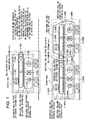
Fig. 1 is a diagram showing a schematic composition
of a train-control system of an embodiment 1 according to
the present invention.
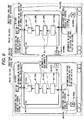
Fig. 2 is a diagram showing an information flow in an
integrated rolling-stock set-control system in the
embodiment 1 in the case where the rolling-stock sets are
operated in the dividing operation mode.
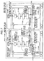
Fig. 3 is a diagram showing an information flow in an
integrated rolling-stock set-control system in the
embodiment 1 in the case where the rolling-stock sets are
operated in the coupling operation mode.
Fig. 4 is a diagram showing the functional composition
of an integrated rolling-stock set-connection device in an
embodiment 2 according to the present invention.
Fig. 5 is a flow chart showing processing executed by
the integrated rolling-stock set-connection device in an
embodiment 2 according to the present invention.
Fig. 6 is a diagram showing an information flow in an
integrated rolling-stock set-control system in the
embodiment 2 in the case where the rolling-stock sets are
operated in the dividing operation mode.
Fig. 7 is a diagram showing an information flow in an
integrated rolling-stock set-control system in the
embodiment 2 in the case where the rolling-stock sets are
operated in the coupling operation mode.
Fig. 8 is a diagram showing the functional composition
of a means for generating information on the performance of
the whole train in the embodiment 2 according to the present
invention.
Fig. 9 is a flow chart of processing executed by the
means for generating information on the performance of the
whole train in the embodiment 2 according to the present
invention.
Fig. 10 is an illustration conceptually showing a
compound performance of the whole train in which
rolling-stock sets with different running-performances are
coupled.
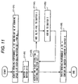
Fig. 11 is a flow chart showing a process of generating
a braking performance βtrain(V) at an assumed speed V, which
is executed by a means for generating the compounded
braking-performance of the whole train, in the embodiment
2 according to the present invention.
Fig. 12 is a diagram showing input information and
output information, which are expressed in Tables, in the
process shown in Fig. 11, in the case where the train is
composed of rolling-stock sets A and B, with different
running-performances.
Fig. 13 is an illustration conceptually showing the
compounded braking-performance with respect to speed,
obtained by the process shown in Fig. 12 in the case where
the train is composed of rolling-stock sets A and B, with
different running-performances.
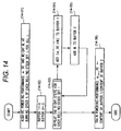
Fig. 14 is a flow chart showing a process of generating
a powering performance αtrain(V) at an assumed speed V, which
is executed by a means for generating the compounded
powering-performance of the whole train, in the embodiment
2 according to the present invention.
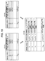
Fig. 15 is a diagram showing input information and
output information, which are expressed in Tables, in the
flow chart shown in Fig. 14, in the case where the train is
composed of rolling-stock sets A and B, with different
running-performances.
Fig. 16 is an illustration conceptually showing the
compounded powering-performance with respect to speed,
obtained by the flow chart shown in Fig. 14 in the case where
the train is composed of rolling-stock sets A and B, with
different running-performances.
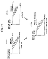
Fig. 17 is an illustration conceptually showing the
compounded powering-performance with respect to speed,
obtained by the flow chart shown in Fig. 14, which is executed
in an embodiment 3, in the case where the train is composed
of rolling-stock, sets A and B, with different running-performances.
Fig. 18 is a diagram showing the functional composition
of an integrated rolling-stock set-connection device in an
embodiment 4 according to the present invention.
Fig. 19 is a flow chart showing processing executed
by the integrated rolling-stock set-connection device in the
embodiment 4 according to the present invention.
Fig. 20 is a diagram showing an information flow in
an integrated rolling-stock set-control system in the
embodiment 4 in the case where the rolling-stock sets are
operated in the dividing operation mode.
Fig. 21 is a diagram showing an information flow in
an integrated rolling-stock set-control system in the
embodiment 4 in the case where the rolling-stock sets are
operated in the coupling operation mode.
Fig. 22 is a diagram showing the functional composition
of a means for generating control-commands for individual
rolling-stock sets in the embodiment 4 according to the
present invention.
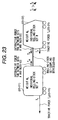
Fig. 23 is an illustration conceptually showing an
example of respective force acting between rolling-stock
sets composing the whole train in which rolling-stock sets
with different running-performances are coupled.
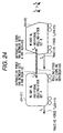
Fig. 24 is an illustration conceptually showing another
example of respective force acting between rolling-stock
sets composing the whole train in which rolling-stock sets
with different running-performances are coupled.
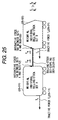
Fig. 25 is an illustration conceptually showing another
example of respective force acting between rolling-stock
sets composing the whole train in which rolling-stock sets
with different running-performances are coupled.
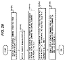
Fig. 26 is a flow chart showing powering-control
executed by a means for converting a train-control command
in the embodiment 4 to control-commands for respective
individual rolling-stock sets.
Fig. 27 is an example of a Table describing information
on the relationship between a train-control command and
corresponding control-commands for respective individual
rolling-stock sets, which is used in the processing shown
in Fig. 26.
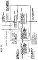
Fig. 28 is a flow chart showing a process of generating
the information described in the Table which is used in the
processing shown in Fig. 26.
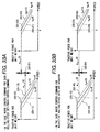
Fig. 29A and Fig. 29B are illustrations showing
examples of the relationship between a train control command
and control commands for respective individual rolling-stock
sets, which are obtained by the processing executed by the
means for converting a train control-command to control
commands for respective individual rolling-stock sets, in
the embodiment 4.
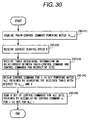
Fig. 30 is a flow chart showing powering-control
executed by a means for converting a train-control command
in an embodiment 5 to control-commands for respective
individual rolling-stock sets.
Fig. 31 is an example of a Table describing information
on the relationship between a train-control command and
corresponding control-commands for respective individual
rolling-stock sets, which is used in the processing shown
in Fig. 30.
Fig. 32 is a flow chart showing a process of generating
the information described in the Table which is used in the
processing shown in Fig. 30.
Fig. 33A and Fig. 33B are illustrations showing
examples of the relationship between a train-control command
and control commands for respective individual rolling-stock
sets, which are obtained by the processing executed by the
means for converting a train-control command in the
embodiment 5.
Fig. 34 is a diagram showing the functional composition
of a means for generating information on a performance of
the whole train in an embodiment 6 according to the present
invention.
Fig. 35 is a diagram showing the functional composition
of a means for generating information on a performance of
the whole train in an embodiment 7 according to the present
invention.
Fig. 36 is a diagram showing the functional composition
of a means for generating information on a performance of
the whole train in an embodiment 8 according to the present
invention.
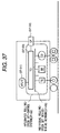
Fig. 37 is a diagram showing an example of a schematic
composition of a train-control system in an embodiment 9
according to the present invention.
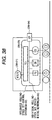
Fig. 38 is a diagram showing another example of a
schematic composition of a train-control system in an
embodiment 9 according to the present invention.
Fig. 39 is a diagram showing another example of a
schematic composition of a train-control system in an
embodiment 9 according to the present invention.
Fig. 40 is a diagram showing another example of a
schematic composition of a train-control system in an
embodiment 9 according to the present invention.
Fig. 41 is a diagram showing an example of a schematic
composition of a train-control system in an embodiment 10
according to the present invention.
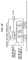
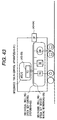
Fig. 42 is a diagram showing an example of a schematic
composition of a train-control system in an embodiment 11
according to the present invention.
Fig. 43 is a diagram showing another example of a
schematic composition of a train-control system in the
embodiment 11 according to the present invention.
Fig. 44 is a diagram showing an example of a schematic
composition of a train-control system in an embodiment 12
according to the present invention.
Fig. 45 is a diagram showing another example of a
schematic composition of a train-control system in the
embodiment 12 according to the present invention.
DETAILED DESCRIPTION OF THE EMBODIMENTS
Embodiment 1:
Hereafter, details of the embodiments according to the
present invention will be explained with reference to the
drawings.
Fig. 1 shows a schematic composition of a train-control
system of an embodiment 1 according to the present invention.
A train in this embodiment includes a single or a
plurality of rolling-stock sets. Further, each rolling-stock
set includes a single or a plurality of vehicles.
First, a train (1-100) consists of a single
rolling-stock set (1-01).
A train-control system (1-101) for the train (1-100)
is provided in each rolling-stock set, and this control system
includes a train-control apparatus (1-02) for creating a
control-command which controls the running of the whole train
(1-100); an individual rolling-stock set-control system
(1-03), which is provided in each individual rolling-stock
set, for performing the running-control of each individual
rolling-stock set; and an integrated individual rolling-stock
set-control system (1-102), which is provided between
the train-control apparatus (1-02) and the individual
rolling-stock set-control system (1-03), for mediating
communication between the train-control apparatus (1-02) and
the individual rolling-stock set-control system (1-03).
The train-control apparatus (1-02) is connected to the
integrated individual rolling-stock set-control system
(1-102), and this control apparatus performs the
sending/receiving of information on the running-control of
the whole train (1-100), together with the integrated
individual rolling-stock set-control system (1-102). The
connection of the train-control apparatus (1-02) and the
integrated individual rolling-stock set-control system
(1-102) is carried out by an integrated rolling-stock
set-connection device (1-04) included in the integrated
individual rolling-stock set-control system (1-102).
The integrated individual rolling-stock set-control
system (1-102) includes the integrated rolling-stock
set-connection device (1-04) and a rolling-stock set-coupling
device (1-05). The integrated rolling-stock
set-connection device (1-04) is connected to the
rolling-stock set-coupling device (1-05), and these devices
exchange information with each other.
The integrated rolling-stock set-connection device
(1-04) is connected to an individual rolling-stock set
device-wiring network (1-09) in the individual rolling-stock
set-control system (1-03), the train-control apparatus
(1-02), and the rolling-stock set-coupling device (1-05).
Also, the integrated rolling-stock set-connection
device (1-04) performs the sending/receiving of information
on running-control of the whole train (1-100) with the
train-control apparatus (1-02). As per the information on
running-control of the whole train (1-100); a control-command
for the train (1-100), to control the running of the
train (1-100), is sent from the train-control apparatus
(1-02), and information on a running-performance of the whole
train (1-100) is sent to the train-control apparatus (1-02).
Further, the integrated rolling-stock set-connection
device (1-04) performs the sending/receiving of information
on running-control of the individual rolling-stock set
(1-01) with each device in the individual rolling-stock
set-control system (1-03). As per the information on
running-control of the individual rolling-stock set (1-01);
information on a running-performance of the individual
rolling-stock set (1-01) is received from the individual
rolling-stock set-control system (1-03), and a control-command
for the individual rolling-stock set (1-01), to
control the running of the individual rolling-stock set
(1-01), is sent to the individual rolling-stock set-control
system (1-03).
Furthermore, if a train includes a plurality of
rolling-stock sets, the integrated rolling-stock set-connection
device (1-04) performs the sending/receiving of
information on running-control of each individual
rolling-stock set with other integrated rolling-stock
set-connection devices via the rolling-stock set-coupling
device (1-05).
Moreover, the integrated rolling-stock set-connection
device (1-04) mediates communication between the train-control
apparatus (1-02) and the individual rolling-stock
set-control system (1-03), and executes an information-converting
operation for the information exchanged between
the train-control apparatus (1-02) and the individual
rolling-stock set-control system (1-03), by reflecting the
train composition state of the train (1-100) on the
information-conversion.
The rolling-stock set-coupling device (1-05) is
connected to the integrated rolling-stock set-connection
device (1-04). Further, if a train includes a plurality of
rolling-stock sets, the rolling-stock set-coupling device
(1-05) is mechanically connected to a rolling-stock set-coupling
device in the neighboring rolling-stock set, and
performs communication with the other rolling-stock sets.
The individual rolling-stock set-control system
(1-03) includes an individual rolling-stock set performance
data-registering device (1-06), an individual rolling-stock
set running state-detection device (1-07), an individual
rolling-stock set-drive device (1-08), and the individual
rolling-stock set device-wiring network (1-09). The
respective devices in the individual rolling-stock set
(1-03) are connected to each other, and exchange information
with each other, via the individual rolling-stock set
device-wiring network (1-09).
The individual rolling-stock set device-wiring
network (1-09) is connected to the integrated rolling-stock
set-connection device (1-04) in the integrated individual
rolling-stock set-control system (1-102), the individual
rolling-stock set performance data-registering device
(1-06) in the individual rolling-stock set-control system
(1-03), the individual rolling-stock set running state-detection
device (1-07), and the individual rolling-stock
set-drive device (1-08). Further, this device-wiring network
(1-09) is used for communication among the above devices.
The individual rolling-stock set performance data-registering
device (1-06) registers information (individual
rolling-set performance information) representing a
running-performance of each rolling-stock set (1-01), with
the individual rolling-stock set-control system (1-03). The
individual rolling-set performance information contains the
length, weight, powering performance, braking performance,
and the environmental resistance (the running resistance,
grade resistance, and curve resistance acting on each
rolling-stock set), of each rolling-stock set (1-01).
Further, the individual rolling-stock set performance
data-registering device (1-06) outputs the individual
rolling-set performance information via the individual
rolling-stock set device-wiring network (1-09).
The individual rolling-stock set running state-detection
device (1-07) detects the running speed of the
rolling-stock set (1-01) in which this individual
rolling-stock set-control system (1-03) is mounted. Further,
the individual rolling-stock set running state-detection
device (1-07) sends the detected running-speed data
(individual rolling-stock set running information) via the
individual rolling-stock set device-wiring network (1-09).
The individual rolling-stock set-drive device (1-08)
controls the running of the individual rolling-stock set
(1-01) by accelerating or decelerating the individual
rolling-stock set (1-01) with tractive or braking force,
respectively. Further, the individual rolling-stock set-drive
device (1-08) receives information which represents
a control command (an individual rolling-stock set-control
command) for each individual rolling-stock set (1-01) via
the individual rolling-stock set device-wiring network
(1-09), and outputs the tractive or braking force
corresponding to the individual rolling-stock set-control
command.
Next, a train (1-300) is composed of two coupled
rolling-stock sets A (1-01A) and B (1-01B).
A train-control system (1-301) for the train (1-300)
includes train-control apparatuses A (1-02) and B (1-02B)
for determining a control-command for the train (1-300), to
control the running of the whole train (1-300); individual
rolling-stock set-control systems A (1-03A) and B (1-03B);
and an integrated rolling-stock set-control system (1-302)
for mediating, provided between the train-control
apparatuses A (1-02A) and B (1-02B), and the individual
rolling-stock set-control systems A (1-03A) and B (1-03B),
for mediating communication between the train-control
apparatuses A (1-02A) and B (1-02B), and the individual
rolling-stock set-control systems A (1-03A) and B (1-03B).
Here, the train-control apparatus A (1-02A) is
connected to an integrated rolling-stock set-connection
device A (1-04A) provided in an integrated rolling-stock
set-control system (1-302), and performs the
sending/receiving of information on running-control of the
whole train (1-300) with the integrated rolling-stock
set-connection device A (1-04A). Also, the train-control
apparatus B (1-02B) is connected to an integrated
rolling-stock set-connection device B (1-04B) provided in
an integrated rolling-stock set-control system (1-302), and
performs the sending/receiving of information on the
running-control of the whole train (1-300), together with
the integrated rolling-stock set-connection device B (1-04B).
Further, the individual rolling-stock set-control
system A (1-03A) includes an individual rolling-stock set
performance data-registering device A(1-06A), an individual
rolling-stock set running state-detection device A (1-07A),
an individual rolling-stock set-drive device A (1-08A), and
an individual rolling-stock set device-wiring network A
(1-09A). The respective devices in the individual
rolling-stock set-control system A (1-03A) are connected to
each other via the individual rolling-stock set device-wiring
network A (1-09A), and exchange information with each
other via the individual rolling-stock set device-wiring
network A (1-09A).
Also, the individual rolling-stock set-control system
B (1-03B) includes an individual rolling-stock set
performance data-registering device B (1-06B), an individual
rolling-stock set running state-detection device B (1-07B),
an individual rolling-stock set-drive device B (1-08B), and
an individual rolling-stock set device-wiring network B
(1-09B). The respective devices in the individual
rolling-stock set-control system B (1-03B) are connected to
each other via the individual rolling-stock set device-wiring
network B (1-09B), and exchange information with each
other via the individual rolling-stock set device-wiring
network B (1-09B). Meanwhile, the functions of the respective
devices in each individual rolling-stock set-control system
are the same as those of respective devices in the individual
rolling-stock set-control system in the train (1-100)
(consisting of a single rolling-stock set).
The integrated rolling-stock set-control system
(1-302) includes the integrated rolling-stock set-connection
device A (1-04A) in the rolling-stock sets A
(1-01A), a rolling-stock set-coupling device A (1-05A), the
integrated rolling-stock set-connection device B (1-04B) in
the rolling-stock sets B (1-01B), and a rolling-stock
set-coupling device B (1-05B). Further, by mechanically
connecting both the rolling-stock set-coupling devices A
(1-05A) and B (1-05B), the individual rolling-stock sets A
(1-01A) and B (1-01B) are coupled, and communication between
the individual rolling-stock sets is carried out via the
devices A (1-05A) and B (1-05B). Thus, the integrated
rolling-stock set-connection device A (1-04A) exchanges
information with the integrated rolling-stock set-connection
device B (1-04B) via the rolling-stock set-coupling
devices A (1-05A) and B (1-05B).
Each integrated rolling-stock set-connection device
is explained below. The integrated rolling-stock set-connection
device A (1-04A) performs the sending/receiving
of information on the running-control of the whole train
(1-300), and of each individual rolling-stock set, with the
train-control apparatus A (1-02A), and with each device in
the individual rolling-stock set-control system A (1-03A)
via the individual rolling-stock set device-wiring network
A (1-09A), respectively. Further, the integrated
rolling-stock set-connection device A (1-04A) also performs
the sending/receiving of information on the running-control
of each of the individual rolling-stock sets A (1-01A) and
B (1-01B) with the integrated rolling-stock set-connection
device B (1-04B) in the individual rolling-stock set B (1-01B)
via the rolling-stock set-coupling device B (1-05B).
Furthermore, the integrated rolling-stock set-connection
device A (1-04A) mediates the communication between the
train-control apparatus A (1-02A) and the integrated
rolling-stock set-control system A (1-03A), and performs a
predetermined conversion process of the information
communicated between the train-control apparatus A (1-02A)
and the integrated rolling-stock set-control system A
(1-03A), corresponding to the train composition state of the
train (1-300).
In the same manner as operations of the integrated
rolling-stock set-connection device A (1-04A), the
integrated rolling-stock set-connection device B (1-04B)
performs the sending/receiving of information on the
running-control of the whole train (1-300), and of each
individual rolling-stock set, with the train-control
apparatus B (1-02B), and with each device in the individual
rolling-stock set-control system B (1-03B) via the
individual rolling-stock set device-wiring network B (1-09B),
respectively. Further, the integrated rolling-stock
set-connection device B (1-04B) also performs the
sending/receiving of information on the running-control of
each of the individual rolling-stock sets A (1-01A) and B
(1-01B) with the integrated rolling-stock set-connection
device A (1-04A) in the individual rolling-stock set A (1-01A)
via the rolling-stock set-coupling device B (1-05B).
Furthermore, the integrated rolling-stock set-connection
device B (1-04B) mediates the communication between the
train-control apparatus B (1-02B) and the integrated
rolling-stock set-control system A (1-03B), and performs a
predetermined conversion process of the information
communicated between the train-control apparatus B (1-02B)
and the integrated rolling-stock set-control system B
(1-03B), corresponding to the train composition state of the
train (1-300).
Fig. 2 shows an information flow in an integrated
rolling-stock set-control system in this embodiment in the
case when the rolling-stock sets are operated in the dividing
operation mode.
The rolling-stock set A (2-01A) and the rolling-stock
set B (2-01B) are independently operated as respective train
1 (2-100) and train 2 (2-200) in the dividing operation mode.
In this operation, an integrated rolling-stock set-control
system 1 (2-101) and an integrated rolling-stock set-control
system 2 (2-201) in the respective trains 1 and 2 function
separately. That is, an integrated rolling-stock set-connection
device A (2-04A) and an integrated rolling-stock
set-connection device B (2-04B) in the respective trains 1
and 2 do not perform communication with each other, and
perform their information-processing separately in the
respective trains 1 and 2. Therefore, in the following, only
the respective train 1 (2-100) or the rolling-stock set A
(2-01A) will be explained.
First, the integrated rolling-stock set-control
system 1 (2-101) performs the sending/receiving of
information (2-21A) on the running-control of the whole train
1 (2-100) with the train-control apparatus A (2-02A) by using
the integrated rolling-stock set-control device A (2-04A).
As per the information (2-21A) on the running-control of the
whole train 1 (2-100); a control-command 1 for the train 1
(2-100), to control the running of the train 1 (2-100), is
sent from the train-control apparatus A (2-02A), and the whole
train running-performance information 1, which represents
a running-performance of the whole train 1 (2-100), is sent
to the train-control apparatus A (2-02A).
Further, the integrated rolling-stock set-control
system 1 (2-101) performs the sending/receiving of
information (2-22A) on the running-control of the individual
rolling-stock set A (2-01A) with the individual rolling-stock
set-control system A (2-03A) by using the integrated
rolling-stock set-control device A (2-04A). As per the
information (2-22A) on the running-control of the individual
rolling-stock set A (2-01A); individual rolling-stock set
performance information A, which represents a performance
of the individual rolling-stock set A (2-01A), and individual
rolling-stock set running-state information A, which
represents the running speed of the individual rolling-stock
set A (2-01A), are sent from an individual rolling-stock set
performance information-registering device in the
individual rolling-stock set A (2-01A) and an individual
rolling-stock set running state-detection device A (2-07).
Moreover, an individual rolling-stock set-control command
A for the individual rolling-stock set A (2-01A) is output
to an individual rolling-stock set-drive device A (2-08A).
Here, since the train 1 (2-100) includes only one
individual rolling-stock set, the integrated rolling-stock
set-connection device A (2-04A) in the integrated
rolling-stock set-control system 1 (2-101) does not perform
the sending/receiving of information with other individual
rolling-stock sets via the rolling-stock set-coupling device
A (2-05A).
In Fig. 2, the integrated individual rolling-stock
set-connection device A (2-04A) in the integrated
rolling-stock set-control system 1 (2-101) mediates the
communication between the train-control apparatus A (2-02A)
and the individual rolling-stock set-control system A
(2-03A), and performs a predetermined information-converting
process, corresponding to the train composition
state of the train 1 (2-100). In this information-converting
process, the information (2-21A) (a train-control command
1) on the running-control of the whole train 1 (2-100), which
is output from the train-control apparatus A (2-02A), is
converted to the information (2-22A) (an individual
rolling-stock set-control command A) on the running-control
of the individual rolling-stock set A (2-01A), and is further
input to the individual rolling-stock set-control system A
(2-03A). As per the information flow reverse to the above
flow; the information (2-22A) (the individual rolling-stock
set-control command A) on the running-control of the
individual rolling-stock set A (2-01A) output from the
individual rolling-stock set-control system A (2-03A) is
converted to the information (2-21A) (a train-control
command 1) on the running-control of the whole train 1 (2-100),
and is input to the train-control apparatus A (2-02A).
Fig. 3 shows an information flow in an integrated
rolling-stock set-control system in this embodiment in the
case where the rolling-stock sets are operated in the coupling
operation mode.
Meanwhile, in the case where a train consists of a
plurality of rolling-stock sets as well as this embodiment,
the role of outputting a control-command for the whole train
is allocated to only one of the train-control apparatuses
provided in the respective rolling-stock sets of the train.
Here, the rolling-stock set to which the role of controlling
the whole train is allocated is defined as a master
rolling-stock set, and the other sets are defined as slave
sets. Therefore, there is only one master rolling-stock set
in one train. Frequently, the head rolling-stock set of a
train is determined as the master set. However, in the
train-control system, the method of determining the master
rolling-stock set is not restricted to the above master
set-determination method.
A rolling-stock set A (3-01A) and a rolling-stock set
B (3-01B) are operated in a lot as one train 3 (3-300) in
the coupling operation mode. In this operation, one
integrated rolling-stock set-control system 3 (3-301) is
composed so as to control the rolling-stock set A (3-01A)
and a rolling-stock set B (3-01B) in a lump, and necessary
information is communicated between an integrated
rolling-stock set-connection device A (3-04A) and an
integrated rolling-stock set-connection device B (3-04B).
In the train 3 (3-300) in this embodiment, the role
of sending the control-command for the whole train 3 (3-300)
is allocated to a train-control apparatus A (3-02A)
provided in the rolling-stock set A (3-01A). Accordingly,
the rolling-stock set A (3-01A) including the train-control
apparatus A (3-02A) is the master set, and the rolling-stock
set B (3-01B) other than the set A (3-01A) is a slave set.
First, the control performed in the rolling-stock set
A (3-01A) is explained below. The integrated rolling-stock
set-control system (3-301) performs the sending/receiving
of information (3-21A) on the running-control of the whole
train 3 (3-300) with the train-control apparatus A (3-02A)
by using the individual rolling-stock set-connection device
A (3-04A). The contents of the information (3-21A) on the
running-control of the whole train 3 (3-300) are similar to
those of the information on the running-control of the
above-described train 1 (2-100).
Further, the integrated rolling-stock set-control
system (3-301) performs the sending/receiving of information
(3-22A) on the running-control of the individual
rolling-stock set A (3-01A) with an individual rolling-stock
set-control system A (3-03A) by using the individual
rolling-stock set-connection device A (3-04A). Also, The
contents of the information (3-22A) on the running-control
of the individual rolling-stock set A (3-01A) are similar
to those of the information on the running-control of the
above-described train 1 (2-100).
Here, in the integrated rolling-stock set-control
system (3-301), the individual rolling-stock set-connection
device A (3-04A) performs the sending/receiving of
information (3-22B) on the running-control of the individual
rolling-stock set B (3-01B) with an individual rolling-stock
set-connection device B (3-04B) in the individual
rolling-stock set B (3-01B) via a rolling-stock set-coupling
device A (3-05B). As per the information (3-22B) on the
running-control of the individual rolling-stock set B
(3-01B); individual rolling-stock set performance
information B representing the running-performance of the
rolling-stock set B (3-01B), which is one of attributions
of the rolling-stock set B (3-01B), is input to the individual
rolling-stock set-connection device A (3-04A), and
individual rolling-stock set-control command B representing
a running-control command for the rolling-stock set B (3-01B)
is output from the individual rolling-stock set-connection
device A (3-04A).
Further, the individual rolling-stock set-connection
device A (3-04A) outputs the information (3-22A) on the
running-control of the individual rolling-stock set A
(3-01A) to the individual rolling-stock set-connection
device B (3-04B) in the individual rolling-stock set B (3-01B)
via the rolling-stock set-coupling device A (3-05A). The
information (3-22A) on the running-control of the individual
rolling-stock set A (3-01A) includes individual rolling-stock
set performance information A representing the
running-performance of the rolling-stock set A (3-01A),
which is one of attributions of the rolling-stock set A
(3-01A).
Next, the control performed in the rolling-stock set
B (3-01B) is explained below. The integrated rolling-stock
set-control system (3-301) performs the sending/receiving
of information (3-21B) on the running-control of the whole
train 3 (3-300) with the train-control apparatus B (3-02B)
by using the individual rolling-stock set-connection device
B (3-04B). The contents of the information (3-21B) on the
running-control of the whole train 3 (3-300) is similar to
those of the information on the running-control of the
above-described train 1 (2-100).
Further, the integrated rolling-stock set-control
system (3-301) performs the sending/receiving of information
(3-22B) on the running-control of the individual
rolling-stock set B (3-01B) with an individual rolling-stock
set-control system B (3-03B) by using the individual
rolling-stock set-connection device B (3-04B). Also, The
contents of the information (3-22B) on the running-control
of the individual rolling-stock set B (3-01B) is similar to
those of the information on the running-control of the
above-described train 1 (2-100).
Here, in the integrated rolling-stock set-control
system (3-301), the individual rolling-stock set-connection
device B (3-04B) receives the information (3-22A) on the
running-control of the individual rolling-stock set A
(3-01A) from an individual rolling-stock set-connection
device A (3-04A) in the individual rolling-stock set A (3-01A)
via a rolling-stock set-coupling device B (3-05B). The
information (3-22A) on the running-control of the individual
rolling-stock set A (3-01A) includes individual rolling-stock
set performance information A representing the
running-performance of the rolling-stock set A (3-01A),
which is one of attributions of the rolling-stock set A
(3-01A). Further, the individual rolling-stock set-connection
device B (3-04B) performs the sending/receiving
of information (3-22B) on the running-control of the
individual rolling-stock set B (3-01B) with an individual
rolling-stock set-connection device A (3-04A) in the
individual rolling-stock set A (3-01A) via a rolling-stock
set-coupling device A (3-05B). As per the information (3-22B)
on the running-control of the individual rolling-stock set
B (3-01B); individual rolling-stock set-control command B
representing a running-control command for the rolling-stock
set B (3-01B) is input to the individual rolling-stock
set-connection device B (3-04B), and individual rolling-stock
set performance information B representing the
running-performance of the rolling-stock set B (3-01B),
which is one of attributions of the rolling-stock set B
(3-01B), and is output from the individual rolling-stock
set-connection device B (3-04B).
In Fig. 3, the integrated individual rolling-stock
set-connection device A (3-04A) in the integrated
rolling-stock set-control system 3 (3-301) mediates the
communication between the train-control apparatus A (3-02A)
and the individual rolling-stock set-control system A
(3-03A), and between the train-control apparatus A (3-02A)
and the individual rolling-stock set-control system A
(3-03B), and performs a predetermined information-converting
process, corresponding to the composition state
of the train 3 (3-300). In this information-converting
process, the information (3-21A) (a train-control command
3) on the running-control of the whole train 1 (3-300), which
is output from the train-control apparatus A (3-02A), is
converted to the information (3-22A) (an individual
rolling-stock set-control command A) on the running-control
of the individual rolling-stock set A (3-01A) and the
information (3-22B) (an individual rolling-stock set-control
command B) on the running-control of the individual
rolling-stock set B (3-01B), and is further input to the
individual rolling-stock set-control system A (2-03A) and
the individual rolling-stock set-control system B (2-03B).
As the information flow reverse to the above flow, the
information (3-22A) (the individual rolling-stock set-control
command A) on the running-control of the individual
rolling-stock set A (3-01A) output from the individual
rolling-stock set-control system A (3-03A) and the
information (3-22B) (the individual rolling-stock set-control
command B) on the running-control of the individual
rolling-stock set B (3-01B) output from the individual
rolling-stock set-control system A (3-03A) are converted to
the information (3-21A) (a train-control command 3) on the
running-control of the whole train 3 (3-300), and is input
to the train-control apparatus A (3-02A).
Also, the integrated individual rolling-stock set-connection
device B (3-04B) in the integrated rolling-stock
set-control system 3 (3-301) mediates the communication
between the train-control apparatus B (3-02B) and the
individual rolling-stock set-control system A (3-03A), and
between the train-control apparatus B (3-02B) and the
individual rolling-stock set-control system B (3-03B), and
performs a predetermined information-converting process,
corresponding to the composition state of the train 3 (3-300).
In this information-converting process, since the individual
rolling-stock set B (3-01B) is a slave set, the outputting
the information (3-22B) (a train-control command 3) on the
running-control of the whole train 1 (3-300), which is output
from the train-control apparatus B (3-02B), is stopped by
the integrated individual rolling-stock set-connection
device B (3-04B). Thus, the train-control apparatus B (3-02B)
does not actually act on any individual rolling-stock set
in the train 3 (3-300). However, the information (3-22A) (the
individual rolling-stock set-control command A) on the
running-control of the individual rolling-stock set A
(3-01A) output from the individual rolling-stock set-control
system A (3-03A) and the information (3-22B) (the individual
rolling-stock set-control command B) on the running-control
of the individual rolling-stock set B (3-01B) output from
the individual rolling-stock set-control system A (3-03A)
are converted to the information (3-21B) (a train-control
command 3) on the running-control of the whole train 3 (3-300),
and is input to the train-control apparatus B (3-02B).
The above-described train-control system with the
integrated rolling-stock set-control systems of this
embodiment possesses the following features.
The kinds of information which the integrated
rolling-stock set-control system exchanges with the
apparatus or devices are fixed, independent of whether each
train including only one rolling-stock set is operated, in
the dividing operation mode, or a train with different types
of rolling-stock sets is operated, in the coupling operation
mode. This is because measures handling effects of a train
composition state on a train-control, are centered at only
the integrated rolling-stock set-control system.
Further, the contents of the information which the
integrated rolling-stock set-control system exchanges with
the apparatus or devices, are ones common to usual
rolling-stock sets, so as to exclude information particular
to each of the dividing and coupling operation modes. This
also means that the effects of a train composition state on
a train-control, are handled only by the conversion of
information, which is performed by the integrated
rolling-stock set-control system.
As described above, in this embodiment, the train-control
system for controlling the running of a train
includes; the train-control apparatus for creating a
control-command to control the whole train in a lot; each
individual rolling-stock set-control system which is
provided in each individual rolling-stock set, for
controlling the running of each set; and the integrated
rolling-stock set-control system which stands between the
train-control system and the individual rolling-stock
set-control systems, for mediating the communication between
the train-control system and each individual rolling-stock
set-control system.
Further, in this embodiment, the integrated
rolling-stock set-control system includes each rolling-stock
set-coupling device for mechanically coupling two
neighboring rolling-stock sets, and performing the
sending/receiving of information between the two neighboring
rolling-stock sets, and each integrated rolling-stock
set-connection device for exchanging the information on the
running-control of each set with each individual
rolling-stock set directly or via the rolling-stock set-coupling
devices.
Furthermore, in this embodiment, each integrated
rolling-stock set-connection device performs the converting
of the information between the information received from and
sent to the train-control apparatus, and the information
received from and sent to each individual rolling-stock set.
In this information-converting operation, the information
received from and sent to the train-control apparatus and
the information received from and sent to each individual
rolling-stock set are converted to each other taking the train
composition state into account. That is, when the information
received from the train-control apparatus is converted to
be sent to each individual rolling-stock set, the received
information on the whole train, obtained by viewing all the
sets of the train in a lump, is converted to be adapted to
each rolling-stock set while the train composition state is
considered. Also, when the information received from the
individual rolling-stock sets is converted and sent to the
train-control apparatus, the information received from the
individual rolling-stock sets is integrated into the
information on the whole train, obtained by viewing all the
sets of the train in a lump while the train composition state
is considered.
As described above, the train-control system of this
embodiment has the following effects on the running-control
of a train.
In this embodiment, the train-control system is divided
into the train-control apparatus, the individual
rolling-stock set-control systems, and the integrated
rolling-stock set-control system. According to this division
of the train-control system, it is possible to unify the
integrated information on the whole train, which the
train-control apparatus processes, even if the composition
of a train is from that consisting of a single rolling-stock
set to that consisting of different rolling-stock sets.
Therefore, since the train-control apparatus need not
directly correspond to the change in the train composition
state, it is not necessary for the train-control apparatus
to implement processes particular to each train composition
state. That is, the train-control apparatus has only to
perform running-control for trains in general. This
considerably reduces the processing load of the train-control
apparatus which must handle controls corresponding
to the respective dividing and coupling operation modes.
Moreover, it is possible to use a general device for the
train-control apparatus independent of the dividing or
coupling operation mode, which in turn makes it easier to
realize the switching operation mode between the dividing
and coupling operation modes.
Further, according to the above train-control system,
the information which each individual rolling-stock set-control
system directly processes can always be restricted
to that related only to each rolling-stock set, even if the
train composition state changes. Therefore, each individual
rolling-stock set-control system need not directly
correspond with the change in the train composition state,
and this in turn makes it unnecessary to implement processing
particular to each train composition state. That is, each
individual rolling-stock set-control system has only to
perform the running-control common to the individual
rolling-stock sets. This considerably reduces the processing
load of each individual rolling-stock set-control system
which must handle controls corresponding to the respective
dividing and coupling operation modes. Moreover, it is
possible to use a general device for each individual
rolling-stock set control system, independent of the
dividing or coupling operation mode, which in turn makes it
easier to realize the switching operation mode between the
dividing and coupling operation modes.
Furthermore, by composing the above-described
train-control system, an information-converting operation
between that sent from the train-control apparatus to each
individual rolling-stock set-control system and that sent
from the respective individual rolling-stock set-control
systems to the train-control apparatus, can be carried out,
while this converting operation is adapted to the train
composition state. Also, each integrated rolling-stock
set-control system converts information sent from the
respective individual rolling-stock set-control systems to
the information on the whole train, obtained by viewing all
the sets of the train in a lump. For this information-converting
operation, the optimal contents of the
information obtained by viewing all the sets of the train
in a lump, are defined in advance by taking the attributions
(the running-performances) of the respective individual
rolling-stock sets into account. By the above definition of
the information on the whole train, it is possible to generate
information adequate to cope with all the sets in the whole
train in a lump, and send the generated information to the
train-control apparatus. Also, each integrated rolling-stock
set-control system converts the information on the
whole train, sent from the train-control apparatus, and
obtained by viewing all the sets of the train in a lump, to
information for the respective individual rolling-stock
set-control systems. For this information-converting
operation, the optimal contents of the information for the
respective individual rolling-stock set-control systems are
defined in advance by taking the attributions (the
running-performances) of the respective individual
rolling-stock sets into account. By the above definition of
the information on the whole train, it is possible to generate
information adequate for the respective individual
rolling-stock sets, and send the generated information to
each of the individual rolling-stock sets. Thus, it becomes
possible to optimize the running-control of a train, pursuant
to the train composition state, by taking the performance
of the whole train and that of each rolling-stock set in the
train into account.
Embodiment 2:
In the above embodiment 1, in the train-control system
for controlling the running of a train; the train-control
apparatus for determining a control-command to control the
whole train in a lot; each individual rolling-stock set-control
system, which is provided in each individual
rolling-stock set, for controlling the running of each set;
and; the integrated rolling-stock set-control system which
stands between the train-control system and the individual
rolling-stock set-control systems, for mediating the
communication between the train-control system and each
individual rolling-stock set-control system; are provided.
According to the above composition of the train-control
system, even if the train composition state change pursuant
to the dividing or coupling operation mode, since only the
integrated rolling-stock set-control system copes with
effects of the change on the running-control of the train,
the train-control apparatus and each individual rolling-stock
set need not consider the change in the train
composition state. Further, it has been described above that
it becomes possible to optimize the running-control of a train,
corresponding to the train composition state, by taking the
performance of the whole train and that of each rolling-stock
set in the train into account, because the integrated
rolling-stock set-control system adequately operates the
communication between the train-control apparatus and the
respective individual rolling-stock set-control systems.
In this embodiment, the operations for the
communication between the train-control apparatus and the
respective individual rolling-stock set-control systems,
performed by the integrated rolling-stock set-control system,
are concretely set. Further, an communication means which
takes the change in the running-performance of the whole train,
corresponding with the change in the train composition state,
into account, is incorporated into the integrated
rolling-stock set-control system. That is, the integrated
rolling-stock set-control system receives individual
rolling-stock set performance information representing
running-performances of the respective individual
rolling-stock sets from the respective individual
rolling-stock set-control systems, and outputs whole-train
running-performance data representing a running-performance
of the whole train, corresponding with the train composition
state, to the train-control apparatus.
The integrated rolling-stock set-control system in
this embodiment includes the integrated rolling-stock
set-connection device and the rolling-stock set-coupling
device. The rolling-stock set-coupling device mechanically
couples two neighboring rolling-stock sets, and performs
exchange between the two neighboring rolling-stock sets. The
integrated rolling-stock set-connection device performs;
the sending/receiving of information on the running-control
of the whole train, with the train-control apparatus to which
this integrated rolling-stock set-control system is
connected, and; the sending/receiving of information on the
running-control of each individual rolling-stock set with
each individual rolling-stock set-control system directly
or via the rolling-stock set-coupling device.
Also, The integrated rolling-stock set-connection
device manages the information representing the running-performance
of the whole train, (the whole-train
running-performance), and outputs the whole-train
running-performance data to the train-control apparatus to
which this integrated rolling-stock set-control system is
connected.
Fig. 4 shows the functional composition of the
integrated rolling-stock set-connection device in this
embodiment.
The integrated rolling-stock set-connection device
(4-01) shown in Fig. 4 includes the following processing
means.
First, a means (4-11) for inputting/outputting
information on individual rolling-stock sets is provided.
This means performs the sending/receiving of individual
rolling-stock set performance information, which represents
a running-performance of each individual rolling-stock set,
(the running-performance information (4-21A) on own set, and
running-performance information (4-21B) on the other set),
with an individual rolling-stock set performance data
registering device (4-03) in an individual rolling-stock
set-control system (4-02) and a rolling-stock set-coupling
device (4-04), respectively. Further, information (4-22) on
performances of all individual rolling-stock sets is
generated by accumulating the individual rolling-stock set
performance information for all the individual rolling-stock
sets in the train, and is output to a means (4-12) for
registering information on performances of all individual
rolling-stock sets.
Next, the means (4-12) for registering information on
performances of all individual rolling-stock sets is
included. This means receives the information (4-22) on
performances of all individual rolling-stock sets from the
means (4-11) for inputting/outputting information on
individual rolling-stock sets, and registers the information
(4-22) on performances of all individual rolling-stock sets,
which is used for information-processing executed by the
integrated rolling-stock set-connection device (4-01).
Further, the means (4-12) sends the information (4-22) to
a means (4-13) for generating information on performance of
the whole train.
The integrated rolling-stock set-connection device
(4-01) also includes the means (4-13) for generating
information on the performance of the whole train. This means
receives the information (4-22) on performances of all
individual rolling-stock sets from the means (4-11) for
inputting/outputting information on individual rolling-stock
sets, and generates information (4-23) on the
performance of the whole train, and sends the information
(4-23) on the performance of the train as a whole to a means
(4-14) for registering information on a performance of the
whole train.
Further, the integrated rolling-stock set-connection
device (4-01) includes the means (4-14) for registering
information on the performance of the whole train. This means
receives the information (4-23) on the performance of the
whole train from the means (4-13) for generating information
on the performance of the whole train, and registers the
information (4-23) on a performance of the whole train, which
is used for information-process executed by the train-control
apparatus (4-05). Also, this means sends the
information (4-23) on the performance of the whole train to
the train-control apparatus (4-05).
Fig. 5 shows a flow chart of processing executed by
the integrated rolling-stock set-connection device (4-01)
in this embodiment.
In step (5-01), the information on the running-performance
of each individual rolling-stock set is received
from each individual rolling-stock set in the train. The
process in step (5-01) is executed by the means (4-11) for
inputting/outputting information on individual rolling-stock
sets.
In step (5-02), it is determined whether or not there
is any rolling-stock set (other set) other than the set (its
own set), in which this integrated rolling-stock set-connection
device is mounted, in the train. This integrated
rolling-stock set-connection device performs the
determination in step (5-02), by detecting the presence of
an integrated rolling-stock set-connection device in another
set, with communication via the rolling-stock set-coupling
devices. If it is determined that there is another
rolling-stock set, the process goes to step (5-03), otherwise
it goes to step (5-04). The process in step (5-02) is executed
by the means for inputting/outputting information on
individual rolling-stock sets.
In step (5-03), the information on the running-performance
of its own set is sent to an integrated
rolling-stock set-connection device of the other set. Also,
the process in step (5-03) is executed by the means for
inputting/outputting information on individual rolling-stock
sets.
In step (5-04), the information on the running-performance
of the whole train is generated based on the
information on the running-performances of the individual
rolling-stock sets, received from the respective individual
rolling-stock sets. The process in step (5-04) is executed
by the means for generating information on the running-performance
of the whole train.
In step (5-05), the generated information on the
running-performance of the whole train is sent to the
train-control apparatus. The process in step (5-05) is
executed by the means for registering information on a
running-performance of the whole train.
The integrated rolling-stock set-connection device
performs the information-converting operation,
corresponding to the train composition state, by executing
the information processing shown in Fig. 4 and Fig. 5.
Fig. 6 shows an information flow in the integrated
rolling-stock set-control system in the case where the
rolling-stock sets are operated as two trains in the dividing
operation mode.
An individual rolling-stock set A (6-00A) and an
individual rolling-stock set B (6-00B) are separately
operated as a train 1 (6-100) and a train 2 (6-200), in the
dividing operation mode. In these train compositions, an
integrated rolling-stock set-control system 1 (6-101) and
an integrated rolling-stock set-control system 2 (6-201) are
independently provided in the two trains, respectively. That
is, the information flow in an integrated rolling-stock
set-connection device A (6-01A) and that in an integrated
rolling-stock set-connection device B (6-01B) are
independent of each other. Therefore, only the train 1 (6-100),
or the individual rolling-stock set A (6-00A) is explained
below.
First, in the integrated rolling-stock set-connection
device A (6-01A) of the integrated rolling-stock set-control
system 1 (6-101), a means (6-11A) for inputting/outputting
information on an individual rolling-stock set receives
information A (6-21A) on the running-performance of the
individual rolling-stock set A (6-00A) from an individual
rolling-stock set performance data-registering device A
(6-03A) in an individual rolling-stock set-control system
A (6-02A). The means (6-11A) for inputting/outputting
information on an individual rolling-stock set generates
information (6-22A) on all individual rolling-stock sets,
based on the received information A (6-21A) on the
running-performance of the individual rolling-stock set A
(6-00A). In this example, since the train 1(6-100) includes
only the individual rolling-stock set A (6-00A), the
information A (6-21A) on the running-performance of the
individual rolling-stock set A (6-00A) is used as the
information (6-22A) on all individual rolling-stock sets.
Next, a means (6-12A) for registering information on
all individual rolling-stock sets registers the information
(6-22A) on all individual rolling-stock sets received from
the means (6-11A) for inputting/outputting information on
an individual rolling-stock set.
Further, a means (6-13A) for generating information
on the performance of the whole train generates information
1 (6-23A) on the running-performance of the whole
train1(6-100), based on the information (6-22A) on all
individual rolling-stock sets, which is received from the
means (6-12A) for registering information on all individual
rolling-stock sets. In this example, since the train 1 (6-100)
includes only the individual rolling-stock set A (6-00A),
the contents of the information (6-22A) on all individual
rolling-stock sets, that is: those of the information A
(6-21A) on the running-performance of the individual
rolling-stock set A (6-00A); are used as the information 1
(6-23A) on the running-performance of the whole train 1
(6-100).
Furthermore, a means (6-14A) for registering
information on a performance of the whole train registers
the information 1 (6-23A) on the running-performance of the
whole train 1 (6-100), and the information 1 (6-23A) on the
running-performance of the whole train 1 (6-100) is sent to
a train-control apparatus A (6-05A) from the integrated
roiling-stock set-connection device A (6-01A) by the means
(6-14A) for registering information on the performance of
the whole train.
Fig. 7 shows an information flow in an integrated
rolling-stock set-control system in the case where the
rolling-stock sets are operated in the coupling operation
mode.
An individual rolling-stock set A (7-00A) and an
individual rolling-stock set B (7-00B) are operated together
as a train 3 (7-300), in the coupling operation mode. In this
train composition, one integrated rolling-stock set-control
system 3 (7-301) is composed so as to execute a supervisory
control of an individual rolling-stock set A (7-00A) and an
individual rolling-stock set B (7-00B), in the train 3 (7-300).
Thus, the information flow in an integrated rolling-stock
set-connection device A (7-01A) and that in an integrated
rolling-stock set-connection device B (7-01B) interact with
each other.
First, the information flow in the individual
rolling-stock set A (7-00A) is explained below. In the
integrated rolling-stock set-connection device A (7-01A) of
the integrated rolling-stock set-control system 3 (7-301),
a means (7-11A) for inputting/outputting information on an
individual rolling-stock set receives information A (7-21A)
on the running-performance of the individual rolling-stock
set A (7-00A) from an individual rolling-stock set
performance data-registering device A (7-03A) in an
individual rolling-stock set-control system A (7-02A).
Further, the means (7-11A) receives information B (7-21B)
on the running-performance of the individual rolling-stock
set B (7-00B) from a rolling-stock set-coupling device A
(7-04A). Furthermore, the information A (7-21A) on the
running-performance of the individual rolling-stock set A
(7-00A) is sent to the integrated rolling-stock set-connection
device B (7-01B) in the individual rolling-stock
set B (7-00B), via the rolling-stock set-coupling device A
(7-04A). Moreover, information (7-22A) on the performance
of all individual rolling-stock sets is generated by
accumulating the information A (7-21A) and B (7-21B) on the
running-performance of the individual rolling-stock sets A
(7-00A) and B (7-00B).
Next, a means (7-12A) for registering information on
all individual rolling-stock sets registers the information
(7-22A) on all individual rolling-stock sets received from
the means (7-11A) for inputting/outputting information on
an individual rolling-stock set.
Further, a means (7-13A) for generating information
on the performance of the whole train generates information
3 (7-23A) on the running-performance of the whole train 3
(7-300), based on the information (7-22A) on all individual
rolling-stock sets, which is received from the means (7-12A)
for registering information on all individual
rolling-stock sets.
Furthermore, a means (7-14A) for registering
information on the performance of the whole train registers
the information 3 (7-23A) on the running-performance of the
whole train 3 (7-300), and the information 3 (7-23A) on the
running-performance of the whole train 3 (7-300), is sent
to a train-control apparatus A (7-05A) from the integrated
rolling-stock set-connection device A (7-01A) by the means
(7-14A) for registering information on the performance of
the whole train.
On the other hand, the information flow in the control
of the individual rolling-stock set B (7-00B) is explained
as follows. In the integrated rolling-stock set-connection
device B (7-01B) of the integrated rolling-stock set-control
system 3 (7-301), a means (7-11B) for inputting/outputting
information on an individual rolling-stock set receives
information B (7-21B) on the running-performance of the
individual rolling-stock set B (7-00B) from an individual
rolling-stock set performance data-registering device B
(7-03B) in an individual rolling-stock set-control system
B (7-02B). Further, the means (7-11B) receives the
information A (7-21A) on the running-performance of the
individual rolling-stock set A (7-00A) from a rolling-stock
set-coupling device B (7-04B). Furthermore, the information
B (7-21B) on the running-performance of the individual
rolling-stock set B (7-00B) is sent to the integrated
rolling-stock set-connection device A (7-01A) in the
individual rolling-stock set A (7-00A), via the rolling-stock
set-coupling device B (7-04B). Moreover, information
(7-22B) on the performance of all individual rolling-stock
sets is generated by accumulating the information A (7-21A)
and B (7-21B) on the running-performance of the individual
rolling-stock sets A (7-00A) and B (7-00B).
Next, a means (7-12B) for registering information on
all individual rolling-stock sets registers the information
(7-22B) on all individual rolling-stock sets received from
the means (7-11B) for inputting/outputting information on
an individual rolling-stock set.
Further, a means (7-13B) for generating information
on the performance of the whole train generates information
3 (7-23B) on the running-performance of the whole train 3
(7-300), based on the information (7-22B) on all individual
rolling-stock sets, which is received from the means (7-12B)
for registering information on all individual
rolling-stock sets.
Furthermore, a means (7-14B) for registering
information on the performance of the whole train registers
the information 3 (7-23B) on the running-performance of the
whole train 3 (7-300), and the information 3 (7-23B) on the
running-performance of the whole train 3 (7-300), is sent
to a train-control apparatus B (7-05A) from the integrated
rolling-stock set-connection device B (7-01B) by the means
(7-14B) for registering information on the performance of
the whole train.
Fig. 8 shows the functional composition of, and the
information flow, in the means for generating information
on the performance of the whole train in this embodiment.
First, in this embodiment, a means (8-01) for
generating information on the performance of the whole train
receives information (8-11) obtained by accumulating
running-performances of all individual rolling-stock sets,
from the means for registering information on the
running-performances of all individual rolling-stock sets.
The information (8-11) on the running-performances of all
individual rolling-stock sets contains the length, weight,
braking performance expressed with the braking force per unit
weight, powering performance expressed with the tractive
force per unit weight, the environmental resistance (the
running resistance, grade resistance, and curve resistance
acting on each rolling-stock set), of each individual
rolling-stock set in the train.
Next, the means (8-01) for generating information on
the performance of the whole train sends information (8-21)
on the running-performance of the whole train to the means
for registering the information on the performance of the
whole train. The information (8-21) on the running-performance
of the whole train contains the length, weight,
braking performance expressed with the braking force per unit
weight, powering performance expressed with the tractive
force per unit weight, the environmental resistance (the
running resistance, grade resistance, and curve resistance
acting on each rolling-stock set), of the train as a whole.
Further, the means (8-01) for generating information
on the performance of the whole train includes a train
length-calculating means (8-02), a train weight-calculating
means (8-03), a train braking performance-calculating means
(8-04), a train powering performance-calculating means
(8-05), and a train environmental resistance-calculating
means (8-06).
Furthermore, the train length-calculating means
(8-02) obtains the train length (8-22) based on the
information (8-11) on the running-performances of all
individual rolling-stock sets.
Moreover, the train weight-calculating means (8-03)
obtains the train weight (8-23) based on the information
(8-11) on the running-performances of all individual
rolling-stock sets.
Also, the train braking performance-calculating means
(8-04) obtains the train braking performance (8-24) based
on the information (8-11) on the running-performances of all
individual rolling-stock sets.
Further, the train powering performance-calculating
means (8-05) obtains the train powering performance (8-25)
based on the information (8-11) on the running-performances
of all individual rolling-stock sets.
In addition, the train environmental resistance-calculating
means (8-06) obtains the train environmental
resistance (8-26) based on the information (8-11) on the
running-performances of all individual rolling-stock sets.
The information (8-21) on the running-performance of
the whole train is output as a data set of the train length
(8-22), the train weight (8-23), the train braking
performance (8-24), the train powering performance (8-25),
and the train environmental resistance (8-26).
Fig. 9 shows a flow chart of processing executed by
the means for generating information on the performance of
the whole train.
In step (9-01), this means receives the information
on the running-performances of all individual rolling-stock
sets containing the train length data, the train weight data,
the train braking performance data, the train powering
performance data, and the train environmental resistance
data, from the means for registering information on all
individual rolling-stock sets.
In step (9-02), the processes (step (9-03) - step
(9-07)), of generating each data in the information on the
performance of the whole train, are executed.
In step (9-03), the train length-calculating means
generates the train length data, based on the length data
of each individual rolling-stock set, contained in the
information on the running-performances of all individual
rolling-stock sets.
In step (9-04), the train weight-calculating means
generates the train weight data, based on the weight data
of each individual rolling-stock set, contained in the
information on the running-performances of all individual
rolling-stock sets.
In step (9-05), the train braking performance-calculating
means generates the train braking performance
data, based on the braking performance data of each individual
rolling-stock set, contained in the information on the
running-performances of all individual rolling-stock sets.
In step (9-06), the train powering performance-calculating
means generates the train powering performance
data, based on the powering performance data of each
individual rolling-stock set, contained in the information
on the running-performances of all individual rolling-stock
sets.
In step (9-07), the train environmental
resistance-calculating means generates the train
environmental resistance data, based on the powering
performance data of each individual rolling-stock set,
contained in the information on the running-performances of
all individual rolling-stock sets.
In step (9-08), on receiving the results of the
processes in steps (9-03) - (9-07), the information on the
performance of the whole train, composed of a set of the train
length data, the train weight data, the train braking
performance data, the train powering performance data, and
the train environmental resistance data, is sent to the means
for registering information on the performance of the whole
train.
In the following, each processing means included in
the means for generating information on the performance of
the whole train will be explained in more detailed.
First, the train length-calculating means is
explained.
The train length-calculating means obtains the train
length Ltrain, based on the length Li of each individual
rolling-stock set i (i = A, B, ... (for all individual
rolling-stock sets)), using the following equation.
Ltrain = Σ(Li )
The symbol Σ in the right hand side of the above
equation means that a value or an equation in the parenthesis
is summed for all possible i. Accordingly, Σ(Li) indicates
the summation with respect to i.
Here, even if a train includes a single individual
rolling-stock set, the train length is set to the length of
the single individual rolling-stock set by executing the
above calculation.
As described above, in this embodiment, since the train
length-calculating means obtains the train length, with
reference to the performance data of all individual
rolling-stock sets in a train, the train length-calculating
means can generate the train length data for a train
consisting of any types and any number of rolling-stock sets,
corresponding to the composition state of the train.
Further, the train weight-calculating means is
explained.
The train weight-calculating means obtains the train
weight Mtrain, based on the length Mi of each individual
rolling-stock set i (i = A, B, ... (for all individual
rolling-stock sets)), using the following equation.
Mtrain = Σ(Mi )
The symbol Σ in the right hand side of the above
equation means that a value or an equation in the parenthesis
is summed for all possible i. Accordingly, Σ(Mi) indicates
the summation with respect to i.
Here, even if a train includes a single individual
rolling-stock set, the train weight is set to the weight of
the single individual rolling-stock set by executing the
above calculation.
As described above, in this embodiment, since the train
weight-calculating means obtains the train weight, with
reference to the performance data of all individual
rolling-stock sets in a train, the train weight-calculating
means can generate the train weight data for a train
consisting of any types and any number of rolling-stock sets,
corresponding to the composition state of the train.
Further, the train braking performance-calculating
means is explained.
In this embodiment, the train braking performance
(braking force per unit weight of a train) is expressed as
an average value of braking performance values of respective
individual rolling-stock sets in the train, weighted with
their weight values.
Fig. 10 conceptually shows a compound performance in
the whole train in which rolling-stock sets with different
running-performances are coupled.
Graph (10-01) in this figure shows the running-trajectory
in the plane of train top position - running speed
when the train 1 consisting of a single individual
rolling-stock set A is decelerated with its maximal braking
performance. Here, the braking performance of the train 1
is expressed as braking force per unit weight of the train
1, that is, a value β1 obtained by dividing the whole braking
force acting on the train 1 by its weight M1. The value β1
indicates the deceleration in the motion of the train 1,
and co-relates with the gradient of the running-trajectory
shown in graph (10-01). Meanwhile, since the train 1 includes
only the individual rolling-stock set A, β1 is equal to a
value βA of the braking force per unit weight, that is, the
braking performance of the individual rolling-stock set A.
In the same manner, graph (10-02) in this figure shows
the running-trajectory in the plane of train top position
- running speed when the train 2 consisting of a single
individual rolling-stock set B is decelerated with its
maximal braking performance. Here, the braking performance
of the train 2 is expressed as braking force per unit weight
of the train 2, that is, a value β2 obtained by dividing the
whole braking force acting on the train 2 by its weight M2.
The value β2 indicates the deceleration in the motion of the
train 2, and relates with the gradient of the running-trajectory
shown in graph (10-02). Meanwhile, since the train
2 includes only the individual rolling-stock set B, β2 is
equal to a value βB of the braking force per unit weight, that
is, the braking performance of the individual rolling-stock
set B.
On the other hand, graph (10-03) in this figure shows
the running-trajectory in the plane of train top position
- running speed when the train 3 consisting of the individual
rolling-stock set A coupled with the individual rolling-stock
set B is decelerated with its maximal braking
performance. Here, the braking performance of the train 3
is expressed as braking force per unit weight of the train
3, that is, a value β3 obtained by dividing the whole braking
force acting on the train 3 by its weight. The value β3
indicates the deceleration in the motion of the train3, and
relates with the gradient of the running-trajectory shown
in graph (10-03). This value β3 is equal to neither βA nor
βB, different form the cases shown in graphs (10-01) and
(10-02). By considering that the whole force acting on the
train 3 is the sum of the braking force output by the
respective rolling-stock sets A and B, the value β3 is
obtained by the following equation.
β3 = β A × MA + β B × MB MA + MB
Thus, the train braking performance generally depends
on the braking performances of all individual rolling-stock
sets in the train. Therefore, it follows that when the train
composition state is changed, the train braking performance
must be renewed by generating again information on the braking
performance of the whole train whose composition state has
been changed.
By taking the above analysis of the train braking
performance into consideration, in this embodiment, the
processing, executed by the means for generating information
on the braking performance of the whole train, is prescribed
as follows.
First, the processing executed by the means for
generating information on the braking performance of the
whole train is expressed by the following equation.
Let V denote the assumed running-speed of the train.
In this embodiment, the train braking performance is
expressed with a function of V, which represents braking force
per unit weight of the train, that is: βtrain(V). Further, the
braking performance of each individual rolling-stock set i
(i = A, B ... (for all individual rolling-stock sets)) in
the train, is expressed with a function of V, which represents
braking force per unit weight of the train, that is: βi(V).
Furthermore, the weight of each individual rolling-stock set
i is denoted by Mi.
The relationship between the train braking performance
βtrain(V) and the braking performance βi(V) of each individual
rolling-stock set i is expressed with the following equation.
β train (V) = Σ(β i (V) × Mi )Σ(Mi )
The symbol Σ in the right hand side of the above
equation means that a value or an equation in the parenthesis
is summed for all possible i.
The train braking performance-calculating means
generates the train braking performance data, based on the
braking performances of the respective individual
rolling-stock sets in the train, by calculating the above
equation.
Fig. 11 shows a flow chart of the process of generating
the train braking performance βtrain(V) at the assumed speed
V, which is executed by the train braking performance-calculating
means.
In step (11-01), this means receives the braking
performance βi(V) at the assumed running speed V, and the
weight Mi, of each individual rolling-stock set i.
In step (11-02), a buffer 1 and a buffer 2, which are
intermediately used, are initialized as 0.
In step (11-03), the following steps (11-04) - (11-05)
are repeated for respective individual rolling-stock sets
i.
In step (11-04), the value βi(V)×Mi is added to the
content of the buffer 1.
In step (11-05), the value Mi is added to the content
of the buffer 2.
In step (11-06), the ratio of the content of the buffer
1 to the content of the buffer 2 is sent as the train braking
performance βtrain(V).
Fig. 12 shows information input and output in the
above-described processing shown in Fig. 11, which are
expressed in Tables, in the case where the train is composed
of rolling-stock sets A and B, with different running-performances.
Table (12-01) indicates input information expressing
the relationship between running speed V and the braking
performance βA(V) of the individual rolling-stock set A. For
example, βA(V0) indicates the braking performance of the set
A, at the running speed V0.
Next, Table (12-02) indicates input information
expressing the relationship between running speed V and the
braking performance βB(V) of the individual rolling-stock
set B. For example, βB(V0) indicates the braking performance
of the set B, at the running speed V0.
Last, Table (12-03) indicates input information
expressing the relationship between running speed V and the
train braking performance βtrain(V) of the whole train,
composed of the individual rolling-stock set A and the
individual rolling-stock set B. For example, βtrain (V0)
indicates the braking performance of the whole train, at the
running speed V0. Also, the equation described in the
parenthesis at the right side of βtrain (V0), indicates that
the train braking performance βtrain (V0) is obtained based on
the braking performance βA(V0) of the set A and the braking
performance βB(V0) of the set B, at the running speed V0.
Fig. 13 conceptually shows the compounded train
braking-performance with respect to its running speed,
obtained by the processing shown in Fig. 12 in the case where
the train is composed of rolling-stock sets A and B, with
different running-performances.
Graph (13-01) indicates the braking-performance βA(V)
with respect to its running speed V, of the individual
rolling-stock set A, in the plane of the braking force per
unit weight and the running speed.
Graph (13-02) indicates the braking-performance βB(V)
with respect to its running speed V, of the individual
rolling-stock set B, in the plane of the braking force per
unit weight and the running speed.
Graph (13-03) indicates the compounded braking-performance
βtrain(V) with respect to its running speed V, of
the whole train consisting of the individual rolling-stock
set A coupled with the individual rolling-stock set B, in
the plane of the braking force per unit weight and the running
speed.
The above train braking performance-calculating means
of this embodiment generates the train braking performance
(braking force per unit weight of the train) data, expressed
as an average value, of braking performance (braking force
per unit weight) data of respective individual rolling-stock
sets in the train, weighted with their weight values.
Here, even if the train includes a single individual
rolling-stock set, the train braking performance is set to
the braking performance of the single individual
rolling-stock set by the execution of the above calculation.
As described above, in this embodiment, since the train
braking performance-calculating means obtains the train
braking performance, with reference to the performance data
of all individual rolling-stock sets in the train, the train
braking performance-calculating means can generate the train
braking performance data for a train consisting of any types
and any number of rolling-stock sets, properly reflecting
the composition state of the train.
Next, the train powering performance-calculating
means is explained.
In this embodiment, the train powering performance
(tractive force per unit weight of a train) is expressed as
an average value of powering performance values of respective
individual rolling-stock sets in the train, weighted with
their weight values. Therefore, the train powering
performance generally depends on the powering performances
of all the independent rolling-stock sets in the train as
well as the train braking performance explained with
reference to Fig. 10. Thus, it follows that when the train
composition state is changed, the train powering performance
must be renewed by generating again information on the
powering performance of the whole train whose composition
state has been changed.
By taking the above investigation of the train powering
performance into consideration, in this embodiment, the
processing executed by the means for generating information
on the powering performance of the whole train is prescribed
as follows.
First, the processing executed by the means for
generating information on the powering performance of the
whole train is expressed by the following equation.
Let V denote the assumed running-speed of the train.
In this embodiment, the train powering performance is
expressed with a function of V, which represents powering
force per unit weight of the train, that is: αtrain(V). Further,
the powering performance of each individual rolling-stock
set i (i = A, B ... (for all individual rolling-stock sets))
in the train, is expressed with a function of V, which
represents tractive force per unit weight of the train, that
is: αi(V). Furthermore, the weight of each individual
rolling-stock set i is denoted by Mi.
The relationship between the train powering
performance αtrain(V) and the powering performance αi(V) of
each individual rolling-stock set i is expressed with the
following equation.
α train (V) = Σ(α i (V) × Mi )Σ(Mi )
The symbol Σ in the right hand side of the above
equation means that a value or an equation in the parenthesis
is summed for all possible i.
The train powering performance-calculating means
generates the train powering performance data, based on the
powering performances of the respective individual
rolling-stock sets in the train, by calculating the above
equation.
Fig. 14 shows a flow chart of the process of generating
a powering performance αtrain(V) at an assumed speed V, which
is executed by the means for generating the compounded
powering-performance of the whole train.
In step (14-01), this means receives the powering
performance αi(V) at the assumed running speed V, and the
weight Mi, of each individual rolling-stock set i.
In step (14-02), a buffer 1 and a buffer 2
intermediately used, are initialized as 0.
In step (14-03), the following steps (14-04) - (14-05)
are repeated for respective individual rolling-stock sets
i.
In step (14-04), the value αi(V)×Mi is added to the
content of the buffer 1.
In step (14-05), the value Mi is added to the content
of the buffer 2.
In step (14-06), the ratio of the content of the buffer
1to the content of the buffer 2, is sent as the train powering
performance αtrain(V).
Fig. 15 shows information input and output in the
above-described processing shown in Fig. 14, which are
expressed in Tables, in the case where the train is composed
of rolling-stock sets A and B, with different running-performances.
Table (15-01) indicates input information expressing
αA(V) of the individual rolling-stock set A. For example,
αA(V0) indicates the powering performance of the set A, at
the running speed V0.
Next, Table (15-02) indicate input information
expressing the relationship between running speed V and the
powering performance αB(V) of the individual rolling-stock
set B. For example, αB(V0) indicate the powering performance
of the set B, at the running speed V0.
Last, Table (12-03) indicates input information
expressing the relationship between running speed V and the
train powering performance αtrain(V) of the whole train,
composed of the individual rolling-stock set A and the
individual rolling-stock set B. For example, αtrain (V0)
indicates the powering performance of the whole train, at
the running speed V0. Also, the equation described in the
parenthesis at the right side of αtrain (V0), indicates that
the train powering performance αtrain (V0) is obtained based
on the powering performance αA(V0) of the set A and the
powering performance αB(V0) of the set B, at the running speed
V0.
Fig. 16 conceptually shows the compounded train
powering-performance with respect to its running speed,
obtained by the processing shown in Fig. 14 in the case where
the train is composed of rolling-stock sets A and B, with
different running-performances.
Graph (16-01) indicates the powering-performance α
A(V) with respect to its running speed V, of the individual
rolling-stock set A, in the plane of the powering force per
unit weight and the running speed.
Graph (16-02) indicates the powering-performance α
B(V) with respect to its running speed V, of the individual
rolling-stock set B, in the plane of the powering force per
unit weight and the running speed.
Graph (16-03) indicates the compounded powering-performance
αtrain(V) with respect to its running speed V, of
the whole train consisting of the individual rolling-stock
set A coupled with the individual rolling-stock set B, in
the plane of the powering force per unit weight and the running
speed.
The above train powering performance-calculating
means of this embodiment generates the train powering
performance (tractive force per unit weight of the train)
data, expressed as an average value, of powering performance
(tractive force per unit weight) data, of respective
individual rolling-stock sets in the train, weighted with
their weight values.
Here, even if the train includes a single individual
rolling-stock set, the train powering performance is set to
the powering performance of the single individual
rolling-stock set by execution of the above calculation.
As described above, in this embodiment, since the train
powering performance-calculating means obtains the train
powering performance, with reference to the performance data
of all individual rolling-stock sets in the train, the train
powering performance-calculating means can generate the
train powering performance data for a train consisting of
any types and any number of rolling-stock sets, properly
reflecting the composition state of the train.
Next, the train environmental resistance-calculating
means is explained.
In this embodiment, the train environmental resistance
(power of resistance per unit weight of a train) is expressed
as an average value of environmental resistance values of
respective individual rolling-stock sets in the train,
weighted with their weight values. Therefore, the train
environmental resistance generally depends on the
environmental resistance of all the independent rolling-stock
sets in the train as well as the train braking
performance explained with reference to Fig. 10. Thus, it
follows that when the train composition state is changed,
the train environmental resistance must be renewed by
generating again information on the environmental resistance
of the whole train, whose composition state has been changed.
By taking the above analysis of the train environmental
resistance into consideration, in this embodiment, the
processing executed by the means for generating information
on the environmental resistance of the whole train is
prescribed as follows.
Let V denote the assumed running-speed of the train.
In this embodiment, the train environmental resistance is
expressed with a function of V, which represents power of
resistance per unit weight of the train, that is: Rtrain(V).
Further, the environmental resistance of each individual
rolling-stock set i (i = A, B ... (for all individual
rolling-stock sets)) in the train, is expressed with a
function of V, which represents power of resistance per unit
weight of the train, that is: Ri(V). Furthermore, the weight
of each individual rolling-stock set i is denoted by Mi.
The relationship between the environmental resistance
Rtrain(V) and the environmental resistance Ri(V) of each
individual rolling-stock set i is expressed with the
following equation.
Rtrain (V) = Σ(R i (V) × Mi )Σ(Mi )
The symbol Σ in the right hand side of the above
equation means that a value or an equation in the parenthesis
is summed for all possible i.
The train environmental resistance-calculating means
generates the train environmental resistance value, based
on the environmental resistance values of the respective
individual rolling-stock sets in the train, by calculating
the above equation.
From the form of the above equation, it is seen that
the process executed by the means for generating information
on the train environmental resistance, is in the same manner
as that executed by the means for generating information on
the train braking performance, or that executed by the means
for generating information on the train powering performance.
Therefore, the flow chart of the process executed by the means
for generating information on the train environmental
resistance, is similar to that of the process executed by
the means for generating information on the train braking
performance or the train powering performance.
The above train environmental resistance-calculating
means of this embodiment generates the train environmental
resistance (power of resistance per unit weight of the train)
value, expressed as an average value, of environmental
resistance (power of resistance per unit weight) data, of
respective individual rolling-stock sets in the train,
weighted with their weight values.
Here, even if the train includes a single individual
rolling-stock set, the train environmental resistance is set
to the environmental resistance of the single individual
rolling-stock set by execution of the above calculation.
As described above, in this embodiment, since the train
environmental resistance-calculating means obtains the
train environmental resistance, with reference to the
resistance data of all individual rolling-stock sets in the
train, the train environmental resistance-calculating means
can generate the train environmental resistance value for
a train consisting of any types and any number of
rolling-stock sets, properly reflecting the composition
state of the train.
In the above description of this embodiment, as per
the braking performance, powering performance, and
environmental resistance, the means for generating
information on the performance of the whole train deals with
the braking force, tractive force, and power of resistance,
per unit weight. However, it is possible to deal with the
braking force, tractive force, and power of resistance on
their own, without the equation of per unit weight. In the
latter dealing, each sum in the numerator of each one of the
equations (4), (5), and (6), used for; the processes of the
train braking performance-calculating means; the train
powering performance-calculating means; and the train
environmental resistance-calculating means; in the means for
generating information on the performance of the whole train,
is replaced with a simple sum of; the braking performance
values (the braking force values); the powering performance
values (the tractive force values); and the environmental
resistance values (the values of resistance power), of the
respective individual rolling-stock sets, in order to obtain
the train braking and tractive force, and the train's power
of resistance.
The above explanation is summarized as follows.
As described above, in this embodiment, the train-control
system for controlling the running of a train
includes; the train-control apparatus for creating a
control-command to control the whole train in a lot; each
individual rolling-stock set-control system which is
provided in each individual rolling-stock set, for
controlling the running of each set; and the integrated
rolling-stock set-control system which stands between the
train-control system and the individual rolling-stock
set-control systems, for mediating the communication between
the train-control system and each individual rolling-stock
set-control system.
Further, in this embodiment, the integrated
rolling-stock set-control system includes each rolling-stock
set-coupling device for mechanically coupling two
neighboring rolling-stock sets, and performing the
sending/receiving of information between the two neighboring
rolling-stock sets, and each integrated rolling-stock
set-connection device for exchanging the information on the
running-control of each set with each individual
rolling-stock set directly or via the rolling-stock set-coupling
devices.
Furthermore, in this embodiment, the integrated
rolling-stock set-connection device mediates the exchange
of information between the train-control apparatus and the
individual rolling-stock set-control system, and performs
the bi-directional conversion of the exchanged information.
Also, in this embodiment, the integrated rolling-stock
set-connection device includes the means for generating
information on the performance of the whole train, which
receives the information on the running-performances of the
respective individual rolling-stock sets, and further
generates the running-performance data of the whole train,
corresponding with the train composition state.
Moreover, in this embodiment, the means for generating
information on the performance of the whole train generates
the individual performance information on the train length
data, weight data, braking performance data, powering
performance data, and environmental resistance data, with
reference to the length data, weight data, braking
performance data, powering performance data, and
environmental resistance data of the respective individual
rolling-stock sets, by taking the train composition state
into account.
Still further, in this embodiment, the means for
generating information on the performance of the whole train
includes the train length-calculating means for generating
the train length data, the train weight-calculating means
for generating the train weight data, the train braking
performance-calculating means for generating the train
braking performance data, the train powering
performance-calculating means for generating the train
powering performance data, and the train environmental
resistance-calculating means for generating the train
environmental resistance data.
As described above, the train-control system of this
embodiment has the following effects on the running-control
of a train in addition to the effects of the train-control
system of the embodiment 1.
According to this embodiment, since the above-described
integral rolling-stock set-connection device
including the means for generating information on the
performance of the whole train is provided in the integrated
rolling-stock set-control system, the train can be
controlled as a whole, appropriately corresponding with the
composition state of the train, even if the train is composed
of o any types and any number of rolling-stock sets. That
is, since the integral rolling-stock set-connection device
sends the information on the performance of the whole train,
represented adequately from the view-point of the train as
a whole, to the train-control apparatus, this train-control
apparatus would be able to optimize the running-control of
the train. Some optimization methods for the train
running-control have been known, for example; as a
single-step-braking train-protection disclosed in Japanese
Patent Application Laid-Open Hei 3-295760, performing based
on the appropriately recognized train weight and braking
performance; and as a predetermined stop-position type
control disclosed in Japanese Patent Application Laid-Open
Hei 7-99708, devised to improve real-time control. Moreover,
an optimized plan of train-operations in the respective
intervals between stations, such as that reported in a paper
titled "Generation method of energy saving running profiles
for train operations by the optimization of running
resistance and braking length", the proceedings for the
Electronic and Information System Section in the Heisei-8
annual meeting of The Institute of Electrical Engineers of
Japan. In this optimized pattern, a target operational
pattern carried out between the originating and terminating
stations of a train can realize both the on-time running and
the minimum consumption of energy, using the running-performance
of the train, such as the train powering
performance, the environmental resistance, etc. In not only
an optimal control, but generally, in a control executed by
a train-control apparatus, based on the prediction of a future
running of a train, the information on the performance of
the whole control is especially important, to ensure the
propriety of the performed train running-control. Thus, the
above-described integrated rolling-stock set-connection
device can make the control executed by the train-control
apparatus adequate, relative to the train composition state.
Embodiment 3:
In the above-described embodiment 2, by providing the
integrated rolling-stock set-connection device, including
the above-explained means for generating information on the
performance of the whole train in the train-control system
according to the present invention, it is possible to generate
the performance information of the train as a whole, based
on the running-performance information of the respective
individual rolling-stock sets, while taking the differences
in the running performances of the respective sets into
consideration, for any train composition state. Thus, as
mentioned above, even if the train composition state changes
corresponding to the performed dividing or coupling
operation mode, the above train-control system makes it
possible to optimize the running control of a train,
adequately corresponding with the train composition state.
In this embodiment, although the integrated
rolling-stock set-control system is similar to that of the
embodiment 2, as per the individual performance information
of each rolling-stock set and the whole train performance
information, there is a plurality of powering and braking
performances with respect to the running speed, depending
on the notch number. This embodiment handling the plurality
of powering and braking performances with respect to the
running speed is explained below.
Concerning the integrated rolling-stock set-control
system included in-the train-control system of this
embodiment according to the present invention, the apparatus
or processing-means composition of this integrated
rolling-stock set-control system, is the same as that in the
embodiment 2.
In the following, the processes executed by the train
powering performance-calculating means, and the train
braking performance-calculating means, those means being
provided in the means for generating information on the
performance of the whole train, contained in the integrated
rolling-stock set-connection device in the integrated
rolling-stock set-control system, will be explained.
First, the process executed by the train powering
performance-calculating means in this embodiment is
explained below.
In this embodiment, the train powering performance
(tractive force per unit weight of a train) is expressed as
an average value of powering performance values of respective
individual rolling-stock sets in the train, weighted with
their weight values. Therefore, the train powering
performance generally depends on the powering performances
of all the independent rolling-stock sets in the train, as
explained in the embodiment 2. In this embodiment, based on
the above analysis of the train powering performance, the
processing executed by the means for generating information
on the powering performance of the whole train is prescribed
as follows.
Let V denote the assumed running-speed of the train.
In this embodiment, the train powering performance is
expressed with a function of V, which represents power of
resistance per unit weight of the train, that is: αtrain, ntrain(V).
Further, the train powering notch number ntrain, related to
the train powering performance, is denoted by the maximum
powering notch number Ntrain.
Further, the powering performance of each individual
rolling-stock set i (i = A, B ... (for all individual
rolling-stock sets)) in the train, is expressed as a function
of V, which represents power of resistance per unit weight
of the train, that is: αi, ni(V). Furthermore, the powering
notch number ni, related to the powering performance of each
individual rolling-stock set, is denoted by the maximum
powering notch number Ni.
Moreover, the weight of each individual rolling-stock
set i is denoted by Mi.
The relationship between the train powering
performance αtrain, ntrain(V) and the powering performance αi, ni(V)
of each individual rolling-stock set i is expressed with the
following equation.
α train,ntrain (V) = Σ(α i,ni (V) × Mi )Σ(Mi )
The symbol Σ in the right hand side of the above
equation means that a value or an equation in the parenthesis
is summed for all possible i. Moreover, the relationship
between ntrain and ni in the above equation is described as
follows.
As per ni in the right hand side of the equation:
If ntrain ≦ Ni, ni = ntrain (ntrain is directly
used,) and if ntrain > Ni, ni = Ni (the maximum value of
ni is used.)
As per ntrain in the left hand side of the equation:
ntrain = max (ni), and Ntrain = max (Ni)
Here, max (Ni) indicates the maximum value of Ni.
The train powering performance-calculating means
generates the train powering performance data, based on the
powering performances of the respective individual
rolling-stock sets in the train, by calculating the above
equation.
Although the contents of the above equation is similar
to that of the equation used in the embodiment 2, the
relationship between ntrain and ni is added. In implementing
the above equation, αtrain, ntrain(V) is obtained based on each
αi, ni(V), by setting each ni to ntrain as equally as the
conditions permit. However, it sometimes happens that, since
the maximum notch number Nj of a specific individual
rolling-stock set j is lower than the maximum notch number
of the other sets, nj cannot be set to ntrain. In such a
situation, nj is set to Nj, and while ni for the remaining
sets can be set to the same notch number ntrain, the
calculation of αtrain, ntrain(V) is continued according to the above
equation. When all ni reach Ni, the calculation of αtrain, ntrain(V)
is completed. This results in the train maximum powering notch
number Ntrain being set to the maximum value of all Ni in
αtrain, ntrain(V).
If the combinations of ntrain and respective ni are
fixed, the process of obtaining αtrain, ntrain(V) based on
respective αi, ni(V) is the same as that executed by the train
powering performance-calculation means in the embodiment 2.
That is, if αtrain(V) and αi(V) in the flowchart shown in Fig.
14 are replaced with αtrain, ntrain(V) and αi, ni(V), respectively,
the flow chart of the process executed by the train powering
performance-calculation means in this embodiment can be
obtained.
Fig. 17 conceptually shows the compounded
powering-performance with respect to speed, obtained by the
flow chart shown in Fig. 14, in the case where the train is
composed of rolling-stock sets A and B, with different
running-performances.
Graph (17-01) indicates the powering-performance αA,
nA(V) with respect to its running speed V, of the individual
rolling-stock set A, in the plane of the tractive force per
unit weight and the running speed. In the powering performance
with respect to the speed, the maximum notch number (the total
stage number in the powering) is NA.
Graph (17-02) indicates the powering-performance βB,
nB(V) with respect to its running speed V, of the individual
rolling-stock set B, in the plane of the powering force per
unit weight and the running speed. In the powering performance
with respect to the speed, the maximum notch number (the total
stage number in the powering) is NB.
Graph (17-03) indicates the compounded powering-performance
αtrain, ntrain(V) with respect to its running speed V,
of the whole train consisting of the individual rolling-stock
set A coupled with the individual rolling-stock set
B, in the plane of the tractive force per unit weight and
the running speed.
In Fig. 17, the maximum notch numbers NA and NB are
equal to N. Under this condition, the maximum powering notch
number Ntrain related to the train powering performance is
also equal to N. Further, the relationship between the train
powering performance and that of each individual
rolling-stock set is expressed by the following equation.
α train,n (V) = α A,n (V) × MA + α B,n (V) × MB MA + MB
That is, the train powering performance αtrain, n(V) is
obtained based on the individual powering performances
αA, n(V) and αB, n(V) corresponding to the same notch number
n.
The above train powering performance-calculating
means of this embodiment generates the train powering
performance (tractive force per unit weight of the train)
data expressed as an average value of powering performance
(tractive force per unit weight) data of respective
individual rolling-stock sets in the train, weighted with
their weight values.
Further, in this embodiment, as per the compounded
train powering performance also, a plurality of powering
performances with respect to the running speed are obtained
for all train notch numbers. In this point, this embodiment
is extended from the embodiment 2.
Here, even if the train includes a single individual
rolling-stock set, the train powering performance is set to
the powering performance of the single individual
rolling-stock set by executing the above calculation.
As described above, in this embodiment, since the train
powering performance-calculating means obtains the train
powering performance, with reference to the performance data
of all individual rolling-stock sets in the train, the train
powering performance-calculating means can generate the
train powering performance data for a train consisting of
any types and any number of rolling-stock sets, properly
reflecting of the composition state of the train.
Next, the train braking performance-calculating means
is explained.
The process executed by the train braking
performance-calculating means of this embodiment is similar
to that executed by the above-described train powering
performance-calculating means of this embodiment. Therefore,
if all the contents related to the powering performance in
the above description for the train powering
performance-calculating means are replaced with those
related to the braking performance, the description for the
process executed by the train braking performance-calculating
means can be obtained.
In the above description of this embodiment, as per
the powering performance, and braking performance, the means
for generating information on the performance of the whole
train deals with the tractive force, and braking force, per
unit weight. However, it is possible to deal with the tractive
force, and braking force, per se, (not value per unit weight).
In the later dealing, each weighted sum in the calculations
of the train powering performance-calculating means,
(expressed by the equation (7)), and the train braking
performance-calculating means, included in the means for
generating information on the performance of the whole train,
is replaced with a simple sum of the powering performance
values (the tractive force values), and the braking
performance values (the braking force values), of the
respective individual rolling-stock sets, in order to obtain
the train tractive and braking force. Here, the method of
setting the correspondence between the train notch number
and the individual notch number, described in the equation
(8), can be applied to the correspondence between the
individual powering or braking performance to be summed and
the powering or braking notch number.
As described above, the train-control system of this
embodiment has the following effects on the running-control
of a train in addition to the effects of the train-control
system including the integrated rolling-stock set-control
system, of the embodiment 2.
That is, according to this embodiment, the effects of
the embodiment 2 can be obtained in the running-control of
the train composed of individual rolling-stock sets each of
which is equipped with a notch-operation device.
Embodiment 4:
In the above embodiment 1, in the train-control system
for controlling the running of a train; the train-control
apparatus for determining a control-command to control the
whole train in a lot; each individual rolling-stock set-control
system, which is provided in each individual
rolling-stock set, for controlling the running of each set;
and; the integrated rolling-stock set-control system which
stands between the train-control system and the individual
rolling-stock set-control systems, for mediating the
communication between the train-control system and each
individual rolling-stock set-control system; are provided.
According to the above composition of the train-control
system, even if the train composition state changes pursuant
to the dividing or coupling operation mode, since it is only
the integrated rolling-stock set-control system which copes
with effects of the change on the running-control of the train,
the train-control apparatus and each individual rolling-stock
set need not consider the change in the train
composition state. Further, it has been described above that
it becomes possible to optimize the running-control of a train,
corresponding to the train composition state, by taking the
performance of the whole train and that of each rolling-stock
set in the train into account, because the integrated
rolling-stock set-control system adequately operates the
communication between the train-control apparatus and the
respective individual rolling-stock set-control systems.
In this embodiment, the operations for the
communication between the train-control apparatus and the
respective individual rolling-stock set-control systems,
performed by the integrated rolling-stock set-control system,
are concretely set. Further, a communication means which
takes it into account that the individual rolling-stock sets
composing the train have different running-performances, is
incorporated into the integrated rolling-stock set-control
system. That is, the integrated rolling-stock set-control
system receives a train-control command to control the
running of the train as a whole from the train-control
apparatus, and then converts the train-control command to
control commands for the respective individual rolling-stock
sets. Further, it sends the converted control commands for
the respective individual rolling-stock sets. The control
commands that control the running of the respective
individual rolling-stock sets are created so as to optimize
the driving-state of each individual rolling-stock set by
taking differences in the running-performances of the
respective individual rolling-stock sets into consideration,
while corresponding with the composition state of the train.
The integrated rolling-stock set-control system of
this embodiment includes the integrated rolling-stock
set-connection device and the rolling-stock set-coupling
device. The rolling-stock set-coupling device mechanically
couples the two neighboring sets in the individual
rolling-stock sets of the train, and mediates the
communication between the neighboring sets. The integrated
rolling-stock set-connection device performs the
sending/receiving of information on the running-control of
the whole train, with the train-control apparatus to which
the integrated rolling-stock set-connection device is
connected, and the sending/receiving of information on the
running-control of each individual rolling-stock set, with
the respective individual rolling-stock sets, directly or
via the rolling-stock set-coupling device.
The integrated rolling-stock set-connection device of
this embodiment receives the train-control command that
controls the running of the whole train, from the train-control
apparatus connected to the integrated rolling-stock
set-connection device, and sends a control command that
controls each individual rolling-stock set to each
individual rolling-stock set-control system, directly, or
via the rolling-stock set-coupling device.
Fig. 18 shows the functional composition of the
integrated rolling-stock set-connection device in this
embodiment.
The integrated rolling-stock set-connection device
(18-01) shown in Fig. 18 includes the following processing
means.
First, this device has a means (18-11) for registering
a train-control command. This means receives the train-control
command (18-21) to control the train as a whole, from
a train-control apparatus (18-02), and registers the
received train-control command (18-21) to be used for the
information-processing performed in the integrated
rolling-stock set-connection device (18-01). Further, this
means sends the train-control command (18-21) to a means
(18-15) for generating a control-command for each individual
rolling-stock set, which will be explained later.
Next, this device has a means (18-12) for
inputting/outputting information on individual rolling-stock
sets. This means receives information (18-22) on the
running-state of its own individual rolling-stock set
(18-03), indicating the running speed of its own set, in which
an individual rolling-stock set-control system (18-03) is
provided, from an individual rolling-stock set running
state-detection device (18-04) located in the individual
rolling-stock set (18-03).
Further, the means (18-12) for inputting/outputting
information on individual rolling-stock sets sends a
control-command (18-26A) for its own individual rolling-stock
set (18-03) to an individual rolling-stock set-drive
(18-05) provided in the individual rolling-stock set (18-03).
Moreover, if the train is composed of a plurality of
rolling-stock sets, this means sends control-commands
(18-26B) for other individual rolling-stock sets to those
sets via a rolling-stock set-coupling device (18-06).
Furthermore, if the train is composed of a plurality of
rolling-stock sets, and its own individual rolling-stock set
is a slave set, this means receives the control-command
(18-26A) for its own individual rolling-stock set, sent from
the other individual rolling-stock set (a master set), via
the rolling-stock set-coupling device (18-06).
Also, the means (18-12) for inputting/outputting
information on individual rolling-stock sets receives
control-commands (18-25) for all individual rolling-stock
sets, obtained by collecting control-commands for the
respective individual rolling-stock sets, that control the
respective sets, from a means (18-16) for registering
control-commands for all individual rolling-stock sets,
which will be explained later, provided in the integrated
rolling-stock set-connection device (18-01). Further, this
means sends information (18-22) on the running-state of its
own individual rolling-stock set (18-03), indicating the
running speed of its own set, to a means (18-13) for
registering the running-states of individual rolling-stock
sets, provided in the integrated rolling-stock set-connection
device (18-01).
Moreover, the integrated rolling-stock set-connection
device (18-01) has the means (18-13) for registering the
running-states of individual rolling-stock sets. This means
receives the information (18-22) on the running-state of its
own individual rolling-stock set from the means (18-12) for
inputting/outputting information on individual rolling-stock
sets. The means (18-13) for registering the
running-states of individual rolling-stock sets regards the
running speed of its own set, indicated by the information
(18-22) on the running-state of its own individual
rolling-stock set, as the running speed of the train, and
generates running-speed information (18-23) indicating the
train speed. Also, the means (18-13) registers the
running-speed information (18-23) to be used for the
information-processing performed in the integrated
rolling-stock set-connection device (18-01). Further, the
running-speed information (18-23) is sent to a means (18-15)
for generating control-commands for respective individual
rolling-stock sets, which will be explained later, situated
in the integrated rolling-stock set-connection device
(18-01).
Further, the integrated rolling-stock set-connection
device (18-01) has a means (18-14) for registering
information (18-24) designating a master individual
rolling-stock set. Also, this device sends that information
(18-24) to the later-explained means (18-15) for generating
control-commands for respective individual rolling-stock
sets.
Here, the information (18-24) designating a master
individual rolling-stock set is created based on the train
composition state, preceding the start of the train. The
information (18-24) always designates its own set if the train
consists of a single rolling-stock set. On the other hand,
if the train consists of a plurality of rolling-stock sets,
the information (18-24) designates one of the plurality of
rolling-stock sets in the train. Meanwhile, concerning which
set is determined as a master set, although an example is
described in the embodiment 1, a master set-determining
method or a method of designating a master set, used in the
train-control system according to the present invention, is
not restricted to the above example, and is not an essential
inventive matter.
Still further, the integrated rolling-stock set-connection
device (18-01) has the means (18-15) for
generating control-commands for respective individual
rolling-stock sets. This means receives the train-control
command (18-21), the running-speed information (18-23), and
the information (18-24) designating a master set, from the
means (18-11) for registering a train-control command, the
means (18-13) for registering the running-states of
individual rolling-stock sets, and the means (18-14) for
registering information (18-24) designating a master,
respectively. This means further generates control-commands
(18-26A) and (18-26B) for the respective individual
rolling-stock sets composing the train, based on the above
received information. Also, this means creates a set of
control-commands (18-25) by accumulating the control-commands
for the respective individual rolling-stock sets,
and sends the set to the below-described means (18-16) for
registering control-commands for all individual rolling-stock
sets.
In addition, the integrated rolling-stock set-connection
device (18-01) has the means (18-16) for
registering control-commands for all individual rolling-stock
sets. This means receives the set of control-commands
(18-25) from the means (18-15) for generating control-commands
for respective individual rolling-stock sets, and
registers the set of control-commands (18-25) to be used for
the information-processing performed in the integrated
rolling-stock set-connection device (18-01). Also, this
means sends the set of control-commands (18-25) to the means
(18-12) for inputting/outputting information on individual
rolling-stock sets.
Fig. 19 shows a flow chart of the processing executed
in one control-cycle by the integrated rolling-stock
set-connection device in this embodiment.
In step (19-01), one of the input processes executed
in steps (19-02) - (19-04) is selected, corresponding to the
information to be received by the integrated rolling-stock
set-connection device.
In step (19-02), the train-control command is received
from the train-control apparatus. The process executed in
step (19-02) is implemented by the means for registering a
train-control command.
In step (19-03), the control-command for an individual
rolling-stock set, which sent from another set, is received
from the integrated rolling-stock set-connection device of
another set via the rolling-stock set-coupling devices. The
process executed in step (19-03) is implemented by the means
for inputting/outputting information on individual
rolling-stock sets.
In step (19-04), the information on the running-state
of its own individual rolling-stock set is received from the
individual rolling-stock set running state-detection device.
The process executed in step (19-04) is implemented by the
means for inputting/outputting information on individual
rolling-stock sets.
In step (19-05), the running-speed information
indicating the train speed is generated based on the
information, obtained in step (19-04), on the running-state
of its own individual rolling-stock set. Meanwhile, in this
embodiment, the running-speed information indicating the
train speed is set to the running speed indicated by the
information on the running-state of each individual
rolling-stock set. The process executed in step (19-05) is
implemented by the means for registering the running-states
of rolling-stock sets.
In step (19-06), it is determined whether or not the
information designating a master set, handled in the
integrated rolling-stock set-connection device, does
designate its own set. If the information designating a master
set designates its own set, the process goes to step (19-07),
otherwise, it goes to step (19-08). The process executed in
step (19-06) is implemented by the means for generating a
control-command for each individual rolling-stock set.
In step (19-07), the control-commands for controlling
the respective individual rolling-stock sets are generated
based on the train-control command and the running-speed
information. The process executed in step (19-07) is
implemented by the means for generating a control-command
for each individual rolling-stock set. After this step, the
process goes to step (19-09). In step (19-08), it is
determined whether or not the control-command for its own
set has been received from another set via the rolling-stock
set-coupling device. If the control-command for its own set
has been received from another set, the process goes to step
(19-09), otherwise, it goes to step (19-10). The process
executed in step (19-08) is implemented by the means for
inputting/outputting information on individual rolling-stock
sets.
In step (19-09), the control-command for its own set
is sent to the individual rolling-stock set-drive device of
its own set. The process executed in step (19-09) is
implemented by the means for inputting/outputting
information on individual rolling-stock sets.
In step (19-10), it is determined whether or not there
is another set. As per this step, the integrated rolling-stock
set-connection device implements this determination by
detecting the presence of an integrated rolling-stock
set-connection device of another set based on the
communication with another set via the rolling-stock
set-coupling devices. If there is another set, the process
goes to step (19-11), otherwise, it goes to the end. The
process executed in step (19-10) is implemented by the means
for inputting/outputting information on individual
rolling-stock sets.
In step (19-11), the control-command for another set
is sent to the integrated rolling-stock set-connection
device of another set via the rolling-stock set-coupling
devices. The process executed in step (19-11) is implemented
by the means for inputting/outputting information on
individual rolling-stock sets.
The integrated rolling-stock set-connection device
performs the information-converting operation which can
reflect the train composition state, by executing the
information processing shown in Fig. 18 and Fig. 19.
Fig. 20 shows an information flow in one control-cycle
executed in an integrated rolling-stock set-control system
of this embodiment in the case where the rolling-stock sets
are operated in the dividing operation mode.
An individual rolling-stock set A (20-00A) and an
individual rolling-stock set B (20-00B) are separately
operated as a train 1 (20-100) and a train 2 (20-200), in
the dividing operation mode. In these train compositions,
an integrated rolling-stock set-control system 1 (20-101)
and an integrated rolling-stock set-control system 2
(20-201) are independently provided in the two trains,
respectively. That is, the information flow in an integrated
rolling-stock set-connection device A (20-01A) and that in
an integrated rolling-stock set-connection device B (20-01B)
are independent of each other. Therefore, only the train
1 (20-100), or the individual rolling-stock set A (20-00A)
is explained below.
First, in the integrated rolling-stock set-connection
device A (20-01A) of the integrated rolling-stock set-control
system 1 (20-101), a means (20-12A) for
inputting/outputting information on individual rolling-stock
sets receives information A (20-22A) on the
running-performance of the individual rolling-stock set A
(20-00A) from an individual rolling-stock set running
state-detection device A (20-04A) in an individual
rolling-stock set-control system A (20-03A). The means
(20-12A) for inputting/outputting information on individual
rolling-stock sets sends the received information A (20-22A)
to a means (20-13A) for registering the running states
of individual rolling-stock sets.
Next, the means (20-13A) for registering the running
states of individual rolling-stock sets receives the
information A (20-22A) on the running-performance of the
individual rolling-stock set A (20-00A) from the means
(20-12A) for inputting/outputting information on individual
rolling-stock sets, and sets the content of running-speed
information (20-23A) to the running speed indicated by the
information A (20-22A). Further, the running-speed
information (20-23A) is registered in a running-speed
information-registering table managed by the means (20-13A)
for registering the running states of individual
rolling-stock sets.
Further, before the start of the train 1 (20-100), a
means (20-14A) for registering information designating a
master individual rolling-stock set registers information
(20-24A) designating a master set in the train 1 (20-100),
in a master set-designating information-registering table
managed by the means (20-14A) for registering the information
(20-24A) designating a master individual rolling-stock set.
Furthermore, a means (20-11A) for registering a
train-control command receives a train-control command
(20-21A) from a train-control apparatus (20-02A), and
registers the train-control command (20-21A) in a train-control
command registering table managed by the means
(20-11A) for registering a train-control command.
Further, a means (20-15A) for generating control-commands
for respective individual rolling-stock sets
receives the train-control command (20-21A), the
running-speed information (20-23A), and the information
(20-24A) designating a master individual rolling-stock set,
from the means (20-11A) for registering a train-control
command, the means (20-13A) for registering the running
states of individual rolling-stock sets, and the means
(20-14A) for registering information designating a master,
respectively.
The means (20-15A) for generating control-commands for
respective individual rolling-stock sets generates
control-commands for respective sets in the train 1 (20-100),
based on the running-speed information (20-23A) and
the information (20-24A) designating a master individual
rolling-stock set; and sends a control-command set (20-25A)
for all rolling-stock sets, created by accumulating the
control-commands for respective individual rolling-stock
sets. In this example, since the train 1 (20-100) includes
only the set A (20-00A), a control-command A (20-26A) is set
to the train-control command (20-21A) for the set A (20-00A).
Thus, there is only the control-command A (20-26A) in
the control-command set (20-25A) for all rolling-stock sets.
Next, a means (20-16A) for registering control-commands
for all individual rolling-stock sets receives the
control-command set (20-25A) for all rolling-stock sets
from The means (20-15A) for generating control-commands for
respective individual rolling-stock sets, and registers the
control-command set (20-25A) for all rolling-stock sets in
a table for describing a control-command set for all
rolling-stock sets, managed by the a means (20-16A).
Further, the means (20-12A) for inputting/outputting
information on individual rolling-stock sets receives the
control-command set (20-25A) for all rolling-stock sets from
the means (20-16A) for registering control-commands for all
individual rolling-stock sets. Also, the means (20-11A)
sends a control-command for each individual rolling-stock
set, indicated by the control-command set (20-25A), to the
corresponding rolling-stock set. In this example, the
control-command A (20-26A) for the set A (20-00A) is sent
to an individual rolling-stock set-drive device A (20-05A)
in the individual rolling-stock set-control system A
(20-03A).
Fig. 21 shows an information flow in one control-cycle
executed in an integrated rolling-stock set-control system
in this embodiment in the case where the rolling-stock sets
are operated in the coupling operation mode.
An individual rolling-stock set A (21-00A) and an
individual rolling-stock set B (21-00B) are operated
together as a train 3 (21-300), in the coupling operation
mode. In the example shown in Fig. 21, the individual
rolling-stock set A (21-00A) is a master set, and the
individual rolling-stock set B (21-00B) is a slave set. In
this train composition, one integrated rolling-stock
set-control system 3 (21-301) is composed so as to execute
a supervisory control of the individual rolling-stock set
A (21-00A) and the individual rolling-stock set B (21-00B),
in the train 3 (21-300). Thus, the information flow in the
integrated rolling-stock set-connection device A (21-01A)
and that in the integrated rolling-stock set-connection
device B (21-01B) interact with each other.
First, the information flow in the individual
rolling-stock set A (21-00A) is explained below. In the
integrated rolling-stock set-connection device A (21-01A)
provided in the integrated rolling-stock set-control system
3 (21-301), a means (21-11A) for registering a train-control
command receives a train-control command 3 (21-21A) from a
train-control apparatus A (21-02A), and registers the
train-control command 3 (21-21A) in a train-control command
registering table managed by the means (21-11A) for
registering a train-control command.
Next, a means (21-12A) for inputting/outputting
information on individual rolling-stock sets receives
information A (21-22A) on the running-performance of the
individual rolling-stock set A (21-00A) from an individual
rolling-stock set running state-detection device A (21-04A)
in an individual rolling-stock set-control system A (21-03A).
The means (20-12A) for inputting/outputting
information on individual rolling-stock sets sends the
received information A (21-22A) to a means (21-13A) for
registering the running states of individual rolling-stock
sets.
Further, the means (21-13A) for registering the running
states of individual rolling-stock sets receives the
information A (21-22A) on the running-performance of the
individual rolling-stock set A (20-00A) from the means
(21-12A) for inputting/outputting information on individual
rolling-stock sets, and sets the content of running-speed
information (21-23A), used as the running speed of the train
3 (21-300), to the running speed of the set A (21-00A),
indicated by the information A (20-22A). Furthermore, the
running-speed information (21-23A) is registered in a
running-speed information-registering table managed by the
means (21-13A) for registering the running states of
individual rolling-stock sets.
Also, before the start of the train 3 (21-300), a means
(21-14A) for registering information designating a master
individual rolling-stock set registers information (20-24A)
designating a master set in the train 3 (21-300), in a master
set-designating information-registering table managed by
the means (21-14A) for registering the information (21-24A)
designating a master individual rolling-stock set.
Further, a means (21-15A) for generating control-commands
for respective individual rolling-stock sets
receives the train-control command (21-21A), the
running-speed information (21-23A), and the information
(21-24A) designating a master individual rolling-stock set,
from the means (21-11A) for registering a train-control
command, the means (21-13A) for registering the running
states of individual rolling-stock sets, and the means
(21-14A) for registering information designating a master,
respectively.
In the example shown in Fig. 21, since a master set
of the train 3 (21-300) is the set A (21-00A), the information
(21-24A) designating a master individual rolling-stock set
indicates the set A (21-00A). Therefore, the means (21-15A)
for generating control-commands for respective individual
rolling-stock sets provided in the set A (21-00A) generates
a control-command for each set, to control each set in the
train3 (21-300), based on the train-control command (21-21A),
the running-speed information (21-23A), and the
information (21-24A) designating a master individual
rolling-stock set; and sends a set (21-25A) of control-commands
for all sets, created by accumulating the above
generated control-commands for the respective sets, to a
means (20-16A) for registering control-commands for all
individual rolling-stock sets. In this example, since there
are two sets of the individual rolling-stock sets A (21-00A)
and B (21-00B) in the train 3 (21-300), the set (21-25A)
of control-commands includes two control-commands for the
sets A (21-00A) and B (21-00B).
The means (20-16A) for registering control-commands
for all individual rolling-stock sets receives the set
(21-25A) of control-commands for all sets from the means
(21-15A) for generating control-commands for respective
individual rolling-stock sets, and registers the set
(21-25A) of control-commands in the table for describing a
control-command set for all rolling-stock sets, managed by
the a means (20-16A).
Next, the means (21-12A) for inputting/outputting
information on individual rolling-stock sets receives the
set (21-25A) of control-commands for all rolling-stock sets
from the means (21-16A) for registering control-commands for
all individual rolling-stock sets. Also, the means (21-12A)
sends a control-command for each individual rolling-stock
set, indicated by the control-command set (21-25A), to the
corresponding rolling-stock set. In this example, the
control-command A (21-26A) for the set A (21-00A) is sent
to an individual rolling-stock set-drive device A (21-05A)
in the individual rolling-stock set-control system A
(21-03A). Further, the control-command B (21-26B) for the
set B (21-00B) is sent to the integrated rolling-stock
set-connection device B (21-01B) in the set B via the
rolling-stock set-coupling device A (21-06A) and the
rolling-stock set-coupling device B (21-06B) in the set B.
On the other hand, the information flow in the
individual rolling-stock set A (21-00A) is explained below.
In the integrated rolling-stock set-connection device B
(21-01B) provided in the integrated rolling-stock set-control
system 3 (21-301), a means (21-11B) for registering
a train-control command receives a train-control command 3
(21-21B) from a train-control apparatus B (21-02B), and
registers the train-control command 3 (21-21B) in a
train-control command registering table managed by the means
(21-11B) for registering a train-control command.
Next, a means (21-12B) for inputting/outputting
information on individual rolling-stock sets receives
information B (21-22B) on the running-performance of the
individual rolling-stock set B (21-00B) from an individual
rolling-stock set running state-detection device B (21-04B)
in an individual rolling-stock set-control system A (21-03B).
The means (20-12B) for inputting/outputting
information on individual rolling-stock sets sends the
received information B (21-22B) to a means (21-13B) for
registering the running states of individual rolling-stock
sets.
Further, the means (21-13B) for registering the running
states of individual rolling-stock sets receives the
information B (21-22B) on the running-performance of the
individual rolling-stock set B (20-00B) from the means
(21-12B) for inputting/outputting information on individual
rolling-stock sets, and sets the content of running-speed
information (21-23B), used as the running speed of the train
3 (21-300), to the running speed of the set B (21-00B),
indicated by the information B (20-22B). Furthermore, the
running-speed information (21-23B) is registered in a
running-speed information-registering table managed by the
means (21-13B) for registering the running states of
individual rolling-stock sets.
Also, before the start of the train 3 (21-300), a means
(21-14B) for registering information designating a master
individual rolling-stock set registers information (20-24B)
designating a master set in the train 3 (21-300), in a master
set-designating information-registering table managed by
the means (21-14B) for registering the information (21-24B)
designating a master individual rolling-stock set.
Further, a means (21-15B) for generating control-commands
for respective individual rolling-stock sets
receives the train-control command (21-21B), the
running-speed information (21-23B), and the information
(21-24B) designating a master individual rolling-stock set,
from the means (21-11B) for registering a train-control
command, the means (21-13B) for registering the running
states of individual rolling-stock sets, and the means
(21-14B) for registering information designating a master,
respectively.
In the example shown in Fig. 21, since a master set
of the train 3 (21-300) is the set A (21-00A), the information
(21-24A) designating a master individual rolling-stock set
indicates the set A (21-00A). Therefore, the means (21-15B)
for generating control-commands for respective individual
rolling-stock sets provided in the set B (21-00B) does not
generate control-commands to control of the running of each
set in that train, in response to a train-control command
3 (21-21B). Thus, the means (21-15B) sends no information
to a means (21-16B) for registering control-commands for all
individual rolling-stock sets.
The means (20-16B) for registering control-commands
for all individual rolling-stock sets does not receive any
information from the means (21-15B) for generating
control-commands for respective individual rolling-stock
sets, and no information is registered in the table for
describing a control-command set for all rolling-stock sets,
managed by the means (20-16B).
Also, the means (21-12B) for inputting/outputting
information on individual rolling-stock sets receives no
information from the means (20-16B) for registering
control-commands for all individual rolling-stock sets.
On the other band, the means (21-12B) for
inputting/outputting information on individual rolling-stock
sets receives the control-command B (21-26B) for the
slave set B (21-00B) from the integrated rolling-stock
set-connection device A (21-01A) in the set A (21-00A) via
the rolling-stock set-coupling device B (21-06B) and the
rolling-stock set-coupling device A (21-06A) in the set A.
Further, the means (21-12B) sends the received control-commands
for respective individual rolling-stock sets to the
corresponding sets. In this example, the means (21-12B) sends
the control-command B (21-26B) for the slave set B (21-00B)
to an individual rolling-stock set-drive device B (21-05B)
in the set B.
Fig. 22 shows the functional composition of a means
(22-01) for generating control-commands for individual
rolling-stock sets, in this embodiment.
The means (22-01) for generating control-commands for
individual rolling-stock sets includes a means (22-02) for
determining a master rolling-stock set, a means (22-03) for
registering information on the relationship between a
control-command for a train and control-commands for
respective individual rolling-stock sets, and a means
(22-04) for converting a control-command for a train to
control-commands for respective individual rolling-stock
sets.
The means (22-02) for determining a master
rolling-stock set, receives a train-control command (22-11)
to control the train as a whole, and information (22-12)
designating a master set of the train, which are sent from
the outside of the means (22-01) for generating control-commands
for individual rolling-stock sets. The individual
rolling-stock set including the integrated rolling-stock
set-connection device in which the means (22-01) for
generating control-commands for individual rolling-stock
sets is provided, determines whether or not the set designated
by the information (22-12) designating a master set of the
train is its own set, that is, whether or not its own set
is a master set. If its own set is a master set, this set
sends the train-control command (22-11) to the means (22-04)
for converting a control-command for a train to control-commands
for respective individual rolling-stock sets,
otherwise, it does not send any control information to the
outside.
The means (22-03) for registering information on the
relationship between a control-command for a train and
control-commands for respective individual rolling-stock
sets, registers a table (22-14) describing information on
the relationship between each of various contents contained
in a control-command for a train, and control-commands
corresponding to each content of the train-control command,
for respective individual rolling-stock sets; and this table
(22-14) is referred to by the means (22-04) for converting
a control-command for a train to control-commands for
respective individual rolling-stock sets.
This conversion means (22-04) receives the train-control
command sent from the means (22-02) for determining
a master rolling-stock set, running-speed information
(22-13) input from the outside of the means (22-01) for
generating control-commands for individual rolling-stock
sets, and the table (22-14) describing information on the
relationship between a control-command for a train and
control-commands for respective individual rolling-stock
sets, sent from the means (22-03) for registering information
on the relationship between a control-command for a train
and control-commands for respective individual rolling-stock
sets. Further, the conversion means (22-04) determines
whether or not this means receives a train-control command
(22-11) output from the means (22-02) for determining a master
rolling-stock set. If the conversion means (22-04) has
received a train-control command (22-11), this conversion
means (22-04) searches the table (22-14) describing
information on the relationship between a control-command
for a train and control-commands for respective individual
rolling-stock sets in order to obtain control-commands for
the respective individual rolling-stock sets, and sends a
set (22-21) of control-commands for all individual
rolling-stock sets to the external means for registering
control-commands for respective individual rolling-stock
sets. Conversely, if the conversion means (22-04) has not
received a train-control command (22-11), the conversion
means (22-04) sends no control information to its outside.
In the following, each of the processes executed by
the processing means included in the means (22-01) for
generating control-commands for individual rolling-stock
sets will be explained.
First, the process executed by the means (22-02) for
determining a master rolling-stock set corresponds to step
(19-06) of the conditional jump in the flow chart, shown in
Fig. 19, of the processing executed by the integrated
rolling-stock set-connection device.
Next, the process executed by the means (22-04) for
converting a control-command for a train to control-commands
for respective individual rolling-stock sets, is explained
below.
Figs. 23, 24, and 25 conceptually show examples of
respective force acting between rolling-stock sets in
different coupling operation modes, in each of which two
rolling-stock sets with different running-performances are
coupled as a train. Here, it is assumed that each train shown
in Fig. 23, 24, or 25 is in a powering operation state, and
the acceleration of each train is the same.
In Fig. 23, the weight values of rolling-stock sets
A (23-01) and B (23-01) are MA and MB, (unit: t), respectively.
Further, the respective tractive force TA (23-11) and TB
(23-21), (unit: kN), are acting on the sets A (23-01) and
B (23-01). The sets A (23-01) and B (23-01) are connected
to each other by a rolling-stock set-coupling device (23-03),
and an interactive force (unit: kN) is acting between the
two sets A (23-01) and B (23-01). As per the interactive force,
the force TAB (23-12) and the force TBA (23-22) are acting
on the sets A (23-01) and B (23-01), respectively, and their
absolute values are equal, and their directions are opposite
to each other. Thus, the acceleration of the whole train is
(TA + TB)/(MA + MB), (unit: m/s).
Also, in Fig. 24, in the same manner as shown in Fig.
23, the weight values of rolling-stock sets A (24-01) and
B (24-01) are MA and MB, respectively. Further, the respective
tractive force TA (24-11) and TB (24-21), are acting on the
sets A (24-01) and B (24-01). The force TAB (24-12) and the
force TBA (24-22) are loaded on a rolling-stock set-coupling
device (24-03) as an interactive force. The weight values
MA and MB are the same as those in Fig. 23. On the other hand,
the values of TA (24-11) and TB (24-21), and TAB and TBA,
are different from those in Fig. 23. That is, the force TA
(24-11) in Fig. 24 is weaker than the force TA (23-11) in
Fig. 23, and the force TB (24-11) in Fig. 24 is stronger than
the force TB (23-11) in Fig. 23. Further, the respective
directions of TAB (24-12) and TBA (24-22) are opposite to
those in Fig. 23. However, the acceleration (TA + TB)/(MA
+ MB) of the whole train is equal to that in Fig. 23.
Moreover, in Fig. 25 also, in the same manner as shown
in Fig. 23 and Fig. 24, the weight values of rolling-stock
sets A (25-01) and B (25-01) are MA and MB, respectively.
Further, the respective tractive force TA (25-11) and TB
(25-21), are acting on the sets A (25-01) and B (25-01). The
force TAB (25-12) and the force TBA (25-22) are loaded on
a rolling-stock set-coupling device (25-03) as an
interactive force. The weight values MA and MB are the same
as those in Fig. 23 and Fig. 24. On the other hand, the values
of TA (25-11) and TB (25-21), and TAB and TBA, are different
from those in Fig. 23 and Fig. 24. That is, the values of
TA (25-11) and TB (25-21) in Fig. 25 are intermediate values
between the value of TA (23-11) in Fig. 23 and the value of
TA (24-11) in Fig. 24, and the value between the value of
TB (23-21) in Fig. 23 and the value of TB (24-21) in Fig.
24, respectively. Further, the values of TAB (24-12) and TBA
(24-22) are zero. However, the acceleration (TA + TB)/(MA
+ MB) of the whole train is equal to that in Fig. 23 and Fig.
24.
Furthermore, in Fig. 23, it is assumed that the tractive
force per unit weight, TA/MA, obtained by dividing the
tractive force TA acting on the set A (23-01) by the weight
MA of the set A (23-01), is stronger than the similarly
obtained tractive force per unit weight, TB/MB, obtained by
dividing the tractive force TB acting on the set B (23-02)
by the weight MB of the set B (23-02). TA/MA and TB/MB are
the acceleration of the set A (23-01) and the set B (23-02),
respectively, when each of these sets runs independently.
However, in the coupling operation mode shown in Fig. 23,
since the interactive force acts on the sets A and B so that
the sets A and B in the train run at the same acceleration,
the set A (23-01) runs while this set is pulling the set B
(23-02), and conversely, the set B (23-02) runs while this
set is being pulled by the set A (23-01). Thus, this
interactive force is loaded on the rolling-stock set-coupling
device (23-03), which in turn may cause the strength
degradation, due to fatigue, and defacement of this device.
Also, in Fig. 24, it is assumed that the tractive force
per unit weight, TA/MA, of the set A(23-01), is weaker than
the tractive force per unit weight, TB/MB, of the set B (23-02).
This means that, in the coupling operation mode shown in Fig.
24, the set A (23-01) runs while this set is being pushed
by the set B (23-02), and conversely, the set B (23-02) runs
while this set is pushing the set A (23-01), which in turn
badly affects on the rolling-stock set-coupling device
(24-03).
On the other hand, in Fig. 25, it is assumed that the
tractive force per unit weight, TA/MA, of the set A(23-01),
is equal to the tractive force per unit weight, TB/MB, of
the set B (23-02). This means that, in the coupling operation
mode shown in Fig. 25, it is possible to realize the same
acceleration in the set A (23-01) and the set B (23-02) in
the whole train, without generation of an interactive force
between these two sets. Thus, the bad effects of an
interactive force can be removed.
Although the case where the drive force output by the
individual rolling-stock set-drive device is the tractive
force carrying out the powering of the train in the above
explanations of Figs. 23, 24, and 25, as per the braking force
carrying out the braking of the train also, the similar
dynamical phenomena appear. Even if the deceleration in all
rolling-stock sets in the train is the same, the load on each
rolling-stock set-coupling device, due to the force
interacting between neighboring rolling-stock sets, and its
bad effects, can be reduced by adjusting the distribution
of the braking force output by the respective rolling-stock
set-drive devices in the train.
As mentioned above, by adjusting the distribution of
the drive force output by the respective rolling-stock
set-drive devices in the train, it is possible to optimize
the train-drive, in which while all the rolling-stock sets
in the train are run at the same acceleration (in the
powering-control), or the same deceleration (in the
braking-control), the load on each rolling-stock set-coupling
device for coupling neighboring sets can be reduced.
In this embodiment, based on the above analysis of the
force acting among the sets in the train, the processes
executed by the means for converting a control-command for
a train to control-commands for respective individual
rolling-stock sets, are prescribed as follows.
First, the conception of the processing executed by
the means for converting a control-command for a train to
control-commands for respective individual rolling-stock
sets, is explained by the following equation.
In this embodiment, the control-command for a train
in the powering-control is expressed by the tractive force
per unit weight, Cαtrain. Also, the control-command for a train
in the braking-control is expressed by the braking force per
unit weight, Cβtrain. Further, the control-command for each
rolling-stock set i, (i = A, B, ... (for all sets in the train)),
in the powering-control, is expressed by the tractive force
per unit weight, Cαi. Furthermore, the control-command for
each rolling-stock set i in the braking-control is expressed
by the tractive force per unit weight, Cβi.
Here, the weight of each rolling-stock set is denoted
by Mi.
The relationships between the respective train-control
commands and the control-commands for the respective
set i, are expressed by the following equations.
Cαtrain = Σ(Cαi × Mi )Σ(Mi ) (for the powering-control), Cβtrain = Σ(Cβi × Mi )Σ(Mi ) (for the braking-control),
The symbol Σ in the right hand side of the above
equation means that a value or an equation in the parenthesis
is summed for all possible i.
Each of the above equations is only one of the
constraint conditions which obtain each control-control
command Cαi or Cβi, prescribing the relationships between the
train-control command Cαtrain or Cβtrain, and the control-commands
Cαi or Cβi, for the respective set i, with the
condition that Cαtrain or Cβtrain, is a weighted average value
of the control-commands Cαi or Cβi, weighted by the weight
values Mi for the respective set i. Therefore, the respective
powering abilities (individual powering abilities) and
braking abilities (individual braking abilities) for the
respective individual rolling-stock sets I, are introduced
as follows. In this embodiment, the maximum tractive and
braking force per unit weight, [αi]max(V) and [βi]max(V) which
are functions of the running speed V, are used as the
individual powering and braking abilities, respectively.
Using those individual powering and braking abilities, other
constraint conditions are given by the following
inequalities.
Cαi ≦ [αi]max(V) (for the powering-control), Cβi ≦ [βi]max(V) (for the braking-control)
The processing executed by the means for converting
a control-command for a train to control-commands for
respective individual rolling-stock sets, is given by the
following propositions under the above constraint
conditions.
Minimize {max(Cαi) - min(Cαi)} (for the powering-control), Minimize {max(Cβi) - min(Cβi)} (for the braking-control)
The above max( ) and min( ) indicate the maximum and
minimum values of values or equations in the parentheses for
all I, respectively. The first proposition means that the
distribution of Cαi should be determined so as to minimize
the difference between the maximum and minimum values of
Cαi for all i. Similarly, the second proposition means that
the distribution of Cβi should be determined so as to minimize
the difference between the maximum and minimum values of
Cβi for all i.
Fig. 26 shows a flow chart of the powering-control
executed by the means for converting a control-command for
the whole train to control-commands for respective
individual rolling-stock sets.
In the step (26-01), the train-control command Cαtrain
is received.
In the step (26-02), the current running-speed V is
received.
In the step (26-03), the table for describing
information on the relationship between a train-control
command and control-commands for respective individual
rolling-stock sets is received.
In the step (26-04), the control-commands Cαi (i = A,
B, (for all the sets in the train)) for the respective
rolling-stock sets are obtained, corresponding to Cαtrain and
V, by searching the table for describing information on the
relationship between a train-control command and
control-commands for respective individual rolling-stock
sets.
In the step (26-05), the set of control-commands for
all the rolling-stock sets obtained by accumulating the
control-commands Cαi for the sets i is output.
Although the processing flow for the powering-control
is shown in Fig. 26, only by replacing Cαtrain and Cαi with
Cβtrain and Cβi, respectively, the processing flow for the
braking-control can be obtained.
Fig. 27 shows an example of the table describing
information on the relationship between a control-command
for a train and corresponding control-commands for
respective individual rolling-stock sets, which is used in
the processing shown in Fig. 26. The table shown in Fig. 27
relates to the powering-control, and describes a
control-command Cαi for each set, corresponding to the
argument of a pair of; the train-control command Cαtrain and
the current running-speed V. Here, the table describing
information on the relationship between a control-command
for a train and corresponding control-commands for
respective individual rolling-stock sets, relating to the
braking-control, has the same data-structure as that of the
table shown in Fig. 27.
Here, it is assumed that the processing shown in Fig.
26 is executed on real time during the running of the train.
As known from Fig. 27, the basic element which implements
the above means for converting a control-command for the whole
train to control-commands for respective individual
rolling-stock sets, is the information described in the table
describing information on the relationship between a
control-command for a train and corresponding control-commands
for respective individual rolling-stock sets. In
this embodiment, by generating the information in advance
before the starting of the train, the means for converting
a train-control command to a control-command for each set,
has only to refer to the table in order to implement its
function, and this can reduce the load on the means in
real-time control.
Fig. 28 shows a flow chart of the process of generating
the information described in the Table which is used in the
processing shown in Fig. 26. In this embodiment, the
above-explained process executed by the means for converting
a control-command for the whole train to control-commands
for respective individual rolling-stock sets is carried out
to generate this information described in the table. Here,
in this embodiment, the apparatus or device in which the
function for executing the above information-generation for
the table is not specified.
In step (28-01), the train-control command Cαtrain is
set.
In step (28-02), the running speed V of the train is
set.
In step (28-03), for all the individual rolling-stock
sets i in the train, the maximum powering performance
[αi]max(V), representing the maximum tractive force per unit
weight, with respective to V, and the weight values of the
respective sets i, are gathered.
In step (28-04), the variables Cαi are set to [αi]max(V)
for all i.
In step (28-05), the sum total of [αi]max(V)×Mi, and
that of Mi, calculated for all i, are registered in
intermediately used buffers 1 and 2, respectively.
In step (28-06), the following steps (28-07) - (28-09)
are repeated while the inequality: the content of the buffer
1/ the content of the buffer 2 > Cαtrain, is valid.
In step (28-07), the maximum Cαi is searched for all
sets i, and the maximum value of Cαi, and the number i, are
registered.
In step (28-08), Δα×M is subtracted from the content
of the buffer 1. Here, Δα is a predetermined small quantity
for changing α, related to Cαi.
In step (28-09), Δα is subtracted from Cαi.
In step (28-10), as the results of the above processes,
the train-control command and control-commands for the
respective sets i, with respect to the current running-speed
V, are set to the obtained values of Cαtrain and Cαi,
respectively.
Although the processing flow for the powering-control
is shown in Fig. 28, only by replacing Cαtrain, Cαi,
[αi]max(V), and Δα, with Cβtrain, Cβi, [βi]max(V), and Δβ,
respectively, the processing flow for the braking-control
can be obtained.
Figs. 29A and 29B conceptually show examples of the
relationship between a train-control command and control
commands for respective individual rolling-stock sets, which
are obtained by the processing executed by the above means
for converting a train control-command to control commands
for respective individual rolling-stock sets. Here, the
train consist of the coupled sets A and B.
In Fig. 29A, bar graph (29-01) shows that the
train-control command Cαtrain is set to the tractive force per
unit weight, α1.
Bar graph (29-02) shows that the control-command for
the set A is generated as CαA, corresponding to Cαtrain. The
value of CαA is equal to the tractive force per unit weight
α1, that is, the value of Cαtrain.
Bar graph (29-03) shows that the control-command for
the set A is generated as CαB, corresponding to Cαtrain. The
value of CαB is equal to the tractive force per unit weight
α1, that is, the value of Cαtrain.
Since CαA and CαB are set to the same value as Cαtrain,
for the input Cαtrain, as shown in bar graphs (29-01) - (29-03),
the acceleration of the train composed of the sets A and B
is equal to the acceleration at which the respective sets
A and B are running when each set is operated separately.
This means that there is no interactive force between the
two sets A and B, and that the optimal train-driving state
is realized.
On the other hand, in Fig. 29B, bar graph (29-01) shows
that the train-control command Cαtrain is set to the tractive
force per unit weight, α2.
Bar graph (29-05) shows that the control-command for
the set A is generated as CαA, corresponding to Cαtrain shown
by bar graph (29-04). In this example, since CαA cannot attain
α2, CαA is set to the maximum tractive force per unit weight
of the set A, that is, the maximum individual powering
performance [αA]max(V). The reason is that the powering
performance of the set A is comparatively lower among the
sets in the train, and the value of α2 exceeds [αA]max(V).
That is, this means that CαA is output without subtracting
any quantity from the value of [αA]max(V) set in step (28-04)
in the processes of generating the table describing
information on the relationship between respective
control-commands for a train and corresponding control-commands
for respective individual rolling-stock sets, shown
in Fig. 28.
Bar graph (29-04) shows that the control-command for
the set A is generated as CαB, corresponding to Cαtrain shown
by bar graph (29-04). In this example, the value of CαB
exceeds α2. The reason is that since CαA cannot attain
α2, the value CαB is set to a value, higher by an amount necessary
to assure the required powering-performance Cαtrain (= α2) of
the train as a whole, than α2. That is, the value CαB is
determined as a value such as that which optimally compensates
the shortage of CαA, in steps (29-07) - (29-09), and the
determined value CαB is output. Here, the difference between
CαA and CαB is expressed by the following equation, by taking
the weight Mi of the respective sets i, based on the equation
(10).
CαB -CαA = MA + MB MB (Cαtrain -CαA )
The respective values of CαA and CαB are set to values
different from Cαtrain. This means that there exists an
interactive force between the sets A and B when the train
is operated in the coupling operation mode. However, since
the difference between CαA and CαB is minimized, the optimal
operation of the train can be realized under the given
constraint conditions.
Although the processing flow for the powering-control
is shown in Fig. 29, only by replacing Cαtrain, CαA, and
[αA]max(V), with Cβtrain, CβB, and [βB]max(V), respectively, can
the processing flow for the braking-control be obtained.
As described above, according to the means for
generating control commands for respective individual
rolling-stock sets, of this embodiment, the control-commands
CαA and CαB, or CβA and CβB, for the individual rolling-stock
sets A and B, can be set to respective optimal values,
corresponding to the train-control command Cαtrain or Cβtrain,
by taking the difference between the powering performances
of the sets A and B into account. That is, although the
required control-command for the whole train is maintained,
the dynamical load on each set can be minimized by the
running-control executed by the means for generating control
commands for respective individual rolling-stock sets, in
which the powering performance proper to each set is
considered.
Here, even if the train includes a single individual
rolling-stock set, the control-command for the single
rolling-stock set is set to the train-control command by the
above calculation executed by the means for generating
control-commands for respective individual rolling-stock
sets of this embodiment.
As described above, the means for converting a train
control-command to control commands for respective
individual rolling-stock sets, of this embodiment, can
generated the control-commands for the respective individual
rolling-stock sets, adapted to the train composition state.
In the above description of this embodiment, as per
the control-commands of the powering and braking controls,
the powering performance, and braking performance, the means
for generating control-commands for the respective
individual rolling-stock sets, deals with the tractive force,
and braking force, per unit weight. However, it is possible
to deal with the tractive force, and braking force, per se,
(not value per unit weight), concerning the control-commands
of the powering control and the braking control, the powering
performance, and braking performance. In the later dealing,
in this embodiment, the processes executed by the means for
generating control-commands for the respective sets, which
are represented by expressing the terms related to the
control-commands of the powering control and the braking
control, the powering performance, and braking performance
with the tractive force, and braking force, per unit weight;
are represented by expressing the above terms with the
tractive force, and braking force, per se, (not value per
unit weight). For example, as per the process of generating
the table for describing information on the relationship
between a train-control command and control-commands for
respective sets, shown in Fig. 28, the process corresponding
with the tractive force, per se, can be realized by carrying
out the following variable-replacements, that is: the
train-control command Cαtrain (the tractive force per unit
weight) used in step (28-01) is replaced with the train-control
command Ttrain (the tractive force, per se); the
powering performances [αA]max(V) for the respective sets i
(the tractive force per unit weight) used in step (28-03)
is replaced with the powering ability (the maximum tractive
force) [Ti]max(V); the powering performances [αA]max(V) for the
respective sets i (the tractive force per unit weight) used
in step (28-04) is replaced with [Ti]max(V) / Mi; [αi]max(V)
×Mi used in step (28-05) is replaced with [Ti]max(V); Cαtrain
used in step (28-06) is replaced with Ttrain /the content of
the buffer 2; and Cαi used in step (28-10) is replaced with
Cαi×Mi.
As described above, in this embodiment, the train-control
system for controlling the running of a train
includes; the train-control apparatus for creating a
control-command to control the whole train in a lot; each
individual rolling-stock set-control system which is
provided in each individual rolling-stock set, for
controlling the running of each set; and the integrated
rolling-stock set-control system which stands between the
train-control system and the individual rolling-stock
set-control systems, for mediating the communication between
the train-control system and each individual rolling-stock
set-control system.
Further, in this embodiment, the integrated
rolling-stock set-control system includes each rolling-stock
set-coupling device for mechanically coupling two
neighboring rolling-stock sets, and performing the
sending/receiving of information between the two neighboring
rolling-stock sets, and each integrated rolling-stock
set-connection device for exchanging the information on the
running-control of each set with each individual
rolling-stock set directly or via the rolling-stock set-coupling
devices.
Furthermore, in this embodiment, the integrated
rolling-stock set-connection device mediates the exchange
of information between the train-control apparatus and the
individual rolling-stock set-control system, and performs
the bi-directional conversion of the exchanged information.
Moreover, in this embodiment, the integrated
rolling-stock set-connection device has the means for
generating control-commands for respective individual
rolling-stock sets, which receives the train-control command
for controlling the train as a whole, and outputs the
control-commands for the respective individual rolling-stock
sets, corresponding to the train-control command
Also, in this embodiment, the means for generating
control-commands for respective individual rolling-stock
sets generates and outputs the control-commands for the
respective sets, corresponding to the train-control command,
by taking the different running-performances of the
respective sets into consideration, such that the driving
states of the respective sets, which are controlled by these
control-commands, can reduce an interactive force between
neighboring sets to as low as possible.
Thus, this embodiment can bring the following effects
in addition to those obtained by the embodiment 1.
As shown in the explanation of this embodiment, since
the integrated rolling-stock set-control system includes the
integrated rolling-stock set-connection device which also
includes the means for generating control-commands for
respective individual rolling-stock sets, the train control
for controlling the train as a whole, realized by integrating
the controls of the respective sets, can be implemented while
taking the different running-performances of the respective
sets into account. In this way, it is possible to realize
the optimal driving-state of each set, responding to the
running-state of the whole train, instructed by the
train-control command, while reflecting the train
composition state.
In an example of the optimal driving-state, the
control-commands for the respective sets, responding to the
train-control command, can be created so as to minimize the
interactive force between the sets in the train. This reduces
the load on the rolling-stock set-coupling devices, which
mechanically couple the neighboring sets, which in turn can
extend a life time of the rolling-stock set-coupling devices,
and contribute to the reduction of man power for maintenance
work on the train.
Embodiment 5:
In the above embodiment 4, in the integrated
rolling-stock set-control system situated in the train-control
system according to the present invention, by
providing the integrated rolling-stock set-connection
device, which includes the means for generating control-commands
for the respective individual rolling-stock sets,
such as that described in the above embodiment 4, it is
possible to create the control-commands for the respective
sets, responding to the running-state of the whole train,
instructed by the train-control command, while reflecting
the train composition state, so as to minimize the interactive
force between neighboring sets in the train. Thus, the running
control of the train can be optimized, while reflecting the
train composition state, even if the operation mode changes
between the dividing and coupling operation modes.
In the embodiment 5, although an integrated
rolling-stock set-connection device is similar to the
integrated rolling-stock set-connection device of the
embodiment 4, the train-control command and the control-commands
for the respective sets are executed by a notch
control command.
In an integrated rolling-stock set-control system
situated in the train-control system according to the present
invention, its composition concerning apparatus and devices,
or processing means, is the same as that in the embodiment
4.
A means for converting a train-control command to
control-commands for respective individual rolling-stock
sets, provided in a means for generating control-commands
for respective sets situated in the integrated rolling-stock
set-control system of this embodiment, will be explained in
the following.
First, the means for converting a train-control command
to control-commands for respective sets of this embodiment
is explained below.
In the embodiment 5 as well as the embodiment 4, by
adjusting the distribution of the drive force, output by the
respective rolling-stock set-drive devices in the train, it
is possible to optimize the train-drive, in which, while all
the rolling-stock sets in the train are run at the same
acceleration (in the powering-control), or the same
deceleration (in the braking-control), the load on each
rolling-stock set-coupling device for coupling neighboring
sets can be reduced.
In this embodiment, based on the above analysis of the
force acting among the sets in the train, the processes
executed by the means for converting a control-command for
a train to control-commands for respective individual
rolling-stock sets, are prescribed as follows.
First, the conception of the processes related to the
powering control, executed by the means for converting a
control-command for a train to control-commands for
respective individual rolling-stock sets, is explained by
the following equation. Meanwhile, the processes related to
the braking control can be described simply by replacing the
variables used in the powering control with the variables
used in the braking control. Therefore, the detailed
explanation concerning the braking control is omitted.
Here, as per the powering control, the train-control
command is indicated with the notch number ntrain which
indicates the number instructed in the notch control command
for the powering control. Further, the control-commands for
the respective sets i (i = A, B, ... (for all the sets in
the train)) are indicated with ni.
In this embodiment, the running performance (the train
running-performance) of the train in the powering control
is represented by the tractive force per unit weight, αtrain,
ntrain(V), of the whole train, with respect to the assumed
running-speed V and the train-control notch command, ntrain.
Also, the running performances (the individual set
running-performance) of the respective sets are represented
by the tractive force per unit weight, αi, ni(V), of each set
i, with respect to the assumed running-speed V and the
individual set-control notch command, ni. Further, the
weight of each set i is denoted by Mi.
The relationship between the train-control command
ntrain and the control-command ni of each individual
rolling-stock set i is expressed with the following equation.
α train,ntrain (V) = Σ(α i,ni (V) × Mi )Σ(Mi ) (for the powering -control)
The symbol Σ in the right hand side of the above
equation means that a value or an equation in the parenthesis
is summed for all possible i.
The group of the above equations is only one of the
constraint conditions to obtain respective control-commands
αi, ni(V), prescribing the relationships between the
train-control command ntrain, and the individual set
running-performances αi, ni(V), for the respective set i, with
the condition that the train powering-performance αtrain,
ntrain(V) is a weighted average value of the individual set
running-performances αi, ni(V), weighted by the weight values
Mi for the respective set i. Therefore, the relationship
between the individual set control-commands ni and the
maximum number (corresponding to the maximum notch) of ni,
expressed with the following equation, is set as another
constraint condition.
ni ≦ Ni (for the powering-control)
The processing executed by the means for converting
a control-command for a train to control-commands for
respective individual rolling-stock sets, is given by the
following propositions under the above constraint
conditions.
Minimize {max(αi, ni(V)) - min(αi, ni(V))}
(for the powering-control)
The above max( ) and min( ) indicate the maximum and
minimum values of values or equations in the parentheses for
all i, respectively. The proposition means that the
distribution of αi, ni(V) corresponding to ni, should be
determined so as to minimize the difference between the
maximum and minimum values of
αi, ni(V) for all i.
Fig. 30 shows a flow chart of the powering-control
executed by the means for converting a control-command for
the whole train to control-commands for respective
individual rolling-stock sets.
In step (30-01), the train-control command ntrain is
received.
In step (30-02), the current value of the running speed
V is received.
In the step (30-03), the table for describing
information on the relationship between a train-control
command and control-commands for respective individual
rolling-stock sets is received.
In the step (30-04), the control-commands ni (i = A,
B, (for all the sets in the train)) for the respective
rolling-stock sets are obtained, corresponding to ntrain and
V, by searching the received table.
In the step (30-05), the set of control-commands for
all the rolling-stock sets obtained by accumulating the
control-commands ni for the sets i is output.
Fig. 31 shows an example of the table describing
information on the relationship between a control-command
for a train and corresponding control-commands for
respective individual rolling-stock sets, which is used in
the processing shown in Fig. 30. The table shown in Fig. 30
relates to the powering-control, and describes a
control-command ni for each set, corresponding to the
argument of a pair of the train-control command ntrain and
the current running-speed V. Here, the table describing
information on the relationship between a control-command
for a train and corresponding control-commands for
respective individual rolling-stock sets, relating to the
braking-control, has the same data-structure as that of the
table shown in Fig 31.
Here, it is assumed that the processing shown in Fig.
30 is executed in real time during the running of the train.
As known from Fig. 30, the basic element which implements
the above means for converting a control-command for the whole
train to control-commands for respective individual
rolling-stock sets, is the information described in the table
describing information on the relationship between a
control-command for a train and corresponding control-commands
for respective individual rolling-stock sets. In
this embodiment, by generating the information in advance
before the starting of the train, the means for converting
a train-control command to a control-command for each set
has only to refer to the table in order to implement its
function, and this can reduce the load on the means in the
real-time control.
Fig. 32 shows a flow chart of the process of generating
the information described in the Table which is used in the
processing shown in Fig. 30. In this embodiment, the
above-explained process executed by the means for converting
a control-command for the whole train to control-commands
for respective individual rolling-stock sets is carried out
to generate this information described in the table. Here,
in this embodiment, the apparatus or device in which the
function for executing the above information-generation for
the table is not specified.
In step (32-01), the train-control command is set to
ntrain.
In step (32-02), the running speed is set to the current
value V.
In step (32-03), the train powering-performance
αtrain, ntrain(V) with respect to ntrain and V is taken in.
In step (32-04), the powering-performances (the
tractive force per unit weight) αi, ni(V) for all sets with
respect to all combinations of the control commands ni for
the respective sets i and V, and the weight of each set, are
taken in.
In step (32-05), the maximum value Ni in the control
commands for the respective sets is taken in.
In step (32-06), the variables ni for all i is set to
Ni.
In step (32-07), the sum total of αi, ni(V)×Mi for all
i is registered in the intermediately used buffer 1, and the
sum total of Mi for all i is registered in the intermediately
used buffer 2.
In step (32-08), the following steps (32-09) - (32-11)
are repeated while the inequality: the content of the buffer
1/ the content of the buffer 2 >αtrain, ntrain(V), is valid.
In step (32-09), the maximum αi, ni(V) is searched for
all sets i, and the maximum value of αi, ni(V), and the number
i, are registered.
In step (32-10), αi, ni(V)×M is subtracted from the
content of the buffer 1, and αi-1, ni(V)×M is further added
to the content of the buffer 1.
In step (32-11), 1 is subtracted from ni.
In step (32-12), as the results of the above processes,
the train-control command and control-commands for the
respective sets i, with respective to the current
running-speed V, are set to the obtained values of ntrain
and ni, respectively.
Figs. 33A and 33B conceptually show examples of the
relationship between the train-control command and the
control commands for the respective individual rolling-stock
sets, which are obtained by the processing executed by the
above means for converting a train control-command to control
commands for respective individual rolling-stock sets. Here,
the train consist of the coupled sets A and B.
In Figs. 33A and 33B, the notch number ntrain of the
train-control command is set to 9, and the current
running-speed is denoted by V.
In Fig. 33A, the curves (33-11), (33-12), and (33-13)
indicate the individual set powering-performances
corresponding to the notch number nA of 8, 9, and 10,
respectively, in the plane of tractive force per unit weight
- running speed.
Also, the curves (33-21), (33-22), and (33-23) indicate
the individual set powering-performances corresponding to
the notch number nB of 8, 9, and 10, respectively, in the
plane of tractive force per unit weight - running speed.
When the notch numbers nA and nB are set to the ntrain
of 9, based on the curves (33-11) - (33-13), and the curves
(33-21) - (33-23), the tractive force per unit weight of the
sets A and B are indicated by the solid-line curves (33-12)
and (33-22). If the value of αA, 9(V) at the point of the
speed V in the curve (33-12) is compared with the value of
αB, 9(V) at the point of the speed V in the curve (33-22),
there is the difference (33-31) of scores of percentage points
between both the values. This large difference means the
generation of an interactive force between the sets A and
B, which in turn will cause a damage to the rolling-stock
set-coupling devices.
Moreover, in Fig. 33B, the curves (33-14), (33-15),
and (33-16) indicate the individual set powering-performances
corresponding to the notch number nA of 8, 9,
and 10, respectively, in the plane of tractive force per unit
weight - running speed.
Also, the curves (33-24), (33-25), and (33-26) indicate
the individual set powering-performances corresponding to
the notch number nB of 8, 9, and 10, respectively, in the
plane of tractive force per unit weight - running speed.
In this embodiment, the notch numbers nA and nB are
set to 10 and 9, respectively, by the means for generating
control-commands for each set, based on the curves (33-14)
- (33-16), and the curves (33-24) - (33-26). The tractive
force per unit weight, of the sets A and B, are indicated
by the solid-line curves (33-16) and (33-24). If the value
of αA, 10(V) at the point of the speed V in the curve (33-16)
is compared with the value of αB, 8(V) at the point of
the speed V in the curve (33-24), the difference (33-32)
between both the values is almost zero. In this control, there
is no interactive force between the sets A and B, that is,
no load is applied on the rolling-stock set-coupling devices.
The above control in which the control-commands for
the respective sets A and B are set to the train-control
command ntrain of 9 without any modification is generally
performed for the coupling operation mode by the conventional
techniques.
On the other hand, in the control in which the
control-commands for the respective sets A and B are set to
10 and 8, converted from the train-control command ntrain
of 9 by the means for generating control-commands for each
set of this embodiment, the same control-command as that in
the conventional techniques is given for the running-control
of the train as a whole, and the acceleration of the whole
train is also the same as that in the conventional techniques.
However, as per the respective rolling-stock sets in
the train, there is the difference in the distribution of
force acting on the respective sets, between the case where
the control-commands for the respective sets with different
running-performances are always set to the same notch and
the case where the control-commands for the respective sets
are set to proper different notches, respectively, by taking
their different running-performances into consideration.
That is, the dynamic load on the respective sets greatly
changes depending on whether or not the running control is
implemented by taking their different running-performances
into consideration.
The means for generating control-commands for the
respective individual rolling-stock sets can create the
control-commands for the respective sets in the train,
corresponding to one notch number given as the train-control
command, and by performing the processes of determining the
notches for the respective sets in the manner such as that
shown in Fig. 32, the distribution of the dynamic loads on
the respective sets can be optimized, adapted to the train
composition state. Here, even if the train includes a single
individual rolling-stock set, the control-command for the
single rolling-stock set is set to the train-control command
by the above calculation executed by the means for generating
control-commands for respective individual rolling-stock
sets of this embodiment.
As described above, the means converting a train
control-command to control commands for respective
individual rolling-stock sets, of this embodiment, can
generate the control-commands for the respective individual
rolling-stock sets, adapted to the train composition state.
In the above description of this embodiment, as per
the powering performance, and braking performance, the means
for generating control-commands for the respective
individual rolling-stock sets, deals with the tractive force,
and braking force, per unit weight. However, it is possible
to deal with the tractive force, and braking force, per se,
(not value per unit weight), concerning the powering
performance, and braking performance. In the later dealing,
in this embodiment, the processes executed by the means for
generating control-commands for the respective sets, which
are represented by expressing the terms related to the
powering performance, and braking performance with the
tractive force, and braking force, per unit weight; are
represented by expressing the above terms with the tractive
force, and braking force, per se, (not value per unit weight).
For example, as per the process of generating the table for
describing information on the relationship between a
train-control command and control-commands for respective
sets, shown in Fig. 32, the process corresponding with the
tractive force, per se, can be realized by carrying out the
following variable-replacements, that is: the train powering
performance αtrain, ntrain(V) (the tractive force per unit weight)
used in step (32-03) is replaced with the train-control
command Ttrain, ntrain(V) (the tractive force, per se); the
powering performances αi, ni(V) for the respective sets i (the
tractive force per unit weight) used in step (32-04) is
replaced with the powering ability Ti, ni(V) for the respective
sets i; αi, Ni(V)×MI used in step (32-07) is replaced with Ti,
Ni(V); αtrain, ntrain(V) used in step (32-08) is replaced with Ttrain,
ntrain(V)/the content of the buffer 2; αi, ni(V) used in step
(32-09) is replaced with Ti, ni(V)/ Mi; and αi, ni(V)×Mi and
αi, ni-1(V)×Mi used in step (32-10) are replaced with Ti, ni(V)
and Ti, ni-1(V), respectively.
As described above, the train-control system of this
embodiment has the following effects on the running-control
of a train in addition to the effects of the train-control
system including the integrated rolling-stock set-control
system, of the embodiment 4.
That is, according to this embodiment, the effects of
the embodiment 4 can be obtained in the running-control of
the train composed of individual rolling-stock sets each of
which is equipped with a notch-operation device, by the means
for generating control-commands for each set of this
embodiment.
Embodiment 6:
In the above embodiment 4 or embodiment 5, in the
integrated rolling-stock set-control system situated in the
train-control system according to the present invention, by
providing the integrated rolling-stock set-connection
device including the means for generating control-commands
for the respective individual rolling-stock sets, such as
that described in the above embodiment 4 or embodiment 5,
it is possible to create the control-commands for the
respective sets, responding to the running-state of the whole
train, instructed by the train-control command, while
reflecting the train composition state, so as to minimize
the interactive force between neighboring sets in the train.
Thus, the running control of the train can be optimized, while
reflecting the train composition state, even if the operation
mode changes between the dividing and coupling operation
modes.
The integrated rolling-stock set-control system of the
embodiment 6 is similar to those of the embodiments 4 and
5. However, the means for generating control-commands for
each set of this embodiment includes a means for generating
the table describing information on the relationship between
a train-control command and control-commands for respective
individual rolling-stock sets, different from the means for
generating control-commands for each set of the embodiments
4 and 5. This means for generating the table is explained
below.
In accordance with the addition of the above processing
means, the means for generating control-commands for each
set situated in the integrated rolling-stock set-connection
device of this embodiment, receives a train-control command,
running-speed information, information designating a master
set, train-performance information, and a set of performance
information of all the individual sets, from the means for
registering a train-control command, the means for
registering information on the running state of a train, the
means for registering information designating a master set,
the means for registering information on the performance of
the whole train, and the means for registering a set of
information on the performance of the whole train,
respectively. Further, the means for generating control-commands
for each set generates control-commands that
control the running-operations of the respective individual
rolling-stock sets composing the train. Furthermore, a set
of control-commands for all sets is generated by accumulating
the control-commands for the respective sets in the train,
and is sent to the means for registering information on the
performance of the whole train.
The composition of processing means provided in the
means for generating control-commands for the respective
sets, situated in the integrated rolling-stock set-connection
device in the integrated rolling-stock set-control
system; and the processes executed by those
processing means, which is provided in the device; are
explained below.
Fig. 34 shows the functional composition of the means
for generating information on the performance of the whole
train in this embodiment.
The means (34-01) for generating control-commands for
individual rolling-stock sets includes a means (34-02) for
determining a master rolling-stock set, a means (34-03) for
generating information on the relationship between a
control-command for a train and control-commands for
respective individual rolling-stock sets, a means (34-04)
for registering information on the relationship between a
train-control command and control-commands for respective
individual rolling-stock sets, and a means (34-05) for
converting a train-control-command to control-commands for
respective individual rolling-stock sets.
The function and detailed processes of the means
(34-02) for determining a master rolling-stock set is the
same as those of the corresponding means in the embodiments
4 and 5.
The means (34-03) for generating information on the
relationship between a control-command for a train and
control-commands for respective individual rolling-stock
sets, receives information (34-14) on the running-performance
of the whole train, and a set of information
(34-15) on running-performances of all the sets, obtained
by accumulating the running-performances of the respective
rolling-stock sets in the train, the information (34-14) and
the information (34-15) being generated outside the means
(34-01) for generating control-commands for individual
rolling-stock sets. The means (34-03) for generating
information on the relationship between a train-control
command and control-commands for respective individual
rolling-stock sets, generates information (34-16) on the
relationship between each of the various contents contained
in the train control-command, and control-commands
corresponding to each content of the train-control command,
for respective individual rolling-stock sets, based on the
information (34-14) and the information (34-15). Further,
the generated information (34-16) is sent to the means (34-05)
for converting a control-command for a train to control-commands
for respective individual rolling-stock sets.
The means (34-04) for registering information on the
relationship between a train-control command and
control-commands for respective individual rolling-stock
sets, receives the information (34-16) from the means (34-03)
for generating information on the relationship between a
train-control command and control-commands for respective
individual rolling-stock sets, and registers it in a table
(34-17) for describing information on the relationship
between the train control-command and control-commands for
respective individual rolling-stock sets, which is managed
by the means (34-04). This table (34-17) is referred to by
the means (34-05) for converting a control-command for a train
to control-commands for respective individual rolling-stock
sets.
The function and detailed processes of the means
(34-05) for converting a control-command for a train is the
same as those of the corresponding means in the embodiments
4 and 5.
Further, the processes executed by the means (34-03)
for generating information on the relationship between a
control-command for a train and control-commands for
respective individual rolling-stock sets, situated in the
means (34-01) for generating control-commands for individual
rolling-stock sets, is explained below.
The processes executed by the means (34-03) are the
same as those executed by the means for generating the
contents described in the table for describing information
on the relationship between a train-control command and
control-commands for the respective sets, which are
explained for the embodiments 4 and 5. That is, the processes
executed by the means (34-03) can be explained in the same
manner as the processes shown in Fig. 28 for the embodiment
4, or those shown in Fig. 32 for the embodiment 5. Meanwhile,
the maximum notch number Ni of the control-commands, the
powering performances αi, ni(V), information on performances
of all sets, and the weight Mi, for the respective sets i,
which are used in step (28-03) in Fig. 28 for the embodiment
4, or steps (32-04) and (32-05) for the embodiment 5, are
acquired by referring to the set of information on
performances of all sets, received from the means for
registering a set of information on performances of all sets.
Further, the powering performance αtrain, ntrain(V), used in step
(32-03) in Fig. 28 for the embodiment 5, is acquired by
referring to the train-performance information, received
from the means for registering information on the performance
of the whole train.
As per the braking control, simply by replacing the
variables used in the powering control with those used in
the braking control, a similar explanation of the control
processes is available.
Here, even if the train includes a single individual
rolling-stock set, the control-command for the single
rolling-stock set is set to the train-control command by the
above calculation executed by the means for generating
control-commands for respective individual rolling-stock
sets of this embodiment.
As described above, the means converting a train
control-command to control commands for respective
individual rolling-stock sets, of this embodiment, can
generate the control-commands for the respective individual
rolling-stock sets, adapted to the train composition state.
Further, the means for generating control-commands for
the respective sets of this embodiment performs its
information-processing by always referring to both the
information on running-performances of all the individual
rolling-stock sets in a train, and the information on the
running-performance of the whole train. Accordingly, for a
train in which the information on the running-performance
of the train as a whole, and the information on running-performances
of all individual sets composing the train, can
be acquired, even if the train is composed of any types or
any numbers of rolling-stock sets, the means for generating
control-commands for the respective sets of this embodiment
can generate control-commands for the respective sets,
properly adapted to the train composition state. Here, by
incorporating the features of the train-control system of
the embodiment 1 or 2 into the train-control system of this
embodiment, a more effective train-control system can be
created.
The integrated rolling-stock set-control system in the
train-control system, of this embodiment, can bring about
the following effects in addition to those of the embodiment
4 or 5.
This embodiment can bring about the same effects as
those of the embodiment 4 or 5, onto the running-control of
a train composed of more extensive types of rolling-stock
sets. That is, according to this embodiment, the co-operative
control, which has been implemented only for a predetermined
combination of rolling-stock sets by the conventional
control techniques, can be applied to a train composed of
any types or any numbers of rolling-stock sets. This is
because it has become possible in accordance with this
embodiment to generate the information on the relationship
between a train-control command and control-commands for the
respective sets, suited to the occasion, in the train-control
system, by performing the information-processing while
always referring to both the information on running-performances
of all the individual rolling-stock sets in a
train, and the information on the running-performance of the
whole train. Thus, for example, even if a combination of
rolling-stock sets, which has not been assumed in the
operational plan, is used for the coupling operation mode
of the train, the running-control of the train with such a
combination of sets, properly reflecting the renewed
train-composition state, becomes possible by immediately
recognizing the new relationship between a train-control
command and control-commands for the respective sets, just
after the renewed combination of the sets has been
implemented.
Embodiment 7:
The integrated rolling-stock set-control system of the
embodiment 7 is similar to those of the embodiments 4, 5,
and 6. However, the means, which is explained for the
embodiment 6, for generating a table describing information
on the relationship between a train-control command and
control-commands for respective sets, the table being used
in the means for generating control-commands for respective
set of the embodiments 4 and 5, is situated in the outside
of the means for generating control-commands for the
respective sets of this embodiment. This embodiment is
explained below.
In accordance with the addition of the above processing
means, the means for generating control-commands for each
set situated in the integrated rolling-stock set-connection
device of this embodiment, receives a train-control command,
running-speed information, information designating a master
set, and information on the relationship between a
train-control command and control-commands for the
respective sets, from the means for registering a train-control
command, the means for registering information on
the running state of a train, the means for registering
information designating a master set, and the means for
generating information on the relationship between a
train-control command and control-commands for the
respective sets, respectively. Further, the means for
generating control-commands for each set generates
control-commands that control the running-operations of the
respective individual rolling-stock sets composing the train,
based on the received information. Furthermore, a set of
control-commands for all sets is generated by accumulating
the control-commands for the respective sets in the train,
and is sent to the means for registering information on the
performance of the whole train.
The composition of processing means related to the
means for generating control-commands for the respective
sets, situated in the integrated rolling-stock set-connection
device in the integrated rolling-stock set-control
system; and the processes executed by those
processing means; are explained below.
Fig. 35 shows the functional composition of the means
for generating information on the performance of the whole
train in this embodiment.
The means (35-01) for generating control-commands for
individual rolling-stock sets includes a means (35-02) for
determining a master rolling-stock set, a means (35-04) for
registering information on the relationship between a
train-control command and control-commands for respective
individual rolling-stock sets, and a means (35-05) for
converting a train-control-command to control-commands for
respective individual rolling-stock sets.
The function and detailed processes of the means
(35-02) for determining a master rolling-stock set is the
same as those of the corresponding means in the embodiments
4 and 5.
The means (35-04) for registering information on the
relationship between a train-control command and
control-commands for respective individual rolling-stock
sets, receives information (35-16) on the relationship
between a train-control command and control-commands for
respective individual rolling-stock sets, from a means
(35-03) for generating information on the relationship
between a train-control command and control-commands for
respective individual rolling-stock sets; and registers in
a table (35-17) for describing information on the
relationship between a train control-command and
control-commands for respective individual rolling-stock
sets, which is managed by the means (35-04). This table
(35-17) is referred to by the means (35-05) for converting
a control-command for a train to control-commands for
respective individual rolling-stock sets.
The function and detailed processes of the means
(35-05) for converting a control-command for a train to
control-commands is the same as those of the corresponding
means in the embodiments 4 and 5.
Next, the processes executed by the means for
generating information on the relationship between a
train-control command and control-commands for the
respective sets of this embodiment are explained below.
The processes executed by this means are the same as
those executed by the processes executed by the means for
generating information on the relationship between a
train-control command and control-commands for the
respective sets of this embodiment, explained for the
embodiment 6.
Further, the explanation for the processes of the
braking control can be done in the same manner as that of
the powering control simply by replacing the variables used
in the powering control with the variables used in the braking
control.
Here, even if the train includes a single individual
rolling-stock set, the control-command for the single
rolling-stock set is set to the train-control command without
any processing of it, by the above calculation executed by
the means for generating information on the relationship
between a train-control command and control-commands for the
respective sets, and the means for generating control-commands
for respective sets, which refers to the information
on the relationship between a train-control command and
control-commands for the respective sets, sent from the
former means, of this embodiment.
As described above, the means for generating
control-commands for respective sets, of this embodiment,
can generate the control-commands for the respective
individual rolling-stock sets, corresponding the given
train-control command, adapted to the train composition
state.
Further, the means for generating control-commands for
the respective sets of this embodiment performs its
information-processing by always referring to both the
information on running-performances of all-the individual
rolling-stock sets in a train, and the information on the
running-performance of the whole train. Accordingly, for a
train in which the information on the running-performance
of the train as a whole, and the information on running-performances
of all individual sets composing the train, can
be acquired, even if the train is composed of any types or
any numbers of rolling-stock sets, the means for generating
control-commands for the respective sets of this embodiment
can generate control-commands for the respective sets,
properly adapted to the train composition state. Here, by
incorporating the features of the train-control system of
the embodiment 1 or 2 into the train-control system of this
embodiment, a more effective train-control system can be
created.
The integrated rolling-stock set-control system in the
train-control system, of this embodiment, can bring about
the same effects as those of the embodiment in addition to
those of the embodiment 4 or 5, by using the different means.
Embodiment 8:
The integrated rolling-stock set-control system of the
embodiment 7 is similar to those of the embodiments 4, 5,
6, and 7. However, in the embodiment 8, the means for
generating control-commands for respective sets, which is
explained for the embodiments 4 and 5, does not use the table
describing information on the relationship between a
train-control command and control-commands for respective
set, and directly generates control-commands for the
respective sets in response to a train-control command every
control cycle. This embodiment is explained below.
In accordance with the addition of the above processing
means, the means for generating control-commands for each
set situated in the integrated rolling-stock set-connection
device of this embodiment, receives a train-control command,
running-speed information, information designating a master
set, train-performance information, and a set of information
on performances of all sets, from the means for registering
a train-control command, the means for registering
information on the running state of a train, the means for
registering information designating a master set, the means
for registering information on the performance of the whole
train, and the means for registering a set of information
on performances of all sets, respectively. Further, the means
for generating control-commands for each set generates
control-commands that control the running-operations of the
respective individual rolling-stock sets composing the train,
based on the received information. Furthermore, a set of
control-commands for all sets is generated by accumulating
the control-commands for the respective sets in the train,
and is sent to the means for registering information on the
performance of the whole train.
Also, the composition of processing means related to
the means for generating control-commands for the respective
sets, situated in the integrated rolling-stock set-connection
device in the integrated rolling-stock set-control
system; and the processes executed by those
processing means; are explained below.
Fig. 36 shows the functional composition of the means
for generating information on the performance of the whole
train in this embodiment.
The means (36-01) for generating control-commands for
individual rolling-stock sets includes a means (36-02) for
determining a master rolling-stock set, and a means (36-05)
for converting a train-control-command to control-commands
for respective individual rolling-stock sets.
The function and detailed processes of the means
(36-02) for determining a master rolling-stock set is the
same as those of the corresponding means in the embodiments
4 and 5.
A means (36-04) for converting a train-control command
to control-commands for respective sets receives a
train-control command (36-11) output from the means (36-02)
determining a master rolling-stock set; and running-speed
information (36-13), information (36-14) on the
performance of the whole train, and a set of information
(36-15) on performances of all sets, generated outside the
means (36-01) for generating control-commands for individual
rolling-stock sets. Further, the means (36-04) determines
whether or not the train-control command (36-11) output from
the means (36-02) determining a master rolling-stock set is
received. Furthermore, if the train-control command (36-11)
is received, the means (36-04) generates control-commands
for the respective sets corresponding to the
train-control command (36-11), and sends a set (36-21) of
control-commands for all the sets, obtained by accumulating
the generated control-commands for the respective sets.
Conversely, if no train-control command (36-11) has been
received, the means (36-04) sends no information to its
outside.
Next, the processes executed by the means for
converting a train-control command to control-commands for
respective sets situated in the means for generating
control-commands for the respective sets of this embodiment
is explained below.
The processes executed by the means for converting a
train-control command to control-commands for respective
sets of this embodiment, are the same as those used for
generating the contents of the table for describing
information on the relationship between a train-control
command and control-commands for the respective sets, which
are explained for the embodiments 4 and 5. That is, Fig. 28
and its explanation in the embodiment 4, or Fig. 32 and its
explanation in the embodiment 5, can be applied to the
explanation of the processes executed by the means for
converting a train-control command to control-commands for
respective sets of this embodiment. Meanwhile, the maximum
value Ni of the control-commands αi, ni(V) for the respective
sets, the powering performances, and the weight Mi of each
set, which are obtained in step (28-03) shown in Fig. 28 for
the embodiment 4, or in steps (32-04) and (32-05) shown in
Fig. 32 for the embodiment 5, is acquired by referring to
the set of information on performances of all the sets
received from the means for registering a set of information
on performances of all sets; and the train powering-performance
αtrain, ntrain(V) is acquired by referring to the
information on the performance of the whole train.
Further, the explanation for the processes of the
braking control can be done in the same manner as that of
the powering control simply by replacing the variables used
in the powering control with the variables used in the braking
control.
Here, even if the train includes a single individual
rolling-stock set, the control-command for the single
rolling-stock set is set to the train-control command without
any processing of it, by the above means for generating
control-commands for respective sets of this embodiment.
As described above, the means for generating
control-commands for respective sets of this embodiment, can
generate the control-commands for the respective individual
rolling-stock sets, corresponding to the given train-control
command, adapted to the train composition state.
Further, the means for generating control-commands for
the respective sets of this embodiment performs its
information-processing by always referring to both the
information on the running-performances of all the
individual rolling-stock sets in a train, and the information
on the running-performance of the whole train. Accordingly,
for a train in which the information on the running-performance
of the train as a whole, and the information on
running-performances of all individual sets composing the
train, can be acquired, even if the train is composed of any
types or any numbers of rolling-stock sets, the means for
generating control-commands for the respective sets of this
embodiment can generate control-commands for the respective
sets, properly adapted to the train composition state. Here,
by incorporating the features of the train-control system
of the embodiment 1 or 2 into the train-control system of
this embodiment, a more effective train-control system can
be created.
The integrated rolling-stock set-control system in the
train-control system, of this embodiment, can bring about
the same effects as those of the embodiment in addition to
those of the embodiment 4 or 5, by using the different means.
Further, this embodiment can bring about the following
effects in addition to the above effects.
That is, the above-explained processes for generating
the control-commands for the respective sets can create
finely-adjusted control-commands for the respective sets
even if the train-control command is continuously given. In
the conventional train-control methods, a stepwise control
command such as a notch control-command is generally given.
Therefore, a table for describing the relationship between
a train-control command, which takes discrete values, and
control-commands for respective sets, is useful for the
embodiment 4 and 5. On the other hand, in a train-control
method to be adopted in the future, it is predicted that the
control of a train will advance to a finer running-control
which instructs a continuously-valued control-command, in
addition to an instruction of a torque value or an
acceleration value. To cope with the above-predicted advance
in the train-control, by implementing the processes of
directly generating control-commands for respective
individual rolling-stock sets in each control cycle during
the running of a train, this embodiment, according to the
present invention, can provide a train-control system which
can also correspond with a train-control command with
continuous values, and flexibly with the switching between
the dividing and coupling operation modes.
Embodiment 9:
In this embodiment, the train-control system includes
a train-control apparatus for creating a train-control
command that controls the running of a train as a whole, and
an integrated rolling-stock set-control system that receives
the train-control command, and controls rolling-stock sets
in the train, respectively, adapted to the train composition
state.
The integrated rolling-stock set-control system of
this embodiment receives the train-control command from the
train-control apparatus, and performs the running-control
of each set in the train, based on the received train-control
command. The above running-control of each set is performed
corresponding with the set-composition of the train, by using
the method of generating control-commands for respective
sets, provided in the integrated rolling-stock set-control
system in any one of the embodiments 4 - 8.
Further, the integrated rolling-stock set-control
system of this embodiment generates information on the whole
train, representing the running-performance of the train as
a whole, from information on running-performances of
respective individual rolling-stock sets in the train, and
sends the generated information to the train-control
apparatus. The generation of the above information is
performed according with the set-composition of the train,
by using the method of generating information on the whole
train, provided in the integrated rolling-stock set-control
system in either the embodiment 2 or 3.
The above integrated rolling-stock set-control system
can also be composed by integrating the integrated
rolling-stock set-control system in any one of the
embodiments 1 - 8, with the individual rolling-stock
set-control system, situated in each set, that controls the
running of each set. That is, the above integrated
rolling-stock set-control system includes the integrated
rolling-stock set-connection devices and the rolling-stock
set-coupling devices in any one of the embodiments 1 - 8,
and the devices included in each individual rolling-stock
set-control system, in the train. The running-control of all
the rolling-stock sets, which corresponds with the train
composition state, executed by the integrated rolling-stock
set-control system, is implemented by the means for
generating train control-commands for the respective sets,
provided in the rolling-stock set-connection device in any
one of the embodiments 4 - 8, or by the means for generating
information on the performance of the whole train, described
for either the embodiment 2 or 3.
Fig. 37 shows an example of a schematic composition
of a train-control system of this embodiment. The train-control
apparatus (37-01) is directly connected to the
rolling-stock set-connection device (37-03) in the
integrated rolling-stock set-control system (37-02). Also,
the rolling-stock set-connection device (37-03) is directly
connected to a rolling-stock set-coupling device (37-04),
and further to devices in the set via a rolling-stock set
device-wiring network (37-05). In Fig. 37, the combination
of the rolling-stock set-connection device (37-03) and the
rolling-stock set-coupling device (37-04), composed in the
integrated rolling-stock set-control system (37-02), is
equal to the integrated rolling-stock set-control system in
any one of the embodiments 1 - 8.
Fig. 38 shows another example of a schematic
composition of a train-control system of this embodiment.
The train-control apparatus (38-01) is directly connected
to the rolling-stock set-connection device (38-03) in the
integrated rolling-stock set-control system (38-02). Also,
the rolling-stock set-connection device (38-03) is connected
to a rolling-stock set-coupling device (38-04) via a
rolling-stock set device-wiring network (38-05), and further
to devices in the set via the rolling-stock set device-wiring
network (38-05). In Fig. 38, the combination of the
rolling-stock set-connection device (38-03), and the
rolling-stock set-coupling device (38-04) via the
rolling-stock set device-wiring network (38-05), composed
in the integrated rolling-stock set-control system (38-02),
is equal to the integrated rolling-stock set-control system
in any one of the embodiments 1 - 8.
Fig. 39 also shows another example of a schematic
composition of a train-control system of this embodiment.
The train-control apparatus (39-01) is connected to the
rolling-stock set-connection device (39-03) in the
integrated rolling-stock set-control system (39-02) via a
rolling-stock set device-wiring network (39-05). Also, the
rolling-stock set-connection device (39-03) is directly
connected to a rolling-stock set-coupling device (39-04),
and further to devices in the set via the rolling-stock set
device-wiring network (39-05). In Fig. 39, the combination
of the rolling-stock set-connection device (39-03) and the
rolling-stock set-coupling device (39-04), composed in the
integrated rolling-stock set-control system (39-02), is
equal to the integrated rolling-stock set-control system in
any one of the embodiments 1 - 8.
Fig. 40 also shows another example of a schematic
composition of a train-control system of this embodiment.
The train-control apparatus (40-01) is connected to the
rolling-stock set-connection device (40-03) in the
integrated rolling-stock set-control system (40-02) via a
rolling-stock set device-wiring network (40-05). Also, the
rolling-stock set-connection device (40-03) is connected to
a rolling-stock set-coupling device (40-04) via the
rolling-stock set device-wiring network (40-05), and further
to devices in the set via the rolling-stock set device-wiring
network (40-05). In Fig. 40, the combination of the
rolling-stock set-connection device (40-03), and the
rolling-stock set-coupling device (40-04) via the
rolling-stock set device-wiring network (40-05), composed
in the integrated rolling-stock set-control system (40-02),
is equal to the integrated rolling-stock set-control system
in any one of the embodiments 1 - 8.
The above-described train-control system of this
embodiment can bring about the same effects of any one of
the embodiments 1 - 8, with the different system composition.
Embodiment 10:
In this embodiment, the train-control system includes
an integrated train-control apparatus to control the running
of the whole train, for generating control-commands for
respective rolling-stock sets, and sending the generated
control-commands to the respective sets; and an individual
rolling-stock set-control system situated in each set, for
controlling each set.
The integrated train-control apparatus of this
embodiment performs the running-control of each set in the
train, corresponding with the set-composition of the train,
by using the method of generating control-commands for
respective sets, provided in the integrated rolling-stock
set-control system in any one of the embodiments 4 - 8.
Further, the integrated train-control apparatus
receives information on running-performances of the
respective sets from the individual rolling-stock set-control
system of each set, and generates information on the
running-performance of the whole train, based on the received
information. Furthermore, the integrated train-control
system uses the generated information on the running-performance
of the whole train, to control the running of
the whole train. The generation of the information on the
running-performance of the whole train is performed by using
the method of generating information on the running-performance
of the whole train, provided in the rolling-stock
set-control system of either the embodiment 2 or 3.
The above integrated train-control apparatus can also
be composed by integrating the integrated rolling-stock
set-control system in any one of the embodiments 1 - 8, and
the train-control apparatus, that controls the running of
the whole train. That is, the above integrated train-control
apparatus includes the integrated rolling-stock set-connection
device and the rolling-stock set-coupling device
in any one of the embodiments 1 - 8, and the train-control
apparatus. The running-control of all the rolling-stock sets,
which corresponds with the train composition state, executed
by the integrated rolling-stock set-control system, is
implemented by the means for generating control-commands for
respective sets, provided in the rolling-stock set-connection
device in any one of the embodiments 4 - 8, or
by the means for generating information on the performance
of the whole train, described for either the embodiment 2
or 3.
Fig. 41 shows an example of a schematic composition
of a train-control system of this embodiment. The integrated
train-control apparatus (41-01) includes the function of the
train-control apparatus for generating a train-control
command that controls the running of the whole train, and
an integrated rolling-stock set-connection device (41-03).
Also, the integrated rolling-stock set-connection device
(41-03) is directly connected to a rolling-stock set-coupling
device (41-04) in the integrated train-control
apparatus (41-01), and further to devices in the set via the
rolling-stock set device-wiring network (41-05). In Fig. 41,
the train-control system includes the integrated train-control
apparatus (41-01), and the combination of the
rolling-stock set-connection device (41-03) and the
rolling-stock set-coupling device (41-04), composed in the
integrated train-control apparatus (41-01), is equal to the
integrated rolling-stock set-control system in any one of
the embodiments 1 - 8.
The above-described train-control system of this
embodiment can bring about the same effects of any one of
the embodiments 1 - 8, with different system compositions.
Embodiment 11:
In this embodiment, the train-control system includes
an integrated train-control apparatus which controls the
running of a train as a whole, for generating control-commands
for controlling the running of respective individual
rolling-stock sets in the train, an individual rolling-stock
set-control system situated in each set of the train, for
controlling each set, and a rolling-stock set-coupling
device for mechanically coupling two neighboring sets, and
performing communication between the two neighboring sets.
The integrated train-control apparatus of this
embodiment is the same as that of the embodiment 10 except
that the rolling-stock set-coupling device is situated
separately from the integrated train-control apparatus.
Therefore, the train-control system functions in the same
manner as that of the embodiment 10.
Fig. 42 shows an example of a schematic composition
of a train-control system of this embodiment. The integrated
train-control apparatus (42-01) includes the function of the
train-control apparatus for generating a train-control
command that controls the running of the whole train, and
the integrated rolling-stock set-connection device (42-03).
Also, the integrated rolling-stock set-connection device
(42-03) is directly connected to the rolling-stock set-coupling
device (42-04), and further to devices in the set
via the rolling-stock set device-wiring network (42-05) in
the individual rolling-stock set-control system (42-02). In
Fig. 42, the combination of the integrated train-control
apparatus (42-01) and the rolling-stock set-coupling device
(42-04) composes the same system as the integrated
train-control apparatus of the embodiment 10. Further, the
combination of the rolling-stock set-connection device
(42-03) and the rolling-stock set-coupling device (42-04)
is equal to the integrated rolling-stock set-control system
in any one of the embodiments 1 - 8.
Fig. 43 shows an example of a schematic composition
of a train-control system of this embodiment. An integrated
train-control apparatus (43-01) includes the function of a
train-control apparatus for generating a train-control
command that controls the running of the whole train, and
an integrated rolling-stock set-connection device (43-03).
Also, the integrated rolling-stock set-connection device
(43-03) is connected to a rolling-stock set-coupling device
(43-04) via a rolling-stock set device-wiring network
(43-05) in an individual rolling-stock set-control system
(43-02), and further to devices in the set via the
rolling-stock set device-wiring network (43-05). In Fig. 43,
the combination of the integrated train-control apparatus
(43-01) and the rolling-stock set-coupling device (43-04)
composes the same system as the integrated train-control
apparatus of the embodiment 10. Further, the combination of
the rolling-stock set-connection device (43-03) and the
rolling-stock set-coupling device (43-04) is equal to the
integrated rolling-stock set-control system in any one of
the embodiments 1 - 8.
The above-described train-control system of this
embodiment can bring about the same effects of any one of
the embodiments 1 - 8, with different system compositions.
Embodiment 12:
In this embodiment, the train-control system includes
an train-control apparatus for generating a train-control
command that controls the running of a train as a whole, an
individual rolling-stock set-control system situated in each
set of the train, an integrated rolling-stock set-control
apparatus, mechanically coupling two neighboring sets, which
receives the train-control command, generates control-commands
that control the sets in the train, respectively,
corresponding with the train composition state, and performs
communication between the two neighboring sets.
The integrated rolling-stock set-connection device of
this embodiment receives the train-control command from the
train-control apparatus, and generates the control-commands
for the respective sets in the train, based on the received
train-control command. The above generation of the
control-commands for the respective sets is performed
corresponding with the set-composition of the train, by using
the method of generating control-commands for respective
sets, provided in the integrated rolling-stock set-control
system in any one of the embodiments 4 - 8.
Further, the integrated rolling-stock set-control
apparatus of this embodiment generates information on the
whole train, representing the running-performance of the
train as a whole, from information on running-performances
of respective individual rolling-stock sets in the train,
and sends the generated information to the train-control
apparatus. The generation of the above information is
performed according with the set-composition of the train,
by using the method of generating information on the whole
train, provided in the integrated rolling-stock set-control
system in either the embodiment 2 or 3.
The above integrated rolling-stock set-control
apparatus can also be realized by integrating the integrated
rolling-stock set-control system situated in any one of the
embodiments 1 - 8 into one apparatus. That is, the above
integrated rolling-stock set-control apparatus is composed
by combining the integrated rolling-stock set-connection
devices and the rolling-stock set-coupling devices in any
one of the embodiments 1 - 8. The running-control of all the
rolling-stock sets, which corresponds with the train
composition state, executed by the integrated rolling-stock
set-control apparatus, is implemented by the means for
generating control-commands for the respective sets,
provided in the rolling-stock set-connection device in any
one of the embodiments 4 - 8, or by the means for generating
information on the performance of the whole train, described
for either the embodiment 2 or 3.
Fig. 44 shows an example of a schematic composition
of a train-control system of this embodiment. The train-control
apparatus (44-01) is directly connected to the
rolling-stock set-connection device (44-03) in the
integrated rolling-stock set-control apparatus (44-04).
Also, the rolling-stock set-connection device (44-03) is
connected to devices in the set via a rolling-stock set
device-wiring network (44-05) situated in an individual
rolling-stock set-control system (45-02). In Fig. 44, the
combination of the rolling-stock set-connection device
(44-03) and a rolling-stock set-coupling device, composed
in the integrated rolling-stock set-control apparatus
(44-04), is equal to the integrated rolling-stock set-control
system in any one of the embodiments 1 - 8.
for either the embodiment 2 or 3.
Fig. 45 shows another example of a schematic
composition of a train-control system of this embodiment.
The train-control apparatus (45-01) is connected to the
rolling-stock set-connection device (45-03) in the
integrated rolling-stock set-control apparatus (45-04) via
a rolling-stock set device-wiring network (45-05) situated
in an individual rolling-stock set-control system (45-02).
Also, the rolling-stock set-connection device (45-03) is
connected to devices in the set via a rolling-stock set
device-wiring network (45-05) situated in an integrated
rolling-stock set-control system. In Fig. 45, the
combination of the rolling-stock set-connection device
(45-03) and a rolling-stock set-coupling device, composed
in the integrated rolling-stock set-control apparatus
(45-04), is equal to the integrated rolling-stock set-control
system in any one of the embodiments 1 - 8.
The above-described train-control system of this
embodiment can bring about the same effects of any one of
the embodiments 1 - 8, with different system compositions.
As described above, in accordance with the present
invention, the train-control system performs a train,
properly adapted to the train composition state even if the
composition state of the train variously changes according
to switching between the dividing and coupling operation
modes.
That is, since the train-control system includes the
train-control apparatus for controlling a train as a whole,
the individual rolling-stock set-control system for each set
in the train, and the integrated rolling-stock set-control
system for mediating the communication between the
train-control apparatus and the individual rolling-stock
set-control system, it has become possible to implement
easily the running-control of the train, corresponding with
various composition states of the train, and further optimize
the running-control, corresponding with the designated
composition state of the train.
Further, by generating the running-performance of the
whole train, based on the information on the running of each
rolling-stock set in the train, it has become possible to
perform the suitable running-control, corresponding with any
composition state of the train, by taking the running-performance
of the whole train into account, which in turn
contributes to the optimization of the running-control,
corresponding to the train composition state.
Furthermore, by generating control-commands for the
respective rolling-stock sets in the train in response to
the designated control-command for controlling the running
of the train as a whole, it has become possible to realize
the optimal driving-state of each set, according to the train
running-state indicated by the train-control command.
Thus, in accordance with the train-control system of
the present invention, it is possible to realize more
effective performances in the running-control of both the
train as a whole, and the respective rolling-stock sets in
the train, in comparison with the conventional train-control
techniques.