EP1066955A2 - Cushioning conversion machine with combination dancer roller and splicing plate device - Google Patents
Cushioning conversion machine with combination dancer roller and splicing plate device Download PDFInfo
- Publication number
- EP1066955A2 EP1066955A2 EP00305137A EP00305137A EP1066955A2 EP 1066955 A2 EP1066955 A2 EP 1066955A2 EP 00305137 A EP00305137 A EP 00305137A EP 00305137 A EP00305137 A EP 00305137A EP 1066955 A2 EP1066955 A2 EP 1066955A2
- Authority
- EP
- European Patent Office
- Prior art keywords
- stock material
- dancer
- dancer device
- cushioning
- set forth
- Prior art date
- Legal status (The legal status is an assumption and is not a legal conclusion. Google has not performed a legal analysis and makes no representation as to the accuracy of the status listed.)
- Withdrawn
Links
Images


Classifications
-
- B—PERFORMING OPERATIONS; TRANSPORTING
- B31—MAKING ARTICLES OF PAPER, CARDBOARD OR MATERIAL WORKED IN A MANNER ANALOGOUS TO PAPER; WORKING PAPER, CARDBOARD OR MATERIAL WORKED IN A MANNER ANALOGOUS TO PAPER
- B31D—MAKING ARTICLES OF PAPER, CARDBOARD OR MATERIAL WORKED IN A MANNER ANALOGOUS TO PAPER, NOT PROVIDED FOR IN SUBCLASSES B31B OR B31C
- B31D5/00—Multiple-step processes for making three-dimensional articles ; Making three-dimensional articles
- B31D5/0039—Multiple-step processes for making three-dimensional articles ; Making three-dimensional articles for making dunnage or cushion pads
- B31D5/0043—Multiple-step processes for making three-dimensional articles ; Making three-dimensional articles for making dunnage or cushion pads including crumpling flat material
- B31D5/0047—Multiple-step processes for making three-dimensional articles ; Making three-dimensional articles for making dunnage or cushion pads including crumpling flat material involving toothed wheels
-
- B—PERFORMING OPERATIONS; TRANSPORTING
- B31—MAKING ARTICLES OF PAPER, CARDBOARD OR MATERIAL WORKED IN A MANNER ANALOGOUS TO PAPER; WORKING PAPER, CARDBOARD OR MATERIAL WORKED IN A MANNER ANALOGOUS TO PAPER
- B31D—MAKING ARTICLES OF PAPER, CARDBOARD OR MATERIAL WORKED IN A MANNER ANALOGOUS TO PAPER, NOT PROVIDED FOR IN SUBCLASSES B31B OR B31C
- B31D2205/00—Multiple-step processes for making three-dimensional articles
- B31D2205/0005—Multiple-step processes for making three-dimensional articles for making dunnage or cushion pads
- B31D2205/0011—Multiple-step processes for making three-dimensional articles for making dunnage or cushion pads including particular additional operations
- B31D2205/0017—Providing stock material in a particular form
- B31D2205/0023—Providing stock material in a particular form as web from a roll
-
- B—PERFORMING OPERATIONS; TRANSPORTING
- B31—MAKING ARTICLES OF PAPER, CARDBOARD OR MATERIAL WORKED IN A MANNER ANALOGOUS TO PAPER; WORKING PAPER, CARDBOARD OR MATERIAL WORKED IN A MANNER ANALOGOUS TO PAPER
- B31D—MAKING ARTICLES OF PAPER, CARDBOARD OR MATERIAL WORKED IN A MANNER ANALOGOUS TO PAPER, NOT PROVIDED FOR IN SUBCLASSES B31B OR B31C
- B31D2205/00—Multiple-step processes for making three-dimensional articles
- B31D2205/0005—Multiple-step processes for making three-dimensional articles for making dunnage or cushion pads
- B31D2205/0011—Multiple-step processes for making three-dimensional articles for making dunnage or cushion pads including particular additional operations
- B31D2205/0047—Feeding, guiding or shaping the material
Definitions
- the invention herein described relates generally to a cushioning conversion machine and, more particularly, to a combination dancer roller and splicing plate device used with the machine.
- protective packaging material is often placed in the shipping container to fill any voids and/or to cushion the item during the shipping process.
- Some commonly used protective packaging materials are plastic foam peanuts and plastic bubble pack. While these conventional plastic materials seem to perform adequately as cushioning products, they are not without disadvantages. Perhaps the most serious drawback of plastic bubble wrap and plastic foam peanuts is their effect on our environment. Quite simply, these plastic packaging materials are not biodegradable, and therefore they cannot avoid further multiplying our planet's already critical waste disposal problems. The nonbiodegradability of these packaging materials has become increasingly important in light of many industries adopting more progressive policies in terms of environmental responsibility.
- Paper protective packaging material a popular alternative. Paper is biodegradable, recyclable and composed of a renewable resource, making it an environmentally responsible choice for conscientious shippers.
- This conversion may be accomplished by a cushioning conversion machine, such as that disclosed in commonly assigned U.S. Patent No. 5,123,889.
- the conversion machine disclosed in U.S. Patent No. 5,123,889 converts sheet-like stock material, such as paper in multi-ply form, into relatively low density pads. Specifically, the machine converts this stock material into a continuous unconnected strip having lateral pillow-like portions separated by a thin central band. This strip is connected as by coining along its central band to form a coined strip which is cut into sections, or pads, of a desired length.
- the stock material preferably consists of three superimposed webs or layers of biodegradable, recyclable and reusable thirty-pound Kraft paper rolled onto a hollow cylindrical tube to form a stock roll.
- Conversion machines like the one shown in U.S. Patent No. 5,123,889, heretofore have used a freely rotating roll from which the stock material to be converted is fed by means of the same mechanism that advances the material through the machine. Specifically, a pair of gears that perform a connecting operation have been used to advance the material being converted. These gears stop and start their rotation during the conversion process, and this results in the need to accelerate the stock roll every time the gears start, with resulting changes in the tension of material being fed through the conversion machine. These changes in the tension of the material can affect the quality of the dunnage product being produced.
- the rotational inertia of the stock roll can cause the stock roll to overrun and form a loose loop of material at the supply end of the conversion machine.
- the material will be at a relatively low tension until the loose loop of material is taken up, at which point the tension on the paper will rapidly increase, almost instantaneously, to a relatively high level until the stock roll accelerates to match the feed rate through the machine. This quick change in tension can cause the material to tear, as well as degrade the quality of the dunnage product being produced.
- a dancer roller has been used as a simple means to dampen the effects of starting and stopping the stock material feed mechanism and thereby attempt to maintain a more uniform tension on the stock material.
- a dancer roller is mounted between a pair of pivot arms pivotally attached to a stock roll support structure mounted to the rear end of the conversion machine's frame.
- proper functioning of the dancer roller may be sensitive to spatial orientation of the machine.
- Conversion machines like the one shown in U.S. Patent No. 5,123,889 have been mounted to stands for rotation about a horizontal axis generally from a vertical orientation to a horizontal orientation or beyond horizontal orientation.
- the dancer roller may function as desired when the machine is oriented horizontally, but not as well when the machine is oriented vertically. This presents a problem in that tension control cannot be readily obtained by the use of a damper roller or the like while accommodating different machine orientations ranging from vertical to horizontal and beyond.
- the cushioning conversion system disclosed in U.S. Patent Application No. 09/218,910 includes a stock roll cart including a dancer roller for helping to maintain a greater uniformity of tension on the sheet material regardless of the angular orientation of the cushioning conversion machine.
- the stock roll cart preferably includes a loop roller and the dancer roller assembly includes a cooperating dancer roller mounted at a distal end of a pivot arm for moving the dancer roller through a range of rotational movement.
- the dancer roller assembly includes a dancer roller cooperating with a loop roller, and a guideway for linearly guiding the dancer roller through a range of linear movement.
- Also known in the prior art are machines equipped with a splicing plate that extend transverse to the path of the stock material and over which the superimposed layers of stock material are passed at the upstream end of the machine.
- One or more paper clamps have been mounted on opposite sides of the path of the stock material to selectively hold the stock material to the splicing plate.
- the splicing plate provides a surface along which the layer ends may be cut to provide straight edges for splicing.
- the dancer roller and splicing plate have comprised separate components each requiring their own manufacture, assembly and associated costs.
- the present invention provides a dancer device for cushioning conversion machines and methods that facilitates maintaining a greater uniformity of tension on the stock material being converted by the conversion machine.
- a cushioning conversion machine comprising a conversion assembly for converting multi-ply stock material into a three-dimensional cushioning product, and a dancer device operative for helping maintain a greater uniformity of tension on the stock material being fed through the conversion assembly.
- a portion of the dancer device forms a splicing plate for providing a surface on which a succeeding roll of stock material may be spliced to a preceding nearly fully spent roll of stock material.
- the dancer device is selectively lockable to a splicing position to permit splicing of stock material on the splicing plate.
- the cushioning conversion machine further includes a locking member selectively operable between a locked position for securing the dancer device relative to the conversion assembly and an unlocked position for permitting movement of the dancer device relative to the conversion assembly.
- a cushioning conversion machine comprising a conversion assembly and a dancer device, wherein the dancer device is rotatably biased about a pivot axis that is coaxial with an axis passing through the center of gravity of the dancer device.
- the dancer device is rotatably biased from one or more activated positions whereat an increase in tension in the stock material may be substantially absorbed by the rotational bias to a rest position whereat slack in the stock material may be taken up by the rotational bias.
- the dancer device includes at least one adjuster member for selectively securing the dancer device to an orientation relative to the conversion assembly.
- an adjuster member may be included for selectively adjusting the rotational bias of the dancer device.
- the cushioning conversion machine further includes a preload member for providing rotational bias in the dancer device about the pivot axis.
- the preload member preferably extends substantially coaxial with the pivot axis.
- the conversion machine may also include, as preferred, a locking member selectively operable between a locked position for securing the dancer device relative to the conversion assembly and an unlocked position for permitting rotatable movement of the dancer device about the pivot axis.
- a cushioning conversion machine comprising a conversion assembly and a dancer device, wherein the dancer device includes first and second substantially parallel and spaced apart dancer members transverse to the path of stock material and over which the stock material passes. The members are pivotable about a pivot axis in response to changes in tension of the stock material.
- a splicing plate may be disposed relative to the dancer members so that as the stock material passes over the dancer members, the stock material is substantially adjacent to the splicing plate.
- the dancer device is rotatably biased from one or more activated positions whereat an increase in tension in the stock material may be substantially absorbed by the rotational bias to a rest position whereat slack in the stock material may be taken up by the rotational bias.
- the dancer members in the rest position the dancer members form a generally sinusoidal loop in the stock material for taking up slack therein and, in the one or more activated positions, the dancer members guide the stock material along a substantially linear path.
- the cushioning conversion machine further includes a preload member for providing rotational bias in the dancer members about the pivot axis.
- the preload member preferably extends substantially coaxial with the pivot axis.
- the conversion machine may also include, as preferred, a locking member selectively operable between a locked position for securing the dancer device relative to the conversion assembly and an unlocked position for permitting pivotable movement of the dancer members about the pivot axis.
- the dancer device may comprise a modular component separate from the conversion machine and be supported by a cart or stand.
- the dancer device may include a detent mechanism for limiting movement thereof, for example, to a prescribed angular path.
- the dancer device may also include at least one adjuster member for selectively securing the dancer device to an orientation relative to the conversion assembly.
- a cushioning conversion machine is designated generally by reference number 10.
- the cushioning conversion machine 10 converts a sheet-like stock material, such as one or more layers of recyclable and reusable Kraft paper, into a dunnage product having, for example, lateral pillow-like portions separated by a thin central band.
- the dunnage product is used as an environmentally responsible protective packaging material typically used during shipping.
- the conversion machine 10 includes a conversion assembly, indicated generally at 12, having an upstream end 14 and a downstream end 16.
- the sheet-like stock material enters the conversion assembly 12 through an opening 18 at the upstream end thereof for passage through the conversion assembly 12 where it is converted into a strip of cushioning that exits from the downstream end 16 of the conversion assembly 12.
- the conversion assembly 12 includes a former or forming assembly 26 and a feeding/connecting assembly 28 powered (energized) by a feed motor 30, for example an electric motor, through a motion transfer assembly 32. Downstream of the feeding/connecting assembly, there is provided a severing assembly 34 (for example, a cutting assembly) powered by suitable means, such as the illustrated motor and motion transfer assembly 36.
- the forming assembly 26, feeding/connecting assembly 28 and severing assembly 34 are mounted to and/or in a housing 38 in a well-known manner.
- the operation of the conversion machine 10 may be controlled by a controller, also in a well-known manner.
- severing assemblies may be employed, such as those disclosed in commonly owned U.S. Patent Nos. 4,669,609 and 5,123,889.
- conversion assemblies may be employed for converting the sheet material to a three-dimensional shape of dunnage that is reduced to length by the severing assembly.
- the illustrated exemplary forming assembly 26 includes a forming member 44, such as a forming frame, and a converging shaping chute 46.
- the forming assembly 26 causes an inward rolling or folding of the lateral edges of the sheetlike stock material to form a continuous strip of cushioning having lateral pillow-like portions.
- the shaping chute 46 includes longitudinally extending, transversely converging side walls 50 which preferably are curved or arcuate in transverse cross-section. As the sheet-like stock material is passed through the shaping chute 46, the side edges thereof are turned or rolled inwardly towards one another so that the inwardly turned or rolled edges form resilient pillow-like crumpled portions of stock material disposed in lateral abutting relationship as they emerge from the exit end of the shaping chute.
- the forming member 44 coacts with the shaping chute 46 to ensure proper shaping and forming of the paper (or other suitable stock material), the forming member being operative to guide the central portion of the stock material along the bottom wall 54 of the shaping chute 46 for controlled inward rolling or folding of the side edge portions of the stock material.
- the forming member 44 projects rearwardly (upstream) of the entry end of the shaping chute for proper guiding of the stock material into the shaping chute.
- the forming member 44 also extends into the shaping chute with its forwardmost end disposed relatively close to the underlying bottom wall 54 of the shaping chute adjacent the exit end of the shaping chute, as shown.
- a preferred feeding/connecting assembly 28 includes a pair of cooperating and opposed gears or gear-like members 60 and 62.
- the gears 60 and 62, and thus the feeding/connecting assembly 28, perform at least one and preferably two functions in the operation of the machine 10.
- One function is a "feeding" function, the gears pulling the stock material from a stock roll or other source thereof and then through the forming assembly 26. The material is then discharged by the feeding/connecting assembly 28 to the severing assembly 34.
- the second function preferably performed by the feeding/connecting assembly 28 is a connecting function.
- the feeding/connecting assembly 28 connects the continuous strip by the two opposing gears 60 and 62 coining the formed stock material along a central band to form a connected strip of cushioning.
- Other mechanisms may be employed to "connect" the strip, i.e., to operate on the strip in such a manner that it will retain its cushioning properties as opposed to reverting to the original flat form of the stock material.
- Known connecting mechanisms include mechanisms that crease the stock material to enable the stock material to hold its three-dimensional shape.
- the connected strip travels downstream from the feeding/connecting assembly 28 to the severing assembly 34 which severs, for example by cutting, the strip into a section of a desired length.
- the cut section then may travel through a post-cutting guide assembly such as in the manner described in commonly owned U.S. Patent No. 5,123,889, which includes a converging portion and rectangular tunnel portion.
- the coined or otherwise connected strip then emerges from the post-cutting guide assembly where an operator may remove the coined strip from the machine 10.
- the conversion machine 10 also includes a stock supply assembly 66 which, as shown in the illustrated embodiment, includes a combination dancer roller and splicing plate device 67 (described in greater detail below) and a stock roll support assembly 68.
- the stock roll support assembly 68 includes a pair of laterally spaced apart mounting brackets 69 secured to the housing 38 of the conversion assembly 12.
- the upstream end or distal end 70 of each bracket 69 defines an open slot 72 forming a cradle for rotatably receiving therein a supply rod 74 of a stock roll 76.
- the geometry of the slot 72 allows the stock roll support assembly 68 to be mounted both in positions whereat the slot 72 opens toward the downstream direction and whereat the slot 72 opens toward the upstream direction. Additionally, the machine 10 may be tilted from one position to another (e.g. from a vertical position to a horizontal position) without having to remove the stock roll 76.
- the stock supply assembly 66 further includes a pair of laterally spaced apart mounting brackets 78 secured to the housing 38 of the conversion assembly 12.
- the stock supply assembly 66 includes a constant entry roller 80 that provides a non-varying point of entry for the sheet stock material from the stock roll 76.
- the brackets 78 also support therebetween a separating device which receives the sheet stock material from the constant entry roller 80 and separates the multiple plies P 1 , P 2 , and P 3 from one another via vertically spaced apart and transversely extending separator members 82, 84 and 86 prior to passing beneath the forming member 44 and into the shaping chute 46.
- U.S. Patent Application No. 09/109,247 For further details concerning the constant entry roller 72 and the separator members 82, 84, 86, reference may be had to U.S. Patent Application No.09/229,459.
- the combination dancer roller and splicing plate device 67 includes a pair of substantially parallel and spaced apart dancer members, preferably in the form of idler rollers 110 and 112, rotatably mounted at their ends to a pair of side plates 116 which are interconnected by an intermediate support member 118.
- the combination 67 is rotatably biased between a rest position wherein the idler rollers 110, 112 form a generally sinusoidal loop in the stock material threaded therethrough thereby to take up slack therein as shown, for example, in Figs. 5 and 6, and any of a plurality of activated positions wherein the idler rollers 110, 112 are operative to reduce tension in the stock material.
- the idler rollers 110, 112 guide the stock material along a substantially linear path between the stock roll 76 and the constant entry roller 80.
- the intermediate support member 118 preferably additionally functions as a splicing plate for providing a surface on which a succeeding roll of stock material may be spliced to a preceding nearly fully spent roll of stock material.
- the combination dancer roller and splicing plate device 67 is rotatably mounted at its lateral ends to a pair of mounting brackets 120 that are connected to the respective mounting brackets 78 of the stock supply assembly 66.
- the idler rollers 110, 112 and intermediate support member 118 extend transverse to the path of the stock material.
- One idler roller 110 is disposed upstream of the support member 118 and the other idler roller 112 is disposed downstream of the support member 118.
- the side plates 116 are preferably generally L-shaped and preferably integrally connected to the support member at substantially right angles thereto.
- the idler rollers 110, 112 are disposed relative to one another so that increases in the tension of the stock material as it passes over the idler rollers 110, 112 cause the combination 67 to rotate in a counterclockwise direction.
- the upstream idler roller 110 is mounted to the respective longer legs of the L-shaped side plates 116 so that the support member 118 lies within a plane that is tangent to the upstream idler roller 110.
- the downstream idler roller 112 is mounted to the respective shorter legs of the side plates 116 and is spaced apart from a downstream edge 122 of the support member 118 to form a gap 124 for passage therethrough of the sheet stock material.
- the support member 118 is preferably disposed relative to the idler rollers 110, 112 so that as the sheet stock material passes over the idler rollers 110, 112 it is substantially adjacent to and/or juxtaposed to the support member 118. This is shown, for example, in Figs. 6 and 8, where the stock material is shown in phantom lines.
- An elongated support sleeve 130 extends between and is connected to the L-shaped side plates 116.
- the ends of the support sleeve 130 extend through openings in the side plates 116 and are journalled in respective bearings 132, preferably bronze bearings or bushings, which, in turn, are mounted in respective openings 134 in the mounting brackets 120.
- the bearings 132 permit the idler rollers 110, 112 and support member 118 to pivot about a pivot axis 140 defined by the centerline or longitudinal axis of the support sleeve 130, which also passes through the centers of the openings 134 of the mounting brackets 120.
- the idler rollers 110, 112, intermediate support member 118, side plates 116 and support sleeve 130 are sized and oriented relative to one another so that the pivot axis 140 is coaxial with an axis passing through the center of gravity of the combination dancer roller and splicing plate device 67.
- the weight of the combination 67 has substantially no influence on the angular position, whether vertical, horizontal, or intermediate, of the combination 67.
- the spacing between the idler rollers 110, 112 may be enlarged or reduced, in which case the center of gravity of the combination may shift away from the pivot axis 140 or the longitudinal axis of the support sleeve 130.
- the support sleeve 130 may be dimensioned or oriented to bring its longitudinal axis (i.e., the pivot axis 140) in alignment with the center of gravity.
- the support sleeve 130 further extends through openings 150 and 152 in a pair of respective adjuster brackets 156 and 158, shown in greater detail in Figs. 9 and 10, respectively.
- the adjuster brackets 156, 158 are operative to limit rotation of the combination dancer roller and splicing plate device 67 to a prescribed angular path.
- Each adjuster bracket 156, 158 is secured to its corresponding mounting bracket 134 via a cover plate 160 and fasteners 162 such as screws.
- a preloading member such as a spring device like a torsion rod 170 extends through and is connected to the support sleeve 130 to provide rotational bias in the combination dancer roller and splicing plate device 67.
- the torsion rod 170 At one end (the left end in Fig. 4) the torsion rod 170 is bent at 90 degrees to form a tail portion 174 that seats within a correspondingly sized radially extending groove 176 (Fig. 10) defined by the adjuster bracket 158.
- the torsion rod 170 is fixedly connected to the support sleeve 130 for rotation therewith.
- the torsion rod 170 including an eye hook (not shown) and the support sleeve 130 including a transversely mounted pin 177 that extends through the eye hook (and apertures not shown in the support sleeve 130) thereby to secure the torsion rod 170 to the support sleeve 130.
- the torsion rod 170 resists angular rotation of the right-side fixed connection (the support sleeve 130) relative to the left-side fixed connection (the adjuster bracket 158) which, in effect, causes a resistance, or bias, to counterclockwise rotation of the combination dancer roller and splicing plate device 67 as viewed in Figs. 6 and 8. It is this rotational bias that substantially absorbs increases, or spikes, in the tension of the sheet stock material as the stock material passes over the idler rollers 110, 112.
- the torsion rod 170 urges the support sleeve 130, and therefore the support member 118 and idler rollers 110, 112, to a rest position as shown, for example, in Figs. 5 and 6. This may occur, for example, when the tension in the stock material passing over the idler rollers 110, 112 is relatively low such as when the conversion machine 10 is not operating or otherwise operating at a low speed. Increases in the tension of the stock material may cause the idler rollers 110,112 and support member 118 to pivot about the rotational axis 140 (in a counterclockwise direction in Fig. 6) against the bias of the torsion rod 170.
- the torsion rod 170 substantially absorbs the increased tension and thereby helps to maintain a greater uniformity of tension on the stock material. As the tension in the stock material decreases due to, for example, the conversion machine 10 being reduced in speed, the stock roll may overrun and cause slack in the stock material. This slack may be taken up by the combination dancer roller and splicing plate device 67 as the torsion rod 170 urges the combination 67 back to its rest position.
- the adjuster bracket 156 (shown in the right side of Fig. 4) operates as a detent mechanism or a limiter to limit rotational movement of the combination dancer roller and splicing plate device 67 by restricting rotational movement of the support sleeve 130 via the transversely mounted pin 177 therein to a prescribed range of angular rotation.
- the transversely mounted pin 177 is sized slightly greater in length than the diameter of the support sleeve 130 so as to form a pair of radially extending limiter tabs 178 (not shown in detail) that cooperate with the adjuster bracket 156.
- the opening 150 in the adjuster bracket 156 defines a pair of opposed and equally spaced apart arcuate tabs 180 and, in alternate relation thereto, a pair of opposed and equally spaced apart arcuate slots 182.
- the opening 150 comprises a narrow diametrical section and a wide diametrical section.
- the narrow section has a diameter less than the length of the transversely mounted pin 177 in the support sleeve 130 and the wide section has a diameter greater than the length of the pin 177 for cooperatively receiving therein the limiter tabs 178 of the pin 177.
- the limiter tabs 178 pivot about the pivot axis 140 of the support sleeve 130 within the arcuate slots 182 but are limited in motion, or blocked, by the arcuate tabs 180.
- the arcuate tabs 180 and arcuate slots 182 comprise 90 degree segments and, therefore, the range of angular rotation of the support sleeve 130 and, consequently, the combination dancer roller and splicing plate device 67 is limited to 90 degrees. It will be appreciated that this range may be made greater or less than 90 degrees as desired by changing the relative sizes of the arcuate tabs 180 and arcuate slots 182 of the adjuster bracket 156.
- the adjuster bracket 156 further includes a pair of arcuate slots 190 and, in a similar manner, the adjuster bracket 158 includes a pair of arcuate slots 192 through which the fasteners 162 extend for selectively securing the combination dancer roller and splicing plate 67 to a desirable orientation relative to the conversion assembly 12 and/or for adjusting the torsional bias of the torsion rod 170.
- the adjuster brackets 156, 158 and/or the combination 67 may be rotatably adjusted relative to each another, thereby permitting the combination dancer roller and splicing plate device 67 to be rotatably adjusted to a desired orientation and/or the torsional bias in the torsion rod 170 to be increased or decreased as desired.
- the combination dancer roller and splicing plate device 67 may be rotated, or reoriented, to a new position relative to the machine 10 to optimize its tension absorbing and slack reduction features. This may be accomplished by maximizing the size of the generally sinusoidal loop created in the stock material when the combination 67 is in a rest position (for example, as shown in Fig. 6) and by ensuring that the stock material travels in a substantially linear path between the stock roll 76 and the constant entry roller 80 when the combination 67 is in one of its activated positions (for example, as shown in Fig. 8).
- the reorienting of the combination 67 to achieve a similar loop size and linear path has substantially little or no influence on the tension reducing and/or slack take up characteristics of the combination 67 since, as described above, the pivot axis 140 of the combination 67 is coaxial with the center of gravity thereof. In other words, since the weight distribution of the combination 67 about the pivot axis 140 remains unchanged, it has substantially little or no influence on the operation of the combination 67. It will be appreciated, then, that the combination dancer roller and splicing plate device 67 may accommodate different machine orientations ranging from vertical to horizontal and beyond.
- the adjuster brackets 156, 158 also permit the torsional bias in the combination 67 to be changed as desired for a stock material having a greater or lesser strength or a greater or lesser resistance to tearing by positioning the adjuster brackets 156, 158 relative to one another, and securing them with the fasteners 162, so that the torsion rod 170 has a higher or tower preload.
- the amount of preload will depend on the size of the stock roll of material and the strength of the material layers thereof.
- changes may be made to the orientation of the prescribed range of angular rotation of the combination dancer roller and splicing plate device 67.
- the intermediate support member 118 may additionally function as a splicing plate for providing a surface on which a succeeding roll of stock material may be spliced to a preceding roll nearly fully spent roll of stock material.
- a preferred configuration of the combination dancer roller and splicing plate device 67 for splicing purposes is when the support member 118 and the splicing surface provided thereby is facing outwardly in an easily accessible manner. This configuration is illustrated in Fig. 8 wherein the combination is shown activated by tension in the stock material.
- the combination dancer roller and splicing plate device 67 may be locked in this position by a suitable locking member, for example, a locking bolt (not shown) disposed at one or more of the ends of the combination 67.
- a suitable locking member for example, a locking bolt (not shown) disposed at one or more of the ends of the combination 67.
- the combination 67 may be fixed relative to the conversion assembly 12 thereby to permit splicing of a succeeding roll of stock material to a preceding roll of stock material in the machine 10.
- the locking bolt may be unlocked to allow the combination dancer roller and splicing plate device 67 to return to its rest position whereat the combination 67 may take up slack in the spliced sheet stock material.
- adjuster brackets 156, 158 may be used to adjust the support member 118 to a desired angle for simplifying accessibility to splicing. This may be accomplished by orienting the support member 118 outwardly and maintaining the ability to position the support member 118 relative to the sheet stock material so that the material travels in a substantially linear path adjacent to and/or juxtaposed to the support member 118 for splicing purposes (for example, as shown in Fig. 8).
- combination dancer roller and splicing plate device 67 shown in Figs. 4 through 8 forms part of the cushioning conversion machine 10
- the combination 67 may alternatively comprise a mechanism separate from that of the conversion machine 10 as shown, for example, in Figs. 11 and 12.
- the description above of the various components and functions of the combination dancer roller and splicing plate device 67 is applicable to such an arrangement and, in this regard, like reference numerals correspond to like components in the several Figures.
- the combination 67 is shown being used as a modular device with a stock roll cart 200. More particularly, in Fig. 11 the combination 67 is shown in a rest position and in Fig. 12 the combination 67 is shown activated by tension in the sheet stock material.
- an additional idler roller 202 is provided over which the sheet stock material passes before being fed through the conversion machine 10.
- the idler roller 202 may be attached to a support member 204 which may comprise a separate stand, a frame member of the conversion machine, or even a support member of the cart 200.
- a separate, or modular, combination dancer roller and splicing plate device 67 is particularly useful for vertically oriented machines since such machines are otherwise difficult to approach for splicing purposes. For example, if the angular orientation of the cushioning conversion machine 10 shown in Fig. 3 is changed in a counterclockwise manner from its horizontal orientation to a vertical orientation, the support member 118, and the splicing surface thereof, would be facing in a downwardly direction.
- the combination 67 may be oriented so that the support member 118 and its splicing surface face substantially upwardly for simplifying the approaching thereof for splicing purposes.
Abstract
Description
- The invention herein described relates generally to a cushioning conversion machine and, more particularly, to a combination dancer roller and splicing plate device used with the machine.
- In the process of shipping an item from one location to another, protective packaging material is often placed in the shipping container to fill any voids and/or to cushion the item during the shipping process. Some commonly used protective packaging materials are plastic foam peanuts and plastic bubble pack. While these conventional plastic materials seem to perform adequately as cushioning products, they are not without disadvantages. Perhaps the most serious drawback of plastic bubble wrap and plastic foam peanuts is their effect on our environment. Quite simply, these plastic packaging materials are not biodegradable, and therefore they cannot avoid further multiplying our planet's already critical waste disposal problems. The nonbiodegradability of these packaging materials has become increasingly important in light of many industries adopting more progressive policies in terms of environmental responsibility.
- The foregoing and other disadvantages of conventional plastic packaging materials have made paper protective packaging material a popular alternative. Paper is biodegradable, recyclable and composed of a renewable resource, making it an environmentally responsible choice for conscientious shippers.
- While paper in sheet form could possibly be used as a protective packaging material, it is usually preferable to convert the sheets of paper into a relatively low density pad-like cushioning or dunnage product. This conversion may be accomplished by a cushioning conversion machine, such as that disclosed in commonly assigned U.S. Patent No. 5,123,889. The conversion machine disclosed in U.S. Patent No. 5,123,889 converts sheet-like stock material, such as paper in multi-ply form, into relatively low density pads. Specifically, the machine converts this stock material into a continuous unconnected strip having lateral pillow-like portions separated by a thin central band. This strip is connected as by coining along its central band to form a coined strip which is cut into sections, or pads, of a desired length. The stock material preferably consists of three superimposed webs or layers of biodegradable, recyclable and reusable thirty-pound Kraft paper rolled onto a hollow cylindrical tube to form a stock roll.
- Conversion machines, like the one shown in U.S. Patent No. 5,123,889, heretofore have used a freely rotating roll from which the stock material to be converted is fed by means of the same mechanism that advances the material through the machine. Specifically, a pair of gears that perform a connecting operation have been used to advance the material being converted. These gears stop and start their rotation during the conversion process, and this results in the need to accelerate the stock roll every time the gears start, with resulting changes in the tension of material being fed through the conversion machine. These changes in the tension of the material can affect the quality of the dunnage product being produced.
- Also, when the conversion process is stopped, the rotational inertia of the stock roll can cause the stock roll to overrun and form a loose loop of material at the supply end of the conversion machine. When the conversion process is resumed, initially the material will be at a relatively low tension until the loose loop of material is taken up, at which point the tension on the paper will rapidly increase, almost instantaneously, to a relatively high level until the stock roll accelerates to match the feed rate through the machine. This quick change in tension can cause the material to tear, as well as degrade the quality of the dunnage product being produced.
- Heretofore, a dancer roller has been used as a simple means to dampen the effects of starting and stopping the stock material feed mechanism and thereby attempt to maintain a more uniform tension on the stock material. In one arrangement, a dancer roller is mounted between a pair of pivot arms pivotally attached to a stock roll support structure mounted to the rear end of the conversion machine's frame. Although beneficial, proper functioning of the dancer roller may be sensitive to spatial orientation of the machine. Conversion machines like the one shown in U.S. Patent No. 5,123,889 have been mounted to stands for rotation about a horizontal axis generally from a vertical orientation to a horizontal orientation or beyond horizontal orientation. The dancer roller may function as desired when the machine is oriented horizontally, but not as well when the machine is oriented vertically. This presents a problem in that tension control cannot be readily obtained by the use of a damper roller or the like while accommodating different machine orientations ranging from vertical to horizontal and beyond.
- A solution to this problem is disclosed in U.S. Patent Application No. 09/218,910. This patent application is assigned to the assignee of the present application and its entire disclosure is hereby incorporated herein by reference. The cushioning conversion system disclosed in U.S. Patent Application No. 09/218,910 includes a stock roll cart including a dancer roller for helping to maintain a greater uniformity of tension on the sheet material regardless of the angular orientation of the cushioning conversion machine. According to one specific embodiment of that invention, the stock roll cart preferably includes a loop roller and the dancer roller assembly includes a cooperating dancer roller mounted at a distal end of a pivot arm for moving the dancer roller through a range of rotational movement. In another specific embodiment, the dancer roller assembly includes a dancer roller cooperating with a loop roller, and a guideway for linearly guiding the dancer roller through a range of linear movement.
- Also known in the prior art are machines equipped with a splicing plate that extend transverse to the path of the stock material and over which the superimposed layers of stock material are passed at the upstream end of the machine. One or more paper clamps have been mounted on opposite sides of the path of the stock material to selectively hold the stock material to the splicing plate. Thus, the trailing ends of the layers of a preceding stock roll may be held by the paper clamps while the leading ends of the layers of a succeeding stock roll are spliced to the trailing ends. The splicing plate provides a surface along which the layer ends may be cut to provide straight edges for splicing.
- Heretofore, the dancer roller and splicing plate have comprised separate components each requiring their own manufacture, assembly and associated costs.
- The present invention provides a dancer device for cushioning conversion machines and methods that facilitates maintaining a greater uniformity of tension on the stock material being converted by the conversion machine.
- According to one aspect of the invention, there is provided a cushioning conversion machine comprising a conversion assembly for converting multi-ply stock material into a three-dimensional cushioning product, and a dancer device operative for helping maintain a greater uniformity of tension on the stock material being fed through the conversion assembly. A portion of the dancer device forms a splicing plate for providing a surface on which a succeeding roll of stock material may be spliced to a preceding nearly fully spent roll of stock material.
- In a preferred embodiment of the invention, the dancer device is selectively lockable to a splicing position to permit splicing of stock material on the splicing plate.
- According to another preferred embodiment, the cushioning conversion machine further includes a locking member selectively operable between a locked position for securing the dancer device relative to the conversion assembly and an unlocked position for permitting movement of the dancer device relative to the conversion assembly.
- According to another aspect of the invention, there is provided a cushioning conversion machine comprising a conversion assembly and a dancer device, wherein the dancer device is rotatably biased about a pivot axis that is coaxial with an axis passing through the center of gravity of the dancer device.
- According to a preferred embodiment of the invention, the dancer device is rotatably biased from one or more activated positions whereat an increase in tension in the stock material may be substantially absorbed by the rotational bias to a rest position whereat slack in the stock material may be taken up by the rotational bias.
- According to another preferred embodiment of the invention, the dancer device includes at least one adjuster member for selectively securing the dancer device to an orientation relative to the conversion assembly. As preferred, an adjuster member may be included for selectively adjusting the rotational bias of the dancer device.
- According to still another preferred embodiment, the cushioning conversion machine further includes a preload member for providing rotational bias in the dancer device about the pivot axis. The preload member preferably extends substantially coaxial with the pivot axis. The conversion machine may also include, as preferred, a locking member selectively operable between a locked position for securing the dancer device relative to the conversion assembly and an unlocked position for permitting rotatable movement of the dancer device about the pivot axis.
- According to yet another aspect of the invention, there is provided a cushioning conversion machine comprising a conversion assembly and a dancer device, wherein the dancer device includes first and second substantially parallel and spaced apart dancer members transverse to the path of stock material and over which the stock material passes. The members are pivotable about a pivot axis in response to changes in tension of the stock material.
- According to a preferred embodiment of the invention, a splicing plate may be disposed relative to the dancer members so that as the stock material passes over the dancer members, the stock material is substantially adjacent to the splicing plate.
- According to another preferred embodiment of the invention, the dancer device is rotatably biased from one or more activated positions whereat an increase in tension in the stock material may be substantially absorbed by the rotational bias to a rest position whereat slack in the stock material may be taken up by the rotational bias. Preferably, in the rest position the dancer members form a generally sinusoidal loop in the stock material for taking up slack therein and, in the one or more activated positions, the dancer members guide the stock material along a substantially linear path.
- According to still another preferred embodiment, the cushioning conversion machine further includes a preload member for providing rotational bias in the dancer members about the pivot axis. The preload member preferably extends substantially coaxial with the pivot axis. The conversion machine may also include, as preferred, a locking member selectively operable between a locked position for securing the dancer device relative to the conversion assembly and an unlocked position for permitting pivotable movement of the dancer members about the pivot axis.
- According to still another aspect of the invention, the dancer device may comprise a modular component separate from the conversion machine and be supported by a cart or stand.
- In a preferred embodiment, the dancer device may include a detent mechanism for limiting movement thereof, for example, to a prescribed angular path. The dancer device may also include at least one adjuster member for selectively securing the dancer device to an orientation relative to the conversion assembly.
- The foregoing and other features of the invention are hereinafter fully described and particularly pointed out in the claims, the following description and the annexed drawings setting forth in detail one or more illustrative embodiments of the invention, such being indicative, however, of but one or a few of the various ways in which the principles of the invention may be employed.
-
- Fig. 1 is a perspective view of a cushioning conversion machine equipped with a combination dancer roller and splicing plate device in accordance with the present invention.
- Fig. 2 is a top plan view of the cushioning conversion machine of Fig. 1.
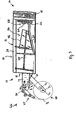
- Fig. 3 is a side elevational view of the cushioning conversion machine of Fig. 1, the machine being shown in a horizontal manner, loaded with stock material, and with an outer housing side wall removed for clarity of illustration.
- Fig. 4 is an exploded perspective view of the combination dancer roller and splicing plate device of Fig. 1.
- Fig. 5 is a downstream end view of the combination dancer roller and splicing plate device of Fig. 1 showing the combination in a rest position.
- Fig. 6 is a side view of the combination dancer roller and splicing plate device of Fig. 5.
- Fig. 7 is a downstream end view of the combination dancer roller and splicing plate device of Fig. 1 showing the combination activated by tension in the sheet stock material.
- Fig. 8 is a side view of the combination dancer roller and splicing plate device in the activated position thereof shown in Fig. 7.
- Fig. 9 is a side view of an adjuster bracket used in the combination dancer roller and splicing plate device of the present invention.
- Fig. 10 is a side view of another adjuster bracket used in the combination dancer roller and splicing plate device of the present invention.
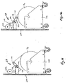
- Fig. 11 is a side elevational view of a supply cart and a combination dancer roller and splicing plate device in accordance with the present invention, showing the combination in a rest position.
- Fig. 12 is a side elevational view of the stock supply cart and combination dancer roller and splicing plate device of Fig. 11, showing the combination activated by tension in the sheet stock material.
-
- Referring now to the drawings in detail and initially to Figs. 1 through 3, a cushioning conversion machine is designated generally by
reference number 10. Thecushioning conversion machine 10 converts a sheet-like stock material, such as one or more layers of recyclable and reusable Kraft paper, into a dunnage product having, for example, lateral pillow-like portions separated by a thin central band. The dunnage product is used as an environmentally responsible protective packaging material typically used during shipping. - Referring more closely to Figs. 2 and 3, the
conversion machine 10 includes a conversion assembly, indicated generally at 12, having anupstream end 14 and adownstream end 16. The sheet-like stock material enters theconversion assembly 12 through an opening 18 at the upstream end thereof for passage through theconversion assembly 12 where it is converted into a strip of cushioning that exits from thedownstream end 16 of theconversion assembly 12. - The
conversion assembly 12 includes a former or formingassembly 26 and a feeding/connectingassembly 28 powered (energized) by afeed motor 30, for example an electric motor, through amotion transfer assembly 32. Downstream of the feeding/connecting assembly, there is provided a severing assembly 34 (for example, a cutting assembly) powered by suitable means, such as the illustrated motor andmotion transfer assembly 36. The formingassembly 26, feeding/connectingassembly 28 and severingassembly 34 are mounted to and/or in ahousing 38 in a well-known manner. The operation of theconversion machine 10 may be controlled by a controller, also in a well-known manner. - As will be apparent, other types of severing assemblies may be employed, such as those disclosed in commonly owned U.S. Patent Nos. 4,669,609 and 5,123,889. Also, other types of conversion assemblies may be employed for converting the sheet material to a three-dimensional shape of dunnage that is reduced to length by the severing assembly.
- The illustrated exemplary forming
assembly 26 includes a formingmember 44, such as a forming frame, and a convergingshaping chute 46. The formingassembly 26 causes an inward rolling or folding of the lateral edges of the sheetlike stock material to form a continuous strip of cushioning having lateral pillow-like portions. The shapingchute 46 includes longitudinally extending, transversely converging side walls 50 which preferably are curved or arcuate in transverse cross-section. As the sheet-like stock material is passed through the shapingchute 46, the side edges thereof are turned or rolled inwardly towards one another so that the inwardly turned or rolled edges form resilient pillow-like crumpled portions of stock material disposed in lateral abutting relationship as they emerge from the exit end of the shaping chute. The formingmember 44 coacts with the shapingchute 46 to ensure proper shaping and forming of the paper (or other suitable stock material), the forming member being operative to guide the central portion of the stock material along thebottom wall 54 of the shapingchute 46 for controlled inward rolling or folding of the side edge portions of the stock material. The formingmember 44 projects rearwardly (upstream) of the entry end of the shaping chute for proper guiding of the stock material into the shaping chute. The formingmember 44 also extends into the shaping chute with its forwardmost end disposed relatively close to theunderlying bottom wall 54 of the shaping chute adjacent the exit end of the shaping chute, as shown. - The invention encompasses different types of feeding/connecting assemblies which perform a feeding and/or connecting function. However, a preferred feeding/connecting
assembly 28 includes a pair of cooperating and opposed gears or gear-like members gears assembly 28, perform at least one and preferably two functions in the operation of themachine 10. One function is a "feeding" function, the gears pulling the stock material from a stock roll or other source thereof and then through the formingassembly 26. The material is then discharged by the feeding/connectingassembly 28 to the severingassembly 34. The second function preferably performed by the feeding/connectingassembly 28 is a connecting function. Specifically, the feeding/connectingassembly 28 connects the continuous strip by the two opposinggears - The connected strip travels downstream from the feeding/connecting
assembly 28 to the severingassembly 34 which severs, for example by cutting, the strip into a section of a desired length. The cut section then may travel through a post-cutting guide assembly such as in the manner described in commonly owned U.S. Patent No. 5,123,889, which includes a converging portion and rectangular tunnel portion. The coined or otherwise connected strip then emerges from the post-cutting guide assembly where an operator may remove the coined strip from themachine 10. - The
conversion machine 10 also includes astock supply assembly 66 which, as shown in the illustrated embodiment, includes a combination dancer roller and splicing plate device 67 (described in greater detail below) and a stock roll support assembly 68. The stock roll support assembly 68 includes a pair of laterally spaced apart mountingbrackets 69 secured to thehousing 38 of theconversion assembly 12. The upstream end ordistal end 70 of eachbracket 69 defines anopen slot 72 forming a cradle for rotatably receiving therein asupply rod 74 of astock roll 76. The geometry of theslot 72 allows the stock roll support assembly 68 to be mounted both in positions whereat theslot 72 opens toward the downstream direction and whereat theslot 72 opens toward the upstream direction. Additionally, themachine 10 may be tilted from one position to another (e.g. from a vertical position to a horizontal position) without having to remove thestock roll 76. - The
stock supply assembly 66 further includes a pair of laterally spaced apart mountingbrackets 78 secured to thehousing 38 of theconversion assembly 12. Thestock supply assembly 66 includes aconstant entry roller 80 that provides a non-varying point of entry for the sheet stock material from thestock roll 76. Thebrackets 78 also support therebetween a separating device which receives the sheet stock material from theconstant entry roller 80 and separates the multiple plies P1, P2, and P3 from one another via vertically spaced apart and transversely extendingseparator members 82, 84 and 86 prior to passing beneath the formingmember 44 and into the shapingchute 46. For further details concerning thestock supply assembly 66, reference may be had to U.S. Patent Application No. 09/109,247. For further details concerning theconstant entry roller 72 and theseparator members 82, 84, 86, reference may be had to U.S. Patent Application No.09/229,459. - Turning to Fig. 4, the combination dancer roller and
splicing plate device 67 includes a pair of substantially parallel and spaced apart dancer members, preferably in the form ofidler rollers side plates 116 which are interconnected by anintermediate support member 118. Thecombination 67 is rotatably biased between a rest position wherein theidler rollers idler rollers idler rollers stock roll 76 and theconstant entry roller 80. As described in greater detail below, theintermediate support member 118 preferably additionally functions as a splicing plate for providing a surface on which a succeeding roll of stock material may be spliced to a preceding nearly fully spent roll of stock material. - The combination dancer roller and
splicing plate device 67 is rotatably mounted at its lateral ends to a pair of mountingbrackets 120 that are connected to the respective mountingbrackets 78 of thestock supply assembly 66. Theidler rollers intermediate support member 118 extend transverse to the path of the stock material. Oneidler roller 110 is disposed upstream of thesupport member 118 and the otheridler roller 112 is disposed downstream of thesupport member 118. Theside plates 116 are preferably generally L-shaped and preferably integrally connected to the support member at substantially right angles thereto. - As shown in Figs. 6 and 8 of the illustrated embodiment, the
idler rollers idler rollers combination 67 to rotate in a counterclockwise direction. In this regard, theupstream idler roller 110 is mounted to the respective longer legs of the L-shapedside plates 116 so that thesupport member 118 lies within a plane that is tangent to theupstream idler roller 110. Thedownstream idler roller 112 is mounted to the respective shorter legs of theside plates 116 and is spaced apart from adownstream edge 122 of thesupport member 118 to form agap 124 for passage therethrough of the sheet stock material. As will be appreciated by the foregoing, thesupport member 118 is preferably disposed relative to theidler rollers idler rollers support member 118. This is shown, for example, in Figs. 6 and 8, where the stock material is shown in phantom lines. - An
elongated support sleeve 130 extends between and is connected to the L-shapedside plates 116. The ends of thesupport sleeve 130 extend through openings in theside plates 116 and are journalled inrespective bearings 132, preferably bronze bearings or bushings, which, in turn, are mounted inrespective openings 134 in the mountingbrackets 120. Thebearings 132 permit theidler rollers support member 118 to pivot about apivot axis 140 defined by the centerline or longitudinal axis of thesupport sleeve 130, which also passes through the centers of theopenings 134 of the mountingbrackets 120. - The
idler rollers intermediate support member 118,side plates 116 andsupport sleeve 130 are sized and oriented relative to one another so that thepivot axis 140 is coaxial with an axis passing through the center of gravity of the combination dancer roller andsplicing plate device 67. As a consequence, the weight of thecombination 67 has substantially no influence on the angular position, whether vertical, horizontal, or intermediate, of thecombination 67. - This allows the dimensioning of the components of the
combination 67 to differ from that shown in the several Figures so long as the objective of aligning thepivot axis 140 with the center of gravity of thecombination 67 is observed. Thus, if it is desired to increase or decrease the generally sinusoidal loop in the stock material created by thecombination 67 in a rest position (shown in phantom in Figs. 6 and 8), the spacing between theidler rollers pivot axis 140 or the longitudinal axis of thesupport sleeve 130. To compensate for this shift, thesupport sleeve 130 may be dimensioned or oriented to bring its longitudinal axis (i.e., the pivot axis 140) in alignment with the center of gravity. - The
support sleeve 130 further extends throughopenings respective adjuster brackets adjuster brackets splicing plate device 67 to a prescribed angular path. Eachadjuster bracket corresponding mounting bracket 134 via acover plate 160 andfasteners 162 such as screws. - A preloading member such as a spring device like a
torsion rod 170 extends through and is connected to thesupport sleeve 130 to provide rotational bias in the combination dancer roller andsplicing plate device 67. At one end (the left end in Fig. 4)thetorsion rod 170 is bent at 90 degrees to form atail portion 174 that seats within a correspondingly sized radially extending groove 176 (Fig. 10) defined by theadjuster bracket 158. At its other end (the right end in Fig. 4) thetorsion rod 170 is fixedly connected to thesupport sleeve 130 for rotation therewith. This is accomplished by, for example, thetorsion rod 170 including an eye hook (not shown) and thesupport sleeve 130 including a transversely mountedpin 177 that extends through the eye hook (and apertures not shown in the support sleeve 130) thereby to secure thetorsion rod 170 to thesupport sleeve 130. It will be appreciated that thetorsion rod 170 resists angular rotation of the right-side fixed connection (the support sleeve 130) relative to the left-side fixed connection (the adjuster bracket 158) which, in effect, causes a resistance, or bias, to counterclockwise rotation of the combination dancer roller andsplicing plate device 67 as viewed in Figs. 6 and 8. It is this rotational bias that substantially absorbs increases, or spikes, in the tension of the sheet stock material as the stock material passes over theidler rollers - In operation, the
torsion rod 170 urges thesupport sleeve 130, and therefore thesupport member 118 andidler rollers idler rollers conversion machine 10 is not operating or otherwise operating at a low speed. Increases in the tension of the stock material may cause the idler rollers 110,112 andsupport member 118 to pivot about the rotational axis 140 (in a counterclockwise direction in Fig. 6) against the bias of thetorsion rod 170. Thetorsion rod 170 substantially absorbs the increased tension and thereby helps to maintain a greater uniformity of tension on the stock material. As the tension in the stock material decreases due to, for example, theconversion machine 10 being reduced in speed, the stock roll may overrun and cause slack in the stock material. This slack may be taken up by the combination dancer roller andsplicing plate device 67 as thetorsion rod 170 urges thecombination 67 back to its rest position. - Referring to Fig. 11, the adjuster bracket 156 (shown in the right side of Fig. 4) operates as a detent mechanism or a limiter to limit rotational movement of the combination dancer roller and
splicing plate device 67 by restricting rotational movement of thesupport sleeve 130 via the transversely mountedpin 177 therein to a prescribed range of angular rotation. To accomplish this, the transversely mountedpin 177 is sized slightly greater in length than the diameter of thesupport sleeve 130 so as to form a pair of radially extending limiter tabs 178 (not shown in detail) that cooperate with theadjuster bracket 156. To this end, theopening 150 in theadjuster bracket 156 defines a pair of opposed and equally spaced apartarcuate tabs 180 and, in alternate relation thereto, a pair of opposed and equally spaced apartarcuate slots 182. In other words, theopening 150 comprises a narrow diametrical section and a wide diametrical section. The narrow section has a diameter less than the length of the transversely mountedpin 177 in thesupport sleeve 130 and the wide section has a diameter greater than the length of thepin 177 for cooperatively receiving therein thelimiter tabs 178 of thepin 177. In operation, thelimiter tabs 178 pivot about thepivot axis 140 of thesupport sleeve 130 within thearcuate slots 182 but are limited in motion, or blocked, by thearcuate tabs 180. In the illustrated embodiment, thearcuate tabs 180 andarcuate slots 182 comprise 90 degree segments and, therefore, the range of angular rotation of thesupport sleeve 130 and, consequently, the combination dancer roller andsplicing plate device 67 is limited to 90 degrees. It will be appreciated that this range may be made greater or less than 90 degrees as desired by changing the relative sizes of thearcuate tabs 180 andarcuate slots 182 of theadjuster bracket 156. - The
adjuster bracket 156 further includes a pair ofarcuate slots 190 and, in a similar manner, theadjuster bracket 158 includes a pair ofarcuate slots 192 through which thefasteners 162 extend for selectively securing the combination dancer roller andsplicing plate 67 to a desirable orientation relative to theconversion assembly 12 and/or for adjusting the torsional bias of thetorsion rod 170. More particularly, by loosening thefasteners 162, theadjuster brackets combination 67 may be rotatably adjusted relative to each another, thereby permitting the combination dancer roller andsplicing plate device 67 to be rotatably adjusted to a desired orientation and/or the torsional bias in thetorsion rod 170 to be increased or decreased as desired. - This is particularly useful, for example, if it is desired to rotate the
cushioning conversion machine 10 to a different orientation, in which case the combination dancer roller andsplicing plate device 67 may be rotated, or reoriented, to a new position relative to themachine 10 to optimize its tension absorbing and slack reduction features. This may be accomplished by maximizing the size of the generally sinusoidal loop created in the stock material when thecombination 67 is in a rest position (for example, as shown in Fig. 6) and by ensuring that the stock material travels in a substantially linear path between thestock roll 76 and theconstant entry roller 80 when thecombination 67 is in one of its activated positions (for example, as shown in Fig. 8). - The reorienting of the
combination 67 to achieve a similar loop size and linear path has substantially little or no influence on the tension reducing and/or slack take up characteristics of thecombination 67 since, as described above, thepivot axis 140 of thecombination 67 is coaxial with the center of gravity thereof. In other words, since the weight distribution of thecombination 67 about thepivot axis 140 remains unchanged, it has substantially little or no influence on the operation of thecombination 67. It will be appreciated, then, that the combination dancer roller andsplicing plate device 67 may accommodate different machine orientations ranging from vertical to horizontal and beyond. - The
adjuster brackets combination 67 to be changed as desired for a stock material having a greater or lesser strength or a greater or lesser resistance to tearing by positioning theadjuster brackets fasteners 162, so that thetorsion rod 170 has a higher or tower preload. Of course, one skilled in the art will appreciate that the amount of preload will depend on the size of the stock roll of material and the strength of the material layers thereof. In addition, by rotating theadjuster bracket 156, changes may be made to the orientation of the prescribed range of angular rotation of the combination dancer roller andsplicing plate device 67. - As alluded to above, the
intermediate support member 118 may additionally function as a splicing plate for providing a surface on which a succeeding roll of stock material may be spliced to a preceding roll nearly fully spent roll of stock material. A preferred configuration of the combination dancer roller andsplicing plate device 67 for splicing purposes is when thesupport member 118 and the splicing surface provided thereby is facing outwardly in an easily accessible manner. This configuration is illustrated in Fig. 8 wherein the combination is shown activated by tension in the stock material. - The combination dancer roller and
splicing plate device 67 may be locked in this position by a suitable locking member, for example, a locking bolt (not shown) disposed at one or more of the ends of thecombination 67. In a locked position, thecombination 67 may be fixed relative to theconversion assembly 12 thereby to permit splicing of a succeeding roll of stock material to a preceding roll of stock material in themachine 10. When splicing is completed, the locking bolt may be unlocked to allow the combination dancer roller andsplicing plate device 67 to return to its rest position whereat thecombination 67 may take up slack in the spliced sheet stock material. - Of course, the
aforedescribed adjuster brackets support member 118 to a desired angle for simplifying accessibility to splicing. This may be accomplished by orienting thesupport member 118 outwardly and maintaining the ability to position thesupport member 118 relative to the sheet stock material so that the material travels in a substantially linear path adjacent to and/or juxtaposed to thesupport member 118 for splicing purposes (for example, as shown in Fig. 8). - It is noted that while the combination dancer roller and
splicing plate device 67 shown in Figs. 4 through 8 forms part of thecushioning conversion machine 10, thecombination 67 may alternatively comprise a mechanism separate from that of theconversion machine 10 as shown, for example, in Figs. 11 and 12. The description above of the various components and functions of the combination dancer roller andsplicing plate device 67 is applicable to such an arrangement and, in this regard, like reference numerals correspond to like components in the several Figures. - In Figs. 11 and 12, the
combination 67 is shown being used as a modular device with astock roll cart 200. More particularly, in Fig. 11 thecombination 67 is shown in a rest position and in Fig. 12 thecombination 67 is shown activated by tension in the sheet stock material. Here, an additionalidler roller 202 is provided over which the sheet stock material passes before being fed through theconversion machine 10. Theidler roller 202 may be attached to asupport member 204 which may comprise a separate stand, a frame member of the conversion machine, or even a support member of thecart 200. - A separate, or modular, combination dancer roller and
splicing plate device 67, as shown in Figs. 11 and 12, is particularly useful for vertically oriented machines since such machines are otherwise difficult to approach for splicing purposes. For example, if the angular orientation of thecushioning conversion machine 10 shown in Fig. 3 is changed in a counterclockwise manner from its horizontal orientation to a vertical orientation, thesupport member 118, and the splicing surface thereof, would be facing in a downwardly direction. By incorporating the additionalidler roller 202 in the aforedescribed manner and relocating the combination dancer roller andsplicing plate device 67 so that the sheet stock material travels from theidler roller 202 to theconstant entry roller 80, thecombination 67 may be oriented so that thesupport member 118 and its splicing surface face substantially upwardly for simplifying the approaching thereof for splicing purposes. - Although the invention has been shown and described with respect to certain preferred embodiments, equivalent alterations and modifications will occur to others skilled in the art upon reading and understanding this specification and the annexed drawings. In particular regard to the various functions performed by the above described integers (components, assemblies, devices, compositions, etc.), the terms (including a reference to a "means") used to describe such integers are intended to correspond, unless otherwise indicated, to any integer which performs the specified function of the described integer (i.e., that is functionally equivalent), even though not structurally equivalent to the disclosed structure which performs the function in the herein illustrated exemplary embodiment or embodiments of the invention. In addition, while a particular feature of the invention may have been described above with respect to only one of several illustrated embodiments, such feature may be combined with one or more other features of the other embodiments, as may be desired and advantageous for any given or particular application.
Claims (38)
- A cushioning conversion machine comprising a conversion assembly which converts multi-ply stock material into a three-dimensional cushioning product and a dancer device operative for helping maintain a greater uniformity of tension on the stock material being fed through the conversion assembly, wherein a portion of the dancer device forms a splicing plate for providing a surface on which a succeeding roll of stock material may be spliced to a preceding nearly fully spent roll of stock material.
- A cushioning conversion machine as set forth in claim 1, wherein the dancer device is selectively lockable to a splicing position to permit splicing of stock material on the splicing plate.
- A cushioning conversion machine as set forth in claim 1, wherein the dancer device includes a detent mechanism for limiting movement of the dancer device.
- A cushioning conversion machine as set forth in claim 1, wherein the dancer device includes at least one adjuster member for selectively securing the dancer device to an orientation relative to the conversion assembly.
- A cushioning conversion machine as set forth in claim 1, further comprising a locking member selectively operable between a locked position for securing the dancer device relative to the conversion assembly and an unlocked position for permitting movement of the dancer device relative to the conversion assembly.
- In combination, a cushioning conversion machine and a dancer device, the conversion machine comprising a conversion assembly which converts multi-ply stock material into a three-dimensional cushioning product, wherein the dancer device is operative to help maintain a greater uniformity of tension on the stock material being fed through the conversion assembly, and wherein a portion of the dancer device forms a splicing plate for providing a surface on which a succeeding roll of stock material may be spliced to a preceding nearly fully spent roll of stock material.
- The combination as set forth in claim 6, wherein the dancer device is supported by a cart.
- The combination as set forth in claim 6, wherein the dancer device is supported by a stand.
- A dancer device for use in a cushioning conversion machine including a conversion assembly which converts multi-ply stock material into a three-dimensional cushioning product, wherein the dancer device helps maintain a greater uniformity of tension on stock material being fed through the conversion assembly and wherein a portion of the dancer device forms a splicing plate for providing a surface on which a succeeding roll of stock material may be spliced to a preceding nearly fully spent roll of stock material.
- A cushioning conversion machine comprising a conversion assembly which converts multi-ply stock material into a three-dimensional cushioning product and a dancer device operative for helping maintain a greater uniformity of tension on the stock material being fed through the conversion assembly, the dancer device being rotatably biased about a pivot axis that is coaxial with an axis passing through the center of gravity of the dancer device.
- A cushioning conversion machine as set forth in claim 10, wherein a portion of the dancer device forms a splicing plate for providing a surface on which a succeeding roll of stock material may be spliced to a preceding nearly fully spent roll of stock material.
- A cushioning conversion machine as set forth in claim 10, wherein the dancer device is rotatably biased from one or more activated positions whereat an increase in tension in the stock material may be substantially absorbed by the rotational bias to a rest position whereat slack in the stock material may be taken up by the rotational bias.
- A cushioning conversion machine as set forth in claim 10, wherein the dancer device includes a detent mechanism for limiting rotational movement of the dancer device.
- A cushioning conversion machine as set forth in claim 10, wherein the dancer device includes at least one adjuster member for selectively securing the dancer device to an orientation relative to the conversion assembly.
- A cushioning conversion machine as set forth in claim 10, wherein the dancer device includes at least one adjuster member for selectively adjusting the rotational bias of the dancer device.
- A cushioning conversion machine as set forth in claim 10, further comprising a preload member for providing rotational bias in the dancer device about the pivot axis.
- A cushioning conversion machine as set forth in claim 16, wherein the preload member extends substantially coaxial with the pivot axis.
- A cushioning conversion machine as set forth in claim 10, further comprising a locking member selectively operable between a locked position for securing the dancer device relative to the conversion assembly and an unlocked position for permitting rotatable movement of the dancer device about the pivot axis.
- In combination, a cushioning conversion machine and a dancer device, the conversion machine comprising a conversion assembly which converts multi-ply stock material into a three-dimensional cushioning product, wherein the dancer device is operative to help maintain a greater uniformity of tension on the stock material being fed through the conversion assembly, and wherein the dancer device is rotatably biased about a pivot axis that is coaxial with an axis passing through the center of gravity of the dancer device.
- The combination as set forth in claim 19, wherein the dancer device is supported by a cart.
- The combination as set forth in claim 19, wherein the dancer device is supported by a stand.
- A dancer device for use in a cushioning conversion machine comprising a conversion assembly which converts multi-ply stock material into a three-dimensional cushioning product, wherein the dancer device helps maintain a greater uniformity of tension on the stock material being fed through the conversion assembly and wherein the dancer device is rotatably biased about a pivot axis that is coaxial with an axis passing through the center of gravity of the dancer device.
- A cushioning conversion machine comprising a conversion assembly which converts multi-ply stock material into a three-dimensional cushioning product and a dancer device operative for helping maintain a greater uniformity of tension on the stock material being fed through the conversion assembly, the dancer device including first and second substantially parallel and spaced apart dancer members transverse to the path of stock material and over which the stock material passes, the members being pivotable about a pivot axis in response to changes in tension of the stock material.
- A cushioning conversion machine as set forth in claim 23, wherein a portion of the dancer device forms a splicing plate for providing a surface on which a succeeding roll of stock material may be spliced to a preceding nearly fully spent roll of stock material.
- A cushioning conversion machine as set forth in claim 24, wherein the splicing plate is disposed relative to the dancer members so that as the stock material passes over the dancer members the stock material is substantially adjacent to the splicing plate.
- A cushioning conversion machine as set forth in claim 23, wherein the dancer device is rotatably biased from one or more activated positions whereat an increase in tension in the stock material may be substantially absorbed by the rotational bias to a rest position whereat slack in the stock material may be taken up by the rotational bias.
- A cushioning conversion machine as set forth in claim 26, wherein in the rest position the dancer members form a generally sinusoidal loop in the stock material for taking up slack therein.
- A cushioning conversion machine as set forth in claim 26, wherein in the one or more activated positions the dancer members guide the stock material along a substantially linear path.
- A cushioning conversion machine as set forth in claim 23, wherein the dancer device includes a detent mechanism for limiting rotational movement of the dancer device to a prescribed angular path.
- A cushioning conversion machine as set forth in claim 23, wherein the dancer device includes at least one adjuster member for selectively securing the dancer device to an orientation relative to the conversion assembly.
- A cushioning conversion machine as set forth in claim 26, wherein the dancer device includes at least one adjuster member for selectively adjusting the rotational bias of the dancer device.
- A cushioning conversion machine as set forth in claim 23, further comprising a preload member for providing rotational bias in the dancer members about the pivot axis.
- A cushioning conversion machine as set forth in claim 32, wherein the preload member extends substantially coaxial with the pivot axis.
- A cushioning conversion machine as set forth in claim 23, further comprising a locking member selectively operable between a locked position for securing the dancer device relative to the conversion assembly and an unlocked position for permitting pivotable movement of the dancer members about the pivot axis.
- In combination, a cushioning conversion machine and a dancer device, the conversion machine comprising a conversion assembly which converts multi-ply stock material into a three-dimensional cushioning product, wherein the dancer device is operative to help maintain a greater uniformity of tension on the stock material being fed through the conversion assembly, and wherein the dancer device includes first and second substantially parallel and spaced apart dancer members transverse to the path of stock material and over which the stock material passes, the members being pivotable about a pivot axis in response to changes in tension of the stock material.
- The combination as set forth in claim 35, wherein the dancer device is supported by a cart.
- The combination as set forth in claim 35, wherein the dancer device is supported by a stand.
- A dancer device for use in a cushioning conversion machine comprising a conversion assembly which converts multi-ply stock material into a three-dimensional cushioning product, wherein the dancer device helps maintain a greater uniformity of tension on the stock material being fed through the conversion assembly and the dancer device includes first and second substantially parallel and spaced apart dancer members transverse to the path of stock material and over which the stock material passes, the members being pivotable about a pivot axis in response to changes in tension of the stock material.
Applications Claiming Priority (2)
| Application Number | Priority Date | Filing Date | Title |
|---|---|---|---|
| US13970299P | 1999-06-17 | 1999-06-17 | |
| US139702P | 1999-06-17 |
Publications (2)
| Publication Number | Publication Date |
|---|---|
| EP1066955A2 true EP1066955A2 (en) | 2001-01-10 |
| EP1066955A3 EP1066955A3 (en) | 2001-08-01 |
Family
ID=22487907
Family Applications (1)
| Application Number | Title | Priority Date | Filing Date |
|---|---|---|---|
| EP00305137A Withdrawn EP1066955A3 (en) | 1999-06-17 | 2000-06-16 | Cushioning conversion machine with combination dancer roller and splicing plate device |
Country Status (1)
| Country | Link |
|---|---|
| EP (1) | EP1066955A3 (en) |
Cited By (5)
| Publication number | Priority date | Publication date | Assignee | Title |
|---|---|---|---|---|
| EP1645406A1 (en) * | 2005-02-17 | 2006-04-12 | Reinhard Keller | Machine for making paper cushioning products |
| WO2009029522A3 (en) * | 2007-08-24 | 2009-05-07 | Ranpak Corp | Dunnage conversion system and method with stock material splicing |
| US7722519B2 (en) | 2004-08-20 | 2010-05-25 | Ranpak Corporation | Dunnage conversion machine and method |
| US8167783B2 (en) | 2006-04-11 | 2012-05-01 | Pack-Tiger Gmbh | Machine for the manufacture of paper padding |
| CN103697866A (en) * | 2013-12-09 | 2014-04-02 | 长江勘测规划设计研究有限责任公司 | Coaxial protection device for field measurement and spanner thereof |
Citations (2)
| Publication number | Priority date | Publication date | Assignee | Title |
|---|---|---|---|---|
| WO1996040496A1 (en) * | 1995-06-07 | 1996-12-19 | Ranpak Corp. | Machine for converting stock material into a cushioning product |
| WO1999004963A1 (en) * | 1997-07-28 | 1999-02-04 | Ranpak Corp. | Cushioning conversion machine with power infeed |
-
2000
- 2000-06-16 EP EP00305137A patent/EP1066955A3/en not_active Withdrawn
Patent Citations (2)
| Publication number | Priority date | Publication date | Assignee | Title |
|---|---|---|---|---|
| WO1996040496A1 (en) * | 1995-06-07 | 1996-12-19 | Ranpak Corp. | Machine for converting stock material into a cushioning product |
| WO1999004963A1 (en) * | 1997-07-28 | 1999-02-04 | Ranpak Corp. | Cushioning conversion machine with power infeed |
Cited By (6)
| Publication number | Priority date | Publication date | Assignee | Title |
|---|---|---|---|---|
| US7722519B2 (en) | 2004-08-20 | 2010-05-25 | Ranpak Corporation | Dunnage conversion machine and method |
| EP1645406A1 (en) * | 2005-02-17 | 2006-04-12 | Reinhard Keller | Machine for making paper cushioning products |
| US8167783B2 (en) | 2006-04-11 | 2012-05-01 | Pack-Tiger Gmbh | Machine for the manufacture of paper padding |
| WO2009029522A3 (en) * | 2007-08-24 | 2009-05-07 | Ranpak Corp | Dunnage conversion system and method with stock material splicing |
| CN103697866A (en) * | 2013-12-09 | 2014-04-02 | 长江勘测规划设计研究有限责任公司 | Coaxial protection device for field measurement and spanner thereof |
| CN103697866B (en) * | 2013-12-09 | 2016-05-04 | 长江勘测规划设计研究有限责任公司 | The coaxial protective device of field measurement and spanner thereof |
Also Published As
| Publication number | Publication date |
|---|---|
| EP1066955A3 (en) | 2001-08-01 |
Similar Documents
| Publication | Publication Date | Title |
|---|---|---|
| US6436511B1 (en) | Cushioning conversion machine, method and product | |
| US6974407B2 (en) | Cushioning conversion machine and method | |
| US5924971A (en) | Cushioning conversion machine for converting sheet-like stock material into a cushioning product | |
| CA2494020C (en) | Compact apparatus and system for creating and dispensing cushioning dunnage | |
| EP1827809B1 (en) | Dunnage conversion machine and method | |
| EP1047545B1 (en) | Cushioning conversion machine and method | |
| EP0688664A2 (en) | Downsized cushioning dunnage conversion machine and packaging systems employing the same | |
| EP2874806A1 (en) | Apparatus and method for dispensing cushioning wrap material | |
| US6168560B1 (en) | Cushioning conversion machine and method with pad transferring device | |
| US6491614B1 (en) | Cushioning conversion machine with tension control | |
| US7083560B2 (en) | Cushioning conversion machine having heavy duty characteristics | |
| EP1066955A2 (en) | Cushioning conversion machine with combination dancer roller and splicing plate device | |
| US20070021286A1 (en) | Cushioning conversion machine having heavy duty characteristics | |
| EP0998384B1 (en) | Cushioning conversion machine with power infeed | |
| WO2018175742A1 (en) | Dunnage conversion machine having a variable spacing for expandable slit-sheet stock material | |
| US5713825A (en) | Cushioning conversion machine and method for converting stock material into a dunnage product having a casing and a stuffing within the casing | |
| WO1996040494A1 (en) | Cushioning conversion system having horizontally pivotable mounting relative to a stand | |
| EP0831992A4 (en) | ||
| CA3073591C (en) | Dunnage conversion system and method for expanding expandable sheet material | |
| US7041043B2 (en) | Cushioning conversion machine and method with plural constant entry rollers and moving blade shutter | |
| US6210310B1 (en) | Cushioning conversion machine and method with enhanced stock separation and forming | |
| WO2001017763A2 (en) | Cushioning conversion machine having heavy duty characteristics | |
| EP1310355B1 (en) | Cushioning Conversion Device | |
| EP1197321A2 (en) | Cushioning conversion machine and method with stock roll brake |
Legal Events
| Date | Code | Title | Description |
|---|---|---|---|
| PUAI | Public reference made under article 153(3) epc to a published international application that has entered the european phase |
Free format text: ORIGINAL CODE: 0009012 |
|
| AK | Designated contracting states |
Kind code of ref document: A2 Designated state(s): CH DE FR GB LI NL |
|
| AX | Request for extension of the european patent |
Free format text: AL;LT;LV;MK;RO;SI |
|
| PUAL | Search report despatched |
Free format text: ORIGINAL CODE: 0009013 |
|
| AK | Designated contracting states |
Kind code of ref document: A3 Designated state(s): AT BE CH CY DE DK ES FI FR GB GR IE IT LI LU MC NL PT SE |
|
| AX | Request for extension of the european patent |
Free format text: AL;LT;LV;MK;RO;SI |
|
| 17P | Request for examination filed |
Effective date: 20020201 |
|
| AKX | Designation fees paid |
Free format text: CH DE FR GB LI NL |
|
| 17Q | First examination report despatched |
Effective date: 20030207 |
|
| STAA | Information on the status of an ep patent application or granted ep patent |
Free format text: STATUS: THE APPLICATION IS DEEMED TO BE WITHDRAWN |
|
| 18D | Application deemed to be withdrawn |
Effective date: 20030618 |