EP1061984B1 - Tracheal breathing apparatus - Google Patents
Tracheal breathing apparatus Download PDFInfo
- Publication number
- EP1061984B1 EP1061984B1 EP99939165A EP99939165A EP1061984B1 EP 1061984 B1 EP1061984 B1 EP 1061984B1 EP 99939165 A EP99939165 A EP 99939165A EP 99939165 A EP99939165 A EP 99939165A EP 1061984 B1 EP1061984 B1 EP 1061984B1
- Authority
- EP
- European Patent Office
- Prior art keywords
- fold
- tracheal
- ventilating device
- cuff
- balloon
- Prior art date
- Legal status (The legal status is an assumption and is not a legal conclusion. Google has not performed a legal analysis and makes no representation as to the accuracy of the status listed.)
- Expired - Lifetime
Links
Images


Classifications
-
- A—HUMAN NECESSITIES
- A61—MEDICAL OR VETERINARY SCIENCE; HYGIENE
- A61M—DEVICES FOR INTRODUCING MEDIA INTO, OR ONTO, THE BODY; DEVICES FOR TRANSDUCING BODY MEDIA OR FOR TAKING MEDIA FROM THE BODY; DEVICES FOR PRODUCING OR ENDING SLEEP OR STUPOR
- A61M16/00—Devices for influencing the respiratory system of patients by gas treatment, e.g. mouth-to-mouth respiration; Tracheal tubes
- A61M16/04—Tracheal tubes
- A61M16/0402—Special features for tracheal tubes not otherwise provided for
- A61M16/042—Special features for tracheal tubes not otherwise provided for with separate conduits for in-and expiration gas, e.g. for limited dead volume
-
- A—HUMAN NECESSITIES
- A61—MEDICAL OR VETERINARY SCIENCE; HYGIENE
- A61M—DEVICES FOR INTRODUCING MEDIA INTO, OR ONTO, THE BODY; DEVICES FOR TRANSDUCING BODY MEDIA OR FOR TAKING MEDIA FROM THE BODY; DEVICES FOR PRODUCING OR ENDING SLEEP OR STUPOR
- A61M16/00—Devices for influencing the respiratory system of patients by gas treatment, e.g. mouth-to-mouth respiration; Tracheal tubes
- A61M16/04—Tracheal tubes
- A61M16/0434—Cuffs
- A61M16/0436—Special fillings therefor
- A61M16/0438—Liquid-filled
-
- A—HUMAN NECESSITIES
- A61—MEDICAL OR VETERINARY SCIENCE; HYGIENE
- A61M—DEVICES FOR INTRODUCING MEDIA INTO, OR ONTO, THE BODY; DEVICES FOR TRANSDUCING BODY MEDIA OR FOR TAKING MEDIA FROM THE BODY; DEVICES FOR PRODUCING OR ENDING SLEEP OR STUPOR
- A61M16/00—Devices for influencing the respiratory system of patients by gas treatment, e.g. mouth-to-mouth respiration; Tracheal tubes
- A61M16/04—Tracheal tubes
- A61M16/0434—Cuffs
- A61M16/0443—Special cuff-wall materials
-
- A—HUMAN NECESSITIES
- A61—MEDICAL OR VETERINARY SCIENCE; HYGIENE
- A61M—DEVICES FOR INTRODUCING MEDIA INTO, OR ONTO, THE BODY; DEVICES FOR TRANSDUCING BODY MEDIA OR FOR TAKING MEDIA FROM THE BODY; DEVICES FOR PRODUCING OR ENDING SLEEP OR STUPOR
- A61M16/00—Devices for influencing the respiratory system of patients by gas treatment, e.g. mouth-to-mouth respiration; Tracheal tubes
- A61M16/04—Tracheal tubes
- A61M16/0434—Cuffs
- A61M16/0445—Special cuff forms, e.g. undulated
-
- A—HUMAN NECESSITIES
- A61—MEDICAL OR VETERINARY SCIENCE; HYGIENE
- A61M—DEVICES FOR INTRODUCING MEDIA INTO, OR ONTO, THE BODY; DEVICES FOR TRANSDUCING BODY MEDIA OR FOR TAKING MEDIA FROM THE BODY; DEVICES FOR PRODUCING OR ENDING SLEEP OR STUPOR
- A61M16/00—Devices for influencing the respiratory system of patients by gas treatment, e.g. mouth-to-mouth respiration; Tracheal tubes
- A61M16/04—Tracheal tubes
- A61M16/0434—Cuffs
- A61M16/0454—Redundant cuffs
- A61M16/0456—Redundant cuffs one cuff within another
-
- A—HUMAN NECESSITIES
- A61—MEDICAL OR VETERINARY SCIENCE; HYGIENE
- A61M—DEVICES FOR INTRODUCING MEDIA INTO, OR ONTO, THE BODY; DEVICES FOR TRANSDUCING BODY MEDIA OR FOR TAKING MEDIA FROM THE BODY; DEVICES FOR PRODUCING OR ENDING SLEEP OR STUPOR
- A61M16/00—Devices for influencing the respiratory system of patients by gas treatment, e.g. mouth-to-mouth respiration; Tracheal tubes
- A61M16/04—Tracheal tubes
- A61M16/0434—Cuffs
- A61M16/0454—Redundant cuffs
- A61M16/0459—Redundant cuffs one cuff behind another
-
- A—HUMAN NECESSITIES
- A61—MEDICAL OR VETERINARY SCIENCE; HYGIENE
- A61M—DEVICES FOR INTRODUCING MEDIA INTO, OR ONTO, THE BODY; DEVICES FOR TRANSDUCING BODY MEDIA OR FOR TAKING MEDIA FROM THE BODY; DEVICES FOR PRODUCING OR ENDING SLEEP OR STUPOR
- A61M16/00—Devices for influencing the respiratory system of patients by gas treatment, e.g. mouth-to-mouth respiration; Tracheal tubes
- A61M16/04—Tracheal tubes
- A61M16/0402—Special features for tracheal tubes not otherwise provided for
- A61M16/0415—Special features for tracheal tubes not otherwise provided for with access means to the stomach
Definitions
- the invention relates to a tracheal ventilation device, in particular Tracheal tube or tracheal cannula that connects the trachea to a patient's ventilation closed as tightly as possible, with one blocking the trachea below the glottis Cuff bladder through which a ventilation cannula is passed, the cuff bladder in the filled, freely unfoldable state is larger than in the filled Condition placed in the trachea, and consists of flexible soft film material, , the cuff bladder can be applied to the trachea by drapery.
- a tracheal ventilation device in particular Tracheal tube or tracheal cannula that connects the trachea to a patient's ventilation closed as tightly as possible, with one blocking the trachea below the glottis Cuff bladder through which a ventilation cannula is passed, the cuff bladder in the filled, freely unfoldable state is larger than in the filled Condition placed in the trachea, and consists of flexible soft film material, , the
- a tracheal ventilator proposed in US-A-3,766,927 Genus has a cuff bladder, which is larger than the trachea and from the inside applying pressure to the trachea.
- the foil material of the cuff bladder has a thickness of 0.0254 mm, alternatively a thickness of 0.0762 mm is also proposed becomes.
- US-A-3 610 247 discloses a tracheal ventilator, which is of the Structure corresponds to the device disclosed in US-A-3,766,927.
- she has a cuff bladder made of preferably semi-permeable material, which at its Can deliver an anesthetic to the wall of the trachea.
- Wall thicknesses of the film are given as examples of 0.05, 0.07 and 0.1 mm theoretically, films thinner than 0.05 mm can also be used.
- Regarding the Seal shows this device a behavior similar to US-A-3,766,927.
- the cuff bladder expands when inflated it is elastic and lies close to the wall without folds the trachea. If the filling pressure of the cuff bladder exceeds the blood pressure of the Mucous membrane supplying the vascular bed, so serious structural Lesions of the epithelium may result. Especially in long-term incubated patients should the filling pressure in the cuff bladder at the lowest possible, the mucosal perfusion non-impairing level. However, the filling pressure chosen too low, this can lead to leakage of bacterially populated pharynx the cuff bladder and thus for colonization and infection of the lung tissue to lead.
- the invention has for its object a tracheal ventilation device to improve the genre mentioned in such a way that a patient with it can be intubated for as long as possible at low pressures, the risk of infection should be low.
- a generic Tracheal ventilation device which is characterized in that the Wall thickness of the film is less than or equal to 0.02 mm and the cuff bubble is designed such that the fold eyelet that arises at the dead end of a fold has a small diameter that allows the free flow of the secretion through counteracts the wrinkle eyelet.
- the flow of secretions can be controlled by the specific training of Influence cuff folding in the area of a fold eyelet, i.e. on the fold base. While it was previously assumed in the prior art that cuff bubbles with drapery because of the low filling pressure not sufficiently close to the Trachea may be present, the invention provides a way to inhibit the Secretion flow in the area of a fold eyelet. Form when blocking the cuff at the deep end of the fold, at the base of the fold, fold eyelets, which one such have a small diameter that the flow of secretion is slowed down or ideally comes to a standstill. This can already be the case with film thicknesses from or below 0.002 mm enter.
- the eyelet is preferably formed in a capillary size. Adequate results then result Adhesive forces of the secretion on the fold eyelet or a sufficient viscosity-dependent resistance of the secretion to reduce the flow of secretion.
- the flow velocity in the capillary-sized fold eyelet is then less than the theoretically possible speed without adhesion or viscosity forces, so that less secretion flows through over time.
- the diameter the eyelet should be designed so small that the flow of secretion comes to a complete standstill.
- the diameter of the fold eyelet can be particularly advantageously less than 0.11 or 0.05 mm. Below 0.1 mm there is already a certain inhibition of the Secretion flow rate through the eyelet. With a wrinkle eye diameter of less than 0.05 mm the secretion flow slows down and comes close to to a halt.
- the wall thickness of the film material can advantageously be chosen to be so thin that that the inner radius of the fold eyelets that form is physiologically acceptable Filling pressure reduced to such an extent that secretions are prevented from flowing freely becomes.
- the wall thicknesses of conventional cuff bubbles are mostly in the range of 0.06 up to 0.1 mm.
- the wall thickness of the film is approximately 0.01 to 0.005 mm.
- a wall thickness of 0.01 to 0.005 mm you can use a soft, flexible Already a satisfactory inhibition of the secretion flow or its stasis in the Area of the fold base can be reached.
- the film material can be the cuff bladder for example made of polyethylene terephthalate (PETP), low-density polyethylene (LDPE), Polyvinyl chloride (PCV) or polyurethane (PU) exist. These materials are compatible with the body and are particularly suitable in thin-walled processing good for forming a tightly fitting drapery. Copolymer mecanicischept to modify the material properties are conceivable (e.g. LDPE-EVA).
- PETP polyethylene terephthalate
- LDPE low-density polyethylene
- PCV Polyvinyl chloride
- PU polyurethane
- the cuff bladder may be made of a self-adhesive material its adhesion to reduce the clear diameter of an eyelet on the base of the folds contributes.
- the wall thickness of the film can be in the area of the folds be thinner than in the wrinkle-free area immediately adjacent to the tracheal mucosa Area. Wrinkles preferably form in the thin-walled cuff area, because the film is easier to deform here.
- the fold base can be due to the lesser Form wall thickness of eyelets of smaller diameter. In the thick-walled cuff area the cuff coat behaves somewhat more rigidly between the folds, so that it is only rounded lies against the wall of the trachea.
- the fold walls lying opposite one another can be connected to each other in the area near the base of the folds.
- the liaison office can be provided immediately adjacent to the forming eyelet be so that through them the size of the fold eyelet to a desired Diameter is to be set.
- the opposite fold walls at the dead end of the Fold, filling the eyelet be connected to each other and thus the flow of secretion is safe prevention.
- the opposing fold walls of a fold with one another are conceivable be welded or glued.
- variable fold section in which the opposite fold walls are not physically connected.
- the cuff bladder of the trachea the concept, can fold with a variable depth of fold Adjust residual cuff coat, in size and shape.
- the tamponler bladder is recommended also to be designed with residual volume, i.e. their volume with free development should exceed the volume of the inner larynx to be filled.
- the Tampon bladder corresponds to the sealing principles according to the invention and gentle cuff bladder design. The formation of the described capillary This prevents structures.
- the invention proposes the addition of an additional mechanical cuff to the cuff sealing, the previously described design principles for sealing and Tissue bladder corresponding to tissue compatibility.
- the tampon bladder can be pressurized with a minimum filling pressure of preferably 10 to 15 mbar, which is only the task of unfolding the thin, sealing bladder wall Has.
- the tampon bladder can be arranged and related to the tube shaft or for fixing cuff the embodiments described in DE 196 38 935 correspond.
- the fixing cuff on the caudal side of the Device, and the tampon bladder is mounted cranially relative thereto.
- the tampon bladder can expand in the direction of the subglottic space and provides a seal there, upstream of the fixing cuff against secretions seeping in from the throat.
- the fixation cuff and the tampon bladder can be used sequentially Be positioned on the ventilator cannula arrangement.
- the tampon bladder can In terms of its extent, the so-called subglottic space is partially covered up to to the glottic level or slightly beyond. Since both bubbles have corresponding Supply lumens attached separately within the tube shaft The functions of the fixing cuff and tampon bladder can be filled controlled largely independently of each other in a serial arrangement become.
- connection point between the two is preferably arranged in series Bubbles designed so that in their area, in the filled, tracheally unfolded Condition, no secretions can accumulate.
- the fixing cuff can advantageously, at least in regions, preferably completely enclosed by the tampon bladder.
- the outer tampon can therefore extend caudally into a variable area of the fixing cuff expand. The formation of a pathogen reservoir between the This prevents bubbles.
- the cuff is tracheally fixing the tube completely enclosed by the tampon bladder.
- the tampon blister ranges from the chewing data End over the cranial end of the cuff up to the so-called subglottic Space into or up to or slightly above the area of the vocal fold level out.
- the combination of one fixing cuff with a tampon bladder the invention proposes a special Type of handling before.
- the outer, fluid-tight closing should initially Tamponing bladder are filled and the wall of the inner space to be filled nestle under minimal pressure. Then the inside Arranged cuff to stabilize the tube in the trachea in the usual way Unfolded and with usual inflation pressures. The fixation cuff has therefore no liquid contact, the possible formation of fold eyelets in the coat the inner cuff has no liquid draining effect.
- the stasis contains material containing excitation above the tracheally fixing cuff practically completely prevented, can be chronically inflammatory Changes in the mucous membrane can also be prevented.
- the tampon bladder extends beyond the vocal folds into the supraglottic Area, the permanent traumatic contact of the tube shaft with the Vocal cords through the tension-free covering of the vocal cords with the coat the tampon bladder can be reduced.
- Tracheostomy tubes are not placed over the larynx, but inserted into the trachea through an operative opening (stoma).
- a printed figure or a specific shape of the reservoir bladder can be selected, which changes with the corresponding Fill state changed in a specific way.
- the supply leg leading to the tampon bladder should be sufficiently large can be selected in order to be able to quickly equalize the pressure.
- Any suitable fluid can be used to fill the sealing or fixing cuff bubbles be used.
- a valve mechanism can also be dispensed with when using liquid Celts and the filling can be regulated solely via an open liquid column.
- the seal according to the invention of the tracheal or tracheal or laryngeal residual lumen by reducing the wall thickness of the cuff to within the liquid-tight tamponade also makes up the area of a few micrometers intubated newborn, infant and toddler trachea conceivable.
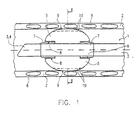
- FIG. 1 shows a first embodiment of a tracheal tube 1 according to the invention or a tracheal ventilation device, which is placed in a trachea 2 is.
- a hollow ventilation cannula 3 ends at its caudal end 4 at an oblique angle their longitudinal axis. At the caudal end 4, ventilation air enters the lungs and out.
- the ventilation cannula 3 leads in a manner not shown over the larynx and the throat out of the patient's mouth and is there with suitable Respirators (not shown) connected.
- a cuff bladder 5 is attached to the ventilation cannula 3 near the caudal end 4.
- the ventilation cannula extends through the cuff bladder.
- the tube 1 is inserted into the trachea 2 such that the cuff 5 in the middle Trachea comes to rest.
- the trachea are suggestively ring-shaped Tracheal clips 6 shown.
- the cuff bladder 5 is approximately balloon-shaped and surrounds the ventilation cannula 3 approximately tubular. It is at two spaced ends 7 attached to the ventilation cannula 3, e.g. by bandaging, shrinking, Welding or gluing, so that the fixed end 7 of the bladder 5 is fluid-tight on the Cannula 3 rests.
- the cannula 3 is connected to a fluid via a connection (not shown in FIG. 1) desired pressure can be filled.
- a fold 8 is provided on the bladder, which extends in a ring around the ventilation cannula 3. With the help of the envelope fold 8 are sufficient axial movements of the cuff bladder 5 and the ventilation cannula 3 relative to each other possible without the contact surface of the cuff bladder 5 medically adversely affected on the trachea 2.
- the cuff bladder 5 is shown placed in the trachea when filled.
- the filling pressure is approximately 20 to 30 mbar (preferably 25 mbar).
- the residual cuff coat folds into folds which are directed predominantly radially inward 10.
- the material of the cuff bladder 5 consists of a flexible soft foil material, preferably with a wall thickness of less than 0.02mm, optimally however 0.01 to 0.005 mm.
- the film material is compatible with the body and exists eg. Made of polyethylene terephthalate (PETP), low-density polyethylene (LDPE), polyvinyl chloride (PVC) or polyurethane (PU).
- the film is not or only minimally stretched, but flexibly curved. It lies with folds 10 of the trachea 2 on.
- the fold areas are indicated by dashed lines.
- the folds are 10 typically arranged axially to the trachea 2 and the ventilation cannula 3 mostly along, parallel to the tube shaft 3
- the wall thickness of the Film is preferably thinner in the area of the formation of the folds 10 than in the wrinkle-free area Area of the contact surface 9.
- the selected filling pressure of the cuff bladder can be between 10 and 30 mbar lie.
- FIG. 2 shows a cross-sectional view along the section line II-II in FIG. 1, with respect to parts of the same reference numerals, reference is made to the description of FIG. 1 becomes.
- Figure 2 it can be seen how the cuff bladder is filled 5, protruding approximately radially inwards, form the folds 10. The folding results from the diameter of the cuff bladder 5, which is larger than in the freely unfolded state the cross section of the trachea 2 to be filled in.
- Each of the folds 10 has at its end, the fold base 11, a fold eyelet 12, which is characterized by the envelope of the cuff in this area.
- FIGS. 3 and 4 depict the enlarged representations of the folds 10.
- Regarding the same reference numerals can be referred to the existing description of the figures.
- each fold 10 consists of two opposing ones in parallel Folded walls 13 which are in physical contact with one another or by one thin secretion film are separated.
- the secretion film forms a certain adhesive layer between the two fold walls 13.
- the fold bridge is typical aligned radially inward from the contact surface 9 of the bladder.
- cuff bubbles of conventional wall thickness forms a fold eyelet 12 on the base of the fold, which forms liquid-guiding capillaries, forms with the application of the thinnest foils for cuff bladder construction a fold envelope 12 made of so small in diameter is that the free flow of the secretion at the base of the fold is inhibited or completely prevented becomes.
- the diameter of the fold eyelet is preferably less than 0.1 or 0.05 mm.
- the fold walls 13 lying opposite one another in the case of a fold 10 Area of the fold base directly by welding or gluing together connected.
- the eyelet 12 is the cause of a possible leak avoided by secretions.
- the fold section adjoining this connection area 16 17 is formed from opposing fold walls 13. This are not connected and form the variable fold section, the fold depth 15 adjusts to the respective tracheal diameter.
- the fold eyelet 12 can be formed in a capillary size at which the actual Flow rate of the secretion is lower than that through the free cross section the fold eyelet is theoretically possible without adhesion and viscosities Flow rate.
- the inhibitory effect of the adhesion and viscosity forces can be so pronounced with the appropriate size of the fold eyelet that the Fold eyelet 12 filled with secretions, but the flow of secretions is not possible is.
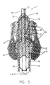
- FIG 5 is a second embodiment of an Enclotrachealtube 1 with the topographical Relationships to the relevant adjacent anatomical structures (Larynx and upper trachea).
- the tracheal tube passes from cranial 18 after caudal 19 the epiglottis (epiglottis) 20, the vocal folds (glottis) 21, and the adjoining the vocal folds so-called subglottic space 22, which is limited by the upper edge of the cuff 23.
- the mechanical anchoring of the tracheal tube occurs below the cricoid cartilage 6, but preferably in the area of the middle trachea by an air-blocked cuff 23.
- the cuff is located within a tampon bladder 24, the tampon bladder and cuff have separate lumens that are independent of each other can be filled.
- the cuff 23 and tampon bladder 24 lie close together when filled.
- the tampon remote bladder 24 extends to the subglottic space 22, up to glottis level 21 or slightly further up to the supraglottic Area 25.
- the cuff 23 does not necessarily have to be arranged inside the tampon bladder 24 his. It can also be in sequential order (cranially) on the tube be arranged, but advantageously in the filled state in the immediate, should be denser so that there is no space between the bubbles Can form a reservoir for germs. For this purpose the bubbles can be shared Contact area permanently connected.
- the two bubbles in the common support surface 26 in one variable distal section (e.g. distal third or distal half) with each other be glued or welded.
- a gluing or welding of the distal common bearing surface 26 is intended to prevent the thin-walled tampon bladder herniated caudally, or their debris in the event of a rupture of the tampon bladder turn caudally and at the caudal end 4 of the ventilation cannula Form the valve-like mechanism.
- the tampon bladder 24 is filled with a suitable liquid or gaseous fluid.
- FIG. 6 shows a third embodiment of a tracheal tube according to the invention displayed.
- the tracheal tube 1 is shown in the filled, freely unfolded state.
- the tampon bladder in the third embodiment 24 in the area of the later vocal fold placement with a preformed Incision 27 provided, which corresponds approximately to the anatomical structure of the glottis 21.
- the incision 27 is preferably not or only in the selected prints little stretch so that the glottis is not subjected to excessive pressure.
- a first channel 28 extends over a plurality of outlet openings 29 is connected to the tampon bladder 24.
- the channel 28 is in the Shaft of the tube integrated and extracorporeal with a scaled reservoir, with liquid Filling media, for example a water column 30, connected.
- the reservoir can however also be used as an expandable compensation balloon 31 (for liquid or gaseous Media).
- the volume of the equalization balloon should be at least correspond to the common volume of the tampon bladder and cuff.
- the material of the balancing balloon 31 is preferably easier to stretch than the material the tampon bladder 24. Pressure increases within the tampon bladder lead in this way preferably for an expansion of the compensation balloon, an expansion of the structures the larynx can be largely avoided.
- the outlet openings 29 are selected in size and number such that a rapid Volume shift between compensation balloon 31 and tampon bladder 24 possible is.
- the cuff 23 is via a second channel integrated in the tube shaft 32 connected to a filling balloon 33.
- the inflation balloon can be made according to the Lanz principle with a self-regulating valve mechanism or a simple one valve-carrying resrvoir bladder.
- FIGS. 7 and 8 show a special embodiment of the compensation balloon 31 shown.
- the compensation balloon 31 is not filled, so that a pattern 34 printed on its wall assumes an irregular deformation.
- the balloon is expanded so that the printed pattern 34 in a straight regular shape appears, which shows the optimal filling pressure the tampon bladder 24 displays.
- a corresponding change in shape of the compensating balloon could take place itself, from the unfilled to the filled state, to the correct one Filling pressure within the tampon bladder are closed.
- a compact, nested arrangement of the two is also conceivable Reservoir bladders for the supply of cuff and tampon bladder in one Version. While the inner bladder pressurized with higher filling pressure supplies the fixation cuff, the outer reservoir bladder holds the tampon bladder unfolded with moderate filling pressure.
- FIG. 9 shows the fourth embodiment of a tracheal ventilation device according to the invention a tracheostomy tube 35 is shown. It will not be natural Airways introduced, but via a so-called stoma 36, which is surgically the front side of the neck.
- the ventilation cannula 3 runs through the stoma 36 and kinks after entering the trachea 2 approximately at right angles to the caudal.
- the cuff bladder 5 is analog formed as in Figures 1 to 4, so that with respect to the same reference numerals reference is made to the previous explanations.
- the analog is Equalization balloon 31 with the channel 28 designed as described in relation to FIG. 6, so that reference is made to these statements in this regard.
- FIG. 10 shows a fifth embodiment of a tracheal ventilation device shown, which can be used as a tracheal tube 1 or as a tracheal cannula 35.
- This Embodiment corresponds to the embodiment shown in Figure 5. Same Parts are provided with the same reference numerals, so that in this regard the explanations refer to Figure 5.
- the tampon bladder is in the fifth embodiment in FIG 24 shorter and does not reach into the area of the glottis. In its expansion it corresponds approximately to the fixing cuff 23 For reasons of clarity, the two separate filling channels 28 and 29 are not located.
- the outer tampon bladder After inserting the cannula, the outer tampon bladder is primarily used as a seal filled. If additional mechanical stabilization of the tracheostomy tube is required, the inner fixing cuff is also unfolded. By contribution a separating agent between the cuff bubbles is the mutual mechanical Influencing the cuff 23 and tampon bladder 24 prevented. To ensure that the tracheal cannula is sealed, the tampon bladder is deployed via a communicating, extracorporeally attached reservoir maintain a mild filling pressure of preferably 10 to 15 mbar.
- FIG. 11 shows a section of a sixth embodiment of an inventive one Tracheal ventilation device shown. This embodiment is from developed the fifth embodiment according to Figure 10. The same parts are the same Provide reference numerals so that reference is made to the explanations relating to FIG can be.
- the fixating cuff 23 and the tampon bladder 24 are strictly sequential arranged one behind the other on the ventilation cannula 3.
- the bearing surface 26 of the cuff 23 and the tampon bladder 24 lie on its walls directly to each other so that no pathogen reservoir can form.
- the walls in the area of the support surface 26 can be connected to one another be glued or welded.
- the tracheal tube is inserted over the cricoid cartilage of the larynx during intubation advanced to the area of the upper tracheal braces so that the cuff bladder 5 comes to rest safely in the tracheal area.
- the shape of the cuff bladder is larger than when it is filled placed in the trachea. Placed in the trachea lies the cuff bladder 5 with a drape the contact surface 9 of the wall of the trachea.
- the cuff bladder 5 is designed such that there is a fold eyelet at the dead end of a fold 10 Forms 12 of such a small diameter that the flow of secretion is inhibited or comes to a complete standstill. This is preferably done by the viscosity of the Secretions or by the adhesive forces acting on the secretion within the capillary eye. The aspiration of secretions can be prevented and the emergence of a ventilation-associated pneumonia can be prevented.
- the small diameter of the eyelets 12 can be achieved by using certain achieved only a few micrometers thick, flexible foils in the cuff bubble design become.
- Variable areas of the opposing fold walls 13 can also be used e.g. be connected to each other by gluing or welding. Ideally such a connection of the fold walls 13 takes place in the area of the fold eyelet 12, so that every flow of secretion is prevented.
- the tracheal ventilation device can also be used as a gastric tube be used.
- the gastric tube is inserted into the esophagus instead of the trachea inserted, with a corresponding marking on the probe shaft is provided for positioning the probe.
- the esophagus Cuff bladder can be unfolded just as freely, with drapery on the wall of the The esophagus is tension-free and there are fold eyelets at the dead end of the resulting folds with such a small diameter that the free flow counteract secretions through the eyelets. This allows a gentle tamponing of the transmural tissue pressure Reach esophagus.
- the tissue of the esophagus is not under tension taken.
- the currently released lumen of the esophagus is being preserved the oesophageal fold is simply tamped.
- the gastric tube seals on long-term contracts Way against rising gastrointestinal secretion.
- gastric tubes and tracheal ventilation devices have always been separate Devices were constructed and not mutually for the other use were interchangeable. is both an application with the device according to the invention possible as a tracheal ventilation device or as a gastric tube.
- the Respiratory cannula is used in the case of the gastric tube as an inner channel-like lumen, through which an actual feeding tube can be carried out or through which the food supply itself takes place.
- the gastric tube can also be used in the sense of a so-called Senstaken Blakemore tube be used.
- the cuff bladder is also in the esophagus placed. This makes it possible to improve the blood supply to the surrounding vessels of the esophagus by varying the filling pressure of the cuff bladder. For example bleeding from surrounding mucosal vessels can be stopped. Training the specific, previously described unfolding of the residual Cuff jacket, it also allows the cuff filling to the necessary vascular closure pressure to adapt exactly without the cuff and adjoining To take structures under significant tension. Vascular hemorrhage can also occur with minimum necessary pressure can be prevented. The mucous membrane of the esophagus becomes like this as traumatized as possible. When used as a Sengstake, the interior serves channel-like lumens as a probe shaft. The gastric end of the tube can be open or closed.
Abstract
Description
Die Erfindung betrifft eine Trachealbeatmungsvorrichtung, insbesondere Trachealtubus oder Trachealkanüle, die die Trachea zum Beatmen eines Patienten möglichst dicht verschließt, mit einer die Trachea unterhalb der Glottis blockierenden Cuffblase, durch die eine Beatmungskanüle hindurchgeführt ist, wobei die Cuffblase in gefülltem, ohne Begrenzung frei auffaltbarem Zustand größer ist als in gefülltem Zustand in der Trachea platziert, und aus flexiblem Weichfolienmaterial besteht, . wobei die Cuffblase mit Faltenwurf an der Trachea anlegbar ist.The invention relates to a tracheal ventilation device, in particular Tracheal tube or tracheal cannula that connects the trachea to a patient's ventilation closed as tightly as possible, with one blocking the trachea below the glottis Cuff bladder through which a ventilation cannula is passed, the cuff bladder in the filled, freely unfoldable state is larger than in the filled Condition placed in the trachea, and consists of flexible soft film material, , the cuff bladder can be applied to the trachea by drapery.
Eine in der US-A-3,766,927 vorgeschlagene Trachealbeatmungsvorrichtung dieser Gattung hat eine Cuffblase, welche größer ist als die Trachea und sich von Innen unterDruck an die Trachea anlegt. Das Folienmaterial der Cuffblase'hat eine Dicke von 0,0254 mm, wobei alternativ auch eine Dicke von 0,0762 mm vorgeschlagen wird. Beim Einatmen entsteht in der Lunge ein Gegendruck gegen die Cuffblase, wobei sich die Cuffblase zur Rachenseite gerichtet etwa tropfenförmig ausformt, so dass sie gegen die Wand der Trachea gepresst eine bessere Dichtung gewährleistet Bei langzeitintubierten Patienten besteht mit dieser Cuffblase jedoch die Gefahr, dass Sekret über die Cuffblase hinweg zur Lunge gelangt.A tracheal ventilator proposed in US-A-3,766,927 Genus has a cuff bladder, which is larger than the trachea and from the inside applying pressure to the trachea. The foil material of the cuff bladder has a thickness of 0.0254 mm, alternatively a thickness of 0.0762 mm is also proposed becomes. When inhaled, there is a counterpressure in the lungs against the cuff bladder, whereby the cuff bladder is shaped like a drop directed towards the throat, so that they pressed a better seal against the wall of the trachea Guaranteed in long-term incubated patients with this cuff bladder the risk of secretions reaching the lungs via the cuff bladder.
Die US-A-3 610 247 offenbart eine Trachealbeatmungsvorrichtung, welche von der Struktur her der in der US-A-3,766,927 offenbarten Vorrichtung entspricht. Sie hat eine Cuffblase aus vorzugsweise semipermeablem Material, welches an seiner Außenseite ein Anästhetikum an die Wand der Trachea abgeben kann. Als Wanddicken der Folie sind Beispiele von 0,05, 0,07 und 0,1 mm angegeben, wobei theoretisch auch Folien dünner als 0,05 mm verwendbar sind. Bezüglich der Dichtung zeigt diese Vorrichtung ein Verhalten ähnlich der US-A-3,766,927. US-A-3 610 247 discloses a tracheal ventilator, which is of the Structure corresponds to the device disclosed in US-A-3,766,927. she has a cuff bladder made of preferably semi-permeable material, which at its Can deliver an anesthetic to the wall of the trachea. As Wall thicknesses of the film are given as examples of 0.05, 0.07 and 0.1 mm theoretically, films thinner than 0.05 mm can also be used. Regarding the Seal shows this device a behavior similar to US-A-3,766,927.
Bei einem aus der DE 196 38 935 bekannten Trachealtubus wird vorgeschlagen, für die Cuffblase ein folienartiges, äußerst dehnbares Material zu verwenden, das sich eng an die Trachea bzw. an die Binnenstrukturen des subglottischen Kehlkopfes (Larynx) anschmiegt Um die Tamponade des subglottischen Raumes zu optimieren, wird empfohlen, die Cuffblase der Morphologie des auszufüllenden Raumes entsprechend zu präformieren. Damit soll unerwünschter Faltenwurf vermieden werden. Dies soll gewährleisten, daß die Folie eng an der Trachea anliegt, so daß möglichst kein Sekret aus dem Rachenraum in die Lunge gelangt Mikroaspiration von Sekret über die Cuffblase hinweg wird damit erheblich reduziert.In a tracheal tube known from DE 196 38 935 proposed using a film-like, extremely stretchable material for the cuff bladder, that closely relates to the trachea or to the internal structures of the subglottic Larynx nestles around the tamponade of the subglottic To optimize the space, it is recommended that the cuff bubble of the morphology of the to be preformed accordingly. This is said to be undesirable Wrinkles are avoided. This is to ensure that the film is close to the trachea is applied so that as little secretions as possible from the throat into the lungs If micro-aspiration of secretions passes over the cuff bladder, this becomes significant reduced.
Sekret, das in das distale tracheabronchiale System gelangt, ist für die Entstehung des überwiegenden Teils aller beatmungsassoziierter Pneumonien (Lungenentzündungen verantwortlich.Secretion that gets into the distal tracheabronchial system is responsible for the emergence the majority of all ventilation-associated pneumonia (pneumonia responsible.
Bei dem in der DE 196 38 935 vorgeschlagenen Trachealtubus dehnt sich die Cuffblase beim Aufblasen elastisch auf und legt sich ohne Faltenwurf eng an die Wand der Trachea an. Übersteigt der Fülldruck der Cuffblase den Durchblutungsdruck des Scheimhaut versorgenden Gefäßbettes, so können schwerwiegende strukturelle Läsionen des Epithels die Folge sein. Vor allem bei langzeitintubierten Patienten sollte der Fülldruck in der Cuffblase auf einem möglichst niedrigen, die Schleimhautperfusion nicht beeinträchtigenden Niveau gehalten werden. Wird der Fülldruck hingegen zu niedrig gewählt, kann dies zur Leckage bakteriell besiedelten Rachensekrets über die Cuffblase hinweg und damit zur Besiedelung und infektion des Lungengewebes führen.In the tracheal tube proposed in DE 196 38 935, the cuff bladder expands when inflated it is elastic and lies close to the wall without folds the trachea. If the filling pressure of the cuff bladder exceeds the blood pressure of the Mucous membrane supplying the vascular bed, so serious structural Lesions of the epithelium may result. Especially in long-term incubated patients should the filling pressure in the cuff bladder at the lowest possible, the mucosal perfusion non-impairing level. However, the filling pressure chosen too low, this can lead to leakage of bacterially populated pharynx the cuff bladder and thus for colonization and infection of the lung tissue to lead.
Für die Langzeitintubation wurde daher vorgeschlagen, Cuffblasen zu verwenden, die sich bei mäßigem Fülldruck in der Trachea entfalten, ohne daß dabei der Cuffmantel selbst aufgedeht werden muß. Der Durchmesser der frei entfalteten Cuffblase ist dabei größer als der der zu verschließenden Trachea. Der residuale Anteil des Cuffmantels stülpt sich bei der trachealen Blockung der Cuffmanschette in Falten. Andererseits hat sich aber herausgestellt, daß derartige Cuff-Manschetten eine hohe Durchlässigkeit für Rachensekret aufweisen, was eine erhöhte Pneumoniegefahr bedeutet Die Sekretleckage dieser Cuffblasen liegt im Bereich von Millilitern pro Sekunde und entspricht damit quantitativ sogar einer Makroaspiration.For long-term intubation, it has therefore been proposed to use cuff bladders that unfold in the trachea at moderate inflation pressure, without the cuff coat must be blown up. The diameter of the freely unfolded cuff bladder is included larger than that of the trachea to be occluded. The residual portion of the cuff jacket folds when the cuff is blocked tracheally. on the other hand but it has been found that such cuff cuffs have a high Have permeability to pharynx secretion, which means an increased risk of pneumonia The secretion leakage of these cuff bubbles is in the range of milliliters per Second and thus corresponds quantitatively to macro aspiration.
Es ist daher davon auszugehen, daß konventionelle Cuffblasen für den Großteil der
bei langzeitbeatmeten Patienten häufigen Pneumonien (Inzidenz 10% bis 80%, abhängig
vom jeweiligen Patientengut) verantwortlich ist. It can therefore be assumed that conventional cuff bubbles for the majority of the
frequent pneumonia in long-term ventilated patients (
Der Erfindung liegt die Aufgabe zugrunde, eine Trachealbeatmungsvorrichtung der eingangs genannten Gattung dahingehend zu verbessern, dass ein Patient damit möglichst schonend bei niedrigen Drücken über lange Zeit intubiert werden kann, wobei das Infektionsrisiko gering sein soll.The invention has for its object a tracheal ventilation device to improve the genre mentioned in such a way that a patient with it can be intubated for as long as possible at low pressures, the risk of infection should be low.
Diese Aufgabe wird erfindungsgemäß gelöst mit einer gattungsgemäßen Trachealbeatmungsvorrichtung, welche dadurch gekennzeichnet ist, dass die Wanddicke der Folie weniger als oder gleich 0,02 mm beträgt und die Cuffblase derart ausgebildet ist, dass die am toten Ende einer Falte entstehende Faltenöse einen geringen Durchmesser aufweist, der dem freien Durchfluss des Sekrets durch die Faltenöse hemmend entgegenwirkt.This object is achieved according to the invention with a generic Tracheal ventilation device, which is characterized in that the Wall thickness of the film is less than or equal to 0.02 mm and the cuff bubble is designed such that the fold eyelet that arises at the dead end of a fold has a small diameter that allows the free flow of the secretion through counteracts the wrinkle eyelet.
Erstaunlicherweise lässt sich der Sekretfluss durch die spezifische Ausbildung der Cuff-Faltung im Bereich einer Faltenöse, also am Faltengrund, beeinflussen. Während im Stand der Technik bisher davon ausgegangen wurde, dass Cuffblasen mit Faltenwurf wegen des geringen Fülldruckes nicht ausreichend dicht an der Trachea anliegen können, gibt die Erfindung einen Weg zur Hemmung des Sekretflusses im Bereich einer Faltenöse. Beim Blocken der Cuff-Manschette bilden sich am tiefen Ende der Falte, am Faltengrund, Faltenösen aus, welche einen derart geringen Durchmesser haben, dass der Sektretfluss gebremst wird oder im Idealfall zum Stillstand kommt. Dies kann bereits bei Foliendicken ab oder unter 0,002 mm eintreten.Surprisingly, the flow of secretions can be controlled by the specific training of Influence cuff folding in the area of a fold eyelet, i.e. on the fold base. While it was previously assumed in the prior art that cuff bubbles with drapery because of the low filling pressure not sufficiently close to the Trachea may be present, the invention provides a way to inhibit the Secretion flow in the area of a fold eyelet. Form when blocking the cuff at the deep end of the fold, at the base of the fold, fold eyelets, which one such have a small diameter that the flow of secretion is slowed down or ideally comes to a standstill. This can already be the case with film thicknesses from or below 0.002 mm enter.
Die Steuerung der Dichtheit über Faltenösen am Faltengrund ist überraschend, da die Leckage bisher stets als Problem des Drucks aufgefasst wurde. Eine konstruktive Änderung des Faltenwurfes war bisher noch nie in Betracht gezogen worden. The control of the tightness via eyelets on the bottom of the fold is surprising because the leakage has always been viewed as a problem of pressure. A constructive changes to the drapery have never been considered Service.
Vorzugsweise ist die Faltenöse in Kapillargröße ausgebildet. Es resultieren dann ausreichende Adhäsionskräfte des Sekretes an der Faltenöse bzw. ein ausreichender viskositätsabhängiger Widerstand des Sekretes, um den Sekretfluß zu reduzieren. Die Strömungsgeschwindigkeit in der kapillargroßen Faltenöse ist dann geringer als die theoretisch mögliche Geschwindigkeit ohne Adhäsions- bzw. Viskositiätskräfte, so daß über die Zeit weniger Sekret hindurchfließt. Im Optimalfall kann der Durchmesser der Öse so klein gestaltet sein, daß der Sekretfluß ganz zum Erliegen kommt.The eyelet is preferably formed in a capillary size. Adequate results then result Adhesive forces of the secretion on the fold eyelet or a sufficient viscosity-dependent resistance of the secretion to reduce the flow of secretion. The flow velocity in the capillary-sized fold eyelet is then less than the theoretically possible speed without adhesion or viscosity forces, so that less secretion flows through over time. Ideally, the diameter the eyelet should be designed so small that the flow of secretion comes to a complete standstill.
Besonders vorteilhaft kann der Durchmesser der Faltenöse weniger als 0,11 oder 0,05 mm betragen. Unter 0, 1 mm setzt bereits eine gewisse Hemmung der Fließgeschwindigkeit des Sekrets durch die Öse ein. Bei einem Faltenösendurchmesser von unter 0,05 mm verlangsamt sich der Sekretfluß weiter und kommt annähernd zum Erliegen.The diameter of the fold eyelet can be particularly advantageously less than 0.11 or 0.05 mm. Below 0.1 mm there is already a certain inhibition of the Secretion flow rate through the eyelet. With a wrinkle eye diameter of less than 0.05 mm the secretion flow slows down and comes close to to a halt.
Günstigerweise kann die Wandstärke des Folienmaterials derart dünn gewählt sein, daß sich der Innenradius der sich bildenden Faltenösen bei physiologisch verträglichen Fülldrucken soweit reduziert, daß Sekret an einem freien Durchfluß gehindert wird. Je flexibler und dünner das Material, desto geringer ist der Durchmesser der Öse. The wall thickness of the film material can advantageously be chosen to be so thin that that the inner radius of the fold eyelets that form is physiologically acceptable Filling pressure reduced to such an extent that secretions are prevented from flowing freely becomes. The more flexible and thinner the material, the smaller the diameter of the Eyelet.
Die Wandstärken konventioneller Cuffblasen liegen überwiegend im Bereich von 0,06 bis 0,1 mm.The wall thicknesses of conventional cuff bubbles are mostly in the range of 0.06 up to 0.1 mm.
Als Variante der Erfindung beträgt die Wanddicke der Folie etwa 0,01 bis 0,005 mm. Im Bereich einer Wandstärke von 0,01 bis 0,005 mm kann mit einer weichen, flexiblen Folie bereits eine befriedigende Hemmung des Sekretflusses bzw. seine Stase im Bereich des Faltengrundes erreicht werden.As a variant of the invention, the wall thickness of the film is approximately 0.01 to 0.005 mm. In the range of a wall thickness of 0.01 to 0.005 mm you can use a soft, flexible Already a satisfactory inhibition of the secretion flow or its stasis in the Area of the fold base can be reached.
Gemäß einer bevorzugten Ausführungsform kann das Folienmaterial dar Cuffblase zum Beispiel aus Polyethlenteraphtalat (PETP), niedrig dichtem Polyethylen (LDPE), Polyvinylchlorid (PCV) oder Polyurethan (PU) bestehen. Diese Materialien sind körperverträglich und eignen sich in entsprechend dünnwandiger Verarbeitung besonders gut zur Ausbildung eines dicht schließenden Faltenwurfes. Copolymerbeimischungen zur Modifikation der Materialeigenschaften sind denkbar (z.B. LDPE-EVA).According to a preferred embodiment, the film material can be the cuff bladder for example made of polyethylene terephthalate (PETP), low-density polyethylene (LDPE), Polyvinyl chloride (PCV) or polyurethane (PU) exist. These materials are compatible with the body and are particularly suitable in thin-walled processing good for forming a tightly fitting drapery. Copolymerbeimischungen to modify the material properties are conceivable (e.g. LDPE-EVA).
Möglicherweise besteht die Cuffblase aus einem sich selbst anhaftenden Material, dessen Adhäsion zur Reduktion des lichten Durchmessers einer Öse am Faltengrund beiträgt.The cuff bladder may be made of a self-adhesive material its adhesion to reduce the clear diameter of an eyelet on the base of the folds contributes.
Als Variante der Erfindung kann die Wanddicke der Folie im Bereich des Faltenwurfes dünner sein, als in dem, der Trachealschleimhaut unmittelbar anliegenden, faltenfreien Bereich. lm dünnwandigeren Cuffbereich bilden sich bevorzugt Falten aus, da die Folie hier leichter verformbar ist. Der Faltengrund kann aufgrund der geringeren Wandstärke Ösen kleineren Durchmessers ausbilden. Im dickwandigeren Cuffbereich zwischen den Falten verhält sich der Cuffmantel etwas starrer, so daß er nur gerundet an der Wand der Trachea anliegt.As a variant of the invention, the wall thickness of the film can be in the area of the folds be thinner than in the wrinkle-free area immediately adjacent to the tracheal mucosa Area. Wrinkles preferably form in the thin-walled cuff area, because the film is easier to deform here. The fold base can be due to the lesser Form wall thickness of eyelets of smaller diameter. In the thick-walled cuff area the cuff coat behaves somewhat more rigidly between the folds, so that it is only rounded lies against the wall of the trachea.
In besonderer Weise können sich die in eine Falte gegenüberliegenden Faltenwände im Bereich nahe des Faltengrundes miteinander verbunden sein. Die Verbindungsstelle kann unmittelbar benachbart zu der sich bildenden Faltenöse vorgesehen sein, so daß durch sie die Größe der Faltenöse auf einen gewünschten Durchmesser einzustellen ist.In a special way, the fold walls lying opposite one another can be connected to each other in the area near the base of the folds. The liaison office can be provided immediately adjacent to the forming eyelet be so that through them the size of the fold eyelet to a desired Diameter is to be set.
Vorzugsweise können die sich gegenüberliegenden Faltenwände am toten Ende der Falte, die Faltenöse ausfüllend, miteinander verbunden sein und so den Sekretfluß sicher unterbinden.Preferably, the opposite fold walls at the dead end of the Fold, filling the eyelet, be connected to each other and thus the flow of secretion is safe prevention.
Denkbar können die sich gegenüberilegenden Faltenwände einer Falte miteinander verschweißt oder verklebt sein.The opposing fold walls of a fold with one another are conceivable be welded or glued.
In besonderer Weise kann sich in der Falte, an den Verbindungsbereich der sich gegenüberliegenden Faltenwäinde angrenzend, ein im Querschnitt in der Faltentiefe variabler Faltenabschnitt anschließen, in dem die sich gegenüberliegenden Faltenwände nicht stofflich miteinander verbunden sind. Über einen derartigen präformierten Faltenwurf mit variabler Faltentiefe kann sich die Cuffblase der Trachea, dem Konzept residualen Cuffmantels, in Größe und Form anpassen.In a special way can be in the fold, at the connection area of the opposite pleats, one in cross-section in the pleat depth Connect variable fold section in which the opposite fold walls are not physically connected. About such a preformed The cuff bladder of the trachea, the concept, can fold with a variable depth of fold Adjust residual cuff coat, in size and shape.
Bei einem aus DE 196 38 935 bekannten Trachealtubus dieser Gattung wird vorgeschlagen, die konventionelle Cuffmanschette des Trachealtubus durch eine zweite, sich unmittelbar an die Cuffmanschette nach oral anschließende, und den sog. subglottischen Raum (Raum zwischen Cuffmanschettenoberrand und den Stimmlippen) vollständig ausfüllende Tamponierblase zu ergänzen. Diese besteht aus einem folienartigen, äußerst dehnbaren Material, das sich unter Aufdehnung eng an die Binnenstrukturen des subglottischen Raumes anschmiegt. Um die Tamponade des subglottischen Raumes zu optimieren, wird empfohlen die Blase der Morphologie des auszufüllenden Raumes entsprechend zu präformieren. Durch eine möglichst glatte. faltenfreie Oberfläche der Tamponierblase soll jede Ansammlung von Sekreten bzw. die Ausbildung eines subglottischen Erregerreservoirs verhindert werden.In a tracheal tube of this type known from DE 196 38 935, it is proposed that the conventional cuff of the tracheal tube with a second, directly adjoining the cuff after orally, and the so-called subglottic Space (space between the upper cuff and the vocal folds) to completely fill the tampon bladder. This consists of a film-like, extremely stretchy material that is stretched closely to the internal structures hugs the subglottic space. To the tamponade of the subglottic To optimize space, it is recommended the bubble of the morphology of the to be preformed accordingly. By as smooth as possible. wrinkle-free surface of the tampon bladder should any accumulation of secretions or the formation of a subglottic pathogen reservoir can be prevented.
Das Aufdehnen eines derartigen Verdrängungskörpers geht jedoch vor allem im Bereich des morphologisch aufwendig gestalteten inneren Larynx (Kehlkopfes) mit der Entstehung von Druckspitzen im Bereich prominenter, in den Binnenraum hineinreichender Strukturen einher.However, the expansion of such a displacement body is primarily in the area of the morphologically complex inner larynx (larynx) with the Creation of pressure peaks in the area of prominent, reaching into the interior Structures.
Übersteigt der Fülldruck der Tamponierblase den Perfusionsdruck des schleimhautversorgenden Gefäßbettes, können vorallem im Bereich des dorsolateralen subglottischen Kehlkopfes schwerwiegende Läsionen der Wandstrukturen die Folge sein.If the filling pressure of the tampon bladder exceeds the perfusion pressure of the person supplying the mucous membrane Vascular bed, especially in the dorsolateral subglottic area Larynx can cause serious lesions in the wall structures.
Um einer Druckschädigung des Kehlkopfes vorzubeugen, wird empfohlen die Tamponlerblase ebenfalls residualvolumig zu gestalten, d.h. ihr Volumen bei freier Entfaltung soll das Volumen des auszufüllenden inneren Kehlkopfes überschreiten. Die Tamponierblase entspricht dabei den erfindungsgemäßen Prinzipien zur dichtenden und schonenden Cuffblasengestaltung. Der Ausbildung der beschriebenen kapillarartigen Strukturen wird so vorgebeugt.In order to prevent pressure damage to the larynx, the tamponler bladder is recommended also to be designed with residual volume, i.e. their volume with free development should exceed the volume of the inner larynx to be filled. The Tampon bladder corresponds to the sealing principles according to the invention and gentle cuff bladder design. The formation of the described capillary This prevents structures.
Da bei vielen Anwendungen eine zuverlässige, mechanisch belastbare Verankerung des Trachealtubus in der Luftröhre gefordert wird, darf abhängig von der jeweiligen Materialqualität eine gewisse Mindestwandstärke der fixierenden Cuffmanschette nicht unterschritten werden. Der Ausbildung flüssigkeitsdrainierender Faltenösen kann so, trotz weitgehender Reduzierung der Wandstärke, nicht in allen Fällen ausreichend vorgebeugt werden.Because in many applications a reliable, mechanically resilient anchorage of the tracheal tube in the trachea may depend on the particular Material quality a certain minimum wall thickness of the fixing cuff not be undercut. The formation of fluid-draining eyelets can thus, despite the substantial reduction in wall thickness, not sufficient in all cases be prevented.
Um dennoch ein optimales Dichtungsverhalten zu gewährleisten, schlägt die Erfindung die Ergänzung der mechanisch fixierenden Cuffmanschette durch eine zusätzliche dichtende, den zuvor beschriebenen Gestaltungsprinzipien zur Dichtung und Gewebeverträglichkeit entsprechende, Tamponierblase vor. Die Tamponierblase kann mit einem minimalen Fülldruck von vorzugsweise 10 bis 15 mbar beaufschlagt sein, welcher lediglich das Entfalten der dünnen, dichtenden Blasenwandung zur Aufgabe hat.In order to nevertheless ensure an optimal sealing behavior, the invention proposes the addition of an additional mechanical cuff to the cuff sealing, the previously described design principles for sealing and Tissue bladder corresponding to tissue compatibility. The tampon bladder can be pressurized with a minimum filling pressure of preferably 10 to 15 mbar, which is only the task of unfolding the thin, sealing bladder wall Has.
Die Tamponierblase kann hinsichtlich Anordnung und Bezug zum Tubusschaft bzw. zur fixierender Cuffmanschette den in DE 196 38 935 beschriebenen Ausführungsformen entsprechen.The tampon bladder can be arranged and related to the tube shaft or for fixing cuff the embodiments described in DE 196 38 935 correspond.
Es wird vorgeschlagen, daß die fixierende Cuffmanschette an der kaudalen Seite der Vorrichtung, und die Tamponierblase relativ dazu kranial angebracht ist. Die Fixier-Cuffmanschette wird bei der Intubation über den Ringknorpel des Kehlkopfes hinweg, bis vorzugsweise in den Bereich des mittleren trachealen Drittels vorgeschoben, wo sie sicher und tracheal verträglich verankert wird. Die kranial dazu angeordnete Tamponierblase kann sich in Richtung des subglottischen Raumes ausdehnen und sorgt dort, der fixierenden Cuffmanschette vorgeschaltet, für eine Abdichtung gegen vom Rachen her einsickemdes Sekret.It is proposed that the fixing cuff on the caudal side of the Device, and the tampon bladder is mounted cranially relative thereto. The fixing cuff during intubation via the cricoid cartilage of the larynx away, preferably advanced into the middle tracheal third, where it is anchored safely and tracheally. The cranial one The tampon bladder can expand in the direction of the subglottic space and provides a seal there, upstream of the fixing cuff against secretions seeping in from the throat.
Denkbar können die Fixiercuffmanschette und die Tamponierblase in sequenzieller Anordnung auf der Beatmungskanüle positioniert sein. Die Tamponierblase kann in ihrer Ausdehnung nach kranial den sog. subglottischen Raum teilweise erfassen, bis zur Glottisebene oder geringfügig darüber hinaus reichen. Da beide Blasen über entsprechende, innerhalb des Tubusschaftes angebrachte Versorgungslumina separat befüllt werden, können die Funktionen von Fixier-Cuffmanschette und Tamponierblase bei serieller Anordnung weitgehend unabhängig voneinander kontrolliert werden.The fixation cuff and the tampon bladder can be used sequentially Be positioned on the ventilator cannula arrangement. The tampon bladder can In terms of its extent, the so-called subglottic space is partially covered up to to the glottic level or slightly beyond. Since both bubbles have corresponding Supply lumens attached separately within the tube shaft The functions of the fixing cuff and tampon bladder can be filled controlled largely independently of each other in a serial arrangement become.
Vorzugsweise ist die Verbindungsstelle zwischen den beiden seriell angeordneten Blasen derart ausgestaltet, daß sich in ihrem Bereich, im gefüllten, tracheal entfalteten Zustand, kein Sekret ansammeln kann.The connection point between the two is preferably arranged in series Bubbles designed so that in their area, in the filled, tracheally unfolded Condition, no secretions can accumulate.
Günstigerweise kann die Fixier-Cuffmanschette mindestens bereichsweise, vorzugsweise vollständig, von der Tamponierblase umschlossen sein. Die äußere Tamponierblase kann sich also nach kaudal bis in einen variablen Bereich der Fixier-Cuffmanschette ausdehnen. Die Bildung eines Erregerreservoirs zwischen den Blasen wird so verhindert.The fixing cuff can advantageously, at least in regions, preferably completely enclosed by the tampon bladder. The outer tampon can therefore extend caudally into a variable area of the fixing cuff expand. The formation of a pathogen reservoir between the This prevents bubbles.
In einer bevorzugten Variante ist die den Tubus tracheal fixierende Cuffmanschette von der Tamponierblase völlig umschlossen. Die Tamponierblase reicht vom kaudaten Ende über das kraniale Ende der Cuffmanschette bis in den sog. subglottischen Raum hinein bzw. bis in den Bereich der Stimmlippenebene oder geringfügig darüber hinaus. Bei dieser ineinandergeschachtelten Ausführungsform der Kombination einer fixierenden Cuffmanschette mit einer Tamponierblase schlägt die Erfindung eine besondere Art der Handhabung vor.In a preferred variant, the cuff is tracheally fixing the tube completely enclosed by the tampon bladder. The tampon blister ranges from the chewing data End over the cranial end of the cuff up to the so-called subglottic Space into or up to or slightly above the area of the vocal fold level out. In this nested embodiment, the combination of one fixing cuff with a tampon bladder, the invention proposes a special Type of handling before.
Nach konventioneller Intubation soll initial die äußere flüssigkeitsdicht schließende Tamponierblase befüllt werden und sich der Wandung des auszufüllenden Binnenraums unter minimalem Druck anschmiegen. Anschließend wird dann die im Inneren angeordnete Fixiercuffmanschette zur Stabillsierung des Tubus in der Trachea in gewohnter Weise und mit üblichen Fülldrücken entfaltet. Die Fixiercuffmanschette hat somit keinen Flüssigkeitskontakt, die eventuelle Ausbildung von Faltenösen im Mantel des inneren Cuffs also keinen flüssigkeitsdrainierenden Effekt.After conventional intubation, the outer, fluid-tight closing should initially Tamponing bladder are filled and the wall of the inner space to be filled nestle under minimal pressure. Then the inside Arranged cuff to stabilize the tube in the trachea in the usual way Unfolded and with usual inflation pressures. The fixation cuff has therefore no liquid contact, the possible formation of fold eyelets in the coat the inner cuff has no liquid draining effect.
Um ein gegenseitiges Anhaften der beiden Blasen bei ihrer Entfaltung zu verhindern und ihr unabhängiges mechanisches Verhalten bei der Beatmung zu gewährleisten, wird vorgeschlagen ein geringe Menge eines trennendes Mediums, wie z.B. Öl oder Talkum, in den Raum zwischen den Blasen einzubringen.To prevent the two bubbles from sticking together as they unfold and to ensure their independent mechanical behavior during ventilation, it is proposed to use a small amount of a separating medium, e.g. Oil or Talcum to bring in the space between the bubbles.
Wird die mit minimalem, gewebeschonendem Fülldruck beaufschlagte Tamponierblase bis in den Bereich der Glottis bzw. geringfügig darüber hinaus ausgedehnt, wird der potentielle Eintrittsweg für keimhaltiges Sekret maximal verlängert. Das Sekretvolumen wird durch die verdrängende Tamponierblase auf einen schmalen, den epitheleigenen Abwehrfaktoren exponierten Film reduziert und somit in seiner Fließgeschwindigkeit maximal reduziert. Insgesamt wird die Effizienz der lokalen Abwehrmechanismen dadurch wesentlich optimiert. Is the tampon bladder applied with a minimal, tissue-protecting filling pressure is extended into the area of the glottis or slightly beyond the potential entry path for germ-containing secretions is extended to a maximum. The secretion volume is replaced by the displacing tampon bladder on a narrow, the epithelial defense factors reduced film and thus in its flow rate reduced to the maximum. Overall, the efficiency of local defense mechanisms thereby significantly optimized.
Da die Stase erregerhaltigen Materials oberhalb der tracheal fixierenden Cuffmanschette praktisch vollständig unterbunden wird, kann chronisch entzündlich bedingten Veränderungen der Schleimhaut zudern vorgebeugt werden.Because the stasis contains material containing excitation above the tracheally fixing cuff practically completely prevented, can be chronically inflammatory Changes in the mucous membrane can also be prevented.
Reicht die Tamponierblase über die Stimmlippen hinaus bis in den supraglottischen Bereich, kann der permanente traumatisierende Kontakt des Tubusschaftes mit den Stimmlippen durch die spannungsfreie Umkleidung der Stimmlippen mit dem Mantel der Tamponierblase reduziert werden.The tampon bladder extends beyond the vocal folds into the supraglottic Area, the permanent traumatic contact of the tube shaft with the Vocal cords through the tension-free covering of the vocal cords with the coat the tampon bladder can be reduced.
Auch die Dichtigkeit jedes herkömmlichen Tubus (high-volume/low-pressure, high-pressure/low-volume Cuff oder intermediär gestalteter Cuff), welcher nicht den zuvor beschriebenen Vorzug der Elimination des subglottischen Erregerreservoirs bietet, kann durch die ineinandergeschachtelte Anordnung des fixierten Cuffs und einer nur wenige Mikrometer wandstarken Tamponierblase hinsichtlich Dichtigkeit und Gewebeverträglichkeit optimiert werden. Die äußere Tamponierblase sollt die Fixiermanschette dabei in ihrer kranialen und kaudalen Ausdehnung nur geringfügig überschreiten bzw. in ihren Abmessungen der Fixiermanschette entsprechen. Beide Blasen sind getrennt befüllbar. Auch hier soll durch die initiale Entfaltung der äußeren, wenige Mikrometer dünnen, dicht schließenden Hülle verhindert werden, daß die Ausbildung flüssigkeltsleitender Tubuli der inneren wandstärkeren Cuffmanschette zur Ursache einer Leckage von Sekreten werden kann.The tightness of any conventional tube (high-volume / low-pressure, high-pressure / low-volume Cuff or intermediate cuff), which is not the previous one the described advantage of eliminating the subglottic pathogen reservoir, can by the nested arrangement of the fixed cuff and one only a few micrometers thick wall-mounted tampon bladder with regard to tightness and tissue compatibility be optimized. The outer tampon bladder should the fixation cuff only slightly exceed in its cranial and caudal extent or correspond in their dimensions to the fixing collar. Both bubbles can be filled separately. Here too the initial unfolding of the outer, a few microns of thin, tightly closing shell can be prevented Formation of fluid-conducting tubules of the inner wall-thick cuff for Can cause leakage of secretions.
Eine derartige Anordnung von dichtender und stabilisierender Hülle macht die Anwendung der Erfindung nicht nur auf Trachealtuben, sondern in besonderer Weise auch auf Trachealkanülen denkbar. Trachealkanülen werden nicht über den Kehlkopf, sondern über eine operativ angelegte Öffnung (Stoma) in die Luftöhre eingeführt.Such an arrangement of sealing and stabilizing sleeve makes the application the invention not only on tracheal tubes, but in a special way also conceivable on tracheostomy tubes. Tracheostomy tubes are not placed over the larynx, but inserted into the trachea through an operative opening (stoma).
Die Aufrechterhaltung des Fülldruckes in sämtlichen beschriebenen Cuff- und Tamponierblasen wird durch extrakorporal angebrachte Reservoirs gewährleistet. Diese können, entsprechend dem Lanz'schen Prinzip, mit einem selbstregulierenden Ventilmechanismus ausgestattet, oder in der Art simpler, ventiltragender Reservoirblasen gestaltet sein. The maintenance of the filling pressure in all described cuff and tampon bladders is guaranteed by extracorporeally attached reservoirs. These can, according to the Lanz principle, with a self-regulating valve mechanism equipped, or in the manner of simple, valve-carrying reservoir bubbles be designed.
Zur Abschätzung des gewünschten Fülldrucks kann eine aufgedruckte Figur bzw. eine spezifische Form der Reservoirblase gewählt werden, welche sich bei entsprechendem Füllzustand in spezifischer Weise verändert.To estimate the desired filling pressure, a printed figure or a specific shape of the reservoir bladder can be selected, which changes with the corresponding Fill state changed in a specific way.
Um zu vermeiden daß Druckschwankungen innerhalb der Trachea bzw. des Larynx zu einer Aufdehnung der Wandstrukturen führen, sollte die Materialcompliance der Reservoirblase die der Cuff- bzw. Tamponierblase überschreiten.To avoid pressure fluctuations within the trachea or larynx the material compliance of the Reservoir bladder that exceed the cuff or tampon bladder.
Der zur Tamponierblase führende Versorgungsschenkel soll ausreichend großlumig gewählt werden, um einen raschen Druckausgleich herstellen zu können.The supply leg leading to the tampon bladder should be sufficiently large can be selected in order to be able to quickly equalize the pressure.
Zur Befüllung der dichtenden bzw. fixierenden Cuffblasen kann jedes geeignete Fluid verwendet werden.Any suitable fluid can be used to fill the sealing or fixing cuff bubbles be used.
Bei Verwendung von Flüssigkelten kann zudem auf einen Ventilmechanismus verzichtet und die Befüllung alleine über eine offene Flüssigkeitssäule reguliert werden.A valve mechanism can also be dispensed with when using liquid Celts and the filling can be regulated solely via an open liquid column.
Die erfindungsgemäße Dichtung des bei der Intubation entstehenden trachealen bzw. laryngealen Restlumens durch die Reduktion der Wandstärke des Cuffmantels bis in den Bereich weniger Mikrometer macht auch die flüssigkeitsdichte Tamponade der intubierten Neugeboren-, Säuglings- und Kleinkindertrachea denkbar.The seal according to the invention of the tracheal or tracheal or laryngeal residual lumen by reducing the wall thickness of the cuff to within the liquid-tight tamponade also makes up the area of a few micrometers intubated newborn, infant and toddler trachea conceivable.
Wegen der hohen geweblichen Verletzlichkeit gegenüber konventionell gestalteten Cuffblasen wird bei deren Intubation bislang auf jede dichtende Vorrichtung verzichtet. Durch einen langstreckigen, die Trachea und den Larynx ausfüllenden, mit minimalsten Drücken (vorzugsweise 5 mbar) beaufschlagten Tamponierballon, wäre eine geweblich verträgliche, flüssigkeits- und gasdichte Abdichtung der äußerst empfindlichen oberen Luftwege möglich.Because of the high degree of fabric vulnerability compared to conventionally designed ones Cuff bubbles have so far been dispensed with in the intubation of any sealing device. By a long, minimally filling the trachea and the larynx Pressing (preferably 5 mbar) applied tampon balloon would be one commercially compatible, liquid and gas-tight seal for the extremely sensitive upper airways possible.
Ausführungsbeispiele der Erfindung sind in den Zeichnungen dargestellt und werden nachstehend erläutert. Es zeigen:
- Fig. 1
- einen Längsschnitt durch die Wand einer Trachea mit einem plazierten Trachealtubus gemäß einer ersten Ausführungsform der Erfindung,
- Fig.2
- eine Querschnittsansicht längs der Schnittlinie II-II in Figur 1,
- Fig.3
- eine vergrößerte Darstellung der Einzelheit III von Figur II,
- Fig.4
- eine vergrößerte Darstellung der Einzelheit IV von Figur II,
- Fig.5
- einen erfindungsgemäßen Trachealtubus gemäß einer zweiten Ausführungsform in einem Frontalschnitt durch einen Kehlkopf mit angrenzenden anatomischen Strukturen,
- Fig.6
- einen erfindungsgemaßen Trachealtubus gemäß einer dritten Ausführungsform,
- Fig. 7
- einen Ausgleichsballon für einen erfindungsgemäßen Trachealtubus, nur in teilweise gefülltem Zustand,
- Fig.8
- den
Ausgleichsballon von Figur 7 in optimal gefülltem Zustand, - Fig.9
- eine erfindungsgemäße Trachealkanüle gemäß einer vierten Ausführungsform,
- Fig. 10
- einen erfindungsgemäßen Trachealtubus gemäß einer fünften Ausführungsform und
- Fig. 11
- eine erfindungsgemäße Trachealbeatmungsvorrichtung gemäß einer sechsten Ausführungsform.
- Fig. 1
- 2 shows a longitudinal section through the wall of a trachea with a placed tracheal tube according to a first embodiment of the invention,
- Fig.2
- 2 shows a cross-sectional view along the section line II-II in FIG. 1,
- Figure 3
- an enlarged view of detail III of Figure II,
- Figure 4
- an enlarged view of the detail IV of Figure II,
- Figure 5
- a tracheal tube according to the invention according to a second embodiment in a frontal section through a larynx with adjacent anatomical structures,
- Figure 6
- an inventive tracheal tube according to a third embodiment,
- Fig. 7
- a compensation balloon for a tracheal tube according to the invention, only in a partially filled state,
- Figure 8
- the compensation balloon of Figure 7 in an optimally filled state,
- Figure 9
- an inventive tracheostomy tube according to a fourth embodiment,
- Fig. 10
- a tracheal tube according to the invention according to a fifth embodiment and
- Fig. 11
- an inventive tracheal ventilation device according to a sixth embodiment.
In Figur 1 ist eine erste Ausführungsform eines erfindungsgemäßen Trachealtubus 1
bzw. einer Trachealbeatmungsvorrichtung dargestellt, der in einer Trachea 2 plaziert
ist. Eine hohle Beatmungskanüle 3 endet an ihrem kaudalen Ende 4 schrägwinklig zu
ihrer Längsachse. An dem kaudalen Ende 4 tritt Beatmungsluft in die Lunge ein und
aus. Die Beatmungskanüle 3 führt in nicht dargestellte Weise über den Kehlkopf und
den Rachenraum aus dem Mund des Patienten heraus und ist dort mit geeigneten
Beatmungsgeräten (nicht dargestellt) verbunden.FIG. 1 shows a first embodiment of a tracheal tube 1 according to the invention
or a tracheal ventilation device, which is placed in a
An der Beatmungskanüle 3 ist eine Cuffblase 5 nahe dem kaudalen Ende 4 angebracht.
Durch die Cuffblase hindurch erstreckt sich die Beatmungskanüle. Der Tubus
1 ist derart in die Trachea 2 eingeführt, daß die Cuffmanschette 5 im Bereich der mittleren
Trachea zu liegen kommt. Von der Trachea sind andeutungsweise ringförmige
Trachealspangen 6 dargestellt.A
Die Cuffblase 5 ist etwa ballonartig ausgebildet und umgibt die die Beatmungskanüle
3 etwa schlauchartig. Sie ist an zwei beabstandet voneinander vorgesehenen Enden
7 an der Beatmungskanüle 3 befestigt, z.B. durch Bandagieren, Aufschrumpfen,
Schweißen oder Kleben, so daß das befestigte Ende 7 der Blase 5 fluiddicht an der
Kanüle 3 anliegt.The
Die Kanüle 3 ist über eine in Figur 1 nicht dargestellte Verbindung mit Fluid mit einem
gewünschten Druck befüllbar.The
Im Bereich der befestigten Enden 7 ist an der Blase eine Umschlagsfalte 8 vorgesehen,
die sich ringförmig um die Beatmungskanüle 3 erstreckt. Mit Hilfe der Umschlagsfalte
8 sind ausreichende axiale Bewegungen von Cuffblase 5 und Beatmungskanüle
3 relativ zueinander möglich, ohne daß die Anlagefläche der Cuffblase
5 an der Trachea 2 medizinisch nachteilig beeinflußt wird.In the area of the fixed ends 7, a
In Figur 1 ist die Cuffblase 5 in gefülltem Zustand in der Trachea plaziert dargestellt.
Der Fülldruck beträgt etwa 20 bis 30 mbar (vorzugsweise 25 mbar). Wäre die Cuffblase
5 nicht in der Trachea plaziert, würde sie sich, vollständig gefüllt. über den trachealen
Durchmesser hinaus entfalten. Bei der trachealen Plazierung liegt sie umfangseitig
mit einer Auflagefläche 9 innenseitig der Trachea 2 an. Der residuale Cuffmantel
stülpt sich in überwiegend radial nach innen gerichtete Falten 10.In Figure 1, the
Das Material der Cuffblase 5 besteht aus einem flexiblen Weichfolienmaterial, vorzugsweise
mit einer Wanddicke von unter 0,02mm, optimal jedoch 0,01 bis 0,005
mm. Das Folienmaterial ist körperverträglich und besteht
zB. aus Polyethylenteraphtalat (PETP), niedrig dichtem Poyethylen (LDPE), Polyvinylchlorid
(PVC) oder Polyurethan (PU).The material of the
Bei einem klinisch üblichen Fülldruck von 25 bis 30 mbar wird die Folie nicht bzw.
nur minimal gedehnt, sondern flexibel gebogen. Sie liegt mit Falten 10 der Trachea 2
an. In Figur 1 sind die Faltenbereiche strichliniert angedeutet. Die Falten 10 sind
typischerweise axial zur Trachea 2 und zur Beatmungskanüle 3 angeordnet Sie sind
in der Mehrzahl längs, parallel zum Tubusschaft 3 ausgerichtet Die Wanddicke der
Folie ist im Bereich der Ausbildung der Falten 10 vorzugsweise dünner als im faltenfreien
Bereich der Anlagefläche 9.At a clinically customary filling pressure of 25 to 30 mbar, the film is not or
only minimally stretched, but flexibly curved. It lies with
Wahlweise kann der gewählte Fülldruck der Cuffblase zwischen 10 und 30 mbar liegen.The selected filling pressure of the cuff bladder can be between 10 and 30 mbar lie.
In Figur 2 ist eine Querschnittsansicht längs der Schnittlinie II-II in Figur 1 dargestellt,
wobei bezüglich Teile gleicher Bezugszeichen auf die Beschreibung zu Figur 1 verwiesen
wird. In Figur 2 ist ersichtlich, wie sich bei gefülltern Zustand der Cuffblase
5,etwa radial nach innen hervorstehend, die Falten 10 ausbilden. Die Faltung resultiert
aus dem Durchmesser der Cuffblase 5, der in frei aufgefaltetem Zustand größer ist als
der Querschnitt der auszufüllenden Trachea 2. Jede der Falten 10 hat an ihrem Ende,
dem Faltengrund 11, eine Faltenöse 12, die sich durch den Umschlag des Cuffmantels
in diesem Bereich ergibt. Diesbezüglich wird auf die Figuren 3 und 4 verwiesen,
die vergrößerte Darstellungen der Falten 10 abbilden. Bezüglich gleicher Bezugszeichen
kann auf die vorbestehende Figurenbeschreibung verwiesen werden.FIG. 2 shows a cross-sectional view along the section line II-II in FIG. 1,
with respect to parts of the same reference numerals, reference is made to the description of FIG. 1
becomes. In Figure 2 it can be seen how the cuff bladder is filled
5, protruding approximately radially inwards, form the
Gemäß den Figuren 3 und 4 besteht jede Falte 10 aus zwei sich parallel gegenüberliegenden
Faltenwänden 13, die in Körperkontakt einander anliegen bzw. durch einen
dünnen Sekretfilm voneinander getrennt sind. Im letzteren Fall bildet der Sekretfilm
eine gewisse Haftschicht zwischen den beiden Faltenwänden 13.According to FIGS. 3 and 4, each fold 10 consists of two opposing ones in parallel
Folded
Die beiden Faltenwände bilden zusammen einen Faltensteg. Der Faltensteg ist typischerweise
von der Anlagefläche 9 der Blase radial nach innen ausgerichtet.The two fold walls together form a fold web. The fold bridge is typical
aligned radially inward from the
Bei der Faltenbilclung entsteht zwischen der Trachea 2 und den nach innen verlaufenden
Faltenwänden 13 ein kleiner lichter Zwickel 14, in dem sich geringfügig Sekret
ansammelt Dieser Zwickel 14 gibt auch bei Cuffblasen größerer Wandstärke nur ein
kleines Lumen frei, da sich die Faltenwände in diesem Bereich nur um 90 Grad
biegen müssen. In vivo verschließt er sich weitgehend durch die weiche Trachealschleimhaut,
die bereits bei niedrigem Anpressdruck in ihn hineinprolabiert. Der
zum Verschluß dieser Zwickel 14 notwendige Anpreßdruck kann bei Verwendung von
dünnwandigsten Cuffmaterialien weiter reduziert werden.Wrinkle formation occurs between
Während sich bei Cuffblasen herkömmlicher Wandstärke (ca. 0,06 mm bis 0,1 mm) am Faltengrund eine Faltenöse 12 ausbildet, die flüissigkeitsleitende Kapillaren formiert, bildet sich bei der erfindungsgemäßen Anwendung dünnster Folien zur Cuffblasenkonstruktion ein Faltenumschlag 12 aus, der in seinem Durchmesser so klein ist, daß der freie Durchfluß des Sekretes am Faltengrund gehemmt bzw. ganz unterbunden wird. Der Durchmesser der Faltenöse beträgt vorzugsweise weniger also 0,1 oder 0,05 mm.While cuff bubbles of conventional wall thickness (approx. 0.06 mm to 0.1 mm) forms a fold eyelet 12 on the base of the fold, which forms liquid-guiding capillaries, forms with the application of the thinnest foils for cuff bladder construction a fold envelope 12 made of so small in diameter is that the free flow of the secretion at the base of the fold is inhibited or completely prevented becomes. The diameter of the fold eyelet is preferably less than 0.1 or 0.05 mm.
In Figur 3 sind bei einer Falte 10 die sich gegenüberilegenden Faltenwände 13 im
Bereich des Faltengrundes durch Verschweißen oder Verkleben ummittelbar miteinander
verbunden. Somit ist die Faltenöse 12 als Ursache einer möglichen Leckage
von Sekreten vermieden. Der an diesem Verbindungsbereich 16 angrenzende Faltenabschnitt
17 wird aus sich gegenüberliegenden Faltenwänden 13 gebildet. Diese
sind nicht verbunden und bilden den variablen Faltenabschnitt, wobei sich die Faltentiefe
15 dem jeweiligen trachealen Durchmesser entsprechend einstellt.In FIG. 3, the
Die Faltenöse 12 kann in Kapillargröße ausgebildet sein, bei der die tatsächliche Strömungsgeschwindigkeit des Sekretes geringer ist als die durch den freien Querschnitt der Faltenöse theoretisch ohne Adhäsions- und Viskositskräfte mögliche Strömungsgeschwindigkeit. Der hemmende Effekt der Adhäsions- und Viskositätskräfte kann bei entsprechender Größe der Faltenöse so ausgeprägt sein, daß die Faltenöse 12 zwar mit Sekret gefüllt, der Durchfluß von Sekreten aber nicht möglich ist.The fold eyelet 12 can be formed in a capillary size at which the actual Flow rate of the secretion is lower than that through the free cross section the fold eyelet is theoretically possible without adhesion and viscosities Flow rate. The inhibitory effect of the adhesion and viscosity forces can be so pronounced with the appropriate size of the fold eyelet that the Fold eyelet 12 filled with secretions, but the flow of secretions is not possible is.
In Figur 5 ist eine zweite Ausführungsform eines Enclotrachealtubus 1 mit den topographischen
Beziehungen zu den relevanten angrenzenden anatomischen Strukturen
(Kehlkopf und obere Luftröhre) dargestellt. Der Trachealtubus passiert von kranial 18
nach kaudal 19 den Kehldeckel (Epiglottis) 20, die Stimmlippen (Glottis) 21, und den
sich an die Stimmlippen nach kaudal anschließenden sog. subglottischen Raum 22,
der vom oberen Rand der Cuffmanschette 23 begrenzt ist. Die mechanische Verankerung
des Trachealtubus erfolgt unterhalb des Ringknorpels 6, vorzugsweise jedoch
im Bereich der mittleren Trachea durch eine luftgeblockte Cuffmanschette 23.In Figure 5 is a second embodiment of an Enclotrachealtube 1 with the topographical
Relationships to the relevant adjacent anatomical structures
(Larynx and upper trachea). The tracheal tube passes from cranial 18
after caudal 19 the epiglottis (epiglottis) 20, the vocal folds (glottis) 21, and the
adjoining the vocal folds so-called
Die Cuffmanschette ist innerhalb einer Tamponierblase 24 angeordnet, wobei Tamponierblase
und Cuffmanschette separate Lumen haben, die unabhängig voneinander
befüllt werden können. Die Cuffmanschette 23 und Tamponierblase 24 liegen
einander im gefüllten Zustand dicht an.The cuff is located within a
Die Tamponferblase 24 erstreckt sich wahlwelse bis in den subglottischen Raum 22,
bis zur Glottisebene 21 oder geringfügig darüber hinaus bis in den supraglottischen
Bereich 25.The tampon
Die Cuffmanschette 23 muß nicht unbedingt innerhalb der Tamponierblase 24 angeordnet
sein. Sie kann auch in sequentieller Folge (nach kranial hin) auf dem Tubus
angeordnet sein, wobei sie aber vorteilhafterweise in gefülltem Zustand in unmittelbarer,
dichter Anlage sein sollen, damit sich in dem Bereich zwischen den Blasen kein
Reservoir für Keime bilden kann. Zu diesem Zweck können die Blasen im gemeinsamen
Kontaktbereich dauerhaft verbunden sein. The
Im Bereich der Auflagefläche 26 der Cuffmanschette 23 an der Tamponierblase 24
sind drei Gestaltungsvarianten möglich. Cuffmanschette 23 und Tamponierblase 24
können nicht miteinander verbunden sein.In the area of the
Ferner können die beiden Blasen in der gemeinsamen Auflagefläche 26 in einem
variablen distalen Abschnitt (z.B. distales Drittel oder distale Hälfte) miteinander
verklebt bzw. verschweißt sein. Eine Verklebung bzw. Verschweißung der distalen
gemeinsamen Auflagefläche 26 soll verhindern, daß die dünnwandige Tamponierblase
nach kaudal hin herniiert, bzw ihre Trümmer bei einer Ruptur der Tamponierblase
nach kaudal umschlagen und am kaudalen Ende 4 der Beatmungskanüle einen
ventilartigen Mechanismus formieren.Furthermore, the two bubbles in the
Schließlich können in funktioneller Analogie zur sequentiellen Anordnung, beide Blasen im Bereich der gesamten gemeinsamen Auflagefläche miteinander verklebt sein.Finally, in a functional analogy to the sequential arrangement, both Bubbles glued together in the area of the entire common contact surface his.
Die Tamponierblase 24 ist mit einem geeigneten flüssigen oder gasfömigen Fluid gefüllt.The
Die zuvor beschriebenen Prinzipien zur dichtenden und schleimhautschonenden
Cuffblasengestaltung können auf die Tamponierblase 24 und/oder die fixierende
Cuffmanschette 23 angewendet werden.The previously described principles for sealing and protecting the mucous membrane
Cuff bladders can be placed on the
In Figur 6 ist eine dritte Ausführungsform eines erfindungsgemäßen Trachealtubus
abgebildet. Der Trachealtubus 1 ist in gefülltem, frei entfalteten Zustand dargestellt. Im
Unterschied zur zweiten Ausführungsform ist in der dritten Ausführungsform die Tamponierblase
24 im Bereich der späteren Stimmlippenplazierung mit einem präformierten
Einschnitt 27 versehen, der in etwa der anatomischen Struktur der Glottis 21 entspricht.
Vorzugsweise ist der Einschnitt 27 bei den gewählten Drucken nicht oder nur
wenig dehnbar, so daß die Glottis keinem übermäßigen Druck ausgesetzt ist.FIG. 6 shows a third embodiment of a tracheal tube according to the invention
displayed. The tracheal tube 1 is shown in the filled, freely unfolded state. in the
The difference to the second embodiment is the tampon bladder in the
In der Beatmungskanüle 3 erstreckt sich ein erster Kanal 28, der über mehrere Austrittsöffnungen
29 mit der Tamponierblase 24 verbunden ist. Der Kanal 28 ist in den
Schaft des Tubus integriert und extrakorporal mit einem skalierten Reservoir, bei flüssigen
Füllmedien zum Beispiel einer Wassersäule 30, verbunden. Das Reservoir
kann jedoch auch als dehnbarer Ausgleichsballon 31 (für flüssige oder gasförmige
Medien) gestaltet sein. Der Ausgleichsballon sollte in seinem Volumen mindestens
dem gemeinsamen Volumen von Tamponierblase und Cuffmanschette entsprechen.In the
Das Material des Ausgleichsballons 31 ist vorzugsweise leichter dehnbar als das Material
der Tamponierblase 24. Druckanstiege innerhalb der Tamponierblase führen so
bevorzugt zu einer Aufdehnung des Ausgleichsballons, eine Aufdehnung der Strukturen
des Kehlkopfes kann so weitgehend vermieden werden.The material of the balancing
Die Austrittsöffnungen 29 sind in Größe und Anzahl derart gewählt, daß eine rasche
Volumenverschiebung zwischen Ausgleichsballon 31 und Tamponierblase 24 möglich
ist.The
Die Cuffmanschette 23 ist über einen zweiten, in den Tubusschaft integrierten Kanal
32 mit einem Füllballon 33 verbunden. Der Füllballon kann entsprechend dem
Lanz'schen Prinzip mit einem selbsregulierenden Ventilmechanismus oder einer einfachen
ventiltragenden Resrvoirblase ausgestattet sein.The
In den Figuren 7 und 8 ist eine besondere Ausführungsform des Ausgleichsballons 31
dargestellt.FIGS. 7 and 8 show a special embodiment of the
In dem in Figur 7 dargestellten Zustand ist der Ausgleichsballon 31 nicht gefüllt, so
daß einauf seiner Wandung aufgedrucktes Muster 34 eine irreguläre Verformung annimmt.
In Figur 8 ist der Ballon aufgedehnt, so daß das aufgedruckte Muster 34 in
einer geraden regelmäßigen Formgestalt erscheint, welche den optimalen Fülldruck
der Tamponierblase 24 anzeigt.In the state shown in Figure 7, the
In analoger Weise könnte über eine entsprechencle Gestaltveränderung des Ausgleichsballons selbst, vom nicht gefüllten zum gefüllten Zustand, auf den korrekten Fülldruck innerhalb der Tamponierblase geschlossen werden. In an analogous manner, a corresponding change in shape of the compensating balloon could take place itself, from the unfilled to the filled state, to the correct one Filling pressure within the tampon bladder are closed.
Denkbar ist auch eine kompakte, ineinandergeschachtelte Anordnung der der beiden Reservoirblasen zur Versorgung von Cuff- und Tamponierblase in einer gemeinsamen Fassung. Während die mit höherem Fülldruck beaufschlagte innere Blase die Fixier-Cuffmanschette versorgt, hält die äußere Reservoirblase die Tamponierblase mit mäßigem Fülldruck entfaltet.A compact, nested arrangement of the two is also conceivable Reservoir bladders for the supply of cuff and tampon bladder in one Version. While the inner bladder pressurized with higher filling pressure supplies the fixation cuff, the outer reservoir bladder holds the tampon bladder unfolded with moderate filling pressure.
In Figur 9 ist als vierte Ausführungsform einer erfindungsgemäßen Trachealbeatmungsvorrichtung
eine Trachealkanüle 35 dargestellt. Sie wird nicht über die natürlichen
Luftwege eingebracht, sondern über ein sog. Stoma 36, welches chirurgisch an
der vorderen Halsseite angelegt wird.FIG. 9 shows the fourth embodiment of a tracheal ventilation device according to the invention
a
Die Beatmungskanüle 3 verläuft durch das Stoma 36 und knickt nach dem Eintritt in
die Luftröhre 2 etwa rechtwinklig nach kaudal ab. Im übrigen ist die Cuffblase 5 analog
ausgebildet, wie bezüglich den Figuren 1 bis 4, so daß hinsichtlich gleicher Bezugszeichen
auf die vorherigen Ausführungen verwiesen wird. Analog ist der
Ausgleichsballon 31 mit dem Kanal 28 so ausgebildet, wie betreffend Figur 6 beschrieben,
so daß diesbezüglich auf diese Ausführungen verwiesen wird.The
In Figur 10 ist eine fünfte Ausführungsform einer Trachealbeatmungsvorrichtung
dargestellt, die als Trachealtubus 1 oder als Trachealkanüle 35 verwendbar ist. Diese
Ausführungsform entspricht der in Figur 5 dargestellten Ausführungsform. Gleiche
Teile sind mit gleichen Bezugszeichen versehen, so daß diesbezüglich auf die Ausführungen
zu Figur 5 verwiesen wird.FIG. 10 shows a fifth embodiment of a tracheal ventilation device
shown, which can be used as a tracheal tube 1 or as a
Im Unterschied zu Figur 5 ist bei der fünften Ausführungsform in Figur 10 die Tamponierblase
24 kürzer ausgebildet und reicht nicht bis in den Bereich der Glottis hinein.
Sie entspricht in ihrer Ausdehnung etwa der fixierenden Cuffmanschette 23. Aus
Übersichtlichkeitsgründen sind die beiden separaten Füllkanäle 28 und 29 nicht
eingezeichnet.In contrast to FIG. 5, the tampon bladder is in the fifth embodiment in FIG
24 shorter and does not reach into the area of the glottis.
In its expansion it corresponds approximately to the
Nach dem Einbringen der Kanüle wird zur Dichtung primär die äußere Tamponierblase
gefüllt. Ist eine zusätzliche mechanische Stabilisierung der Trachealkanüle erforderlich,
wird zusätzlich die innere fixierende Cuffmanschette entfaltet. Durch Einbringung
eines Trennmittels zwischen die Cuffblasen wird die gegenseitige mechanische
Beeinflussung der Cuffmanschette 23 und Tamponierblase 24 verhindert.
Zur Gewährleistung der Dichtung der Trachealkanüle wird die Entfaltung der Tamponierblase
über ein kommunizierendes, extrakorporal angebrachtes Reservoir mit
einem milden Fülldruck von vorzugsweise 10 bis 15 mbar aufrechterhalten.After inserting the cannula, the outer tampon bladder is primarily used as a seal
filled. If additional mechanical stabilization of the tracheostomy tube is required,
the inner fixing cuff is also unfolded. By contribution
a separating agent between the cuff bubbles is the mutual mechanical
Influencing the
In Figur 11 ist ausschnittsweise eine sechste Ausführungsform einer erfindungsgemäßen Trachealbeatimungsvorrichtung dargestellt. Diese Ausführungsform ist von der fünften Ausführungsform gemäß Figur 10 entwickelt. Gleiche Teile sind mit gleichen Bezugszeichen versehen, so daß auf die Ausführungen zu Figur 10 verwiesen werden kann.FIG. 11 shows a section of a sixth embodiment of an inventive one Tracheal ventilation device shown. This embodiment is from developed the fifth embodiment according to Figure 10. The same parts are the same Provide reference numerals so that reference is made to the explanations relating to FIG can be.
Im Unterschied zu der fünften Ausführungsform, sind bei der sechsten Ausführungsform
die fixierencle Cuffmanschette 23 und die Tamponierblase 24 streng sequentiell
hintereinander an der Beatmungskanüle 3 angeordnet. An der gemeinsamen
Auflagefläche 26 von Cuffmanschette 23 und Tamponierblase 24 liegen ihre Wandungen
unmittelbar aneinander an, so daß sich kein Erregerreservoir bilden kann.
Wahlweise können die Wandungen im Bereich der Auflagefläche 26 miteinander
verklebt oder verschweißt sein.Unlike the fifth embodiment, the sixth embodiment
the
Im Folgenden wird die Wirkungs- und Funktionsweise der in der Zeichnung dargestellten Ausführungsbeispiele eines erfindungsgemäßen Trachealtubus näher erläutert.The following is the mode of operation and functioning of those shown in the drawing Embodiments of a tracheal tube according to the invention explained in more detail.
Der Trachealtubus wird bei der Intubation über den Ringknorpel des Kehlkopfes hinweg
bis in den Bereich der oberen Trachealspangen vorgeschoben, so daß die Cuffblase
5 sicher im trachealen Bereich zu liegen kommt. Im gefüllten, ohne Begrenzung
frei aufgefalteten Zustand ist die Gestalt der Cuffblase größer als im gefüllten Zustand
in der Trachea plaziert. In der Trachea plaziert liegt die Cuffblase 5 mit Faltenwurf an
der Anlagefläche 9 der Wand der Trachea an. The tracheal tube is inserted over the cricoid cartilage of the larynx during intubation
advanced to the area of the upper tracheal braces so that the
Die Cuffblase 5 ist derart gestaltet, daß sich am toten Ende einer Falte 10, eine Faltenöse
12 von derart geringem Durchmesser bildet, daß der Sekretfluß gehemmt wird
bzw. ganz zum Erliegen kommt. Dies erfolgt vorzugsweise durch die Viskosität des
Sekretes bzw. durch die innerhalb der Kapillaröse auf das Sekret wirkenden Adhäsionskräfte.
Die Aspiration von Sekret kann so verhindert und der Entstehung einer
beatmungsassoziierten Pneumonie vorgebeugt werden.The
Der geringe Durchmesser der Faltenösen 12 kann durch die Verwendung bestimmter, nur wenige Mikrometer starker, flexibler Folien bei der Cuffblasengestaltung erreicht werden.The small diameter of the eyelets 12 can be achieved by using certain achieved only a few micrometers thick, flexible foils in the cuff bubble design become.
Ebenfalls können variable Bereiche der sich gegenüberliegenden Faltenwände 13
z.B. durch Verkleben oder Verschweißen miteinander verbunden sein. Idealerweise
erfolgt eine derartige Verbindung der Faltenwände 13 im Bereich der Faltenöse 12, so
daß jeder Sekretfluß unterbunden ist.Variable areas of the opposing
Die erfindungsgemäße Trachealbeatmungsvorrichtung kann auch als Magensonde verwendet werden. Dabei wird die Magensonde anstatt in die Trachea in den Ösophagus eingeschoben, wobei diesbezüglich eine entsprechende Markierung am Sondenschaft zur Positionierung der Sonde vorgesehen ist. Im Ösophagus kann dann die Cuffblase genauso frei aufgefaltet werden, wobei sie mit Faltenwurf an der Wand des Ösophagus spannungsfrei anliegt und am toten Ende der entstehenden Falten Faltenösen mit einem derart geringen Durchmesser ausbildet, der dem freien Durchfluß von Sekreten durch die Faltenösen hemmend entgegenwirken. Dadurch läßt sich eine schonende dem transmuralen Gewebedruck angepaßte Austamponierung des Ösophagus erreichen. Das Gewebe der Speiseröhre wird nicht unter Spannung genommen. Das momentan freigegebene Lumen der Speiseröhre wird unter Erhalt der Ösophagusfaltung lediglich austamponiert. Die Magensonde dichtet so auf langzeitvertragliche Weise gegen aufsteigendes gastrointestinales Sekret.The tracheal ventilation device according to the invention can also be used as a gastric tube be used. The gastric tube is inserted into the esophagus instead of the trachea inserted, with a corresponding marking on the probe shaft is provided for positioning the probe. Then in the esophagus Cuff bladder can be unfolded just as freely, with drapery on the wall of the The esophagus is tension-free and there are fold eyelets at the dead end of the resulting folds with such a small diameter that the free flow counteract secretions through the eyelets. This allows a gentle tamponing of the transmural tissue pressure Reach esophagus. The tissue of the esophagus is not under tension taken. The currently released lumen of the esophagus is being preserved the oesophageal fold is simply tamped. The gastric tube seals on long-term contracts Way against rising gastrointestinal secretion.
Obwohl Magensonden und Trachealbeatmungsvorrichtung bisher stets als separate Geräte konstruiert wurden und gegenseitig für die jeweils andere Verwendung nicht austauschbar waren. ist mit der erfindungsgemäßen Vorrichtung sowohl eine Anwendung als Trachealbeatmungsvorrichtung als auch als Magensonde möglich. Die Beatmungskanüle wird im Fall der Magensonde als inneres kanalartiges Lumen verwendet, durch welches eine eigentliche Ernahrungssonde durchgeführt werden kann oder über das selbst die Ernährungsversorgung erfolgt.Although gastric tubes and tracheal ventilation devices have always been separate Devices were constructed and not mutually for the other use were interchangeable. is both an application with the device according to the invention possible as a tracheal ventilation device or as a gastric tube. The Respiratory cannula is used in the case of the gastric tube as an inner channel-like lumen, through which an actual feeding tube can be carried out or through which the food supply itself takes place.
Die Magensonde kann auch im Sinne einer sogenannten Senstaken-Blakemore-Sonde verwendet werden. In diesem Fall wird die Cuffblase ebenfalls im Ösophagus plaziert. Damit ist es möglich, die Durchblutung der umliegenden Gefässe der Speiseröhre durch Variation des Fülldruckes der Cuffblase zu beeinflussen. Zum Beispiel können Blutungen umliegender Schleimhaut-Gefäße gestoppt werden. Die Ausbildung der spezifischen, zuvor beschriebenen Entfaltung des residual gestalteten Cuffmantels, gestattet es hier ebenfalls, die Cuff-Füllung dem nötigen Gefäßverschlugdruck exakt anzupassen ohne dabei den Cuffmantel und daran angrenzende Strukturen unter nennenswerte Spannung zu nehmen. Gefäßblutungen können so mit minimal nötigem Druck unterbunden werden. Die Schleimhaut des Ösophagus wird so geringst möglich traumatisiert. Bei der Verwendung als Sengstake dient das innere kanalartige Lumen als Sondenschaft. Das magenseitige Ende des Sondenschafts kann offen oder geschlossen gestaltet sein.The gastric tube can also be used in the sense of a so-called Senstaken Blakemore tube be used. In this case, the cuff bladder is also in the esophagus placed. This makes it possible to improve the blood supply to the surrounding vessels of the esophagus by varying the filling pressure of the cuff bladder. For example bleeding from surrounding mucosal vessels can be stopped. Training the specific, previously described unfolding of the residual Cuff jacket, it also allows the cuff filling to the necessary vascular closure pressure to adapt exactly without the cuff and adjoining To take structures under significant tension. Vascular hemorrhage can also occur with minimum necessary pressure can be prevented. The mucous membrane of the esophagus becomes like this as traumatized as possible. When used as a Sengstake, the interior serves channel-like lumens as a probe shaft. The gastric end of the tube can be open or closed.
Claims (25)
- A tracheal ventilating device (1, 35), in particular tracheal tube or tracheal cannula which obturates the trachea (2) as hermetically as possible for ventilating a patient, comprising a cuffed balloon (5) which blocks the trachea (2) below the glottis (21) and through which a ventilating cannula (3) is passed, with the cuffed balloon (5), when filled or inflated and freely unfolded without any limitation, being larger than when placed in the trachea (2) in an inflated state, and being made from a soft flexible foil material, the draped fold (10) of the cuffed balloon (5) being adapted to be placed on the trachea (2),
characterized in that the wall thickness of the foil is slightly smaller than or equal to 0.02 mm, and the cuffed balloon is designed such that the loop (12) formed at the dead end (11) of a fold (10) has a small diameter which inhibits the free flow of secretion through the loop (12) of said fold. - The tracheal ventilating device (1, 35) according to claim 1,
characterized in that the loop (12) is given a capillary size at which the actual flow rate of the secretion is smaller than the flow rate which is theoretically possible through the free cross-section without any adhesion/viscosity forces. - The tracheal ventilating device (1, 35) according to claim 1 or 2,
characterized in that the diameter of the loop (12) is less than 0.1 or 0.05 mm. - The tracheal ventilating device (1, 35) according to any one of the preceding claims,
characterized in that the wall thickness of the foil material is chosen to be so small that the free flow of secretion through the loop (12) is inhibited in comparison with a theoretical free flow. - The tracheal ventilating device (1, 35) according to any one of the preceding claims,
characterized in that the wall thickness of the foil is about 0.01 to 0.005 mm. - The tracheal ventilating device (1, 35) according to any one of the preceding claims,
characterized in that the wall thickness of the foil is below 0.005 mm. - The tracheal ventilating device (1, 35) according to any one of the preceding claims,
characterized in that the foil material of the cuffed balloon (5) consists of polyethylene teraphthalate (PETP), low-density polyethylene (LDPE), polyvinyl chloride (PVC) or polyurethane (PU). - The tracheal ventilating device (1, 35) according to any one of the preceding claims,
characterized in that the wall thickness of the foil in the area of the draped fold (10) is smaller than in the fold-free area (9) directly adjoining the tracheal mucosa. - The tracheal ventilating device (1, 35) according to any one of the preceding claims,
characterized in that the fold walls (13) which are opposite to each other in a fold (10) are interconnected in an area near the fold base (111). - The tracheal ventilating device (1, 35) according to claim 9,
characterized in that the opposite fold walls (13) at the dead end (11) of the fold (10) are directly interconnected in the fold base (11) to fill the loop (12). - The tracheal ventilating device (1, 35) according to claim 9 or 10,
characterized in that the opposite fold walls (13) of a fold (10) are welded or glued to each other. - The tracheal ventilating device (1, 35) according to any one of claims 9 to 11,
characterized in that a fold section (17) which has a variable cross-section in the fold depth (15) and in which the opposite fold walls (13) are not materially interconnected is adjacent in the fold (10) to the connection portion (16) of the opposite fold walls (13). - The tracheal ventilating device (1, 35) according to any one of the preceding claims,
characterized in that the cuffed balloon (5) consists of a material easily adhering to itself in the draped fold (10). - The tracheal ventilating device (1, 35) according to any one of the preceding claims,
characterized in that a tampon balloon (24) formed as a cuffed balloon and a separate fixing cuff (23) adapted to be positioned below the glottis (21) are provided on the ventilating cannula (3). - The tracheal ventilating device (1, 35) according to claim 14,
characterized in that the fixing cuff (23) is provided at the caudal side of the device and the tampon balloon (24) is provided relative thereto at the cranial side. - The tracheal ventilating device (1, 35) according to claim 14 or 15,
characterized in that the fixing cuff (23) and the tampon balloon (24) are arranged approximately in sequential order along the ventilating cannula (3). - The tracheal ventilating device (1, 35) according to any one of claims 14 to 16,
characterized in that the fixing cuff (23) in the filled state rests directly next to the tampon balloon (24) on a joint support surface (26). - The tracheal ventilating device (1, 35) according to any one of claims 14 to 17,
characterized in that the fixing cuff (23) is surrounded at least in portions, preferably completely, by the tampon balloon (24). - The tracheal ventilating device (1, 35) according to any one of claims 14 to 18,
characterized in that a lubricant is provided between fixing cuff (23) and tampon balloon (24). - The tracheal ventilating device (1, 35) according to claim 19,
characterized in that the lubricant is provided on the support surface (26) which in the filled state is shared by the tampon balloon (24) and the fixing cuff (23). - The tracheal ventilating device (1, 35) according to any one of claims 14 to 20,
characterized in that tampon balloon (24) and fixing cuff (23) can be filled separately. - The tracheal ventilating device (1, 35) according to any one of claims 14 to 21,
characterized in that the size of the tampon balloon (24) in its filled state is designed for filling the subglottic space (22). - The tracheal ventilating device (1, 35) according to any one of claims 14 to 22,
characterized in that the tampon balloon (24) is designed such that it fills both the subglottic (22) and the supraglottic (25) space. - The tracheal ventilating device (1, 35) according to any one of claims 14 to 23,
characterized in that the shape of the tampon balloon (24) in its filled state differs from the shape of the cuff (23). - The tracheal ventilating device (1, 35) according to any one of claims 14 to 23,
characterized in that the foil thickness of the fixing cuff (23) is greater than that of the tampon balloon (24).
Priority Applications (1)
| Application Number | Priority Date | Filing Date | Title |
|---|---|---|---|
| EP04006726A EP1428544A3 (en) | 1998-03-09 | 1999-02-23 | Tracheal breathing apparatus |
Applications Claiming Priority (7)
| Application Number | Priority Date | Filing Date | Title |
|---|---|---|---|
| DE29804142U | 1998-03-09 | ||
| DE29804142U DE29804142U1 (en) | 1998-03-09 | 1998-03-09 | Tracheal tube |
| DE19826547 | 1998-06-15 | ||
| DE19826547 | 1998-06-15 | ||
| DE19845415 | 1998-10-02 | ||
| DE19845415A DE19845415B4 (en) | 1998-03-09 | 1998-10-02 | tracheal |
| PCT/EP1999/001175 WO1999045991A1 (en) | 1998-03-09 | 1999-02-23 | Tracheal breathing apparatus |
Related Child Applications (2)
| Application Number | Title | Priority Date | Filing Date |
|---|---|---|---|
| EP04006726A Division EP1428544A3 (en) | 1998-03-09 | 1999-02-23 | Tracheal breathing apparatus |
| EP04006726.6 Division-Into | 2004-03-19 |
Publications (3)
| Publication Number | Publication Date |
|---|---|
| EP1061984A1 EP1061984A1 (en) | 2000-12-27 |
| EP1061984B1 true EP1061984B1 (en) | 2004-06-02 |
| EP1061984B2 EP1061984B2 (en) | 2010-03-03 |
Family
ID=27218450
Family Applications (1)
| Application Number | Title | Priority Date | Filing Date |
|---|---|---|---|
| EP99939165A Expired - Lifetime EP1061984B2 (en) | 1998-03-09 | 1999-02-23 | Tracheal breathing apparatus |
Country Status (7)
| Country | Link |
|---|---|
| US (2) | US6526977B1 (en) |
| EP (1) | EP1061984B2 (en) |
| JP (1) | JP3540745B2 (en) |
| AU (1) | AU748342B2 (en) |
| CA (1) | CA2322460C (en) |
| ES (1) | ES2221415T5 (en) |
| WO (1) | WO1999045991A1 (en) |
Cited By (2)
| Publication number | Priority date | Publication date | Assignee | Title |
|---|---|---|---|---|
| US7654264B2 (en) | 2006-07-18 | 2010-02-02 | Nellcor Puritan Bennett Llc | Medical tube including an inflatable cuff having a notched collar |
| WO2017085540A1 (en) | 2015-11-18 | 2017-05-26 | Creative Balloons Gmbh | Device for a dynamically sealing occlusion or a space-filling tamponade of a hollow organ |
Families Citing this family (109)
| Publication number | Priority date | Publication date | Assignee | Title |
|---|---|---|---|---|
| JP3540745B2 (en) * | 1998-03-09 | 2004-07-07 | ドクトア・フレッド・ゲーベル・パテントフェアバルトゥング・ゲー・エム・ベー・ハー | Tracheal ventilation device |
| SE0003420L (en) * | 2000-09-25 | 2002-04-16 | Bjoern Flodin | Device for fixing a pipe means |
| US7204252B2 (en) * | 2001-12-21 | 2007-04-17 | Eidon, Llc | Surface energy assisted fluid transport system |
| US20050166926A1 (en) * | 2002-01-21 | 2005-08-04 | Hiroaki Nomori | Tracheostomy tube |
| US7040312B2 (en) * | 2002-05-16 | 2006-05-09 | Engineered Medical Systems, Inc. | Perilaryngeal oral airway with flexible tip guide |
| GB0218868D0 (en) * | 2002-08-14 | 2002-09-25 | Nasir Muhammed A | Improved airway management device |
| SE0203590D0 (en) * | 2002-12-04 | 2002-12-04 | Siemens Elema Ab | Medical device |
| US20040220534A1 (en) * | 2003-04-29 | 2004-11-04 | Martens Paul W. | Medical device with antimicrobial layer |
| DE10321990B4 (en) * | 2003-05-15 | 2005-10-13 | Microcuff Gmbh | Trachealbeatmungungsvorrichtung |
| ZA200601332B (en) * | 2003-08-14 | 2007-05-30 | Nasir Muhammed Aslam | Improved airway device |
| US7013899B2 (en) * | 2004-08-13 | 2006-03-21 | Engineered Medical System, Inc. | Perilaryngeal oral airway with multi-lumen esophogeal-obturator |
| US7811235B2 (en) * | 2004-10-13 | 2010-10-12 | Massachusetts Eye & Ear Infirmary | Aerodynamic tissue driver |
| WO2006055860A2 (en) * | 2004-11-19 | 2006-05-26 | Matera Paul A | Endotracheal intubation apparatus providing enhanced stability in an intubated patient |
| WO2006053446A1 (en) * | 2004-11-19 | 2006-05-26 | Saturn Biomedical Systems Inc. | Secretion clearing ventilation catheter and airway management system |
| EP1861152B1 (en) * | 2005-02-28 | 2018-09-12 | Tracoe medical GmbH | Inhaled air supplying device |
| US20060278235A1 (en) * | 2005-06-14 | 2006-12-14 | White Steven C | Tracheal tube with above the cuff drainage |
| US20070106320A1 (en) * | 2005-11-10 | 2007-05-10 | John Blix | Balloon catheter for distal protection compatability |
| US20070289596A1 (en) * | 2006-06-14 | 2007-12-20 | Campbell Shannon E | Endotracheal cuff and technique for using the same |
| US20070295337A1 (en) * | 2006-06-22 | 2007-12-27 | Nelson Donald S | Endotracheal cuff and technique for using the same |
| US20070296125A1 (en) * | 2006-06-22 | 2007-12-27 | Joel Colburn | Thin cuff for use with medical tubing and method and apparatus for making the same |
| US8434487B2 (en) | 2006-06-22 | 2013-05-07 | Covidien Lp | Endotracheal cuff and technique for using the same |
| US8196584B2 (en) | 2006-06-22 | 2012-06-12 | Nellcor Puritan Bennett Llc | Endotracheal cuff and technique for using the same |
| US20080053454A1 (en) * | 2006-09-01 | 2008-03-06 | Nellcor Puritan Bennett Incorporated | Endotracheal tube including a partially inverted cuff collar |
| DE102006044740A1 (en) * | 2006-09-20 | 2008-04-03 | Tracoe Medical Gmbh | Cuff of a respiratory device |
| US8684175B2 (en) | 2006-09-22 | 2014-04-01 | Covidien Lp | Method for shipping and protecting an endotracheal tube with an inflated cuff |
| US8561614B2 (en) * | 2006-09-28 | 2013-10-22 | Covidien Lp | Multi-layer cuffs for medical devices |
| US8807136B2 (en) * | 2006-09-29 | 2014-08-19 | Covidien Lp | Self-sizing adjustable endotracheal tube |
| US20080078399A1 (en) | 2006-09-29 | 2008-04-03 | O'neil Michael P | Self-sizing adjustable endotracheal tube |
| US20080078405A1 (en) * | 2006-09-29 | 2008-04-03 | Crumback Gary L | Self-sizing adjustable endotracheal tube |
| US7950393B2 (en) * | 2006-09-29 | 2011-05-31 | Nellcor Puritan Bennett Llc | Endotracheal cuff and technique for using the same |
| US8307830B2 (en) | 2006-09-29 | 2012-11-13 | Nellcor Puritan Bennett Llc | Endotracheal cuff and technique for using the same |
| US20080078401A1 (en) * | 2006-09-29 | 2008-04-03 | Nellcor Puritan Bennett Incorporated | Self-sizing adjustable endotracheal tube |
| US20080140106A1 (en) * | 2006-12-12 | 2008-06-12 | Kimberly-Clark Worldwide, Inc. | Enhanced cuff sealing for endotracheal tubes |
| US20080215034A1 (en) * | 2007-03-02 | 2008-09-04 | Jessica Clayton | Endotracheal cuff and technique for using the same |
| US20080210243A1 (en) * | 2007-03-02 | 2008-09-04 | Jessica Clayton | Endotracheal cuff and technique for using the same |
| US20080262428A1 (en) * | 2007-04-18 | 2008-10-23 | Kimberly-Clark Worldwide, Inc. | Method for vap preventative ventilation of intubated critically ill patients |
| WO2008132745A2 (en) * | 2007-04-30 | 2008-11-06 | Spatz Fgia, Inc. | Non-endoscopic insertion and removal of a device |
| US20090014009A1 (en) * | 2007-07-13 | 2009-01-15 | Kimberly-Clark Worldwide, Inc. | Toroidal endotracheal cuffs for ventilator associated pneumonia reduction |
| US20090032027A1 (en) * | 2007-07-30 | 2009-02-05 | Mccachren Brian Christopher | Multiple balloon endotracheal tube cuff |
| US20090090365A1 (en) * | 2007-09-20 | 2009-04-09 | Cuevas Brian J | Balloon cuff tracheostomy tube with greater ease of insertion |
| US20090209908A1 (en) * | 2007-09-20 | 2009-08-20 | Cuevas Brian J | Tubular workpiece for producing an improved balloon cuff tracheostomy tube |
| US8607795B2 (en) * | 2007-09-20 | 2013-12-17 | Kimberly-Clark Worldwide, Inc. | Balloon cuff tracheostomy tube |
| US8313687B2 (en) * | 2007-09-20 | 2012-11-20 | Kimberly-Clark Worldwide, Inc. | Method of making an improved balloon cuff tracheostomy tube |
| US20090120439A1 (en) * | 2007-11-08 | 2009-05-14 | Fred Goebel | Method of triggering a ventilator |
| US20090159085A1 (en) * | 2007-12-21 | 2009-06-25 | Kimberly-Clark Worldwide, Inc. | Piezoelectric polymer cuff for use in an artificial airway |
| US8750978B2 (en) * | 2007-12-31 | 2014-06-10 | Covidien Lp | System and sensor for early detection of shock or perfusion failure and technique for using the same |
| US20090281532A1 (en) * | 2008-05-07 | 2009-11-12 | The General Hospital Corporation | Arrangement for use with a balloon ablation catheter |
| GB0810169D0 (en) * | 2008-06-04 | 2008-07-09 | Cosmeplast Ets | Improvements relating to respiratory interface devices |
| US20090320853A1 (en) * | 2008-06-27 | 2009-12-31 | Mike Kenowski | Tracheostomy Tube |
| US20090320834A1 (en) * | 2008-06-27 | 2009-12-31 | Cuevas Brian J | Dilator Loading Catheter |
| US20100051035A1 (en) * | 2008-08-29 | 2010-03-04 | Jenkins Shawn E | Low-pressure airway management device with active coating and method for patient care |
| US20100147309A1 (en) * | 2008-12-12 | 2010-06-17 | Cuevas Brian J | Tracheal Catheter With a Flexible Lumen for Subglottic Suctioning |
| US8381730B2 (en) | 2009-01-29 | 2013-02-26 | Covidien Lp | Medical device and technique for using the same |
| US20100186211A1 (en) * | 2009-01-29 | 2010-07-29 | Nellcor Puritan Bennett Llc | Medical device and technique for using the same |
| US20100300448A1 (en) * | 2009-05-28 | 2010-12-02 | Kenowski Michael A | Tracheostomy Tube |
| US20100300449A1 (en) * | 2009-05-28 | 2010-12-02 | Chan Sam C | Position Indicator for Tracheostomy Tube |
| US8590534B2 (en) * | 2009-06-22 | 2013-11-26 | Covidien Lp | Cuff for use with medical tubing and method and apparatus for making the same |
| USD665495S1 (en) | 2009-07-14 | 2012-08-14 | Muhammed Aslam Nasir | Medical device |
| US9119926B2 (en) | 2009-07-31 | 2015-09-01 | Avent, Inc. | Subglottic suctioning system |
| US8795360B2 (en) | 2009-10-22 | 2014-08-05 | Kimberly-Clark Worldwide, Inc. | Cam action detachment for tracheostomy tube |
| DE102009053067A1 (en) * | 2009-11-13 | 2011-05-19 | Willy Rüsch GmbH | Tracheal tube with temperature sensor |
| US9539081B2 (en) | 2009-12-02 | 2017-01-10 | Surefire Medical, Inc. | Method of operating a microvalve protection device |
| US8434486B2 (en) * | 2009-12-18 | 2013-05-07 | Covidien Lp | Supraglottic fixation device for endotracheal tubes |
| US8535265B2 (en) * | 2009-12-22 | 2013-09-17 | Kimberly-Clark Worldwide, Inc. | Tracheal catheter with suction lumen port in close proximity to the cuff |
| GB201010647D0 (en) | 2010-06-24 | 2010-08-11 | Docsinnovent Ltd | Stopper device |
| US20120017897A1 (en) | 2010-07-20 | 2012-01-26 | Sridhar Ranganathan | Tracheal Tube Cuff Pressure Indicator |
| US20120017913A1 (en) | 2010-07-26 | 2012-01-26 | Schumacher James F | Tracheostomy Tube Loading Catheter |
| US9051476B2 (en) | 2010-12-30 | 2015-06-09 | Ticona Llc | Powder containing a polyoxymethylene polymer for coating metallic substrates |
| USD665254S1 (en) | 2011-06-08 | 2012-08-14 | Intersurgical Ag | Airway device packaging |
| USD693920S1 (en) | 2011-06-08 | 2013-11-19 | Intersurgical Ag | Airway device |
| USD688787S1 (en) | 2011-06-08 | 2013-08-27 | Intersurgical Ag | Airway device cap and strap holder |
| USD712244S1 (en) | 2011-09-23 | 2014-09-02 | Intersurgical Ag | Medical device package |
| US9821130B2 (en) * | 2011-12-08 | 2017-11-21 | Avent, Inc. | Multi-diameter pediatric tracheal cuff |
| US9526856B2 (en) | 2011-12-15 | 2016-12-27 | The Board Of Trustees Of The Leland Stanford Junior University | Devices and methods for preventing tracheal aspiration |
| USD761952S1 (en) | 2012-07-27 | 2016-07-19 | Docsinnovent Limited | Airway device |
| GB201201438D0 (en) | 2012-01-27 | 2012-03-14 | Docsinnovent Ltd | Improved stopper device |
| US9480537B2 (en) | 2012-09-28 | 2016-11-01 | Avent, Inc. | Self positioning tracheal tube clearance mechanism using a collar |
| EP4230162A1 (en) | 2012-11-02 | 2023-08-23 | Neurotronic, Inc. | Chemical ablation formulations and methods of treatments for various diseases |
| US9204963B2 (en) | 2013-03-13 | 2015-12-08 | Gyrus Acmi, Inc. | Stabilizing implant with expandable segments |
| EP3068476A4 (en) | 2013-11-15 | 2017-07-26 | Ciel Medical, Inc. | Devices and methods for airway suctioning |
| GB2546167B (en) | 2013-12-17 | 2018-02-28 | Aslam Nasir Muhammed | Intubating Airway Device |
| US9968740B2 (en) | 2014-03-25 | 2018-05-15 | Surefire Medical, Inc. | Closed tip dynamic microvalve protection device |
| GB201416891D0 (en) | 2014-09-25 | 2014-11-12 | Smiths Medical Int Ltd | Tracheal Tubes And Seals |
| GB201419141D0 (en) | 2014-10-28 | 2014-12-10 | Smiths Medical Int Ltd | Tracheal tubes and cuffs |
| CN107106820B (en) * | 2014-10-30 | 2021-03-19 | 纽敦力公司 | Chemical ablation and methods for treating various diseases |
| WO2016087930A1 (en) * | 2014-12-04 | 2016-06-09 | Creative Balloons Gmbh | Device and method for the dynamically sealing occlusion or space-filling tamponade of a hollow organ |
| US20160287839A1 (en) | 2015-03-31 | 2016-10-06 | Surefire Medical, Inc. | Apparatus and Method for Infusing an Immunotherapy Agent to a Solid Tumor for Treatment |
| MX2018001261A (en) | 2015-08-27 | 2018-04-13 | Avent Inc | Variable flow rate control device. |
| US10105519B2 (en) * | 2015-10-20 | 2018-10-23 | C.R. Bard, Inc. | Variable diameter medical balloon |
| MX2018005393A (en) | 2015-11-06 | 2018-08-01 | Avent Inc | Ostomy device, apparatus, and system. |
| JP2017093611A (en) * | 2015-11-19 | 2017-06-01 | テルモ株式会社 | Cuff and tracheal tube |
| USD842456S1 (en) | 2015-12-15 | 2019-03-05 | Intersurgical Ag | Airway device |
| CN108738314B (en) * | 2016-03-30 | 2020-11-10 | 国立大学法人神户大学 | Inclined expansion type balloon catheter and base for balloon |
| EP3310298A4 (en) * | 2016-05-17 | 2019-04-03 | Aspisafe Solutions Inc. | Expandable intubation assemblies |
| US10780250B1 (en) | 2016-09-19 | 2020-09-22 | Surefire Medical, Inc. | System and method for selective pressure-controlled therapeutic delivery |
| US11400263B1 (en) | 2016-09-19 | 2022-08-02 | Trisalus Life Sciences, Inc. | System and method for selective pressure-controlled therapeutic delivery |
| WO2018085035A1 (en) * | 2016-11-01 | 2018-05-11 | Michael Carney | Breathing device |
| US10588636B2 (en) | 2017-03-20 | 2020-03-17 | Surefire Medical, Inc. | Dynamic reconfigurable microvalve protection device |
| US10179219B2 (en) | 2017-04-13 | 2019-01-15 | Daniel Marcos Chapiro | Intubation device with variable backflow pressure |
| JP6275317B2 (en) * | 2017-09-08 | 2018-02-07 | 国立大学法人神戸大学 | Balloon base and oblique inflatable balloon catheter |
| DE102017010422A1 (en) | 2017-11-11 | 2019-05-16 | Creative Balloons Gmbh | Balloon with multilayer wall construction for the dynamic sealing of organs and cavities in the body |
| US10744287B2 (en) | 2017-11-29 | 2020-08-18 | Airway Medix S.A. | Laryngeal mask cuffs |
| US10173022B1 (en) | 2017-11-29 | 2019-01-08 | Airway Medix S.A. | Laryngeal mask cuff |
| GB201720733D0 (en) | 2017-12-13 | 2018-01-24 | Ashkal Development Ltd | Airway device |
| US11850398B2 (en) | 2018-08-01 | 2023-12-26 | Trisalus Life Sciences, Inc. | Systems and methods for pressure-facilitated therapeutic agent delivery |
| DE102018121001A1 (en) | 2018-08-28 | 2020-03-05 | Tracoe Medical Gmbh | Respirator |
| US20220118205A1 (en) * | 2018-09-25 | 2022-04-21 | Airway Medix S.A. | Ventilation tubes with inflatable cuffs |
| US11338117B2 (en) | 2018-10-08 | 2022-05-24 | Trisalus Life Sciences, Inc. | Implantable dual pathway therapeutic agent delivery port |
| EP4034208A1 (en) * | 2019-09-24 | 2022-08-03 | Creative Balloons GmbH | Flow-optimised supply to a balloon element that seals dynamically and in sync with organs |
Family Cites Families (43)
| Publication number | Priority date | Publication date | Assignee | Title |
|---|---|---|---|---|
| GB1171439A (en) * | 1967-04-10 | 1969-11-19 | Jorge Alberto Millet Puig | Improvements in an Endotracheal Tube |
| US3565079A (en) | 1968-04-09 | 1971-02-23 | Richard Robert Jackson | Self-inflating endotracheal tube |
| US3669098A (en) | 1968-10-05 | 1972-06-13 | Olympus Optical Co | Endotracheal tube |
| US3610247A (en) | 1969-03-03 | 1971-10-05 | Richard R Jackson | Surface-anesthetizing medical appliance |
| US3638655A (en) * | 1970-05-18 | 1972-02-01 | George O Doherty | Intubation tubes |
| US3640282A (en) | 1970-08-06 | 1972-02-08 | Jack M Kamen | Tracheal tube with normally expanded balloon cuff |
| GB1402255A (en) | 1971-09-24 | 1975-08-06 | Smiths Industries Ltd | Medical or surgical devices of the kind having an inflatable balloon |
| US3766927A (en) * | 1971-10-22 | 1973-10-23 | R Jackson | Hydraulic cuff tracheal tube |
| US3818515A (en) | 1972-11-13 | 1974-06-25 | W Neville | Bifurcated tracheo-bronchial prostheses |
| US3848605A (en) | 1973-04-23 | 1974-11-19 | American Hospital Supply Corp | Endotracheal tube with improved inflation retention means |
| US4018231A (en) * | 1974-01-24 | 1977-04-19 | Airco, Inc. | Disposable balloon type catheter |
| US3901246A (en) | 1974-01-24 | 1975-08-26 | Airco Inc | Balloon tracheal catheter with inflation valve and indicator |
| US4156428A (en) | 1974-08-26 | 1979-05-29 | Henkin Melvyn Lane | Tracheal tube with expandable cuff system |
| US3948273A (en) * | 1974-09-13 | 1976-04-06 | Medical Engineering Corporation | Endotracheal tube having a non-sticking inner surface |
| US3964488A (en) | 1974-11-13 | 1976-06-22 | Wallace H. Ring | Tracheal tube |
| US4020849A (en) | 1975-12-01 | 1977-05-03 | Jackson Richard R | Cuff inflation for tracheal tubes |
| US4091816A (en) * | 1977-01-28 | 1978-05-30 | Elam James O | Double cuffed endotracheal tube |
| US4141364A (en) * | 1977-03-18 | 1979-02-27 | Jorge Schultze | Expandable endotracheal or urethral tube |
| US4235239A (en) | 1978-09-15 | 1980-11-25 | Elam James O | Cuffed endotrachael tube and method |
| US4423725A (en) | 1982-03-31 | 1984-01-03 | Baran Ostap E | Multiple surgical cuff |
| EP0274411A3 (en) † | 1987-01-09 | 1988-11-30 | C.R. Bard, Inc. | Thin wall high strength balloon and method of manufacture |
| US4820349A (en) † | 1987-08-21 | 1989-04-11 | C. R. Bard, Inc. | Dilatation catheter with collapsible outer diameter |
| US5049131A (en) * | 1989-05-31 | 1991-09-17 | Ashridge Ag | Balloon catheter |
| DE3921524A1 (en) * | 1989-06-30 | 1991-01-10 | Ruesch Willy Ag | Sealing sleeve for tracheal tube - is made from layers of material which is impervious to narcotic gases |
| US5263485A (en) | 1989-09-18 | 1993-11-23 | The Research Foundation Of State University Of New York | Combination esophageal catheter for the measurement of atrial pressure |
| US5038777A (en) * | 1991-03-14 | 1991-08-13 | Dunn Margarette T | Endotracheal device |
| DE4115497A1 (en) | 1991-05-11 | 1992-11-12 | Ruesch Willy Ag | TRACHEAL TUBE WITH PERMEATION STABLE BLOCKING CUFF |
| US5305740A (en) * | 1991-09-12 | 1994-04-26 | The United States Of America As Represented By The Secretary Of The Department Of Health And Human Services | Sealing means for endotracheal tubes |
| US5546936A (en) | 1992-05-19 | 1996-08-20 | Mallinckrodt Medical, Inc. | Tracheal tube with reinforced flexible segment |
| US5403280A (en) * | 1993-02-16 | 1995-04-04 | Wang; James C. | Inflatable perfusion catheter |
| US5322062A (en) * | 1993-04-08 | 1994-06-21 | Servas Francis M | Non-inflatable sealing cuff for tracheal tube and other cannula |
| US5469863A (en) | 1993-08-11 | 1995-11-28 | Polygenex International, Inc. | Polyurethane condom of welded polyurethane film |
| DE69429670T2 (en) * | 1993-08-23 | 2002-08-22 | Boston Scient Corp | IMPROVED BALLOON CATHETER |
| US5746745A (en) * | 1993-08-23 | 1998-05-05 | Boston Scientific Corporation | Balloon catheter |
| DE4334037A1 (en) | 1993-10-06 | 1995-04-13 | Ruesch Willy Ag | Balloon instrument for natural and / or artificial body cavities |
| US5520174A (en) | 1994-02-14 | 1996-05-28 | Evans; Larry L. | Tracheostomy tube guard |
| US5531905A (en) | 1994-12-02 | 1996-07-02 | Dober Chemical Corporation | System and method to control laundry waste water treatment |
| US5638813A (en) | 1995-06-07 | 1997-06-17 | Augustine Medical, Inc. | Tracheal tube with self-supporting tracheal tube cuff |
| US5653230A (en) | 1996-01-19 | 1997-08-05 | Cook Incorporated | Percutaneous balloon dilational tracheostomy tube |
| US5765559A (en) * | 1996-04-25 | 1998-06-16 | Higher Dimension Research, Inc. | Multi-cuffed endotracheal tube and method of its use |
| DE19654910C2 (en) † | 1996-09-10 | 2003-03-27 | Fred Goebel Patentverwaltung G | feeding tube |
| US5873362A (en) * | 1997-03-18 | 1999-02-23 | Parker Medical Limited Partnership | Endotracheal tube |
| JP3540745B2 (en) * | 1998-03-09 | 2004-07-07 | ドクトア・フレッド・ゲーベル・パテントフェアバルトゥング・ゲー・エム・ベー・ハー | Tracheal ventilation device |
-
1999
- 1999-02-23 JP JP2000535402A patent/JP3540745B2/en not_active Expired - Lifetime
- 1999-02-23 WO PCT/EP1999/001175 patent/WO1999045991A1/en active IP Right Grant
- 1999-02-23 US US09/446,845 patent/US6526977B1/en not_active Expired - Lifetime
- 1999-02-23 CA CA002322460A patent/CA2322460C/en not_active Expired - Lifetime
- 1999-02-23 EP EP99939165A patent/EP1061984B2/en not_active Expired - Lifetime
- 1999-02-23 ES ES99939165T patent/ES2221415T5/en not_active Expired - Lifetime
- 1999-02-23 AU AU32539/99A patent/AU748342B2/en not_active Expired
-
2002
- 2002-11-15 US US10/294,560 patent/US6802317B2/en not_active Expired - Lifetime
Cited By (3)
| Publication number | Priority date | Publication date | Assignee | Title |
|---|---|---|---|---|
| US7654264B2 (en) | 2006-07-18 | 2010-02-02 | Nellcor Puritan Bennett Llc | Medical tube including an inflatable cuff having a notched collar |
| US8096299B2 (en) | 2006-07-18 | 2012-01-17 | Nellcor Puritan Bennett Llc | Medical tube including an inflatable cuff having a notched collar |
| WO2017085540A1 (en) | 2015-11-18 | 2017-05-26 | Creative Balloons Gmbh | Device for a dynamically sealing occlusion or a space-filling tamponade of a hollow organ |
Also Published As
| Publication number | Publication date |
|---|---|
| ES2221415T5 (en) | 2011-05-03 |
| EP1061984A1 (en) | 2000-12-27 |
| EP1061984B2 (en) | 2010-03-03 |
| US20030066532A1 (en) | 2003-04-10 |
| US6802317B2 (en) | 2004-10-12 |
| CA2322460A1 (en) | 1999-09-16 |
| JP3540745B2 (en) | 2004-07-07 |
| AU3253999A (en) | 1999-09-27 |
| US6526977B1 (en) | 2003-03-04 |
| JP2002505926A (en) | 2002-02-26 |
| CA2322460C (en) | 2004-04-27 |
| ES2221415T3 (en) | 2004-12-16 |
| AU748342B2 (en) | 2002-06-06 |
| WO1999045991A1 (en) | 1999-09-16 |
Similar Documents
| Publication | Publication Date | Title |
|---|---|---|
| EP1061984B1 (en) | Tracheal breathing apparatus | |
| EP0930909B1 (en) | Tracheal tube | |
| DE60133100T2 (en) | Gasket integrated in a tracheal cannula | |
| DE10321990B4 (en) | Trachealbeatmungungsvorrichtung | |
| EP0929339B1 (en) | Stomach probe | |
| EP3377162B1 (en) | Device for a dynamically sealing occlusion or a space-filling tamponade of a hollow organ | |
| DE102006044740A1 (en) | Cuff of a respiratory device | |
| EP3226949B1 (en) | Device for the dynamically sealing occlusion or space-filling tamponade of a hollow organ | |
| DE19845415B4 (en) | tracheal | |
| DE19962372A1 (en) | Transpharyngeal tube for narcosis applications, comprises a common channel for air introduction/removal into/from the esophageal and pharyngeal cuffs | |
| WO2022144357A1 (en) | Ventilation device with stoma cuff | |
| EP1249251B1 (en) | Inspiratory tube | |
| EP4271453A1 (en) | Ventilation device with voice air supply element | |
| DE3918956A1 (en) | Endotracheal tube | |
| DE102020002932A1 (en) | Device and method for alternately measuring thoracic pressure and esophageal sealing against ascending gastric secretion | |
| EP4153283A1 (en) | Respiratory device | |
| DE2322506C3 (en) | Use of a special silicone, con rubber for the cuff of a catheter | |
| DE102015002995A1 (en) | Apparatus and method for aspiration-preventive dynamic sealing of the intubated trachea in patients with unassisted and assisted spontaneous breathing | |
| DE102006060968B3 (en) | Respirator e.g. endotracheal tube, for use in e.g. veterinary medicine, has arrangement with distal area provided with balloon, where distal section of balloon has large expansion in cross-section along axis than along another axis | |
| DE2322506B2 (en) | USE OF A SPECIAL SILICONE RUBBER FOR THE CUFF OF A CATHETER |
Legal Events
| Date | Code | Title | Description |
|---|---|---|---|
| PUAI | Public reference made under article 153(3) epc to a published international application that has entered the european phase |
Free format text: ORIGINAL CODE: 0009012 |
|
| 17P | Request for examination filed |
Effective date: 20001009 |
|
| AK | Designated contracting states |
Kind code of ref document: A1 Designated state(s): DE DK ES FR GB IT NL SE |
|
| RAP1 | Party data changed (applicant data changed or rights of an application transferred) |
Owner name: DR. FRED GOEBEL PATENTVERWALTUNG GMBH |
|
| RIN1 | Information on inventor provided before grant (corrected) |
Inventor name: GOEBEL, FRED G. |
|
| GRAP | Despatch of communication of intention to grant a patent |
Free format text: ORIGINAL CODE: EPIDOSNIGR1 |
|
| GRAS | Grant fee paid |
Free format text: ORIGINAL CODE: EPIDOSNIGR3 |
|
| GRAA | (expected) grant |
Free format text: ORIGINAL CODE: 0009210 |
|
| AK | Designated contracting states |
Kind code of ref document: B1 Designated state(s): DE DK ES FR GB IT NL SE |
|
| REG | Reference to a national code |
Ref country code: GB Ref legal event code: FG4D Free format text: NOT ENGLISH |
|
| GBT | Gb: translation of ep patent filed (gb section 77(6)(a)/1977) |
Effective date: 20040602 |
|
| REF | Corresponds to: |
Ref document number: 59909647 Country of ref document: DE Date of ref document: 20040708 Kind code of ref document: P |
|
| PG25 | Lapsed in a contracting state [announced via postgrant information from national office to epo] |
Ref country code: SE Free format text: LAPSE BECAUSE OF FAILURE TO SUBMIT A TRANSLATION OF THE DESCRIPTION OR TO PAY THE FEE WITHIN THE PRESCRIBED TIME-LIMIT Effective date: 20040902 Ref country code: DK Free format text: LAPSE BECAUSE OF FAILURE TO SUBMIT A TRANSLATION OF THE DESCRIPTION OR TO PAY THE FEE WITHIN THE PRESCRIBED TIME-LIMIT Effective date: 20040902 |
|
| REG | Reference to a national code |
Ref country code: ES Ref legal event code: FG2A Ref document number: 2221415 Country of ref document: ES Kind code of ref document: T3 |
|
| PLAQ | Examination of admissibility of opposition: information related to despatch of communication + time limit deleted |
Free format text: ORIGINAL CODE: EPIDOSDOPE2 |
|
| PLBQ | Unpublished change to opponent data |
Free format text: ORIGINAL CODE: EPIDOS OPPO |
|
| PLAQ | Examination of admissibility of opposition: information related to despatch of communication + time limit deleted |
Free format text: ORIGINAL CODE: EPIDOSDOPE2 |
|
| PLAR | Examination of admissibility of opposition: information related to receipt of reply deleted |
Free format text: ORIGINAL CODE: EPIDOSDOPE4 |
|
| PLBQ | Unpublished change to opponent data |
Free format text: ORIGINAL CODE: EPIDOS OPPO |
|
| PLBI | Opposition filed |
Free format text: ORIGINAL CODE: 0009260 |
|
| ET | Fr: translation filed | ||
| PLAX | Notice of opposition and request to file observation + time limit sent |
Free format text: ORIGINAL CODE: EPIDOSNOBS2 |
|
| 26 | Opposition filed |
Opponent name: TRACOE MEDICAL GMBH Effective date: 20050301 |
|
| NLR1 | Nl: opposition has been filed with the epo |
Opponent name: TRACOE MEDICAL GMBH |
|
| PLAF | Information modified related to communication of a notice of opposition and request to file observations + time limit |
Free format text: ORIGINAL CODE: EPIDOSCOBS2 |
|
| PLAF | Information modified related to communication of a notice of opposition and request to file observations + time limit |
Free format text: ORIGINAL CODE: EPIDOSCOBS2 |
|
| PLAF | Information modified related to communication of a notice of opposition and request to file observations + time limit |
Free format text: ORIGINAL CODE: EPIDOSCOBS2 |
|
| PLBB | Reply of patent proprietor to notice(s) of opposition received |
Free format text: ORIGINAL CODE: EPIDOSNOBS3 |
|
| TPAA | Information related to observations by third parties modified |
Free format text: ORIGINAL CODE: EPIDOSCTIPA |
|
| TPAC | Observations filed by third parties |
Free format text: ORIGINAL CODE: EPIDOSNTIPA |
|
| RDAF | Communication despatched that patent is revoked |
Free format text: ORIGINAL CODE: EPIDOSNREV1 |
|
| PLAB | Opposition data, opponent's data or that of the opponent's representative modified |
Free format text: ORIGINAL CODE: 0009299OPPO |
|
| APBP | Date of receipt of notice of appeal recorded |
Free format text: ORIGINAL CODE: EPIDOSNNOA2O |
|
| APAH | Appeal reference modified |
Free format text: ORIGINAL CODE: EPIDOSCREFNO |
|
| R26 | Opposition filed (corrected) |
Opponent name: TRACOE MEDICAL GMBH Effective date: 20050301 |
|
| APBQ | Date of receipt of statement of grounds of appeal recorded |
Free format text: ORIGINAL CODE: EPIDOSNNOA3O |
|
| NLR1 | Nl: opposition has been filed with the epo |
Opponent name: TRACOE MEDICAL GMBH |
|
| APBU | Appeal procedure closed |
Free format text: ORIGINAL CODE: EPIDOSNNOA9O |
|
| RAP2 | Party data changed (patent owner data changed or rights of a patent transferred) |
Owner name: KIMBERLY-CLARK WORLDWIDE, INC. |
|
| REG | Reference to a national code |
Ref country code: GB Ref legal event code: 732E Free format text: REGISTERED BETWEEN 20090723 AND 20090729 |
|
| NLT2 | Nl: modifications (of names), taken from the european patent patent bulletin |
Owner name: KIMBERLY-CLARK WORLDWIDE, INC. Effective date: 20090812 |
|
| NLS | Nl: assignments of ep-patents |
Owner name: KIMBERLY-CLARK WORLDWIDE, INC. Effective date: 20090904 |
|
| PUAH | Patent maintained in amended form |
Free format text: ORIGINAL CODE: 0009272 |
|
| STAA | Information on the status of an ep patent application or granted ep patent |
Free format text: STATUS: PATENT MAINTAINED AS AMENDED |
|
| 27A | Patent maintained in amended form |
Effective date: 20100303 |
|
| AK | Designated contracting states |
Kind code of ref document: B2 Designated state(s): DE DK ES FR GB IT NL SE |
|
| PG25 | Lapsed in a contracting state [announced via postgrant information from national office to epo] |
Ref country code: ES Free format text: LAPSE BECAUSE OF FAILURE TO SUBMIT A TRANSLATION OF THE DESCRIPTION OR TO PAY THE FEE WITHIN THE PRESCRIBED TIME-LIMIT Effective date: 20100614 |
|
| REG | Reference to a national code |
Ref country code: NL Ref legal event code: VDEP Effective date: 20101213 Ref country code: NL Ref legal event code: RD1H Effective date: 20101214 |
|
| PG25 | Lapsed in a contracting state [announced via postgrant information from national office to epo] |
Ref country code: NL Free format text: LAPSE BECAUSE OF FAILURE TO SUBMIT A TRANSLATION OF THE DESCRIPTION OR TO PAY THE FEE WITHIN THE PRESCRIBED TIME-LIMIT Effective date: 20101213 |
|
| REG | Reference to a national code |
Ref country code: ES Ref legal event code: NE2A Effective date: 20110414 |
|
| REG | Reference to a national code |
Ref country code: ES Ref legal event code: DC2A Ref document number: 2221415 Country of ref document: ES Kind code of ref document: T5 Effective date: 20110503 |
|
| REG | Reference to a national code |
Ref country code: NL Ref legal event code: T3 |
|
| PGRI | Patent reinstated in contracting state [announced from national office to epo] |
Ref country code: NL Effective date: 20110523 |
|
| REG | Reference to a national code |
Ref country code: DE Ref legal event code: R082 Ref document number: 59909647 Country of ref document: DE Representative=s name: ZIMMERMANN & PARTNER, DE |
|
| REG | Reference to a national code |
Ref country code: DE Ref legal event code: R082 Ref document number: 59909647 Country of ref document: DE Representative=s name: ZIMMERMANN & PARTNER PATENTANWAELTE MBB, DE Effective date: 20150130 Ref country code: DE Ref legal event code: R081 Ref document number: 59909647 Country of ref document: DE Owner name: AVENT, INC., ALPHARETTA, US Free format text: FORMER OWNER: KIMBERLY-CLARK WORLDWIDE, INC., NEENAH, WIS., US Effective date: 20150130 |
|
| REG | Reference to a national code |
Ref country code: GB Ref legal event code: 732E Free format text: REGISTERED BETWEEN 20150402 AND 20150408 |
|
| REG | Reference to a national code |
Ref country code: FR Ref legal event code: PLFP Year of fee payment: 18 |
|
| REG | Reference to a national code |
Ref country code: ES Ref legal event code: PC2A Owner name: AVENT, INC. Effective date: 20160421 |
|
| REG | Reference to a national code |
Ref country code: FR Ref legal event code: TP Owner name: AVENT, INC., US Effective date: 20160420 |
|
| REG | Reference to a national code |
Ref country code: NL Ref legal event code: PD Owner name: AVENT INC; US Free format text: DETAILS ASSIGNMENT: VERANDERING VAN EIGENAAR(S), OVERDRACHT; FORMER OWNER NAME: KIMBERLY-CLARK WORLDWIDE, INC. Effective date: 20160401 |
|
| REG | Reference to a national code |
Ref country code: FR Ref legal event code: PLFP Year of fee payment: 19 |
|
| PG25 | Lapsed in a contracting state [announced via postgrant information from national office to epo] |
Ref country code: ES Free format text: LAPSE BECAUSE OF FAILURE TO SUBMIT A TRANSLATION OF THE DESCRIPTION OR TO PAY THE FEE WITHIN THE PRESCRIBED TIME-LIMIT Effective date: 20100614 |
|
| PGRI | Patent reinstated in contracting state [announced from national office to epo] |
Ref country code: ES Effective date: 20110414 |
|
| REG | Reference to a national code |
Ref country code: FR Ref legal event code: PLFP Year of fee payment: 20 |
|
| PGFP | Annual fee paid to national office [announced via postgrant information from national office to epo] |
Ref country code: NL Payment date: 20180125 Year of fee payment: 20 |
|
| PGFP | Annual fee paid to national office [announced via postgrant information from national office to epo] |
Ref country code: DE Payment date: 20180122 Year of fee payment: 20 Ref country code: ES Payment date: 20180301 Year of fee payment: 20 Ref country code: GB Payment date: 20180122 Year of fee payment: 20 |
|
| PGFP | Annual fee paid to national office [announced via postgrant information from national office to epo] |
Ref country code: IT Payment date: 20180122 Year of fee payment: 20 Ref country code: FR Payment date: 20180123 Year of fee payment: 20 |
|
| REG | Reference to a national code |
Ref country code: DE Ref legal event code: R071 Ref document number: 59909647 Country of ref document: DE |
|
| REG | Reference to a national code |
Ref country code: NL Ref legal event code: MK Effective date: 20190222 |
|
| REG | Reference to a national code |
Ref country code: GB Ref legal event code: PE20 Expiry date: 20190222 |
|
| PG25 | Lapsed in a contracting state [announced via postgrant information from national office to epo] |
Ref country code: GB Free format text: LAPSE BECAUSE OF EXPIRATION OF PROTECTION Effective date: 20190222 |