EP1052644A1 - System for recording and reproducing digital information, and digital information recording media - Google Patents
System for recording and reproducing digital information, and digital information recording media Download PDFInfo
- Publication number
- EP1052644A1 EP1052644A1 EP99901127A EP99901127A EP1052644A1 EP 1052644 A1 EP1052644 A1 EP 1052644A1 EP 99901127 A EP99901127 A EP 99901127A EP 99901127 A EP99901127 A EP 99901127A EP 1052644 A1 EP1052644 A1 EP 1052644A1
- Authority
- EP
- European Patent Office
- Prior art keywords
- video
- data
- information
- picture
- disc
- Prior art date
- Legal status (The legal status is an assumption and is not a legal conclusion. Google has not performed a legal analysis and makes no representation as to the accuracy of the status listed.)
- Withdrawn
Links
- 230000002950 deficient Effects 0.000 claims description 11
- 238000000034 method Methods 0.000 description 180
- 230000008569 process Effects 0.000 description 161
- 238000003822 preparative gas chromatography Methods 0.000 description 107
- 238000007726 management method Methods 0.000 description 101
- 230000003287 optical effect Effects 0.000 description 55
- 239000010410 layer Substances 0.000 description 44
- 230000006870 function Effects 0.000 description 37
- 238000003860 storage Methods 0.000 description 37
- 230000008859 change Effects 0.000 description 34
- 238000012546 transfer Methods 0.000 description 25
- 238000012545 processing Methods 0.000 description 22
- 230000005236 sound signal Effects 0.000 description 18
- 238000012937 correction Methods 0.000 description 17
- 230000002123 temporal effect Effects 0.000 description 12
- 238000010586 diagram Methods 0.000 description 11
- 239000000758 substrate Substances 0.000 description 10
- 238000007906 compression Methods 0.000 description 9
- 230000006835 compression Effects 0.000 description 9
- 238000012544 monitoring process Methods 0.000 description 9
- 102100037812 Medium-wave-sensitive opsin 1 Human genes 0.000 description 8
- 229910052727 yttrium Inorganic materials 0.000 description 8
- 101000969688 Homo sapiens Macrophage-expressed gene 1 protein Proteins 0.000 description 7
- 102100021285 Macrophage-expressed gene 1 protein Human genes 0.000 description 7
- KRXMYBAZKJBJAB-UHFFFAOYSA-N 2-(4-methylphenyl)-1,2-benzothiazol-3-one Chemical compound C1=CC(C)=CC=C1N1C(=O)C2=CC=CC=C2S1 KRXMYBAZKJBJAB-UHFFFAOYSA-N 0.000 description 6
- 101001123331 Homo sapiens Peroxisome proliferator-activated receptor gamma coactivator 1-alpha Proteins 0.000 description 6
- 102100028960 Peroxisome proliferator-activated receptor gamma coactivator 1-alpha Human genes 0.000 description 6
- 238000001514 detection method Methods 0.000 description 6
- PUIBPGHAXSCVRF-QHFGJBOXSA-N prostaglandin C1 Chemical compound CCCCC[C@H](O)\C=C\C1=CCC(=O)[C@@H]1CCCCCCC(O)=O PUIBPGHAXSCVRF-QHFGJBOXSA-N 0.000 description 6
- 238000005070 sampling Methods 0.000 description 6
- 238000013139 quantization Methods 0.000 description 5
- 230000004044 response Effects 0.000 description 5
- 239000000428 dust Substances 0.000 description 4
- 239000000975 dye Substances 0.000 description 4
- 238000004519 manufacturing process Methods 0.000 description 4
- 239000002184 metal Substances 0.000 description 4
- 229910052751 metal Inorganic materials 0.000 description 4
- 230000000007 visual effect Effects 0.000 description 4
- CIWBSHSKHKDKBQ-JLAZNSOCSA-N Ascorbic acid Chemical compound OC[C@H](O)[C@H]1OC(=O)C(O)=C1O CIWBSHSKHKDKBQ-JLAZNSOCSA-N 0.000 description 3
- 201000008271 Atypical teratoid rhabdoid tumor Diseases 0.000 description 3
- VYPSYNLAJGMNEJ-UHFFFAOYSA-N Silicium dioxide Chemical compound O=[Si]=O VYPSYNLAJGMNEJ-UHFFFAOYSA-N 0.000 description 3
- 239000012790 adhesive layer Substances 0.000 description 3
- 238000004891 communication Methods 0.000 description 3
- 230000007423 decrease Effects 0.000 description 3
- 230000007547 defect Effects 0.000 description 3
- 230000000694 effects Effects 0.000 description 3
- 238000003780 insertion Methods 0.000 description 3
- 230000037431 insertion Effects 0.000 description 3
- 239000003550 marker Substances 0.000 description 3
- 238000012805 post-processing Methods 0.000 description 3
- 238000003825 pressing Methods 0.000 description 3
- CMBOTAQMTNMTBD-KLASNZEFSA-N prostaglandin C2 Chemical compound CCCCC[C@H](O)\C=C\C1=CCC(=O)[C@@H]1C\C=C/CCCC(O)=O CMBOTAQMTNMTBD-KLASNZEFSA-N 0.000 description 3
- 230000003252 repetitive effect Effects 0.000 description 3
- 230000001755 vocal effect Effects 0.000 description 3
- AZQWKYJCGOJGHM-UHFFFAOYSA-N 1,4-benzoquinone Chemical compound O=C1C=CC(=O)C=C1 AZQWKYJCGOJGHM-UHFFFAOYSA-N 0.000 description 2
- 230000001174 ascending effect Effects 0.000 description 2
- 238000006243 chemical reaction Methods 0.000 description 2
- 239000003086 colorant Substances 0.000 description 2
- 238000009826 distribution Methods 0.000 description 2
- 239000000463 material Substances 0.000 description 2
- 238000012986 modification Methods 0.000 description 2
- 230000004048 modification Effects 0.000 description 2
- 238000007781 pre-processing Methods 0.000 description 2
- 230000009467 reduction Effects 0.000 description 2
- 239000011347 resin Substances 0.000 description 2
- 229920005989 resin Polymers 0.000 description 2
- 239000011435 rock Substances 0.000 description 2
- 239000004065 semiconductor Substances 0.000 description 2
- 229910052984 zinc sulfide Inorganic materials 0.000 description 2
- GJCOSYZMQJWQCA-UHFFFAOYSA-N 9H-xanthene Chemical compound C1=CC=C2CC3=CC=CC=C3OC2=C1 GJCOSYZMQJWQCA-UHFFFAOYSA-N 0.000 description 1
- 101001139126 Homo sapiens Krueppel-like factor 6 Proteins 0.000 description 1
- 241001465754 Metazoa Species 0.000 description 1
- 229930192627 Naphthoquinone Natural products 0.000 description 1
- 235000016496 Panda oleosa Nutrition 0.000 description 1
- 240000000220 Panda oleosa Species 0.000 description 1
- 239000005083 Zinc sulfide Substances 0.000 description 1
- YSZKDKZFYUOELW-UHFFFAOYSA-N [diphenyl-(4-propan-2-ylcyclohexyl)methyl]benzene Chemical compound C1(=CC=CC=C1)C(C1CCC(CC1)C(C)C)(C1=CC=CC=C1)C1=CC=CC=C1 YSZKDKZFYUOELW-UHFFFAOYSA-N 0.000 description 1
- 230000009471 action Effects 0.000 description 1
- PYKYMHQGRFAEBM-UHFFFAOYSA-N anthraquinone Natural products CCC(=O)c1c(O)c2C(=O)C3C(C=CC=C3O)C(=O)c2cc1CC(=O)OC PYKYMHQGRFAEBM-UHFFFAOYSA-N 0.000 description 1
- 150000004056 anthraquinones Chemical class 0.000 description 1
- 229910052681 coesite Inorganic materials 0.000 description 1
- 238000012790 confirmation Methods 0.000 description 1
- 229910052906 cristobalite Inorganic materials 0.000 description 1
- 238000005520 cutting process Methods 0.000 description 1
- 238000013144 data compression Methods 0.000 description 1
- 230000003247 decreasing effect Effects 0.000 description 1
- 230000003111 delayed effect Effects 0.000 description 1
- 238000012217 deletion Methods 0.000 description 1
- 230000037430 deletion Effects 0.000 description 1
- 238000013461 design Methods 0.000 description 1
- 238000011161 development Methods 0.000 description 1
- 230000018109 developmental process Effects 0.000 description 1
- 150000004662 dithiols Chemical class 0.000 description 1
- 229940082150 encore Drugs 0.000 description 1
- PCHJSUWPFVWCPO-UHFFFAOYSA-N gold Chemical compound [Au] PCHJSUWPFVWCPO-UHFFFAOYSA-N 0.000 description 1
- 239000010931 gold Substances 0.000 description 1
- 229910052737 gold Inorganic materials 0.000 description 1
- QDLAGTHXVHQKRE-UHFFFAOYSA-N lichenxanthone Natural products COC1=CC(O)=C2C(=O)C3=C(C)C=C(OC)C=C3OC2=C1 QDLAGTHXVHQKRE-UHFFFAOYSA-N 0.000 description 1
- 239000004973 liquid crystal related substance Substances 0.000 description 1
- 239000000434 metal complex dye Substances 0.000 description 1
- 239000000203 mixture Substances 0.000 description 1
- 150000002791 naphthoquinones Chemical class 0.000 description 1
- 238000012856 packing Methods 0.000 description 1
- 239000003973 paint Substances 0.000 description 1
- IEQIEDJGQAUEQZ-UHFFFAOYSA-N phthalocyanine Chemical compound N1C(N=C2C3=CC=CC=C3C(N=C3C4=CC=CC=C4C(=N4)N3)=N2)=C(C=CC=C2)C2=C1N=C1C2=CC=CC=C2C4=N1 IEQIEDJGQAUEQZ-UHFFFAOYSA-N 0.000 description 1
- 229920000515 polycarbonate Polymers 0.000 description 1
- 239000004417 polycarbonate Substances 0.000 description 1
- 229920006289 polycarbonate film Polymers 0.000 description 1
- 150000004032 porphyrins Chemical class 0.000 description 1
- 238000003672 processing method Methods 0.000 description 1
- 230000002035 prolonged effect Effects 0.000 description 1
- 238000000926 separation method Methods 0.000 description 1
- 230000035939 shock Effects 0.000 description 1
- 239000000377 silicon dioxide Substances 0.000 description 1
- 229910052814 silicon oxide Inorganic materials 0.000 description 1
- 238000009751 slip forming Methods 0.000 description 1
- 229910052682 stishovite Inorganic materials 0.000 description 1
- 238000000547 structure data Methods 0.000 description 1
- 230000002194 synthesizing effect Effects 0.000 description 1
- 238000012360 testing method Methods 0.000 description 1
- ANRHNWWPFJCPAZ-UHFFFAOYSA-M thionine Chemical compound [Cl-].C1=CC(N)=CC2=[S+]C3=CC(N)=CC=C3N=C21 ANRHNWWPFJCPAZ-UHFFFAOYSA-M 0.000 description 1
- 238000012876 topography Methods 0.000 description 1
- 229910052905 tridymite Inorganic materials 0.000 description 1
- DRDVZXDWVBGGMH-UHFFFAOYSA-N zinc;sulfide Chemical compound [S-2].[Zn+2] DRDVZXDWVBGGMH-UHFFFAOYSA-N 0.000 description 1
Images


Classifications
-
- G—PHYSICS
- G11—INFORMATION STORAGE
- G11B—INFORMATION STORAGE BASED ON RELATIVE MOVEMENT BETWEEN RECORD CARRIER AND TRANSDUCER
- G11B27/00—Editing; Indexing; Addressing; Timing or synchronising; Monitoring; Measuring tape travel
- G11B27/10—Indexing; Addressing; Timing or synchronising; Measuring tape travel
- G11B27/11—Indexing; Addressing; Timing or synchronising; Measuring tape travel by using information not detectable on the record carrier
-
- G—PHYSICS
- G11—INFORMATION STORAGE
- G11B—INFORMATION STORAGE BASED ON RELATIVE MOVEMENT BETWEEN RECORD CARRIER AND TRANSDUCER
- G11B20/00—Signal processing not specific to the method of recording or reproducing; Circuits therefor
- G11B20/02—Analogue recording or reproducing
- G11B20/04—Direct recording or reproducing
-
- G—PHYSICS
- G11—INFORMATION STORAGE
- G11B—INFORMATION STORAGE BASED ON RELATIVE MOVEMENT BETWEEN RECORD CARRIER AND TRANSDUCER
- G11B19/00—Driving, starting, stopping record carriers not specifically of filamentary or web form, or of supports therefor; Control thereof; Control of operating function ; Driving both disc and head
- G11B19/02—Control of operating function, e.g. switching from recording to reproducing
- G11B19/022—Control panels
-
- G—PHYSICS
- G11—INFORMATION STORAGE
- G11B—INFORMATION STORAGE BASED ON RELATIVE MOVEMENT BETWEEN RECORD CARRIER AND TRANSDUCER
- G11B27/00—Editing; Indexing; Addressing; Timing or synchronising; Monitoring; Measuring tape travel
- G11B27/02—Editing, e.g. varying the order of information signals recorded on, or reproduced from, record carriers
- G11B27/031—Electronic editing of digitised analogue information signals, e.g. audio or video signals
- G11B27/034—Electronic editing of digitised analogue information signals, e.g. audio or video signals on discs
-
- G—PHYSICS
- G11—INFORMATION STORAGE
- G11B—INFORMATION STORAGE BASED ON RELATIVE MOVEMENT BETWEEN RECORD CARRIER AND TRANSDUCER
- G11B27/00—Editing; Indexing; Addressing; Timing or synchronising; Monitoring; Measuring tape travel
- G11B27/10—Indexing; Addressing; Timing or synchronising; Measuring tape travel
- G11B27/102—Programmed access in sequence to addressed parts of tracks of operating record carriers
- G11B27/105—Programmed access in sequence to addressed parts of tracks of operating record carriers of operating discs
-
- G—PHYSICS
- G11—INFORMATION STORAGE
- G11B—INFORMATION STORAGE BASED ON RELATIVE MOVEMENT BETWEEN RECORD CARRIER AND TRANSDUCER
- G11B27/00—Editing; Indexing; Addressing; Timing or synchronising; Monitoring; Measuring tape travel
- G11B27/10—Indexing; Addressing; Timing or synchronising; Measuring tape travel
- G11B27/19—Indexing; Addressing; Timing or synchronising; Measuring tape travel by using information detectable on the record carrier
- G11B27/28—Indexing; Addressing; Timing or synchronising; Measuring tape travel by using information detectable on the record carrier by using information signals recorded by the same method as the main recording
- G11B27/30—Indexing; Addressing; Timing or synchronising; Measuring tape travel by using information detectable on the record carrier by using information signals recorded by the same method as the main recording on the same track as the main recording
- G11B27/3027—Indexing; Addressing; Timing or synchronising; Measuring tape travel by using information detectable on the record carrier by using information signals recorded by the same method as the main recording on the same track as the main recording used signal is digitally coded
-
- G—PHYSICS
- G11—INFORMATION STORAGE
- G11B—INFORMATION STORAGE BASED ON RELATIVE MOVEMENT BETWEEN RECORD CARRIER AND TRANSDUCER
- G11B27/00—Editing; Indexing; Addressing; Timing or synchronising; Monitoring; Measuring tape travel
- G11B27/10—Indexing; Addressing; Timing or synchronising; Measuring tape travel
- G11B27/19—Indexing; Addressing; Timing or synchronising; Measuring tape travel by using information detectable on the record carrier
- G11B27/28—Indexing; Addressing; Timing or synchronising; Measuring tape travel by using information detectable on the record carrier by using information signals recorded by the same method as the main recording
- G11B27/32—Indexing; Addressing; Timing or synchronising; Measuring tape travel by using information detectable on the record carrier by using information signals recorded by the same method as the main recording on separate auxiliary tracks of the same or an auxiliary record carrier
- G11B27/327—Table of contents
- G11B27/329—Table of contents on a disc [VTOC]
-
- G—PHYSICS
- G11—INFORMATION STORAGE
- G11B—INFORMATION STORAGE BASED ON RELATIVE MOVEMENT BETWEEN RECORD CARRIER AND TRANSDUCER
- G11B27/00—Editing; Indexing; Addressing; Timing or synchronising; Monitoring; Measuring tape travel
- G11B27/10—Indexing; Addressing; Timing or synchronising; Measuring tape travel
- G11B27/34—Indicating arrangements
-
- G—PHYSICS
- G11—INFORMATION STORAGE
- G11B—INFORMATION STORAGE BASED ON RELATIVE MOVEMENT BETWEEN RECORD CARRIER AND TRANSDUCER
- G11B27/00—Editing; Indexing; Addressing; Timing or synchronising; Monitoring; Measuring tape travel
- G11B27/36—Monitoring, i.e. supervising the progress of recording or reproducing
-
- H—ELECTRICITY
- H04—ELECTRIC COMMUNICATION TECHNIQUE
- H04N—PICTORIAL COMMUNICATION, e.g. TELEVISION
- H04N5/00—Details of television systems
- H04N5/76—Television signal recording
- H04N5/91—Television signal processing therefor
- H04N5/92—Transformation of the television signal for recording, e.g. modulation, frequency changing; Inverse transformation for playback
- H04N5/9201—Transformation of the television signal for recording, e.g. modulation, frequency changing; Inverse transformation for playback involving the multiplexing of an additional signal and the video signal
- H04N5/9205—Transformation of the television signal for recording, e.g. modulation, frequency changing; Inverse transformation for playback involving the multiplexing of an additional signal and the video signal the additional signal being at least another television signal
-
- H—ELECTRICITY
- H04—ELECTRIC COMMUNICATION TECHNIQUE
- H04N—PICTORIAL COMMUNICATION, e.g. TELEVISION
- H04N9/00—Details of colour television systems
- H04N9/79—Processing of colour television signals in connection with recording
- H04N9/80—Transformation of the television signal for recording, e.g. modulation, frequency changing; Inverse transformation for playback
- H04N9/82—Transformation of the television signal for recording, e.g. modulation, frequency changing; Inverse transformation for playback the individual colour picture signal components being recorded simultaneously only
- H04N9/8205—Transformation of the television signal for recording, e.g. modulation, frequency changing; Inverse transformation for playback the individual colour picture signal components being recorded simultaneously only involving the multiplexing of an additional signal and the colour video signal
- H04N9/8227—Transformation of the television signal for recording, e.g. modulation, frequency changing; Inverse transformation for playback the individual colour picture signal components being recorded simultaneously only involving the multiplexing of an additional signal and the colour video signal the additional signal being at least another television signal
-
- G—PHYSICS
- G11—INFORMATION STORAGE
- G11B—INFORMATION STORAGE BASED ON RELATIVE MOVEMENT BETWEEN RECORD CARRIER AND TRANSDUCER
- G11B20/00—Signal processing not specific to the method of recording or reproducing; Circuits therefor
- G11B20/00007—Time or data compression or expansion
- G11B2020/00079—Time or data compression or expansion the compression ratio or quality level being adapted to circumstances, e.g. to the available recording space
-
- G—PHYSICS
- G11—INFORMATION STORAGE
- G11B—INFORMATION STORAGE BASED ON RELATIVE MOVEMENT BETWEEN RECORD CARRIER AND TRANSDUCER
- G11B2220/00—Record carriers by type
- G11B2220/20—Disc-shaped record carriers
- G11B2220/21—Disc-shaped record carriers characterised in that the disc is of read-only, rewritable, or recordable type
- G11B2220/215—Recordable discs
- G11B2220/216—Rewritable discs
-
- G—PHYSICS
- G11—INFORMATION STORAGE
- G11B—INFORMATION STORAGE BASED ON RELATIVE MOVEMENT BETWEEN RECORD CARRIER AND TRANSDUCER
- G11B2220/00—Record carriers by type
- G11B2220/20—Disc-shaped record carriers
- G11B2220/21—Disc-shaped record carriers characterised in that the disc is of read-only, rewritable, or recordable type
- G11B2220/215—Recordable discs
- G11B2220/218—Write-once discs
-
- G—PHYSICS
- G11—INFORMATION STORAGE
- G11B—INFORMATION STORAGE BASED ON RELATIVE MOVEMENT BETWEEN RECORD CARRIER AND TRANSDUCER
- G11B2220/00—Record carriers by type
- G11B2220/20—Disc-shaped record carriers
- G11B2220/25—Disc-shaped record carriers characterised in that the disc is based on a specific recording technology
- G11B2220/2508—Magnetic discs
- G11B2220/2516—Hard disks
-
- G—PHYSICS
- G11—INFORMATION STORAGE
- G11B—INFORMATION STORAGE BASED ON RELATIVE MOVEMENT BETWEEN RECORD CARRIER AND TRANSDUCER
- G11B2220/00—Record carriers by type
- G11B2220/20—Disc-shaped record carriers
- G11B2220/25—Disc-shaped record carriers characterised in that the disc is based on a specific recording technology
- G11B2220/2537—Optical discs
- G11B2220/2562—DVDs [digital versatile discs]; Digital video discs; MMCDs; HDCDs
- G11B2220/2575—DVD-RAMs
-
- G—PHYSICS
- G11—INFORMATION STORAGE
- G11B—INFORMATION STORAGE BASED ON RELATIVE MOVEMENT BETWEEN RECORD CARRIER AND TRANSDUCER
- G11B2220/00—Record carriers by type
- G11B2220/40—Combinations of multiple record carriers
- G11B2220/45—Hierarchical combination of record carriers, e.g. HDD for fast access, optical discs for long term storage or tapes for backup
- G11B2220/455—Hierarchical combination of record carriers, e.g. HDD for fast access, optical discs for long term storage or tapes for backup said record carriers being in one device and being used as primary and secondary/backup media, e.g. HDD-DVD combo device, or as source and target media, e.g. PC and portable player
-
- G—PHYSICS
- G11—INFORMATION STORAGE
- G11B—INFORMATION STORAGE BASED ON RELATIVE MOVEMENT BETWEEN RECORD CARRIER AND TRANSDUCER
- G11B2220/00—Record carriers by type
- G11B2220/60—Solid state media
- G11B2220/65—Solid state media wherein solid state memory is used for storing indexing information or metadata
-
- H—ELECTRICITY
- H04—ELECTRIC COMMUNICATION TECHNIQUE
- H04N—PICTORIAL COMMUNICATION, e.g. TELEVISION
- H04N5/00—Details of television systems
- H04N5/76—Television signal recording
- H04N5/84—Television signal recording using optical recording
- H04N5/85—Television signal recording using optical recording on discs or drums
-
- H—ELECTRICITY
- H04—ELECTRIC COMMUNICATION TECHNIQUE
- H04N—PICTORIAL COMMUNICATION, e.g. TELEVISION
- H04N9/00—Details of colour television systems
- H04N9/79—Processing of colour television signals in connection with recording
- H04N9/80—Transformation of the television signal for recording, e.g. modulation, frequency changing; Inverse transformation for playback
- H04N9/804—Transformation of the television signal for recording, e.g. modulation, frequency changing; Inverse transformation for playback involving pulse code modulation of the colour picture signal components
- H04N9/8042—Transformation of the television signal for recording, e.g. modulation, frequency changing; Inverse transformation for playback involving pulse code modulation of the colour picture signal components involving data reduction
-
- H—ELECTRICITY
- H04—ELECTRIC COMMUNICATION TECHNIQUE
- H04N—PICTORIAL COMMUNICATION, e.g. TELEVISION
- H04N9/00—Details of colour television systems
- H04N9/79—Processing of colour television signals in connection with recording
- H04N9/80—Transformation of the television signal for recording, e.g. modulation, frequency changing; Inverse transformation for playback
- H04N9/804—Transformation of the television signal for recording, e.g. modulation, frequency changing; Inverse transformation for playback involving pulse code modulation of the colour picture signal components
- H04N9/806—Transformation of the television signal for recording, e.g. modulation, frequency changing; Inverse transformation for playback involving pulse code modulation of the colour picture signal components with processing of the sound signal
- H04N9/8063—Transformation of the television signal for recording, e.g. modulation, frequency changing; Inverse transformation for playback involving pulse code modulation of the colour picture signal components with processing of the sound signal using time division multiplex of the PCM audio and PCM video signals
Definitions
- the present invention relates to a digital information recording/playback system which allows the user to create a menu corresponding to recorded contents, and an information recording medium used in this system.
- the present invention relates to a digital information recording/playback system which has a function of supporting the user to create a visual menu that partially uses actual recorded contents (a still picture, a short movie, or the like), and an information recording medium used in this system.
- DVD Digital Versatile Disc
- MPEG2 Motion Picture Experts Group
- AC-3 digital audio compression
- the DVD standard includes read-only DVD video (or DVD-ROM), write-once DVD-R, and erasable/rewritable DVD-RW (or DVD-RAM).
- the DVD video standard supports MPEG2 as a movie compression scheme, and AC3 audio and MPEG audio in addition to linear PCM as an audio recording scheme, in accordance with MPEG2 system layer. Furthermore, this DVD video standard is configured by appending sub-picture data for superimposed dialogs obtained by runlength-compressing bitmap data, and control data (navigation data) for playback control such as fastforwarding, rewinding, data search, and the like. Also, this standard supports ISO9660 and UDF Bridge format to allow a computer to read data.
- An optical disc currently used as a DVD video (DVD-ROM) disc is a single-sided, single-layered 12-cm disc, which has a storage size of around 4.7 GB (gigabytes).
- a single-sided, double-layered disc has a storage size of around 9.5 GB, and a double-sided, double-layered disc allows large size recording of around 18 GB (when a laser having a wavelength of 650 nm is used to read).
- an optical disc currently used as a DVD-RW (DVD-RAM) disc is a 12-cm disc, which has a storage size of around 2.6 GB (gigabytes) in case of a single-sided disc, and a storage size of 5.2 GB in case of a double-sided disc.
- DVD-RAM optical discs have a smaller storage size than DVD-ROM discs of equivalent size.
- technical developments for increasing the DVD-RAM disc storage size are being incessantly made, and DVD-RAM discs having a storage size of 4.7 GB or more per side will definitely become commercially available in the near future.
- VMG menu video manager menu
- VTS menu video title set menu
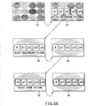
- a DVD video disc records video data (main picture) including video (moving picture) data as principal part of the recorded contents, and sub-picture data including auxiliary information such as superimposed dialogs and the like.
- the VMG menu or VTS menu is formed by some video data (still picture or short movie), and buttons (visual markers used by the user to select a selection item in the menu) using sub-picture data.
- a menu background and menu selection items are displayed by a still picture of main picture data, and a specific portion of sub-picture data is emphasized and displayed in a predetermined color, so that the user can visually recognize a specific menu selection item.
- the emphasized display portion using the sub-picture data serves as a button. The user can select a desired selection item using the button.
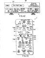
- a button is formed by a frame that fringes one of the five mini screens in a specific color (e.g., green). This green button frame can move on the menu by operating cursor keys of a remote controller of a DVD video player.
- the user wants to play back the movie from chapter 3, he or she moves the green button frame to a position where the frame surrounds the mini picture of chapter 3 by operating cursors.
- the color of the button frame that surrounds the mini picture of chapter 3 changes from green to another color (e.g., red), and the user can confirm that selection of chapter 3 has been settled.
- the DVD player searches for the recorded position of chapter 3, and starts video playback from chapter 3.
- the aforementioned chapter search can be implemented by the visual menu that uses the main picture background and sub-picture button. That is, when a plurality of dedicated menu pictures (mini pictures described above) obtained by adding a sub-picture button to normal video data are prepared, the user can play back the scene of the selected chapter by selecting the button.
- a digital information recording/playback system of the present invention uses at least thumbnail picture control information as control information upon recording/playing back video data and the control information.
- the thumbnail picture control information includes information for generating a thumbnail picture generated based on contents of the video data, and information for using the generated thumbnail picture in a menu corresponding to the contents of the video data.
- a digital information recording medium of the present invention which records video data and control information, includes at least thumbnail picture control information as the control information; and the thumbnail picture information includes information for generating a thumbnail picture generated based on contents of the video data, and information for using the generated thumbnail picture in a menu corresponding to the contents of the video data.
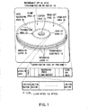
- FIG. 1 is a perspective view for explaining the structure of recordable optical disc 10 used in the DVD digital video recorder.
- optical disc 10 has a structure obtained by adhering a pair of transparent substrates 14 each having recording layer 17 using adhesive layer 20.
- Each substrate 14 can be formed of a 0.6-mm thick polycarbonate film, and adhesive layer 20 can consist of a very thin (e.g., 40 ⁇ m to 70 ⁇ m thick) ultraviolet setting resin.
- adhesive layer 20 can consist of a very thin (e.g., 40 ⁇ m to 70 ⁇ m thick) ultraviolet setting resin.
- Optical disc 10 has center hole 22, and clamp areas 24 used to clamp optical disc 10 upon its rotation are formed around center hole 22 on the two surfaces of the disc.
- Center hole 22 receives the spindle of a disc motor when disc 10 is loaded into a disc drive device (not shown).
- Optical disc 10 is clamped at its clamp areas 24 by a disc clamper (not shown) during disc rotation.
- Optical disc 10 has information areas 25 that can record information such as video data, audio data, and the like around clamp areas 24.
- lead-out area 26 is assured on the outer periphery side. Also, lead-in area 27 is assured on the inner periphery side of area 25 that contacts clamp area 24. The area between lead-out and lead-in areas 26 and 27 is defined as data recording area 28.
- a recording track is continuously formed in, e.g., a spiral pattern.
- the continuous track is divided into a plurality of physical sectors, which have serial numbers.
- Various data are recorded on optical disc 10 using those sectors as recording units.
- Data recording area 28 serves as an actual data recording area, and records video data (main picture data) such as a movie or the like, sub-picture data such as superimposed dialogs, menus, and the like, and audio data such as words, effect sounds, and the like as recording/playback information in the form of similar pit trains (physical shapes or phase states that bring about optical change in laser reflected light).
- video data main picture data
- sub-picture data such as superimposed dialogs, menus, and the like
- audio data such as words, effect sounds, and the like as recording/playback information in the form of similar pit trains (physical shapes or phase states that bring about optical change in laser reflected light).
- each recording layer 17 can be formed by three layers, i.e., by sandwiching a phase-change recording material layer (e.g., Ge 2 Sb 2 Te 5 ) between two zinc sulfide ⁇ silicon oxide (ZnS ⁇ SiO 2 ) mixture layers.
- a phase-change recording material layer e.g., Ge 2 Sb 2 Te 5
- ZnS ⁇ SiO 2 zinc sulfide ⁇ silicon oxide
- recording layer 17 on the side of read-out face 19 can be formed by three layers including the aforementioned phase-change recording material layer.
- layer 17 on the side opposite to read-out face 19 need not be an information recording layer but may merely be a dummy layer.
- two recording layers 17 can comprise a single phase-change recording layer (on the side farther from read-out face 19; read/write), and a single semi-transparent metal reflection layer (on the side closer to read-out face 19; read-only).
- optical disc 10 is a write-once DVD-R
- a polycarbonate substrate is used, gold can be used as a reflection layer (not shown), and an ultraviolet setting resin can be used as a protection layer (not shown).
- an organic dye is used in recording layer 17.
- the organic dyes cyanine, squarilium, chroconic, and triphenylmenthane dyes, xanthene and quinone dyes (naphthoquinone, anthraquinone, and the like), metal complex dyes (phthalocyanine, porphyrin, dithiol complex, and the like), and so forth can be used.
- Data can be written on such DVD-R disc using a semiconductor laser having a wavelength of 650 nm and an output of around 6 to 12 mW.
- two recording layers 17 can comprise a single metal reflection layer (on the side farther from read-out face 19), and a single semi-transparent metal reflection layer (on the side closer to read-out face 19).
- pit trains are formed in advance on substrate 14 by a stamper, a reflection layer of a metal or the like is formed on the surface of substrate 14 on which the pit trains are formed, and the reflection layer is used as recording layer 17.
- a reflection layer of a metal or the like is formed on the surface of substrate 14 on which the pit trains are formed, and the reflection layer is used as recording layer 17.
- grooves as recording tracks are not particularly formed, and the pit trains formed on the surface of substrate 14 serve as tracks.
- read-only ROM information is recorded on recording layer 17 as an embossed pattern signal.
- no such embossed pattern signal is formed on substrate 14 having read/write (or write-once) recording layer 17, and a continuous groove is formed instead.
- a phase-change recording layer is formed on such groove.
- the phase-change recording layer in land portions is also used for information recording in addition to the groove.
- substrate 14 on the rear side viewed from read-out face 19 need not always be transparent to the read/write laser beam used.
- a label may be printed on the entire surface of substrate 14 on the rear side.
- a DVD digital video recorder (to be described later) can be designed to attain write many/read many (read/write) for a DVD-RAM disc (or DVD-RW disc), write once/read many for a DVD-R disc, and read many for a DVD-ROM disc.
- FIG. 1 also exemplifies the correspondence between data recording area 28 of optical disc (DVD-RAM) 10 and recording tracks of data recorded there.
- DVD-RAM optical disc
- disc 10 When disc 10 is a DVD-RAM (or DVD-RW), disc 10 itself is stored in cartridge 11 to protect its delicate disc surface.
- DVD-RAM disc 10 in cartridge 11 When DVD-RAM disc 10 in cartridge 11 is inserted into the disc drive of a DVD video recorder (to be described later), disc 10 is pulled out from cartridge 11, is clamped by the turntable of a spindle motor (not shown), and is rotated to face an optical head (not shown).
- disc 10 is a DVD-R or DVD-ROM
- disc 10 itself is not stored in cartridge 11, and bare disc 10 is directly set on the disc tray of a disc drive.
- Recording layer 17 of information area 25 is formed with a continuous data recording track in a spiral pattern.
- the continuous track is segmented into a plurality of logical sectors (minimum recording units) each having a given storage size, and data are recorded with reference to these logical sectors.
- the recording size per logical sector is determined to be 2,048 bytes (or 2 kbytes) which are equal to one pack data length (to be described later).
- Data recording area 28 is an actual data recording area, which similarly records management data, main picture (video) data, sub-picture data, and/or audio data.
- data recording area 28 of disc 10 can be segmented into a plurality of ring-shaped (annular) recording areas (a plurality of recording zones), although not shown.
- the disc rotational velocity varies in units of recording zones. However, within each zone, a constant linear or angular velocity can be set. In this case, an auxiliary recording area (free space) can be provided for each zone. These free spaces in units of zones may collectively form a reserve area for that disc 10.
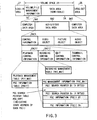
- FIG. 2 is a view for explaining an example of the hierarchical structure of information recorded on optical disc 10 (DVD-RAM or DVD-RW disc) shown in FIG. 1.
- optical disc 10 DVD-RAM or DVD-RW disc
- Lead-in area 27 includes an embossed data zone whose light reflection surface has an embossed pattern, a mirror zone whose surface is flat (mirror surface), and a rewritable data zone capable of information rewrites.
- Data recording area (volume space) 28 is comprised of volume/file management information 70 and data area DA, which can be rewritten by the user.
- Data area DA records computer data, video data, audio data, and the like.
- Volume/file management information 70 records file information of audio/video data recorded on data area DA, and information that pertains to the entire volume.
- Lead-out area 26 is also capable of information rewrites.
- the embossed data zone of lead-in area 27 records, for example, in advance:
- a DVD recording apparatus (a DVD video recorder or the like) can record information.
- Data area DA can record audio/video data DA2 and computer data DA1 and DA3 together.
- Data area DA can record computer data or audio/video data alone.
- Audio/video data area DA2 includes control information DA21, video object DA22, picture object DA23, and audio object DA24.
- Control information DA21 can include control information required upon executing various processes such as recording (video recording and/or audio recording), playback, edit, search, and the like.
- Video object DA22 can include information of the contents of recorded video data.
- Picture object DA23 can include still picture information such as still pictures, slide pictures, and the like.
- Audio object DA24 can include information of the contents of recorded audio data.
- recording information of the playback target (contents) of audio/video data is included in video object set VOBS (to be described later).
- Control information DA21 includes playback control information DA211, recording control information DA212, edit control information DA213, and thumbnail picture control information DA214.
- Playback control information DA211 includes control information required upon playback.
- Recording control information DA212 includes control information required upon recording (video recording and/or audio recording).
- Edit control information DA213 includes control information required upon edit.
- Thumbnail picture control information DA214 includes management information that pertains to thumbnail pictures used to search for a scene that the user wants to see in video data or those to be edited, and thumbnail picture data (corresponding to DA2143).
- Thumbnail picture control information DA214 can include anchor pointer DA2141, picture address table DA2142, and thumbnail picture data DA2143. (Anchor pointer DA2141 will be explained later.)
- Thumbnail picture control information DA214 can also include, as lower-layer information of picture address table DA2142 and thumbnail picture data 2143, menu index information INFO1, index picture information INFO2, slide & still picture information INFO3, information picture information INFO4, defective area information INFO5, and wallpaper picture information INFO6.
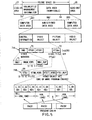
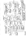
- FIG. 3 is a view for explaining the information hierarchical structure in FIG. 2 in more detail.
- FIG. 3 exemplifies the configuration of playback control information DA211.
- playback control information DA211 comprises playback management table PLY_MAT and program chain management table PGCIT. (Details of playback management table PLY_MAT will be described later.)
- Program chain management table PGCIT includes program chain management intonation PGC_MAI (to be described in detail later), program chain search pointer table PGC_SRPT consisting of one or more program chain information search pointers PGCI_SRP#1 to PGCI_SRP#n, and one or more pieces of program chain information PGCI#1 to PGCI#n (to be described in detail later).
- Each PGCI search pointer has a 4-byte size, and points to the start address of each program chain information PGCI.
- PGC designates the cell playback order, and indicates a unit for implementing playback of a series of cells. Each cell indicates a playback period that designates playback data by its start and end addresses.
- the playback order of contents of audio/video data area DA2 is determined by program chain PGC and cells.
- recording control information DA212 comprises recording management table REC_MAT (to be described in detail later).
- FIG. 4 exemplifies the correspondence between the cell configuration of a video object and program chain PGC in the information hierarchical structure shown in FIG. 2.
- This information hierarchical structure does not handle an information unit "video title set VTS" unlike a case (in case of a DVD video ROM) to be described later with reference to FIG. 5.
- the functions of video manager information VMGI and video title set information VTSI are combined into control information DA21.
- video object DA22 is comprised of video object set VOBS.
- This VOBS has contents corresponding to one or more program chains PGC#1 to PGC#k which respectively designate the cell playback order in different methods.
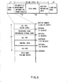
- FIG. 5 is a view for explaining the hierarchical structure of information recorded on optical disc (e.g., DVD-R disc) 10 shown in FIG. 1.
- optical disc e.g., DVD-R disc
- Data recording area 28 formed on optical disc 10 shown in FIG. 1 can have a structure shown in FIG. 5.
- the logical format of this structure is defined to comply with the ISO9660 and Universal Disc Format (UDF) Bridge as one of standard formats.
- Volume space 28 can include space (volume/file management information) 70 for information of the volume and file structures, and rewritable data area DA consisting of a space for audio/video applications (audio/video data), and a space for other applications (computer data).
- Volume space 28 is physically segmented into a large number of sectors, which have serial numbers.
- the logical addresses of data recorded on this volume space (data recording area) 28 mean logical sector numbers, as specified by the ISO9660 and UDF Bridge.
- the logical sector size in this space is 2,048 bytes (2 kbytes) as in the effective data size of the physical sector.
- the logical sector numbers are assigned serial numbers in ascending order of physical sector number.
- volume space 28 has a hierarchical structure, and includes volume/file management information 70, computer data area DA1, audio/video data area DA2, and computer data area DA3. These data areas are split up on the boundaries of logical sectors. Note that one logical sector is defined to be 2,048 bytes, and one logical block is also defined to be 2,048 bytes. Hence, one logical sector is defined equivalently with one logical block. Note that each physical sector is appended with error correction information and the like unlike logical sectors. For this reason, the physical sector size does not strictly match the logical sector size.
- Volume/file management information 70 corresponds to a management area defined by the UDF Bridge. Based on the description of this area 70, the contents of video manager VMG are stored in an internal system memory (not shown) of the DVD video recorder (to be described later).
- control information, video object, picture object, and audio object shown in FIG. 2 are allocated.
- the control intonation and video object respectively correspond to video manager VMG file 74A, and a file including one or more video title sets VTS#1 to VTS#n 72.
- video manager VMG consists of a plurality of files 74A.
- Each file 74A describes information (video manager information VMGI 75, video object set VMGM_VOBS for a video manager menu, video manager information backup file VMGI_BUP) for managing video title sets (VTS#1 to VTS#n) 72.
- Each video title set VTS 72 stores video data compressed based on the MPEG standard (a video pack to be described later), audio data compressed based on a predetermined standard or non-compressed audio data (an audio pack to be described later), and sub-picture data (a sub-picture pack to be described later; including bitmap data, one pixel of which is defined by a plurality of bits), and information for playing back these data (a navigation pack to be described later; including presentation control information PCI and data search information DSI).
- Video title set VTS 72 also consists of a plurality of files 74B as in video manager VMG.
- This file 74B includes video title set information VTSI 94, object set VTSM_VOBS for a video title set menu, video object set VTSTT_VOBS for a video title set title, and backup VTSI_BUP of video title set information.
- the number of video title sets VTS (VTS#1 to VTS#n) 72 is limited to a maximum of 99, and the number of files 74B that form each video title set VTS 72 is determined to be a maximum of 12. These files 74A and 74B are similarly split up at the boundaries of the logical sectors.
- Control information in a lower layer of audio/video data area DA2 corresponds to video manager information VMGI 75 and video title set information VTSI 94 in terms of its function.
- video object set VTSTT_VOBS for a video title set title defines a set of one or more video objects VOB.
- Each VOB defines a set of one or more cells.
- a set of one or more cells forms program chain PGC.
- PGC Assuming that one PGC corresponds to one drama, a plurality of cells that make up this PGC can be taken to correspond to various scenes in that drama.
- the contents of PGC (or contents of a cell) are determined by a software provider (or a software producer including the apparatus user) who produces the contents to be recorded on disc 10.
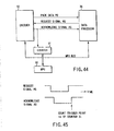
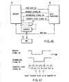
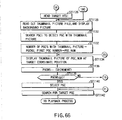
- FIG. 6 is a view for explaining information recorded on lead-in area 27 of optical disc 10.
- disc 10 When disc 10 is set in a DVD video recorder to be described later (or a DV video player; not shown), information in lead-in area 27 is read first.
- Lead-in area 27 records a predetermined reference code and control data in ascending order of sector number.
- the reference code in lead-in area 27 consists of two error correction code blocks (ECC blocks). Each ECC block has 16 sectors. These two ECC blocks (32 sectors) are generated by appending scramble data. Upon playing back the reference code appended with the scramble data, filter operation or the like on the playback side is done to play back a specific data symbol (e.g., 172) to assure precision in subsequent data reads.
- ECC blocks error correction code blocks
- Control data in lead-in area 27 is made up of 192 ECC blocks. In this control data field, the contents for 16 sectors in the respective blocks are repetitively recorded 192 times.
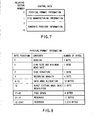
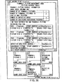
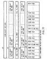
- FIG. 7 shows the contents of control data in lead-in area 27.
- This control data consisting of 16 sectors contains physical format information in the first sector (2,048 bytes), and disc manufacturing information and contents provider information in the subsequent sectors.
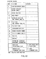
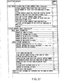
- FIG. 8 shows the contents of 2,048-byte physical format information contained in the control data shown in FIG. 7.
- the first byte position "0" describes the version of the DVD standard which the recording information complies with.
- the second byte position "1" describes the size (12 cm, 8 cm, or the like) of the recording medium (optical disc 10) and minimum read rate.
- the minimum read rate can be set at 1.5 to 1.8 Mbps using the reserved field.
- the third byte position "2" describes the disc structure (the number of recording layers, track pitch, type of recording layer, and the like) of the recording medium (optical disc 10). Based on the type of recording layer, it can be identified if that disc 10 is a DVD-ROM, DVD-R, or DVD-RAM (DVD-RW).
- the fourth byte position "3" describes the recording density (linear density and track density) of the recording medium (optical disc 10).
- the linear density indicates the recording length per bit (0.267 ⁇ m/bit, 0.293 ⁇ m/bit, or the like).
- the track density indicates the spacing between neighboring tracks (0.74 ⁇ m/track, 0.80 ⁇ m/track, or the like).
- the fourth byte position "3" includes a reserved field to designate other numerical values as linear and track densities for a DVD-RAM or DVD-R.
- the fifth byte position "4 to 15" describes the start and end sector numbers and the like of data area 28 of the recording medium (optical disc 10).
- the sixth byte position "16" describes a burst cutting area (BCA) descriptor.
- BCA burst cutting area
- the seventh byte position "17 to 20" describes a free space of the recording medium (optical disc 10).
- disc 10 is a single-sided, single-layered recording DVD-RAM disc
- information indicating 2.6 GB (or the number of sectors corresponding to this number of bytes) is described at this location of disc 10.
- disc 10 is a double-sided recording DVD-RAM disc
- information indicating 5.2 GB (or the number of sectors corresponding to this number of bytes) is described at that location.
- the eighth byte position "21 to 31" and the ninth byte position "32 to 2047" are reserved for future use.
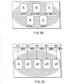
- FIG. 9 exemplifies the directory structure of information (data files) recorded on optical disc 10.
- the hierarchical structure shown in FIG. 5 When the hierarchical structure shown in FIG. 5 is adopted, the subdirectory of video title set VTS and that of audio title set ATS are linked under the root directory as in the hierarchical file structure adopted by a versatile operating system of a computer.
- Various video files (files VMGI, VMGM, VTSI, VTSM, VTS, and the like) are contained in the subdirectory of VTS and managed systematically.
- a specific file e.g., specific VTS
- the subdirectory of audio/video data stores (a) a file of control information DA21 in place of files of video manager information VMGI, video title set information VTSI, video manager menu data VMGM, and video title set menu data VTSM, and (b) files of video object DA22, picture object DA2, and audio object DA24 in place of video data VTS.
- a specific file (e.g., specific control information) can be accessed by designating the path from the root directory to that file.
- DVD-RAM (DVD-RW) disc 10 or DVD-R disc 10 shown in FIG. 1 may be pre-formatted to have the directory structure shown in FIG. 9, and pre-formatted discs 10 may be put on the market as unused discs (raw discs) for DVD video recording.
- the root directory of pre-formatted raw disc 10 can include a subdirectory named "video title set” or "audio/video data".
- This subdirectory can also include a menu data file (VMGM, VTSM, thumbnail picture control information DA214, or the like) for storing predetermined menu information.
- FIG. 10 shows the contents of directory records corresponding to the directory structure shown in FIG. 9.
- a read flag (or played back flag) indicating whether or not a specific recorded file (e.g., VTS_01_1.VOB in FIG. 9) has been read out once (or whether or not that file has been played back at least once previously) is described.
- the read flag for a file which is not yet read out is set at "0". If the file has been read out at least once, the read file of that file is set at "1".
- an archive flag (or permanent save flag) indicating whether or not a specific recorded file has contents to be saved permanently (or contents that are prevented from being erroneously erased) is described.
- the archive flag for a file which can be erased is set at "0".
- the archive flag for a file which is to be saved permanently without being erased is set at "1".
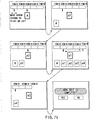
- FIG. 11 shows the hierarchical structure of information contained in video object set VTSTT_VOBS shown in FIG. 5.
- each cell 84 consists of one or more video object units (VOBU) 85.
- Each video object unit 85 is constituted as a set (pack sequence) of video packs (V packs) 88, sub-picture packs (SP packs) 90, and audio packs (A packs) 91 to have navigation pack (NV pack) 86 at the beginning of the sequence. That is, video object unit VOBU 85 is defined as a set of all packs recorded from certain navigation pack 86 to a pack immediately before the next navigation pack 86.
- Each of these packs serves as a minimum unit for data transfer.
- the minimum unit for logical processing is a cell, and logical processing is done in units of cells.
- Navigation pack 86 is built in each video object unit VOBU 85 to seamlessly or non-seamlessly change the angle to any one of various camera angles of multi-angle video data.
- the playback time of video object unit VOBU 85 corresponds to that of video data made up of one or more picture groups (groups of pictures; to be abbreviated as GOPs), and is set to fall within the range from 0.4 sec to 1.2 sec.
- GOPs picture groups
- One GOP is screen data which normally has a playback time of about 0.5 sec in the MPEG format, and is compressed to play back approximately 15 frame pictures during this interval.
- video object unit VOBU 85 When video object unit VOBU 85 includes video data, a video datastream is formed by arranging GOPs (complying with MPEG) each consisting of video packs 88, sub-picture packs 90, and audio packs 91. However, independently of the number of GOPs, video object unit VOBU 85 is defined with reference to the playback time of GOPs, and navigation pack 86 is always set at the beginning of unit 85 in the embodiment shown in FIG. 11.
- Video object unit VOBU 85 Even playback data consisting of audio data and/or sub-picture data alone is formed using video object unit VOBU 85 as one unit.
- video object unit VOBU 85 is formed by audio packs 91 alone to have navigation pack 86 at its beginning, audio packs 91 to be played back in the playback time of video object unit VOBU 85 to which the audio data belong are stored in that video object unit VOBU 85 as in video object VOB 83 of video data.
- a DVD video recorder can record video title set VTS containing VOBS 82 with the structure shown in FIG. 11 on optical disc 10, the user often wants to edit the recorded contents after this VTS is recorded.
- dummy packs 89 can be appropriately inserted in each VOBU 85. Each dummy pack 89 can be used to record edit data later.
- video object set (VTSTT_VOBS) 82 is defined as a set of one or more video objects (VOB) 83.
- Video objects VOB 83 in video object set VOBS 82 are used for the same purpose.
- VOBS 82 for a menu normally consists of one VOB 83, which stores a plurality of menu screen display data.
- VOBS 82 for a title set normally consists of a plurality of VOBs 83.
- VOBs 83 that form video object set VTSTT_VOBS for a title set correspond to picture data of the performance of that band.
- VOB 83 by designating given VOB 83, for example, the third tune in the concert of that band can be played back.
- VOB 83 that forms video object set VTSM_VOBS for a menu stores menu data of all the tunes performed in the concert of the band, and a specific tune, e.g., an expand, can be played back according to the menu display.
- one VOB 83 can form one VOBS 82 in a normal video program. In this case, a single video stream comes to an end in one VOB 83.
- a plurality of video streams (a plurality of video chains PGC) can be set in single VOB 82 in correspondence with the respective stories.
- the individual video streams are stored in corresponding VOBs 83.
- An audio stream and sub-picture stream pertaining to each video stream end in corresponding VOB 83.
- VOB 83 consists of one or a plurality of cells 84.
- a normal video stream consists of a plurality of cells, but a video stream for a menu often consists of single cell 84.
- Cells 84 are assigned identification numbers (C_IDN#j) like VOBs 83.
- information included in video object set VOBS in FIG. 4 is that obtained by removing navigation packs 86 from the hierarchical structure shown in FIG. 11.
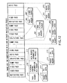
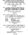
- FIG. 12 exemplifies a data sequence (pack sequence) in the pack format, which is obtained after data recorded on the optical disc 10 are read out, and undergo signal demodulation/error correction in a disc drive (not shown).
- This pack sequence includes navigation pack (control pack) 86, video packs 88, dummy packs 89, sub-picture packs 90, and audio packs 91. All these packs consist of data in units of 2 kbytes as in the logical sectors shown in FIG. 1.
- Navigation pack 86 includes pack header 110, playback control information/presentation control information (PCI) packet 116, and data search information (DSI) packet 117.
- PCI packet 116 is made up of packet header 112 and PCI data 113, and DSI packet 117 of packet header 114 and DSI data 115.
- PCI packet 116 contains control data used in non-seamless angle switching, and DSI packet 117 contains control data used in seamless angle switching.
- the angle switching means changes in angle (camera angle) of watching the object picture.
- the user can watch scenes from various angles, e.g., a scene that mainly captures a vocalist, a scene that mainly captures a guitarist, a scene that mainly captures a drummer, and the like in a performance scene of an identical tune (identical event).
- the angle is switched (changed) when the viewer can select angles in accordance with his or her favor, and when an identical scene automatically repeats itself with different angles in the flow of story (if the software producer/provider has programmed the story in such way; or if the user of the DVD video recorder to be described later edits in such way).
- the angles are set in the following cases: temporally discontinuous, non-seamless playback that presents an identical scene of different angles (for example, in a scene at the instant when a certain boxer throws a counterpunch, the camera angle is changed to another angle to play back a scene in which the counterpunch begins to be thrown), and temporally continuous, seamless playback that changes the angle between temporally continuous scenes (for example, at the instant when a certain boxer has made a counterpunch, the camera angle is changed to another angle to play back a scene in which the other boxer who got the punch is blown off).
- Video pack 88 is comprised of pack header 881 and video packet 882.
- Dummy pack 89 is comprised of pack header 891 and padding packet 890, and padding packet 890 of packet header 892 and padding data 893. Note that padding data 893 stores insignificant data.
- Sub-picture pack 90 is made up of pack header 901 and sub-picture packet 902.
- Audio pack 91 is made up of pack header 911 and audio packet 912.
- video packet 882 in FIG. 12 contains a packet header (not shown), which records a decoding time stamp (DST) and presentation time stamp (PTS).
- DST decoding time stamp
- PTS presentation time stamp
- Each of sub-picture packet 902 and audio packet 912 contains a packet header (not shown), which records a presentation time stamp (PTS).
- a pack sequence included in video object set VOBS recorded on DVD-RAM or DVD-RW optical disc 10 can be configured not to include any navigation packs 86 in FIG. 12.
- FIG. 72 shows an example of the structure of a pack sequence which does not include any navigation packs.
- FIG. 13 shows another example of the contents of lowermost layer packs in the hierarchical structure shown in FIG. 11 (when the present invention is applied to the structure shown in FIGS. 2 to 4, navigation packs 86 are removed).
- V1 pack 88A including a main picture pack (MPEG2 video) and V2 pack 88B including a search picture pack and the like are prepared as video packs.
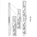
- FIG. 14 shows the structure for one dummy pack shown in FIG. 12. That is, one dummy pack 89 is made up of pack header 891, packet header 892 with a predetermined stream ID, and padding data 893 padded with a predetermined code. (Packet data 892 and padding data 893 form padding packet 890). The contents of padding data 893 in a non-used dummy pack have no specific meaning.
- This dummy pack 89 can be used as needed when the recorded contents are edited after predetermined recording is done on disc 10 shown in FIG. 1. Also, dummy pack 89 can be used to store thumbnail picture data (thumbnail data) DA2143 shown in FIG. 2, which is used for a user menu.
- DVD-RAM or DVD-RW
- thumbnail picture data for a menu which indicate the respective chapters of the video scenes recorded on a single disc, can be recorded as needed in V2 pack 88B in FIG. 13.
- each VOBU 85 that includes video pack 88 and the like has navigation pack 86 at its beginning (the structure shown in FIGS. 2 to 4 does not have any navigation pack).
- this navigation pack 86 contains presentation control information PCI and data search information DSI.
- PCI or DSI the playback procedure of each VOBU can be controlled (for example, discontinuous scenes can be automatically connected or a multiangle scene can be recorded).
- the above-mentioned postrecorded audio data or the like is written in padding data 893 of dummy pack 89 used as an audio pack.
- the additional comment is written in padding data 893 of dummy pack 89 used as a sub-picture pack.
- the inserted video picture is written in padding data 893 of dummy pack 89 used as a video pack.
- dummy pack 89 is a wildcard pack that can become any of audio, sub-picture, and video packs depending on its purpose.
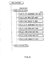
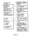
- FIG. 15 shows the contents of video manager VMG shown in FIG. 5.
- This VMG consists of a plurality of files 74A.
- Video manager VMG includes video manager information (VMGI) 75, object set (VMGM_VOBS) for a video manager menu, and backup (VMGI_BUP) of video manager information in correspondence with each file.
- VMGI video manager information
- VMGM_VOBS object set
- VMGI_BUP backup of video manager information in correspondence with each file.
- video manager information VMGI and backup VMGI_BUP of video manager information are mandatory items, and video object set VMGM_VOBS for displaying video manager information menu VMGM is optional.
- video manager information (VMGI) 75 set at the beginning of video manager VMG describes a video manager information management table (VMGI_MAT; mandatory), title search pointer table (TT_SRPT; mandatory), video manager menu program chain information unit table (VMGM_PGCI_UT; mandatory when VMGM_VOBS exists), parental management information table (PTL_MAIT; option), video title set attribute table (VTS_ATRT; mandatory), text data manager (TXTDT_MG; option), video manager menu cell address table (VMGM_C_ADT; mandatory when VMGM_VOBS exists), and video manager menu video object unit address map (VMGM_VOBU_ADMAP; mandatory when VMGM_VOBS exists) in this order.
- VMGI_MAT video manager information management table
- TT_SRPT title search pointer table
- VMGM_PGCI_UT video manager menu program chain information unit table
- PTL_MAIT parental management information table
- VTS_ATRT video title set attribute table
- TXTDT_MG text data manager
- addresses such as an end address (VMGI_MAT_EA) of video manager information management table VMGI_MAT, a start address (TT_SRPT_SA) of title search pointer TT_SRPT, and the like are described as the relative numbers of logical blocks from the head logical block that stores this table VMGI_MAT.
- Video manager information (VMGI) 75 contains information used upon playing back each video title set (VTS) 72 shown in FIG. 5, and such information is recorded on optical disc 10 to match a logical sector boundary.
- Video manager information menu video object set VMGM_VOBS stores menu information (managed by video manager VMG) which pertains to video data, audio data, and sub-picture data recorded on optical disc 10.
- VMGM_VOBS video manager information menu video object set
- the volume name of the optical disc to be played back, and audio and sub-picture comments upon displaying the volume name can be displayed. Also, selectable items can be displayed as sub-picture data.
- video manager information menu video object set allows to display a comment indicating that the optical disc to be played back contains as sub-picture data a video (in a single story or multi-story format) of matches fought by given boxer X until he finally winds the title of the world champion. That is, the fighting pose of boxer X is played back as video data together with the volume name such as "glorious history of boxer X" or the like, his theme (if any) is output as audio data, and the chronological table of his career/records and the like are displayed as sub-picture data.
- VMGM_VOBS VMGM video object set
- the viewer the user of the DVD video recorder; to be described later
- FIG. 15 also exemplifies some contents of video manager information management table VMGI_MAT. More specifically, video manager information management table VMGI_MAT describes free space (recordable amount) FREE_SPACE of optical disc 10, a user menu flag indicating if a user menu exists in optical disc 10, and various other kinds of information.
- video manager category VMG_CAT (not shown in FIG. 15) contained in video manager information management table VMGI_MAT describes video copy flags and audio copy flags of the video manager and video title sets. Depending on the contents of these flags, whether or not video and audio data can be copied are independently determined.
- Free space (recordable amount) FREE_SPACE shown in FIG. 15 equals free space data in the physical format information shown in FIG. 8, in non-used blank disc 10.
- the free space of disc 10 may be stored in either a file descriptor (physical format information) or management information (VMGI_MAT or the like).
- the disc free space after disc 10 is partially used to record can be written in FREE_SPACE in FIG. 15 and/or the free space field of the physical format information shown in FIG. 8 (in this case, that data is written in both FREE-SPACE and physical format information).
- this disc 10 has undergone video recording for 1 GB, information at the byte positions "17 to 20" in FIG. 8 indicates 2.6 GB or equivalent, but information in FREE_SPACE in FIG. 15 is rewritten to contents indicating approximately 1.6 GB or equivalent.
- this DVD video recorder initially reads the information at the byte positions "17 to 20" in FIG. 8 to detect that set disc 10 is a 2.6-GB disc, and then reads the information in FREE_SPACE in FIG. 15 to detect that the free space of set disc 10 is 1.6 GB. If all the data on this disc 10 are erased, the contents of FREE_SPACE in FIG. 15 and information in the free space field of the physical format information in FIG. 8 are rewritten to indicate 2.6 GB or equivalent.
- FIG. 16 is a table for explaining the contents of title search pointer table TT_SRPT shown in FIG. 15.
- This title search pointer table TT_SRPT records information such as title search pointer information TT_SRPTI, title playback type TT_PB_TY, the number AGLNs of angles, the number PTT_Ns of part-of-titles (chapters), a parental ID field, video title set number VTSN, video title set title number VTS_TTN, video title set start address VTS_SA, a user title menu flag, a main PGC number, a display position (X, Y), and the like.
- the user title menu flag is set at "01"; if no user title menu is available, the user title menu flag is set at "00".
- the main PGC number is written with a PGC number that includes a representative thumbnail picture used for the user title menu.
- the display position (X, Y) is written with the X-Y coordinates of a thumbnail picture on the user title menu screen.
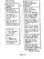
- FIG. 17 shows the contents of video title set VTS 72 in FIG. 5.
- Video title set VTS consists of a plurality of files 74B like video manager VMG shown in FIG. 15.
- Each file 74B contains video title set information (VTSI) 94, object set (VTSM_VOBS) for a video title set menu, video object sets (VTSTT_VOBS; nine files in maximum) for video title set titles, and backup (VTSI_BUP) for video title set information.
- VTSI video title set information
- VTSM_VOBS object set
- VTSTT_VOBS nine files in maximum
- VTSI_BUP backup
- video title set information VTSI 94 set at the beginning of video title set VTS 72 describes a video title set information management table (VTSI_MAT; mandatory), a title search pointer table (VTS_PTT_SRPT; mandatory) for a video title set part-of-title (e.g., chapter of a program), a video title set program chain information table (VTS_PGCIT; mandatory), a video title set menu program chain information unit table (VTSM_PGCI_UT; mandatory when VTSM_VOBS is present), a video title set time map table (VTS_TMAPT; option), a video title set menu cell address table (VTSM_C_ADT; mandatory when VTSM_VOBS is present), a video title set menu video object unit address map (VTSM_VOBU_ADMAP; mandatory when VTSM_VOBS is present), a video title set cell address table (VTS_C_ADT; mandatory), and a video title set video object unit address map (VTS_VOBU_ADMAP;
- FIG. 17 also shows some contents of video title set information management table VTSI_MAT. That is, this video title set information management table VTSI_MAT describes a played back flag (PLAY_END Flag) indicating whether or not a program recorded on optical disc 10 has been completely played back at least once, an archive flag (ARCHIVE Flag) which serves to prevent erase errors when a program recorded on optical disc 10 is to be saved without being erased, and various other information.
- PLAY_END Flag indicating whether or not a program recorded on optical disc 10 has been completely played back at least once
- an archive flag ARCHIVE Flag
- FIG. 18 is a table for explaining the contents of playback management table PLY_MAT shown in FIG. 3.
- This playback management table PLY_MAT records identifier ID of data which is to undergo playback management, start address VOBS_SA of a video object set, end address VOBS_EA of a video object set, end address CTLI_EA of control information, end address PLYCI_EA of playback control information, category CAT of data which is to undergo playback management, video attribute V_ATR, the number AST_Ns of audio streams, audio stream attribute AST_ATRT, the number SPST_Ns of sub-picture streams, sub-picture stream attribute SPST_ATRT, a user menu flag, a main PGC number, a display position (X, Y), a playback end flag, and the like.
- the user title menu flag is set at "01"; if no user title menu is available, the user title menu flag is set at "00".
- the main PGC number is written with a PGC number that includes a representative thumbnail picture used for the user title menu.
- the display position (X, Y) is written with the X-Y coordinates of a thumbnail picture on the user title menu screen.
- FIG. 19 is a table for explaining the contents of recording management table REC_MAT shown in FIG. 3.
- This recording management table REC_MAT describes end address RECI_EA of recording control information, end address REC_MAT_EA of recording management table REC_MAT, free space FREE_SPACE, an archive flag, and the like.
- Free space FREE_SPACE stores the remaining recordable size on disc 10 after the user has recorded or erased various data.
- FIG. 20 is a table for explaining the contents of PGC management information PGC_MAI shown in FIG. 3.
- This PGC management information PGC_MAI includes end address PGCI_TABLE_EA of program chain information table PGCIT, end address PGC_MAI_EA of program chain management information, start address PGC_SRP_SA of a program chain search pointer, end address PGC_SRP_EA of a program chain search pointer, start address PGCI_SA of program chain information, end address PGCI_EA of program chain information, and the total number PGC_Ns of program chains.
- Program chain search pointer PGC_SRP points to the beginning of each program chain information PGCI, and a search for each PGCI can be easily executed using this pointer.
- FIG. 21 is a table for explaining the contents of PGC information PGCI shown in FIG. 3.
- This PGC information PGCI includes program chain general information PGC_GI, program chain program map PGC_PGMAP indicating the number of entries of programs, and one or more cell playback information CELL_PLY_INF#1 to CELL_PLY_INF#m.
- FIG. 22 is a table for explaining the contents of PGC general information PGC_GI shown in FIG. 21.
- This PGC general information PGC_GI includes program chain contents PGC_CNT, program chain playback time PGC_PB_TM, program chain audio stream control table PGC_AST_CTLT, program chain sub-picture stream control table PGC_SPST_CTLT, program chain navigation control PGC_NV_CTL, sub-picture color palette table PGC_SP_PTL, start address PGC_PGMAP_SA of a program chain program map, start address CELL_PLY_I_SA of cell playback information, the number CELL_Ns of cells used in a target program chain, a menu data flag of a program chain, a display position (X, Y), a playback end flag, an archive flag, and the like.
- the PGC menu data flag is set at "01"; if no menu data is available, the PGC menu data flag is set at "00".
- the display position (X, Y) is written with the X-Y coordinates upon displaying PGC menu data.
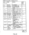
- FIG. 23 is a table for explaining the contents of cell playback information CELL_PLY_INF shown in FIG. 21.
- This cell playback information CELL_PLY_INF includes cell category C_CAT, cell playback time C_PBTM, a playback end flag, an archive flag, cell start address CELL_SA, cell end address CELL_EA, and the like.
- Cell start address CELL_SA is written with the start address of a period to be played back as a cell
- cell end address CELL_EA is written with the end address of that period.
- cell category C_CAT and cell playback time C_PBTM are used as cell general information (CELL_GI).
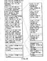
- FIG. 24 shows the contents of video title set program chain information table VTSI_PGCIT shown in FIG. 17.
- This video title set program chain information table VTS_PGCIT contains program title set program chain information table information (VTS_PGCITI), video title set program chain information search pointers (VTS_PGCI_SRP#1 to VTS_PGCI_SRP#n), and video title set program chain information (VTS_PGCI).
- VTS_PGCI the order of a plurality of pieces of video title set program chain information VTS_PGCI is set independently of that of the plurality of video title set program chain information search pointers VTS_PGCI_SRP#1 to VTS_PGCI_SRP#n.
- single program chain information VTS_PGCI can be indicated by one or more program chain information search pointers VTS_PGCI_SRP.
- FIG. 24 exemplifies the contents of video title set program chain information VTS_PGCI. That is, program chain information (PGCI) is made up of program chain general information (PGC_GI; mandatory), a program chain command table (PGC_CMDT; option), a program chain program map (PGC_PGMAP; mandatory when C_PBIT to be described below is present), a cell playback information table (C_PBIT; option), and a cell position information table (C_POSIT; mandatory when C_PBIT above is present).
- program chain information is made up of program chain general information (PGC_GI; mandatory), a program chain command table (PGC_CMDT; option), a program chain program map (PGC_PGMAP; mandatory when C_PBIT to be described below is present), a cell playback information table (C_PBIT; option), and a cell position information table (C_POSIT; mandatory when C_PBIT above is present).
- FIG. 24 also exemplifies the contents of cell playback information table C_PBIT.
- Each cell playback information C_PBI (C_PBI#1 to C_PBI#n) shown in FIG. 24 includes a cell category (C_CAT), cell playback time (C_PBTM), the start address (C_FVOBU_SA) of the first video object unit (VOBU) in the cell, the end address (C_FILVU_EA) of the first interleaved unit (ILVU) in the cell, the start address (C_LVOBU_SA) of the last video object unit (VOBU) in the cell, and the end address (C_LVOBU_EA) of the last video object unit (VOBU) in the cell, although not shown.
- C_CAT cell category
- C_PBTM cell playback time
- C_FILVU_EA) of the first interleaved unit (ILVU) in the cell the start address (C_LVOBU_SA) of the last video object unit (
- Cell category C_CAT can contain the following contents although not shown in FIG. 24. That is, this cell category (C_CAT) indicates the number of cell commands by the lower 8 bits (b0 to b7), the cell still time by the next 8 bits (b8 to b15); the cell type (e.g., karaoke or the like) by the next 5 bits (b16 to b20), an access denial flag by the next 1 bit (b21), the cell playback mode (e.g., movie or still) by the next 1 bit (b22), a seamless angle change flag by 1 bit (b24) after the next reserved bit, a system time clock STC discontinuity flag (to reset STC or not) by the next 1 bit (b25), an interleave/non-interleave flag (indicating if the cell designated by C_PBI is located in a continuous block or an interleaved block) by the next 1 bit (b26), a seamless playback flag (indicating if the cell designated by C_PBI is to be played back
- the cell block mode bits are 00b (b means binary), this means that the cell is not the one in the block; if the bits are 01b, the cell is the first one in the block; if the bits are 10b, the cell is the one in the block; and if the bits are 11b, the cell is the last one in the block.
- the cell block type bits are 00b, this indicates that the cell block does not belong to the block of interest; if the bits are 01b, the block of interest is an angle block (a block containing multiangle cells).
- the DVD video recorder can inform the viewer that playback of the angle block is currently in progress by flickering the angle mark (not shown; or by changing the ON color or shape of the angle mark). With such information, the viewer can make sure that an image in another angle is available for the picture which is currently being played back.
- the interleave/non-interleave flag is 0b, it indicates that the cell of interest belongs to a continuous block (that continuously records a plurality of VOBUs); if the interleave/non-interleave flag is 1b, the cell of interest belongs to an interleaved block (that records ILVUs each containing one or more VOBUs upon interleaving).
- one recording track of that disc is preferably assigned to recording of one interleaved block.
- track jump suffering less time lag (suitable for seamless angle change) can be attained.
- VOBU video object unit
- a time lag for a maximum of one revolution of the disc may be produced.
- the contents of the seamless angle change flag are normally determined in advance by the provider (the software producer who produces the program contents of titles recorded on optical disc 10). That is, by determining the contents of the seamless angle change flag in advance, the provider can uniquely determine whether the non-seamless angle change or seamless angle change is to be used.
- the seamless angle change flag represents whether the angle information described in navigation pack 86 indicates seamless or non-seamless angle information
- if the user has changed this flag he or she must also modify angle information (not shown) in navigation pack 86 (e.g., modification from seamless angle information to non-seamless angle information).
- the cell playback mode When the cell playback mode is 0b, it indicates continuous playback in the cell; if the mode is 1b, still playback in each VOBU present in the cell.
- the access denial flag can be used upon prohibiting direct selection by user operation. For example, when the access denial flag of a cell that records answers for a collection of questions, the user is prohibited from reading the answers by stealth.
- the cell type can indicate the following ones by its 5-bit contents, for example, when the cell of interest is formed for karaoke .
- the 5 bits are 00000b, no cell type is designated; if the 5 bits are 00001b, a title picture of the karaoke is designated; if the 5 bits are 00010b, an introduction part of the karaoke is designated; if the 5 bits are 00011b, a song part other than a climax (bridge) part is designated; if the 5 bits are 00100b, a song part of the first climax part is designated; if the 5 bits are 00101b, a song part of the second climax part is designated; if the 5 bits are 00110b, a song part for a male vocal is designated; if the 5 bits are 00111b, a song part for a female vocal is designated; if the 5 bits are 01000b, a song part for mixed voices is designated; if the 5 bits are 01001b, an interlude part (instrumental part) is designated; if the 5 bits are 01010b, fading-in of the interlude part is designated; if the 5
- angle change also applies to background video data of the karaoke .
- background video data of the karaoke For example, a full-figure shot, close-up shots of the face and mouth, and the like of a singer who is singing a guide vocal can undergo angle changes seamlessly along with the flow of a karaoke music or non-seamlessly by going back some bars, or during repeat playback between desired bars, as the viewer desired.
- the number of cell commands indicates the number of commands to be executed upon completion of playback of the cell of interest.
- FIG. 25 shows the contents of program chain general information PGC_GI shown in FIG. 24.
- program chain general information PGC_GI describes program chain contents (PGC_CNT), a program chain playback time (PGC_PB_TM), program chain user operation control information (PGC_UOP_CTL), a program chain audio stream control table (PGC_AST_CTLT), a program chain sub-picture stream control table (PGC_SPST_CTLT), program chain navigation control information (PGC_NV_CTL), a program chain sub-picture palette (PGC_SP_PLT), the start address (PGC_CMDT_SA) of a program chain command table, the start address (PGC_PGMAP_SA) of a program chain program map, the start address (C_PBIT_SA) of a playback information table of cells in the program chain, the start address (C_POSIT_SA) of a position information table of cells in the program chain, a program chain menu data flag, and a display position (X, Y).
- program chain contents PGC_CNT indicate the number of programs and number of cells (a maximum of 255) in that program chain. In a program chain having no video object VOB, the number of programs is "0".
- Program chain playback time PGC_PB_TM represents the total playback time of programs in that program chain in hours, minutes, seconds, and the number of video frames.
- This PGC_PB_TM also describes a flag (tc_ flag) indicating the type of video frame, and a frame rate (25 or 30 frames per sec) or the like is designated by the contents of this flag.
- Program chain user operation control information PGC_UOP_CTL indicates user operations prohibited in the program chain which is being played back.
- Program chain audio stream control table PGC_AST_CTLT can contain control information for each of eight audio streams.
- Each control information includes a flag (availability flag) indicating if the corresponding audio stream is available in that program chain, and conversion information from an audio stream number to an audio stream number to be decoded.
- Program chain sub-picture stream control table PGC_SPST_CTLT includes a flag (availability flag) indicating if that sub-picture stream is available in the program chain of interest, and conversion information from a sub-picture stream number (32) into the sub-picture stream number to be decoded.
- Program chain navigation control information PGC_NV_CTL includes Next_PGCN indicating the next program chain number to be played back after the program chain which is currently being played back, Previous_PGCN indicating a program chain number (PGCN) quoted by a navigation command "LinkPrevPGC” or "PrevPGC_Search()", GoUp_PGCN indicating a program number to which that program chain is to return, a PG Playback mode indicating the playback mode (sequential playback, random playback, shuffle playback, and the like) of the program, and a Still time value indicating the still time after that program chain is played back.
- PGCN program chain number quoted by a navigation command "LinkPrevPGC” or "PrevPGC_Search()
- GoUp_PGCN indicating a program number to which that program chain is to return
- PG Playback mode indicating the playback mode (sequential playback, random playback, shuffle playback, and the like) of the program
- a Still time value indicating the
- Program chain sub-picture palette PGC_SP_PLT describes 16 sets of luminance signals and two color difference signals used in a sub-picture stream in that program chain.
- Start address PGC_CMDT_SA of the program chain command table assures a description area for a pre-command executed before PGC playback, a post-command executed after PGC playback, and a cell command executed after cell playback.
- Start address PGC_PGMAP_SA of the program chain program map describes the start address of program map PGC_PGMAP representing the program configuration in the program chain by a relative address from the first byte of program chain information PGCI.
- Start address C_PBIT_SA of the cell playback information table in the program chain describes the start address of cell playback information table C_PBIT that determines the playback order of cells in that program chain by a relative address from the first byte of program chain information PGCI.
- Start address C_POSIT_SA of the position information table of cells in the program chain describes the start address of cell position information table C_POSIT indicating VOB identification numbers and cell identification numbers used in that program chain by a relative address from the first byte of program chain information PGCI.
- the PGC menu data flag describes whether or not a target program chain includes user menu data. If the target program chain includes user menu data, the PGC menu data flag is set at "01"; if no menu data is available, the PGC menu data flag is set at "00".
- the display position (X, Y) is written with X-Y coordinates upon displaying PGC menu data.
- program chain general information PGC_GI shown in FIG. 22 described above can be used in a DVD video recorder that records/plays back video using the data structure shown in FIGS. 2 to 4 (the one using a DVD-RAM disc or DVD-RW disc).
- program chain general information PGC_GI shown in FIG. 25 can be used in a DVD video recorder that records/plays back video using the data structure shown in FIG. 5 (the one using a DVD-R disc).
- FIG. 26 illustrates an example of a playback process of cell data recorded on the disc shown in FIG. 1.
- playback data is designated by the playback period from cell A to cell F.
- a playback combination of these cells in each program chain is defined by program chain information.
- FIG. 27 exemplifies the relationship between the program chain information and the cells shown in FIG. 26. More specifically, PGC#1 comprised of three cells #1 to #3 designates cell playback in the order of cell A ⁇ cell B ⁇ cell C. PGC#2 comprised of three cells #1 to #3 designates cell playback in the order of cell D ⁇ cell E ⁇ cell F. Furthermore, PGC#3 comprised of five cells #1 to #5 designates cell playback in the order of cell E ⁇ cell A ⁇ cell D ⁇ cell B ⁇ cell E.
- FIG. 28 is a view for explaining the first example of a method of determining a divide point of video contents recorded on the disc shown in FIG. 1.
- the divide points for individual PGCs exemplified in FIG. 27 are set based on a change in mode of the video-recording source.
- the video-recording source is television broadcast of a movie, which includes both stereo audio data for commercials and monaural audio (or bilingual audio) data.
- a point where the audio mode changes from stereo to monaural (or bilingual) or a point where the audio mode changes from monaural (or bilingual) to stereo can be automatically detected as the divide point of a PGC.
- FIG. 29 is a view for explaining the second example of a method of determining a divide point of video contents recorded on the disc shown in FIG. 1.
- the divide points for individual PGCs are set based on an elapse of a given video recording time. For example, every time a video recording time of 15 minutes has elapsed, the divide point of a PGC can be automatically detected independently of video-recorded contents.
- FIG. 30 is a view for explaining the third example of a method of determining a divide point of video contents recorded on the disc shown in FIG. 1.
- the divide points for individual PGCs are set based on a marker key input by the user. For example, when the user makes a marker key input at the time when he or she recognizes a scene change while reviewing the video-recorded contents, the divide point of a PGC is set at that time.
- FIG. 31 is a view for explaining the fourth example of a method of determining a divide point of video contents recorded on the disc shown in FIG. 1.
- the pause timing can be automatically detected as a divide point of a PGC.
- the pause timing can be automatically detected as a divide point of a PGC.
- FIG. 32 is a view for explaining the fifth example of a method of determining a divide point of video contents recorded on the disc shown in FIG. 1. For example, when the video-recorded contents have abruptly changed from a white frame (or field) to a black frame (or field) or vice versa, such abrupt change is detected.
- the detection point can be automatically detected as the divide point of a PGC.
- a moving picture and still picture can be used as a thumbnail picture used in the user menu of video-recorded contents.
- a moving picture no problem is posed since the normal MPEG video format can be used.
- a sequence end code must be inserted after I-picture.
- FIGS. 33 to 35 show some examples of the video pack structure of a portion to be played back as a still image in the video contents recorded on the disc shown in FIG. 1.
- FIGS. 33 to 35 also exemplify various insertion patterns of the sequence end code.
- sequence end code "000001B7" is appended at the end of I-picture to pack I-picture including a still picture for a user menu.
- a packet including sequence end code "000001B7" alone is appended.
- a padding packet is appended to that pack as needed so that the length per pack always becomes 2,048 bytes.
- the format of a user menu file can have the configuration, as shown in FIG. 36 and, more specifically, that shown in FIGS. 37 and 38.
- the user menu file describes data in the order of anchor points, a thumbnail picture management section, a backup (not shown) of the thumbnail picture management section, a group of thumbnail picture data, and anchor points, as exemplified from the top to the bottom in FIG. 36.
- This user menu file stores, as first data, pointer addresses called anchor points (a, p, b, q in FIG. 36), which respectively describe the start address (a) and end address (p) of the thumbnail picture management section, and the start address (b) and end address (q) of backup data of the thumbnail picture management section.
- anchor points a, p, b, q in FIG. 36
- thumbnail picture management section After the anchor points, the thumbnail picture management section is recorded, and this data has undergone a "32-kbyte align" process (to be described later).
- This thumbnail picture management section records data that pertains to thumbnail pictures which form the user menu.
- the start address and data length of a defective area are recorded if the file includes a defective area. Then, the registration number, start address, and the like of background picture data of the user menu are recorded.
- the backup of the thumbnail picture management section is recorded, although not shown. This backup is recorded as an insurance against damages to the thumbnail picture management section.
- thumbnail picture data After the backup, a group of actual packed thumbnail picture data are recorded. Note that each of these thumbnail picture data has been 32-kbyte aligned.
- the reason why data have been 32-kbyte aligned at the divisions of this file is to allow access in units of 32-kbyte ECC groups upon changing, adding, or deleting data. In this manner, higher-speed access can be achieved, and the operation load on a data process shown in FIGS. 39 to 41 (to be described later) can be reduced.
- each address information in this user menu file is expressed by a relative address from the beginning of the file.
- the user menu file shown in FIG. 36 has the following features:
- FIG. 36 is written with the contents exemplified in FIGS. 37 and 38.
- the first anchor pointer for a picture address table the start and end positions of the picture address table, and those of a reserved picture address table are described; as the picture address table (corresponding to DA2142 in FIG. 2), menu index information (INFO1), index picture information (INFO2), defective area information (INFO5), wallpaper picture information (INFO6), and padding data are described; and as the second anchor pointer for the picture address table, the start and end positions of the picture address table, and those of a reserved picture address table are described.
- picture address table shown in FIGS. 37 and 38 also describes slide & still picture information INFO3 and information picture information INFO4 in FIG. 2 as needed.
- the menu index information in FIG. 37 includes the number of index pictures, the number of information pictures, the number of slide & still pictures, the number of defective areas, and the number of wallpaper pictures.
- the index picture information in FIG. 37 includes a content characteristic, the ID of a program chain for an index picture, the time code of an index picture, the start position of an index picture, the number of used sectors upon recording an index picture, the picture size, the addresses of original audio/video data, and search text data.
- the index picture data used when a user menu picture is designated by only the address includes the content characteristic described with "0", the ID of a program chain for slide & still pictures, the addresses of original audio/video data, and the time codes of slide & still pictures, as shown in FIG. 38.
- the wallpaper picture information in FIG. 38 includes the number of wallpaper pictures that can be used as background pictures of the user menu (numbers of registered background pictures), the start position of a wallpaper picture, and the number of used sectors of an area where the wallpaper picture is recorded.
- the padding data in FIG. 38 includes the contents of index pictures, those of a defective area, those of a wallpaper picture, and the like.
- Data in the user menu file shown in FIGS. 36 to 38 are segmented in units of 32 kbytes as units (ECC groups) of an error correction code independently of the already recorded area or non-recorded area, and the positions of "ECC boundaries" as the boundaries of the segmented data are settled in advance.
- ECC groups units of an error correction code independently of the already recorded area or non-recorded area
- thumbnail picture data Upon recording the thumbnail picture data, anchor points, thumbnail picture management section, and backup of the thumbnail picture management section, all data are recorded so that their recording start and end positions match the "ECC boundary" positions.
- a "dummy area” is appended, as shown in FIG. 36, to match the recording end position with the "ECC boundary” position.
- This "dummy area” means the "padding" area shown in FIG. 37.
- thumbnail picture data Upon recording/erasing thumbnail picture data, information is recorded/erased in units of "ECC boundaries" described above. In this case, since information in a ECC group need not be partially changed, thumbnail data can be directly overwritten in correspondence with the ECC boundary upon recording data.
- the user menu file shown in FIG. 36 is designed in consideration of portability to another recording medium using a personal computer or the like.
- all the save addresses of the user menu thumbnail pictures, background picture, and thumbnail picture management area are expressed by differential addresses (relative addresses) from the start position of the user menu file.
- the relationship between the recorded thumbnail picture data and video signal can be recognized based on the correspondence between the pair of time code of the video signal and the start address.
- an unrecorded area or the location of erased thumbnail picture in the user menu file can be detected, and new thumbnail picture data can be recorded on that area.
- a defective area is managed in a link table between the locations on an AV file including audio/video data, and thumbnail picture recorded locations.
- anchor point information is read to check the backup data address of the thumbnail picture management section, and the backup data of the thumbnail picture management section is read.
- thumbnail picture recorded location link table in FIG. 36 is searched for an unrecorded area in the user menu file.
- Thumbnail picture data is recorded on the unrecorded area in the user menu file, and the anchor point address information is updated.
- the damaged location of the thumbnail picture management section due to dust or scratch on the disc (recording medium) surface is registered as a defective area in the thumbnail picture recorded location link table in FIG. 36.
- closed caption data, teletext data, or the like is often superposed on an original picture of thumbnail picture data used in the user menu.
- a thumbnail picture may be formed.
- a thumbnail picture may be formed based on character data alone.
- a thumbnail picture for the user menu may be expressed by only a pointer to an original picture without storing any actual thumbnail picture data (this corresponds to the arrangement shown in FIG. 40 to be described later, in which a decoder generates and displays thumbnail pictures to prepare the user menu by hardware).
- FIG. 39 exemplifies the arrangement of an apparatus (DVD video recorder) which records/plays back digital moving picture information at a variable recording rate on the disc shown in FIG. 1 using information with the structure described above with reference to FIGS. 2 to 25.
- DVD video recorder digital video recorder
- the apparatus main body of the DVD video recorder shown in FIG. 39 is roughly constructed by a disc drive unit (32, 34, and the like) for rotating DVD-RAM (DVD-RW) disc 10, and reading/writing information to/from disc 10, encoder 50 on the video recording side, decoder 60 on the playback side, and microcomputer block 30 for controlling the operations of the apparatus main body.
- a disc drive unit 32, 34, and the like
- DVD-RW DVD-RAM
- Encoder 50 comprises ADC (analog-to-digital converter) 52, video encoder (V encoder) 53, audio encoder (A encoder) 54, sub-picture encoder (SP encoder) 55, formatter 56, and buffer memory 57.
- ADC analog-to-digital converter
- V encoder video encoder
- a encoder audio encoder
- SP encoder sub-picture encoder
- ADC 52 receives an external analog video signal + external analog audio signal from AV input 42, or an analog TV signal + analog audio signal from TV tuner 44.
- ADC 52 converts the input analog video signal into a digital signal at a sampling frequency of, e.g., 13.5 MHz and 8 quantization bits (4 : 4 : 4 in MPEG).
- luminance component Y, color difference component Cr (or Y-R), and color difference component Cb (or Y-B) are respectively quantized by 8 bits.
- ADC 52 converts luminance component Y of the input analog video signal into a digital signal at a sampling frequency of, e.g., 13.5 MHz and 8 quantization bits, and converts color difference component Cr (or Y-R) and color difference component Cb (or Y-B) into digital signals at a sampling frequency of 6.75 MHz and 8 quantization bits (4 : 2 : 2 in MPEG).
- ADC 52 converts the input analog audio signal into a digital signal at a sampling frequency of, e.g., 48 kHz and 16 quantization bits.
- ADC 52 When an analog video signal and digital audio signal are input to ADC 52, the digital audio signal passes through ADC 52. (The digital audio signal may undergo processes for reducing jitter alone, changing the sampling rate or the number of quantization bits, and the like without changing its contents.)
- a digital video signal component output from ADC 52 is supplied to formatter 56 via video encoder (V encoder) 53. Also, a digital audio signal component output from ADC 52 is supplied to formatter 56 via audio encoder (A encoder) 54.
- V encoder 53 has a function of converting the input digital video signal into a digital signal compressed at a variable bit rate by MPEG2 or MPEG1.
- a encoder 54 has a function of converting the input digital audio signal into a digital signal compressed at a fixed bit rate (or linear PCM digital signal) by MPEG or AC-3.
- a sub-picture signal component (sub-picture pack) in the DVD video signal can be extracted from a sub-picture encoder, e.g., a DVD video player with a sub-picture signal independent output terminal.
- Sub-picture data input to SP encoder 55 is arranged into a predetermined signal format, and is then supplied to formatter 56.
- Formatter 56 performs predetermined signal processes for the input video signal, audio signal, sub-picture signal, and the like while using buffer memory 57 as a work area, and outputs recording data that matches the format (file structure) described above with reference to FIGS. 2 to 25 to data processor 36.
- the contents of standard encoding for generating the recording data will be briefly explained. That is, when encoder 50 shown in FIG. 39 starts encoding, parameters (see step ST20 in FIG. 49; to be described later) required for encoding video (main picture) data and audio data are set.
- the main picture data is pre-encoded using the set parameters to compute an optimal code amount distribution to a predetermined average transfer rate (recording rate). Based on the code amount distribution obtained by pre-encoding, the main picture data is encoded. At this time, the audio data is encoded at the same time.
- pre-encoding when data compression is insufficient (when a desired video program cannot be stored in a DVD-RAM or DVD-R disc used to record data), if pre-encoding can be done again (for example, if the recording source is the one capable of read many such as a video tape, video disc, or the like), the main picture data is partially re-encoded, and the re-encoded main picture data portion replaces the previously pre-encoded main picture data portion.
- the main picture data and audio data are encoded, and the average bit rate value required for recording is reduced largely.
- parameters required for encoding the sub-picture data are set, and encoded sub-picture data is generated.
- the encoded main picture data, audio data, and sub-picture data are combined and converted into a data structure for video recording.
- CELL_PLY_INF cell playback information
- C_PBI cell playback information
- the structure of cells that construct a program chain shown in FIG. 4 or 5 attributes of main picture, sub-picture, and audio data, and the like are set (some pieces of such attribute information use information obtained upon encoding the individual data), and information management table information (VMGI_MAT in FIG. 15, VTSI_MAT in FIG. 17, or PLY_MAT in FIG. 18) containing various kinds of information is created.
- the encoded main picture data, audio data, and sub-picture data are segmented into packs each having a predetermined size (2,048 bytes or 2 kbytes).
- Dummy packs (FIG. 14) are inserted into these packs as needed. Packs other than the dummy packs describe time stamps such as a PTS (presentation time stamp), DTS (decoding time stamp), and the like as needed.
- PTS presentation time stamp
- DTS decoding time stamp
- VOB 83 constructed by a plurality of cells, as shown in FIG. 72.
- VOBS 82 (without navigation packs) which combines one or more VOBs 83 is formatted to the structure shown in FIGS. 2 to 4.
- VOBS 82 (with navigation packs, as shown in FIG. 11) which combines one or more VOBs 83 is formatted to the structure shown in FIG. 5.
- the disc drive unit that writes/reads (records and/or plays back) information to/from DVD disc 10 comprises disc changer 100, disc drive 32, temporal storage 34, data processor 36, and system time counter (or system time clock; STC) 38.
- Temporal storage 34 is used to buffer a predetermined amount of data of those to be written in disc 10 via disc drive 32 (i.e., data output from encoder 50), and to buffer a predetermined amount of data of those played back from disc 10 via disc drive 32 (i.e., data input to decoder 60).
- temporal storage 34 when temporal storage 34 is comprised of a semiconductor memory (DRAM) of 4 to 8 Mbytes, it can buffer recording or playback data for approximately 8 to 16 sec at an average recording rate of 4 Mbps.
- DRAM semiconductor memory
- temporal storage 34 when temporal storage 34 is comprised of a 16-Mbyte EEPROM (flash memory), it can buffer recording or playback data for approximately 32 sec at an average recording rate of 4 Mbps.
- temporal storage 34 is comprised of a 100-Mbyte very compact HDD (hard disc), it can buffer recording or playback data for 3 min or more at an average recording rate of 4 Mbps.
- Temporal storage 34 can also be used to temporarily store recording information until disc 10 is exchanged by a new one, when disc 10 has been fully recorded during video recording.
- temporal storage 34 can be used to temporarily store data that excesses data to be read out from a normal drive within a predetermined period of time.
- read data upon playback is buffered on temporal storage 34, even when an optical pickup (not shown) produces read errors due to a vibration shock or the like, playback data buffered on temporal storage 34 can be used alternatively, thus preventing the played back picture from being interrupted.
- the EEPROM may be sold as an optional IC card.
- the HDD can be sold as an optional expansion drive.
- a DVD video recorder is implemented by software using a personal computer shown in FIG. 48 (to be described later)
- the free space of a hard disc drive or a main memory of the personal computer can be partially used as temporal storage 34 in FIG. 39.
- Data processor 36 in FIG. 39 supplies DVD recording data output from encoder 50 to disc drive 32, receives a DVD playback signal played back from disc 10 via drive 32, rewrites management information (the directory record in FIG. 10, VMGI_MAT in FIG. 15, VTSI_MAT in FIG. 17, PLY_MAT in FIG. 18, and the like) recorded on disc 10, and erases data recorded on disc 10 under the control of microcomputer block 30.
- management information the directory record in FIG. 10, VMGI_MAT in FIG. 15, VTSI_MAT in FIG. 17, PLY_MAT in FIG. 18, and the like
- Microcomputer block 30 includes an MPU (or CPU), a ROM written with control programs and the like, and a RAM that provides a work area required for executing programs.
- MPU or CPU
- ROM read-only memory
- RAM random access memory
- the MPU in microcomputer block 30 executes free space detection (ST12 in FIG. 49 and the like), recording amount (the number of recorded packs) detection (see FIGS. 44 to 47), remaining amount detection (ST420A in FIG. 51 and the like), warning (see FIG. 57), recording mode change instruction, and other processes (FIGS. 40 to 56 or FIGS. 58 to 67) using the RAM as a work area in accordance with the control programs stored in the ROM.
- the contents (FIG. 57, FIGS. 68 to 71, or the like) that the DVD video recorder user is informed of are displayed on display 48 of the DVD video recorder, or are displayed on a monitor display (FIG. 57) in an on-screen display (OSD) mode.
- OSD on-screen display
- control timings that MPU 30 controls disc changer 100, disc drive 32, data processor 36, and encoder 50 and/or decoder 60 can be determined based on time data output from STC 38 (video recording/playback operations are normally done in synchronism with time clocks from STC 38, but other processes may be executed at timings independently of STC 38).
- Decoder 60 comprises separator 62 for separating and extracting packs from DVD playback data with the pack structure shown in FIGS. 11 to 13 or FIG. 72, memory 63 used upon signal processes such as pack separation and the like, video decoder (V decoder) 64 for decoding main picture data (the contents of video pack 88, 88A, or 88B) separated by separator 62, sub-picture decoder (SP decoder) 65 for decoding sub-picture data (the contents of sub-picture pack 90) separated by separator 62, audio decoder (A decoder) 68 for decoding audio data (the contents of audio pack 91) separated by separator 62, video processor 66 for synthesizing sub-picture data output from SP decoder 65 with video data output from V decoder 64, as needed, and outputting main picture data with superimposed sub-picture data such as menus, highlight buttons, superimposed dialog, and the like, video digital-to-analog converter (V ⁇ DAC) 67 for converting a digital
- V ⁇ DAC 67 and analog audio signal from A ⁇ DAC 67 are supplied to external components (not shown; a multichannel stereophonic apparatus having two to six channels + monitor TV or projector) via AV output 46.
- OSD data output from MPU 30 is input to separator 62 of decoder 60, and is then input to video processor 66 through V decoder 64 (without being decoded).
- the OSD data is superimposed on main picture data, and these data are supplied to an external monitor TV connected to AV output 46. Then, a warning message shown in, e.g., FIG. 57 is displayed together with a main picture.
- FIG. 40 is a block diagram for explaining an example of an apparatus (DVD video recorder) which records/plays back information with the structure described above with reference to FIGS. 2 to 4 on the disc shown in FIG. 1 at a variable recording rate, and has a function of creating a user menu.
- DVD video recorder DVD video recorder
- Data processor 36 can directly access large-capacity temporary storage 34A.
- Encoder 50 includes thumbnail video encoder for generating a thumbnail picture used in a user menu upon encoding, and memory (RAM) 59 which is used as a work area upon encoding a thumbnail picture. This memory 59 is used to save thumbnail pictures for the user menu.
- Decoder 60 includes circuit block 600 that integrates the functions of separator 62, V decoder 64, SP decoder 65, and A decoder 68 in FIG. 39, video processor 66 for processing video and sub-picture data decoded by circuit block 600, and audio DAC & digital audio output interface 69 for converting audio data (digital) decoded by circuit block 600 into an analog signal, and outputting the analog audio signal.
- the apparatus shown in FIG. 40 further comprises, on the decode side, video mixer (V mixer) 602, frame memory 604, and video DAC & digital video output interface 67 for converting video data (digital) mixed with user menu data as needed by V mixer 602 into an analog signal, and outputting the analog video signal.
- V mixer video mixer
- frame memory 604 frame memory 604
- video DAC & digital video output interface 67 for converting video data (digital) mixed with user menu data as needed by V mixer 602 into an analog signal, and outputting the analog video signal.
- MPU 30 supplies encode setting data to encoder 50, and receives PGC division information (see descriptions of FIGS. 28 to 32) from encoder 50.
- MPU 30 receives thumbnail picture data used in the user menu from V mixer 602, and supplies text data to be displayed on the user menu, a menu display move command, and background picture data of the user menu if required to V mixer 602.
- Text data supplied from MPU 30 to V mixer 602 can be input from key input unit 49. This text data can be used as a query keyword.
- the data processes in the apparatus in FIG. 40 can be classified into two processes, i.e., a video recording process and playback process.
- MPU 30 In the video recording process, upon receiving a video recording command (e.g., an ON event of a video recording button of a remote controller or the like) from the user, MPU 30 loads management data from disc drive 32, and determines a write area on disc 10 set in the drive. MPU 30 then sets a management area to write the determined area, and sets the write start address of video data in disc drive 32, thus preparing for data recording.
- a video recording command e.g., an ON event of a video recording button of a remote controller or the like
- MPU 30 then resets a timer of STC 38.
- STC 38 is a system timer, and video recording/playback is done with reference to this timer value.
- PGC division setups are also made.
- MPU 30 sets the divide time interval to be 15 min, as shown in FIG. 29.
- MPU 30 executes that setup for encoder 50. Furthermore, MPU 30 makes various other required setups.
- An external AV signal input from TV tuner 44 or AV input 42 is A/D-converted into digital signals.
- a digital video signal is input to V encoder 53 and thumbnail video encoder 58.
- a digital audio signal is input to A encoder 54.
- TV tuner 44 inputs a text signal such as a closed caption signal, teletext signal, or the like to SP encoder 55.
- a mode change signal of source data for PGC division (stereo/monaural signal, picture aspect change signal, or the like) is input from TV tuner 44 to encoder 50.
- the respective encoders compress and packetize the input signals (video, audio, and sub-picture). (Note that packets are segmented and packetized to have a size of 2,048 bytes per pack.) These compressed signals are input to formatter 56. Formatter 56 determines and records presentation time stamp PTS and decoding time stamp DTS of each packet in accordance with the timer value from STC 38 as needed.
- packets of thumbnail pictures used in the user menu are transferred to and temporarily saved in memory 59 for storing thumbnail pictures.
- the size of each thumbnail picture on the user menu is selected to be, e.g., approximately 144 pixels ⁇ 96 pixels.
- MPEG2 compression which is the same as the compression format of main picture data, can be used as that of thumbnail pictures, but other compression schemes may be used.
- Formatter 56 temporarily saves packet data in buffer memory 57, then packs the input packet data to mix them in units of GOPs of MPEG (no navigation pack is appended in the data structure shown in FIGS. 2 to 4), and transfers the packs to data processor 36.
- formatter 56 sends the PGC divide addresses to MPU 30 as PGC division information.
- Data processor 36 forms ECC groups by combining packs sent from formatter 56 in units of 16 packs, appends error correction information to each ECC group, and sends these ECC groups to disc drive 32.
- ECC group data appended with error correction information are transferred to temporary storage 34A, and are temporarily stored therein until drive 32 is ready to record.
- recording of data stored in temporary storage 34A on disc 10 starts.
- MPU 30 Upon completion of video recording based on the data structure shown in FIGS. 2 to 4, MPU 30 generates and records PGC information table PGCIT (see FIGS. 20 and 21) in playback control information DA211 (see FIG. 3) in accordance with the PGC divide address information previously received from encoder 50.
- PGC information table PGCIT see FIGS. 20 and 21
- DA211 see FIG. 3
- MPU 30 can access data processor 36 via an MPU bus to read/write contents of a file management area and the like. With this access, MPU 30 can make a read/write from/to a track buffer in data processor 36.
- thumbnail picture data for the user menu may be inserted into recording data as independent video pack data in place of an independent file. That is, as shown in FIG. 13, the DVD video format specifies "0" (stream ID: 0E0h) as a stream number for main picture data, and can also specify "1" (stream ID: 0E1h) as that for thumbnail picture data and multiplex such stream.
- this file serves as an independent file used upon creating a user menu file (to be described later).
- This independent file can also be a source file used in the user menu edit process.
- first frame data of PGC is encoded by thumbnail video encoder 58 as source data of a thumbnail picture, and the encoded data is stored in memory 59.
- thumbnail video encoder 58 As source data of a thumbnail picture, and the encoded data is stored in memory 59.
- a packet data group stored in memory 59 is recorded on disc 10.
- MPU 30 Upon receiving a playback start command by user's operation, MPU 30 loads the management area of disc 10 from disc drive 32 via data processor 36, and determines the playback address.
- MPU 30 then sends the previously determined address of playback data and a read command to disc drive 32.
- Disc drive 32 reads out sector data from disc 10 in accordance with the received command, and data processor 36 makes error correction of the readout data and sends them to decoder 60 in the form of pack data.
- the separator in circuit block 600 receives the readout pack data and packetizes them. Then, video packet data (MPEG video data) is transferred to the video decoder, audio packet data to the audio decoder, and sub-picture packet data to the SP decoder in correspondence with the data purposes.
- video packet data MPEG video data
- audio packet data to the audio decoder
- sub-picture packet data to the SP decoder in correspondence with the data purposes.
- presentation time stamp PTS of each packet is loaded to STC 38.
- the respective decoders in circuit block 600 execute playback processes in synchronism with the PTS value in packet data (while comparing PTS and STC values), thus displaying a moving picture with audio and superimposed dialog on a TV monitor (not shown).
- thumbnail picture file previously saved as an independent file is flowed as stream packs, and is displayed by designating display positions (X- and Y-coordinate values) in frame memory 604.
- display positions X- and Y-coordinate values
- text data or the like is included, text is displayed below each thumbnail picture using a character ROM (or kanji ROM).
- FIG. 41 is a block diagram for explaining another example of an apparatus (DVD video recorder) which records/plays back information with the structure described above with reference to FIGS. 2 to 4 on the disc shown in FIG. 1 at a variable recording rate, and has a function of creating a user menu.
- DVD video recorder DVD video recorder
- FIG. 41 includes large-capacity temporary storage 34B, video mixer 602, frame memory (for two frames of text and video signals) 604, and the like.
- Video DAC/interface 67 and audio DAC/interface 69 shown in FIG. 40 are not shown in FIG. 41, but are also used in the arrangement in FIG. 41.
- Encoder 50 shown in FIG. 41 includes ADC 52 for converting analog video and audio signals from external AV input 42 or TV tuner 44 into digital signals, selector 53S for selecting one of a digital video signal from ADC 52 and thumbnail picture data from video mixer 602 and sending selected data to video encoder 53, video encoder 53 which uses buffer memory 57 as a work area, and formatter 56 for packing various data from audio data 54 and sub-picture encoder 55.
- ADC 52 for converting analog video and audio signals from external AV input 42 or TV tuner 44 into digital signals
- selector 53S for selecting one of a digital video signal from ADC 52 and thumbnail picture data from video mixer 602 and sending selected data to video encoder 53
- video encoder 53 which uses buffer memory 57 as a work area
- formatter 56 for packing various data from audio data 54 and sub-picture encoder 55.
- Decoder 60 shown in FIG. 41 includes separator 62 for separating a playback pack transferred from data processor 36 into main picture, sub-picture, and audio data, audio/sub-picture decoder 65/68 for expanding (decoding) audio and sub-picture data separated by separator 62 by a predetermined method, video decoder 64 for expanding (decoding) main picture data separated by separator 62 by a predetermined method, and thumbnail picture generator 64A for executing a process for displaying the decoded video stream as a thumbnail picture.
- MPU 30 Upon receiving a video recording command, MPU 30 loads management data from disc drive 32, and determines a write area in disc 10 (not shown). MPU 30 then sets a management area to write the determined area, and sets the write start address of video data in disc drive 32, thus preparing for recording data.
- MPU 30 resets the time of STC 30.
- STC 38 is a system timer, and video recording/playback is done with reference to this timer value.
- PGC division setups are also made.
- division conditions division at given time intervals (FIG. 29), division based on a stereo/monaural switching signal of an audio signal (FIG. 28), division based on a switching signal for aspect ratios 16 : 9 and 4 : 3 of an image mode, division based on a scene with an abrupt change in picture data which is determined upon encoding (FIG. 32), and the like may be used.
- MPU 30 sets the type of PGC division condition setup, and required parameters (e.g., the time interval upon division at given time intervals, or the like) in encoder 50. Furthermore, MPU 30 makes various other setups.
- selector 53S in encoder 50 is switched to the main picture selection side.
- a digital video signal obtained by A/D-converting by ADC 52 an external AV signal input from TV tuner 44 or AV input 42 is transferred to V encoder 53 via selector 53S.
- a digital audio signal A/D-converted by ADC 52 is transferred to A encoder 54. If broadcast from TV tuner 44 includes character/superimposed dialog information (characters such as closed caption, teletext, and the like), that text signal is transferred to SP encoder 55.
- a stereo/monaural signal (or stereo/bilingual signal) used in PGC division is input from TV tuner 44 to encoder 50.
- the respective encoders compress and packetize the input signals. (Note that packets are segmented and packetized to have a size of 2,048 bytes per pack.) These packetized signals are input to formatter 56. Formatter 56 determines and records presentation time stamp PTS and decoding time stamp DTS of each packet in accordance with the timer count value from STC 38 as needed.
- Formatter 56 temporarily saves packet data in buffer memory 57, and then packs the input packet data to mix them in units of GOPs of MPEG. Formatter 56 transfers a data stream appended with navigation packs at the head of each GOP as needed to data processor 36. At this time, the PGC divide address is sent to MPU 30 and is used as PGC division information.
- ECC group data appended with error correction information are transferred to temporary storage 34A, and wait until drive 32 is ready to record.
- recording of data stored in temporary storage 34A on disc 10 starts.
- MPU 30 Upon completion of video recording based on the data structure shown in FIGS. 2 to 4, MPU 30 generates and records PGC information table PGCIT (see FIGS. 20 and 21) in playback control information DA211 (see FIG. 3) in accordance with the previously received PGC divide address information.
- PGC information table PGCIT see FIGS. 20 and 21
- DA211 see FIG. 3
- MPU 30 can access data processor 36 via an MPU bus to read/write contents of a file management area and the like.
- MPU 30 Upon receiving a playback start command input by the user, MPU 30 loads the management area from disc drive 32 via data processor 36, and determines the playback address. MPU 30 then sends the determined address of playback data and a read command to disc drive 32.
- Disc drive 32 reads out sector data from disc 10 in accordance with the received command, and data processor 36 makes error correction of the readout data and sends them to decoder 60 in the form of pack data.
- separator 62 receives the readout pack data and packetizes them. Then, video packet data (MPEG video data) is transferred to V decoder 64, and audio/sub-picture packet data to A/SP decoder 65/68 in correspondence with the data purposes.
- MPEG video data MPEG video data
- presentation time stamp PTS of each packet is loaded to STC 38.
- the respective decoders 64, 65/68 execute playback processes in synchronism with the PTS value in packet data (while comparing PTS and STC values), thus displaying a moving picture with audio and superimposed dialog on a TV monitor (not shown).
- thumbnail picture data are transferred from V mixer 602 to V encoder 53 via selector 53S.
- the transferred thumbnail picture data are packetized by V encoder 53 and are packed by formatter 56, and pack data are recorded on disc 10 via data processor 36.
- thumbnail picture file saved as an independent file is flowed as stream packs, and is displayed by designating display positions in frame memory 604. At this time, if text data or the like is included, text is displayed below each thumbnail picture using a kanji ROM or the like.
- FIG. 42 shows the outer appearance of apparatus main body 200 of DVD video recorder shown in FIGS. 39 to 41, and an example of its front panel.
- disc tray inlet 202 shown in FIG. 42 opens forward.
- DVD-RAM or DVD-RW disc (a cartridge containing a disc) 10 or DVD-R disc (bare disc) 10 used in video recording is set on this disc tray.
- disc tray inlet 202 closes, and disc (e.g., DVD-RW) 10 set on the tray is loaded into disc drive 32 in apparatus main body 200.
- disc drive 32 is automatically started, and MPU 30 reads physical format information (including disc structure data, free space data of a blank disc, and the like) shown in FIG. 8.
- control information DA21 (including playback control information DA211, thumbnail control information DA214, and the like) shown in FIGS. 2 to 4.
- set disc 10 is a new DVD-RW disc (or DVD-RAM disc)
- an item "DVD-RW” on display unit (liquid crystal or fluorescent display panel) 48 of the DVD video recorder shown in FIG. 42 is displayed in an easy-to-see manner.
- a recording time "00 (hour) : 00 (min) : 00 (sec)” is displayed, and a recording title/chapter "00-00” is displayed (once video recording has been done, the recording title/chapter display changes like "01-01").
- MPU 30 detects it (e.g., YES in ST422A in FIG. 51), and an item "DISC TO BE CHANGED" that prompts the user to exchange the disc is displayed on display unit 48 in an easy-to-see manner.
- the front panel of DVD video recorder main body 200 also has basic operation keys such as a power switch button, open/close key, playback key, stop key, chapter/program skip key, rewind key, fastforward key, recording start button (not shown), and the like.
- basic operation keys such as a power switch button, open/close key, playback key, stop key, chapter/program skip key, rewind key, fastforward key, recording start button (not shown), and the like.
- FIG. 42 assumes a case wherein the DVD video recorder does not incorporate any disc changer 100 in FIG. 39 (i.e., disc changer 100 is connected to apparatus main body 200 in FIG. 42 as an optional external device via a SCSI cable or the like).
- the above-mentioned item "DISC TO BE CHANGED" begins to be lit up or flicker slightly before disc 10 set in the apparatus main body is used up during video recording. After that when the remaining amount of disc 10 becomes zero, video recording automatically proceeds to one or more DVD-RW discs 10 set in external disc changer 100.
- two or more DVD video recorders may be prepared, and their MPUs 30 may be connected by daisy chain via a communication cable to attain relay recording using two or more DVD video recorders.
- DVD video recorder shown in FIGS. 39 to 41 does not record any warning or messages to the user on disc 10.
- video recording information (video recording average bit rate, video recording channel number, video recording date/time, and the like) exemplified on the lower portion of the monitor screen shown in FIG. 57 may be recorded on disc 10 for several seconds immediately after the beginning of video recording.
- FIG. 43 shows an example of remote controller 5 used to operate the DVD video recorder shown in FIGS. 39 to 41. Fundamental operations may be made by operation keys provided to the front panel of DVD video recorder main body 200 shown in FIG. 42, but various kinds of operations that utilize the features of DVD are done by remote controller 5.
- the user menu is used. That is, when no root menu is available on the disc but the user menu is available, the user menu is used upon operation of the menu key.
- the title key when the title key is pressed, the title number and chapter number are displayed on a given portion (e.g., the upper left corner) of the screen.
- a predetermined period of time e.g., 3 sec
- the title number and chapter number to be searched out on display unit 48 are flickered to inform the user that a search is in progress.
- the recorded angle numbers are cyclically selected, and playback of the selected angle restarts.
- the recorded angle numbers are cyclically switched, and a still picture in the selected angle is played back.
- the video recording time can be further prolonged by selecting MPEG1/2 Mbps or MPEG1/1 Mbps.
- contents (1) and (2) may be simultaneously displayed, as will be exemplified in FIG. 57.
- FIG. 44 is a block diagram showing an example of a recording amount detection circuit (without transfer clocks) for detecting the number of recorded bytes of information recorded on disc 10 by counting the number of recorded bytes in the DVD video recorder shown in FIGS. 39 to 41.
- FIG. 45 is a timing chart for explaining the count timings of recorded bytes by counter 31 in FIG. 44.
- DVD recording data formatted by formatter 56 in encoder 50 in FIGS. 39 to 41 is formed by a sequence of a plurality of data packs (2,048 bytes per pack) 86 to 91, as shown in FIG. 11.
- data processor 36 sends request signal RS (upper signal in FIG. 45) for requesting transfer of data PD of the data packs to encoder 50.
- request signal RS upper signal in FIG. 45
- encoder 50 formatter 56
- acknowledge signal AS confirms reception of this request to data processor 36 (lower signal in FIG. 45).
- encoder 50 formatter 56
- Acknowledge signal AS is input to counter 31.
- Counter 31 counts up its contents by 1 in response to the leading edge (trigger point ta in FIG. 45) of signal AS, and holds the contents after the counting-up.
- the contents of counter 31 are sent back to MPU 30 via the MPU bus.
- MPU 30 detects the number of bytes (i.e., the number of bytes recorded on disc 10) transferred from encoder 50 (formatter 56) to data processor 36 on the basis of the contents (count value) of counter 31.
- the number of data (the number of bytes) transferred to data processor 36 represents the data amount recorded on disc 10.
- the remaining amount (the number of bytes that can be recorded) of disc 10 can be determined. Furthermore, when this remaining amount is divided by the average recording rate, the remaining time (indicating a predicted value of how much longer data can be recorded) of disc 10 can be determined.
- FIG. 46 is a block diagram showing another example of the recording amount detection circuit (with transfer clocks) for detecting the number of recorded bytes of information recorded on the disc in FIG. 1 by counting the number of recorded bytes in the DVD video recorder shown in FIGS. 39 to 41.
- FIG. 47 is a timing chart for explaining the count timings of recorded bytes by a counter in FIG. 46.
- transfer clock signal CK is output to encoder 50 every time pack data PD is transferred from encoder 50 to data processor 36.
- encoder 50 sends back acknowledge signal AS (middle signal in FIG. 47) to data processor 36.
- Acknowledge signal AS is not generated every time 1 byte is transferred, but is a gate signal which is active during the transfer period for the number of bytes to be transferred.
- Transfer clock signal CK (lower signal in FIG. 47) output from encoder 50 is sent to data processor 36 as a synchronization signal for byte transfer.
- Acknowledge signal AS is supplied to the first input of OR gate 33 as the gate signal.
- the second input of OR gate 33 receives transfer clock signal CK.
- OR gate 33 counts up its contents by 1 in response to each leading edge (each of a plurality of trigger points tb in FIG. 47) of transfer signal CK during the active (logical "0") period of acknowledge signal AS, and holds the contents after the counting-up.
- the contents of counter 31 are sent back to MPU 30 via the MPU bus.
- MPU 30 detects the number of bytes (the number of recorded bytes) transferred from encoder 50 to data processor 36 on the basis of the contents (count value) of counter 31.
- the contents of counter 31 represent the data amount recorded on disc 10. By subtracting (count value bytes) from the free space of disc 10, the remaining amount of disc 10 can be determined. Furthermore, when this remaining amount is divided by the average recording rate, the remaining time of disc 10 can be determined.
- FIG. 48 is a block diagram for explaining the recording/playback function of the DVD video recorder shown in FIGS. 39 to 41 implemented using a versatile personal computer.
- Personal computer 1000 shown in FIG. 48 may use dedicated hardware, or a versatile personal computer with a general arrangement.
- main CPU 1004 basic I/O system ROM (BIOS ⁇ ROM) 1008, main memory 1010, video memory 1012, floppy disc drive (FDD) 1022, keyboard I/O device 1024, mouse I/O device 1026, communication I/O device 1028, and the like.
- Main CPU 1004 is directly connected to cache memory 1006 via a dedicated high-speed bus.
- Internal bus 1002 of personal computer 1000 has a plurality of versatile bus slots (not shown). These slots receive SCSI interface (SCSI board) 1014, DVD processor board 1030, video I/O device (video card) 1032, audio I/O device (audio card) 1034, and the like.
- SCSI board SCSI interface
- DVD processor board DVD processor board
- video I/O device video card
- audio I/O device audio card
- SCSI board 1014 is connected with SCSI hard disc drive (HDD) 1018, and SCSI DVD-ROM/DVD-RAM compatible drive 1020 (drive 1020 may also be compatible with a CD).
- HDD hard disc drive
- SCSI DVD-ROM/DVD-RAM compatible drive 1020 drive 1020 may also be compatible with a CD.
- Video card 1032 is connected with high-resolution bitmap display (analog RGB type) 6, and audio card 1034 is connected with a pair of 2-channel stereophonic loudspeakers 8 (if card 1034 has no power amplifier, the power amplifier may be incorporated in loudspeakers 8 or a stereophonic amplifier (not shown) may be inserted between card 1034 and loudspeakers 8).
- high-resolution bitmap display analog RGB type
- audio card 1034 is connected with a pair of 2-channel stereophonic loudspeakers 8 (if card 1034 has no power amplifier, the power amplifier may be incorporated in loudspeakers 8 or a stereophonic amplifier (not shown) may be inserted between card 1034 and loudspeakers 8).
- DVD processor board 1030 in FIG. 48 has hardware corresponding to devices 38, 50, 60, and the like shown in FIGS. 39 to 41.
- Disc drive 32 shown in FIGS. 39 to 41 corresponds to DVD-ROM/RAM drive 1020 in FIG. 48.
- the storage area of memory 1010 or video memory 1012 in FIG. 48 may be partially used as temporal storage 34 (or 34A/34B), buffer memory 57, or memory 63 of the separator in FIGS. 39 to 41, as needed.
- hard disc 1018 in FIG. 48 can also be partially used as temporal storage 34 (or 34A/34B) in FIG. 39 to 41. If hard disc 1018 is a disc having a storage size as large as several Gbytes (e.g., 3 to 5 GB), a predetermined area (for 2.6 GB) in this disc may be partitioned and may be used as virtual DVD-RAM (or DVD-RW or DVD-R) disc 10.
- the functions of the operation keys of DVD video recorder main body 200 in FIG. 42 can be assigned to a keyboard (not shown) connected to keyboard I/O device 1024 in FIG. 48. Also, the functions of various keys (buttons and cursors) of remote controller 5 in FIG. 43 can be assigned to a keyboard (not shown) connected to keyboard I/O device 1024 in FIG. 48, a mouse (not shown) connected to mouse I/O device 1026, or an external controller (not shown) connected to communication I/O device 1028.
- Typical data processing in the DVD video recorder shown in FIGS. 39 to 41 includes video recording (including variable bit rate recording of a moving picture and fixed bit rate recording of audio or sub-picture data), playback (reading), and special processes.
- the recording process includes normal recording (FIG. 49) and timer reservation video recording.
- the playback process is substantially the same as that of a DVD video player (the processing corresponding to the key operations of remote controller 5 shown in FIG. 43), but includes some processes unique to the present invention, since the present invention relates to a DVD video recorder: setup processing of a played back flag (read flag) for a recorded program (video title set VTS) that has been played back once, and setup processing of an archive flag for a recorded program (VTS) which is protected from being erased (to be permanently saved) (FIGS. 54 to 56, FIGS. 58 and 59).
- the special process includes processing (FIG. 51) for monitoring the remaining amount of a video recording disc, display processing (FIGS. 52 and 53) in case of a small remaining amount, disc arranging processing for increasing the free space of a disc by selectively erasing specific programs in the recorded disc, disc exchange processing for exchanging a recording disc when the disc is used up during video recording, processing for setting the average recording rate for video recording, MPEG switching processing for selecting a moving picture recording mode (MPEG2 or MPEG1), dummy insertion cancel processing for increasing the remaining amount when the remaining amount of the disc becomes small during recording, processing for initializing the played back flag and archive flag upon completion of normal video recording, user menu edit processing (FIGS. 60 and 61), user menu file automatic creation processing (FIG. 62), search processing (FIGS. 63 and 64) using the user menu, and processing (FIGS. 65 to 67) upon playing back the user menu.
- processing for monitoring the remaining amount of a video recording disc
- display processing in case of a small remaining amount
- FIG. 49 is a flow chart for explaining an example of video recording of the DVD video recorder shown in FIGS. 39 to 41.
- MPU 30 in FIGS. 39 to 41 Upon reception of a video recording command from remote controller 5 or a timer reservation program, MPU 30 in FIGS. 39 to 41 reads management data (control information DA21 in FIGS. 2 to 4, VMGI in FIG. 5, or the like) of DVD-RAM (or DVD-R) disc 10 set in disc drive 36 from disc drive 32 (step ST10).
- management data control information DA21 in FIGS. 2 to 4, VMGI in FIG. 5, or the like
- step ST12 It is checked based on free space information (FREE_SPACE in REC_MAT in FIG. 19 or FREE_SPACE in VMGI_MAT in FIG. 15) in the read management data if set disc 10 has a free space (step ST12).
- step ST12 If the contents of the free space information (FREE_SPACE) indicate zero or substantially zero (the disc will become full of data several seconds after the beginning of recording) (NO in step ST12), an OSD display with the contents "no recording space remaining" is output onto a monitor TV screen (not shown) (step ST14). At this time, a message “NO REC SPACE” (not shown) having the same meaning as "no recording space remaining” may be displayed on a given portion of display unit 48 of apparatus main body 200 shown in FIG. 42.
- FREE_SPACE indicates 150 Mbytes or more corresponding to an MPEG2 video recording time of approximately 5 min at an average rate of 4 Mbps
- the control advances to the next process.
- a write address (the head position of the free space) on set disc 10 is determined, and a free space value corresponding to the free space information (FREE_SPACE) read from the management data on disc 10 is written in register "FreeAr" allocated on the internal RAM of MPU 30 (step ST16).
- disc 10 When disc 10 is designed to record data in a normal file format, uses a file allocation table (FAT) to manage the recording contents, and has no free space information mentioned above, the number of free clusters (the number of free blocks) may be read out from the FAT, and may be multiplied by the number of bytes per cluster (block) to compute the free space of that disc.
- FAT file allocation table
- Data is written in the management area of set disc 10 (step ST18). For example, video title set VTS corresponding to a program to be recorded is registered in video manager information VMGI and files that relate to this VTS are created.
- VTS#1 in FIG. 5 is registered, and its related files (see the respective files in the VTS directory in FIG. 9) are created in step ST18. If VTS#1 has already been registered in disc 10 and some free space remains on that disc 10, registration of VTS#2 and creation of its related files are done in step ST18.
- initial setups for video recording are done (step ST20).
- the encoders (53 to 55) in FIGS. 39 to 41 are initialized (to set the average transfer rate, i.e., average recording rate of V encoder 53 and the like), system time counter STC is reset, the write start address is set in disc drive 32, formatter 56 is initialized (to set dummy pack insertion, PGC divide mode PGC divide time, cell divide time, and the like), and so forth (e.g., resetting of the counter in FIG. 44 or 46, and the like).
- PGC divide modes source mode, time divide mode, marker key mode, user action mode, picture abrupt change point mode, and the like.
- source mode time divide mode
- marker key mode marker key mode
- user action mode picture abrupt change point mode, and the like
- the divide time interval is also set in the initial setups in step ST20.
- a video recording start setup is made (step ST22).
- MPU 30 sends video recording start commands to the respective encoders (53 to 55) in encoder 50 to start video recording on the free space of disc 10 set in disc drive 32.
- step ST34 a video recording completion process
- the recording completion process in step ST34 includes initialization of the respective encoders (53 to 55) in FIGS. 39 to 41 (to reset their recording rates to default setup values, and the like), initialization of formatter 56 (to reset various setup values to default values, and the like), a write pertaining to video manager information (to update the contents of FREE_SPACE in FIG. 15 or 19 and the like), and a write pertaining to video title set information (to update the contents of PGCI in FIG. 3 or 24 and the like).
- step ST24 If no video recording end input is detected (NO in step ST24), and video recording continues, a process for computing the remaining amount of disc 10 in which data is being recorded (see FIG. 51) is executed parallel to video recording (step ST26). If it is determined in this process that the remaining amount of disc 10 is smaller than a predetermined value (the remaining amount monitoring process; "1" is set in a minimum space flag in FIG. 51), the control enters a process for a small remaining amount (see FIG. 52).
- step ST26 Upon completion of the process (the remaining amount computation process, remaining amount monitoring process, and process for a small remaining amount) in step ST26, if a program chain which is undergoing video recording has changed (YES in step ST28), that change point (PGC divide address) is saved in the internal work memory of MPU 30 as PGC division information described previously with reference to FIG. 40 or 41 (step ST30).
- the saved contents (PGC Information) of this work memory are used to create program chain information PGCI in the video recording end process (step S34).
- step ST34 After this process, if it is determined that disc 10 in which data is being recorded has no more recordable amount (YES in step ST32; zero remaining time in step ST422B in FIG. 52), the recording completion process in step ST34 above is executed.
- step ST26 if it is determined that some recordable amount still remains on disc 10 in which data is being recorded (NO in step ST32), the loop of steps ST24 to ST32 repeats itself until the video recording end input is detected (YES in step ST24) or no more recordable amount remains (YES in step ST32).
- FIG. 50 is a flow chart for explaining the processing sequence of various processes executed during video recording shown in FIG. 49.
- the first interrupt is produced in response to an interrupt to data processor 36, which indicates completion of transfer of one pack.
- FIG. 51 is a flow chart for explaining the process for monitoring the recordable remaining amount on the disc which is to undergo recording. This process corresponds to step ST26 in FIG. 49.
- the number of recorded packs is subtracted from the free space set in register FreeAr.
- This "free space - the number of recorded packs” indicates the free space that remains on disc 10 in which data is being recorded at that time.
- the updated free space is re-set in register FreeAr as the remaining amount. Then, the contents of register FreeAr have information indicating the remaining amount which decreases monotonously as recording progresses.
- RECpack obtained by the interrupt process in units of packs indicates the number of recorded packs, as shown in FIG. 50.
- step ST424A If the contents (remaining amount) of register FreeAr are equal to or larger than a predetermined value (NO in step ST422A in FIG. 51), a minimum space flag is set at "0" (step ST424A); if the remaining amount is smaller than the predetermined value (YES in step ST422A), the minimum space flag is set at "1" (step ST426A).
- the "predetermined value" in step ST422A need not always be fixed at a given value.
- 150 Mbytes corresponding to approximately 5 min of MPEG2 video recording at an average bit rate of 4 Mbps are used as the predetermined value.
- FIG. 52 is a flow chart for explaining an example of the process for a small remaining amount executed in correspondence with the result (the contents of the minimum space flag) of the process for monitoring the remaining amount in FIG. 51.
- FIG. 57 shows a display example of a warning display, average recording rate, and the remaining recordable time at that rate, and the like when the remaining amount of the disc in which data is being recorded is small, on the monitor TV screen.
- step ST420B If the minimum space flag in FIG. 51 is "0" (YES in step ST420B), since disc 10 in which data is being recorded still has a remaining amount, the process in FIG. 52 ends, and the control advances to the next process.
- step ST420B if the minimum space flag is "1" (NO in step ST420B), it is determined that disc 10 in which data is being recorded will become full of data soon. In this case, a value obtained by dividing [the free space (using 2,048 bytes as one unit for recording) written in register FreeAr ⁇ 2,048 bytes] by the average bit rate at that time (512 kbytes/sec obtained by converting 4 Mbps into bytes) is the estimated "remaining time" (step ST422B).
- the TV channel number in video recording, video recording date/time, and the like may be simultaneously OSD-displayed.
- a warning message for guiding the user as to how to proceed with video recording may be OSD-displayed.
- the OSD display contents such as the warning message and the like may be written in advance in the ROM in MPU 30 in FIGS. 39 to 41.
- A be the number of recorded packs written at given time intervals, and B be the previous number of recorded packs written before A packs are written.
- the "remaining time" may be computed using the instantaneous recording rate in place of the average recording rate. In such case, the remaining time does not always monotonously decrease as recording progresses. However, even when this instantaneous recording rate is used, the remaining time can be computed and the user or the like can be informed thereof.
- FIG. 53 is a flow chart for explaining another example of the process for a small remaining amount executed in correspondence with the result (the contents of the minimum space flag) of the process for monitoring the remaining amount in FIG. 51.
- step ST420C If the minimum space flag in FIG. 51 is "1" (NO in step ST420C), it is determined that disc 10 in which data is being recorded will become full of data soon.
- MPU 30 in FIGS. 39 to 41 turns on a disc change indicator "DISC TO BE CHANGED" on display unit 48 of apparatus main body 200 in FIG. 42 (by continuously lighting the indicator illuminated with backlight or flickering it) (step ST422C).
- MPU 30 OSD -displays a warning message (see the upper portion of the monitor screen in FIG. 57) that prompts the user to change a disc (step ST426C).
- step ST420C If the minimum space flag is "0" (YES in step ST420C), it is determined that disc 10 in which data is being recorded is still recordable. In this case, MPU 30 in FIGS. 39 to 41 turns off the disc change indicator "DISC TO BE CHANGED" on display unit 48 of apparatus main body 200 in FIG. 42 (step ST424C).
- step ST426C or ST422C After execution of the process in step ST426C or ST422C, the process in FIG. 53 ends, and the control advances to the next process.
- FIG. 54 is a flow chart for explaining an example of playback operation of the DVD video recorder.
- MPU 30 in FIGS. 39 to 41 Upon reception of a playback command by, e.g., remote controller operation by the user, MPU 30 in FIGS. 39 to 41 reads the management area of disc 10 from disc drive 32 via data processor 36, thus determining the address to be played back.
- MPU 30 then sends the determined address of data to be played back and a read command to disc drive 32.
- Disc drive 32 reads out sector data from disc 10 in accordance with the received command. Readout data are error-corrected by data processor 36, and are sent to decoder 60 in the form of pack data.
- the readout pack data are received by separator 62.
- Separator 62 packetizes the received pack data. Then, separator 62 transfers video packet data (MPEG video data) to video decoder 64, audio packet data to audio decoder 68, and sub-picture packet data to SP decoder 65 in correspondence with their purposes. Also, a navigation pack is saved in the internal memory (RAM) of MPU 30. In this fashion, MPU 30 can access the contents of the navigation pack in its internal memory as needed.
- RAM internal memory
- presentation time stamp PTS is loaded into system time counter STC 38. More specifically, MPU 30 sets PTS included in the navigation pack in STC 38, or video decoder 64 automatically sets PTS of video data in STC 38.
- the respective decoders (64, 65, 68) play back in synchronism with the PTS values in packet data (while comparing PTS and STC values), and supply, e.g., moving picture data with audio and superimposed dialog data to an external monitor TV via AV output 46.
- DVD-RAM/DVD-RW disc (or DVD-R disc) 10 When DVD-RAM/DVD-RW disc (or DVD-R disc) 10 is set in the DVD video recorder that plays back in such way, recorded data is read from the lead-in area of that disc 10. If the read lead-in data contains data that cannot be recognized by the DVD video recorder in FIGS. 39 to 41 or if error correction of the read data fails (NG in step ST300), the DVD video recorder executes an error process (step ST302) to stop playback. In this error process, for example, a display output "this disc cannot be played back" is made.
- the DVD video recorder reads management data (VMGI) of that disc (step ST304). Or the recorder reads another management data (control information CTRI, i.e., DA21 in FIG. 2) (step ST305).
- management data i.e., DA21 in FIG. 2
- one or more title sets recorded on set disc 10 are displayed on a TV monitor (not shown) in the form of a menu.
- the user who watched the menu selects a desired title set using cursor key 5q on remote controller 5 in FIG. 43, and then presses enter key 5s to determine that title set (step ST306).
- MPU 30 in FIGS. 39 to 41 reads information VTSI (FIG. 24) of the selected video title set VTS from set disc 10. MPU 30 then stores program chain information PGCI (FIG. 24) in the work area of its internal RAM (step ST308).
- step ST305 After that (after the process in step ST305 or ST305), if the determined title set contains a plurality of titles (or a plurality of chapters), the user selects and determines the title (chapter) to be played back from the menu by operating the remote controller (step ST310).
- the program number and cell number (e.g., PGC#1 and C_IDN#1 in FIG. 4) of the title to be played back are determined (step ST312).
- MPU 30 in FIGS. 39 to 41 refers to program chain information PGCI (FIG. 3 or 24) stored in its RAM.
- MPU 30 initially sets MPEG video decoder 64, sub-picture decoder 65, and audio decoder 68 in correspondence with the initial setups upon video recording (step S314).
- a pre-processing command is executed (step ST316), and the control then enters a cell playback process (step ST318).
- a cell playback process for example, cells that form program chain PGC#1 in FIG. 4 are played back in turn.
- cell playback progresses (a loop of ST318 to ST322) while counting up a cell number counter (not shown) every time one cell has been played back (step ST322).
- MPU 30 executes a still process of PGC#1 played back so far (to present one frame of the last cell of that PGC as a still picture for a predetermined period of time).
- step ST326 MPU 30 executes a predetermined post-processing command. If it is determined that playback is not to end (NO in step ST328), the flow returns to step ST316.
- step ST326 After the still time has elapsed and the post-processing command is executed (step ST326), if it is determined that playback is to end (e.g., if the user has pressed a stop key on remote controller 5) (YES in step ST328), MPU 30 enters the process shown in FIG. 55.
- FIG. 55 is a flow chart for explaining updating of the archive flag and played back flag upon completion of playback in the sequence shown in FIG. 54.
- a menu (not shown) or the like that inquires of the user as to whether the title set played back so far is to be permanently saved (or to be prevented from being erroneously erased) is OSD-displayed on the monitor TV. If the user selects to save that title set (YES in step ST330), MPU 30 sets "1" in the archive flag in the video title set information (FIG. 17) or in the recording management table (FIG. 19) (step ST332). On the other hand, if the user selects not to save that title set permanently (NO in step ST330), "0" is set in this archive flag (step ST334).
- the played back flag (FIG. 17 or 18) of the title set or video object that has been finished to play back is set at "1" (step ST336), and other processes upon completion of playback (a stop command is output to disc drive 32, an indication "STOP" is made on display unit 48, and so forth) are executed (step ST338), thus ending the playback process in FIGS. 54 and 55.
- FIG. 56 is a flow chart for explaining the contents of step ST318 upon cell playback in FIG. 54.
- MPU 30 in FIGS. 39 to 41 determines the playback start address on the basis of the contents (FIGS. 21 to 23 or FIGS. 24 and 25) of program chain information PGCI (step ST404). MPU 30 then sets a data read-out command in disc drive 32 (step ST406).
- step ST400 If cell playback is not started (NO in step ST400) and VOBUs do not continue (NO in step ST402), processes in steps ST404 to ST406 are executed. On the other hand, if cell playback is not started (NO in step ST400) and VOBUs continue (YES in step ST402), processes in steps ST404 to ST406 are skipped.
- MPU 30 reads a navigation pack 86 (if any) at the beginning of each VOBU (step ST408), and sets sync information and the like (step ST410).
- MPU 30 processes PCI packet 116 in the navigation pack (if any) (step ST412).
- PCI packet 116 (FIG. 12) contains presentation control information PCI, and this PCI contains PCI general information PCI_GI.
- MPU 30 can execute a highlight process using highlight information HLI in PCI, and execute operation for prohibiting specific user's operations using user control information VOBU_UOP_CTL in PCI_GI, in step S412.
- the highlight process includes a process for highlighting a sub-picture frame that bounds selectable items in, e.g., green, and changing that color to red when the user selects an item.
- the user's operation prohibition operation includes a process for prohibiting angle switching when the user presses angle key 5ang on remote controller 5 in FIG. 43, and displaying on the TV monitor a mark indicating that the key operation is prohibited.
- MPU 30 Upon completion of the process in step ST412, MPU 30 checks if a VOBU still process is to be done (step ST414).
- step ST414 MPU 30 waits until playback of that VOBU ends (step ST416). Since the playback time of one VOBU is around 0.4 to 1.2 sec, this wait time is not so long.
- the VOBU still process starts at the end of the playback (step ST418). For example, a frame which appears at the end of the VOBU is played back as a still picture. This still picture is kept played back until the user presses the playback key on the remote controller (FIG. 43) or DVD video recorder main body (FIG. 42).
- MPU 30 checks if the cell is a last one which includes the VOBU (step ST420).
- step ST420 If the cell is not the last one (NO in step ST420), the flow returns to step ST408 to read navigation pack 86 of the next VOBU, thus repeating the processes in steps ST408 to ST420. If the cell is the last one (YES in step ST420), the control waits until playback of the VOBU at that time ends (step ST422).
- control enters a cell still process, and a frame that appears at the end of the cell is played back as a still picture until the time set as a cell still time in program chain information PGCI elapses (step ST424).
- the control Upon completion of cell still playback, the control returns to the process shown in FIG. 54.
- FIG. 58 is a flow chart for explaining an example of playback operation of the DVD video recorder shown in FIG. 40 or 41.
- DVD-RAM disc or DVD-RW disc 10 to have the data structure shown in FIGS. 2 to 4. Also, such disc 10 is loaded into disc drive 32 of the DVD video recorder shown in, e.g., FIG. 40, and the playback start key is pressed.
- control information DA21 recorded on disc 10.
- This control information DA21 records playback control information DA211, as shown in FIG. 3, which stores program chain information table PGCIT.
- This PGCIT includes one or more pieces of program chain information PGCI (see FIG. 21).
- MPU 30 saves this program chain information PGCI in its own work memory (step ST700).
- MPU 30 determines playback of a playback title that the user designates using remote controller 5 (step ST702). If the user does not designate any playback title or if only one title is recorded on the audio/video zone, title #1 is determined to be a playback title as a default.
- each cell is formed by a set of VOBUs including a navigation pack, as shown in FIG. 11.
- each cell is formed by a set of VOBUs without any navigation pack, as shown in FIG. 72.
- step ST704 the program chain number and cell number of the playback title are determined (step ST704).
- the recorded location of cell #1 of PGC#1 on disc 10 can be detected by reading out cell playback information CELL_PLY_INF#1 from PGC information in FIG. 21, and reading out the cell start and end addresses (FIG. 23) contained in that readout information.
- MPU 30 in FIG. 40 After the program chain number and cell number to be played back are determined, MPU 30 in FIG. 40 initially sets up the MPEG video decoder, sub-picture decoder, and audio decoder included in circuit block 600 on the decoder 60 side (step ST706). Upon completion of the initial setups, MPU 30 executes a pre-processing command (step ST708), and starts a process upon cell playback (step ST710).
- the process upon cell playback is a playback process executed when a video object set does not include any navigation pack, and details of this process will be described later with reference to FIG. 59.
- This PGC still process is a process for playing back one scene of last cell #3 of PGC#1 as a still picture for a predetermined period of time (this time can be arbitrarily determined, but should fall within several min at most).
- MPU 30 Upon completion of the PGC still process, MPU 30 executes a post-processing command (step ST718), and then updates the playback end flag (see FIG. 23) in the program chain information that was saved in the work memory in step ST700 to "01" that indicates an end of playback (step ST719).
- step ST720 the process loop of steps ST708 to ST720 repeats itself.
- the playback end flag (see FIG. 23) of PGC#2 is updated to "01" that indicates an end of playback (step ST719).
- PGC#3 in FIG. 27 Note that cells C and D partially overlap each other in FIG. 26, and this means that the latter half VOBUs of cell C and the former half VOBUs of cell D are commonly used between cells C and D.
- step ST720 If the user wants to end playback and turns on the stop key of remote controller 5 in FIG. 43, playback ends (YES in step ST720), and a process upon completion of playback (e.g., letters "STOP" are displayed on display panel 48 of the apparatus main body in FIG. 42, and so forth) is executed (step ST722), thus ending the playback process in FIG. 58.
- a process upon completion of playback e.g., letters "STOP" are displayed on display panel 48 of the apparatus main body in FIG. 42, and so forth
- FIG. 59 is a flow chart for explaining the contents of process ST710 upon cell playback shown in FIG. 58.
- step ST7110 Continuity with a previous cell is checked.
- MPU 30 reads out playback information CELL_PLY_INF#1 (FIG. 23) of cell #1 from PGC information (FIG. 21) saved in its own work memory, and determines the start address (more specifically, logical block number LBN) of cell #1 (step ST7111). After the cell playback position is determined in such manner, MPU 30 sets a data read-out command in disc drive 32 (step ST7112). In this manner, cell #1 of PGC#1 begins to be played back from disc 10.
- MPU 30 Upon starting cell playback, MPU 30 sets a time (see C_PBTM in FIG. 23) of a cell recorded in control information DA21 in an area named "work TIME" allocated in its own work RAM (step ST7113). At the beginning of playback of first cell #1, the contents of this work TIME are set to be, e.g., zero. On the other hand, at the beginning of playback of next cell #2, the contents of work TIME are set to be a value that corresponds to, e.g., the playback time of cell #1.
- MPU 30 waits until playback of the last VOBU of that cell ends (step ST7116). Upon completion of playback of this VOBU, a frame that appears at the end of the cell is played back as a still picture (step ST7117). After this still playback is executed for a predetermined period of time, the control returns to the process shown in FIG. 58.
- step ST7114 If the user turns on the stop key during cell playback (YES in step ST7114), playback ends at that time, and playback suspend information (information indicating how far the cell played back, or the like) is recorded in the work RAM of MPU 30 (step ST7118), thus ending the playback process.
- step ST710 If the playback process (step ST710) of the next cell is executed after playback of cell #1 has ended (NO in step ST712, step ST714), previous cell #1 and cell #2 to be played back are continuously recorded (YES in step ST7110). In this case, the processes in steps ST7111 and ST7112 are skipped.
- FIGS. 60 and 61 are flow charts for explaining an example of a process for editing the user menu in the apparatus shown in FIG. 40 or 41.
- FIG. 71 shows an example of edit operations of the user menu (chapter menu).
- MPU 30 in FIG. 40 or 41 starts the user menu edit process shown in FIGS. 60 and 61.
- MPU 30 creates a header of a user menu file (see FIG. 36) (step ST802).
- this header only data that can be recorded there are created and recorded. (Every time a thumbnail picture for a user menu is registered in a thumbnail picture file, the header data is updated.)
- a time bar (a character string like 15 min, 30 min,..., 75 min exemplified in the uppermost column in FIG. 71, and a sequence of boxes below the character string) corresponding to the playback time of a title, which is to undergo the user menu edit process, is displayed on the monitor screen shown in FIG. 57 (step ST804).
- the user can find a desired picture by moving the time cursor upon operating the cursor key of remote controller 5.
- a picture (A in this case) extracted from the time zone pointed by the time cursor is displayed as a thumbnail picture on the monitor screen in FIG. 57 (step ST806).
- disc 10 to be edited has recorded five titles (five independent programs) A to E, as shown in FIG. 69.
- title A is a video of natural landscapes in Some African countries
- B a video of landscapes in major cities of the North America
- C a video of wild animals living on the South American Continent
- D a video of various natural landscapes on the Australian Continent
- E a video of landscapes at resort places in European countries.
- title A is selected as a title to be edited.
- title A consists of five program chains PGC1 to PGC5.
- PGC1 contains video scene A that introduces the African Continent including the topography of the overall African Continent
- PGC2 video scene a1 that introduces nature in Ethiopia
- PGC3 video scene a2 that introduces nature in Etruria
- PGC4 video scene a3 that introduces nature in Kenya
- PGC5 video scene a4 that introduces nature in Zaire.
- video scene "African Continent” is PGC1, playback of which takes 10 min 15 sec
- video scene "Ethiopian nature” a1 is PGC2
- video scene "Etruscan nature” a2 is PGC3
- video scene "Kenyan nature” a3 is PGC4
- video scene "Zairian nature” a4 is PGC5, playback of which takes 63 min 32 sec.
- step ST808 in FIG. 60 When the time cursor displayed in step ST808 in FIG. 60 points to a specific playback time zone of PGC1, picture A extracted from PGC1 in video scene "African Continent" A is displayed as a thumbnail picture at the center of the monitor screen (step ST810) (see the uppermost left screen in FIG. 71).
- step ST810 When the user shifts the time cursor in FIG. 71 to the right by operating the cursor key of remote controller 5 and points to a certain playback time zone of PGC2 (step ST810), picture a1 extracted from video scene "Ethiopian nature" a1 is displayed as a thumbnail picture at the center of the monitor screen (step ST810), and previously displayed picture A of "African Continent" is moved to the lower left position on the screen (step ST812) (see the uppermost right screen in FIG. 71).
- I-picture which includes picture A (selected picture) which has been moved to the lower left position on the screen is transferred to data processor 36, and is saved in temporary storage 34A as a thumbnail picture (step ST814).
- picture A selected picture which has been moved to the lower left position on the screen is transferred to and packed by video encoder 53, and the pack data is transferred to data processor 36 and is saved in large-capacity temporary storage 34B (step ST814).
- thumbnail pictures A, a1, and the like are generated by thumbnail video encoder 58 upon encoding in the arrangement shown in FIG. 40, or are generated by thumbnail picture generator 64A upon decoding in the arrangement shown in FIG. 41.
- information that pertains to the selected picture is saved in the internal work RAM of MPU 30 so as to be recorded in the user menu file header later.
- a positioning cursor (not shown) may be displayed to make the user designate the position of the thumbnail picture.
- MPU 30 instructs the internal microcomputer (not shown) of data processor 36 to execute the "32-kbyte align" process that has been explained early with reference to FIG. 36 (step ST816).
- step ST818 When text information is to be appended to the selected picture, for example, when text "Africa” is to be appended to picture A, the user inputs text (step ST818).
- This text input can be implemented by displaying alphabets or kana characters on the monitor screen, and repeating operations for selecting a specific character using the cursor key of remote controller 5 and determining a desired character by the enter key.
- the input text information that pertains to the selected picture is saved in the internal work RAM of MPU 30 so as to be recorded in the user menu file header later (step ST820).
- steps ST810 to ST820 repeat themselves until all pictures of desired PGCs are selected. That is, the user shifts the time cursor to point to a certain playback time zone of PGC3 to display picture a1 (see the middle left screen in FIG. 71). Likewise, the user shifts the time cursor to point to certain playback time zones of PGC4 and PGC5 in turn to display pictures a3 and a4 (see the middle right screen in FIG. 71).
- step ST822 If title A "African Continent" contains PGC6 of another video scene, and the user shifts the time cursor to point to a given playback time zone of this PGC5, the user menu screen is switched to the next screen (YES in step ST822). For example, when the user shifts the time cursor to point to a playback time zone from 75 min to 90 min, the thumbnail screen display area of the user menu displayed so far is cleared (step ST824), and new picture a5 of PGC6 is displayed as a thumbnail picture at the center of the screen (see the lower left screen in FIG. 71).
- step ST824 clearing of the screen in step ST824 is skipped.
- the user Upon completion of all screen selection operations of desired playback time bands, the user inputs the end of the menu edit process (the user selects "YES" on the lower right screen in FIG. 71, and then turns on the enter key of remote controller 5). Then, the menu edit process by the user ends (step ST826).
- index N the total number of background pictures stored in the internal ROM of MPU 30 is set in index M (step ST828).
- the N-th background picture in the ROM of MPU 30 is displayed (step ST830).
- This N-th background picture includes all selectable background patterns (see screen example G1 in FIG. 68).
- the selected pictures (A, a1, a2, a3, and a4 in the example of FIG. 70) saved in temporary storage 34A or 34B in the processes in steps ST810 to ST826 in FIG. 60 are displayed above the background picture as the registered thumbnail pictures (step ST832).
- a request message "select background picture" is presented to the user (see screen example G2 in FIG. 68).
- step ST834 If the user does not determine the type of background picture yet (NO in step ST834), he or she designates a desired one of a plurality of types of displayed background picture patterns by operating the cursor key (or a ten-key pad; not shown) of remote controller 5. In response to this designation, the numerical value of index N set at "1" in step ST828 changes (step ST836). Upon a change in numerical value of index N, the background picture pattern to be displayed changes (see screen example G3 in FIG. 68).
- the background pattern corresponding to the numerical value of index N at that time is settled as a background picture (YES in step ST834) (see screen example G4 in FIG. 68).
- the settled background picture (or its registration number) is read out from the ROM of MPU 30, and is recorded in the user menu file (step ST838).
- the data of the background picture to be registered undergoes the "32-kbyte align" process as in step ST816 in FIG. 60 (step ST840).
- index N the total number of frame pictures stored in the internal ROM of MPU 30 is set in index M (step ST842).
- the N-th frame picture in the ROM of MPU 30 is then displayed (step ST844).
- This N-th frame picture includes all selectable frame patterns. Within these frame patterns, the selected pictures (A, a1, a2, a3, and a4 in the example of FIG. 70) saved in temporary storage 34A or 34B are displayed as thumbnail pictures. In this state, a request message "select frame picture" is presented to the user (see screen example G5 in FIG. 68).
- the frame picture is used to decorate the edges of a thumbnail picture or to show thumbnail pictures in contrast to the background picture.
- step ST848 If the user has not determined the type of frame picture yet (NO in step ST848), he or she designates a desired one of a plurality of types of displayed frame picture patterns by operating the cursor key (or a ten-key pad; not shown) of remote controller 5. In response to this designation, the numerical value of index N set at "1" in step ST842 changes (step ST850). Upon a change in numerical value of index N, the frame picture pattern to be displayed changes.
- the frame pattern corresponding to the numerical value of index N at that time is settled as a frame picture (YES in step ST848).
- the solid-line frame of thumbnail picture A is selected, the solid-line frame is used as the frame pattern of thumbnail pictures (see screen example G6 in FIG. 68).
- step ST852 When the thumbnail pictures and frame picture used in the user menu are determined in this way, necessary data are recorded in the header of the user menu file created in step ST802 in FIG. 60 (step ST852).
- VMGI virtualized global information
- VTSI virtualized system information
- DA21 control information
- step ST856 the created user menu file is registered in the area of volume/file management information 70 shown in FIGS. 2 to 4 (step ST856), thus ending the process shown in FIG. 61.
- FIG. 62 is a flow chart for explaining an example of the process for automatically creating a user menu file in the apparatus shown in, e.g., FIG. 40.
- the user menu file automatic creation operation shown in FIG. 62 is executed after the video recording process shown in FIG. 49.
- MPU 30 in FIG. 40 or 41 starts the automatic user menu creation process shown in FIG. 62.
- MPU 30 creates a header of a user menu file (see FIG. 36), and records required data therein (step ST900). In this header, only data that can be recorded there are created and recorded. Every time a thumbnail picture for a user menu is registered, the header data is updated.
- the first thumbnail picture of the N-th PGC is packed by formatter 56 as a thumbnail picture of data of a thumbnail picture memory, and is transferred to data processor 36 (step ST904).
- MPU 30 instructs data processor 36 to execute the "32-kbyte align" process (step ST906).
- Index N is incremented by 1, and at the same time, index M is decremented by 1 (step ST908).
- step ST910 If index M is larger than zero (NO in step ST910), the process loop of steps ST904 to ST908 repeats itself until index M becomes zero.
- step ST910 If index M has been decremented to zero (YES in step ST910), i.e., if all thumbnail pictures have been transferred, the display start coordinates (X- and Y-coordinates) of thumbnail pictures obtained by the repetitive processes in steps ST904 to ST908 are computed, and are additionally described in the header file created in step ST900 (step ST912). The display start coordinates are computed so that the display positions of thumbnail pictures do not overlap each other.
- a default background picture of the user menu is determined, and data of that background picture is transferred to data processor 36 (step ST914).
- the background picture data is saved in the internal ROM of MPU 30 after it is compressed by MPEG2 and is packed.
- MPU 30 instructs data processor 36 to execute the aforementioned "32-kbyte align" process (step ST916).
- the background picture data is added to the header created in step ST900 (step ST918), and required data are also recorded in this header (step ST920).
- Necessary data (user menu flag, main PGC number, display position, and the like) are recorded in management information (VMGI or VTSI) or control information DA21 (step ST922), and the automatically created menu file is registered in volume/file management information 70 (step ST924).
- the background picture (and/or frame picture) of the user menu Upon determining the background picture (and/or frame picture) of the user menu, it (they) may be selected in accordance with the type of thumbnail picture.
- a method of selecting a background picture in correspondence with the brightness of a thumbnail picture to be displayed may be used. More specifically, pictures having stepwisely different luminance levels (brightest picture, bright picture, normal picture, dark picture, darkest picture, and the like) are prepared in a background picture pattern ROM in MPU 30. Upon playback, the average of the luminance levels of all the thumbnail pictures to be displayed is computed. If the average luminance is high, a picture is selected from dark background pictures; if the average luminance is high, a picture is selected from bright background pictures.
- a method of selecting a background picture in correspondence with the hue of a thumbnail picture to be displayed may be used. More specifically, pictures with different hues (reddish picture, bluish picture, greenish picture, whitish picture, blackish picture, and so forth) are prepared in a background picture pattern ROM in MPU 30. Upon playback, the average of the hues of all thumbnail pictures to be displayed is computed. If the average hue indicates red, a picture is selected from blue background pictures; if the average hue indicates blue, a picture is selected from red background pictures; if the average hue indicates white, a picture is selected from black background pictures; and if the average hue indicates green, a picture is selected from red background pictures.
- FIGS. 63 and 64 are flow charts for explaining an example of the process for searching the user menu in the apparatus shown in FIG. 40 or 41.
- step ST1000 If disc 10 loaded in disc drive 32 at that time is a DVD-R having the data structure shown in FIG. 5 (start 1 in FIG. 63), MPU 30 reads VTSI (step ST1000). If VTSI includes VTSM (YES in step ST1002), the flow advances to a VTSM process. If no VTSM is available (NO in step ST1002), MPU 30 reads VMGI (step ST1004).
- disc 10 loaded in disc drive 32 is a DVD-RAM or DVD-RW having the data structure shown in FIGS. 2 to 4 (start 2 in FIG. 63)
- MPU 30 reads playback control information DA211 (FIG. 3) (step ST1001).
- step ST1010 the user menu file created in the process shown in FIGS. 60 and 61 or FIG. 62 is read out, and the background picture is displayed (step ST1010).
- step ST1012 the user inputs a keyword (e.g., "Africa") by operating keys on remote controller 5 (step ST1012).
- MPU 30 then reads out text data in the user menu file header, and searches for a thumbnail picture appended with the same word as the input keyword ("Africa”) (step ST1014).
- MPU 30 sets the number of thumbnail pictures found as a result of the search in index "USRNS”, and sets the first thumbnail picture number in parameter "USR_NUM” (step ST1016).
- a thumbnail picture designated by "USR_NUM” is displayed not to overlap other thumbnail pictures (step ST1018).
- index "USRNS” is decremented (step ST1020). If decremented index "USRNS” becomes zero (YES in step S1022), the user selects a desired one (e.g., Kenya on the African Continent) of the displayed thumbnail pictures (step ST1024).
- MPU 30 If a specific thumbnail picture (e.g., Kenya) is selected, MPU 30 reads out the contents of the thumbnail picture management area (FIG. 36) to determine a target PGC, and initially sets up the respective decoders (step ST1026). Then, MPU 30 searches for a target PGC (e.g., a program that has recorded landscapes in Kenya) (step ST1028), and plays that PGC back if it is found.
- a target PGC e.g., a program that has recorded landscapes in Kenya
- step ST1022 If it is determined in step ST1022 that decremented index "USRNS" is larger than zero (NO in step ST1022), the flow jumps to step ST1030 in FIG. 64.
- next thumbnail picture number is set in parameter "USR_NUM" (step ST1030). If the next screen is not required (NO in step ST1032), the flow returns to step ST1018 in FIG. 63. Whether or not the next screen is required is determined by checking if a plurality of thumbnail pictures can be displayed without overlapping each other.
- step ST1032 If the next screen including another thumbnail picture is required (YES in step ST1032), a cursor display for the next screen is made (step ST1034), and the user selects a desired thumbnail picture from that display (step ST1036). If the next screen need not be selected (NO in step ST1038), the flow returns to step ST1026 in FIG. 63.
- step ST1040 If the next screen is selected (YES in step ST1038), the screen is cleared, and the background picture is re-displayed (step ST1040). The flow then returns to step ST1018 in FIG. 63.
- FIGS. 65 to 67 are flow charts for explaining an example of the process for playing back the user menu in the apparatus shown in FIG. 40 or 41.
- VTSI VTSI
- VTSM VTSM
- VMGI VMGI
- disc 10 loaded in disc drive 32 is a DVD-RAM or DVD-RW having the data structure shown in FIGS. 2 to 4 (start 2 in FIG. 65)
- MPU 30 reads playback control information DA211 (FIG. 3) (step ST1101).
- MPU 30 searches title search pointer table TT_SRPT (FIG. 16) for titles including the user menus (step ST1108). After that, initial setups of MPEG video decoder 64 are done (step ST1110).
- step ST1112 the user menu file created in the process shown in FIGS. 60 and 61 or FIG. 62 is read out, and the background picture is displayed (step ST1112).
- MPU 30 sets the number of titles including the user menus in index "N", and sets the first title number in parameter "M” (step ST1114).
- MPU 30 If display text data is present at a target coordinate position (display position at the byte positions "19 to 22" in FIG. 16) described in title search pointer table TT_SRPT, MPU 30 writes a representative thumbnail image corresponding to the display text data in a frame buffer below the thumbnail image on the basis of that text data with reference to its internal character ROM (step ST1118).
- Index “N” is then decremented (step ST1120). If index "N” becomes zero (YES in step ST1122), a title is selected at that time (step ST1124). After that, the flow jumps to step ST1126 in FIG. 66. If index "N" is larger than zero (NO in step ST1122), the flow jumps to step ST1150 in FIG. 67.
- target VTSI is read (step ST1126) in FIG. 66.
- the thumbnail picture file is read out, and the background picture is displayed (step ST1128).
- PGCI is searched for PGCs having thumbnail pictures (step ST1130).
- the number of PGCs having thumbnail pictures is set in index "PGCNS", and the first PGC number is set in parameter "PGC_NUM" (step ST1132).
- the thumbnail picture designated by parameter "PGC_NUM” set in this manner is displayed at the target coordinate position (described in TT_SRPT) (not to overlap other pictures) (step ST1134), and index "PGCNS” is decremented (step ST1136). If decremented index “PGCNS” is larger than zero (NO in step ST1138), the flow jumps to step ST1170 in FIG. 67.
- step ST11308 PGC at that time is selected (step ST1140), and a target PGC is searched (step ST1142), thus starting the playback process of that PGC.
- step ST1122 in FIG. 65 If it is determined in step ST1122 in FIG. 65 that decremented index "N" is larger than zero (NO in step ST1122), the flow jumps to step ST1150 in FIG. 67.
- step ST1150 The next title number is set in parameter "M" (step ST1150). If the next screen is not required (NO in step ST1152), the flow returns to step ST1118 in FIG. 65.
- step ST1152 If the next screen is required (YES in step ST1152), a cursor display for the next screen is made (step ST1154), and the user selects a desired title from that display (step ST1156). If the next screen need not be selected (NO in step ST1158), the flow returns to step ST1124 in FIG. 65.
- step ST1158 If the next screen is selected (YES in step ST1158), the screen is cleared, and the background picture is re-displayed (step ST1160). The flow then returns to step ST1118 in FIG. 65.
- step ST1138 in FIG. 66 If it is determined in step ST1138 in FIG. 66 that decremented index "PGCNS" is larger than zero (NO in step ST1138), the flow jumps to step ST1170 in FIG. 67.
- step ST1170 The next title number is set in parameter "PGC_NUM" (step ST1170). If the next screen is not required (NO in step ST1172), the flow returns to step ST1134 in FIG. 66.
- step ST1172 If the next screen is required (YES in step ST1172), a cursor display for the next screen is made (step ST1174), and the user selects a desired PGC from that display (step ST1176). If the next screen need not be selected (NO in step ST1178), the flow returns to step ST1142 in FIG. 66.
- step ST1178 If the next screen is selected (YES in step ST1178), the screen is cleared, and the background picture is re-displayed (step ST1180). The flow then returns to step ST1134 in FIG. 66.
- remote controller 5 in FIG. 43 has menu key 5n and title key 5p.
- Title key 5p can be used to call a title menu (VMGM), and menu key 5n can be used to call a root menu (VTSM). From the root menu, an audio switching menu, sub-picture switching menu, part-of-title PTT menu (chapter menu), and the like can be selected.
- VTSM is defined as a menu that the provider can freely produce.
- the user menu is displayed as one of the menu key processes, and if no VTSM is recorded on the disc, the user menu file operation is made.
- the user can relatively easily create a visual menu used in search for recorded contents and the like.
Abstract
In a system for recording/playing back video data
together with control information, a thumbnail, or
thumbnail control information, extracted from a moving
picture of a video is used as the control information.
The thumbnail control information includes information
for generating a thumbnail image which is generated
based on the contents of the video data, and
information for using the generated thumbnail picture
in a menu corresponding to the contents of the video
data. The user can create a menu corresponding to the
video recorded contents.
Description
The present invention relates to a digital
information recording/playback system which allows the
user to create a menu corresponding to recorded
contents, and an information recording medium used in
this system.
In particular, the present invention relates to a
digital information recording/playback system which has
a function of supporting the user to create a visual
menu that partially uses actual recorded contents (a
still picture, a short movie, or the like), and an
information recording medium used in this system.
In recent years, systems for playing back the
contents of optical discs that have recorded video
(moving picture) data, audio data, and the like have
been developed, and have prevailed for the purpose of
playing back movie software, karaoke, and so on like
LDs (laser discs), video CDs (video compact discs), and
the like.
Among such systems, a DVD (Digital Versatile Disc)
standard that uses MPEG2 (Moving Picture Experts Group)
international standard, and adopts an audio compression
scheme such as AC-3 (digital audio compression) or the
like has been proposed. The DVD standard includes
read-only DVD video (or DVD-ROM), write-once DVD-R, and
erasable/rewritable DVD-RW (or DVD-RAM).
The DVD video standard supports MPEG2 as a movie
compression scheme, and AC3 audio and MPEG audio in
addition to linear PCM as an audio recording scheme, in
accordance with MPEG2 system layer. Furthermore, this
DVD video standard is configured by appending
sub-picture data for superimposed dialogs obtained by
runlength-compressing bitmap data, and control data
(navigation data) for playback control such as
fastforwarding, rewinding, data search, and the like.
Also, this standard supports ISO9660 and UDF Bridge
format to allow a computer to read data.
An optical disc currently used as a DVD video
(DVD-ROM) disc is a single-sided, single-layered 12-cm
disc, which has a storage size of around 4.7 GB
(gigabytes). A single-sided, double-layered disc has a
storage size of around 9.5 GB, and a double-sided,
double-layered disc allows large size recording of
around 18 GB (when a laser having a wavelength of
650 nm is used to read).
On the other hand, an optical disc currently used
as a DVD-RW (DVD-RAM) disc is a 12-cm disc, which has a
storage size of around 2.6 GB (gigabytes) in case of a
single-sided disc, and a storage size of 5.2 GB in case
of a double-sided disc. Currently available DVD-RAM
optical discs have a smaller storage size than DVD-ROM
discs of equivalent size. However, technical
developments for increasing the DVD-RAM disc storage
size are being incessantly made, and DVD-RAM discs
having a storage size of 4.7 GB or more per side will
definitely become commercially available in the near
future.
In the DVD video standard, a video manager menu
(VMG menu) and video title set menu (VTS menu) are
prepared as disc search menu pictures for contents
providers (companies that produce contents, i.e.,
titles recorded on DVD discs).
A DVD video disc records video data (main picture)
including video (moving picture) data as principal part
of the recorded contents, and sub-picture data
including auxiliary information such as superimposed
dialogs and the like. The VMG menu or VTS menu is
formed by some video data (still picture or short
movie), and buttons (visual markers used by the user to
select a selection item in the menu) using sub-picture
data.
In this menu, a menu background and menu selection
items are displayed by a still picture of main picture
data, and a specific portion of sub-picture data is
emphasized and displayed in a predetermined color, so
that the user can visually recognize a specific menu
selection item. The emphasized display portion using
the sub-picture data serves as a button. The user can
select a desired selection item using the button.
An example of a menu in DVD video will be
explained below. Assume a menu for a single movie
title divided into five chapters. In this case, five
mini pictures obtained by reducing still pictures of
starting portions of the respective chapters are output
onto a single menu screen. A button is formed by a
frame that fringes one of the five mini screens in a
specific color (e.g., green). This green button frame
can move on the menu by operating cursor keys of a
remote controller of a DVD video player.
When the user wants to play back the movie from
chapter 3, he or she moves the green button frame to a
position where the frame surrounds the mini picture of
chapter 3 by operating cursors. When the user then
presses an enter button on the remote controller, the
color of the button frame that surrounds the mini
picture of chapter 3 changes from green to another
color (e.g., red), and the user can confirm that
selection of chapter 3 has been settled. At the same
time, the DVD player searches for the recorded position
of chapter 3, and starts video playback from chapter 3.
The aforementioned chapter search can be
implemented by the visual menu that uses the main
picture background and sub-picture button. That is,
when a plurality of dedicated menu pictures (mini
pictures described above) obtained by adding a
sub-picture button to normal video data are prepared,
the user can play back the scene of the selected
chapter by selecting the button.
However, a title creator must create all the
dedicated menu pictures by himself or herself. In
order to specially create such menu pictures
(background picture, selection item pictures
corresponding to the mini pictures), elaborate edit
processes are required. However, it is difficult for
the users of home-use DVD video recorders to perform
such elaborate edit processes (which are complicated
and troublesome, and are too much for elder or underage
users).
In case of read-only DVD video, since the number
of recorded titles remains the same, a menu need not be
changed once it is created. However, when the number
of recorded titles increases/decreases like in a DVD
video recorder (DVD-RAM or DVD-RW) that can erase and
rewrite data more than once, every time the number of
titles changes, the entire menu screen must often be
re-created. Such menu re-creation (or modification of
the already created menu) is also troublesome for
general users.
It is an object of the present invention to
provide a digital information recording/playback system
which allows the user to create a menu corresponding to
the recorded contents, and an information recording
medium used in this system.
In order to achieve the above object, a digital
information recording/playback system of the present
invention uses at least thumbnail picture control
information as control information upon recording/playing
back video data and the control information.
At this time, the thumbnail picture control information
includes information for generating a thumbnail picture
generated based on contents of the video data, and
information for using the generated thumbnail picture
in a menu corresponding to the contents of the video
data.
Also, in order to achieve the above object, a
digital information recording medium of the present
invention, which records video data and control
information, includes at least thumbnail picture
control information as the control information; and the
thumbnail picture information includes information for
generating a thumbnail picture generated based on
contents of the video data, and information for using
the generated thumbnail picture in a menu corresponding
to the contents of the video data.
A digital information recording/playback system
according to an embodiment of the present invention
will be explained hereinafter with reference to the
accompanying drawings.
As a typical embodiment of a digital information
recording/playback system according to the present
invention, an apparatus which records/plays back moving
picture data encoded based on MPEG2, e.g., a DVD video
recorder, is known. (A practical example of this DVD
digital video recorder will be explained later.)
FIG. 1 is a perspective view for explaining the
structure of recordable optical disc 10 used in the DVD
digital video recorder.
As shown in FIG. 1, optical disc 10 has a
structure obtained by adhering a pair of transparent
substrates 14 each having recording layer 17 using
adhesive layer 20. Each substrate 14 can be formed of
a 0.6-mm thick polycarbonate film, and adhesive layer
20 can consist of a very thin (e.g., 40 µm to 70 µm
thick) ultraviolet setting resin. When these pair of
0.6-mm thick substrates 14 are adhered to each other so
that their recording layers 17 contact each other on
the surfaces of adhesive layer 20, a 1.2-mm thick
large-size optical disc 10 is obtained.
In each information area 25, lead-out area 26 is
assured on the outer periphery side. Also, lead-in
area 27 is assured on the inner periphery side of area
25 that contacts clamp area 24. The area between
lead-out and lead-in areas 26 and 27 is defined as data
recording area 28.
On recording layer (light reflection layer) 17 of
information area 25, a recording track is continuously
formed in, e.g., a spiral pattern. The continuous
track is divided into a plurality of physical sectors,
which have serial numbers. Various data are recorded
on optical disc 10 using those sectors as recording
units.
When optical disc 10 is a double-sided recording
RAM disc in which each surface has one recording layer,
each recording layer 17 can be formed by three layers,
i.e., by sandwiching a phase-change recording material
layer (e.g., Ge2Sb2Te5) between two zinc
sulfide·silicon oxide (ZnS·SiO2) mixture layers.
When optical disc 10 is a single-sided recording
RAM disc in which each surface has one recording layer,
recording layer 17 on the side of read-out face 19 can
be formed by three layers including the aforementioned
phase-change recording material layer. In this case,
layer 17 on the side opposite to read-out face 19 need
not be an information recording layer but may merely be
a dummy layer.
When optical disc 10 is a single-sided read type
double-layered RAM/ROM disc, two recording layers 17
can comprise a single phase-change recording layer (on
the side farther from read-out face 19; read/write),
and a single semi-transparent metal reflection layer
(on the side closer to read-out face 19; read-only).
When optical disc 10 is a write-once DVD-R, a
polycarbonate substrate is used, gold can be used as a
reflection layer (not shown), and an ultraviolet
setting resin can be used as a protection layer (not
shown). In this case, an organic dye is used in
recording layer 17. As the organic dyes, cyanine,
squarilium, chroconic, and triphenylmenthane dyes,
xanthene and quinone dyes (naphthoquinone,
anthraquinone, and the like), metal complex dyes
(phthalocyanine, porphyrin, dithiol complex, and the
like), and so forth can be used.
Data can be written on such DVD-R disc using a
semiconductor laser having a wavelength of 650 nm and
an output of around 6 to 12 mW.
When optical disc 10 is a single-sided read type
double-layered ROM disc, two recording layers 17 can
comprise a single metal reflection layer (on the side
farther from read-out face 19), and a single
semi-transparent metal reflection layer (on the side
closer to read-out face 19).
On read-only DVD-ROM disc 10, pit trains are
formed in advance on substrate 14 by a stamper, a
reflection layer of a metal or the like is formed on
the surface of substrate 14 on which the pit trains are
formed, and the reflection layer is used as recording
layer 17. On such DVD-ROM disc 10, grooves as
recording tracks are not particularly formed, and the
pit trains formed on the surface of substrate 14 serve
as tracks.
In various types of optical discs 10 described
above, read-only ROM information is recorded on
recording layer 17 as an embossed pattern signal. By
contrast, no such embossed pattern signal is formed on
substrate 14 having read/write (or write-once)
recording layer 17, and a continuous groove is formed
instead. A phase-change recording layer is formed on
such groove. In case of a read/write DVD-RAM disc, the
phase-change recording layer in land portions is also
used for information recording in addition to the
groove.
When optical disc 10 is of single-sided read type
(independently of one or two recording layers),
substrate 14 on the rear side viewed from read-out face
19 need not always be transparent to the read/write
laser beam used. In this case, a label may be printed
on the entire surface of substrate 14 on the rear side.
A DVD digital video recorder (to be described
later) can be designed to attain write many/read many
(read/write) for a DVD-RAM disc (or DVD-RW disc), write
once/read many for a DVD-R disc, and read many for a
DVD-ROM disc.
FIG. 1 also exemplifies the correspondence between
data recording area 28 of optical disc (DVD-RAM) 10 and
recording tracks of data recorded there.
When disc 10 is a DVD-RAM (or DVD-RW), disc 10
itself is stored in cartridge 11 to protect its
delicate disc surface. When DVD-RAM disc 10 in
cartridge 11 is inserted into the disc drive of a DVD
video recorder (to be described later), disc 10 is
pulled out from cartridge 11, is clamped by the
turntable of a spindle motor (not shown), and is
rotated to face an optical head (not shown).
On the other hand, when disc 10 is a DVD-R or
DVD-ROM, disc 10 itself is not stored in cartridge 11,
and bare disc 10 is directly set on the disc tray of a
disc drive.
Recording layer 17 of information area 25 is
formed with a continuous data recording track in a
spiral pattern. The continuous track is segmented into
a plurality of logical sectors (minimum recording
units) each having a given storage size, and data are
recorded with reference to these logical sectors. The
recording size per logical sector is determined to be
2,048 bytes (or 2 kbytes) which are equal to one pack
data length (to be described later).
Note that data recording area 28 of disc 10 can be
segmented into a plurality of ring-shaped (annular)
recording areas (a plurality of recording zones),
although not shown. The disc rotational velocity
varies in units of recording zones. However, within
each zone, a constant linear or angular velocity can be
set. In this case, an auxiliary recording area (free
space) can be provided for each zone. These free
spaces in units of zones may collectively form a
reserve area for that disc 10.
FIG. 2 is a view for explaining an example of the
hierarchical structure of information recorded on
optical disc 10 (DVD-RAM or DVD-RW disc) shown in
FIG. 1.
Lead-in area 27 includes an embossed data zone
whose light reflection surface has an embossed pattern,
a mirror zone whose surface is flat (mirror surface),
and a rewritable data zone capable of information
rewrites.
Data recording area (volume space) 28 is comprised
of volume/file management information 70 and data area
DA, which can be rewritten by the user. Data area DA
records computer data, video data, audio data, and the
like. Volume/file management information 70 records
file information of audio/video data recorded on data
area DA, and information that pertains to the entire
volume.
Lead-out area 26 is also capable of information
rewrites.
The embossed data zone of lead-in area 27 records,
for example, in advance:
On fields (4) to (6), a DVD recording apparatus (a
DVD video recorder or the like) can record information.
Data area DA can record audio/video data DA2 and
computer data DA1 and DA3 together.
Note that the recording order, recording
information size, and the like of computer data and
audio/video data are arbitrary. Data area DA can
record computer data or audio/video data alone.
Audio/video data area DA2 includes control
information DA21, video object DA22, picture object
DA23, and audio object DA24.
Control information DA21 can include control
information required upon executing various processes
such as recording (video recording and/or audio
recording), playback, edit, search, and the like.
Video object DA22 can include information of the
contents of recorded video data.
Picture object DA23 can include still picture
information such as still pictures, slide pictures, and
the like.
Audio object DA24 can include information of the
contents of recorded audio data.
Note that recording information of the playback
target (contents) of audio/video data is included in
video object set VOBS (to be described later).
Control information DA21 includes playback control
information DA211, recording control information DA212,
edit control information DA213, and thumbnail picture
control information DA214.
Playback control information DA211 includes
control information required upon playback.
Recording control information DA212 includes
control information required upon recording (video
recording and/or audio recording).
Edit control information DA213 includes control
information required upon edit.
Thumbnail picture control information DA214
includes management information that pertains to
thumbnail pictures used to search for a scene that the
user wants to see in video data or those to be edited,
and thumbnail picture data (corresponding to DA2143).
Thumbnail picture control information DA214 can
include anchor pointer DA2141, picture address table
DA2142, and thumbnail picture data DA2143. (Anchor
pointer DA2141 will be explained later.)
Thumbnail picture control information DA214 can
also include, as lower-layer information of picture
address table DA2142 and thumbnail picture data 2143,
menu index information INFO1, index picture information
INFO2, slide & still picture information INFO3,
information picture information INFO4, defective area
information INFO5, and wallpaper picture information
INFO6.
FIG. 3 is a view for explaining the information
hierarchical structure in FIG. 2 in more detail.
FIG. 3 exemplifies the configuration of playback
control information DA211.
That is, playback control information DA211
comprises playback management table PLY_MAT and program
chain management table PGCIT. (Details of playback
management table PLY_MAT will be described later.)
Program chain management table PGCIT includes
program chain management intonation PGC_MAI (to be
described in detail later), program chain search
pointer table PGC_SRPT consisting of one or more
program chain information search pointers PGCI_SRP# 1 to
PGCI_SRP#n, and one or more pieces of program chain
information PGCI# 1 to PGCI#n (to be described in detail
later). Each PGCI search pointer has a 4-byte size,
and points to the start address of each program chain
information PGCI.
Note that PGC designates the cell playback order,
and indicates a unit for implementing playback of a
series of cells. Each cell indicates a playback period
that designates playback data by its start and end
addresses. The playback order of contents of
audio/video data area DA2 is determined by program
chain PGC and cells.
Note that recording control information DA212
comprises recording management table REC_MAT (to be
described in detail later).
FIG. 4 exemplifies the correspondence between the
cell configuration of a video object and program chain
PGC in the information hierarchical structure shown in
FIG. 2. This information hierarchical structure does
not handle an information unit "video title set VTS"
unlike a case (in case of a DVD video ROM) to be
described later with reference to FIG. 5. On the other
hand, the functions of video manager information VMGI
and video title set information VTSI are combined into
control information DA21.
In the information hierarchical structure shown in
FIG. 4, video object DA22 is comprised of video object
set VOBS. This VOBS has contents corresponding to one
or more program chains PGC# 1 to PGC#k which respectively
designate the cell playback order in different
methods.
FIG. 5 is a view for explaining the hierarchical
structure of information recorded on optical disc (e.g.,
DVD-R disc) 10 shown in FIG. 1.
That is, volume space 28 has a hierarchical
structure, and includes volume/file management
information 70, computer data area DA1, audio/video
data area DA2, and computer data area DA3. These data
areas are split up on the boundaries of logical sectors.
Note that one logical sector is defined to be
2,048 bytes, and one logical block is also defined to
be 2,048 bytes. Hence, one logical sector is defined
equivalently with one logical block. Note that each
physical sector is appended with error correction
information and the like unlike logical sectors. For
this reason, the physical sector size does not strictly
match the logical sector size.
Volume/file management information 70 corresponds
to a management area defined by the UDF Bridge. Based
on the description of this area 70, the contents of
video manager VMG are stored in an internal system
memory (not shown) of the DVD video recorder (to be
described later).
In a layer below audio/video data area DA2,
control information, video object, picture object, and
audio object shown in FIG. 2 are allocated. The
control intonation and video object respectively
correspond to video manager VMG file 74A, and a file
including one or more video title sets VTS# 1 to
VTS#n 72.
In FIG. 5, video manager VMG consists of a
plurality of files 74A. Each file 74A describes
information (video manager information VMGI 75, video
object set VMGM_VOBS for a video manager menu, video
manager information backup file VMGI_BUP) for managing
video title sets (VTS# 1 to VTS#n) 72.
Each video title set VTS 72 stores video data
compressed based on the MPEG standard (a video pack to
be described later), audio data compressed based on a
predetermined standard or non-compressed audio data (an
audio pack to be described later), and sub-picture data
(a sub-picture pack to be described later; including
bitmap data, one pixel of which is defined by a
plurality of bits), and information for playing back
these data (a navigation pack to be described later;
including presentation control information PCI and data
search information DSI).
Note that an embodiment that does not use any
navigation pack is available, and will be explained
later with reference to FIG. 72.
Video title set VTS 72 also consists of a
plurality of files 74B as in video manager VMG. This
file 74B includes video title set information VTSI 94,
object set VTSM_VOBS for a video title set menu, video
object set VTSTT_VOBS for a video title set title, and
backup VTSI_BUP of video title set information.
In this case, the number of video title sets VTS
(VTS# 1 to VTS#n) 72 is limited to a maximum of 99, and
the number of files 74B that form each video title set
VTS 72 is determined to be a maximum of 12. These
files 74A and 74B are similarly split up at the
boundaries of the logical sectors.
Control information in a lower layer of
audio/video data area DA2 corresponds to video manager
information VMGI 75 and video title set information
VTSI 94 in terms of its function.
As will be described later, video object set
VTSTT_VOBS for a video title set title defines a set of
one or more video objects VOB. Each VOB defines a set
of one or more cells. A set of one or more cells forms
program chain PGC.
Assuming that one PGC corresponds to one drama, a
plurality of cells that make up this PGC can be taken
to correspond to various scenes in that drama. The
contents of PGC (or contents of a cell) are determined
by a software provider (or a software producer
including the apparatus user) who produces the contents
to be recorded on disc 10.
FIG. 6 is a view for explaining information
recorded on lead-in area 27 of optical disc 10. When
disc 10 is set in a DVD video recorder to be described
later (or a DV video player; not shown), information in
lead-in area 27 is read first. Lead-in area 27 records
a predetermined reference code and control data in
ascending order of sector number.
The reference code in lead-in area 27 consists of
two error correction code blocks (ECC blocks). Each
ECC block has 16 sectors. These two ECC blocks
(32 sectors) are generated by appending scramble data.
Upon playing back the reference code appended with the
scramble data, filter operation or the like on the
playback side is done to play back a specific data
symbol (e.g., 172) to assure precision in subsequent
data reads.
Control data in lead-in area 27 is made up of 192
ECC blocks. In this control data field, the contents
for 16 sectors in the respective blocks are
repetitively recorded 192 times.
FIG. 7 shows the contents of control data in
lead-in area 27. This control data consisting of
16 sectors contains physical format information in the
first sector (2,048 bytes), and disc manufacturing
information and contents provider information in the
subsequent sectors.
FIG. 8 shows the contents of 2,048-byte physical
format information contained in the control data shown
in FIG. 7.
That is, the first byte position "0" describes the
version of the DVD standard which the recording
information complies with.
The second byte position "1" describes the size
(12 cm, 8 cm, or the like) of the recording medium
(optical disc 10) and minimum read rate. In case of
read-only DVD video, 2.52 Mbps, 5.04 Mbps, and
10.08 Mbps are specified as minimum read rates, and
other minimum read rates are reserved. For example,
when video recording is done at an average bit rate of
2 Mbps by a DVD video recorder capable of variable
bit-rate recording, the minimum read rate can be set at
1.5 to 1.8 Mbps using the reserved field.
The third byte position "2" describes the disc
structure (the number of recording layers, track pitch,
type of recording layer, and the like) of the recording
medium (optical disc 10). Based on the type of
recording layer, it can be identified if that disc 10
is a DVD-ROM, DVD-R, or DVD-RAM (DVD-RW).
The fourth byte position "3" describes the
recording density (linear density and track density) of
the recording medium (optical disc 10). The linear
density indicates the recording length per bit
(0.267 µm/bit, 0.293 µm/bit, or the like). The track
density indicates the spacing between neighboring
tracks (0.74 µm/track, 0.80 µm/track, or the like).
The fourth byte position "3" includes a reserved field
to designate other numerical values as linear and track
densities for a DVD-RAM or DVD-R.
The fifth byte position "4 to 15" describes the
start and end sector numbers and the like of data area
28 of the recording medium (optical disc 10).
The sixth byte position "16" describes a burst
cutting area (BCA) descriptor. This BCA applies to
only a DVD-ROM disc as an option, and is an area for
storing recording information after completion of the
disc manufacturing process.
The seventh byte position "17 to 20" describes a
free space of the recording medium (optical disc 10).
For example, when disc 10 is a single-sided,
single-layered recording DVD-RAM disc, information
indicating 2.6 GB (or the number of sectors
corresponding to this number of bytes) is described at
this location of disc 10. When disc 10 is a
double-sided recording DVD-RAM disc, information
indicating 5.2 GB (or the number of sectors
corresponding to this number of bytes) is described at
that location.
The eighth byte position "21 to 31" and the ninth
byte position "32 to 2047" are reserved for future use.
FIG. 9 exemplifies the directory structure of
information (data files) recorded on optical disc 10.
When the hierarchical structure shown in FIG. 5 is
adopted, the subdirectory of video title set VTS and
that of audio title set ATS are linked under the root
directory as in the hierarchical file structure adopted
by a versatile operating system of a computer. Various
video files (files VMGI, VMGM, VTSI, VTSM, VTS, and the
like) are contained in the subdirectory of VTS and
managed systematically. A specific file (e.g.,
specific VTS) can be accessed by designating the path
from the root directory to that file.
On the other hand, when the hierarchical structure
shown in FIGS. 2 to 4 is adopted, the subdirectory of
audio/video data replaces that of video title set VTS.
The subdirectory of audio/video data stores (a) a
file of control information DA21 in place of files of
video manager information VMGI, video title set
information VTSI, video manager menu data VMGM, and
video title set menu data VTSM, and (b) files of video
object DA22, picture object DA2, and audio object DA24
in place of video data VTS.
A specific file (e.g., specific control
information) can be accessed by designating the path
from the root directory to that file.
DVD-RAM (DVD-RW) disc 10 or DVD-R disc 10 shown in
FIG. 1 may be pre-formatted to have the directory
structure shown in FIG. 9, and pre-formatted discs 10
may be put on the market as unused discs (raw discs)
for DVD video recording.
For example, the root directory of pre-formatted
raw disc 10 can include a subdirectory named "video
title set" or "audio/video data". This subdirectory
can also include a menu data file (VMGM, VTSM,
thumbnail picture control information DA214, or the
like) for storing predetermined menu information.
FIG. 10 shows the contents of directory records
corresponding to the directory structure shown in
FIG. 9.
Next to the file ID, a padding field serving as
stuffing when the file ID field has an even-byte length
is described.
Next to the padding field, copyright management
information used by the system is described.
After the copyright management information, a read
flag (or played back flag) indicating whether or not a
specific recorded file (e.g., VTS_01_1.VOB in FIG. 9)
has been read out once (or whether or not that file has
been played back at least once previously) is described.
The read flag for a file which is not yet read out is
set at "0". If the file has been read out at least
once, the read file of that file is set at "1".
Next to the read flag, an archive flag (or
permanent save flag) indicating whether or not a
specific recorded file has contents to be saved
permanently (or contents that are prevented from being
erroneously erased) is described. The archive flag for
a file which can be erased is set at "0". The archive
flag for a file which is to be saved permanently
without being erased is set at "1".
FIG. 11 shows the hierarchical structure of
information contained in video object set VTSTT_VOBS
shown in FIG. 5.
As shown in FIG. 11, each cell 84 consists of one
or more video object units (VOBU) 85. Each video
object unit 85 is constituted as a set (pack sequence)
of video packs (V packs) 88, sub-picture packs (SP
packs) 90, and audio packs (A packs) 91 to have
navigation pack (NV pack) 86 at the beginning of the
sequence. That is, video object unit VOBU 85 is
defined as a set of all packs recorded from certain
navigation pack 86 to a pack immediately before the
next navigation pack 86.
Each of these packs serves as a minimum unit for
data transfer. The minimum unit for logical processing
is a cell, and logical processing is done in units of
cells.
The playback time of video object unit VOBU 85
corresponds to that of video data made up of one or
more picture groups (groups of pictures; to be
abbreviated as GOPs), and is set to fall within the
range from 0.4 sec to 1.2 sec. One GOP is screen data
which normally has a playback time of about 0.5 sec in
the MPEG format, and is compressed to play back
approximately 15 frame pictures during this interval.
When video object unit VOBU 85 includes video data,
a video datastream is formed by arranging GOPs
(complying with MPEG) each consisting of video packs 88,
sub-picture packs 90, and audio packs 91. However,
independently of the number of GOPs, video object unit
VOBU 85 is defined with reference to the playback time
of GOPs, and navigation pack 86 is always set at the
beginning of unit 85 in the embodiment shown in FIG. 11.
Even playback data consisting of audio data and/or
sub-picture data alone is formed using video object
unit VOBU 85 as one unit. For example, when video
object unit VOBU 85 is formed by audio packs 91 alone
to have navigation pack 86 at its beginning, audio
packs 91 to be played back in the playback time of
video object unit VOBU 85 to which the audio data
belong are stored in that video object unit VOBU 85 as
in video object VOB 83 of video data.
When a DVD video recorder can record video title
set VTS containing VOBS 82 with the structure shown in
FIG. 11 on optical disc 10, the user often wants to
edit the recorded contents after this VTS is recorded.
In order to meet such requirement, dummy packs 89 can
be appropriately inserted in each VOBU 85. Each dummy
pack 89 can be used to record edit data later.
As shown in FIG. 11, video object set (VTSTT_VOBS)
82 is defined as a set of one or more video objects
(VOB) 83. Video objects VOB 83 in video object set
VOBS 82 are used for the same purpose.
Taking a concert video title of a certain rock
band as an example, VOBs 83 that form video object set
VTSTT_VOBS for a title set correspond to picture data
of the performance of that band. In this case, by
designating given VOB 83, for example, the third tune
in the concert of that band can be played back.
Note that one VOB 83 can form one VOBS 82 in a
normal video program. In this case, a single video
stream comes to an end in one VOB 83.
On the other hand, in case of a collection of
animations having a plurality of stories or an omnibus
movie, a plurality of video streams (a plurality of
video chains PGC) can be set in single VOB 82 in
correspondence with the respective stories. In this
case, the individual video streams are stored in
corresponding VOBs 83. An audio stream and sub-picture
stream pertaining to each video stream end in
corresponding VOB 83.
Note that information included in video object set
VOBS in FIG. 4 is that obtained by removing navigation
packs 86 from the hierarchical structure shown in
FIG. 11.
FIG. 12 exemplifies a data sequence (pack
sequence) in the pack format, which is obtained after
data recorded on the optical disc 10 are read out, and
undergo signal demodulation/error correction in a disc
drive (not shown). This pack sequence includes
navigation pack (control pack) 86, video packs 88,
dummy packs 89, sub-picture packs 90, and audio packs
91. All these packs consist of data in units of
2 kbytes as in the logical sectors shown in FIG. 1.
Note that the angle switching means changes in
angle (camera angle) of watching the object picture.
In case of a rock concert video title, for example, the
user can watch scenes from various angles, e.g., a
scene that mainly captures a vocalist, a scene that
mainly captures a guitarist, a scene that mainly
captures a drummer, and the like in a performance scene
of an identical tune (identical event).
The angle is switched (changed) when the viewer
can select angles in accordance with his or her favor,
and when an identical scene automatically repeats
itself with different angles in the flow of story (if
the software producer/provider has programmed the story
in such way; or if the user of the DVD video recorder
to be described later edits in such way).
The angles are set in the following cases:
temporally discontinuous, non-seamless playback that
presents an identical scene of different angles (for
example, in a scene at the instant when a certain boxer
throws a counterpunch, the camera angle is changed to
another angle to play back a scene in which the
counterpunch begins to be thrown), and temporally
continuous, seamless playback that changes the angle
between temporally continuous scenes (for example,
at the instant when a certain boxer has made a
counterpunch, the camera angle is changed to another
angle to play back a scene in which the other boxer who
got the punch is blown off).
Note that video packet 882 in FIG. 12 contains a
packet header (not shown), which records a decoding
time stamp (DST) and presentation time stamp (PTS).
Each of sub-picture packet 902 and audio packet 912
contains a packet header (not shown), which records a
presentation time stamp (PTS).
On the other hand, a pack sequence included in
video object set VOBS recorded on DVD-RAM or DVD-RW
optical disc 10 can be configured not to include any
navigation packs 86 in FIG. 12. FIG. 72 shows an
example of the structure of a pack sequence which does
not include any navigation packs.
FIG. 13 shows another example of the contents of
lowermost layer packs in the hierarchical structure
shown in FIG. 11 (when the present invention is applied
to the structure shown in FIGS. 2 to 4, navigation
packs 86 are removed).
The pack configuration shown in FIG. 13 uses two
different types of video packs. That is, V1 pack 88A
including a main picture pack (MPEG2 video) and V2 pack
88B including a search picture pack and the like are
prepared as video packs. V1 pack 88 is assigned stream
ID = 0xe0 . V2 pack 88B is assigned stream ID = 0xe1 in
case of MPEG2 video.
FIG. 14 shows the structure for one dummy pack
shown in FIG. 12. That is, one dummy pack 89 is made
up of pack header 891, packet header 892 with a
predetermined stream ID, and padding data 893 padded
with a predetermined code. (Packet data 892 and
padding data 893 form padding packet 890). The
contents of padding data 893 in a non-used dummy pack
have no specific meaning.
This dummy pack 89 can be used as needed when the
recorded contents are edited after predetermined
recording is done on disc 10 shown in FIG. 1. Also,
dummy pack 89 can be used to store thumbnail picture
data (thumbnail data) DA2143 shown in FIG. 2, which is
used for a user menu.
For example, a case will be examined below wherein
the contents of a video tape that recorded a family
trip using a portable video camera are recorded and
edited on DVD-RAM (or DVD-RW) disc 10.
In this case, only the video scenes to be stored
in a single disc are selectively recorded on disc 10.
These video scenes are recorded in video pack 88 in
FIG. 11 (or V1 pack 88A in FIG. 13). Also, audio data
simultaneously recorded by the video camera is recorded
in audio pack 91.
On the other hand, thumbnail picture data for a
menu, which indicate the respective chapters of the
video scenes recorded on a single disc, can be recorded
as needed in V2 pack 88B in FIG. 13.
When the data structure shown in FIG. 5 is adopted,
each VOBU 85 that includes video pack 88 and the like
has navigation pack 86 at its beginning (the structure
shown in FIGS. 2 to 4 does not have any navigation
pack). As shown in FIG. 12, this navigation pack 86
contains presentation control information PCI and data
search information DSI. Using this PCI or DSI, the
playback procedure of each VOBU can be controlled (for
example, discontinuous scenes can be automatically
connected or a multiangle scene can be recorded).
After the contents of the video tape are edited
and recorded on disc 10, when a voice, effect sound,
and the like are to be postrecorded in each scene in
units of VOBUs or background music BGM is added, such
postrecorded audio data or BGM can be recorded in dummy
pack 89. When a comment for the recorded contents is
to be added, sub-pictures such as additional characters,
figures, and the like can be recorded in dummy pack 89.
Furthermore, when an additional video picture is to be
inserted, the inserted video picture can be recorded in
dummy pack 89.
The above-mentioned postrecorded audio data or the
like is written in padding data 893 of dummy pack 89
used as an audio pack. The additional comment is
written in padding data 893 of dummy pack 89 used as a
sub-picture pack. Similarly, the inserted video
picture is written in padding data 893 of dummy pack 89
used as a video pack.
More specifically, dummy pack 89 is a wildcard
pack that can become any of audio, sub-picture, and
video packs depending on its purpose.
FIG. 15 shows the contents of video manager VMG
shown in FIG. 5. This VMG consists of a plurality of
files 74A. Video manager VMG includes video manager
information (VMGI) 75, object set (VMGM_VOBS) for a
video manager menu, and backup (VMGI_BUP) of video
manager information in correspondence with each file.
Note that video manager information VMGI and
backup VMGI_BUP of video manager information are
mandatory items, and video object set VMGM_VOBS for
displaying video manager information menu VMGM is
optional.
As shown in FIG. 15, video manager information
(VMGI) 75 set at the beginning of video manager VMG
describes a video manager information management table
(VMGI_MAT; mandatory), title search pointer table
(TT_SRPT; mandatory), video manager menu program chain
information unit table (VMGM_PGCI_UT; mandatory when
VMGM_VOBS exists), parental management information
table (PTL_MAIT; option), video title set attribute
table (VTS_ATRT; mandatory), text data manager
(TXTDT_MG; option), video manager menu cell address
table (VMGM_C_ADT; mandatory when VMGM_VOBS exists),
and video manager menu video object unit address map
(VMGM_VOBU_ADMAP; mandatory when VMGM_VOBS exists) in
this order.
Note that the addresses such as an end address
(VMGI_MAT_EA) of video manager information management
table VMGI_MAT, a start address (TT_SRPT_SA) of title
search pointer TT_SRPT, and the like are described as
the relative numbers of logical blocks from the head
logical block that stores this table VMGI_MAT.
Video manager information (VMGI) 75 contains
information used upon playing back each video title set
(VTS) 72 shown in FIG. 5, and such information is
recorded on optical disc 10 to match a logical sector
boundary.
Video manager information menu video object set
VMGM_VOBS stores menu information (managed by video
manager VMG) which pertains to video data, audio data,
and sub-picture data recorded on optical disc 10.
With this video manager information menu video
object set (VMGM_VOBS), the volume name of the optical
disc to be played back, and audio and sub-picture
comments upon displaying the volume name can be
displayed. Also, selectable items can be displayed as
sub-picture data.
For example, video manager information menu video
object set (VMGM_VOBS) allows to display a comment
indicating that the optical disc to be played back
contains as sub-picture data a video (in a single story
or multi-story format) of matches fought by given boxer
X until he finally winds the title of the world
champion. That is, the fighting pose of boxer X is
played back as video data together with the volume name
such as "glorious history of boxer X" or the like, his
theme (if any) is output as audio data, and the
chronological table of his career/records and the like
are displayed as sub-picture data.
Also, as the selection items displayed as
sub-picture data by VMGM video object set (VMGM_VOBS),
(1) an inquiry as to whether a narration voice of the
match is played back in English, Japanese, French,
German, and the like, (2) an inquiry as to whether or
not a superimposed dialog in a predetermined language
is displayed as sub-picture data, and (3) an inquiry as
to which one of a plurality of selectable language
superimposed dialogs is selected, are output in the
form of a menu. The viewer (the user of the DVD video
recorder; to be described later) can select English as
the narration voice and Japanese as the sub-picture
superimposed dialog from the displayed items by the
VMGM video object set (VMGM_VOBS). In this way, the
user is ready to watch the video of a match of boxer X.
The above-mentioned features such as comments of
the recorded contents using sub-picture data and/or
audio data, arbitrary selection of a spoken language
and superimposed dialog language, and the aforementioned
playback angle changes are not available in a
conventional video recorder (VHS VCR or the like), but
the DVD video recorder that adopts the data structure
shown in FIG. 5 can have such features.
FIG. 15 also exemplifies some contents of video
manager information management table VMGI_MAT. More
specifically, video manager information management
table VMGI_MAT describes free space (recordable amount)
FREE_SPACE of optical disc 10, a user menu flag
indicating if a user menu exists in optical disc 10,
and various other kinds of information.
Note that video manager category VMG_CAT (not
shown in FIG. 15) contained in video manager
information management table VMGI_MAT describes video
copy flags and audio copy flags of the video manager
and video title sets. Depending on the contents of
these flags, whether or not video and audio data can be
copied are independently determined.
Free space (recordable amount) FREE_SPACE shown in
FIG. 15 equals free space data in the physical format
information shown in FIG. 8, in non-used blank disc 10.
The free space of disc 10 may be stored in either a
file descriptor (physical format information) or
management information (VMGI_MAT or the like). The
disc free space after disc 10 is partially used to
record can be written in FREE_SPACE in FIG. 15 and/or
the free space field of the physical format information
shown in FIG. 8 (in this case, that data is written in
both FREE-SPACE and physical format information).
For example, in case of single-sided DVD-RAM disc
10 having a storage size of 2.6 GB, information
indicating 2.6 GB is written at the byte positions "17
to 20" in FIG. 8. If no data is recorded on this disc
10 at all, information indicating a value obtained by
subtracting management data (including video manager
VMG) and the like from 2.6 GB is written in FREE_SPACE
in FIG. 15.
If this disc 10 has undergone video recording for
1 GB, information at the byte positions "17 to 20" in
FIG. 8 indicates 2.6 GB or equivalent, but information
in FREE_SPACE in FIG. 15 is rewritten to contents
indicating approximately 1.6 GB or equivalent. When
such partially recorded disc 10 is set in the DVD video
recorder (to be described later), this DVD video
recorder initially reads the information at the byte
positions "17 to 20" in FIG. 8 to detect that set disc
10 is a 2.6-GB disc, and then reads the information in
FREE_SPACE in FIG. 15 to detect that the free space of
set disc 10 is 1.6 GB. If all the data on this disc 10
are erased, the contents of FREE_SPACE in FIG. 15 and
information in the free space field of the physical
format information in FIG. 8 are rewritten to indicate
2.6 GB or equivalent.
That is, upon expressing "free space", the free
space in FIG. 8 and FREE_SPACE in FIG. 15 can have
different contents.
FIG. 16 is a table for explaining the contents of
title search pointer table TT_SRPT shown in FIG. 15.
This title search pointer table TT_SRPT records
information such as title search pointer information
TT_SRPTI, title playback type TT_PB_TY, the number
AGLNs of angles, the number PTT_Ns of part-of-titles
(chapters), a parental ID field, video title set number
VTSN, video title set title number VTS_TTN, video title
set start address VTS_SA, a user title menu flag, a
main PGC number, a display position (X, Y), and the
like.
If that title includes a user title menu, the user
title menu flag is set at "01"; if no user title menu
is available, the user title menu flag is set at "00".
The main PGC number is written with a PGC number
that includes a representative thumbnail picture used
for the user title menu.
The display position (X, Y) is written with the
X-Y coordinates of a thumbnail picture on the user
title menu screen.
FIG. 17 shows the contents of video title set VTS
72 in FIG. 5. Video title set VTS consists of a
plurality of files 74B like video manager VMG shown in
FIG. 15. Each file 74B contains video title set
information (VTSI) 94, object set (VTSM_VOBS) for a
video title set menu, video object sets (VTSTT_VOBS;
nine files in maximum) for video title set titles, and
backup (VTSI_BUP) for video title set information.
As shown in FIG. 17, video title set information
VTSI 94 set at the beginning of video title set VTS 72
describes a video title set information management
table (VTSI_MAT; mandatory), a title search pointer
table (VTS_PTT_SRPT; mandatory) for a video title set
part-of-title (e.g., chapter of a program), a video
title set program chain information table (VTS_PGCIT;
mandatory), a video title set menu program chain
information unit table (VTSM_PGCI_UT; mandatory when
VTSM_VOBS is present), a video title set time map table
(VTS_TMAPT; option), a video title set menu cell
address table (VTSM_C_ADT; mandatory when VTSM_VOBS is
present), a video title set menu video object unit
address map (VTSM_VOBU_ADMAP; mandatory when VTSM_VOBS
is present), a video title set cell address table
(VTS_C_ADT; mandatory), and a video title set video
object unit address map (VTS_VOBU_ADMAP; mandatory) in
this order.
FIG. 17 also shows some contents of video title
set information management table VTSI_MAT. That is,
this video title set information management table
VTSI_MAT describes a played back flag (PLAY_END Flag)
indicating whether or not a program recorded on optical
disc 10 has been completely played back at least once,
an archive flag (ARCHIVE Flag) which serves to prevent
erase errors when a program recorded on optical disc 10
is to be saved without being erased, and various other
information.
Note that the respective information items of
table VTSI_MAT are aligned to the logical block
boundaries of data recorded on optical disc 10.
FIG. 18 is a table for explaining the contents of
playback management table PLY_MAT shown in FIG. 3.
This playback management table PLY_MAT records
identifier ID of data which is to undergo playback
management, start address VOBS_SA of a video object set,
end address VOBS_EA of a video object set, end address
CTLI_EA of control information, end address PLYCI_EA of
playback control information, category CAT of data
which is to undergo playback management, video
attribute V_ATR, the number AST_Ns of audio streams,
audio stream attribute AST_ATRT, the number SPST_Ns of
sub-picture streams, sub-picture stream attribute
SPST_ATRT, a user menu flag, a main PGC number, a
display position (X, Y), a playback end flag, and the
like.
If the data which is to undergo playback
management includes a user title menu, the user title
menu flag is set at "01"; if no user title menu is
available, the user title menu flag is set at "00".
The main PGC number is written with a PGC number
that includes a representative thumbnail picture used
for the user title menu.
The display position (X, Y) is written with the
X-Y coordinates of a thumbnail picture on the user
title menu screen.
If the data which is to undergo playback
management has not been played back yet after recording,
"0" is written in the playback end flag; if that data
has been played back even at least once, "1" is written
in this flag.
FIG. 19 is a table for explaining the contents of
recording management table REC_MAT shown in FIG. 3.
This recording management table REC_MAT describes end
address RECI_EA of recording control information, end
address REC_MAT_EA of recording management table
REC_MAT, free space FREE_SPACE, an archive flag, and
the like.
Free space FREE_SPACE stores the remaining
recordable size on disc 10 after the user has recorded
or erased various data.
On the other hand, "1" is written in the archive
flag for data, which is to be permanently saved, of
those recorded on disc 10. "0" is written in the
archive flag of data which can be erased entirely.
FIG. 20 is a table for explaining the contents of
PGC management information PGC_MAI shown in FIG. 3.
This PGC management information PGC_MAI includes end
address PGCI_TABLE_EA of program chain information
table PGCIT, end address PGC_MAI_EA of program chain
management information, start address PGC_SRP_SA of a
program chain search pointer, end address PGC_SRP_EA of
a program chain search pointer, start address PGCI_SA
of program chain information, end address PGCI_EA of
program chain information, and the total number PGC_Ns
of program chains.
Program chain search pointer PGC_SRP points to the
beginning of each program chain information PGCI, and a
search for each PGCI can be easily executed using this
pointer.
FIG. 21 is a table for explaining the contents of
PGC information PGCI shown in FIG. 3. This PGC
information PGCI includes program chain general
information PGC_GI, program chain program map PGC_PGMAP
indicating the number of entries of programs, and one
or more cell playback information CELL_PLY_INF# 1 to
CELL_PLY_INF#m.
FIG. 22 is a table for explaining the contents of
PGC general information PGC_GI shown in FIG. 21. This
PGC general information PGC_GI includes program chain
contents PGC_CNT, program chain playback time PGC_PB_TM,
program chain audio stream control table PGC_AST_CTLT,
program chain sub-picture stream control table
PGC_SPST_CTLT, program chain navigation control
PGC_NV_CTL, sub-picture color palette table PGC_SP_PTL,
start address PGC_PGMAP_SA of a program chain program
map, start address CELL_PLY_I_SA of cell playback
information, the number CELL_Ns of cells used in a
target program chain, a menu data flag of a program
chain, a display position (X, Y), a playback end flag,
an archive flag, and the like.
If a target program chain includes menu data, the
PGC menu data flag is set at "01"; if no menu data is
available, the PGC menu data flag is set at "00".
The display position (X, Y) is written with the
X-Y coordinates upon displaying PGC menu data.
If a target program chain has not been played back
yet after recording, "0" is written in the playback end
flag; if that program chain has been completely played
back even at least once, "1" is written in this flag.
If a target program chain is to be permanently
saved, "1" is written in the archive flag; if that
program chain can be erased later, "0" is written in
the archive flag.
FIG. 23 is a table for explaining the contents of
cell playback information CELL_PLY_INF shown in FIG. 21.
This cell playback information CELL_PLY_INF includes
cell category C_CAT, cell playback time C_PBTM, a
playback end flag, an archive flag, cell start address
CELL_SA, cell end address CELL_EA, and the like. Cell
start address CELL_SA is written with the start address
of a period to be played back as a cell, and cell end
address CELL_EA is written with the end address of that
period.
If a target cell has not been played back yet
after recording, "0" is written in the playback end
flag; if that cell has been completely played back even
at least once, "1" is written in this flag.
If a target cell is to be permanently saved, "1"
is written in the archive flag; if that cell can be
erased later, "0" is written in the archive flag.
Note that cell category C_CAT and cell playback
time C_PBTM are used as cell general information
(CELL_GI).
FIG. 24 shows the contents of video title set
program chain information table VTSI_PGCIT shown in
FIG. 17.
This video title set program chain information
table VTS_PGCIT contains program title set program
chain information table information (VTS_PGCITI), video
title set program chain information search pointers
(VTS_PGCI_SRP# 1 to VTS_PGCI_SRP#n), and video title set
program chain information (VTS_PGCI).
Note that the order of a plurality of pieces of
video title set program chain information VTS_PGCI is
set independently of that of the plurality of video
title set program chain information search pointers
VTS_PGCI_SRP# 1 to VTS_PGCI_SRP#n. Hence, for example,
single program chain information VTS_PGCI can be
indicated by one or more program chain information
search pointers VTS_PGCI_SRP.
FIG. 24 exemplifies the contents of video title
set program chain information VTS_PGCI. That is,
program chain information (PGCI) is made up of program
chain general information (PGC_GI; mandatory), a
program chain command table (PGC_CMDT; option), a
program chain program map (PGC_PGMAP; mandatory when
C_PBIT to be described below is present), a cell
playback information table (C_PBIT; option), and a cell
position information table (C_POSIT; mandatory when
C_PBIT above is present).
FIG. 24 also exemplifies the contents of cell
playback information table C_PBIT. Cell playback
information table C_PBIT has the structure shown in
FIG. 24, and contains a maximum of 255 pieces of cell
playback information (C_PBIn; #n = #1 to #255).
Each cell playback information C_PBI (C_PBI# 1 to
C_PBI#n) shown in FIG. 24 includes a cell category
(C_CAT), cell playback time (C_PBTM), the start address
(C_FVOBU_SA) of the first video object unit (VOBU) in
the cell, the end address (C_FILVU_EA) of the first
interleaved unit (ILVU) in the cell, the start address
(C_LVOBU_SA) of the last video object unit (VOBU) in
the cell, and the end address (C_LVOBU_EA) of the last
video object unit (VOBU) in the cell, although not
shown.
Cell category C_CAT can contain the following
contents although not shown in FIG. 24. That is, this
cell category (C_CAT) indicates the number of cell
commands by the lower 8 bits (b0 to b7), the cell still
time by the next 8 bits (b8 to b15); the cell type
(e.g., karaoke or the like) by the next 5 bits (b16 to
b20), an access denial flag by the next 1 bit (b21),
the cell playback mode (e.g., movie or still) by the
next 1 bit (b22), a seamless angle change flag by 1 bit
(b24) after the next reserved bit, a system time clock
STC discontinuity flag (to reset STC or not) by the
next 1 bit (b25), an interleave/non-interleave flag
(indicating if the cell designated by C_PBI is located
in a continuous block or an interleaved block) by the
next 1 bit (b26), a seamless playback flag (indicating
if the cell designated by C_PBI is to be played back
seamlessly) by the next 1 bit (b27), the cell block
type (e.g., angle block) by the next two bits (b28 and
b29), and the cell block mode (e.g., first cell in the
block) by the last two bits (b30 and b31).
If the cell block mode bits are 00b (b means
binary), this means that the cell is not the one in the
block; if the bits are 01b, the cell is the first one
in the block; if the bits are 10b, the cell is the one
in the block; and if the bits are 11b, the cell is the
last one in the block.
If the cell block type bits are 00b, this
indicates that the cell block does not belong to the
block of interest; if the bits are 01b, the block of
interest is an angle block (a block containing
multiangle cells).
If the cell block type bits are not 01b during
playback of a title containing multiangle cells, for
example, an angle mark (not shown) is kept ON.
On the other hand, if this cell block type = 01b
is detected during playback, the DVD video recorder can
inform the viewer that playback of the angle block is
currently in progress by flickering the angle mark (not
shown; or by changing the ON color or shape of the
angle mark). With such information, the viewer can
make sure that an image in another angle is available
for the picture which is currently being played back.
If the interleave/non-interleave flag is 0b, it
indicates that the cell of interest belongs to a
continuous block (that continuously records a plurality
of VOBUs); if the interleave/non-interleave flag is 1b,
the cell of interest belongs to an interleaved block
(that records ILVUs each containing one or more VOBUs
upon interleaving).
If the seamless angle change flag is set (= 1b),
it represents that the cell of interest is to be
seamlessly played back; if this flag is not set (= 0b),
the cell of interest is to be non-seamlessly played
back.
That is, if the interleave/non-interleave flag =
1b and seamless angle change flag = 0b, the angle can
be changed non-seamlessly; if the
interleave/non-interleave flag = 1b and seamless angle
change flag = 1b, the angle can be changed seamlessly.
If a media drive system with a very short access
time (a system that can access the beginning of a
desired angle block within one video frame period; not
limited to an optical disc drive system) is used, the
angle can be changed smoothly even when the
interleave/non-interleave flag = 0b, i.e., between VOBU
sets (different angle cells) which are not recorded
upon interleaving.
When optical disc 10 with relatively low access
speed is used as a recording medium, one recording
track of that disc is preferably assigned to recording
of one interleaved block. In such format, since the
trace destination of an optical head need only move in
the radial direction of the disc by a very small
distance corresponding to one track width, track jump
suffering less time lag (suitable for seamless angle
change) can be attained. In this case, if track jump
for one video object unit (VOBU) is made, a time lag
for a maximum of one revolution of the disc may be
produced. Hence, the angle change that requires jumps
in units of VOBUs is suitable for non-seamless angle
change.
Note that the contents of the seamless angle
change flag are normally determined in advance by the
provider (the software producer who produces the
program contents of titles recorded on optical disc 10).
That is, by determining the contents of the seamless
angle change flag in advance, the provider can uniquely
determine whether the non-seamless angle change or
seamless angle change is to be used.
However, it is technically possible to design a
DVD video recorder which allows the viewer (the user of
the DVD video recorder to be described later) to
arbitrarily change the contents of the seamless angle
change flag in read data after cell data of the title
set of interest are read from an optical disc.
Since the seamless angle change flag represents
whether the angle information described in navigation
pack 86 indicates seamless or non-seamless angle
information, if the user has changed this flag, he or
she must also modify angle information (not shown) in
navigation pack 86 (e.g., modification from seamless
angle information to non-seamless angle information).
When the cell playback mode is 0b, it indicates
continuous playback in the cell; if the mode is 1b,
still playback in each VOBU present in the cell.
When the user makes video recording, playback, and
the like, the access denial flag can be used upon
prohibiting direct selection by user operation. For
example, when the access denial flag of a cell that
records answers for a collection of questions, the user
is prohibited from reading the answers by stealth.
The cell type can indicate the following ones by
its 5-bit contents, for example, when the cell of
interest is formed for karaoke.
If the 5 bits are 00000b, no cell type is
designated; if the 5 bits are 00001b, a title picture
of the karaoke is designated; if the 5 bits are 00010b,
an introduction part of the karaoke is designated; if
the 5 bits are 00011b, a song part other than a climax
(bridge) part is designated; if the 5 bits are 00100b,
a song part of the first climax part is designated; if
the 5 bits are 00101b, a song part of the second climax
part is designated; if the 5 bits are 00110b, a song
part for a male vocal is designated; if the 5 bits are
00111b, a song part for a female vocal is designated;
if the 5 bits are 01000b, a song part for mixed voices
is designated; if the 5 bits are 01001b, an interlude
part (instrumental part) is designated; if the 5 bits
are 01010b, fading-in of the interlude part is
designated; if the 5 bits are 01011b, fading-out of the
interlude part is designated; if the 5 bits are 01100b,
the first ending part is designated; and if the 5 bits
are 01101b, the second ending part is designated. The
contents of the remaining 5-bit code can be used for
other purposes.
Note that the angle change also applies to
background video data of the karaoke. (For example, a
full-figure shot, close-up shots of the face and mouth,
and the like of a singer who is singing a guide vocal
can undergo angle changes seamlessly along with the
flow of a karaoke music or non-seamlessly by going back
some bars, or during repeat playback between desired
bars, as the viewer desired.)
On the other hand, if the 8-bit contents of the
cell still time are 00000000b, zero still time is
designated; if the contents are 11111111b, limitless
still time is designated; if the contents fall within
the range from 00000001b to 11111110b, a still display
time having a duration defined by the decimal value (1
to 254) designated by the contents and expressed in
seconds is designated.
The number of cell commands indicates the number
of commands to be executed upon completion of playback
of the cell of interest.
FIG. 25 shows the contents of program chain
general information PGC_GI shown in FIG. 24. As shown
in FIG. 25, program chain general information PGC_GI
describes program chain contents (PGC_CNT), a program
chain playback time (PGC_PB_TM), program chain user
operation control information (PGC_UOP_CTL), a program
chain audio stream control table (PGC_AST_CTLT), a
program chain sub-picture stream control table
(PGC_SPST_CTLT), program chain navigation control
information (PGC_NV_CTL), a program chain sub-picture
palette (PGC_SP_PLT), the start address (PGC_CMDT_SA)
of a program chain command table, the start address
(PGC_PGMAP_SA) of a program chain program map, the
start address (C_PBIT_SA) of a playback information
table of cells in the program chain, the start address
(C_POSIT_SA) of a position information table of cells
in the program chain, a program chain menu data flag,
and a display position (X, Y).
Referring to FIG. 25, program chain contents
PGC_CNT indicate the number of programs and number of
cells (a maximum of 255) in that program chain. In a
program chain having no video object VOB, the number of
programs is "0".
Program chain playback time PGC_PB_TM represents
the total playback time of programs in that program
chain in hours, minutes, seconds, and the number of
video frames. This PGC_PB_TM also describes a flag
(tc_ flag) indicating the type of video frame, and a
frame rate (25 or 30 frames per sec) or the like is
designated by the contents of this flag.
Program chain user operation control information
PGC_UOP_CTL indicates user operations prohibited in the
program chain which is being played back.
Program chain audio stream control table
PGC_AST_CTLT can contain control information for each
of eight audio streams. Each control information
includes a flag (availability flag) indicating if the
corresponding audio stream is available in that program
chain, and conversion information from an audio stream
number to an audio stream number to be decoded.
Program chain sub-picture stream control table
PGC_SPST_CTLT includes a flag (availability flag)
indicating if that sub-picture stream is available in
the program chain of interest, and conversion
information from a sub-picture stream number (32) into
the sub-picture stream number to be decoded.
Program chain navigation control information
PGC_NV_CTL includes Next_PGCN indicating the next
program chain number to be played back after the
program chain which is currently being played back,
Previous_PGCN indicating a program chain number (PGCN)
quoted by a navigation command "LinkPrevPGC" or
"PrevPGC_Search()", GoUp_PGCN indicating a program
number to which that program chain is to return, a PG
Playback mode indicating the playback mode (sequential
playback, random playback, shuffle playback, and the
like) of the program, and a Still time value indicating
the still time after that program chain is played back.
Program chain sub-picture palette PGC_SP_PLT
describes 16 sets of luminance signals and two color
difference signals used in a sub-picture stream in that
program chain.
Start address PGC_CMDT_SA of the program chain
command table assures a description area for a
pre-command executed before PGC playback, a
post-command executed after PGC playback, and a cell
command executed after cell playback.
Start address PGC_PGMAP_SA of the program chain
program map describes the start address of program map
PGC_PGMAP representing the program configuration in the
program chain by a relative address from the first byte
of program chain information PGCI.
Start address C_PBIT_SA of the cell playback
information table in the program chain describes the
start address of cell playback information table C_PBIT
that determines the playback order of cells in that
program chain by a relative address from the first byte
of program chain information PGCI.
Start address C_POSIT_SA of the position
information table of cells in the program chain
describes the start address of cell position
information table C_POSIT indicating VOB identification
numbers and cell identification numbers used in that
program chain by a relative address from the first byte
of program chain information PGCI.
The PGC menu data flag describes whether or not a
target program chain includes user menu data. If the
target program chain includes user menu data, the PGC
menu data flag is set at "01"; if no menu data is
available, the PGC menu data flag is set at "00".
The display position (X, Y) is written with X-Y
coordinates upon displaying PGC menu data.
Note that program chain general information PGC_GI
shown in FIG. 22 described above can be used in a DVD
video recorder that records/plays back video using the
data structure shown in FIGS. 2 to 4 (the one using a
DVD-RAM disc or DVD-RW disc).
On the other hand, program chain general
information PGC_GI shown in FIG. 25 can be used in a
DVD video recorder that records/plays back video using
the data structure shown in FIG. 5 (the one using a
DVD-R disc).
FIG. 26 illustrates an example of a playback
process of cell data recorded on the disc shown in
FIG. 1. As shown in FIG. 26, playback data is
designated by the playback period from cell A to cell F.
A playback combination of these cells in each program
chain is defined by program chain information.
FIG. 27 exemplifies the relationship between the
program chain information and the cells shown in
FIG. 26. More specifically, PGC# 1 comprised of three
cells # 1 to #3 designates cell playback in the order of
cell A → cell B → cell C. PGC# 2 comprised of three
cells # 1 to #3 designates cell playback in the order of
cell D → cell E → cell F. Furthermore, PGC# 3
comprised of five cells # 1 to #5 designates cell
playback in the order of cell E → cell A → cell D →
cell B → cell E.
FIG. 28 is a view for explaining the first example
of a method of determining a divide point of video
contents recorded on the disc shown in FIG. 1. In this
example, the divide points for individual PGCs
exemplified in FIG. 27 are set based on a change in
mode of the video-recording source. For example,
assume that the video-recording source is television
broadcast of a movie, which includes both stereo audio
data for commercials and monaural audio (or bilingual
audio) data. When such movie program of television
broadcast is recorded, a point where the audio mode
changes from stereo to monaural (or bilingual) or a
point where the audio mode changes from monaural (or
bilingual) to stereo can be automatically detected as
the divide point of a PGC.
FIG. 29 is a view for explaining the second
example of a method of determining a divide point of
video contents recorded on the disc shown in FIG. 1.
In this example, the divide points for individual PGCs
are set based on an elapse of a given video recording
time. For example, every time a video recording time
of 15 minutes has elapsed, the divide point of a PGC
can be automatically detected independently of
video-recorded contents.
FIG. 30 is a view for explaining the third example
of a method of determining a divide point of video
contents recorded on the disc shown in FIG. 1. In this
example, the divide points for individual PGCs are set
based on a marker key input by the user. For example,
when the user makes a marker key input at the time when
he or she recognizes a scene change while reviewing the
video-recorded contents, the divide point of a PGC is
set at that time.
FIG. 31 is a view for explaining the fourth
example of a method of determining a divide point of
video contents recorded on the disc shown in FIG. 1.
For example, in video recording of a digital video
movie camera using a DVD-RW disc, every time the user
pauses recording during video recording, the pause
timing can be automatically detected as a divide point
of a PGC. Alternatively, even after video recording,
every time the user pauses playback during playback of
a recorded DVD-RW disc, the pause timing can be
automatically detected as a divide point of a PGC.
FIG. 32 is a view for explaining the fifth example
of a method of determining a divide point of video
contents recorded on the disc shown in FIG. 1. For
example, when the video-recorded contents have abruptly
changed from a white frame (or field) to a black frame
(or field) or vice versa, such abrupt change is
detected. The detection point can be automatically
detected as the divide point of a PGC.
A moving picture and still picture can be used as
a thumbnail picture used in the user menu of
video-recorded contents. In case of a moving picture,
no problem is posed since the normal MPEG video format
can be used. However, in case of a still picture, a
sequence end code must be inserted after I-picture.
FIGS. 33 to 35 show some examples of the video
pack structure of a portion to be played back as a
still image in the video contents recorded on the disc
shown in FIG. 1. FIGS. 33 to 35 also exemplify various
insertion patterns of the sequence end code.
In the example shown in FIG. 33, sequence end code
"000001B7" is appended at the end of I-picture to pack
I-picture including a still picture for a user menu.
In the example shown in FIG. 34, after I-picture
data including a still picture for a user menu is
packetized, a packet including sequence end code
"000001B7" alone is appended.
In the example shown in FIG. 35, after I-picture
data including a still picture for a user menu is
packetized, a packet including sequence end code
"000001B7" alone is appended. In the method of
appending a pack including only a sequence end code, a
padding packet is appended to that pack as needed so
that the length per pack always becomes 2,048 bytes.
The format of a user menu file can have the
configuration, as shown in FIG. 36 and, more
specifically, that shown in FIGS. 37 and 38.
The user menu file describes data in the order of
anchor points, a thumbnail picture management section,
a backup (not shown) of the thumbnail picture
management section, a group of thumbnail picture data,
and anchor points, as exemplified from the top to the
bottom in FIG. 36.
This user menu file stores, as first data, pointer
addresses called anchor points (a, p, b, q in FIG. 36),
which respectively describe the start address (a) and
end address (p) of the thumbnail picture management
section, and the start address (b) and end address (q)
of backup data of the thumbnail picture management
section.
After the anchor points, the thumbnail picture
management section is recorded, and this data has
undergone a "32-kbyte align" process (to be described
later). This thumbnail picture management section
records data that pertains to thumbnail pictures which
form the user menu.
Actual data which pertain to each thumbnail
picture that forms the user menu includes a PGC number,
a time code (that can be used in, e.g., time search),
the start address of that thumbnail picture, the number
of used sectors (= data length), a thumbnail picture
size, the address (pointer) to a source file (AV data)
of the thumbnail picture, text data used in search,
title, and the like, and so forth.
After those data, the start address and data
length of a defective area are recorded if the file
includes a defective area. Then, the registration
number, start address, and the like of background
picture data of the user menu are recorded.
After these data, the backup of the thumbnail
picture management section is recorded, although not
shown. This backup is recorded as an insurance against
damages to the thumbnail picture management section.
After the backup, a group of actual packed
thumbnail picture data are recorded. Note that each of
these thumbnail picture data has been 32-kbyte aligned.
After the picture data, the same anchor points (a,
p, b, q) as those at the beginning of the user menu
file are described. This is because the file normally
suffers damages from the management area at its head
position, which is accessed frequently. Since the
anchor points are also set at the end of the file,
higher safety is assured.
On the other hand, the reason why data have been
32-kbyte aligned at the divisions of this file is to
allow access in units of 32-kbyte ECC groups upon
changing, adding, or deleting data. In this manner,
higher-speed access can be achieved, and the operation
load on a data process shown in FIGS. 39 to 41 (to be
described later) can be reduced.
Note that each address information in this user
menu file is expressed by a relative address from the
beginning of the file.
The user menu file shown in FIG. 36 has the
following features:
More specifically, the user menu file shown in
FIG. 36 is written with the contents exemplified in
FIGS. 37 and 38.
That is, as the first anchor pointer for a picture
address table, the start and end positions of the
picture address table, and those of a reserved picture
address table are described; as the picture address
table (corresponding to DA2142 in FIG. 2), menu index
information (INFO1), index picture information (INFO2),
defective area information (INFO5), wallpaper picture
information (INFO6), and padding data are described;
and as the second anchor pointer for the picture
address table, the start and end positions of the
picture address table, and those of a reserved picture
address table are described.
Note that the picture address table shown in
FIGS. 37 and 38 also describes slide & still picture
information INFO3 and information picture information
INFO4 in FIG. 2 as needed.
The menu index information in FIG. 37 includes the
number of index pictures, the number of information
pictures, the number of slide & still pictures, the
number of defective areas, and the number of wallpaper
pictures.
The index picture information in FIG. 37 includes
a content characteristic, the ID of a program chain for
an index picture, the time code of an index picture,
the start position of an index picture, the number of
used sectors upon recording an index picture, the
picture size, the addresses of original audio/video
data, and search text data.
Note that "1" is described in the content
characteristic included in the index picture
information if a still image used in the user menu has
already been recorded; or "0" is described if only the
recorded location (address) of that still image is
recorded.
The index picture data used when a user menu
picture is designated by only the address includes the
content characteristic described with "0", the ID of a
program chain for slide & still pictures, the addresses
of original audio/video data, and the time codes of
slide & still pictures, as shown in FIG. 38.
The wallpaper picture information in FIG. 38
includes the number of wallpaper pictures that can be
used as background pictures of the user menu (numbers
of registered background pictures), the start position
of a wallpaper picture, and the number of used sectors
of an area where the wallpaper picture is recorded.
The padding data in FIG. 38 includes the contents
of index pictures, those of a defective area, those of
a wallpaper picture, and the like.
The aforementioned "32-kbyte align" process will
be explained below.
Data in the user menu file shown in FIGS. 36 to 38
are segmented in units of 32 kbytes as units (ECC
groups) of an error correction code independently of
the already recorded area or non-recorded area, and the
positions of "ECC boundaries" as the boundaries of the
segmented data are settled in advance.
Upon recording the thumbnail picture data, anchor
points, thumbnail picture management section, and
backup of the thumbnail picture management section, all
data are recorded so that their recording start and end
positions match the "ECC boundary" positions.
When each data size is slightly smaller than an
integer value of 32 kbytes, a "dummy area" is appended,
as shown in FIG. 36, to match the recording end
position with the "ECC boundary" position. This "dummy
area" means the "padding" area shown in FIG. 37.
Upon recording/erasing thumbnail picture data,
information is recorded/erased in units of "ECC
boundaries" described above. In this case, since
information in a ECC group need not be partially
changed, thumbnail data can be directly overwritten in
correspondence with the ECC boundary upon recording
data.
When the aforementioned "32-kbyte align" process
is done, since error correction information appended to
record/erase thumbnail picture data in units of ECC
groups need not be modified, high-speed recording/erase
process in units of ECC groups can be achieved.
The user menu file shown in FIG. 36 is designed in
consideration of portability to another recording
medium using a personal computer or the like. For this
purpose, all the save addresses of the user menu
thumbnail pictures, background picture, and thumbnail
picture management area are expressed by differential
addresses (relative addresses) from the start position
of the user menu file.
In a link table in the thumbnail picture
management area in FIG. 36, two lines from the PGC
number to the search text data size express one
correspondence table.
In this case, the relationship between the
recorded thumbnail picture data and video signal can be
recognized based on the correspondence between the pair
of time code of the video signal and the start address.
By searching the entire link table, an unrecorded
area or the location of erased thumbnail picture in the
user menu file can be detected, and new thumbnail
picture data can be recorded on that area.
In the user menu file shown in FIG. 36, a
defective area is managed in a link table between the
locations on an AV file including audio/video data, and
thumbnail picture recorded locations.
An example of a processing method executed when
the thumbnail picture management section is damaged by
dust or scratch attached to the surface of disc
(recording medium) 10 will be explained below.
Damage to the thumbnail picture management section
due to dust or scratch on the disc (recording medium)
surface is detected. (Whether or not the disc is
damaged can be determined by checking if error
correction of ECC groups fails.)
If any damage is detected, anchor point
information is read to check the backup data address of
the thumbnail picture management section, and the
backup data of the thumbnail picture management section
is read.
Then, the thumbnail picture recorded location link
table in FIG. 36 is searched for an unrecorded area in
the user menu file. Thumbnail picture data is recorded
on the unrecorded area in the user menu file, and the
anchor point address information is updated.
Subsequently, the damaged location of the
thumbnail picture management section due to dust or
scratch on the disc (recording medium) surface is
registered as a defective area in the thumbnail picture
recorded location link table in FIG. 36.
When the user menu file format shown in FIGS. 36
to 38 is adopted, the following effects are expected:
Note that closed caption data, teletext data, or
the like is often superposed on an original picture of
thumbnail picture data used in the user menu. In such
case, after characters are multiplexed, a thumbnail
picture may be formed. Alternatively, a thumbnail
picture may be formed based on character data alone.
Furthermore, a thumbnail picture for the user menu
may be expressed by only a pointer to an original
picture without storing any actual thumbnail picture
data (this corresponds to the arrangement shown in
FIG. 40 to be described later, in which a decoder
generates and displays thumbnail pictures to prepare
the user menu by hardware). With this method, since
disc search is frequently done upon displaying the user
menu, menu display requires a slightly long period of
time. However, since no actual thumbnail pictures are
stored, the disc size used can be reduced.
FIG. 39 exemplifies the arrangement of an
apparatus (DVD video recorder) which records/plays back
digital moving picture information at a variable
recording rate on the disc shown in FIG. 1 using
information with the structure described above with
reference to FIGS. 2 to 25.
The apparatus main body of the DVD video recorder
shown in FIG. 39 is roughly constructed by a disc drive
unit (32, 34, and the like) for rotating DVD-RAM
(DVD-RW) disc 10, and reading/writing information
to/from disc 10, encoder 50 on the video recording side,
decoder 60 on the playback side, and microcomputer
block 30 for controlling the operations of the
apparatus main body.
Alternatively, ADC 52 converts luminance component
Y of the input analog video signal into a digital
signal at a sampling frequency of, e.g., 13.5 MHz and 8
quantization bits, and converts color difference
component Cr (or Y-R) and color difference component Cb
(or Y-B) into digital signals at a sampling frequency
of 6.75 MHz and 8 quantization bits (4 : 2 : 2 in MPEG).
Similarly, ADC 52 converts the input analog audio
signal into a digital signal at a sampling frequency of,
e.g., 48 kHz and 16 quantization bits.
When an analog video signal and digital audio
signal are input to ADC 52, the digital audio signal
passes through ADC 52. (The digital audio signal may
undergo processes for reducing jitter alone, changing
the sampling rate or the number of quantization bits,
and the like without changing its contents.)
On the other hand, when a digital video signal and
digital audio signal are input to ADC 52, these signals
pass through ADC 52 (these signals may also undergo a
jitter reduction, sampling rate change process, and the
like without changing their contents).
A digital video signal component output from ADC
52 is supplied to formatter 56 via video encoder (V
encoder) 53. Also, a digital audio signal component
output from ADC 52 is supplied to formatter 56 via
audio encoder (A encoder) 54.
A encoder 54 has a function of converting the
input digital audio signal into a digital signal
compressed at a fixed bit rate (or linear PCM digital
signal) by MPEG or AC-3.
When a DVD video signal with the data structure
shown in FIGS. 11 to 13 or FIG. 72 (without navigation
packs when the signal is recorded on a DVD-RAM/DVD-RW;
with navigation packs when the signal is recorded on a
DVD-R) is input from AV input 42 or when a DVD video
signal with such data structure is broadcasted and
received by TV tuner 44, a sub-picture signal component
(sub-picture pack) in the DVD video signal can be
extracted from a sub-picture encoder, e.g., a DVD video
player with a sub-picture signal independent output
terminal. Sub-picture data input to SP encoder 55 is
arranged into a predetermined signal format, and is
then supplied to formatter 56.
The contents of standard encoding for generating
the recording data will be briefly explained. That is,
when encoder 50 shown in FIG. 39 starts encoding,
parameters (see step ST20 in FIG. 49; to be described
later) required for encoding video (main picture) data
and audio data are set. The main picture data is
pre-encoded using the set parameters to compute an
optimal code amount distribution to a predetermined
average transfer rate (recording rate). Based on the
code amount distribution obtained by pre-encoding, the
main picture data is encoded. At this time, the audio
data is encoded at the same time.
As a result of pre-encoding, when data compression
is insufficient (when a desired video program cannot be
stored in a DVD-RAM or DVD-R disc used to record data),
if pre-encoding can be done again (for example, if the
recording source is the one capable of read many such
as a video tape, video disc, or the like), the main
picture data is partially re-encoded, and the
re-encoded main picture data portion replaces the
previously pre-encoded main picture data portion. With
a series of such processes, the main picture data and
audio data are encoded, and the average bit rate value
required for recording is reduced largely.
Likewise, parameters required for encoding the
sub-picture data are set, and encoded sub-picture data
is generated.
The encoded main picture data, audio data, and
sub-picture data are combined and converted into a data
structure for video recording.
That is, cells as minimum units of the main
picture data (video data) are set, and cell playback
information (CELL_PLY_INF) shown in FIG. 23 or cell
playback information (C_PBI) shown in FIG. 24 is
generated. Then, the structure of cells that construct
a program chain shown in FIG. 4 or 5, attributes of
main picture, sub-picture, and audio data, and the like
are set (some pieces of such attribute information use
information obtained upon encoding the individual data),
and information management table information (VMGI_MAT
in FIG. 15, VTSI_MAT in FIG. 17, or PLY_MAT in FIG. 18)
containing various kinds of information is created.
The encoded main picture data, audio data, and
sub-picture data are segmented into packs each having a
predetermined size (2,048 bytes or 2 kbytes). Dummy
packs (FIG. 14) are inserted into these packs as needed.
Packs other than the dummy packs describe time stamps
such as a PTS (presentation time stamp), DTS (decoding
time stamp), and the like as needed. As for the PTS of
sub-picture data, a time arbitrarily delayed from that
of main picture data or audio data in the same playback
time zone can be described.
The data cells are arranged in units of VOBUs 85
so as to play back data in the order of their time
codes, thus forming VOB 83 constructed by a plurality
of cells, as shown in FIG. 72. VOBS 82 (without
navigation packs) which combines one or more VOBs 83 is
formatted to the structure shown in FIGS. 2 to 4.
Alternatively, VOBS 82 (with navigation packs, as shown
in FIG. 11) which combines one or more VOBs 83 is
formatted to the structure shown in FIG. 5.
When a DVD playback signal is digitally copied
from a DVD video player, since the contents of cells,
program chain, management tables, time stamps, and the
like are predetermined, they need not be generated
again. (When a DVD video recorder is designed to
digitally copy a DVD playback signal, copyright
protection means such as digital watermarking, serial
copy management system SCMS, charges for copyrights on
raw discs, and the like must be taken.)
The disc drive unit that writes/reads (records
and/or plays back) information to/from DVD disc 10
comprises disc changer 100, disc drive 32, temporal
storage 34, data processor 36, and system time counter
(or system time clock; STC) 38.
For example, when temporal storage 34 is comprised
of a semiconductor memory (DRAM) of 4 to 8 Mbytes, it
can buffer recording or playback data for approximately
8 to 16 sec at an average recording rate of 4 Mbps. On
the other hand, when temporal storage 34 is comprised
of a 16-Mbyte EEPROM (flash memory), it can buffer
recording or playback data for approximately 32 sec at
an average recording rate of 4 Mbps. Furthermore, when
temporal storage 34 is comprised of a 100-Mbyte very
compact HDD (hard disc), it can buffer recording or
playback data for 3 min or more at an average recording
rate of 4 Mbps.
Furthermore, when disc drive 32 uses a high-speed
drive (double-speed or higher), temporal storage 34 can
be used to temporarily store data that excesses data to
be read out from a normal drive within a predetermined
period of time. When read data upon playback is
buffered on temporal storage 34, even when an optical
pickup (not shown) produces read errors due to a
vibration shock or the like, playback data buffered on
temporal storage 34 can be used alternatively, thus
preventing the played back picture from being
interrupted.
When the DVD video recorder has an external card
slot (not shown in FIG. 39), the EEPROM may be sold as
an optional IC card. On the other hand, when the DVD
video recorder has an external drive slot or SCSI
interface, the HDD can be sold as an optional expansion
drive.
In an embodiment (a DVD video recorder is
implemented by software using a personal computer)
shown in FIG. 48 (to be described later), the free
space of a hard disc drive or a main memory of the
personal computer can be partially used as temporal
storage 34 in FIG. 39.
The MPU in microcomputer block 30 executes free
space detection (ST12 in FIG. 49 and the like),
recording amount (the number of recorded packs)
detection (see FIGS. 44 to 47), remaining amount
detection (ST420A in FIG. 51 and the like), warning
(see FIG. 57), recording mode change instruction, and
other processes (FIGS. 40 to 56 or FIGS. 58 to 67)
using the RAM as a work area in accordance with the
control programs stored in the ROM.
Of the execution results of MPU 30, the contents
(FIG. 57, FIGS. 68 to 71, or the like) that the DVD
video recorder user is informed of are displayed on
display 48 of the DVD video recorder, or are displayed
on a monitor display (FIG. 57) in an on-screen display
(OSD) mode.
The control timings that MPU 30 controls disc
changer 100, disc drive 32, data processor 36, and
encoder 50 and/or decoder 60 can be determined based on
time data output from STC 38 (video recording/playback
operations are normally done in synchronism with time
clocks from STC 38, but other processes may be executed
at timings independently of STC 38).
The analog video signal output from V·DAC 67 and
analog audio signal from A·DAC 67 are supplied to
external components (not shown; a multichannel
stereophonic apparatus having two to six channels +
monitor TV or projector) via AV output 46.
OSD data output from MPU 30 is input to separator
62 of decoder 60, and is then input to video processor
66 through V decoder 64 (without being decoded). The
OSD data is superimposed on main picture data, and
these data are supplied to an external monitor TV
connected to AV output 46. Then, a warning message
shown in, e.g., FIG. 57 is displayed together with a
main picture.
FIG. 40 is a block diagram for explaining an
example of an apparatus (DVD video recorder) which
records/plays back information with the structure
described above with reference to FIGS. 2 to 4 on the
disc shown in FIG. 1 at a variable recording rate, and
has a function of creating a user menu.
In the following description, common reference
numerals denote common parts to those in FIG. 39, a
repetitive description thereof will be omitted, and the
arrangement unique to FIG. 40 will be mainly explained.
The apparatus shown in FIG. 40 further comprises,
on the decode side, video mixer (V mixer) 602, frame
memory 604, and video DAC & digital video output
interface 67 for converting video data (digital) mixed
with user menu data as needed by V mixer 602 into an
analog signal, and outputting the analog video signal.
As will be described in detail later, MPU 30
supplies encode setting data to encoder 50, and
receives PGC division information (see descriptions of
FIGS. 28 to 32) from encoder 50. MPU 30 receives
thumbnail picture data used in the user menu from V
mixer 602, and supplies text data to be displayed on
the user menu, a menu display move command, and
background picture data of the user menu if required to
V mixer 602. Text data supplied from MPU 30 to V mixer
602 can be input from key input unit 49. This text
data can be used as a query keyword.
The data processes in the apparatus in FIG. 40 can
be classified into two processes, i.e., a video
recording process and playback process.
In the video recording process, upon receiving a
video recording command (e.g., an ON event of a video
recording button of a remote controller or the like)
from the user, MPU 30 loads management data from disc
drive 32, and determines a write area on disc 10 set in
the drive. MPU 30 then sets a management area to write
the determined area, and sets the write start address
of video data in disc drive 32, thus preparing for data
recording.
For example, when PGCs are divided at given time
intervals, MPU 30 sets the divide time interval to be
15 min, as shown in FIG. 29. On the other hand, when
PGCs are divided based on a stereo/monaural switching
signal (or stereo/bilingual switching signal) of an
audio signal, MPU 30 executes that setup for encoder 50.
Furthermore, MPU 30 makes various other required setups.
In the arrangement shown in FIG. 40, the flow of a
video signal upon video recording is as follows.
An external AV signal input from TV tuner 44 or AV
input 42 is A/D-converted into digital signals. A
digital video signal is input to V encoder 53 and
thumbnail video encoder 58. A digital audio signal is
input to A encoder 54. Also, TV tuner 44 inputs a text
signal such as a closed caption signal, teletext signal,
or the like to SP encoder 55.
Furthermore, a mode change signal of source data
for PGC division (stereo/monaural signal, picture
aspect change signal, or the like) is input from TV
tuner 44 to encoder 50.
The respective encoders (53 to 55) compress and
packetize the input signals (video, audio, and
sub-picture). (Note that packets are segmented and
packetized to have a size of 2,048 bytes per pack.)
These compressed signals are input to formatter 56.
Formatter 56 determines and records presentation time
stamp PTS and decoding time stamp DTS of each packet in
accordance with the timer value from STC 38 as needed.
In this case, packets of thumbnail pictures used
in the user menu are transferred to and temporarily
saved in memory 59 for storing thumbnail pictures. The
size of each thumbnail picture on the user menu is
selected to be, e.g., approximately 144 pixels ×
96 pixels.
In the arrangement shown in FIG. 40, MPEG2
compression, which is the same as the compression
format of main picture data, can be used as that of
thumbnail pictures, but other compression schemes may
be used. For example, other compression schemes such
as JPEG compression, runlength compression (pallet =
256 colors: requires a reduction to 256 colors), TIFF
format, PICT format, and the like can be used.
At this time, formatter 56 sends the PGC divide
addresses to MPU 30 as PGC division information.
Note that a large-capacity memory, high-speed HDD,
or the like is assumed as temporary storage 34A, since
it must hold recording data for several min or more by
high-speed access.
Upon completion of video recording based on the
data structure shown in FIGS. 2 to 4, MPU 30 generates
and records PGC information table PGCIT (see FIGS. 20
and 21) in playback control information DA211 (see
FIG. 3) in accordance with the PGC divide address
information previously received from encoder 50.
Note that MPU 30 can access data processor 36 via
an MPU bus to read/write contents of a file management
area and the like. With this access, MPU 30 can make a
read/write from/to a track buffer in data processor 36.
On the other hand, thumbnail picture data for the
user menu may be inserted into recording data as
independent video pack data in place of an independent
file. That is, as shown in FIG. 13, the DVD video
format specifies "0" (stream ID: 0E0h) as a stream
number for main picture data, and can also specify "1"
(stream ID: 0E1h) as that for thumbnail picture data
and multiplex such stream. The multiplexed thumbnail
pictures with the stream number = "1" serve as source
data used in a menu edit process.
When an independent file for thumbnail pictures is
created, this file serves as an independent file used
upon creating a user menu file (to be described later).
This independent file can also be a source file used in
the user menu edit process.
Furthermore, when a user menu file is automatically
created, first frame data of PGC is encoded by
thumbnail video encoder 58 as source data of a
thumbnail picture, and the encoded data is stored in
memory 59. Upon completion of recording, after a
header of the user menu file is created, a packet data
group stored in memory 59 is recorded on disc 10.
In the arrangement shown in FIG. 40, the data
processes upon playback are done as follows.
Upon receiving a playback start command by user's
operation, MPU 30 loads the management area of disc 10
from disc drive 32 via data processor 36, and
determines the playback address.
In decoder 60, the separator in circuit block 600
receives the readout pack data and packetizes them.
Then, video packet data (MPEG video data) is
transferred to the video decoder, audio packet data to
the audio decoder, and sub-picture packet data to the
SP decoder in correspondence with the data purposes.
At the beginning of transfer of these packet data,
presentation time stamp PTS of each packet is loaded to
STC 38. After that, the respective decoders in circuit
block 600 execute playback processes in synchronism
with the PTS value in packet data (while comparing PTS
and STC values), thus displaying a moving picture with
audio and superimposed dialog on a TV monitor (not
shown).
When thumbnail pictures for the user menu are
displayed, the thumbnail picture file previously saved
as an independent file is flowed as stream packs, and
is displayed by designating display positions (X- and
Y-coordinate values) in frame memory 604. At this time,
if text data or the like is included, text is displayed
below each thumbnail picture using a character ROM (or
kanji ROM).
FIG. 41 is a block diagram for explaining another
example of an apparatus (DVD video recorder) which
records/plays back information with the structure
described above with reference to FIGS. 2 to 4 on the
disc shown in FIG. 1 at a variable recording rate, and
has a function of creating a user menu.
In the following description, common reference
numerals denote common parts to those in FIG. 39 or 40,
a repetitive description thereof will be omitted, and
the arrangement unique to FIG. 41 will be mainly
explained.
The arrangement shown in FIG. 41 includes
large-capacity temporary storage 34B, video mixer 602,
frame memory (for two frames of text and video signals)
604, and the like. Video DAC/interface 67 and audio
DAC/interface 69 shown in FIG. 40 are not shown in
FIG. 41, but are also used in the arrangement in
FIG. 41.
In the arrangement shown in FIG. 41, the processes
upon video recording are done as follows.
Upon receiving a video recording command, MPU 30
loads management data from disc drive 32, and
determines a write area in disc 10 (not shown). MPU 30
then sets a management area to write the determined
area, and sets the write start address of video data in
disc drive 32, thus preparing for recording data.
As division conditions, division at given time
intervals (FIG. 29), division based on a
stereo/monaural switching signal of an audio signal
(FIG. 28), division based on a switching signal for
aspect ratios 16 : 9 and 4 : 3 of an image mode,
division based on a scene with an abrupt change in
picture data which is determined upon encoding
(FIG. 32), and the like may be used.
In the arrangement shown in FIG. 41, the flow of a
video signal is as follows.
In order to encode main picture data, selector 53S
in encoder 50 is switched to the main picture selection
side.
A digital video signal obtained by A/D-converting
by ADC 52 an external AV signal input from TV tuner 44
or AV input 42 is transferred to V encoder 53 via
selector 53S. A digital audio signal A/D-converted by
ADC 52 is transferred to A encoder 54. If broadcast
from TV tuner 44 includes character/superimposed dialog
information (characters such as closed caption,
teletext, and the like), that text signal is
transferred to SP encoder 55.
Furthermore, a stereo/monaural signal (or
stereo/bilingual signal) used in PGC division is input
from TV tuner 44 to encoder 50.
The respective encoders (53 to 55) compress and
packetize the input signals. (Note that packets are
segmented and packetized to have a size of 2,048 bytes
per pack.) These packetized signals are input to
formatter 56. Formatter 56 determines and records
presentation time stamp PTS and decoding time stamp DTS
of each packet in accordance with the timer count value
from STC 38 as needed.
Note that a large-capacity memory, high-speed HDD,
or the like is assumed as temporary storage 34A, since
it must hold recording data for several min or more by
high-speed access.
Upon completion of video recording based on the
data structure shown in FIGS. 2 to 4, MPU 30 generates
and records PGC information table PGCIT (see FIGS. 20
and 21) in playback control information DA211 (see
FIG. 3) in accordance with the previously received PGC
divide address information.
Note that MPU 30 can access data processor 36 via
an MPU bus to read/write contents of a file management
area and the like.
In the arrangement shown in FIG. 41, the data
processes upon playback are done as follows.
Upon receiving a playback start command input by
the user, MPU 30 loads the management area from disc
drive 32 via data processor 36, and determines the
playback address. MPU 30 then sends the determined
address of playback data and a read command to disc
drive 32.
In decoder 60, separator 62 receives the readout
pack data and packetizes them. Then, video packet data
(MPEG video data) is transferred to V decoder 64, and
audio/sub-picture packet data to A/SP decoder 65/68 in
correspondence with the data purposes.
At the beginning of transfer of these packet data,
presentation time stamp PTS of each packet is loaded to
STC 38. After that, the respective decoders (64,
65/68) execute playback processes in synchronism with
the PTS value in packet data (while comparing PTS and
STC values), thus displaying a moving picture with
audio and superimposed dialog on a TV monitor (not
shown).
Upon generating thumbnail pictures for a user menu,
MPU 30 issues a thumbnail display command (thumbnail ON
command) to V decoder 64, and designates the display
positions to video mixer 62. In this manner, thumbnail
pictures for a user menu can be displayed on a TV
monitor (not shown). When the user selects data to be
saved, thumbnail picture data are transferred from V
mixer 602 to V encoder 53 via selector 53S. The
transferred thumbnail picture data are packetized by V
encoder 53 and are packed by formatter 56, and pack
data are recorded on disc 10 via data processor 36.
Upon displaying thumbnail pictures for a user menu
on a TV monitor (not shown) or the like, a thumbnail
picture file saved as an independent file is flowed as
stream packs, and is displayed by designating display
positions in frame memory 604. At this time, if text
data or the like is included, text is displayed below
each thumbnail picture using a kanji ROM or the like.
FIG. 42 shows the outer appearance of apparatus
main body 200 of DVD video recorder shown in FIGS. 39
to 41, and an example of its front panel.
When the user has pressed open/close button 5g of
remote controller 5 (to be described later with
reference to FIG. 43), disc tray inlet 202 shown in
FIG. 42 opens forward.
DVD-RAM or DVD-RW disc (a cartridge containing a
disc) 10 or DVD-R disc (bare disc) 10 used in video
recording is set on this disc tray.
Subsequently, when the user has pressed open/close
button 5g on remote controller 5, disc tray inlet 202
closes, and disc (e.g., DVD-RW) 10 set on the tray is
loaded into disc drive 32 in apparatus main body 200.
Then, disc drive 32 is automatically started, and MPU
30 reads physical format information (including disc
structure data, free space data of a blank disc, and
the like) shown in FIG. 8.
If the apparatus default or user setup indicates
a recording mode = MPEG2 and a recording average bit
rate = 4 Mbps, items "MPEG2" and "4 Mbps" are displayed
on display unit 48 to stand out.
Furthermore, when video recording on set disc 10
has progressed, and the recordable time on that disc 10
becomes small (e.g., 5 min), MPU 30 detects it (e.g.,
YES in ST422A in FIG. 51), and an item "DISC TO BE
CHANGED" that prompts the user to exchange the disc is
displayed on display unit 48 in an easy-to-see manner.
The front panel of DVD video recorder main body
200 also has basic operation keys such as a power
switch button, open/close key, playback key, stop key,
chapter/program skip key, rewind key, fastforward key,
recording start button (not shown), and the like.
Note that FIG. 42 assumes a case wherein the DVD
video recorder does not incorporate any disc changer
100 in FIG. 39 (i.e., disc changer 100 is connected to
apparatus main body 200 in FIG. 42 as an optional
external device via a SCSI cable or the like). In such
case, the above-mentioned item "DISC TO BE CHANGED"
begins to be lit up or flicker slightly before disc 10
set in the apparatus main body is used up during video
recording. After that when the remaining amount of
disc 10 becomes zero, video recording automatically
proceeds to one or more DVD-RW discs 10 set in external
disc changer 100.
Alternatively, two or more DVD video recorders may
be prepared, and their MPUs 30 may be connected by
daisy chain via a communication cable to attain relay
recording using two or more DVD video recorders. In
such case, "the first recorder may record using
MPEG2/average bit rate = 4 Mbps for 1 hour, and the
second recorder may record using MPEG2/average bit
rate = 2 Mbps for 2 hours".
In case of relay video recording using a plurality
of DVD video recorders, a message reading, e.g.,
"recorder A records using MPEG2/average bit rate =
4 Mbps for 1 hour, and recorder B records using
MPEG2/average bit rate = 2 Mbps for 2 hours" may be
displayed on the monitor screen.
Note that the DVD video recorder shown in FIGS. 39
to 41 does not record any warning or messages to the
user on disc 10. However, video recording information
(video recording average bit rate, video recording
channel number, video recording date/time, and the
like) exemplified on the lower portion of the monitor
screen shown in FIG. 57 may be recorded on disc 10 for
several seconds immediately after the beginning of
video recording.
FIG. 43 shows an example of remote controller 5
used to operate the DVD video recorder shown in
FIGS. 39 to 41. Fundamental operations may be made by
operation keys provided to the front panel of DVD video
recorder main body 200 shown in FIG. 42, but various
kinds of operations that utilize the features of DVD
are done by remote controller 5.
The functions (or the ways of use) of only keys
that pertain to operations as the characteristic
features of the DVD video player of those on remote
controller 5 shown in FIG. 43 will be explained below.
In case of DVDRAM video (DVD-RW video), the user
menu is used. That is, when no root menu is available
on the disc but the user menu is available, the user
menu is used upon operation of the menu key.
More specifically, when the title key is pressed,
the title number and chapter number are displayed on a
given portion (e.g., the upper left corner) of the
screen. When the title key is pressed once again, or
when a predetermined period of time (e.g., 3 sec)
elapses without any key operations after that, the
title number and chapter number are cleared from the
screen.
When the title number (e.g., "1") and chapter
number (e.g., "1") are displayed on the screen, and the
user inputs a desired title number (e.g., "2"), the
screen display changes to "title number: 2" and
"chapter number: 1". When the playback key is pressed
in this state, or when the apparatus is unoperated for
a predetermined period of time (e.g., 2 sec), playback
starts from chapter 1 of title 2.
In this case, during the search for the title and
chapter, the title number and chapter number to be
searched out on display unit 48 are flickered to inform
the user that a search is in progress.
When the angle key is further pressed during the
angle number display period, the recorded angle numbers
are cyclically selected, and playback of the selected
angle restarts.
When the angle key is further pressed during the
angle number display period, the recorded angle numbers
are cyclically switched, and a still picture in the
selected angle is played back.
The functions of the aforementioned keys are
common to those of a DVD video player (read-only
machine), but remote controller 5 of the DVD video
recorder further has keys with the following functions.
When the user requires quality as high as an NTSC
broadcast studio, he or she selects MPEG2/8 Mbps
although the video recording time becomes short. When
the user wants to obtain picture quality equal to or
higher than the S-VHS video standard mode by slightly
prolonging the video recording time, he or she selects
MPEG2/6 Mbps or MPEG2/4 Mbps. When the user wants to
obtain picture quality as high as the S-VHS video ×3
mode by further prolonging the video recording time, he
or she selects MPEG2/2 Mbps. When the user need only
obtain picture quality as high as normal VHS (or video
CD), the video recording time can be further prolonged
by selecting MPEG1/2 Mbps or MPEG1/1 Mbps.
When the user presses this recording key without
such initial setups, default setup values are
automatically selected as the initial setup values, and
recording starts.
- (1) Video recording source (TV channel number or AV input number) + current date;
- (2) Current title set number, recorded time, remaining recordable time + average recording rate at that time;
- (3) Display OFF
Note that contents (1) and (2) may be
simultaneously displayed, as will be exemplified in
FIG. 57.
FIG. 44 is a block diagram showing an example of a
recording amount detection circuit (without transfer
clocks) for detecting the number of recorded bytes of
information recorded on disc 10 by counting the number
of recorded bytes in the DVD video recorder shown in
FIGS. 39 to 41. FIG. 45 is a timing chart for
explaining the count timings of recorded bytes by
counter 31 in FIG. 44.
DVD recording data formatted by formatter 56 in
encoder 50 in FIGS. 39 to 41 is formed by a sequence of
a plurality of data packs (2,048 bytes per pack) 86 to
91, as shown in FIG. 11.
When MPU 30 in FIG. 44 instructs recording of the
DVD recording data via an MPU bus, data processor 36
sends request signal RS (upper signal in FIG. 45) for
requesting transfer of data PD of the data packs to
encoder 50. Upon reception of request signal RS,
encoder 50 (formatter 56) outputs acknowledge signal AS
that confirms reception of this request to data
processor 36 (lower signal in FIG. 45). Simultaneously
with the output of acknowledge signal AS, encoder 50
(formatter 56) transfers data PD for one byte to data
processor 36. That is, encoder 50 (formatter 56)
outputs one-pulse acknowledge signal AS every time it
transfers 1 byte to data processor 36.
Acknowledge signal AS is input to counter 31.
Counter 31 counts up its contents by 1 in response to
the leading edge (trigger point ta in FIG. 45) of
signal AS, and holds the contents after the counting-up.
The contents of counter 31 are sent back to MPU 30 via
the MPU bus.
By subtracting the recorded data amount (count
value bytes) from the free space (the value written in
FREE_SPACE in VMGI_MAT in FIG. 15 or FREE_SPACE in
REC_MAT in FIG. 19) of disc 10, the remaining amount
(the number of bytes that can be recorded) of disc 10
can be determined. Furthermore, when this remaining
amount is divided by the average recording rate, the
remaining time (indicating a predicted value of how
much longer data can be recorded) of disc 10 can be
determined.
FIG. 46 is a block diagram showing another example
of the recording amount detection circuit (with
transfer clocks) for detecting the number of recorded
bytes of information recorded on the disc in FIG. 1 by
counting the number of recorded bytes in the DVD video
recorder shown in FIGS. 39 to 41. FIG. 47 is a timing
chart for explaining the count timings of recorded
bytes by a counter in FIG. 46.
In the example shown in FIG. 46, transfer clock
signal CK is output to encoder 50 every time pack data
PD is transferred from encoder 50 to data processor 36.
That is, when data processor 36 sends a request
signal (upper signal in FIG. 47) to encoder 50 in
accordance with an instruction from MPU 30, encoder 50
sends back acknowledge signal AS (middle signal in
FIG. 47) to data processor 36. Acknowledge signal AS
is not generated every time 1 byte is transferred, but
is a gate signal which is active during the transfer
period for the number of bytes to be transferred.
Transfer clock signal CK (lower signal in FIG. 47)
output from encoder 50 is sent to data processor 36 as
a synchronization signal for byte transfer.
Acknowledge signal AS is supplied to the first
input of OR gate 33 as the gate signal. The second
input of OR gate 33 receives transfer clock signal CK.
Then, OR gate 33 counts up its contents by 1 in
response to each leading edge (each of a plurality of
trigger points tb in FIG. 47) of transfer signal CK
during the active (logical "0") period of acknowledge
signal AS, and holds the contents after the counting-up.
The contents of counter 31 are sent back to MPU 30 via
the MPU bus.
FIG. 48 is a block diagram for explaining the
recording/playback function of the DVD video recorder
shown in FIGS. 39 to 41 implemented using a versatile
personal computer. Personal computer 1000 shown in
FIG. 48 may use dedicated hardware, or a versatile
personal computer with a general arrangement.
More specifically, internal bus 1002 of personal
computer 1000 is connected with main CPU 1004, basic
I/O system ROM (BIOS·ROM) 1008, main memory 1010, video
memory 1012, floppy disc drive (FDD) 1022, keyboard I/O
device 1024, mouse I/O device 1026, communication I/O
device 1028, and the like. Main CPU 1004 is directly
connected to cache memory 1006 via a dedicated
high-speed bus.
Internal bus 1002 of personal computer 1000 has a
plurality of versatile bus slots (not shown). These
slots receive SCSI interface (SCSI board) 1014, DVD
processor board 1030, video I/O device (video card)
1032, audio I/O device (audio card) 1034, and the like.
The storage area of memory 1010 or video memory
1012 in FIG. 48 may be partially used as temporal
storage 34 (or 34A/34B), buffer memory 57, or memory 63
of the separator in FIGS. 39 to 41, as needed.
Furthermore, hard disc 1018 in FIG. 48 can also be
partially used as temporal storage 34 (or 34A/34B) in
FIG. 39 to 41. If hard disc 1018 is a disc having a
storage size as large as several Gbytes (e.g., 3 to
5 GB), a predetermined area (for 2.6 GB) in this disc
may be partitioned and may be used as virtual DVD-RAM
(or DVD-RW or DVD-R) disc 10.
The functions of the operation keys of DVD video
recorder main body 200 in FIG. 42 can be assigned to a
keyboard (not shown) connected to keyboard I/O device
1024 in FIG. 48. Also, the functions of various keys
(buttons and cursors) of remote controller 5 in FIG. 43
can be assigned to a keyboard (not shown) connected to
keyboard I/O device 1024 in FIG. 48, a mouse (not
shown) connected to mouse I/O device 1026, or an
external controller (not shown) connected to
communication I/O device 1028.
Typical data processing in the DVD video recorder
shown in FIGS. 39 to 41 includes video recording
(including variable bit rate recording of a moving
picture and fixed bit rate recording of audio or
sub-picture data), playback (reading), and special
processes.
The recording process includes normal recording
(FIG. 49) and timer reservation video recording.
The playback process is substantially the same as
that of a DVD video player (the processing corresponding
to the key operations of remote controller 5
shown in FIG. 43), but includes some processes unique
to the present invention, since the present invention
relates to a DVD video recorder: setup processing of a
played back flag (read flag) for a recorded program
(video title set VTS) that has been played back once,
and setup processing of an archive flag for a recorded
program (VTS) which is protected from being erased (to
be permanently saved) (FIGS. 54 to 56, FIGS. 58 and 59).
Furthermore, the special process includes
processing (FIG. 51) for monitoring the remaining
amount of a video recording disc, display processing
(FIGS. 52 and 53) in case of a small remaining amount,
disc arranging processing for increasing the free space
of a disc by selectively erasing specific programs in
the recorded disc, disc exchange processing for
exchanging a recording disc when the disc is used up
during video recording, processing for setting the
average recording rate for video recording, MPEG
switching processing for selecting a moving picture
recording mode (MPEG2 or MPEG1), dummy insertion cancel
processing for increasing the remaining amount when the
remaining amount of the disc becomes small during
recording, processing for initializing the played back
flag and archive flag upon completion of normal video
recording, user menu edit processing (FIGS. 60 and 61),
user menu file automatic creation processing (FIG. 62),
search processing (FIGS. 63 and 64) using the user menu,
and processing (FIGS. 65 to 67) upon playing back the
user menu.
The recording, playback, and special processes
will be described hereinafter with reference to the
flow charts in FIGS. 49 to 56 and FIGS. 58 to 67,
monitor display example in FIG. 57, and user menu
explanatory views in FIGS. 68 to 71.
FIG. 49 is a flow chart for explaining an example
of video recording of the DVD video recorder shown in
FIGS. 39 to 41.
Upon reception of a video recording command from
remote controller 5 or a timer reservation program, MPU
30 in FIGS. 39 to 41 reads management data (control
information DA21 in FIGS. 2 to 4, VMGI in FIG. 5, or
the like) of DVD-RAM (or DVD-R) disc 10 set in disc
drive 36 from disc drive 32 (step ST10).
It is checked based on free space information
(FREE_SPACE in REC_MAT in FIG. 19 or FREE_SPACE in
VMGI_MAT in FIG. 15) in the read management data if set
disc 10 has a free space (step ST12).
If the contents of the free space information
(FREE_SPACE) indicate zero or substantially zero (the
disc will become full of data several seconds after the
beginning of recording) (NO in step ST12), an OSD
display with the contents "no recording space
remaining" is output onto a monitor TV screen (not
shown) (step ST14). At this time, a message "NO REC
SPACE" (not shown) having the same meaning as "no
recording space remaining" may be displayed on a given
portion of display unit 48 of apparatus main body 200
shown in FIG. 42.
If some free space remains, e.g., if FREE_SPACE
indicates 150 Mbytes or more corresponding to an MPEG2
video recording time of approximately 5 min at an
average rate of 4 Mbps, the control advances to the
next process. In this case (YES in step ST12), a write
address (the head position of the free space) on set
disc 10 is determined, and a free space value
corresponding to the free space information
(FREE_SPACE) read from the management data on disc 10
is written in register "FreeAr" allocated on the
internal RAM of MPU 30 (step ST16).
Note that the "free space value" written in
register "FreeAr" is expressed using 2,048 bytes, which
correspond to the size of one logical sector in FIG. 1
or one pack in FIGS. 11 to 13, as one unit of video
recording.
When disc 10 is designed to record data in a
normal file format, uses a file allocation table (FAT)
to manage the recording contents, and has no free space
information mentioned above, the number of free
clusters (the number of free blocks) may be read out
from the FAT, and may be multiplied by the number of
bytes per cluster (block) to compute the free space of
that disc.
Data is written in the management area of set disc
10 (step ST18). For example, video title set VTS
corresponding to a program to be recorded is registered
in video manager information VMGI and files that relate
to this VTS are created.
More specifically, if this video recording is the
first one for that disc 10, VTS# 1 in FIG. 5 is
registered, and its related files (see the respective
files in the VTS directory in FIG. 9) are created in
step ST18. If VTS# 1 has already been registered in
disc 10 and some free space remains on that disc 10,
registration of VTS# 2 and creation of its related files
are done in step ST18.
Then, initial setups for video recording are done
(step ST20). In this initial setups, the encoders (53
to 55) in FIGS. 39 to 41 are initialized (to set the
average transfer rate, i.e., average recording rate of
V encoder 53 and the like), system time counter STC is
reset, the write start address is set in disc drive 32,
formatter 56 is initialized (to set dummy pack
insertion, PGC divide mode PGC divide time, cell divide
time, and the like), and so forth (e.g., resetting of
the counter in FIG. 44 or 46, and the like).
There are various PGC divide modes (source mode,
time divide mode, marker key mode, user action mode,
picture abrupt change point mode, and the like), as has
been explained with reference to FIGS. 28 to 32. Of
these modes, if the time divide mode (FIG. 29) is
selected, the divide time interval is also set in the
initial setups in step ST20.
Upon completion of initial setting for video
recording (ST20), a video recording start setup is made
(step ST22). With this setup, MPU 30 sends video
recording start commands to the respective encoders (53
to 55) in encoder 50 to start video recording on the
free space of disc 10 set in disc drive 32.
After that, upon reception of a video recording
end input (i.e., if the user instructs the end of video
recording or the timer reservation program issues a
video recording end command) (YES in step ST24), a
video recording completion process (step ST34) is
executed, thus ending video recording shown in FIG. 49.
The recording completion process in step ST34
includes initialization of the respective encoders (53
to 55) in FIGS. 39 to 41 (to reset their recording
rates to default setup values, and the like),
initialization of formatter 56 (to reset various setup
values to default values, and the like), a write
pertaining to video manager information (to update the
contents of FREE_SPACE in FIG. 15 or 19 and the like),
and a write pertaining to video title set information
(to update the contents of PGCI in FIG. 3 or 24 and the
like).
If no video recording end input is detected (NO in
step ST24), and video recording continues, a process
for computing the remaining amount of disc 10 in which
data is being recorded (see FIG. 51) is executed
parallel to video recording (step ST26). If it is
determined in this process that the remaining amount of
disc 10 is smaller than a predetermined value (the
remaining amount monitoring process; "1" is set in a
minimum space flag in FIG. 51), the control enters a
process for a small remaining amount (see FIG. 52).
Upon completion of the process (the remaining
amount computation process, remaining amount monitoring
process, and process for a small remaining amount) in
step ST26, if a program chain which is undergoing video
recording has changed (YES in step ST28), that change
point (PGC divide address) is saved in the internal
work memory of MPU 30 as PGC division information
described previously with reference to FIG. 40 or 41
(step ST30). The saved contents (PGC Information) of
this work memory are used to create program chain
information PGCI in the video recording end process
(step S34).
After this process, if it is determined that disc
10 in which data is being recorded has no more
recordable amount (YES in step ST32; zero remaining
time in step ST422B in FIG. 52), the recording
completion process in step ST34 above is executed.
As a result of the process in step ST26, if it is
determined that some recordable amount still remains on
disc 10 in which data is being recorded (NO in step
ST32), the loop of steps ST24 to ST32 repeats itself
until the video recording end input is detected (YES in
step ST24) or no more recordable amount remains (YES in
step ST32).
FIG. 50 is a flow chart for explaining the
processing sequence of various processes executed
during video recording shown in FIG. 49.
The first interrupt is produced in response to an
interrupt to data processor 36, which indicates
completion of transfer of one pack.
In this interrupt, factors of interrupt are
checked. If the factor of interrupt is counting-up of
the number of recorded packs (an increment of recorded
packs; RECpack++), the contents of counter 31 in
FIG. 44 or 46 are counted up.
On the other hand, when the data structure shown
in FIGS. 2 to 4 without navigation packs (see FIG. 72)
is adopted, an interrupt of a process for counting the
timer value of STC 38 and displaying that count value
(displaying an elapse of playback time) is executed at
given time intervals (e.g., every 1 sec).
FIG. 51 is a flow chart for explaining the process
for monitoring the recordable remaining amount on the
disc which is to undergo recording. This process
corresponds to step ST26 in FIG. 49.
Initially, the contents of register FreeAr set in
step ST16 in FIG. 49 are updated.
More specifically, before the beginning of the
current video recording, the number of recorded packs
is subtracted from the free space set in register
FreeAr. This "free space - the number of recorded
packs" indicates the free space that remains on disc 10
in which data is being recorded at that time. The
updated free space is re-set in register FreeAr as the
remaining amount. Then, the contents of register
FreeAr have information indicating the remaining amount
which decreases monotonously as recording progresses.
Note that the number of recorded packs is obtained
by dividing the accumulated number of recorded bytes
counted by counter 31 in FIG. 44 or 46 by 2,048 bytes
as one pack size, in case of hardware processes. That
is, "the number of recorded packs = the accumulated
number of recorded bytes ÷ 2,048 bytes ".
In case of software processes, RECpack obtained by
the interrupt process in units of packs indicates the
number of recorded packs, as shown in FIG. 50.
If the contents (remaining amount) of register
FreeAr are equal to or larger than a predetermined
value (NO in step ST422A in FIG. 51), a minimum space
flag is set at "0" (step ST424A); if the remaining
amount is smaller than the predetermined value (YES in
step ST422A), the minimum space flag is set at "1"
(step ST426A).
The "predetermined value" in step ST422A need not
always be fixed at a given value. In the example shown
in FIG. 51, 150 Mbytes corresponding to approximately
5 min of MPEG2 video recording at an average bit rate
of 4 Mbps are used as the predetermined value.
That is, when MPEG2 video recording continues at
an average bit rate of 4 Mbps, if the minimum space
flag is "0", it is expected that video recording for
5 min or more can be made; if the minimum space flag is
"1", it is expected that disc 10 in which data is being
recorded is used up within 5 min. (Since MPEG2 video
recording is variable bit rate recording, the remaining
recordable time computed based on the average bit rate
includes errors. That is, even when the remaining
amount obtained in step ST420A in FIG. 51 is accurate,
the remaining recordable time varies depending on the
subsequent recording contents. Hence, the estimated
recordable time of 5 min is not so accurate. This
value "5 min" is merely a yardstick.)
FIG. 52 is a flow chart for explaining an example
of the process for a small remaining amount executed in
correspondence with the result (the contents of the
minimum space flag) of the process for monitoring the
remaining amount in FIG. 51. FIG. 57 shows a display
example of a warning display, average recording rate,
and the remaining recordable time at that rate, and the
like when the remaining amount of the disc in which
data is being recorded is small, on the monitor TV
screen.
If the minimum space flag in FIG. 51 is "0" (YES
in step ST420B), since disc 10 in which data is being
recorded still has a remaining amount, the process in
FIG. 52 ends, and the control advances to the next
process.
On the other hand, if the minimum space flag is
"1" (NO in step ST420B), it is determined that disc 10
in which data is being recorded will become full of
data soon. In this case, a value obtained by dividing
[the free space (using 2,048 bytes as one unit for
recording) written in register FreeAr × 2,048 bytes] by
the average bit rate at that time (512 kbytes/sec
obtained by converting 4 Mbps into bytes) is the
estimated "remaining time" (step ST422B).
The OSD display contents such as the warning
message and the like may be written in advance in the
ROM in MPU 30 in FIGS. 39 to 41.
Let A be the number of recorded packs written at
given time intervals, and B be the previous number of
recorded packs written before A packs are written.
Then, in MPEG recording at a variable bit rate, the
instantaneous value of the recording rate that changes
constantly can be obtained from the absolute value
of [A - B] (unit = pack; 2,048 bytes per pack =
16,384 bits). More specifically, if T (sec) represents
the predetermined time, the instantaneous recording
rate (bps) can be computed by the absolute value of
[A - B] × 16,384 ÷ T (sec) . The "remaining time" may be
computed using the instantaneous recording rate in
place of the average recording rate. In such case, the
remaining time does not always monotonously decrease as
recording progresses. However, even when this
instantaneous recording rate is used, the remaining
time can be computed and the user or the like can be
informed thereof.
FIG. 53 is a flow chart for explaining another
example of the process for a small remaining amount
executed in correspondence with the result (the
contents of the minimum space flag) of the process for
monitoring the remaining amount in FIG. 51.
If the minimum space flag in FIG. 51 is "1" (NO in
step ST420C), it is determined that disc 10 in which
data is being recorded will become full of data soon.
In this case, MPU 30 in FIGS. 39 to 41 turns on a disc
change indicator "DISC TO BE CHANGED" on display unit
48 of apparatus main body 200 in FIG. 42 (by
continuously lighting the indicator illuminated with
backlight or flickering it) (step ST422C). At the same
time, MPU 30 OSD-displays a warning message (see the
upper portion of the monitor screen in FIG. 57) that
prompts the user to change a disc (step ST426C).
If the minimum space flag is "0" (YES in step
ST420C), it is determined that disc 10 in which data is
being recorded is still recordable. In this case, MPU
30 in FIGS. 39 to 41 turns off the disc change
indicator "DISC TO BE CHANGED" on display unit 48 of
apparatus main body 200 in FIG. 42 (step ST424C).
After execution of the process in step ST426C or
ST422C, the process in FIG. 53 ends, and the control
advances to the next process.
FIG. 54 is a flow chart for explaining an example
of playback operation of the DVD video recorder.
The flow of a video signal upon playback in the
DVD video recorder shown in FIGS. 39 to 41 will be
briefly described first.
Upon reception of a playback command by, e.g.,
remote controller operation by the user, MPU 30 in
FIGS. 39 to 41 reads the management area of disc 10
from disc drive 32 via data processor 36, thus
determining the address to be played back.
In decoder 60, the readout pack data are received
by separator 62. Separator 62 packetizes the received
pack data. Then, separator 62 transfers video packet
data (MPEG video data) to video decoder 64, audio
packet data to audio decoder 68, and sub-picture packet
data to SP decoder 65 in correspondence with their
purposes. Also, a navigation pack is saved in the
internal memory (RAM) of MPU 30. In this fashion, MPU
30 can access the contents of the navigation pack in
its internal memory as needed.
At the beginning of transfer of each packet data
output from separator 62, presentation time stamp PTS
is loaded into system time counter STC 38. More
specifically, MPU 30 sets PTS included in the
navigation pack in STC 38, or video decoder 64
automatically sets PTS of video data in STC 38.
After that, the respective decoders (64, 65, 68)
play back in synchronism with the PTS values in packet
data (while comparing PTS and STC values), and supply,
e.g., moving picture data with audio and superimposed
dialog data to an external monitor TV via AV output 46.
When DVD-RAM/DVD-RW disc (or DVD-R disc) 10 is set
in the DVD video recorder that plays back in such way,
recorded data is read from the lead-in area of that
disc 10. If the read lead-in data contains data that
cannot be recognized by the DVD video recorder in
FIGS. 39 to 41 or if error correction of the read data
fails (NG in step ST300), the DVD video recorder
executes an error process (step ST302) to stop playback.
In this error process, for example, a display output
"this disc cannot be played back" is made.
If the read data is free from any errors or if
error correction is successful even when errors have
been produced and the read lead-in data can be
recognized by the DVD video recorder shown in FIGS. 39
to 41 (OK in step ST300), the DVD video recorder reads
management data (VMGI) of that disc (step ST304). Or
the recorder reads another management data (control
information CTRI, i.e., DA21 in FIG. 2) (step ST305).
Then, one or more title sets recorded on set disc
10 are displayed on a TV monitor (not shown) in the
form of a menu. The user who watched the menu selects
a desired title set using cursor key 5q on remote
controller 5 in FIG. 43, and then presses enter key 5s
to determine that title set (step ST306).
After the title set to be played back is
determined in such way, MPU 30 in FIGS. 39 to 41 reads
information VTSI (FIG. 24) of the selected video title
set VTS from set disc 10. MPU 30 then stores program
chain information PGCI (FIG. 24) in the work area of
its internal RAM (step ST308).
After that (after the process in step ST305 or
ST305), if the determined title set contains a
plurality of titles (or a plurality of chapters), the
user selects and determines the title (chapter) to be
played back from the menu by operating the remote
controller (step ST310).
In this way, the program number and cell number
(e.g., PGC# 1 and C_IDN# 1 in FIG. 4) of the title to be
played back are determined (step ST312).
Subsequently, MPU 30 in FIGS. 39 to 41 refers to
program chain information PGCI (FIG. 3 or 24) stored in
its RAM. MPU 30 initially sets MPEG video decoder 64,
sub-picture decoder 65, and audio decoder 68 in
correspondence with the initial setups upon video
recording (step S314).
After the initial setups, a pre-processing command
is executed (step ST316), and the control then enters a
cell playback process (step ST318). With this cell
playback process, for example, cells that form program
chain PGC# 1 in FIG. 4 are played back in turn.
If the last cell has not been reached yet in cell
playback (NO in step ST320), cell playback progresses
(a loop of ST318 to ST322) while counting up a cell
number counter (not shown) every time one cell has been
played back (step ST322).
If the last cell has been reached in cell playback
(YES in step ST320), MPU 30 executes a still process of
PGC# 1 played back so far (to present one frame of the
last cell of that PGC as a still picture for a
predetermined period of time).
If the still time has elapsed, MPU 30 executes a
predetermined post-processing command (step ST326). If
it is determined that playback is not to end (NO in
step ST328), the flow returns to step ST316.
After the still time has elapsed and the
post-processing command is executed (step ST326), if it
is determined that playback is to end (e.g., if the
user has pressed a stop key on remote controller 5)
(YES in step ST328), MPU 30 enters the process shown in
FIG. 55.
FIG. 55 is a flow chart for explaining updating of
the archive flag and played back flag upon completion
of playback in the sequence shown in FIG. 54.
A menu (not shown) or the like that inquires of
the user as to whether the title set played back so far
is to be permanently saved (or to be prevented from
being erroneously erased) is OSD-displayed on the
monitor TV. If the user selects to save that title set
(YES in step ST330), MPU 30 sets "1" in the archive
flag in the video title set information (FIG. 17) or in
the recording management table (FIG. 19) (step ST332).
On the other hand, if the user selects not to save that
title set permanently (NO in step ST330), "0" is set in
this archive flag (step ST334).
After the archive flag is set, the played back
flag (FIG. 17 or 18) of the title set or video object
that has been finished to play back is set at "1" (step
ST336), and other processes upon completion of playback
(a stop command is output to disc drive 32, an
indication "STOP" is made on display unit 48, and so
forth) are executed (step ST338), thus ending the
playback process in FIGS. 54 and 55.
With this playback process, if the user determines
that a given program which has already been played back
is erasable, such program is automatically set to be
erasable (erasable by overwrite) using the played back
flag ("1"). Also, a program which has already been
played back but is to be saved can be prevented from
being inadvertently erased by, e.g., overwrite by
setting the archive flag (setting it at "1").
FIG. 56 is a flow chart for explaining the
contents of step ST318 upon cell playback in FIG. 54.
If cell playback starts (YES in step ST400), MPU
30 in FIGS. 39 to 41 determines the playback start
address on the basis of the contents (FIGS. 21 to 23 or
FIGS. 24 and 25) of program chain information PGCI
(step ST404). MPU 30 then sets a data read-out command
in disc drive 32 (step ST406).
If cell playback is not started (NO in step ST400)
and VOBUs do not continue (NO in step ST402), processes
in steps ST404 to ST406 are executed. On the other
hand, if cell playback is not started (NO in step
ST400) and VOBUs continue (YES in step ST402),
processes in steps ST404 to ST406 are skipped.
After the above-mentioned process, MPU 30 reads a
navigation pack 86 (if any) at the beginning of each
VOBU (step ST408), and sets sync information and the
like (step ST410).
Furthermore, MPU 30 processes PCI packet 116 in
the navigation pack (if any) (step ST412). PCI packet
116 (FIG. 12) contains presentation control information
PCI, and this PCI contains PCI general information
PCI_GI. MPU 30 can execute a highlight process using
highlight information HLI in PCI, and execute operation
for prohibiting specific user's operations using user
control information VOBU_UOP_CTL in PCI_GI, in step
S412.
Note that the highlight process includes a process
for highlighting a sub-picture frame that bounds
selectable items in, e.g., green, and changing that
color to red when the user selects an item.
Also, the user's operation prohibition operation
includes a process for prohibiting angle switching when
the user presses angle key 5ang on remote controller 5
in FIG. 43, and displaying on the TV monitor a mark
indicating that the key operation is prohibited.
Upon completion of the process in step ST412,
MPU 30 checks if a VOBU still process is to be done
(step ST414).
If the VOBU still process is to be done (e.g., the
cell playback mode of cell playback information C_PBI
in program chain information PGCI is "1") (YES in step
ST414), MPU 30 waits until playback of that VOBU ends
(step ST416). Since the playback time of one VOBU is
around 0.4 to 1.2 sec, this wait time is not so long.
Upon completion of playback of that VOBU, the VOBU
still process starts at the end of the playback (step
ST418). For example, a frame which appears at the end
of the VOBU is played back as a still picture. This
still picture is kept played back until the user
presses the playback key on the remote controller
(FIG. 43) or DVD video recorder main body (FIG. 42).
If the user does not press pause key 5d in step
ST414 (NO in step ST414), or if the user presses the
playback key during the VOBU still process, MPU 30
checks if the cell is a last one which includes the
VOBU (step ST420).
If the cell is not the last one (NO in step ST420),
the flow returns to step ST408 to read navigation pack
86 of the next VOBU, thus repeating the processes in
steps ST408 to ST420. If the cell is the last one (YES
in step ST420), the control waits until playback of the
VOBU at that time ends (step ST422).
After that, the control enters a cell still
process, and a frame that appears at the end of the
cell is played back as a still picture until the time
set as a cell still time in program chain information
PGCI elapses (step ST424). Upon completion of cell
still playback, the control returns to the process
shown in FIG. 54.
FIG. 58 is a flow chart for explaining an example
of playback operation of the DVD video recorder shown
in FIG. 40 or 41.
Assume that audio/video data are recorded on
DVD-RAM disc (or DVD-RW disc) 10 to have the data
structure shown in FIGS. 2 to 4. Also, such disc 10 is
loaded into disc drive 32 of the DVD video recorder
shown in, e.g., FIG. 40, and the playback start key is
pressed.
Then, MPU 30 in FIG. 40 reads control information
DA21 recorded on disc 10. This control information
DA21 records playback control information DA211, as
shown in FIG. 3, which stores program chain information
table PGCIT. This PGCIT includes one or more pieces of
program chain information PGCI (see FIG. 21). MPU 30
saves this program chain information PGCI in its own
work memory (step ST700).
The user may consider this "title" to be the same
as video title set VTS shown in FIG. 5. However, MPU
30 recognizes VTS in FIG. 5 and a title (recorded
program) recorded on audio/video data area DA2 in
FIG. 4 as different ones. More specifically, in a
video object set of VTS shown in FIG. 5, each cell is
formed by a set of VOBUs including a navigation pack,
as shown in FIG. 11. However, in a video object set
shown in FIG. 4, each cell is formed by a set of VOBUs
without any navigation pack, as shown in FIG. 72.
If playback of the designated title is determined,
the program chain number and cell number of the
playback title are determined (step ST704). Taking
FIG. 27 as an example, PGC# and cell #1 (= cell A in
FIG. 26) are determined. The recorded location of cell
# 1 of PGC# 1 on disc 10 can be detected by reading out
cell playback information CELL_PLY_INF# 1 from PGC
information in FIG. 21, and reading out the cell start
and end addresses (FIG. 23) contained in that readout
information.
After the program chain number and cell number to
be played back are determined, MPU 30 in FIG. 40
initially sets up the MPEG video decoder, sub-picture
decoder, and audio decoder included in circuit block
600 on the decoder 60 side (step ST706). Upon
completion of the initial setups, MPU 30 executes a
pre-processing command (step ST708), and starts a
process upon cell playback (step ST710). The process
upon cell playback is a playback process executed when
a video object set does not include any navigation pack,
and details of this process will be described later
with reference to FIG. 59.
Upon completion of playback of the cell which is
being played back by executing the cell playback
process in step ST710, it is checked if the playback
end cell is the last one in PGC of the title to be
played back (step ST712). In the example shown in
FIG. 27, since cell # 1 is not the last one (NO in step
ST712), the cell number is counted up (step ST714), and
the playback process of the next cell starts (step
ST710). In this case, cell #2 (= cell B in FIG. 26) of
PGC# 1 is played back. Likewise, the process loop of
steps ST710 to ST714 repeats itself until playback of
last cell #3 (= cell C in FIG. 26) ends.
Upon completion of playback of the last cell (YES
in step ST712), a still process of PGC# 1 which was
played back so far is executed (step ST716). This PGC
still process is a process for playing back one scene
of last cell # 3 of PGC# 1 as a still picture for a
predetermined period of time (this time can be
arbitrarily determined, but should fall within
several min at most).
Upon completion of the PGC still process, MPU 30
executes a post-processing command (step ST718), and
then updates the playback end flag (see FIG. 23) in the
program chain information that was saved in the work
memory in step ST700 to "01" that indicates an end of
playback (step ST719).
After that, if the user requests to play back the
next program chain (e.g., PGC# 2 in FIG. 27) (NO in step
ST720), the process loop of steps ST708 to ST720
repeats itself. Upon completion of playback of all
cells of PGC# 2, the playback end flag (see FIG. 23) of
PGC# 2 is updated to "01" that indicates an end of
playback (step ST719). The same applies to PGC# 3 in
FIG. 27. (Note that cells C and D partially overlap
each other in FIG. 26, and this means that the latter
half VOBUs of cell C and the former half VOBUs of cell
D are commonly used between cells C and D.)
If the user wants to end playback and turns on the
stop key of remote controller 5 in FIG. 43, playback
ends (YES in step ST720), and a process upon completion
of playback (e.g., letters "STOP" are displayed on
display panel 48 of the apparatus main body in FIG. 42,
and so forth) is executed (step ST722), thus ending the
playback process in FIG. 58.
FIG. 59 is a flow chart for explaining the
contents of process ST710 upon cell playback shown in
FIG. 58.
Continuity with a previous cell is checked (step
ST7110). When first cell # 1 of PGC# 1 is played back,
since there is no previous cell, no cell continuity is
found (NO in step ST7110). In this case, MPU 30 reads
out playback information CELL_PLY_INF#1 (FIG. 23) of
cell # 1 from PGC information (FIG. 21) saved in its own
work memory, and determines the start address (more
specifically, logical block number LBN) of cell #1
(step ST7111). After the cell playback position is
determined in such manner, MPU 30 sets a data read-out
command in disc drive 32 (step ST7112). In this manner,
cell # 1 of PGC# 1 begins to be played back from disc 10.
Upon starting cell playback, MPU 30 sets a time
(see C_PBTM in FIG. 23) of a cell recorded in control
information DA21 in an area named "work TIME" allocated
in its own work RAM (step ST7113). At the beginning of
playback of first cell # 1, the contents of this work
TIME are set to be, e.g., zero. On the other hand, at
the beginning of playback of next cell # 2, the contents
of work TIME are set to be a value that corresponds to,
e.g., the playback time of cell # 1.
After that, playback continues to the end of the
cell unless the user turns on the stop key of remote
controller 5 or apparatus main body 200 (NO in step
ST7114).
If the cell which is being played back has reached
its end (YES in step ST7115), MPU 30 waits until
playback of the last VOBU of that cell ends (step
ST7116). Upon completion of playback of this VOBU, a
frame that appears at the end of the cell is played
back as a still picture (step ST7117). After this
still playback is executed for a predetermined period
of time, the control returns to the process shown in
FIG. 58.
If the user turns on the stop key during cell
playback (YES in step ST7114), playback ends at that
time, and playback suspend information (information
indicating how far the cell played back, or the like)
is recorded in the work RAM of MPU 30 (step ST7118),
thus ending the playback process.
If the playback process (step ST710) of the next
cell is executed after playback of cell # 1 has ended
(NO in step ST712, step ST714), previous cell # 1 and
cell # 2 to be played back are continuously recorded
(YES in step ST7110). In this case, the processes in
steps ST7111 and ST7112 are skipped.
FIGS. 60 and 61 are flow charts for explaining an
example of a process for editing the user menu in the
apparatus shown in FIG. 40 or 41. FIG. 71 shows an
example of edit operations of the user menu (chapter
menu).
When the user presses, e.g., menu edit key 5edt of
remote controller 5 in FIG. 43, MPU 30 in FIG. 40 or 41
starts the user menu edit process shown in FIGS. 60
and 61.
When this process starts, MPU 30 creates a header
of a user menu file (see FIG. 36) (step ST802). In
this header, only data that can be recorded there are
created and recorded. (Every time a thumbnail picture
for a user menu is registered in a thumbnail picture
file, the header data is updated.)
Also, a time bar (a character string like 15 min,
30 min,..., 75 min exemplified in the uppermost column
in FIG. 71, and a sequence of boxes below the character
string) corresponding to the playback time of a title,
which is to undergo the user menu edit process, is
displayed on the monitor screen shown in FIG. 57 (step
ST804). In addition, a cursor (upward arrow ↑ = time
cursor in FIG. 71) for selecting the time position of a
screen to be used in the user menu is displayed below
the time bar (step ST808). This time cursor can move
to the right and left by operating cursor key 5q of
remote controller 5 shown in FIG. 43.
The user can find a desired picture by moving the
time cursor upon operating the cursor key of remote
controller 5.
Of the title to be edited, a picture (A in this
case) extracted from the time zone pointed by the time
cursor is displayed as a thumbnail picture on the
monitor screen in FIG. 57 (step ST806).
For example, assume that disc 10 to be edited has
recorded five titles (five independent programs) A to E,
as shown in FIG. 69. Note that title A is a video of
natural landscapes in Some African countries, B a video
of landscapes in major cities of the North America, C a
video of wild animals living on the South American
Continent, D a video of various natural landscapes on
the Australian Continent, and E a video of landscapes
at resort places in European countries.
Assume that title A is selected as a title to be
edited. As exemplified in FIG. 70, title A consists of
five program chains PGC1 to PGC5. Also, assume that
PGC1 contains video scene A that introduces the African
Continent including the topography of the overall
African Continent, PGC2 video scene a1 that introduces
nature in Ethiopia, PGC3 video scene a2 that introduces
nature in Etruria, PGC4 video scene a3 that introduces
nature in Kenya, and PGC5 video scene a4 that
introduces nature in Zaire.
Note that video scene "African Continent" is PGC1,
playback of which takes 10 min 15 sec, video scene
"Ethiopian nature" a1 is PGC2, playback of which takes
17 min 8 sec, video scene "Etruscan nature" a2 is PGC3,
playback of which takes 38 min 8 sec, video scene
"Kenyan nature" a3 is PGC4, playback of which takes
50 min 15 sec, and video scene "Zairian nature" a4 is
PGC5, playback of which takes 63 min 32 sec.
When the time cursor displayed in step ST808 in
FIG. 60 points to a specific playback time zone of PGC1,
picture A extracted from PGC1 in video scene "African
Continent" A is displayed as a thumbnail picture at the
center of the monitor screen (step ST810) (see the
uppermost left screen in FIG. 71).
When the user shifts the time cursor in FIG. 71 to
the right by operating the cursor key of remote
controller 5 and points to a certain playback time zone
of PGC2 (step ST810), picture a1 extracted from video
scene "Ethiopian nature" a1 is displayed as a thumbnail
picture at the center of the monitor screen (step
ST810), and previously displayed picture A of "African
Continent" is moved to the lower left position on the
screen (step ST812) (see the uppermost right screen in
FIG. 71).
In the arrangement shown in FIG. 40, I-picture
which includes picture A (selected picture) which has
been moved to the lower left position on the screen is
transferred to data processor 36, and is saved in
temporary storage 34A as a thumbnail picture (step
ST814).
On the other hand, in the arrangement shown in
FIG. 41, picture A (selected picture) which has been
moved to the lower left position on the screen is
transferred to and packed by video encoder 53, and the
pack data is transferred to data processor 36 and is
saved in large-capacity temporary storage 34B (step
ST814).
Note that thumbnail pictures A, a1, and the like
are generated by thumbnail video encoder 58 upon
encoding in the arrangement shown in FIG. 40, or are
generated by thumbnail picture generator 64A upon
decoding in the arrangement shown in FIG. 41.
Also, information that pertains to the selected
picture is saved in the internal work RAM of MPU 30 so
as to be recorded in the user menu file header later.
At this time, when the display position of the
thumbnail picture is also determined, a positioning
cursor (not shown) may be displayed to make the user
designate the position of the thumbnail picture.
Subsequently, MPU 30 instructs the internal
microcomputer (not shown) of data processor 36 to
execute the "32-kbyte align" process that has been
explained early with reference to FIG. 36 (step ST816).
When text information is to be appended to the
selected picture, for example, when text "Africa" is to
be appended to picture A, the user inputs text (step
ST818). This text input can be implemented by
displaying alphabets or kana characters on the monitor
screen, and repeating operations for selecting a
specific character using the cursor key of remote
controller 5 and determining a desired character by the
enter key.
The input text information that pertains to the
selected picture is saved in the internal work RAM of
MPU 30 so as to be recorded in the user menu file
header later (step ST820).
User operations in steps ST810 to ST820 repeat
themselves until all pictures of desired PGCs are
selected. That is, the user shifts the time cursor to
point to a certain playback time zone of PGC3 to
display picture a1 (see the middle left screen in
FIG. 71). Likewise, the user shifts the time cursor to
point to certain playback time zones of PGC4 and PGC5
in turn to display pictures a3 and a4 (see the middle
right screen in FIG. 71).
If title A "African Continent" contains PGC6 of
another video scene, and the user shifts the time
cursor to point to a given playback time zone of this
PGC5, the user menu screen is switched to the next
screen (YES in step ST822). For example, when the user
shifts the time cursor to point to a playback time zone
from 75 min to 90 min, the thumbnail screen display
area of the user menu displayed so far is cleared (step
ST824), and new picture a5 of PGC6 is displayed as a
thumbnail picture at the center of the screen (see the
lower left screen in FIG. 71).
If no next screen is available, or if the user
does not move the time cursor to point to the playback
time zone of the next screen (NO in step ST822),
clearing of the screen in step ST824 is skipped.
Upon completion of all screen selection operations
of desired playback time bands, the user inputs the end
of the menu edit process (the user selects "YES" on the
lower right screen in FIG. 71, and then turns on the
enter key of remote controller 5). Then, the menu edit
process by the user ends (step ST826).
Upon completion of the menu edit process by the
user, a registration process of edited data on disc 10
starts.
More specifically, referring to FIG. 61, "1" is
set in index N, and the total number of background
pictures stored in the internal ROM of MPU 30 is set in
index M (step ST828).
The N-th background picture in the ROM of MPU 30
is displayed (step ST830). This N-th background
picture includes all selectable background patterns
(see screen example G1 in FIG. 68).
Furthermore, the selected pictures (A, a1, a2, a3,
and a4 in the example of FIG. 70) saved in temporary
storage 34A or 34B in the processes in steps ST810 to
ST826 in FIG. 60 are displayed above the background
picture as the registered thumbnail pictures (step
ST832). In this state, a request message "select
background picture" is presented to the user (see
screen example G2 in FIG. 68).
If the user does not determine the type of
background picture yet (NO in step ST834), he or she
designates a desired one of a plurality of types of
displayed background picture patterns by operating the
cursor key (or a ten-key pad; not shown) of remote
controller 5. In response to this designation, the
numerical value of index N set at "1" in step ST828
changes (step ST836). Upon a change in numerical value
of index N, the background picture pattern to be
displayed changes (see screen example G3 in FIG. 68).
When the user turns on the enter key of remote
controller 5 while a desired background picture pattern
is displayed, the background pattern corresponding to
the numerical value of index N at that time is settled
as a background picture (YES in step ST834) (see screen
example G4 in FIG. 68).
The settled background picture (or its
registration number) is read out from the ROM of MPU 30,
and is recorded in the user menu file (step ST838).
The data of the background picture to be registered
undergoes the "32-kbyte align" process as in step ST816
in FIG. 60 (step ST840).
Then, a "frame picture" that fringes the
registered thumbnail pictures which form the user menu
is selected.
More specifically, "1" is set in index N, and the
total number of frame pictures stored in the internal
ROM of MPU 30 is set in index M (step ST842).
The N-th frame picture in the ROM of MPU 30 is
then displayed (step ST844). This N-th frame picture
includes all selectable frame patterns. Within these
frame patterns, the selected pictures (A, a1, a2, a3,
and a4 in the example of FIG. 70) saved in temporary
storage 34A or 34B are displayed as thumbnail pictures.
In this state, a request message "select frame picture"
is presented to the user (see screen example G5 in
FIG. 68).
Note that the frame picture is used to decorate
the edges of a thumbnail picture or to show thumbnail
pictures in contrast to the background picture.
If the user has not determined the type of frame
picture yet (NO in step ST848), he or she designates a
desired one of a plurality of types of displayed frame
picture patterns by operating the cursor key (or a
ten-key pad; not shown) of remote controller 5. In
response to this designation, the numerical value of
index N set at "1" in step ST842 changes (step ST850).
Upon a change in numerical value of index N, the frame
picture pattern to be displayed changes.
When the user turns on the enter key of remote
controller 5 while a desired frame picture pattern is
displayed, the frame pattern corresponding to the
numerical value of index N at that time is settled as a
frame picture (YES in step ST848). For example, if a
solid-line frame of thumbnail picture A is selected,
the solid-line frame is used as the frame pattern of
thumbnail pictures (see screen example G6 in FIG. 68).
When the thumbnail pictures and frame picture used
in the user menu are determined in this way, necessary
data are recorded in the header of the user menu file
created in step ST802 in FIG. 60 (step ST852).
After that, information (e.g., the user menu flag,
main PGC number, display position, and the like in
FIG. 18) required for user menu file management is
recorded in VMGI, VTSI, or control information DA21
(step ST854).
Finally, the created user menu file is registered
in the area of volume/file management information 70
shown in FIGS. 2 to 4 (step ST856), thus ending the
process shown in FIG. 61.
FIG. 62 is a flow chart for explaining an example
of the process for automatically creating a user menu
file in the apparatus shown in, e.g., FIG. 40. The
user menu file automatic creation operation shown in
FIG. 62 is executed after the video recording process
shown in FIG. 49.
When the user successively presses menu edit key
5edt twice within a short period of time (e.g., within
1 sec) (that is, when the user double-clicks the menu
edit key), MPU 30 in FIG. 40 or 41 starts the automatic
user menu creation process shown in FIG. 62.
When this process starts, MPU 30 creates a header
of a user menu file (see FIG. 36), and records required
data therein (step ST900). In this header, only data
that can be recorded there are created and recorded.
Every time a thumbnail picture for a user menu is
registered, the header data is updated.
The total number of program chains PGC that form
the title (audio/video data) to be played back is set
in index "M", and the first program chain number (= 1)
is set in index N (step ST902).
Subsequently, the first thumbnail picture of the
N-th PGC is packed by formatter 56 as a thumbnail
picture of data of a thumbnail picture memory, and is
transferred to data processor 36 (step ST904). After
that, MPU 30 instructs data processor 36 to execute the
"32-kbyte align" process (step ST906).
Index N is incremented by 1, and at the same time,
index M is decremented by 1 (step ST908).
If index M is larger than zero (NO in step ST910),
the process loop of steps ST904 to ST908 repeats itself
until index M becomes zero.
If index M has been decremented to zero (YES in
step ST910), i.e., if all thumbnail pictures have been
transferred, the display start coordinates (X- and
Y-coordinates) of thumbnail pictures obtained by the
repetitive processes in steps ST904 to ST908 are
computed, and are additionally described in the header
file created in step ST900 (step ST912). The display
start coordinates are computed so that the display
positions of thumbnail pictures do not overlap each
other.
Then, a default background picture of the user
menu is determined, and data of that background picture
is transferred to data processor 36 (step ST914).
Assume that the background picture data is saved in the
internal ROM of MPU 30 after it is compressed by MPEG2
and is packed. After transfer of this background
picture data, MPU 30 instructs data processor 36 to
execute the aforementioned "32-kbyte align" process
(step ST916).
After that, the background picture data is added
to the header created in step ST900 (step ST918), and
required data are also recorded in this header (step
ST920).
Necessary data (user menu flag, main PGC number,
display position, and the like) are recorded in
management information (VMGI or VTSI) or control
information DA21 (step ST922), and the automatically
created menu file is registered in volume/file
management information 70 (step ST924).
Upon determining the background picture (and/or
frame picture) of the user menu, it (they) may be
selected in accordance with the type of thumbnail
picture.
For example, a method of selecting a background
picture in correspondence with the brightness of a
thumbnail picture to be displayed may be used. More
specifically, pictures having stepwisely different
luminance levels (brightest picture, bright picture,
normal picture, dark picture, darkest picture, and the
like) are prepared in a background picture pattern ROM
in MPU 30. Upon playback, the average of the luminance
levels of all the thumbnail pictures to be displayed is
computed. If the average luminance is high, a picture
is selected from dark background pictures; if the
average luminance is high, a picture is selected from
bright background pictures.
Alternatively, a method of selecting a background
picture in correspondence with the hue of a thumbnail
picture to be displayed may be used. More specifically,
pictures with different hues (reddish picture, bluish
picture, greenish picture, whitish picture, blackish
picture, and so forth) are prepared in a background
picture pattern ROM in MPU 30. Upon playback, the
average of the hues of all thumbnail pictures to be
displayed is computed. If the average hue indicates
red, a picture is selected from blue background
pictures; if the average hue indicates blue, a picture
is selected from red background pictures; if the
average hue indicates white, a picture is selected from
black background pictures; and if the average hue
indicates green, a picture is selected from red
background pictures.
FIGS. 63 and 64 are flow charts for explaining an
example of the process for searching the user menu in
the apparatus shown in FIG. 40 or 41.
Upon depression of menu key 5n of remote
controller 5 shown in FIG. 43, a menu search is
conducted.
If disc 10 loaded in disc drive 32 at that time is
a DVD-R having the data structure shown in FIG. 5
(start 1 in FIG. 63), MPU 30 reads VTSI (step ST1000).
If VTSI includes VTSM (YES in step ST1002), the flow
advances to a VTSM process. If no VTSM is available
(NO in step ST1002), MPU 30 reads VMGI (step ST1004).
On the other hand, if disc 10 loaded in disc drive
32 is a DVD-RAM or DVD-RW having the data structure
shown in FIGS. 2 to 4 (start 2 in FIG. 63), MPU 30
reads playback control information DA211 (FIG. 3) (step
ST1001).
If the management table (FIG. 15) of the read VMGI
includes user menu flag = "01" (YES in step ST1006), or
if the management table (FIG. 18) of read playback
control information DA211 includes user menu flag =
"01" (YES in step ST1006), initial setups of MPEG video
recorder 64 are done (step ST1008).
Subsequently, the user menu file created in the
process shown in FIGS. 60 and 61 or FIG. 62 is read out,
and the background picture is displayed (step ST1010).
In this state, the user inputs a keyword (e.g.,
"Africa") by operating keys on remote controller 5
(step ST1012). MPU 30 then reads out text data in the
user menu file header, and searches for a thumbnail
picture appended with the same word as the input
keyword ("Africa") (step ST1014).
Then, a thumbnail picture designated by "USR_NUM"
is displayed not to overlap other thumbnail pictures
(step ST1018). After that, index "USRNS" is
decremented (step ST1020). If decremented index
"USRNS" becomes zero (YES in step S1022), the user
selects a desired one (e.g., Kenya on the African
Continent) of the displayed thumbnail pictures (step
ST1024).
If a specific thumbnail picture (e.g., Kenya) is
selected, MPU 30 reads out the contents of the
thumbnail picture management area (FIG. 36) to
determine a target PGC, and initially sets up the
respective decoders (step ST1026). Then, MPU 30
searches for a target PGC (e.g., a program that has
recorded landscapes in Kenya) (step ST1028), and plays
that PGC back if it is found.
If it is determined in step ST1022 that
decremented index "USRNS" is larger than zero (NO in
step ST1022), the flow jumps to step ST1030 in FIG. 64.
The next thumbnail picture number is set in
parameter "USR_NUM" (step ST1030). If the next screen
is not required (NO in step ST1032), the flow returns
to step ST1018 in FIG. 63. Whether or not the next
screen is required is determined by checking if a
plurality of thumbnail pictures can be displayed
without overlapping each other.
If the next screen including another thumbnail
picture is required (YES in step ST1032), a cursor
display for the next screen is made (step ST1034), and
the user selects a desired thumbnail picture from that
display (step ST1036). If the next screen need not be
selected (NO in step ST1038), the flow returns to step
ST1026 in FIG. 63.
If the next screen is selected (YES in step
ST1038), the screen is cleared, and the background
picture is re-displayed (step ST1040). The flow then
returns to step ST1018 in FIG. 63.
FIGS. 65 to 67 are flow charts for explaining an
example of the process for playing back the user menu
in the apparatus shown in FIG. 40 or 41.
Upon depression of menu key 5n of remote
controller 5 shown in FIG. 43, a menu search is
conducted.
If disc 10 loaded in disc drive 32 at that time is
a DVD-R having the data structure shown in FIG. 5
(start 1 in FIG. 65), MPU 30 reads VTSI (step ST1100).
If VTSI includes VTSM (YES in step ST1102), the flow
advances to a VTSM process. If no VTSM is available
(NO in step ST1102), MPU 30 reads VMGI (step ST1104).
On the other hand, if disc 10 loaded in disc drive
32 is a DVD-RAM or DVD-RW having the data structure
shown in FIGS. 2 to 4 (start 2 in FIG. 65), MPU 30
reads playback control information DA211 (FIG. 3) (step
ST1101).
If the management table (FIG. 15) of the read VMGI
includes user menu flag = "01" (YES in step ST1106), or
if the management table (FIG. 18) of read playback
control information DA211 includes user menu flag =
"01" (YES in step ST1106), MPU 30 searches title search
pointer table TT_SRPT (FIG. 16) for titles including
the user menus (step ST1108). After that, initial
setups of MPEG video decoder 64 are done (step ST1110).
Subsequently, the user menu file created in the
process shown in FIGS. 60 and 61 or FIG. 62 is read out,
and the background picture is displayed (step ST1112).
In this case, if this process started from "start
2", the flow jumps to step ST1128 in FIG. 66. On the
other hand, if this process started from "start 1",
VTSI of title number "M" is read (step ST1116).
If display text data is present at a target
coordinate position (display position at the byte
positions "19 to 22" in FIG. 16) described in title
search pointer table TT_SRPT, MPU 30 writes a
representative thumbnail image corresponding to the
display text data in a frame buffer below the thumbnail
image on the basis of that text data with reference to
its internal character ROM (step ST1118).
Index "N" is then decremented (step ST1120). If
index "N" becomes zero (YES in step ST1122), a title is
selected at that time (step ST1124). After that, the
flow jumps to step ST1126 in FIG. 66. If index "N" is
larger than zero (NO in step ST1122), the flow jumps to
step ST1150 in FIG. 67.
If a given title is selected in step ST1124 in
FIG. 65, target VTSI is read (step ST1126) in FIG. 66.
The thumbnail picture file is read out, and the
background picture is displayed (step ST1128). PGCI is
searched for PGCs having thumbnail pictures (step
ST1130).
The number of PGCs having thumbnail pictures is
set in index "PGCNS", and the first PGC number is set
in parameter "PGC_NUM" (step ST1132).
The thumbnail picture designated by parameter
"PGC_NUM" set in this manner is displayed at the target
coordinate position (described in TT_SRPT) (not to
overlap other pictures) (step ST1134), and index
"PGCNS" is decremented (step ST1136). If decremented
index "PGCNS" is larger than zero (NO in step ST1138),
the flow jumps to step ST1170 in FIG. 67.
If decremented index "PGCNS" becomes zero (YES in
step ST1138), PGC at that time is selected (step
ST1140), and a target PGC is searched (step ST1142),
thus starting the playback process of that PGC.
If it is determined in step ST1122 in FIG. 65 that
decremented index "N" is larger than zero (NO in step
ST1122), the flow jumps to step ST1150 in FIG. 67.
The next title number is set in parameter "M"
(step ST1150). If the next screen is not required (NO
in step ST1152), the flow returns to step ST1118 in
FIG. 65.
If the next screen is required (YES in step
ST1152), a cursor display for the next screen is made
(step ST1154), and the user selects a desired title
from that display (step ST1156). If the next screen
need not be selected (NO in step ST1158), the flow
returns to step ST1124 in FIG. 65.
If the next screen is selected (YES in step
ST1158), the screen is cleared, and the background
picture is re-displayed (step ST1160). The flow then
returns to step ST1118 in FIG. 65.
If it is determined in step ST1138 in FIG. 66 that
decremented index "PGCNS" is larger than zero (NO in
step ST1138), the flow jumps to step ST1170 in FIG. 67.
The next title number is set in parameter
"PGC_NUM" (step ST1170). If the next screen is not
required (NO in step ST1172), the flow returns to step
ST1134 in FIG. 66.
If the next screen is required (YES in step
ST1172), a cursor display for the next screen is made
(step ST1174), and the user selects a desired PGC from
that display (step ST1176). If the next screen need
not be selected (NO in step ST1178), the flow returns
to step ST1142 in FIG. 66.
If the next screen is selected (YES in step
ST1178), the screen is cleared, and the background
picture is re-displayed (step ST1180). The flow then
returns to step ST1134 in FIG. 66.
Note that remote controller 5 in FIG. 43 has menu
key 5n and title key 5p. Title key 5p can be used to
call a title menu (VMGM), and menu key 5n can be used
to call a root menu (VTSM). From the root menu, an
audio switching menu, sub-picture switching menu,
part-of-title PTT menu (chapter menu), and the like can
be selected. Note that VTSM is defined as a menu that
the provider can freely produce.
On the other hand, in the DVD video recorder that
can record and play back data, since a normal user
records video, neither VMGM nor VTSM are normally set
unlike a DVD-video ROM. Hence, in the embodiment shown
in FIGS. 65 to 67, the user menu is displayed as one of
the menu key processes, and if no VTSM is recorded on
the disc, the user menu file operation is made.
Various embodiments have been explained. However,
the embodiments of the present application also
disclose auxiliary contents other than items
indispensable to the present invention. More
specifically, which of various building components in
the plurality of embodiments disclosed in the present
application are to be selected to constitute the
invention (apparatus, method, system) is determined
case by case. The determination result is reflected in
the appended claims, and the contents of the appended
claims need not always include all building components
disclosed in the embodiments.
As described above, according to the present
invention, the user can relatively easily create a
visual menu used in search for recorded contents and
the like.
Claims (10)
- A digital information recording medium which records video data including a moving picture and control information, characterized in thatthe control information includes thumbnail control information; andthe thumbnail control information includes information for generating a thumbnail image which is generated based on contents of a representative picture of the moving picture of the video data, and information for using the generated thumbnail picture in a menu corresponding to contents of the video data.
- A digital information recording medium according to claim 1, characterized in that the control information further includes edit control information of the menu.
- A digital information recording medium according to claim 1, characterized in that the thumbnail control information includes an anchor pointer used to edit the menu.
- A digital information recording medium according to any one of claims 1 to 3, characterized in that the thumbnail control information includes an information table of a picture used in the menu.
- A digital information recording medium according to claim 4, characterized in that the information table includes menu index information used in the menu.
- A digital information recording medium according to claim 4, characterized in that the information table includes slide and still picture information used in the menu.
- A digital information recording medium according to claim 4, characterized in that the information table includes information picture information that pertains to the menu.
- A digital information recording medium according to claim 4, characterized in that the information table includes information indicating a defective area of said digital information recording medium.
- A digital information recording medium according to claim 4, characterized in that the information table includes wallpaper picture information used as a background picture of the menu.
- A digital information recording/playback system for recording/playing back video data including a moving picture and control information, characterized in thatat least thumbnail control information is used as the control information; andthe thumbnail control information includes information for generating a thumbnail image which is generated based on contents of a representative picture of the moving picture of the video data, and information for using the generated thumbnail picture in a menu corresponding to contents of the video data.
Applications Claiming Priority (3)
| Application Number | Priority Date | Filing Date | Title |
|---|---|---|---|
| JP990798A JP3597690B2 (en) | 1998-01-21 | 1998-01-21 | Digital information recording and playback system |
| JP990798 | 1998-01-21 | ||
| PCT/JP1999/000210 WO1999038167A1 (en) | 1998-01-21 | 1999-01-21 | System for recording and reproducing digital information, and digital information recording media |
Publications (2)
| Publication Number | Publication Date |
|---|---|
| EP1052644A1 true EP1052644A1 (en) | 2000-11-15 |
| EP1052644A4 EP1052644A4 (en) | 2004-10-06 |
Family
ID=11733193
Family Applications (1)
| Application Number | Title | Priority Date | Filing Date |
|---|---|---|---|
| EP99901127A Withdrawn EP1052644A4 (en) | 1998-01-21 | 1999-01-21 | System for recording and reproducing digital information, and digital information recording media |
Country Status (6)
| Country | Link |
|---|---|
| US (2) | US6553180B1 (en) |
| EP (1) | EP1052644A4 (en) |
| JP (1) | JP3597690B2 (en) |
| KR (1) | KR100383526B1 (en) |
| CN (1) | CN1154106C (en) |
| WO (1) | WO1999038167A1 (en) |
Cited By (28)
| Publication number | Priority date | Publication date | Assignee | Title |
|---|---|---|---|---|
| EP0961505A2 (en) * | 1998-05-29 | 1999-12-01 | Samsung Electronics Co., Ltd. | Sub-picture encoding apparatus and method |
| EP1176593A2 (en) * | 2000-06-27 | 2002-01-30 | Pioneer Corporation | Information recording apparatus and information recording method, and information recording medium |
| WO2002050837A1 (en) * | 2000-12-20 | 2002-06-27 | Koninklijke Philips Electronics N.V. | Menu generating method and recording device for a record carrier |
| EP1271522A1 (en) * | 2001-06-23 | 2003-01-02 | Deutsche Thomson-Brandt Gmbh | A method for controlling the editing of DVD stream recorded data and editing management system |
| WO2003003371A1 (en) * | 2001-05-31 | 2003-01-09 | Canon Kabushiki Kaisha | Moving image management apparatus and method |
| EP1313103A1 (en) * | 2001-11-09 | 2003-05-21 | Kabushiki Kaisha Toshiba | Data recording apparatus |
| EP1365412A1 (en) * | 2002-05-22 | 2003-11-26 | Thomson Licensing S.A. | A customized video archiving system and storage compression scheme |
| EP1408686A1 (en) * | 2001-06-22 | 2004-04-14 | Sony Corporation | Data transmitting device and method |
| WO2004061846A1 (en) | 2002-12-26 | 2004-07-22 | Sony Corporation | Optical disc recording device and method |
| EP1452031A2 (en) * | 2001-12-05 | 2004-09-01 | Scientific-Atlanta, Inc. | Application management and interface for cluster control of time shift buffer |
| EP1453314A1 (en) * | 2001-12-07 | 2004-09-01 | Pioneer Corporation | Information recording apparatus and method, information reproducing apparatus and method, information recording program, information reproducing program, recording medium, and information recording medium |
| EP1463052A1 (en) * | 2003-03-25 | 2004-09-29 | Deutsche Thomson-Brandt Gmbh | Method for representing animated menu buttons |
| WO2004084214A1 (en) * | 2003-03-18 | 2004-09-30 | Koninklike Philips Electronics N.V. | Device and method for recording information |
| EP1206138A3 (en) * | 2000-11-08 | 2005-02-09 | Kabushiki Kaisha Toshiba | Apparatus and method for recording and reproducing video data |
| EP1286544A4 (en) * | 2000-04-21 | 2005-05-04 | Sony Corp | Recording apparatus and method, reproducing apparatus and method, recorded medium, and program |
| EP1209680A4 (en) * | 1999-08-03 | 2006-03-22 | Matsushita Electric Ind Co Ltd | Method and apparatus for av data recording, and disk recorded by the method and apparatus |
| EP1679708A1 (en) * | 2003-10-29 | 2006-07-12 | Sony Corporation | File processing device, file processing method, file processing method program, recording medium containing the file processing method program, imaging device, and recording medium containing file |
| EP1738582A2 (en) * | 2004-04-22 | 2007-01-03 | Technicolor, Inc. | Context dependent multi-angle navigation technique for digital versatile discs |
| EP1770535A1 (en) * | 2004-07-06 | 2007-04-04 | Matsushita Electric Industrial Co., Ltd. | Recording medium, and information processing device and information processing method for the recording medium |
| EP1870899A2 (en) | 2006-06-23 | 2007-12-26 | Sony Corporation | Apparatus, method, and computer program for processing information |
| WO2008026790A1 (en) * | 2006-08-30 | 2008-03-06 | Sung-Dong Cho | Storage medium storing deletable digital contents, player fixedly equipped with the storage medium, and methods of using the storage medium and the player |
| EP2053609A3 (en) * | 2001-11-29 | 2009-05-06 | Sharp Kabushiki Kaisha | Data recording method, data deletion method, data display method, recording apparatus, recording medium, and program |
| EP2009916A3 (en) * | 2007-06-25 | 2010-07-14 | TDK Corporation | Method for controlling recorder and apparatus for controlling recorder |
| EP2261914A2 (en) * | 1998-02-23 | 2010-12-15 | Kabushiki Kaisha Toshiba | Information storage medium, information playback method and apparatus and information recording method |
| US9076460B2 (en) | 2003-10-06 | 2015-07-07 | Koninklijke Philips N.V. | Multiple layer optical disc, and device for writing such disc |
| US9367210B2 (en) | 2010-08-09 | 2016-06-14 | Thomson Licensing | Method for representing animated menu buttons |
| US9380347B2 (en) | 2000-05-04 | 2016-06-28 | Cisco Technology, Inc. | Hypertext service guide menu display |
| US9615139B2 (en) | 2004-01-21 | 2017-04-04 | Tech 5 | Determining device that performs processing of output pictures |
Families Citing this family (173)
| Publication number | Priority date | Publication date | Assignee | Title |
|---|---|---|---|---|
| JP3597690B2 (en) * | 1998-01-21 | 2004-12-08 | 株式会社東芝 | Digital information recording and playback system |
| JP3912922B2 (en) * | 1999-01-29 | 2007-05-09 | パイオニア株式会社 | Recording medium, recording apparatus and reproducing apparatus, recording method and reproducing method |
| JP3570286B2 (en) | 1999-03-31 | 2004-09-29 | ブラザー工業株式会社 | Information recording medium having logically structured recording area, method and apparatus for creating information for creating this information recording medium, information recording medium on which creation program is recorded, and method and apparatus for creating this information recording medium An information recording medium on which an apparatus and its creation program are recorded, and a method and apparatus for creating an information recording medium on which image information or sound information is recorded using this information recording medium, and an information recording medium on which the creation program is recorded. |
| US6681077B1 (en) * | 1999-04-02 | 2004-01-20 | Matsushita Electric Industrial Co., Ltd. | Optical disc, recording device and reproducing device |
| US6574417B1 (en) * | 1999-08-20 | 2003-06-03 | Thomson Licensing S.A. | Digital video processing and interface system for video, audio and ancillary data |
| US7127149B1 (en) | 1999-11-10 | 2006-10-24 | Thomson Licensing | Three-stage menu processing for digital disc recorder |
| MXPA02004690A (en) * | 1999-11-10 | 2002-09-02 | Thomson Licensing Sa | Three stage menu processing for digital disc recorder. |
| JP2001211405A (en) * | 1999-11-16 | 2001-08-03 | Sony Corp | Data reproduction device and method |
| JP2001160260A (en) | 1999-11-30 | 2001-06-12 | Matsushita Electric Ind Co Ltd | Program recorder and program recording medium |
| JP4374728B2 (en) * | 2000-03-21 | 2009-12-02 | ソニー株式会社 | Information playback device |
| KR100448452B1 (en) * | 2000-06-09 | 2004-09-13 | 엘지전자 주식회사 | Method for supporting menu of a high-density recording medium |
| KR100424481B1 (en) * | 2000-06-24 | 2004-03-22 | 엘지전자 주식회사 | Apparatus and method for recording and reproducing a digital broadcasting service information on optical medium |
| KR100379430B1 (en) * | 2000-07-18 | 2003-04-10 | 엘지전자 주식회사 | Method and apparatus for processing screen of digital TV |
| KR20040041082A (en) | 2000-07-24 | 2004-05-13 | 비브콤 인코포레이티드 | System and method for indexing, searching, identifying, and editing portions of electronic multimedia files |
| JP2002056650A (en) * | 2000-08-15 | 2002-02-22 | Pioneer Electronic Corp | Information recorder, information recording method and recording medium with record control program recorded therein |
| JP4467737B2 (en) * | 2000-08-16 | 2010-05-26 | パイオニア株式会社 | Information recording apparatus, information recording method, and information recording medium on which recording control program is recorded |
| US20020180803A1 (en) * | 2001-03-29 | 2002-12-05 | Smartdisk Corporation | Systems, methods and computer program products for managing multimedia content |
| JP2002313029A (en) * | 2001-04-11 | 2002-10-25 | Alpine Electronics Inc | Dvd reproducing device |
| KR100769371B1 (en) * | 2001-05-12 | 2007-10-22 | 엘지전자 주식회사 | Medium on recorded script files, and method and apparatus for reproducing them |
| KR100769375B1 (en) | 2001-05-12 | 2007-10-22 | 엘지전자 주식회사 | Medium on recorded script files, and method and apparatus for reproducing them |
| KR100771264B1 (en) * | 2001-05-12 | 2007-10-29 | 엘지전자 주식회사 | Medium on recorded script files, and method and apparatus for reproducing them |
| JP2002343064A (en) * | 2001-05-17 | 2002-11-29 | Fujitsu Ltd | Recording and reproducing device and method |
| US20020172507A1 (en) * | 2001-05-18 | 2002-11-21 | Eastman Kodak Company | Method for preventing premature termination of video content |
| KR20030009092A (en) * | 2001-07-02 | 2003-01-29 | 가부시키가이샤 히타치세이사쿠쇼 | Information recording apparatus |
| JP2003087748A (en) * | 2001-09-17 | 2003-03-20 | Funai Electric Co Ltd | Optical disk reproducing device |
| JP3825682B2 (en) | 2001-11-09 | 2006-09-27 | 株式会社東芝 | Information recording apparatus and information processing apparatus for performing format conversion |
| JP3780910B2 (en) * | 2001-11-14 | 2006-05-31 | 株式会社日立製作所 | Optical disk recording device |
| JP2003178447A (en) * | 2001-12-12 | 2003-06-27 | Tdk Corp | Optical recording medium recording/reproducing method and optical recording medium |
| EP1459320B1 (en) * | 2001-12-25 | 2008-02-13 | Matsushita Electric Industrial Co., Ltd. | Apparatus and method for playing back content |
| KR20030062737A (en) * | 2002-01-18 | 2003-07-28 | 엘지전자 주식회사 | Method for recording a thumbnail picture on high density rewritable medium |
| JP4564703B2 (en) | 2002-02-13 | 2010-10-20 | 株式会社日立製作所 | Video camera and video camera information recording method |
| US7574113B2 (en) * | 2002-05-06 | 2009-08-11 | Sony Corporation | Video and audio data recording apparatus, video and audio data recording method, video and audio data reproducing apparatus, and video and audio data reproducing method |
| NZ536481A (en) * | 2002-05-14 | 2007-05-31 | Screenlife Llc | |
| JP4218264B2 (en) * | 2002-06-25 | 2009-02-04 | ソニー株式会社 | Content creation system, content plan creation program, program recording medium, imaging device, imaging method, imaging program |
| CN1669308A (en) * | 2002-07-16 | 2005-09-14 | 汤姆森许可贸易公司 | Interleaving of base and enhancement layers for HD-DVD using alternate stream identification for enhancement layer |
| US20040156615A1 (en) * | 2002-07-25 | 2004-08-12 | Fuji Photo Film Co., Ltd | Method and apparatus for image reproduction, method and apparatus for image recording, and programs therefor |
| KR100393080B1 (en) * | 2002-07-26 | 2003-07-31 | 삼성전자주식회사 | Method for generating a thumbnail image for menu screen |
| KR100767107B1 (en) * | 2002-08-08 | 2007-10-17 | 삼성전자주식회사 | Video recording/reproducing apparatus and method of displaying registration information of recording media |
| JP3668213B2 (en) * | 2002-08-13 | 2005-07-06 | 株式会社東芝 | Optical disc and optical disc apparatus for recording HD content and SD content |
| KR100607949B1 (en) * | 2002-09-11 | 2006-08-03 | 삼성전자주식회사 | Apparatus for recording or reproducing multimedia data using hierarchical infromation structure and information storage medium thereof |
| US20040057697A1 (en) * | 2002-09-19 | 2004-03-25 | Peter Renzi | Streaming digital recording system |
| JP4549855B2 (en) * | 2002-09-20 | 2010-09-22 | シャープ株式会社 | Data recording method, data reproducing method, data recording device, data reproducing device, data structure, program, and recording medium storing the program |
| WO2004032122A1 (en) * | 2002-10-02 | 2004-04-15 | Lg Electronics Inc. | Recording medium having a data structure for managing reproduction of graphic data and recording and reproducing methods and apparatuses |
| JP4477501B2 (en) * | 2002-10-04 | 2010-06-09 | エルジー エレクトロニクス インコーポレイティド | Recording medium having data structure for managing reproduction of graphic data, recording and reproducing method and apparatus |
| US8086093B2 (en) * | 2002-12-05 | 2011-12-27 | At&T Ip I, Lp | DSL video service with memory manager |
| KR100939711B1 (en) * | 2002-12-12 | 2010-02-01 | 엘지전자 주식회사 | Apparatus and method for reproducing a text based subtitle |
| JP4651263B2 (en) | 2002-12-18 | 2011-03-16 | ソニー株式会社 | Information recording apparatus and information recording method |
| JP4223800B2 (en) * | 2002-12-20 | 2009-02-12 | ソニー株式会社 | Recording apparatus and recording method |
| JP3937223B2 (en) * | 2003-01-21 | 2007-06-27 | ソニー株式会社 | Recording apparatus, reproducing apparatus, recording method, and reproducing method |
| JP4022755B2 (en) * | 2003-01-21 | 2007-12-19 | ソニー株式会社 | Recording device, playback device, file management method, and file playback method |
| CN100452858C (en) * | 2003-02-19 | 2009-01-14 | 松下电器产业株式会社 | Recording medium, reproduction device, recording method, program, and reproduction method |
| TW200417862A (en) * | 2003-03-06 | 2004-09-16 | Quanta Storage Inc | AV player |
| RU2358333C2 (en) * | 2003-04-09 | 2009-06-10 | Эл Джи Электроникс Инк. | Recording medium with data structure for controlling playing back data of text subtitles and methods and devices for recording and playback |
| US20040212637A1 (en) * | 2003-04-22 | 2004-10-28 | Kivin Varghese | System and Method for Marking and Tagging Wireless Audio and Video Recordings |
| BRPI0409832A (en) * | 2003-04-29 | 2006-04-25 | Lg Electronics Inc | recording medium having a data structure for managing graphic data reproduction and recording and playback methods and apparatus |
| US7616865B2 (en) * | 2003-04-30 | 2009-11-10 | Lg Electronics Inc. | Recording medium having a data structure for managing reproduction of subtitle data and methods and apparatuses of recording and reproducing |
| KR100945333B1 (en) * | 2003-06-18 | 2010-03-08 | 파나소닉 주식회사 | Reproduction device, reproduction method and computer-readable nedium |
| CA2528504C (en) * | 2003-06-30 | 2013-04-16 | Matsushita Electric Industrial Co., Ltd. | Recording medium, recording method, reproduction apparatus and method, and computer-readable program |
| KR20050005074A (en) * | 2003-07-01 | 2005-01-13 | 엘지전자 주식회사 | Method for managing grahics data of high density optical disc, and high density optical disc therof |
| KR20050004339A (en) * | 2003-07-02 | 2005-01-12 | 엘지전자 주식회사 | Method for managing grahics data of high density optical disc, and high density optical disc therof |
| US7890477B2 (en) * | 2003-08-20 | 2011-02-15 | Total Training Network, Inc. | Systems and methods for providing digital content |
| CN1849576B (en) * | 2003-09-11 | 2010-06-09 | 皇家飞利浦电子股份有限公司 | Method, device and system for retrieving data from an memory media |
| JP3959742B2 (en) * | 2003-10-09 | 2007-08-15 | ソニー株式会社 | File management apparatus, file management method, file management method program, and recording medium recording file management method program |
| JP2005166228A (en) * | 2003-11-10 | 2005-06-23 | Toshiba Corp | Information recording medium, information recording method, information playback method, information recording apparatus, and information playback apparatus |
| JP4674771B2 (en) * | 2003-11-12 | 2011-04-20 | トムソン ライセンシング | Method and apparatus for configuring a menu |
| US7646968B1 (en) * | 2003-11-12 | 2010-01-12 | Magnum Semiconductor, Inc. | End-user configurable digital versatile disk menus and methods for generating the same |
| KR101009341B1 (en) * | 2003-11-25 | 2011-01-19 | 삼성전자주식회사 | A recording apparatus, a reproducing apparatus, a recording method, a reproducing method and the recording medium thereof |
| KR20050064150A (en) * | 2003-12-23 | 2005-06-29 | 엘지전자 주식회사 | Method for managing and reproducing a menu information of high density optical disc |
| KR20050066265A (en) * | 2003-12-26 | 2005-06-30 | 엘지전자 주식회사 | Method for managing and reproducing a menu information of high density optical disc |
| KR20050066264A (en) * | 2003-12-26 | 2005-06-30 | 엘지전자 주식회사 | Method for managing and reproducing a menu information of high density optical disc |
| JP3816488B2 (en) * | 2003-12-26 | 2006-08-30 | 株式会社リコー | Information recording apparatus, information recording medium, information recording method, and program |
| KR20070000471A (en) * | 2004-01-06 | 2007-01-02 | 엘지전자 주식회사 | Recording medium and method and apparatus for reproducing and recording text subtitle streams |
| KR20050072255A (en) * | 2004-01-06 | 2005-07-11 | 엘지전자 주식회사 | Method for managing and reproducing a subtitle of high density optical disc |
| KR20050078907A (en) * | 2004-02-03 | 2005-08-08 | 엘지전자 주식회사 | Method for managing and reproducing a subtitle of high density optical disc |
| KR100561417B1 (en) * | 2004-02-09 | 2006-03-16 | 삼성전자주식회사 | Information storage medium recorded interactive graphic stream for the transition of AV data reproducing state, and reproducing method and apparatus thereof |
| BRPI0418524A (en) * | 2004-02-10 | 2007-05-15 | Lg Electronics Inc | physical recording medium, method and apparatus for recording and reproducing a data structure |
| EP1716566A1 (en) * | 2004-02-10 | 2006-11-02 | LG Electronic Inc. | Recording medium having a data structure for managing font information for text subtitles and recording and reproducing methods and apparatuses |
| US20050196146A1 (en) * | 2004-02-10 | 2005-09-08 | Yoo Jea Y. | Method for reproducing text subtitle and text subtitle decoding system |
| EP1714281A2 (en) * | 2004-02-10 | 2006-10-25 | LG Electronic Inc. | Recording medium and method and apparatus for decoding text subtitle streams |
| BRPI0507596A (en) * | 2004-02-10 | 2007-07-03 | Lg Electronics Inc | physical recording medium, method and apparatus for decoding a text subtitle stream |
| KR20070028323A (en) * | 2004-02-10 | 2007-03-12 | 엘지전자 주식회사 | Recording medium having a data structure for managing data streams associated with different languages and recording and reproducing methods and apparatuses |
| KR20070028325A (en) * | 2004-02-10 | 2007-03-12 | 엘지전자 주식회사 | Text subtitle decoder and method for decoding text subtitle streams |
| KR20060129067A (en) * | 2004-02-26 | 2006-12-14 | 엘지전자 주식회사 | Recording medium and method and apparatus for recording and reproducing text subtitle streams |
| JP4206937B2 (en) * | 2004-03-08 | 2009-01-14 | 株式会社日立製作所 | Recording device |
| WO2005088634A1 (en) * | 2004-03-17 | 2005-09-22 | Lg Electronics Inc. | Recording medium, method, and apparatus for reproducing text subtitle streams |
| ES2337160T3 (en) * | 2004-03-26 | 2010-04-21 | Lg Electronics Inc. | MEANS OF RECORDING AND METHOD AND APPLIANCE TO PLAY AND RECORD FLOWS OF TEXT SUBTITLES. |
| CN1942969A (en) * | 2004-04-16 | 2007-04-04 | 松下电器产业株式会社 | Playback device, method and program, and recording medium |
| KR20060047266A (en) * | 2004-04-26 | 2006-05-18 | 엘지전자 주식회사 | Recording medium, method and apparatus for the data recorded on the recording medium |
| US7571386B2 (en) * | 2004-05-03 | 2009-08-04 | Lg Electronics Inc. | Recording medium having a data structure for managing reproduction of text subtitle data and methods and apparatuses associated therewith |
| KR101014725B1 (en) | 2004-05-04 | 2011-02-16 | 엘지전자 주식회사 | Method for recording information of high density optical disc write-once |
| KR101058007B1 (en) * | 2004-05-18 | 2011-08-19 | 삼성전자주식회사 | How to delete data stored on a recording medium and how to restore deleted data |
| JP4789494B2 (en) * | 2004-05-19 | 2011-10-12 | 株式会社ソニー・コンピュータエンタテインメント | Image frame processing method, apparatus, rendering processor, and moving image display method |
| JP4214951B2 (en) * | 2004-05-21 | 2009-01-28 | 船井電機株式会社 | Recording / playback device |
| JP4736414B2 (en) * | 2004-06-11 | 2011-07-27 | ソニー株式会社 | Information recording apparatus and method, program storage medium, and program |
| EP2270806A3 (en) * | 2004-07-22 | 2011-02-09 | Panasonic Corporation | Playback apparatus for performing application-synchronized playback |
| JP4221669B2 (en) * | 2004-09-06 | 2009-02-12 | ソニー株式会社 | Recording apparatus and method, recording medium, and program |
| US7835615B2 (en) * | 2004-10-12 | 2010-11-16 | Panasonic Corporation | Data processing apparatus |
| JP4774204B2 (en) * | 2004-10-12 | 2011-09-14 | 株式会社日立製作所 | Playback device |
| JP3888377B2 (en) * | 2004-12-09 | 2007-02-28 | ソニー株式会社 | Image recording apparatus and image recording control method |
| US9210368B2 (en) * | 2004-12-28 | 2015-12-08 | Google Technology Holdings LLC | Digital video recorder for automatically recording an upcoming program that is being advertised |
| US20060152602A1 (en) * | 2005-01-13 | 2006-07-13 | Canon Kabushiki Kaisha | Recording and reproducing apparatus |
| US7425719B2 (en) * | 2005-01-13 | 2008-09-16 | Wd Media, Inc. | Method and apparatus for selectively providing data from a test head to a processor |
| WO2006083804A2 (en) * | 2005-01-31 | 2006-08-10 | Screenlife, Llc | Response time-based scoring on dvd players |
| JP4425844B2 (en) * | 2005-02-17 | 2010-03-03 | パナソニック株式会社 | Video / audio format playback device, video / audio format playback method and program |
| US7865067B2 (en) * | 2005-03-15 | 2011-01-04 | Panasonic Corporation | Recording apparatus and method, reproduction apparatus and method, and recording medium |
| US8176565B2 (en) * | 2005-04-15 | 2012-05-08 | Sony Corporation | Information processing apparatus, information processing method, and computer program |
| TWI309389B (en) * | 2005-05-06 | 2009-05-01 | Sunplus Technology Co Ltd | Digital audio-video information reproducing apparatus and reproducing method thereof |
| JP4679234B2 (en) * | 2005-05-19 | 2011-04-27 | Hoya株式会社 | Movie recording device |
| JP4732218B2 (en) * | 2005-06-10 | 2011-07-27 | キヤノン株式会社 | Playback device |
| TWI261813B (en) * | 2005-06-10 | 2006-09-11 | Ulead Systems Inc | Method for generating summary menu for storage medium |
| JP2007013602A (en) * | 2005-06-30 | 2007-01-18 | Toshiba Corp | Content recorder, content reproducing device and parameter information recording method |
| KR100747853B1 (en) * | 2005-07-01 | 2007-08-08 | 엘지전자 주식회사 | Method and apparatus for setting a language of an image display device |
| US20070011456A1 (en) * | 2005-07-08 | 2007-01-11 | International Business Machines Corporation | Method and system for identifying original copying source of audiovisual content |
| JP2007048348A (en) * | 2005-08-08 | 2007-02-22 | Toshiba Corp | Information storage medium, information reproducing apparatus, information reproducing method, and information reproducing program |
| FR2891081B1 (en) * | 2005-09-21 | 2009-05-29 | Little Worlds Studio Soc Respo | METHOD AND DEVICE FOR PRODUCING A DVD-VIDEO; PROGRAM, RECORDING MEDIUM AND INSTANCIATION MODULE FOR THIS METHOD |
| US20070127320A1 (en) * | 2005-09-22 | 2007-06-07 | Screenlife, Llc | Device for educational entertainment |
| US20070081789A1 (en) * | 2005-10-06 | 2007-04-12 | Lockheed Martin Corporation | Time shifting for video |
| JP2007122221A (en) * | 2005-10-26 | 2007-05-17 | Sony Corp | Information processor, information processing method and computer program |
| JP2007166524A (en) * | 2005-12-16 | 2007-06-28 | Toshiba Corp | Reproducing apparatus |
| JP2007214651A (en) * | 2006-02-07 | 2007-08-23 | Funai Electric Co Ltd | Hard disk recorder |
| JP4830535B2 (en) * | 2006-02-22 | 2011-12-07 | ソニー株式会社 | Playback apparatus, playback method, and playback program |
| US8090235B2 (en) * | 2006-03-07 | 2012-01-03 | Kabushiki Kaisha Kenwood | Relay apparatus, and reproduction system |
| US20070217759A1 (en) * | 2006-03-10 | 2007-09-20 | Microsoft Corporation | Reverse Playback of Video Data |
| JP2007266808A (en) * | 2006-03-28 | 2007-10-11 | Funai Electric Co Ltd | Video audio recording apparatus and hard disk recorder |
| US8701005B2 (en) * | 2006-04-26 | 2014-04-15 | At&T Intellectual Property I, Lp | Methods, systems, and computer program products for managing video information |
| US9165282B2 (en) * | 2006-05-31 | 2015-10-20 | Red Hat, Inc. | Shared playlist management for open overlay for social networks and online services |
| US8688742B2 (en) | 2006-05-31 | 2014-04-01 | Red Hat, Inc. | Open overlay for social networks and online services |
| US8185584B2 (en) * | 2006-05-31 | 2012-05-22 | Red Hat, Inc. | Activity history management for open overlay for social networks and online services |
| US8612483B2 (en) | 2006-05-31 | 2013-12-17 | Red Hat, Inc. | Link swarming in an open overlay for social networks and online services |
| US7792903B2 (en) | 2006-05-31 | 2010-09-07 | Red Hat, Inc. | Identity management for open overlay for social networks and online services |
| US8615550B2 (en) * | 2006-05-31 | 2013-12-24 | Red Hat, Inc. | Client-side data scraping for open overlay for social networks and online services |
| KR20080020868A (en) * | 2006-09-01 | 2008-03-06 | 삼성전자주식회사 | Apparatus and method for simultaneously recording and replaying streaming content |
| US8463893B2 (en) * | 2006-11-30 | 2013-06-11 | Red Hat, Inc. | Automatic playlist generation in correlation with local events |
| US8176191B2 (en) * | 2006-11-30 | 2012-05-08 | Red Hat, Inc. | Automated identification of high/low value content based on social feedback |
| US8812582B2 (en) * | 2006-11-30 | 2014-08-19 | Red Hat, Inc. | Automated screen saver with shared media |
| US8943210B2 (en) * | 2006-11-30 | 2015-01-27 | Red Hat, Inc. | Mastering music played among a plurality of users |
| US20080133475A1 (en) * | 2006-11-30 | 2008-06-05 | Donald Fischer | Identification of interesting content based on observation of passive user interaction |
| US8091032B2 (en) * | 2006-11-30 | 2012-01-03 | Red Hat, Inc. | Automatic generation of content recommendations weighted by social network context |
| US8060827B2 (en) * | 2006-11-30 | 2011-11-15 | Red Hat, Inc. | Method and system for preloading suggested content onto digital video recorder based on social recommendations |
| US9021045B2 (en) * | 2006-11-30 | 2015-04-28 | Red Hat, Inc. | Sharing images in a social network |
| US9405827B2 (en) * | 2006-11-30 | 2016-08-02 | Red Hat, Inc. | Playlist generation of content gathered from multiple sources |
| US8832277B2 (en) * | 2006-11-30 | 2014-09-09 | Red Hat, Inc. | Community tagging of a multimedia stream and linking to related content |
| US8671346B2 (en) * | 2007-02-09 | 2014-03-11 | Microsoft Corporation | Smart video thumbnail |
| US7892095B2 (en) * | 2007-02-13 | 2011-02-22 | Screenlife, Llc | Displaying information to a selected player in a multi-player game on a commonly viewed display device |
| US8254761B2 (en) * | 2007-03-07 | 2012-08-28 | Rovi Solutions Corporation | Copying digital content by emulating playing of a recording medium by a player |
| KR101226178B1 (en) * | 2007-03-27 | 2013-01-24 | 삼성전자주식회사 | Method and apparatus for displaying video data |
| US8340507B2 (en) * | 2007-05-31 | 2012-12-25 | Panasonic Corporation | Recording medium, playback apparatus, recording method, program, and playback method |
| US8718441B2 (en) * | 2007-09-07 | 2014-05-06 | Tivo Inc. | Program title display with anti-aging |
| US20090108543A1 (en) * | 2007-10-31 | 2009-04-30 | Caterpillar Inc. | Sealed exhaust system joint |
| US20090158157A1 (en) * | 2007-12-14 | 2009-06-18 | Microsoft Corporation | Previewing recorded programs using thumbnails |
| JP4946874B2 (en) * | 2008-01-09 | 2012-06-06 | ソニー株式会社 | Playback apparatus and playback method |
| US8189998B2 (en) * | 2008-01-16 | 2012-05-29 | Rovi Solutions Corporation | Apparatus for and a method of copy-protecting a content carrying recording medium |
| KR20090085791A (en) * | 2008-02-05 | 2009-08-10 | 삼성전자주식회사 | Apparatus for serving multimedia contents and method thereof, and multimedia contents service system having the same |
| KR20090090590A (en) * | 2008-02-21 | 2009-08-26 | 엘지전자 주식회사 | Recording medium, method and apparatus for recording data |
| US20090300500A1 (en) * | 2008-06-03 | 2009-12-03 | Nokia Corporation | Methods, apparatuses, and computer program products for determining icons for audio/visual media content |
| US20090315753A1 (en) * | 2008-06-19 | 2009-12-24 | Contec Llc | Apparatus and method for managing memory of a digital video recorder |
| KR100880531B1 (en) * | 2008-07-11 | 2009-01-28 | 정종선 | File creating method for searching of single data, searching method of single data file and storage medium storing rat file for searching of single data file |
| WO2010007727A1 (en) * | 2008-07-17 | 2010-01-21 | パナソニック株式会社 | Video recording device, video reproduction device, and method thereof |
| US20100021144A1 (en) * | 2008-07-24 | 2010-01-28 | Ilea Zamira | My baby's own theater |
| US9077858B2 (en) * | 2009-12-18 | 2015-07-07 | Disney Enterprises, Inc. | Media playback system and method for monitoring usage of media contents |
| JP2012004901A (en) * | 2010-06-17 | 2012-01-05 | Toshiba Corp | Reproduction list creation/management method and video apparatus for performing the method |
| JP5641849B2 (en) * | 2010-09-30 | 2014-12-17 | キヤノン株式会社 | Transmitter |
| JP2012243337A (en) * | 2011-05-17 | 2012-12-10 | Sony Corp | Reproducer, stream file reproduction method, and program |
| JP5755035B2 (en) * | 2011-06-08 | 2015-07-29 | キヤノン株式会社 | Imaging apparatus and control method thereof |
| US9026596B2 (en) | 2011-06-16 | 2015-05-05 | Microsoft Technology Licensing, Llc | Sharing of event media streams |
| US9172990B2 (en) * | 2011-06-24 | 2015-10-27 | Google Technology Holdings LLC | Method and device for optimizing storage of recorded video programs |
| KR101952260B1 (en) * | 2012-04-03 | 2019-02-26 | 삼성전자주식회사 | Video display terminal and method for displaying a plurality of video thumbnail simultaneously |
| CN104573334B (en) * | 2014-12-24 | 2017-10-27 | 珠海金山网络游戏科技有限公司 | The play system and method for a kind of utilization label event triggering special efficacy and audio |
| CN105323635B (en) * | 2015-10-27 | 2020-09-25 | 威海元程信息科技有限公司 | Video processing system and method |
| CN108111789A (en) * | 2016-11-24 | 2018-06-01 | 摩托罗拉移动有限责任公司 | Logging mode is selected based on free memory |
| US10453271B2 (en) * | 2016-12-07 | 2019-10-22 | Microsoft Technology Licensing, Llc | Automated thumbnail object generation based on thumbnail anchor points |
| US10430181B1 (en) * | 2018-08-20 | 2019-10-01 | Quanta Computer Inc. | Retrieving updated firmware code |
| US11043244B1 (en) * | 2019-07-29 | 2021-06-22 | Snap Inc. | Tap to advance by subtitles |
Citations (4)
| Publication number | Priority date | Publication date | Assignee | Title |
|---|---|---|---|---|
| EP0545727A2 (en) * | 1991-12-05 | 1993-06-09 | The Dsp Group, Inc. | Video cassette directory |
| EP0607010A1 (en) * | 1993-01-13 | 1994-07-20 | Sony Corporation | Recording image data |
| EP0724264A2 (en) * | 1995-01-30 | 1996-07-31 | Kabushiki Kaisha Toshiba | A recording medium on which a data containing navigation data is recorded, a method and apparatus for reproducing a data according to navigation data, a method and apparatus for recording a data containing navigation data on a recording medium, and a system for transferring data via a communication route on the basis of navigation data |
| JPH08294083A (en) * | 1995-04-21 | 1996-11-05 | Hitachi Ltd | Video image digest generator and its method |
Family Cites Families (24)
| Publication number | Priority date | Publication date | Assignee | Title |
|---|---|---|---|---|
| JPH02179179A (en) | 1988-12-29 | 1990-07-12 | Matsushita Electric Ind Co Ltd | Optical video disk |
| JPH03183091A (en) | 1989-12-12 | 1991-08-09 | Matsushita Electric Ind Co Ltd | Recording and reproducing method for picture filing system |
| JPH0644744A (en) | 1992-07-24 | 1994-02-18 | Sony Corp | Method for preparing index of magnetic tape cassette with built-in memory |
| JP3771943B2 (en) * | 1993-04-27 | 2006-05-10 | ソニー株式会社 | Optical disc, optical disc reproducing apparatus, and optical disc manufacturing method |
| JPH07168855A (en) | 1993-09-21 | 1995-07-04 | Toshiba Corp | Information recording/reproducing device |
| US5630006A (en) * | 1993-10-29 | 1997-05-13 | Kabushiki Kaisha Toshiba | Multi-scene recording medium and apparatus for reproducing data therefrom |
| JP3601034B2 (en) * | 1994-08-19 | 2004-12-15 | ソニー株式会社 | Authoring system and disc authoring method |
| JP3375431B2 (en) | 1994-10-11 | 2003-02-10 | 三菱電機株式会社 | Optical disk, recording method, reproducing method and reproducing apparatus for optical disk |
| JPH08147939A (en) * | 1994-11-24 | 1996-06-07 | Toshiba Corp | Recording medium and recording medium reproducing device |
| JP3381431B2 (en) | 1994-11-30 | 2003-02-24 | ソニー株式会社 | Playback device and playback method |
| JP3505310B2 (en) | 1995-02-28 | 2004-03-08 | 株式会社東芝 | Reproduction device, reproduction method, recording device, and recording method |
| JPH08339665A (en) | 1995-04-14 | 1996-12-24 | Toshiba Corp | Interactively reproducible recording medium and its reproducing system |
| KR100302480B1 (en) | 1995-08-21 | 2001-11-22 | 마츠시타 덴끼 산교 가부시키가이샤 | Multimedia optical discs and their playback devices and playback methods to keep video content fresh |
| JPH09182019A (en) | 1995-12-26 | 1997-07-11 | Sony Corp | Video signal recording device and reproducing device |
| JP2742904B2 (en) | 1996-01-18 | 1998-04-22 | 三菱農機株式会社 | Storage structure of control unit in field work machine |
| JP3529540B2 (en) | 1996-03-07 | 2004-05-24 | Kddi株式会社 | Video search device |
| JP3729920B2 (en) | 1996-03-18 | 2005-12-21 | パイオニア株式会社 | Information recording medium, recording apparatus and reproducing apparatus therefor |
| JPH1013773A (en) | 1996-06-18 | 1998-01-16 | Canon Inc | Digital image management retrieval system and digital camera system |
| JP3655433B2 (en) * | 1997-06-20 | 2005-06-02 | パイオニア株式会社 | Computer-readable recording medium and information reproducing apparatus |
| JPH11176137A (en) | 1997-12-15 | 1999-07-02 | Matsushita Electric Ind Co Ltd | Optical disk medium and its recording method and device |
| EP1293980A3 (en) * | 1997-12-25 | 2003-04-23 | Pioneer Electronic Corporation | Information reproducing apparatus |
| JP3597690B2 (en) * | 1998-01-21 | 2004-12-08 | 株式会社東芝 | Digital information recording and playback system |
| JP3656248B2 (en) * | 2001-10-09 | 2005-06-08 | ソニー株式会社 | Video signal recording apparatus and method, video signal reproducing apparatus and method, recording medium, program, and data structure |
| JP3787529B2 (en) * | 2002-02-12 | 2006-06-21 | 株式会社日立製作所 | Optical disc recording / reproducing apparatus |
-
1998
- 1998-01-21 JP JP990798A patent/JP3597690B2/en not_active Expired - Lifetime
-
1999
- 1999-01-21 EP EP99901127A patent/EP1052644A4/en not_active Withdrawn
- 1999-01-21 KR KR10-2000-7007913A patent/KR100383526B1/en not_active IP Right Cessation
- 1999-01-21 CN CNB998031925A patent/CN1154106C/en not_active Expired - Lifetime
- 1999-01-21 WO PCT/JP1999/000210 patent/WO1999038167A1/en active IP Right Grant
-
2000
- 2000-07-21 US US09/621,812 patent/US6553180B1/en not_active Expired - Lifetime
-
2003
- 2003-02-05 US US10/357,740 patent/US7403695B2/en not_active Expired - Fee Related
Patent Citations (5)
| Publication number | Priority date | Publication date | Assignee | Title |
|---|---|---|---|---|
| EP0545727A2 (en) * | 1991-12-05 | 1993-06-09 | The Dsp Group, Inc. | Video cassette directory |
| EP0607010A1 (en) * | 1993-01-13 | 1994-07-20 | Sony Corporation | Recording image data |
| EP0724264A2 (en) * | 1995-01-30 | 1996-07-31 | Kabushiki Kaisha Toshiba | A recording medium on which a data containing navigation data is recorded, a method and apparatus for reproducing a data according to navigation data, a method and apparatus for recording a data containing navigation data on a recording medium, and a system for transferring data via a communication route on the basis of navigation data |
| JPH08294083A (en) * | 1995-04-21 | 1996-11-05 | Hitachi Ltd | Video image digest generator and its method |
| US5974218A (en) * | 1995-04-21 | 1999-10-26 | Hitachi, Ltd. | Method and apparatus for making a digest picture |
Non-Patent Citations (3)
| Title |
|---|
| KAGEYAMA M ET AL: "A FREE TIME-SHIFT DVD VIDEO RECORDER", IEEE TRANSACTIONS ON CONSUMER ELECTRONICS, IEEE SERVICE CENTER, NEW YORK, NY, US, vol. 43, no. 3, 1 August 1997 (1997-08-01) , pages 469-473, XP000742519, ISSN: 0098-3063, DOI: 10.1109/30.628660 * |
| No Search * |
| See also references of WO9938167A1 * |
Cited By (76)
| Publication number | Priority date | Publication date | Assignee | Title |
|---|---|---|---|---|
| EP2261914A2 (en) * | 1998-02-23 | 2010-12-15 | Kabushiki Kaisha Toshiba | Information storage medium, information playback method and apparatus and information recording method |
| EP0961505A2 (en) * | 1998-05-29 | 1999-12-01 | Samsung Electronics Co., Ltd. | Sub-picture encoding apparatus and method |
| EP0961505B1 (en) * | 1998-05-29 | 2006-09-13 | Samsung Electronics Co., Ltd. | Sub-picture encoding apparatus and method |
| US7260317B2 (en) | 1999-08-03 | 2007-08-21 | Matsushita Electric Industrial Co., Ltd. | AV data recording apparatus and method, and disk recorded by the same |
| US7218844B2 (en) | 1999-08-03 | 2007-05-15 | Matsushita Electric Industrial Co., Ltd. | AV data recording apparatus and method, and disk recorded by the same |
| US7327946B2 (en) | 1999-08-03 | 2008-02-05 | Matsushita Electric Industrial Co., Ltd. | AV data recording apparatus and method, and disk recorded by the same |
| US7324740B2 (en) | 1999-08-03 | 2008-01-29 | Matsushita Electric Industrial Co., Ltd. | AV data recording apparatus and method, and disk recorded by the same |
| US7305175B2 (en) | 1999-08-03 | 2007-12-04 | Matsushita Electric Industrial Co., Ltd. | AV data recording apparatus and method, and disk recorded by the same |
| EP1209680A4 (en) * | 1999-08-03 | 2006-03-22 | Matsushita Electric Ind Co Ltd | Method and apparatus for av data recording, and disk recorded by the method and apparatus |
| EP1286544A4 (en) * | 2000-04-21 | 2005-05-04 | Sony Corp | Recording apparatus and method, reproducing apparatus and method, recorded medium, and program |
| US7437055B2 (en) | 2000-04-21 | 2008-10-14 | Sony Corporation | Recording apparatus and method, reproducing apparatus and method, recorded medium, and program |
| US9380347B2 (en) | 2000-05-04 | 2016-06-28 | Cisco Technology, Inc. | Hypertext service guide menu display |
| EP1176593A3 (en) * | 2000-06-27 | 2003-07-16 | Pioneer Corporation | Information recording apparatus and information recording method, and information recording medium |
| EP1176593A2 (en) * | 2000-06-27 | 2002-01-30 | Pioneer Corporation | Information recording apparatus and information recording method, and information recording medium |
| US7171109B2 (en) | 2000-11-08 | 2007-01-30 | Kabushiki Kaisha Toshiba | Apparatus and method for recording and reproducing video data |
| EP1206138A3 (en) * | 2000-11-08 | 2005-02-09 | Kabushiki Kaisha Toshiba | Apparatus and method for recording and reproducing video data |
| WO2002050837A1 (en) * | 2000-12-20 | 2002-06-27 | Koninklijke Philips Electronics N.V. | Menu generating method and recording device for a record carrier |
| US7123264B2 (en) | 2001-05-31 | 2006-10-17 | Canon Kabushiki Kaisha | Moving image management apparatus and method |
| WO2003003371A1 (en) * | 2001-05-31 | 2003-01-09 | Canon Kabushiki Kaisha | Moving image management apparatus and method |
| US7502543B2 (en) | 2001-06-22 | 2009-03-10 | Sony Corporation | Data transmission apparatus and data transmission method |
| EP1408686A4 (en) * | 2001-06-22 | 2007-10-17 | Sony Corp | Data transmitting device and method |
| EP1408686A1 (en) * | 2001-06-22 | 2004-04-14 | Sony Corporation | Data transmitting device and method |
| WO2003001527A1 (en) * | 2001-06-23 | 2003-01-03 | Thomson Licensing S.A. | A method for controlling the editing of dvd stream recorded data and editing management system |
| EP1271522A1 (en) * | 2001-06-23 | 2003-01-02 | Deutsche Thomson-Brandt Gmbh | A method for controlling the editing of DVD stream recorded data and editing management system |
| EP1313103A1 (en) * | 2001-11-09 | 2003-05-21 | Kabushiki Kaisha Toshiba | Data recording apparatus |
| US7280743B2 (en) | 2001-11-09 | 2007-10-09 | Kabushiki Kaisha Toshiba | Data recording apparatus for recording stream data in which dummy data is inserted and data recording apparatus for recording end code in place of dummy code |
| US9330724B2 (en) | 2001-11-29 | 2016-05-03 | Sharp Kabushiki Kaisha | Data recording method, data erasure method, data display method, storage device, storage medium, and program |
| EP2053609A3 (en) * | 2001-11-29 | 2009-05-06 | Sharp Kabushiki Kaisha | Data recording method, data deletion method, data display method, recording apparatus, recording medium, and program |
| US8370324B2 (en) | 2001-11-29 | 2013-02-05 | Sharp Kabushiki Kaisha | Data management method using a table, and related storage device, storage medium and program |
| EP2053608A3 (en) * | 2001-11-29 | 2009-05-06 | Sharp Kabushiki Kaisha | Data recording method, data deletion method, data display method, recording apparatus, recording medium and program |
| EP1452031A4 (en) * | 2001-12-05 | 2008-05-21 | Scientific Atlanta | Application management and interface for cluster control of time shift buffer |
| EP1452031A2 (en) * | 2001-12-05 | 2004-09-01 | Scientific-Atlanta, Inc. | Application management and interface for cluster control of time shift buffer |
| EP1453314A4 (en) * | 2001-12-07 | 2008-08-27 | Pioneer Corp | Information recording apparatus and method, information reproducing apparatus and method, information recording program, information reproducing program, recording medium, and information recording medium |
| US8488947B2 (en) | 2001-12-07 | 2013-07-16 | Pioneer Corporation | Apparatus for and method of recording information, apparatus for and method of reproducing information, recording medium, and information recording medium |
| US8488948B2 (en) | 2001-12-07 | 2013-07-16 | Pioneer Corporation | Apparatus for and method of recording information, apparatus for and method of reproducing information, recording medium, and information recording medium |
| EP1453314A1 (en) * | 2001-12-07 | 2004-09-01 | Pioneer Corporation | Information recording apparatus and method, information reproducing apparatus and method, information recording program, information reproducing program, recording medium, and information recording medium |
| EP2197207A3 (en) * | 2001-12-07 | 2012-06-06 | Pioneer Corporation | Information recording apparatus and method, information reproducing apparatus and method, information recording program, information reproducing program, recording medium, and information recording medium |
| EP2197206A3 (en) * | 2001-12-07 | 2012-06-06 | Pioneer Corporation | Information recording apparatus and method, information reproducing apparatus and method, information recording program, information reproducing program, recording medium, and information recording medium |
| US8027567B2 (en) | 2001-12-07 | 2011-09-27 | Pioneer Corporation | Apparatus for and method of recording information, apparatus for and method of reproducing information, recording medium, and information recording medium |
| EP1365412A1 (en) * | 2002-05-22 | 2003-11-26 | Thomson Licensing S.A. | A customized video archiving system and storage compression scheme |
| EP1471530A4 (en) * | 2002-12-26 | 2009-11-04 | Sony Corp | Optical disc recording device and method |
| WO2004061846A1 (en) | 2002-12-26 | 2004-07-22 | Sony Corporation | Optical disc recording device and method |
| EP1471530A1 (en) * | 2002-12-26 | 2004-10-27 | Sony Corporation | Optical disc recording device and method |
| WO2004084214A1 (en) * | 2003-03-18 | 2004-09-30 | Koninklike Philips Electronics N.V. | Device and method for recording information |
| US9354783B2 (en) | 2003-03-25 | 2016-05-31 | Thomson Licensing | Method for representing animated menu buttons |
| CN102169414B (en) * | 2003-03-25 | 2016-01-20 | 汤姆森许可贸易公司 | For representing the method for animated menu buttons |
| US9372599B2 (en) | 2003-03-25 | 2016-06-21 | Thomson Licensing | Method for representing animated menu buttons |
| US7653882B2 (en) | 2003-03-25 | 2010-01-26 | Thomson Licensing | Method for representing animated menu buttons |
| US8990694B2 (en) | 2003-03-25 | 2015-03-24 | Thomson Licensing | Method for representing animated menu buttons |
| US9557888B2 (en) | 2003-03-25 | 2017-01-31 | Thomson Licensing | Method for representing animated menu buttons |
| TWI397314B (en) * | 2003-03-25 | 2013-05-21 | Thomson Licensing Sa | Method for representing animated menu buttons |
| EP1463052A1 (en) * | 2003-03-25 | 2004-09-29 | Deutsche Thomson-Brandt Gmbh | Method for representing animated menu buttons |
| US10353547B2 (en) | 2003-03-25 | 2019-07-16 | Interdigital Ce Patent Holdings | Method for representing animated menu buttons |
| WO2004086392A1 (en) * | 2003-03-25 | 2004-10-07 | Thomson Licensing | Method for representing animated menu buttons |
| US9489134B2 (en) | 2003-10-06 | 2016-11-08 | Koninklijke Philips N.V. | Multiple layer optical disc, and device for writing such disc |
| US9076460B2 (en) | 2003-10-06 | 2015-07-07 | Koninklijke Philips N.V. | Multiple layer optical disc, and device for writing such disc |
| EP1679708A4 (en) * | 2003-10-29 | 2007-03-14 | Sony Corp | File processing device, file processing method, file processing method program, recording medium containing the file processing method program, imaging device, and recording medium containing file |
| EP1679708A1 (en) * | 2003-10-29 | 2006-07-12 | Sony Corporation | File processing device, file processing method, file processing method program, recording medium containing the file processing method program, imaging device, and recording medium containing file |
| US7792411B2 (en) | 2003-10-29 | 2010-09-07 | Sony Corporation | File processing device, file processing method, program of file processing method, recording medium on which program of file processing method is recorded, and imaging device and recording medium on which file is recorded |
| US9615139B2 (en) | 2004-01-21 | 2017-04-04 | Tech 5 | Determining device that performs processing of output pictures |
| EP1738582A2 (en) * | 2004-04-22 | 2007-01-03 | Technicolor, Inc. | Context dependent multi-angle navigation technique for digital versatile discs |
| CN101438583B (en) * | 2004-04-22 | 2011-05-18 | 特艺色公司 | Context dependent multi-angle navigation technique for digital versatile discs |
| US9106883B2 (en) | 2004-04-22 | 2015-08-11 | Thomson Licensing | Context dependent multi-angle navigation technique for digital versatile discs |
| EP1738582A4 (en) * | 2004-04-22 | 2009-04-22 | Technicolor | Context dependent multi-angle navigation technique for digital versatile discs |
| US8090920B2 (en) | 2004-07-06 | 2012-01-03 | Panasonic Corporation | Recording medium, and information processing device and information processing method for the recording medium |
| EP1770535A4 (en) * | 2004-07-06 | 2009-07-15 | Panasonic Corp | Recording medium, and information processing device and information processing method for the recording medium |
| EP1770535A1 (en) * | 2004-07-06 | 2007-04-04 | Matsushita Electric Industrial Co., Ltd. | Recording medium, and information processing device and information processing method for the recording medium |
| US8276075B2 (en) | 2006-06-23 | 2012-09-25 | Sony Corporation | Apparatus, method, and computer program for processing information |
| EP1870899A2 (en) | 2006-06-23 | 2007-12-26 | Sony Corporation | Apparatus, method, and computer program for processing information |
| EP1870899A3 (en) * | 2006-06-23 | 2008-07-09 | Sony Corporation | Apparatus, method, and computer program for processing information |
| EP2146348A2 (en) | 2006-06-23 | 2010-01-20 | Sony Corporation | Apparatus, method, and computer program for processing information |
| CN101114497B (en) * | 2006-06-23 | 2012-09-05 | 索尼株式会社 | Information processing apparatus, information processing method and computer program |
| EP2146348A3 (en) * | 2006-06-23 | 2010-04-07 | Sony Corporation | Apparatus, method, and computer program for processing information |
| WO2008026790A1 (en) * | 2006-08-30 | 2008-03-06 | Sung-Dong Cho | Storage medium storing deletable digital contents, player fixedly equipped with the storage medium, and methods of using the storage medium and the player |
| EP2009916A3 (en) * | 2007-06-25 | 2010-07-14 | TDK Corporation | Method for controlling recorder and apparatus for controlling recorder |
| US9367210B2 (en) | 2010-08-09 | 2016-06-14 | Thomson Licensing | Method for representing animated menu buttons |
Also Published As
| Publication number | Publication date |
|---|---|
| KR20010034241A (en) | 2001-04-25 |
| JPH11215466A (en) | 1999-08-06 |
| US7403695B2 (en) | 2008-07-22 |
| EP1052644A4 (en) | 2004-10-06 |
| US6553180B1 (en) | 2003-04-22 |
| WO1999038167A1 (en) | 1999-07-29 |
| JP3597690B2 (en) | 2004-12-08 |
| US20030147629A1 (en) | 2003-08-07 |
| CN1154106C (en) | 2004-06-16 |
| KR100383526B1 (en) | 2003-05-12 |
| CN1291336A (en) | 2001-04-11 |
Similar Documents
| Publication | Publication Date | Title |
|---|---|---|
| US7403695B2 (en) | Digital information recording/playback system and digital information recording medium | |
| JP3597689B2 (en) | Information recording medium and information recording medium processing device | |
| US6574422B1 (en) | Digital recording system using variable recording rate | |
| US7289723B2 (en) | Digital recording system using variable recording rate | |
| JP3356691B2 (en) | Information recording medium, recording method and reproducing method thereof | |
| JP3576779B2 (en) | Digital information recording / reproducing disc, method and apparatus | |
| JP3593076B2 (en) | Digital information recording / reproducing disc, method and apparatus | |
| JP3356773B1 (en) | Information reproducing method, information reproducing apparatus, and information recording medium | |
| JP3590370B2 (en) | Digital information recording / reproducing disc, method and apparatus | |
| JP2003036653A (en) | Digital information recording/reproducing system and digital information recording medium | |
| JP3597829B2 (en) | Information playback device | |
| JP2004229317A (en) | Digital information recording/reproducing system | |
| JP2003046930A (en) | Remote control apparatus of information-reproducing apparatus | |
| JP2004220770A (en) | Optical disk and digital information recording and reproducing device |
Legal Events
| Date | Code | Title | Description |
|---|---|---|---|
| PUAI | Public reference made under article 153(3) epc to a published international application that has entered the european phase |
Free format text: ORIGINAL CODE: 0009012 |
|
| 17P | Request for examination filed |
Effective date: 20000720 |
|
| AK | Designated contracting states |
Kind code of ref document: A1 Designated state(s): DE FR GB |
|
| A4 | Supplementary search report drawn up and despatched |
Effective date: 20040823 |
|
| 17Q | First examination report despatched |
Effective date: 20070820 |
|
| STAA | Information on the status of an ep patent application or granted ep patent |
Free format text: STATUS: THE APPLICATION IS DEEMED TO BE WITHDRAWN |
|
| 18D | Application deemed to be withdrawn |
Effective date: 20160802 |