EP1052403A2 - Bearing for swash plate compressor - Google Patents
Bearing for swash plate compressor Download PDFInfo
- Publication number
- EP1052403A2 EP1052403A2 EP00109926A EP00109926A EP1052403A2 EP 1052403 A2 EP1052403 A2 EP 1052403A2 EP 00109926 A EP00109926 A EP 00109926A EP 00109926 A EP00109926 A EP 00109926A EP 1052403 A2 EP1052403 A2 EP 1052403A2
- Authority
- EP
- European Patent Office
- Prior art keywords
- support plate
- swash plate
- drive shaft
- bearing
- outer race
- Prior art date
- Legal status (The legal status is an assumption and is not a legal conclusion. Google has not performed a legal analysis and makes no representation as to the accuracy of the status listed.)
- Withdrawn
Links
Images


Classifications
-
- F—MECHANICAL ENGINEERING; LIGHTING; HEATING; WEAPONS; BLASTING
- F04—POSITIVE - DISPLACEMENT MACHINES FOR LIQUIDS; PUMPS FOR LIQUIDS OR ELASTIC FLUIDS
- F04B—POSITIVE-DISPLACEMENT MACHINES FOR LIQUIDS; PUMPS
- F04B27/00—Multi-cylinder pumps specially adapted for elastic fluids and characterised by number or arrangement of cylinders
- F04B27/08—Multi-cylinder pumps specially adapted for elastic fluids and characterised by number or arrangement of cylinders having cylinders coaxial with, or parallel or inclined to, main shaft axis
- F04B27/10—Multi-cylinder pumps specially adapted for elastic fluids and characterised by number or arrangement of cylinders having cylinders coaxial with, or parallel or inclined to, main shaft axis having stationary cylinders
- F04B27/1036—Component parts, details, e.g. sealings, lubrication
- F04B27/1054—Actuating elements
- F04B27/1063—Actuating-element bearing means or driving-axis bearing means
Definitions
- the present invention relates to a swash plate compressor for air-conditioning vehicles and a radial ball-and-roller bearing for supporting a swash plate.
- Japanese Unexamined Patent Publication No. 10-196525 describes a swash plate compressor as shown in Fig. 5.
- a housing 101 includes a crank chamber 102 and cylinder bores 103.
- a drive shaft 104 is supported by the housing 101.
- a support plate 105 is supported by the drive shaft 104 and rotates integrally with the drive shaft 104.
- a cylindrical boss 107 projects from the center of the support plate 105.
- a swash plate 106 is supported by the boss 107 through an angular ball bearing 108.
- the angular ball bearing 108 permits the swash plate 106 to rotate relative to the support plate 105.
- a piston 109 is accomodaed in each cylinder bore 103. Each piston 109 is coupled to the swash plate 106 through a pair of shoes 110.
- Rotation of the drive shaft 104 is converted into reciprocation of the pistons 109 in the cylinder bores 103 through the support plate 105, the angular ball bearing 108, the swash plate 106, and the shoes 110.
- a swash plate is coupled to pistons by rods instead of shoes.
- This type of compressor includes a mechanism for preventing the rotation of the swash plate such that a strong force is not applied to the couplers between the swash plate and the rods and between the pistons and the rods.
- the compressor of Fig. 5 does not include such mechanism, which simplifies the structure of the compressor. Also, there is no need for forming seats for receiving the rods on the swash plate 106, which simplifies the shape of the swash plate 106.
- Friction occurs between the swash plate 106 and the shoes 110. Therefore, the swash plate 106 is hardly rotated by the support plate 105. This prevents friction caused by sliding motion between the shoes 110 and the swash plate 106, which extends life of the parts and prevents power transmission loss.
- an angular ball bearing 108 is located between the boss 107 and the swash plate 106.
- the bearing 108 includes outer and inner races and balls located between the races. This type of bearing is widely used. However, there is a need to simplify the structure of the bearing 108 to reduce manufacturing costs.
- An objective of the present invention is to provide a swash plate compressor having a simple bearing structure.
- the present invention provides a compressor.
- the compressor has a housing.
- a cylinder bore is formed in the housing.
- a piston is accommodated in the cylinder bore.
- a drive shaft is rotatably supported by the housing.
- a support plate is integrally driven with the drive shaft.
- the drive shaft extends through the support plate and inclines with respect to the axis of the drive shaft.
- the support plate has an axially projecting boss.
- a radial bearing is located about the boss.
- the radial bearing has an outer race.
- a disk-like swash plate is formed integrally with the outer race. The swash plate is connected the piston to cause the piston to reciprocate.
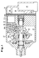
- variable displacement swash plate compressor according to one embodiment of the present invention will now be described with reference to Figs. 1-4.
- the swash plate compressor includes a cylinder block 11, a front housing member 12 coupled to the front of the cylinder block 11, and a rear housing member 14 coupled to the rear of the cylinder block 11.
- the front housing member 12, the cylinder block 11, and the rear housing member 14 form the compressor housing.
- a crank chamber 15 is defined between the front housing member 12 and the cylinder block 11.
- a drive shaft 16 is supported by the front housing member 12 and the cylinder block 11.
- the drive shaft is driven by a vehicle engine (not shown).
- a lug plate 18 is fixed to the drive shaft 16 in the crank chamber 15.
- a support plate 21 is located in the crank chamber 15. The drive shaft 16 passes through a central hole 22 of the support plate 21.
- a pair of support arms 27 are formed on the rear surface of the lug plate 18.
- a guide hole 27a is formed in the distal end of each support arm 27.
- Two guide pins 28, which are formed on the front surface of the support plate 21, include spherical portions 28a at their distal ends, respectively. The spherical portions 28a of the guide pins 28 are received in the corresponding guide holes 27a of the support arms 27.
- the support plate 21 integrally rotates with the drive shaft 16 through the guide pins 28 and the support arms 27.
- the support plate 21 is supported by the drive shaft 16 and slides axially and inclines with respect to the axis L of the drive shaft 16.
- a boss 29 is formed on the rear surface of the support plate 21 about the axis S of the support plate 21.
- An annular positioning surface 23 is formed on the support plate 21 as shown in figs 1 and 2. The diameter of the positioning surface 23 is greater than that of the boss 29.
- an angular ball bearing 32 which serves as a radial bearing, is located between the boss 29 and a swash plate 33.
- the ball bearing 32 includes an inner race 32a, an outer race 32b, and balls 32c.
- the inner race 32a is press-fitted to the boss 29.
- the balls 32c are located between the inner race 32a and the outer race 32b.
- the position of the inner race 32a is determined by the positioning surface 23 the rear surface of which contacts the inner race 32a.
- the flange-shaped swash plate 33 is located on the radially outer side of the outer race 32b.
- a thrust roller bearing 31 is located between the outer race 32b of the angular ball bearing 32 and the support plate 21.
- the thrust roller bearing 31 includes rollers 31c.
- the rollers 31c are located between a front contact surface 31a on the support plate 21, and a contact surface 31b on the outer race 32b of the angular ball bearing 32.
- the front contact surface 31a is located on an annular rear surface of the support plate 21 and is radially outward of the positioning surface 23.
- the rear contact surface 31b is located on an annular front surface of the outer race 32b.
- the rollers 31c roll directly on the support plate 21 and the outer race 32b.
- Cylinder bores 11a are formed in the cylinder block 11.
- a suction chamber 38 and a discharge chamber 39 are formed in the rear housing member 14.
- Each single-headed piston 35 is accommodated reciprocally in each bore 11a, and each piston 35 has a head 35a and a neck 35b.
- the head 35a of each piston 35 is located in the corresponding cylinder bore 11a.
- a recess 36 is formed in each neck 35b.
- Semi-spherical shoe seats 36a are formed in opposite surfaces of each recess 36.
- a pair of semi-spherical shoes 37 are received by the shoe seats 36a in each recess 36 such that each shoe 37 can slide with respect to the corresponding seat 36a.
- the periphery of the swash plate 33 is received between the shoes 37 in each recess 36.
- the surfaces of the swash plate 33 that contact the shoes 37 are plated with tin or coated with molybdenum disulfide to reduce friction.
- the support plate 21 When an external drive source rotates the drive shaft 16, the support plate 21 is rotated by the lug plate 18.
- the axis S of the support plate 21 is inclined with respect to the axis L of the drive shaft 16. Accordingly, a point on the support plate 21 moves rearward and frontward with respect to the cylinder block 11 when the support plate 21 rotates, and this motion is converted into reciprocation of the pistons 35 through the swash plate 33 and the shoes 37.
- the reciprocation of the pistons 35 repeats a cycle of drawing refrigerant gas into the cylinder bores 11a, compressing the refrigerant gas, and discharging the refrigerant gas to the discharge chamber 39.
- the support plate 21 rotates relative to the swash plate 33 (or the outer race 32b), and the friction between the swash plate 33 and the shoes 37 prevents the swash plate 33 from being rotated by the support plate 21.
- the inclination angle of the axis S of the support plate 21 with respect to the axis L of the drive shaft 16 is varied by varying the pressure in the crank chamber 15 with a control valve 40. This varies the stroke of the pistons 35 and adjusts the compressor displacement.
- Friction occurs between the swash plate 33 and the shoes 37. This substantially prevents the swash plate 33 from being rotated by the support plate 21. However, even if the swash plate 33 is rotated by the support plate 21, the relative rotation speed between the swash plate 33 and the shoes 37 is slow, which limits power losses and extends the life of the compressor, compared with a compressor in which swash plate and shoes in high speed.
- the swash plate 33 is integrally formed with the outer race 32b and coupled to the pistons 35 through the shoes 37, which simplifies the shape of the swash plate 33.
- the swash plate is flat and annular.
- the outer race 32b of the angular ball bearing 32 is integrally formed with the swash plate without difficulty. That is, the outer race 32b and the swash plate 33 are formed by cutting a flat annular metal plate.
- X represents the diameter of the rollers 31 of the thrust bearing 31.
- Y represents the distance between the rolling surfaces 31a, 31b before the rollers 31c are assembled in a state that the inner race 32a contacts the positioning surface 23 assumed there are no clearances in the radial bearing 32 in the thrust direction (shown by the solid line of Fig.4).
- Z represents the maximum offset amount of the outer race 32b from the inner race 32a (shown by the broken lines of Fig. 4 in an exaggerated manner).
- the expression (1) is satisfied when X is greater than Y. That is, if X is greater than Y when the rollers 31c are located between the contact surfaces 31a and 31b, the distance between the contact surfaces 31a and 31b is extended to X. Therefore, the outer race 32b moves rearward along the axis S relative to the inner race 32a by a distance represented by X minus Y.
- the expression (1) can be satisfied when X is less than Y. If the rollers 31c are located between the contact surfaces 31a, 31b when X is less than Y, there is some clearance between the rollers 31c and the contact surfaces 31a, 31b. However, when the compressor is operating, a compression load is applied to the swash plate 33 through the pistons 35, which moves the outer race 32b toward the contact surface 31a on the support plate 21. Therefore, the rollers 31c are firmly received between the contact surfaces 31a, 31b.
- the outer race 32b is permitted to move toward the support plate 21 by a distance represented by Y minus X. Accordingly, the rollers 31c are firmly received between the contact surfaces 31a, 31b, and the thrust roller bearing 31 receives the compression load applied to the swash plate 33.
- the present embodiment has the following advantages.
- the swash plate 33 is integrally formed with the outer race 32b of the angular ball bearing 32.
- the contact surfaces 31a, 31b, which serve as races for the thrust roller bearing 31, are directly formed on the support plate 21 and the outer race 32b of the thrust roller bearing 31, respectively. This reduces the number of parts and manufacturing costs.
- the present invention can further be embodied as follows.
- a radial roller bearing may be used instead of the angular ball bearing 32.
- the present invention may be embodied to the other types of swash plate compressors, such as, fixed displacement type, double head piston type.
- a compressor has a housing and a cylinder bore (11a).
- a piston (35) is accommodated in the cylinder bore (11a).
- a drive shaft (16) is supported by the housing.
- An annular support plate (21) is driven by the drive shaft (16).
- the support plate (21) surrounds the drive shaft (16) and inclines with respect to the axis of the drive shaft (16).
- the support plate (21) has an boss (29).
- the radial bearing (32) has an outer race (32b).
- a disk-like swash plate (33) is formed integrally with the outer race (32b). The swash plate (33) is connected the piston (35) to cause the piston (35) to reciprocate.
Abstract
Description
Claims (5)
- A compressor comprising:a housing;a cylinder bore (11a) formed in the housing;a piston (35) accommodated in the cylinder bore (11a);a drive shaft (16) rotatably supported by the housing;an support plate (21) integrally driven with the drive shaft (16), wherein the drive shaft (16) extends through the support plate (21), wherein the support plate (21) inclines with respect to the axis of the drive shaft (16), wherein the support plate (21) has an axially projecting boss (29), the compressor being characterized by:a radial bearing (32) located about the boss (29), wherein the radial bearing (32) has an outer race (32b);a disk-like swash plate (33) formed integrally with the outer race (32b), wherein the swash plate (33) is connected the piston (35) to cause the piston (35) to reciprocate.
- The compressor according to claim 1, characterized in that a thrust bearing (31) is located between the outer race (32a) of the radial bearing (32) and the support plate (21).
- The compressor according to claim 2, characterized in that the thrust bearing (31) is a thrust roller bearing, wherein the thrust roller bearing (31) has rollers (31c), wherein the outer race (32a) of the radial bearing has a contact surface (31b) on which the rollers (31c) of the radial bearing roll.
- The compressor according to claim 3, characterized in that the radial bearing (32) has an inner race (32a) fitted to the boss (29), wherein the support plate (21) has a positioning surface (23) to contact the inner race (32b) such that the positioning surface (23) limits axial movement of the inner race (32a) in one direction, and the contact surface functions as a rear contact surface (31b), and a front contact surface (31a) is formed on the support plate (21) to face the rear contact surface (31b), wherein the rollers (31c) of the thrust roller bearing (31) are located between the front contact surface (31a) and the rear contact surface (31b), wherein when X represents the diameter of the roller of the thrust bearing (31), and Y represents the distance between the front and the rear contact surfaces (31a, 31b) before the roller (31c) is assembled with the inner race (32b) contacting the positioning surface (23), assuming there is no slack in the radial bearing (32) in the thrust direction, and Z represents a maximum allowance offset amount, in the axial direction, of the outer race (32b) from the inner race (32a), the following equation is satisfied:
- A radial bearing (32) used in a compressor, wherein the compressor has an annular support plate (21) integrally driven with a drive shaft (16) and a piston (35) accommodated in a cylinder bore (11a), wherein the support plate (21) has an axially projecting boss (29), wherein the drive shaft (16) extends through the support plate (21), the radial bearing comprising being characterized by:an inner race (32a) fixed to the boss (29);an outer race (32b);a plurality of balls (31c) located between the inner race (32a) and the outer race (32b); anda disk-like swash plate (33) integrally formed with the outer race (32b), wherein the swash plate (33) is connected the piston (35) to reciprocate the piston (35).
Applications Claiming Priority (2)
| Application Number | Priority Date | Filing Date | Title |
|---|---|---|---|
| JP12979699 | 1999-05-11 | ||
| JP11129796A JP2000320455A (en) | 1999-05-11 | 1999-05-11 | Swash plate type compressor and radial rolling bearing |
Publications (2)
| Publication Number | Publication Date |
|---|---|
| EP1052403A2 true EP1052403A2 (en) | 2000-11-15 |
| EP1052403A3 EP1052403A3 (en) | 2001-04-25 |
Family
ID=15018452
Family Applications (1)
| Application Number | Title | Priority Date | Filing Date |
|---|---|---|---|
| EP00109926A Withdrawn EP1052403A3 (en) | 1999-05-11 | 2000-05-10 | Bearing for swash plate compressor |
Country Status (3)
| Country | Link |
|---|---|
| US (1) | US6446540B1 (en) |
| EP (1) | EP1052403A3 (en) |
| JP (1) | JP2000320455A (en) |
Cited By (4)
| Publication number | Priority date | Publication date | Assignee | Title |
|---|---|---|---|---|
| EP1281864A1 (en) * | 2001-08-03 | 2003-02-05 | Zexel Valeo Climate Control Corporation | A wobble plate arrangement for a compressor |
| EP1363022A1 (en) * | 2002-05-10 | 2003-11-19 | Zexel Valeo Compressor Europe Gmbh | A wobble plate arrangement for a compressor |
| DE10250649A1 (en) * | 2002-10-30 | 2004-05-13 | Zexel Valeo Compressor Europe Gmbh | Axial piston compressor has supporting of swashplate provided by ring bearing which acts axially and radially at same time, with effective bearing planes of ring bearing crossing in relation to one another |
| DE102004056929A1 (en) * | 2004-11-25 | 2006-06-01 | Schaeffler Kg | Storage unit e.g. swash plate storage, producing method for e.g. piston compressor, involves mounting storage components on base plate and fixing components by caulking |
Families Citing this family (3)
| Publication number | Priority date | Publication date | Assignee | Title |
|---|---|---|---|---|
| US6990889B2 (en) * | 2003-12-16 | 2006-01-31 | Rix Industries | Swash plate drive system |
| JP2006112380A (en) * | 2004-10-18 | 2006-04-27 | Jtekt Corp | Bearing device for swash plate type compressor |
| CN102691722B (en) * | 2012-04-11 | 2017-11-03 | 上海齐耀动力技术有限公司 | A kind of two degrees of freedom rolling bearing |
Citations (1)
| Publication number | Priority date | Publication date | Assignee | Title |
|---|---|---|---|---|
| JPH10196525A (en) | 1997-01-09 | 1998-07-31 | Sanden Corp | Swash plate compressor |
Family Cites Families (12)
| Publication number | Priority date | Publication date | Assignee | Title |
|---|---|---|---|---|
| US2241046A (en) * | 1938-02-07 | 1941-05-06 | Gunnar A Wahlmark | Fluid motor |
| JP2555026B2 (en) * | 1986-05-23 | 1996-11-20 | 株式会社日立製作所 | Variable capacity compressor |
| AU603867B2 (en) | 1987-02-19 | 1990-11-29 | Sanden Corporation | Wobble plate type compressor with variable displacement mechanism |
| JPH01182580A (en) * | 1988-01-13 | 1989-07-20 | Sanden Corp | Variable displacement oscillating compressor |
| JPH03141877A (en) | 1989-10-25 | 1991-06-17 | Hitachi Ltd | Compressor with swash plate |
| JP3026518B2 (en) * | 1991-07-03 | 2000-03-27 | サンデン株式会社 | Variable capacity rocking plate compressor |
| JP3276387B2 (en) | 1992-01-23 | 2002-04-22 | 株式会社デンソー | Swash plate type compressor |
| JP3197759B2 (en) * | 1994-08-22 | 2001-08-13 | 株式会社ゼクセルヴァレオクライメートコントロール | Full stroke positioning structure of variable displacement compressor |
| US5555626A (en) | 1995-11-27 | 1996-09-17 | S-B Power Tool Company | Reciprocating drive mechanism |
| JPH10159723A (en) | 1996-11-26 | 1998-06-16 | Nippon Soken Inc | Swash plate compressor |
| JPH1182296A (en) * | 1997-09-05 | 1999-03-26 | Sanden Corp | Variable delivery compressor |
| JP3141877B2 (en) | 1999-07-21 | 2001-03-07 | 株式会社日立製作所 | Packet switching system |
-
1999
- 1999-05-11 JP JP11129796A patent/JP2000320455A/en active Pending
-
2000
- 2000-05-09 US US09/568,296 patent/US6446540B1/en not_active Expired - Fee Related
- 2000-05-10 EP EP00109926A patent/EP1052403A3/en not_active Withdrawn
Patent Citations (1)
| Publication number | Priority date | Publication date | Assignee | Title |
|---|---|---|---|---|
| JPH10196525A (en) | 1997-01-09 | 1998-07-31 | Sanden Corp | Swash plate compressor |
Cited By (5)
| Publication number | Priority date | Publication date | Assignee | Title |
|---|---|---|---|---|
| EP1281864A1 (en) * | 2001-08-03 | 2003-02-05 | Zexel Valeo Climate Control Corporation | A wobble plate arrangement for a compressor |
| EP1363022A1 (en) * | 2002-05-10 | 2003-11-19 | Zexel Valeo Compressor Europe Gmbh | A wobble plate arrangement for a compressor |
| DE10250649A1 (en) * | 2002-10-30 | 2004-05-13 | Zexel Valeo Compressor Europe Gmbh | Axial piston compressor has supporting of swashplate provided by ring bearing which acts axially and radially at same time, with effective bearing planes of ring bearing crossing in relation to one another |
| DE102004056929A1 (en) * | 2004-11-25 | 2006-06-01 | Schaeffler Kg | Storage unit e.g. swash plate storage, producing method for e.g. piston compressor, involves mounting storage components on base plate and fixing components by caulking |
| DE102004056929B4 (en) * | 2004-11-25 | 2014-11-27 | Schaeffler Technologies Gmbh & Co. Kg | Method for producing a storage unit |
Also Published As
| Publication number | Publication date |
|---|---|
| US6446540B1 (en) | 2002-09-10 |
| EP1052403A3 (en) | 2001-04-25 |
| JP2000320455A (en) | 2000-11-21 |
Similar Documents
| Publication | Publication Date | Title |
|---|---|---|
| EP0780572B1 (en) | Swash-plate type compressor | |
| US5540559A (en) | Variable capacity swash-plate type compressor | |
| US4712982A (en) | Variable displacement wobble plate type compressor with guide means for wobble plate | |
| US5785503A (en) | Variable displacement compressor | |
| EP1281866A2 (en) | Vibration damping mechanism for piston type compressor | |
| US6446540B1 (en) | Bearing for swash plate compressor | |
| US7406912B2 (en) | Swash plate compressor | |
| US6544004B2 (en) | Single-headed piston type compressor | |
| US20040055456A1 (en) | Variable displacement compressor | |
| JP2001289159A (en) | Variable displacement swash plate compressor | |
| JP2001107850A (en) | Swash plate type refrigerant compressor | |
| US6212995B1 (en) | Variable-displacement inclined plate compressor | |
| US5882179A (en) | Compressor with bearing between the drive shaft and the swash-plate boss | |
| EP0510496A1 (en) | Slant plate type compressor with variable displacement mechanism | |
| JP2001295755A (en) | Guide pin of variable displacement compressor and variable displacement compressor | |
| JPH10176655A (en) | Variable-displacement swash plate type compressor | |
| EP1693567A1 (en) | Swash plate-type compressor | |
| JP3272962B2 (en) | Variable displacement compressor | |
| EP1067288A2 (en) | Thrust bearing for the swash plate of a compressor | |
| EP1531266B1 (en) | Variable displacement compressor | |
| US7168359B2 (en) | Swash plate compressor | |
| JP4314405B2 (en) | Variable capacity swash plate compressor | |
| JP2990832B2 (en) | Swash plate compressor | |
| US20010042438A1 (en) | Piston for swash plate type compressor | |
| JP3048090B2 (en) | Variable capacity swash plate compressor |
Legal Events
| Date | Code | Title | Description |
|---|---|---|---|
| PUAI | Public reference made under article 153(3) epc to a published international application that has entered the european phase |
Free format text: ORIGINAL CODE: 0009012 |
|
| 17P | Request for examination filed |
Effective date: 20000510 |
|
| AK | Designated contracting states |
Kind code of ref document: A2 Designated state(s): DE FR IT |
|
| AX | Request for extension of the european patent |
Free format text: AL;LT;LV;MK;RO;SI |
|
| PUAL | Search report despatched |
Free format text: ORIGINAL CODE: 0009013 |
|
| AK | Designated contracting states |
Kind code of ref document: A3 Designated state(s): AT BE CH CY DE DK ES FI FR GB GR IE IT LI LU MC NL PT SE |
|
| AX | Request for extension of the european patent |
Free format text: AL;LT;LV;MK;RO;SI |
|
| RAP1 | Party data changed (applicant data changed or rights of an application transferred) |
Owner name: KABUSHIKI KAISHA TOYOTA JIDOSHOKKI |
|
| AKX | Designation fees paid |
Free format text: DE FR IT |
|
| 17Q | First examination report despatched |
Effective date: 20050415 |
|
| STAA | Information on the status of an ep patent application or granted ep patent |
Free format text: STATUS: THE APPLICATION IS DEEMED TO BE WITHDRAWN |
|
| 18D | Application deemed to be withdrawn |
Effective date: 20050826 |