EP1033577A2 - Test piece holder and apparatus for removing analyte excess incorporating the same - Google Patents
Test piece holder and apparatus for removing analyte excess incorporating the same Download PDFInfo
- Publication number
- EP1033577A2 EP1033577A2 EP00301778A EP00301778A EP1033577A2 EP 1033577 A2 EP1033577 A2 EP 1033577A2 EP 00301778 A EP00301778 A EP 00301778A EP 00301778 A EP00301778 A EP 00301778A EP 1033577 A2 EP1033577 A2 EP 1033577A2
- Authority
- EP
- European Patent Office
- Prior art keywords
- test piece
- piece holder
- capillary
- capillary grooves
- excess
- Prior art date
- Legal status (The legal status is an assumption and is not a legal conclusion. Google has not performed a legal analysis and makes no representation as to the accuracy of the status listed.)
- Granted
Links
Images


Classifications
-
- G—PHYSICS
- G01—MEASURING; TESTING
- G01N—INVESTIGATING OR ANALYSING MATERIALS BY DETERMINING THEIR CHEMICAL OR PHYSICAL PROPERTIES
- G01N35/00—Automatic analysis not limited to methods or materials provided for in any single one of groups G01N1/00 - G01N33/00; Handling materials therefor
- G01N35/00029—Automatic analysis not limited to methods or materials provided for in any single one of groups G01N1/00 - G01N33/00; Handling materials therefor provided with flat sample substrates, e.g. slides
- G01N2035/00099—Characterised by type of test elements
- G01N2035/00108—Test strips, e.g. paper
- G01N2035/00118—Test strips, e.g. paper for multiple tests
-
- G—PHYSICS
- G01—MEASURING; TESTING
- G01N—INVESTIGATING OR ANALYSING MATERIALS BY DETERMINING THEIR CHEMICAL OR PHYSICAL PROPERTIES
- G01N35/00—Automatic analysis not limited to methods or materials provided for in any single one of groups G01N1/00 - G01N33/00; Handling materials therefor
- G01N35/00029—Automatic analysis not limited to methods or materials provided for in any single one of groups G01N1/00 - G01N33/00; Handling materials therefor provided with flat sample substrates, e.g. slides
- G01N2035/00099—Characterised by type of test elements
- G01N2035/00108—Test strips, e.g. paper
- G01N2035/00128—Test strips, e.g. paper with pressing or squeezing devices
Definitions
- This invention relates generally to analysis of a liquid analyte using a test piece. More particularly, it relates to a test piece holder which is capable of removing an analyte excess. It also relates to an analyte excess removing device incorporating such a test piece holder.
- test piece In urine analysis, use is typically made of a strip-like test piece which carries a series of chemical pads each. For analysis, the test piece is immersed in an urine analyte for reaction with the chemical pads to determine, for example, the concentration of glucose, protein, occult blood or ketone body contained in an urine analyte, or the pH of the analyte, respectively.
- a known automatic or semi-automatic urine test apparatus utilizing such an analysis process includes a test piece holder for placing a test piece (which has been previously immersed in an urine analyte), and a transfer mechanism for moving the test piece holder together with the test piece to a measurement position where the chemical pads are successively detected by an optical sensor for determining the degree of color reaction at the pads.
- a transfer mechanism for moving the test piece holder together with the test piece to a measurement position where the chemical pads are successively detected by an optical sensor for determining the degree of color reaction at the pads.
- the speed of reaction at a relevant chemical pad is influenced by the amount of urine deposited or absorbed by that pad.
- the measurement of urine glucose concentration is greatly affected by the amount of urine excess because supply of oxygen needed for color reaction is blocked by the water content of the urine excess.
- a prior art analyte excess removing device designated by reference sign (a) includes a test piece holder (b) which is designed to have a pump-sucking function. More specifically, the test piece holder (b) has a top surface provided with an elongate holding groove (c) which is defined by a bottom wall (ci) corresponding in configuration to a test piece (S) for reception thereof, and a pair of ridges (c2) each rising from a respective longitudinal edge of the bottom wall (c 1 ). Each of the ridges (c2) serves to guide the test piece (S) into the holding groove (c) while preventing lateral deviation of the test piece (S).
- the bottom wall (c 1 ) of the holding groove (c) is penetrated by a plurality of pores (d) each of which is connected to a flexible tube (e) which is, in turn, connected to a suction pump (not shown).
- the prior art analyte excess removing device (a) described above requires a suction pump and its related accessories such as flexible tubes (e) for excess removal, which results in added cost. Further, the suction pump and the flexible tubes (e) must be washed periodically, so that maintenance of these components is not considered easy.
- test piece holder which is capable of removing an analyte excess with relying on a suction pump and its related accessories.
- Another object of the present invention is provide an analyte excess removing device which incorporates such a test piece holder.
- a test piece holder comprising an elongate top surface, and a pair of side surfaces located below the top surface, the top surface being provided with a test piece holding groove defined by an elongate bottom wall and a pair of ridges each rising from a respective longitudinal edge of the bottom wall, characterized that each of the ridges is formed with a plurality of upper capillary grooves extending vertically to open into the test piece holding groove, the bottom wall being formed with a plurality of capillary pores in corresponding relationship to and in communication with the upper capillary grooves, the capillary pores being open toward a respective one of the side surfaces.
- test piece holder structured as above will be specifically described hereinafter on the basis of a preferred embodiment.
- each of the side surfaces may be formed with a plurality of lower capillary grooves in corresponding relationship to and in communication with the upper capillary grooves and the capillary pores.
- the upper capillary grooves, the capillary pores and the lower capillary grooves, respectively may be arranged in a row at a constant interval.
- the upper capillary grooves, the capillary pores and the lower capillary grooves may be equal in width.
- the width of the upper capillary grooves, the capillary pores and the lower capillary grooves may be 0.4-1.0 mm, particularly 0.6-0.8 mm.
- each of the upper capillary grooves may have a depth which is larger than its width.
- each of the lower capillary grooves may have a depth which is larger than its width.
- each of the upper capillary grooves may penetrate horizontally through a respective one of the ridges.
- each of the side surfaces may be configured to taper downward.
- a test piece holder comprising an elongate top surface, and a pair of side surfaces located below the top surface, the top surface being provided with a test piece holding groove defined by an elongate bottom wall and a pair of ridges each rising from a respective longitudinal edge of the bottom wall, characterized that the bottom wall is formed with a plurality of capillary pores communicating with the test piece holding groove, each of the side surfaces being formed with a plurality of lower capillary grooves in corresponding relationship to and in communication with the capillary pores.
- an analyte excess removing device comprising the test piece holder as defined above, and a receptacle for receiving the test piece holder with the test piece holding groove exposed upwardly.
- the receptacle may have a bottom discharge opening for effectively discharging the analyte excess which collects at the bottom of the receptacle.
- the receptacle tapers downward when each side surface of the test piece holder also tapers downward.
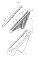
- Fig. 1 is a perspective view, in an exploded state, of an analyte excess removing device embodying the present invention.
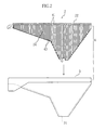
- Fig. 2 is an exploded side view of the same excess removing device.
- Fig. 3 is a plan view showing the same excess removing device.
- Fig. 4 is an enlarged fragmentary plan view showing the same excess removing device.
- Fig. 5 is a sectional view taken along lines V-V in Fig. 4.
- Fig. 6 is a sectional view taken along lines VI-VI in Fig. 4.
- Fig. 7 is a schematic side view showing a test apparatus incorporating the excess removing device.
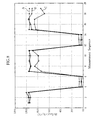
- Fig. 8 is a graph showing comparison in excess removing ability between the analyte excess removing device of the present invention and that of the prior art.
- Fig. 9 is a sectional view showing a prior art suction type excess removing device.
- an analyte excess removing device embodying the present invention is generally designated by reference numeral 1 (see Figs. 1 and 2).
- the analyte excess removing device 1 comprises a test piece holder 2 and a receptacle 3 in which the holder 2 is received.
- the test piece holder 2 is a shaped plate which has a top surface provided with a holding groove 20.
- the test piece holder 2 may be formed by molding ABS resin for example.
- the test piece holder 2 is received in the receptacle 3 in such a manner that the holding groove 20 is upwardly exposed.
- a test piece S comprises a strip S b made of a plastic material.
- the strip S b has an upper surface carrying a series of chemical pads s 1 -s 8 each for determining, forexample, the concentration of glucose, protein, occult blood or ketone body contained in an urine analyte, or the pH of the analyte, respectively.
- the holding groove 20 of the test piece holder 2 is configured to suitably receive the test piece S. More specifically, as shown in Figs. 1, 4 and 6, the holding groove 20 is defined by a bottom wall 21 corresponding in configuration to the test piece S, and a pair of ridges 22 each rising from a respective longitudinal edge of the bottom wall 21. In the illustrated embodiment, each of the ridges 22 is inclined toward the bottom wall 21 for gravitationally guiding the test piece S into the holding groove 20 (see Figs. 5 and 6).
- Each ridge 22 is formed with a plurality of upper capillary grooves 41 which extend vertically to the bottom wall 21 of the holding groove 20, as shown in Figs. 3-5.
- the upper capillary grooves 41 are spaced from each other at a constant interval.
- the width of the upper capillary grooves 41 may be 0.4-1.0 mm, preferably 0.6-0.8 mm, for example. If the groove width is smaller than 0.4 mm, difficulty arises in forming the upper capillary grooves 41 by molding. If the groove width is larger than 1.0 mm, the upper capillary grooves 41 may fail to provide a sufficient capillary action needed for sucking an excess of the analyte.
- each upper capillary groove 41 The interval between the upper capillary grooves 41 is constant and may be rendered as small as possible, provided that the molding of the test piece holder 2 can be performed without problem.
- the depth of each upper capillary groove 41 should be preferably larger than the width of that groove for increasing the amount of the analyte excess sucked per groove.
- each upper capillary groove 41 penetrates horizontally or laterally through the ridge 22 for increasing the capacity of sucking the analyte excess.
- the bottom wall 21 of the holding groove 20 is provided with a plurality of capillary pores 42 in corresponding relationship to the upper capillary grooves 41 for communicating therewith. These capillary pores 42 penetrate vertically through the bottom wall 21 and correspond in width to the upper capillary grooves 41.
- the test piece holder 2 has, under the holding groove 20, a pair of side surfaces 24 each of which is formed with lower capillary grooves 43 in corresponding relationship to the upper capillary grooves 41 and the capillary pores 42.
- the lower capillary grooves 43 extend vertically downward from the bottom wall 21 of the holding groove 20 in communication with the upper capillary grooves 41 through the capillary pores 42.
- the lower capillary grooves 43 correspond in width to the upper capillary grooves 41 and the capillary pores 42.
- the depth of the lower capillary grooves 43 which is larger than their width, may be suitably determined in consideration of technical feasibility of molding the test piece holder 2.
- the test piece holder 2 is shaped to taper downward.
- the receptacle 3 for receiving the test piece holder 2 is correspondingly configured. More specifically, the receptacle 3 is a container which is open upwardly and which tapers downward in corresponding relationship to the test piece holder 2 for snugly receiving the latter.
- the bottom tapering end of the receptacle 3 is formed with a discharge opening 31 for discharging the analyte excess sucked downward by capillary action, as described hereinafter.
- the receptacle 3 may be made of ABS resin, for example, by molding.
- the analyte excess removing device 1 including the test piece holder 2 and the receptacle 3 is mounted at a transfer mechanism 51 of an urine test apparatus 5, as schematically illustrated in Fig. 7.
- the transfer mechanism 51 reciprocates between a standby position outside the housing of the test apparatus 5 and a measuring position inside the housing. At the standby position (indicated by solid lines in Fig. 7), the holding groove 20 of the test piece holder 2 is exposed for replacing an analyzed test piece with a new one.
- the test apparatus 5 is internally provided with an optical sensor 52 for optically detecting the degree of color reaction at the respective chemical pads s 1 -s 8 of the test piece S.
- the chemical pads s 1 -s 8 successively pass under the optical sensor 52.
- the analyte excess removing device 1 and the urine test apparatus 5 incorporating it operate in the following manner.
- the transfer mechanism 51 of the urine test apparatus 5 causes the analyte excess removing device 1 or the test piece holder 2 to assume the standby position.
- a test piece S which has been previously immersed in an urine analyte is placed in the holding groove 20 of the test piece holder 2 with a predetermined timing.
- Such placement of the test piece may be performed manually or automatically by a loader (not shown).
- the inclined guide surfaces 22a of the respective ridges 22 serve to smoothly guide the test piece S into the holding groove.
- the test piece S When the test piece S is placed in the holding groove 20 of the test piece holder 2, it is wet with an excessive amount of urine than is necessary for causing intended color reaction at the respective chemical pads s1-s8.
- the upper capillary grooves 41 are formed at the respective ridges 22 to extend vertically, they suck the urine excess immediately by capillary action. The urine thus sucked falls down onto the side surfaces 24 of the test piece holder 2 through the capillary pores 42 which also provide additional capillary action for assisting suction of the urine excess.
- the lower capillary grooves 43 on the respective side surfaces 24 of the test piece holder 2 also provides capillary action for additionally assisting downward pull of the urine excess.
- the combination of the upper capillary grooves 21, the capillary pores 22 and the lower capillary grooves serves to rapidly remove the urine excess from the test piece S and the holding groove 20.
- the lower capillary grooves 43 are much longer than the upper capillary grooves 41 and the capillary pores 42, they can provide a large capacity for repetitively performing urine excess removal (i.e., urine test).
- the urine excess moving downward in the lower capillary groove ultimately collects at the tapered bottom end of the test piece holder 2 primarily due to capillary action and partially due to gravity after flowing along the tapering edges.
- the test piece holder 2 is received substantially entirely in the receptacle 3, it is possible to prevent the urine excess from scattering to contaminate the various portions of the test apparatus 5 while moving downward on the test piece holder.
- the urine excess thus collected at the tapered bottom end of the test piece holder 2 is discharged through the discharge opening 31 into a collecting pan (not shown) provided at the bottom of the test apparatus 5.
- test piece S held by the test piece holder 2 is moved progressively to the measurement position by the transfer mechanism 51. During such movement, the chemical pads s 1 -s 8 on the test piece S are successively subjected to detection by the optical sensor 52 for determination as to the degree of color reaction. After optical measurement, the test piece holder 2 is then moved to the standby position where the analyzed test piece S is replaced with a new one.
- the test piece holder 2 may be made of ABS resin by molding.
- the test piece holder 2 may be made of any resin, provided that the selected resin has good affinity with water for enhancing the capillary action of the upper capillary grooves 41, the capillary pores 42 and the lower capillary grooves 43.
- the selected resin may preferably contain a polymer component or components having a hydrophilic group or groups such as -OH, -SO 3 H, -COOH, -NH 2 and -CO.
- the receptacle 3 which may be also made of ABS resin as in the illustrated embodiment, does not need to have good affinity with water. For this reason, the receptacle 3 may be made of any other resin.
- Fig. 8 is a graph showing comparison in excess removing ability between the analyte excess removing device of the present invention and that of the prior art (Fig. 9).
- the graph of Fig. 8 is based on the results of tests wherein, for determination of urine glucose concentration, a series of low-concentration samples (negative samples) and a series of high-concentration samples (positive samples) were alternately analyzed.
- the curve A represents the results obtained for the overall series of 1st-19th samples when the analyte excess removing device 1 of the present invention was used for placing each test piece.
- the curve B represents the results obtained for the overall series of 1st-19th samples when the analyte excess removing device (a) of the prior (Fig. 9) was used for placing each test piece.
- the curve C represents the results obtained for the overall series of 1st-19th samples when the analyte excess removing device (a) of theprior art was used without applying pump (vacuum) suction.
- the curve C of the graph indicates that the results of glucose concentration measurement shift clearly to the positive side from the expected value when measurement was performed for a series of negative samples after performing measurement for a series of positive samples. This means that the excess of the positive samples remaining on the test piece holder gave adverse influences on the subsequent analysis of the negative samples. By contrast, no remarkable shift or deviation was observed with respect to the curves A and B even when measurement was performed for a series of negative samples after performing measurement for a series of positive samples. Thus, it can be concluded that the analyte excess removing device of the present invention is as effective as the prior art pumping type excess removing device and is therefore more advantageous than it in that no pump (i.e., energy consumption) is needed.
- Tables 1 and 2 represent the results of measurement of urine glucose concentration which were performed for respective sets of known-concentration samples, each set including 10 samples of a given glucose concentration (Omg/dl, 30mg/dl, 60mg/dl, 250mg/dl, 1,500mg/dl, respectively).
- Table 1 shows the results of concentration measurement (as determined by reflectivity) performedwith the use of the excess removing device 1 of the present invention
- Table 2 illustrates the results of concentration measurement performed with the use of the prior art excess removing device (a) illustrated in Fig. 9.
- the notation "S.D.” represents "Standard Deviation".
- the analyte excess removing device 1 (consisting of the test piece holder 2 and the receptacle) according to the illustrated embodiment is entirely made of a resin material and requires no suction pump or its related accessories.
- the analyte excess removing device 1 is economically advantageous.
- the test piece holder 2 and the receptacle 3 can be washed or flushed whole and therefore maintained very easily.
- the present invention may be applied to any kind of test piece holder for holding a test piece which is immersed in or impregnated with a liquid analyte (not limited to urine) for chemical reaction.
- a liquid analyte not limited to urine
Abstract
Description
- This invention relates generally to analysis of a liquid analyte using a test piece. More particularly, it relates to a test piece holder which is capable of removing an analyte excess. It also relates to an analyte excess removing device incorporating such a test piece holder.
- In urine analysis, use is typically made of a strip-like test piece which carries a series of chemical pads each. For analysis, the test piece is immersed in an urine analyte for reaction with the chemical pads to determine, for example, the concentration of glucose, protein, occult blood or ketone body contained in an urine analyte, or the pH of the analyte, respectively.
- Typically, a known automatic or semi-automatic urine test apparatus utilizing such an analysis process includes a test piece holder for placing a test piece (which has been previously immersed in an urine analyte), and a transfer mechanism for moving the test piece holder together with the test piece to a measurement position where the chemical pads are successively detected by an optical sensor for determining the degree of color reaction at the pads. When the test piece is placed on the test piece holder, it is necessary to remove an excess of the urine analyte for the following reasons.
- First, depending on an item of analysis, the speed of reaction at a relevant chemical pad is influenced by the amount of urine deposited or absorbed by that pad. In particular, the measurement of urine glucose concentration is greatly affected by the amount of urine excess because supply of oxygen needed for color reaction is blocked by the water content of the urine excess.
- Secondly, since a test piece carries a plurality of chemical pads, it is possible that a chemical substance or substances from each pad may dissolve in an urine excess and thereby contaminate other pads of the same test piece, thereby resulting in inaccurate measurement.
- In the third place, when analyzing a plurality of test pieces in succession with a same test piece holder, an urine excess remaining on the test piece holder after replacement of one test piece may contaminate the next test piece which is immersed with a different urine analyte. This also results in inaccurate analysis.
- For these reasons, the prior art automatic or semi-automatic urine test apparatus incorporates an analyte excess removing device. A typical example of such a device is illustrated in Fig. 9 of the accompanying drawings.
- As shown in Fig. 9, a prior art analyte excess removing device designated by reference sign (a) includes a test piece holder (b) which is designed to have a pump-sucking function. More specifically, the test piece holder (b) has a top surface provided with an elongate holding groove (c) which is defined by a bottom wall (ci) corresponding in configuration to a test piece (S) for reception thereof, and a pair of ridges (c2) each rising from a respective longitudinal edge of the bottom wall (c1). Each of the ridges (c2) serves to guide the test piece (S) into the holding groove (c) while preventing lateral deviation of the test piece (S). The bottom wall (c1) of the holding groove (c) is penetrated by a plurality of pores (d) each of which is connected to a flexible tube (e) which is, in turn, connected to a suction pump (not shown).
- In operation, as soon as a test piece (S) having been previously immersed in an urine analyte is placed in the holding groove (c), a suction force is applied to the holding groove by the suction pump through the flexible tube (e) and a respective one of the pores (d). Thus, an excess of the urine analyte is removed immediately under the positive suction.
- However, the prior art analyte excess removing device (a) described above requires a suction pump and its related accessories such as flexible tubes (e) for excess removal, which results in added cost. Further, the suction pump and the flexible tubes (e) must be washed periodically, so that maintenance of these components is not considered easy.
- It is, therefore, an object of the present invention to provide a test piece holder which is capable of removing an analyte excess with relying on a suction pump and its related accessories.
- Another object of the present invention is provide an analyte excess removing device which incorporates such a test piece holder.
- According to a first aspect of the present invention, there is provided a test piece holder comprising an elongate top surface, and a pair of side surfaces located below the top surface, the top surface being provided with a test piece holding groove defined by an elongate bottom wall and a pair of ridges each rising from a respective longitudinal edge of the bottom wall, characterized that each of the ridges is formed with a plurality of upper capillary grooves extending vertically to open into the test piece holding groove, the bottom wall being formed with a plurality of capillary pores in corresponding relationship to and in communication with the upper capillary grooves, the capillary pores being open toward a respective one of the side surfaces.
- The operating principles and technical advantages of the test piece holder structured as above will be specifically described hereinafter on the basis of a preferred embodiment.
- Preferably, each of the side surfaces may be formed with a plurality of lower capillary grooves in corresponding relationship to and in communication with the upper capillary grooves and the capillary pores. In this case, the upper capillary grooves, the capillary pores and the lower capillary grooves, respectively, may be arranged in a row at a constant interval. Further, the upper capillary grooves, the capillary pores and the lower capillary grooves may be equal in width.
- Preferably, the width of the upper capillary grooves, the capillary pores and the lower capillary grooves may be 0.4-1.0 mm, particularly 0.6-0.8 mm. Further, each of the upper capillary grooves may have a depth which is larger than its width. Similarly, each of the lower capillary grooves may have a depth which is larger than its width.
- Preferably, each of the upper capillary grooves may penetrate horizontally through a respective one of the ridges.
- Preferably, each of the side surfaces may be configured to taper downward.
- According to a second aspect of the present invention, there is provided a test piece holder comprising an elongate top surface, and a pair of side surfaces located below the top surface, the top surface being provided with a test piece holding groove defined by an elongate bottom wall and a pair of ridges each rising from a respective longitudinal edge of the bottom wall, characterized that the bottom wall is formed with a plurality of capillary pores communicating with the test piece holding groove, each of the side surfaces being formed with a plurality of lower capillary grooves in corresponding relationship to and in communication with the capillary pores.
- According to a third aspect of the present invention, there is provided an analyte excess removing device comprising the test piece holder as defined above, and a receptacle for receiving the test piece holder with the test piece holding groove exposed upwardly.
- Preferably, the receptacle may have a bottom discharge opening for effectively discharging the analyte excess which collects at the bottom of the receptacle.
- In a preferred embodiment, the receptacle tapers downward when each side surface of the test piece holder also tapers downward.
- Other objects, features and advantages of the present invention will become apparent from the following description of the preferred embodiment given with reference to the accompanying drawings.
- Fig. 1 is a perspective view, in an exploded state, of an analyte excess removing device embodying the present invention.
- Fig. 2 is an exploded side view of the same excess removing device.
- Fig. 3 is a plan view showing the same excess removing device.
- Fig. 4 is an enlarged fragmentary plan view showing the same excess removing device.
- Fig. 5 is a sectional view taken along lines V-V in Fig. 4.
- Fig. 6 is a sectional view taken along lines VI-VI in Fig. 4.
- Fig. 7 is a schematic side view showing a test apparatus incorporating the excess removing device.
- Fig. 8 is a graph showing comparison in excess removing ability between the analyte excess removing device of the present invention and that of the prior art.
- Fig. 9 is a sectional view showing a prior art suction type excess removing device.
- The preferred embodiment of the present invention will be specifically described with reference to the accompanying drawings.
- Referring to the drawings, an analyte excess removing device embodying the present invention is generally designated by reference numeral 1 (see Figs. 1 and 2). The analyte excess removing
device 1 comprises atest piece holder 2 and areceptacle 3 in which theholder 2 is received. - As better shown in Figs. 1 and 2, the
test piece holder 2 is a shaped plate which has a top surface provided with aholding groove 20. Thetest piece holder 2 may be formed by molding ABS resin for example. Thetest piece holder 2 is received in thereceptacle 3 in such a manner that theholding groove 20 is upwardly exposed. - As also shown in Fig. 1, a test piece S comprises a strip Sb made of a plastic material. The strip Sb has an upper surface carrying a series of chemical pads s1-s8 each for determining, forexample, the concentration of glucose, protein, occult blood or ketone body contained in an urine analyte, or the pH of the analyte, respectively.
- The
holding groove 20 of thetest piece holder 2 is configured to suitably receive the test piece S. More specifically, as shown in Figs. 1, 4 and 6, theholding groove 20 is defined by abottom wall 21 corresponding in configuration to the test piece S, and a pair ofridges 22 each rising from a respective longitudinal edge of thebottom wall 21. In the illustrated embodiment, each of theridges 22 is inclined toward thebottom wall 21 for gravitationally guiding the test piece S into the holding groove 20 (see Figs. 5 and 6). - Each
ridge 22 is formed with a plurality of uppercapillary grooves 41 which extend vertically to thebottom wall 21 of the holdinggroove 20, as shown in Figs. 3-5. In the illustrated embodiment, the uppercapillary grooves 41 are spaced from each other at a constant interval. The width of the uppercapillary grooves 41 may be 0.4-1.0 mm, preferably 0.6-0.8 mm, for example. If the groove width is smaller than 0.4 mm, difficulty arises in forming the uppercapillary grooves 41 by molding. If the groove width is larger than 1.0 mm, the uppercapillary grooves 41 may fail to provide a sufficient capillary action needed for sucking an excess of the analyte. The interval between the uppercapillary grooves 41 is constant and may be rendered as small as possible, provided that the molding of thetest piece holder 2 can be performed without problem. The depth of eachupper capillary groove 41 should be preferably larger than the width of that groove for increasing the amount of the analyte excess sucked per groove. In the illustrated embodiment, eachupper capillary groove 41 penetrates horizontally or laterally through theridge 22 for increasing the capacity of sucking the analyte excess. - As also shown in Figs. 3-5, the
bottom wall 21 of the holdinggroove 20 is provided with a plurality ofcapillary pores 42 in corresponding relationship to the uppercapillary grooves 41 for communicating therewith. Thesecapillary pores 42 penetrate vertically through thebottom wall 21 and correspond in width to the uppercapillary grooves 41. - Further, the
test piece holder 2 has, under the holdinggroove 20, a pair of side surfaces 24 each of which is formed with lowercapillary grooves 43 in corresponding relationship to the uppercapillary grooves 41 and the capillary pores 42. The lowercapillary grooves 43 extend vertically downward from thebottom wall 21 of the holdinggroove 20 in communication with the uppercapillary grooves 41 through the capillary pores 42. The lowercapillary grooves 43 correspond in width to the uppercapillary grooves 41 and the capillary pores 42. The depth of the lowercapillary grooves 43, which is larger than their width, may be suitably determined in consideration of technical feasibility of molding thetest piece holder 2. - Returning to Figs. 1 and 2, the
test piece holder 2 is shaped to taper downward. Thus, thereceptacle 3 for receiving thetest piece holder 2 is correspondingly configured. More specifically, thereceptacle 3 is a container which is open upwardly and which tapers downward in corresponding relationship to thetest piece holder 2 for snugly receiving the latter. The bottom tapering end of thereceptacle 3 is formed with adischarge opening 31 for discharging the analyte excess sucked downward by capillary action, as described hereinafter. Thereceptacle 3 may be made of ABS resin, for example, by molding. - The analyte
excess removing device 1 including thetest piece holder 2 and thereceptacle 3 is mounted at atransfer mechanism 51 of anurine test apparatus 5, as schematically illustrated in Fig. 7. Thetransfer mechanism 51 reciprocates between a standby position outside the housing of thetest apparatus 5 and a measuring position inside the housing. At the standby position (indicated by solid lines in Fig. 7), the holdinggroove 20 of thetest piece holder 2 is exposed for replacing an analyzed test piece with a new one. Thetest apparatus 5 is internally provided with anoptical sensor 52 for optically detecting the degree of color reaction at the respective chemical pads s1-s8 of the test piece S. Thus, while moving to the measuring position (indicated by phantom lines), the chemical pads s1-s8 successively pass under theoptical sensor 52. - The analyte
excess removing device 1 and theurine test apparatus 5 incorporating it operate in the following manner. - Initially, the
transfer mechanism 51 of theurine test apparatus 5 causes the analyteexcess removing device 1 or thetest piece holder 2 to assume the standby position. In this position, a test piece S which has been previously immersed in an urine analyte is placed in the holdinggroove 20 of thetest piece holder 2 with a predetermined timing. Such placement of the test piece may be performed manually or automatically by a loader (not shown). When the test piece S is placed in the holdinggroove 20, the inclined guide surfaces 22a of therespective ridges 22 serve to smoothly guide the test piece S into the holding groove. - When the test piece S is placed in the holding
groove 20 of thetest piece holder 2, it is wet with an excessive amount of urine than is necessary for causing intended color reaction at the respective chemical pads s1-s8. However, since the uppercapillary grooves 41 are formed at therespective ridges 22 to extend vertically, they suck the urine excess immediately by capillary action. The urine thus sucked falls down onto the side surfaces 24 of thetest piece holder 2 through the capillary pores 42 which also provide additional capillary action for assisting suction of the urine excess. Further, the lowercapillary grooves 43 on the respective side surfaces 24 of thetest piece holder 2 also provides capillary action for additionally assisting downward pull of the urine excess. Thus, the combination of the uppercapillary grooves 21, the capillary pores 22 and the lower capillary grooves serves to rapidly remove the urine excess from the test piece S and the holdinggroove 20. Moreover, since the lowercapillary grooves 43 are much longer than the uppercapillary grooves 41 and the capillary pores 42, they can provide a large capacity for repetitively performing urine excess removal (i.e., urine test). - The urine excess moving downward in the lower capillary groove ultimately collects at the tapered bottom end of the
test piece holder 2 primarily due to capillary action and partially due to gravity after flowing along the tapering edges. However, since thetest piece holder 2 is received substantially entirely in thereceptacle 3, it is possible to prevent the urine excess from scattering to contaminate the various portions of thetest apparatus 5 while moving downward on the test piece holder. The urine excess thus collected at the tapered bottom end of thetest piece holder 2 is discharged through thedischarge opening 31 into a collecting pan (not shown) provided at the bottom of thetest apparatus 5. - After removal of the urine excess upon lapse of a predetermined time, the test piece S held by the
test piece holder 2 is moved progressively to the measurement position by thetransfer mechanism 51. During such movement, the chemical pads s1-s8 on the test piece S are successively subjected to detection by theoptical sensor 52 for determination as to the degree of color reaction. After optical measurement, thetest piece holder 2 is then moved to the standby position where the analyzed test piece S is replaced with a new one. - In this way, the urine excess present on the test piece S and in the holding
groove 20 is effectively removed in a relatively short time. Thus, it is possible to prevent each chemical pad s1-s8 from being contaminated by a chemical substance or substances which may dissolve from any other pad in the urine excess. Further, after replacement of the analyzed test piece S with a new one, it is also possible to prevent or restrain the new test piece from being contaminated by the urine excess of the previous test piece remaining in the holdinggroove 20. - As previously described, the
test piece holder 2 may be made of ABS resin by molding. In practice, thetest piece holder 2 may be made of any resin, provided that the selected resin has good affinity with water for enhancing the capillary action of the uppercapillary grooves 41, the capillary pores 42 and the lowercapillary grooves 43. For this reason, the selected resin may preferably contain a polymer component or components having a hydrophilic group or groups such as -OH, -SO3H, -COOH, -NH2 and -CO. - On the other hand, the
receptacle 3, which may be also made of ABS resin as in the illustrated embodiment, does not need to have good affinity with water. For this reason, thereceptacle 3 may be made of any other resin. - Fig. 8 is a graph showing comparison in excess removing ability between the analyte excess removing device of the present invention and that of the prior art (Fig. 9). The graph of Fig. 8 is based on the results of tests wherein, for determination of urine glucose concentration, a series of low-concentration samples (negative samples) and a series of high-concentration samples (positive samples) were alternately analyzed. More specifically, in the tests, analysis was performed first for a sub-series of negative samples (1st-3rd samples), then for a sub-series of positive samples (4th-6th samples), again for another sub-series of negative samples (7th-11th samples), again for another sub-series of positive samples (12th-14th samples), and finally for a further sub-series of negative samples (15th-19th samples).
- In the graph of Fig. 8, the curve A represents the results obtained for the overall series of 1st-19th samples when the analyte
excess removing device 1 of the present invention was used for placing each test piece. The curve B represents the results obtained for the overall series of 1st-19th samples when the analyte excess removing device (a) of the prior (Fig. 9) was used for placing each test piece. The curve C represents the results obtained for the overall series of 1st-19th samples when the analyte excess removing device (a) of theprior art was used without applying pump (vacuum) suction. - The curve C of the graph indicates that the results of glucose concentration measurement shift clearly to the positive side from the expected value when measurement was performed for a series of negative samples after performing measurement for a series of positive samples. This means that the excess of the positive samples remaining on the test piece holder gave adverse influences on the subsequent analysis of the negative samples. By contrast, no remarkable shift or deviation was observed with respect to the curves A and B even when measurement was performed for a series of negative samples after performing measurement for a series of positive samples. Thus, it can be concluded that the analyte excess removing device of the present invention is as effective as the prior art pumping type excess removing device and is therefore more advantageous than it in that no pump (i.e., energy consumption) is needed.
- Tables 1 and 2 represent the results of measurement of urine glucose concentration which were performed for respective sets of known-concentration samples, each set including 10 samples of a given glucose concentration (Omg/dl, 30mg/dl, 60mg/dl, 250mg/dl, 1,500mg/dl, respectively). Table 1 shows the results of concentration measurement (as determined by reflectivity) performedwith the use of the excess removing
device 1 of the present invention, whereas Table 2 illustrates the results of concentration measurement performed with the use of the prior art excess removing device (a) illustrated in Fig. 9. In these tables, the notation "S.D." represents "Standard Deviation".GLU (mg/dl) 0 30 60 250 1500 1 92.0 77.4 65.2 45.5 29.5 2 91.6 79.3 66.6 45.1 28.6 3 92.2 79.3 66.3 45.9 29.7 4 92.2 78.3 67.5 43.5 34.0 5 91.4 77.8 68.0 41.3 33.0 6 91.7 77.8 63.2 46.5 31.8 7 92.1 79.0 69.2 41.5 33.7 8 92.4 78.2 70.6 43.4 31.6 9 92.2 78.4 67.8 42.4 33.1 10 91.7 78.3 66.3 41.0 33.8 MEAN 92.0 78.4 67.1 43.6 31.9 S.D. 0.33 0.64 2.07 2.01 1.98 GLU(mg/dl) 0 30 60 250 1500 1 103.22 94.25 85.00 52.97 37.88 2 102.22 94.50 82.81 59.77 37.66 3 101.01 94.30 83.77 57.71 40.60 4 99.46 95.56 85.18 57.62 40.78 5 101.66 92.76 85.46 59.23 38.82 6 101.15 93.98 84.58 56.83 37.10 7 99.50 94.41 84.73 59.26 35.03 8 101.37 94.99 85.33 54.52 29.67 9 101.83 95.37 86.80 56.94 39.18 10 101.11 95.36 80.70 60.78 35.42 MEAN 101.3 94.5 84.4 57.6 37.2 S.D. 1.14 0.83 1.68 2.41 3.27 - As appreciated from comparison between Tables 1 and 2, when concentration measurement was performed with respect to a set of high-concentration samples (see the results for 1,500mg/dl samples), the standard deviation of the measurement results obtained with the use of the excess removing
device 1 of the present invention was 1.98 which was much improved over that (3.27) obtained with the use of the use of the prior art excess removing device (a). In the case of the high-concentration samples, a large amount of oxygen was needed for enzyme reaction, and the presence of an urine excess which blocked oxygen supply resulted in measurement deviations. However, the excess removing device of the illustrated embodiment worked effectively to remove the urine excess, thereby reducing the degree of measurement deviations. - As described above, the analyte excess removing device 1 (consisting of the
test piece holder 2 and the receptacle) according to the illustrated embodiment is entirely made of a resin material and requires no suction pump or its related accessories. Thus, the analyteexcess removing device 1 is economically advantageous. Further, thetest piece holder 2 and thereceptacle 3 can be washed or flushed whole and therefore maintained very easily. - The present invention being thus described, it is apparent that the same may be varied in many ways. For instance, the present invention may be applied to any kind of test piece holder for holding a test piece which is immersed in or impregnated with a liquid analyte (not limited to urine) for chemical reaction. Such variations should not be regarded as a departure from the spirit and scope of the present invention, and all such modifications as would be obvious to those skilled in the art are intended to be included within the scope of the following claims.
Claims (14)
- A test piece holder comprising an elongate top surface, and a pair of side surfaces (24) located below the top surface, the top surface being provided with a test piece holding groove (20) defined by an elongate bottom wall (21) and a pair of ridges (22) each rising from a respective longitudinal edge of the bottom wall (21),
characterized that each of the ridges (22) is formed with a plurality of upper capillary grooves (41) extending vertically to open into the test piece holding groove (20), the bottom wall (21) being formed with a plurality of capillary pores (42) in corresponding relationship to and in communication with the upper capillary grooves (41), the capillary pores (42) being open toward a respective one of the side surfaces (24). - The test piece holder according to claim 1, wherein each of the side surfaces (24) is formed with a plurality of lower capillary grooves (43) in corresponding relationship to and in communication with the upper capillary grooves (41) and the capillary pores (42).
- The test piece holder according to claim 2, wherein the upper capillary grooves (41), the capillary pores (42) and the lower capillary grooves (43), respectively, are arranged in a row at a constant interval.
- The test piece holder according to claim 2 or 3, wherein the upper capillary grooves (41), the capillary pores (42) and the lower capillary grooves (43) are equal in width.
- The test piece holder according to claim 4, wherein the width of the upper capillary grooves (41), the capillary pores (42) and the lower capillary grooves (43) is 0.4-1.0 mm.
- The test piece holder according to claim 5, wherein the width of the upper capillary grooves (41), the capillary pores (42) and the lower capillary grooves (43) is 0.6-0.8 mm.
- The test piece holder according to any one of claims 1 to 6, wherein each of the upper capillary grooves (41) has a depth which is larger than its width.
- The test piece holder according to any one of claims 1 to 7, wherein each of the lower capillary grooves (43) has a depth which is larger than its width.
- The test piece holder according to any one of claims 1 to 8, wherein each of the upper capillary grooves (41) penetrates horizontally through a respective one of the ridges (22).
- The test piece holder according to any one of claims 1 to 9, wherein each of the side surfaces (24) tapers downward.
- A test piece holder comprising an elongate top surface, and a pair of side surfaces (24) located below the top surface, the top surface being provided with a test piece holding groove (20) defined by an elongate bottom wall (21) and a pair of ridges (22) each rising from a respective longitudinal edge of the bottom wall (21),
characterized that the bottom wall (21) is formed with a plurality of capillary pores (42) communicating with the test piece holding groove (20), each of the side surfaces (24) being formed with a plurality of lower capillary grooves (43) in corresponding relationship to and in communication with the capillary pores (42). - An analyte excess removing device comprising the test piece holder (2) according to any one of claims 1 to 11, and a receptacle (3) for receiving the test piece holder (2) with the test piece holding groove (20) exposed upwardly.
- The analyte excess removing device according to claim 12, wherein the receptacle (3) has a bottom discharge opening (31).
- The analyte excess removing device according to claim 12 or 13, wherein the receptacle (3) tapers downward.
Applications Claiming Priority (2)
| Application Number | Priority Date | Filing Date | Title |
|---|---|---|---|
| JP5658099 | 1999-03-04 | ||
| JP05658099A JP4104770B2 (en) | 1999-03-04 | 1999-03-04 | Specimen holding member and surplus sample solution removing apparatus using the same |
Publications (3)
| Publication Number | Publication Date |
|---|---|
| EP1033577A2 true EP1033577A2 (en) | 2000-09-06 |
| EP1033577A3 EP1033577A3 (en) | 2001-01-31 |
| EP1033577B1 EP1033577B1 (en) | 2004-06-02 |
Family
ID=13031115
Family Applications (1)
| Application Number | Title | Priority Date | Filing Date |
|---|---|---|---|
| EP20000301778 Expired - Lifetime EP1033577B1 (en) | 1999-03-04 | 2000-03-03 | Test piece holder and apparatus for removing analyte excess incorporating the same |
Country Status (4)
| Country | Link |
|---|---|
| EP (1) | EP1033577B1 (en) |
| JP (1) | JP4104770B2 (en) |
| CN (1) | CN1184464C (en) |
| DE (1) | DE60011164T2 (en) |
Cited By (1)
| Publication number | Priority date | Publication date | Assignee | Title |
|---|---|---|---|---|
| WO2004002625A1 (en) * | 2002-06-26 | 2004-01-08 | Amersham Biosciences Ab | Biochip holder and method of collecting fluid |
Families Citing this family (6)
| Publication number | Priority date | Publication date | Assignee | Title |
|---|---|---|---|---|
| WO2005109008A1 (en) * | 2004-05-10 | 2005-11-17 | Arkray, Inc. | Analyzing apparatus |
| JP4662308B2 (en) * | 2005-11-02 | 2011-03-30 | 和光純薬工業株式会社 | Test paper transport device |
| US8198090B2 (en) * | 2006-10-10 | 2012-06-12 | Arkray, Inc. | Cartridge, residual liquid removing method, and automatic analyzer |
| JP5632168B2 (en) * | 2009-06-12 | 2014-11-26 | ロート製薬株式会社 | Urine testing instrument and container |
| CN101923015B (en) * | 2009-06-12 | 2014-10-08 | 日本乐敦制药株式会社 | Urine examination apparatus and rod-like container |
| CN106338599B (en) * | 2016-09-29 | 2018-01-30 | 厦门科牧智能技术有限公司 | A kind of urine test paper structure and urine examination method |
Citations (5)
| Publication number | Priority date | Publication date | Assignee | Title |
|---|---|---|---|---|
| US4943416A (en) * | 1987-09-23 | 1990-07-24 | Kabushiki Kaisha Marukomu | Automatic urinalysis system |
| EP0795600A1 (en) * | 1994-12-22 | 1997-09-17 | Showa Yakuhin Kako Co., Ltd. | Device for chemical and microbiological tests |
| US5698162A (en) * | 1996-02-27 | 1997-12-16 | Johnson & Johnson Clinical Diagnostics | Apparatus for staining of cells and tissues |
| NL1008782C1 (en) * | 1998-04-01 | 1999-10-04 | Menno Contant | Removing excess liquid from a microscope slide |
| EP0978725A2 (en) * | 1998-08-06 | 2000-02-09 | Kyoto Daiichi Kagaku Co., Ltd. | Test strip analyzing apparatus |
-
1999
- 1999-03-04 JP JP05658099A patent/JP4104770B2/en not_active Expired - Fee Related
-
2000
- 2000-03-03 DE DE2000611164 patent/DE60011164T2/en not_active Expired - Lifetime
- 2000-03-03 EP EP20000301778 patent/EP1033577B1/en not_active Expired - Lifetime
- 2000-03-06 CN CNB001028650A patent/CN1184464C/en not_active Expired - Fee Related
Patent Citations (5)
| Publication number | Priority date | Publication date | Assignee | Title |
|---|---|---|---|---|
| US4943416A (en) * | 1987-09-23 | 1990-07-24 | Kabushiki Kaisha Marukomu | Automatic urinalysis system |
| EP0795600A1 (en) * | 1994-12-22 | 1997-09-17 | Showa Yakuhin Kako Co., Ltd. | Device for chemical and microbiological tests |
| US5698162A (en) * | 1996-02-27 | 1997-12-16 | Johnson & Johnson Clinical Diagnostics | Apparatus for staining of cells and tissues |
| NL1008782C1 (en) * | 1998-04-01 | 1999-10-04 | Menno Contant | Removing excess liquid from a microscope slide |
| EP0978725A2 (en) * | 1998-08-06 | 2000-02-09 | Kyoto Daiichi Kagaku Co., Ltd. | Test strip analyzing apparatus |
Cited By (3)
| Publication number | Priority date | Publication date | Assignee | Title |
|---|---|---|---|---|
| WO2004002625A1 (en) * | 2002-06-26 | 2004-01-08 | Amersham Biosciences Ab | Biochip holder and method of collecting fluid |
| US7442342B2 (en) | 2002-06-26 | 2008-10-28 | Ge Healthcare Bio-Sciences Ab | Biochip holder and method of collecting fluid |
| US8431092B2 (en) | 2002-06-26 | 2013-04-30 | Ge Healthcare Bio-Science Ab | Biochip holder and method of collecting fluid |
Also Published As
| Publication number | Publication date |
|---|---|
| CN1184464C (en) | 2005-01-12 |
| DE60011164D1 (en) | 2004-07-08 |
| EP1033577B1 (en) | 2004-06-02 |
| JP4104770B2 (en) | 2008-06-18 |
| CN1266187A (en) | 2000-09-13 |
| EP1033577A3 (en) | 2001-01-31 |
| DE60011164T2 (en) | 2004-11-04 |
| JP2000258413A (en) | 2000-09-22 |
Similar Documents
| Publication | Publication Date | Title |
|---|---|---|
| JP4627774B2 (en) | Sampling device for liquid samples | |
| JP4251627B2 (en) | Chemical analyzer and dispensing method thereof | |
| EP1033577B1 (en) | Test piece holder and apparatus for removing analyte excess incorporating the same | |
| US9329195B2 (en) | Container cleaning device, discharge member for container cleaning device, and analyzer | |
| JP2017021030A (en) | Method for pipetting liquids in automatic analyzer | |
| JP5575410B2 (en) | Automatic analyzer | |
| JP2002517748A (en) | Collector for automatic online tank analysis system | |
| DE69732970D1 (en) | ALIQUOTIE PROCEDURE FOR AUTOMATIC SAMPLING | |
| JP2002040035A (en) | Biochemical automatic analyzer | |
| US7569183B2 (en) | Fecal assay method and analyzer | |
| JPH063364A (en) | Liquid dispensing device for analysis | |
| EP0121863A1 (en) | Automated reagent blotter | |
| JP3694755B2 (en) | Pipetting method, pipetting device, and storage medium | |
| US20050009203A1 (en) | Multi-drug testing device and method | |
| JP2007309739A (en) | Cleaning apparatus | |
| IE43182B1 (en) | Supporting an elongate container | |
| EP1462227A1 (en) | Method and implement for opening hole in soft material | |
| JPS6319520A (en) | Liquid level detector | |
| JPS5912601Y2 (en) | liquid analyzer | |
| Nelson et al. | Haemoglobinometry by an automatic analytical procedure | |
| JP3331254B2 (en) | Apparatus for aspirating excess liquid sample of test piece | |
| JPH10148634A (en) | Device for removing surplus sample liquid | |
| JP3721657B2 (en) | Toilet seat device | |
| JP2904503B2 (en) | Sampling method | |
| JPH0353173Y2 (en) |
Legal Events
| Date | Code | Title | Description |
|---|---|---|---|
| PUAI | Public reference made under article 153(3) epc to a published international application that has entered the european phase |
Free format text: ORIGINAL CODE: 0009012 |
|
| AK | Designated contracting states |
Kind code of ref document: A2 Designated state(s): DE FR GB IT |
|
| AX | Request for extension of the european patent |
Free format text: AL;LT;LV;MK;RO;SI |
|
| PUAL | Search report despatched |
Free format text: ORIGINAL CODE: 0009013 |
|
| AK | Designated contracting states |
Kind code of ref document: A3 Designated state(s): AT BE CH CY DE DK ES FI FR GB GR IE IT LI LU MC NL PT SE |
|
| AX | Request for extension of the european patent |
Free format text: AL;LT;LV;MK;RO;SI |
|
| RIC1 | Information provided on ipc code assigned before grant |
Free format text: 7G 01N 35/00 A, 7G 01N 1/28 B |
|
| 17P | Request for examination filed |
Effective date: 20010531 |
|
| AKX | Designation fees paid |
Free format text: DE FR GB IT |
|
| 17Q | First examination report despatched |
Effective date: 20021018 |
|
| GRAP | Despatch of communication of intention to grant a patent |
Free format text: ORIGINAL CODE: EPIDOSNIGR1 |
|
| GRAS | Grant fee paid |
Free format text: ORIGINAL CODE: EPIDOSNIGR3 |
|
| GRAA | (expected) grant |
Free format text: ORIGINAL CODE: 0009210 |
|
| AK | Designated contracting states |
Kind code of ref document: B1 Designated state(s): DE FR GB IT |
|
| REG | Reference to a national code |
Ref country code: GB Ref legal event code: FG4D |
|
| REF | Corresponds to: |
Ref document number: 60011164 Country of ref document: DE Date of ref document: 20040708 Kind code of ref document: P |
|
| ET | Fr: translation filed | ||
| PLBE | No opposition filed within time limit |
Free format text: ORIGINAL CODE: 0009261 |
|
| STAA | Information on the status of an ep patent application or granted ep patent |
Free format text: STATUS: NO OPPOSITION FILED WITHIN TIME LIMIT |
|
| 26N | No opposition filed |
Effective date: 20050303 |
|
| REG | Reference to a national code |
Ref country code: FR Ref legal event code: PLFP Year of fee payment: 17 |
|
| PGFP | Annual fee paid to national office [announced via postgrant information from national office to epo] |
Ref country code: GB Payment date: 20160321 Year of fee payment: 17 Ref country code: FR Payment date: 20160321 Year of fee payment: 17 |
|
| PGFP | Annual fee paid to national office [announced via postgrant information from national office to epo] |
Ref country code: DE Payment date: 20160330 Year of fee payment: 17 |
|
| PGFP | Annual fee paid to national office [announced via postgrant information from national office to epo] |
Ref country code: IT Payment date: 20160324 Year of fee payment: 17 |
|
| REG | Reference to a national code |
Ref country code: DE Ref legal event code: R119 Ref document number: 60011164 Country of ref document: DE |
|
| GBPC | Gb: european patent ceased through non-payment of renewal fee |
Effective date: 20170303 |
|
| REG | Reference to a national code |
Ref country code: FR Ref legal event code: ST Effective date: 20171130 |
|
| PG25 | Lapsed in a contracting state [announced via postgrant information from national office to epo] |
Ref country code: DE Free format text: LAPSE BECAUSE OF NON-PAYMENT OF DUE FEES Effective date: 20171003 Ref country code: FR Free format text: LAPSE BECAUSE OF NON-PAYMENT OF DUE FEES Effective date: 20170331 |
|
| PG25 | Lapsed in a contracting state [announced via postgrant information from national office to epo] |
Ref country code: GB Free format text: LAPSE BECAUSE OF NON-PAYMENT OF DUE FEES Effective date: 20170303 Ref country code: IT Free format text: LAPSE BECAUSE OF NON-PAYMENT OF DUE FEES Effective date: 20170303 |