Background of the Invention
-
The present invention relates generally to methods
and systems for printing computer generated images and more
particularly to methods and apparatus for formatting a sheet
in preparation for printing on a printing device.
-
A computer system can output data to a wide variety
of output display devices. Output display devices such as
laser printers, plotters, imagesetters, and other printing
devices produce an image or "visual representation" on a
sheet of paper or the like. A printing device can print
dots on a piece of paper corresponding to the information of
a bitmap (or pixelmap where a pixelmap is characterized as
having a depth of two or more bits). A "raster" printing
device creates a visual representation by printing an array
of pixels arranged in rows and columns from the bitmap.
-
One type of printing device is a printing press. A
printing press may be used to produce books, newspapers,
pamphlets, posters and other single and multi-page printed
matter. The printing press advantageously prints multiple
pages of printed matter at the same time onto a single
sheet. Other devices used for printing multiple pages at
the same time include imagesetters and plate setters.
-
When printing multiple pages, the individual pages
are arranged in one or more sheets. Each sheet includes a
layout of pages that may be ordered or otherwise optimized
to facilitate post-printing processes. Imposition is the
pro-printing process of arranging the pages for a sheet to
achieve a proper sequence or position of each page relative
to other pages. Imposition is performed to facilitate post-printing
processes. These processes include fold and cut
operations followed by some form of binding.
-
Conventional imposition processes are executed on a
computer workstation prior to the printing process. An
imposition process operates on one or more page description
language (PDL) files or image data files and layout
information for a given sheet. The PDL files are
representative of the various pages (or sub-pages) of
content to be displayed on a given sheet. The layout
information describes how the pages are to be arranged to
achieve the desired output result. The output of a
conventional imposition process is a single PDL file that
includes all the data required (including external
references if any) to print the sheet by a printing device.
-
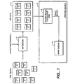
A process flow for printing a sheet onto an out
media is shown in FIG. 1. A plurality of pages of content 2
are arranged to form a sheet 4 by executing an imposition
process 3. The imposition process receives as inputs the
individual page files, which may be in the form of
Postscript® files, printers marks or other objects to be
marked on the page, and layout information 5. Layout
information 5 describes the layout of the sheet including
the location of each object on the sheet. The output of the
imposition process is a PDL file that describes the entire
sheet 4. The PDL file describing the sheet is transferred
to a printing device 6 for printing.
-
Printing devices that produce output in response to
PDL input are widely used. In order to produce a finished
sheet, the printing device interprets the data contained in
the PDL file, renders objects within the data into bitmaps,
and after all objects for the sheet are rendered, prints the
sheet. More specifically, printing device 6 includes a
raster image processor (RIP) 8. RIP 8 renders objects
within the PDL file into bitmaps which are transferred to a
print engine (not shown) for printing onto the output media.
Summary
-
In general, in one aspect, the invention provides a
method for imposing and rendering image data. The method
formatting the image data for a surface of a media sheet in
an output device space and including receiving one or more
page description files defining one or more objects to be
located on the surface of the media sheet, receiving a job
ticket defining a layout of the objects on the surface in a
sheet-defined space. Prior to ripping, the layout of the
objects is transformed into output device space including
rotation or translation of the objects. The objects are
ripped creating raster data that is oriented in output
device space. The raster data is butted in blocks without
shifting the raster data.
-
Aspects of the invention include numerous features.
The method can include printing the raster data on the
surface of the media sheet. An ordered list of objects can
be constructed for the surface from the position of each
page in output device space and the objects can be ripped in
order in accordance with the ordered list. The step of
blitting includes compositing objects into a sheet frame
buffer. The objects can be ripped in parallel.
-
The job ticket definition includes a translation
matrix for each object where the translation matrix
describes a location of the object on the surface in sheet-space
after translation or rotation of the object to
facilitate post printing operations. The translation matrix
may include transformations from bottling and shingling
operations. The method includes adjusting rip parameters
for the surface in accordance with the output device and
ripping the objects using the adjusted rip parameters. The
page description files are PDF files. The method includes
translating all page description files received into PDF
files prior to ripping. The method can be performed in a
printing device where the printing device is selected from
the group of an imagesetter, a digital press, a printing
press and a plate setter.
-
The step of ripping includes rendering each object
creating raster data oriented in output device space.
The step of butting includes compositing objects into a
sheet frame buffer. The step of blitting includes
compositing the objects into bands for storage in a band
buffer. The step of transforming the layout includes
transforming the layout to support bottling or shingling
operations.
-
In another aspect, the invention provides a method
for bottling image data and includes receiving one or more
page description language files defining one or more objects
to be displayed on the surface of the media sheet, bottling
the objects including defining a rotational or translational
transformation of the objects, ripping the objects to
produce raster data that is bottled and blitting the raster
data.
-
In another aspect, the invention provides a method
for shingling image data and includes receiving one or more
page description language files defining one or more objects
to be displayed on the surface of the media sheet, shingling
the objects including defining a rotational or translational
transformation of the objects, ripping the objects to
produce raster data that is shingled and butting the raster
data.
-
In another aspect the invention provides a printing
device configured to receive a plurality of page description
language descriptions of pages to be printed on a sheet and
includes an assembler connected to receive a job ticket
including layout and page identifier information for one or
more objects to be printed on a sheet and operating to
transform the objects from a sheet-defined space to a
printer device space. The printing device includes
plurality of render engines each operating on objects to
produce raster data associated with portions of the sheet
and blitter engine operable to blit the raster data in
blocks without shifting the raster data.
-
Among the advantages of the invention are one or
more of the following. Pages of a sheet may be ripped in
parallel. Bottling and output media orientation issues can
be resolved prior to rendering to facilitate efficient post
RIP blitting operations.
-
Other features and advantages of the invention will
become apparent from the following description and from the
claims.
Brief Description of the Drawings
-
- FIG. 1 is a process flow of a prior art printing
process
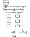
- FIG. 2 is a block diagram of a printer according to
the invention.
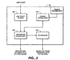
- FIG. 3 is a block diagram of an assembler according
to the invention.
- FIG. 4 is a flow chart for a rendering and marking
process for a raster output device including bottling and
orientation prior to the RIP process according to the
invention.
-
Detailed Description
-
The present invention may be embodied in any output
device that receives page description data and produces from
the data visual output, for example on a piece of paper. An
output device may include a prepress routine for
implementing layout functions, one or more raster image
processors for producing pixelmaps (or bitmaps depending on
the depth of the resultant data) from received data and one
or more engines for producing images on varied output media.
The invention has particular applicability to printing
presses, imagesetters, plate setters, digital presses and
the like and will be described in terms of an embodiment in
such a device, which will be referred to simply as an
imagesetter.
-
Referring to FIG. 2, an imagesetter 16 receives
input data files, from a computer 12, for example, and turns
the input data files into marks on a piece of paper by
sending signals to a print engine 34. The imagesetter 16 is
configured to receive page description language input data
files and layout information from one or more users and
process it as will be described later. One suitable page
description language is the Portable Document Format (PDF)
available from Adobe Systems Incorporated of San Jose,
California. Another suitable page description language is
the PostScript® language available from Adobe Systems
Incorporated of San Jose, California. The PostScript
language is described in Adobe Systems Incorporated, Adobe
PostScript® Language Reference Manual, Addison-Wesley (2d
ed., ©1990). Another suitable page description language is
the PCL language available from Hewlett-Packard Company of
Palo Alto, California. Another page description language is
CT and LW by Scitex America, Inc., of Bedford Massachusetts.
A page description language file sent to an imagesetter
specifies objects to be displayed and related information.
A PostScript object can, for example, include a pixelmap
defining a pattern of pixels to be displayed, or it can
reference an outline curve defining in mathematical terms a
shape to be marked. The object can also include other
rasterizing information such as font and size.
-
Imagesetter 16 includes an interface 24, file
storage 25, a digital data processor, random access memory
28, and one or more print engines 34. It also includes
read-only memory, I/O interfaces, and data transfer paths
and busses, none of which are shown, for storing and
transferring data in support of the functions described
below.
-
Interface 24 regulates the flow of information
between imagesetter 16 and computer 12 according to a
standard communication protocol. Alternatively, interface
24 can support a file transfer protocol for sharing files
between computers in networks on a intranet or internet.
Interface 24 can include a buffer for buffering data
received from computer 12 in the event imagesetter 16 is not
ready to process or otherwise unable to manipulate the
received data. The butter can be part of file storage 25.
-
File storage 25 is a mass storage device such as
hard disk or disk array for storing files received from
computer 12. Each file includes one or more objects
associated with a given sheet to be outputted by the
imagesetter. Imagesetter 16 can store all the files
associated with a particular sheet in file storage 25 prior
to rendering data objects associated with a given file.
Alternatively, imagesetter 16 can begin render operations
prior to the receipt of all page description files based on
the availability of a job ticket and the receipt of the page
description file page(s) associated with the first object(s)
to be rendered in printing the sheet. The rendering process
is described in greater detail below.
-
The processor can be a general or special purpose
microprocessor operating under control of computer program
instructions executed from a memory. In the implementation
illustrated in FIG. 2, the processor includes a number of
special purpose sub-processors including an assembler 40,
one or more raster image processors (RIPS) 42 and blitter
engines 44. Each sub-processor can be a separate circuit
able to operate substantially in parallel with the other
sub-processors. Some or all of the sub-processors can be
implemented as computer program processes (software)
tangibly stored in a memory to perform their respective
functions. These can share an instruction processor, such
as a general purpose integrated circuit microprocessor, or
each sub-processor can have its own microprocessor for
executing instructions. Alternatively, some or all of the
sub-processors can be implemented in an ASIC (application
specific integrated circuit). In addition, the sub-processors
can be distributed or form a part of computer 12.
-
Assembler 40 provides front end services for
scheduling and initiating the parallel ripping of pages that
are to be printed in a sheet. Referring now to Fig. 3,
assembler 40 includes a scheduler 100, imposition consultant
102, engine consultant 104 and job ticket player 106.
-
Engine consultant 104 generates print engine
specific data related to the particular print engine 34 that
is to be used in printing a particular sheet. Imagesetter
16 can include a plurality of print engines 34 for printing
onto a plurality of output media. Engine consultant 104
maintains print engine specific data for each print engine
34 supported by imagesetter 16. The print engine specific
data includes raster width and height, resolution, margins,
scan direction and feed direction.
-
Job ticket player 106 receives as an input a job
ticket that describes the layout of the various pages on the
sheet. Job tickets are described in greater detail in
commonly owned and co-pending application entitled "In-RIP
Sorting of Objects in the Slow Scan Direction", to Craig
Benson et. al., filed October 16, 1998 and assigned serial
number 09/173,851, the contents of which is expressly
incorporated herein by reference.
-
The job ticket includes layout information including
a list of sheets (surfaces) to be printed and a print engine
identifier for each sheet. The job ticket includes, for
each sheet, an list of objects to be printed on the sheet
and position orientation information for each object. Each
object includes object type, size and placement information.
Object types can be selected from a PostScript or PDF file,
a printers mark, or other proprietary or non-proprietary
type of input.
-
The placement information locates the object on the
sheet and can be in the form of a transformation matrix
which describes the placement of the object on the page
relative to a page origin. The placement information can
include bottling, shingling or other transformations of the
object required to support post-printing processes. In one
implementation, a transformation matrix and a clip path are
used to locate each object on the sheet. The transformation
matrix defines where on the sheet surface a particular
object is to be placed and includes any translation and/or
rotation to be applied to the object. The clip path
indicates any clipping to be done to the particular object
prior to placement at the location indicated by the
transformation matrix. For each sheet, job ticket player
106 provides an object list and associated object
information to the imposition consultant 102.
-
Imposition consultant 102 receives as input an
object list for a sheet and engine parameters associated
with the particular print engine that is to print the sheet.
The engine parameters are retrieved from engine consultant
106 based on the print engine identifier for the given
sheet. The engine parameters include the scan direction and
feed direction associated with the particular print engine
34. In addition, imposition consultant 102 passes sheet
size and resolution information to engine consultant 104
which in turn returns raster height, width, margin and other
print engine specific information describing the output
device space. Imposition consultant 102 includes a sorting
engine 108 for sorting the object list based on the engine
parameters. In one implementation, all the objects are
sorted in the slow scan direction of the printing engine
while maintaining the relative order found in the object
list when considering overlapping objects. The sorted list
is provided to scheduler 100.
-
For each object to be placed on a sheet, imposition
consultant 102 determines the orientation of the object to
the media and the media scan direction and adjusts the
transformation matrix for each object based on the media
scan direction and orientation. The adjustment of the
transformation matrix is described in greater detail below.
-
Imposition consultant 102 generates a description of
the surface to be printed and sends it to a blitter engine
44. Blitter engine 44 constructs the sheet assembling the
individual ripped objects (bitmaps for objects) as they are
produced by the various RIPs 42. The description provided
by the imposition consultant 102 includes placement and
paint order information for each object to be painted on the
sheet.
-
In addition, imposition consultant 102 calculates
RIP parameters (engine margins, raster width, height,
orientation (portrait or landscape)) for each object based
on the engine parameters and object information provided
from job ticket player 106.
-
Scheduler 100 processes the ordered lists. For each
list, scheduler extracts objects in order and passes the
objects along with RIP parameters generated by the
imposition consultant 102 to RIPs 42 for processing.
-
Imagesetter 16 can include a plurality of RIPs 42.
Each RIP receives as an input an object to be ripped and RIP
parameters for controlling the render process. A RIP
converts the high level object description into a bitmap for
storage in a raster buffer. The output of a RIP is a bitmap
describing the object which in turn is provided as an input
to a blitter engine 44. For example, where the object
processed is a page to be printed on the output media, a RIP
42 produces raster data which is a superset of the original
page such that the rotated and offset page fits within the
non-rotated sheet frame buffer.
-
In one implementation, each RIP is identical, and
can be used to process any object to be painted on the
sheet. Plural RIPs allows for the simultaneous processing
of objects and speeds the assembly process. Alternatively,
RIPs 42 can be of different types allowing for customized
processing of objects of differing types. For example,
imagesetter 16 can include separate RIPs for processing
graphics and text type objects. RIPs can be customized to
speed the raster generation process.
-
Scheduler 100 oversees the delivery of objects to
the individual RIPs 42. In one implementation, objects are
screened based on object type and provided to the
appropriate RIPs as the RIPs become available. To avoid a
bottleneck condition at a single RIP, multiple RIPs of the
same type can be included. Alternatively, general purpose
RIPs can be included for processing all types of objects.
After the successful rendering of an object (or portion of
an object attributable to a band being rendered) and
subsequent transfer of a bitmap to a blitter engine, a RIP
42 can request another object for processing. Scheduler 100
services the requests from the plurality of RIPs and passes
objects and RIP parameter information to each RIP in
accordance with the ordered list.
-
A blitter engine 44 assembles a sheet based on the
description provided by the imposition consultant 102 by
compositing each object into a sheet raster buffer (frame
buffer). The description includes placement and paint order
information for each object to be painted on the sheet. The
butter engine retrieves pixelmaps from a RIP based on the
paint order and draws the pixelmap into the frame buffer.
Objects are extracted from the various RIPs in order to
support the assembly of the sheet in accordance with the
scan direction and feed direction of the print engine. The
frame buffer is oriented in output device space. Objects
are painted into the frame buffer based on the location
information provided from the imposition consultant. The
pixelmaps retrieved from the RIPs are properly oriented in
device space and are not required to be further manipulated
or transformed by the blitter engine 44. The output of each
RIP is a band of transformed (oriented) data that is painted
into the sheet frame buffer by the blitter. Accordingly,
block blitting of the data received from the RIPs into the
sheet frame buffer can be realized.
-
After all of the objects associated with a given
sheet (surface) have been rendered by a RIP 42 and assembled
by a blitter engine into a sheet in the frame buffer, the
pixelmap data stored in the frame buffer can be applied to
the media by the designated print engine 34. Alternatively,
the frame buffer can be sized to store only a portion of the
sheet. The print engine can be activated prior to ripping
all of the objects for a sheet after an initial portion of
data (a band) is processed by blitter engine 44 as will be
described in greater detail below.
-
Imagesetter 16 can include a plurality of blitter
engines for constructing a plurality of sheets (surfaces).
Separate blitter engines can be used for each color plane in
a color printing application. Alternatively, a sheet can be
divided into sub-portions and a blitter engine can be
assigned to assemble the particular sub-portion.
-
RAM 28 is a random access memory used by the
processor (sub-processors 40-44). RAM 28 can be embodied in
one or more memory chips. The memory can be partitioned or
otherwise mapped to reflect the boundaries of the various
memory sub-components. RAM 28 can include a frame buffer
for storing a sheet, or portion thereof, prior to printing
by a print engine.
-
Data flow, rather than physical interconnection, is
illustrated between elements of imagesetter 16. Processor
and memory components are physically interconnected using a
conventional bus architecture.
-
The imagesetter components that have been described
can be packaged in a single product; alternatively, some can
be included in computer 12 or otherwise housed separately.
-
Referring now to FIGS. 3 and 4, a conventional
rendering and marking process for a raster output device is
enhanced by the addition of a method 400 of pre-rip bottling
and orientation. Imagesetter 16 receives one or more PDL
files representative of pages or sub-pages to be displayed
on a given sheet from computer 12 (402). The files are
transferred to file storage 25 for storage until a RIP
process is invoked (404).
-
Assembler 40 receives a job ticket associated with
one or more sheets to be processed (406). The job ticket
defines both media requirements, document location and
layout for each content element to be placed in a final
sheet. In one embodiment, assembler 40 waits until all of
the files associated with a given sheet have been received
and stored in file storage 25 before beginning the assembly
process. Alternatively, assembler 40 can begin the assembly
process after the job ticket and a first file is received.
-
Imposition consultant 102 in assembler 40 processes
each job ticket and creates for each surface (where a sheet
may have more than one surface, e.g., top surface and bottom
surface of a single sheet) a list of objects to be printed
on a given surface (408). Each entry includes an object
identifier (number), transformation matrix information and
clipping information associated with the object which is
derived from the job ticket. As described above, the
transformation matrix indicates sheet placement for a given
object.
-
Engine parameters associated with the particular
print engine that is to print the sheet are retrieved (410).
More specifically, imposition consultant 102 queries engine
consultant 104 for the particular engine parameters
associated with the print engine as designated by the print
engine identifier for the sheet. Engine consultant 104
returns engine specific information including raster edge
width and height, long edge, short edge, scan direction, and
feed direction. Imposition consultant 102 adjusts the
placement of each object based on the specific print engine
parameters (412). More specifically, imposition consultant
102 rotates and transforms the transformation matrix and, as
appropriate, the clip path, to locate the object in device
space.
-
A bounding box associated with the rotated and
translated clip path as defined by the adjusted
transformation matrix is produced (414). The bounding box
defines a region in output device space that is to contain
the raster data associated with the object. The actually
area for the raster data is determined by the RIP and may or
may not exactly conform to the calculated bounding
information developed by the imposition consultant depending
on the RIP performance or other limitations. The scan unit
boundaries for the clip path are determined (416). The
objects in the list are then sorted based on the slow scan
and feed direction (418).
-
A description of the sheet is provided to a blitter
engine 44 (422). The description includes placement and
paint order information for each object to be placed on the
sheet and can include the bounding box information. The
placement information is in the form of a destination
address in output device space at which the blitter engine
is to start to paint the raster data associated with the
given object.
-
Finally, the imposition consultant calculates RIP
parameters for each object (424) and passes the sorted
object list and RIP parameters to a scheduler for processing
(426). The RIP parameters include object size, raster
buffer size to be marked (in device pixels) and the margins
(in device pixels). The object size defines the physical
dimensions of the object in the output media. The margins
reflect the offset from the page origin location, e.g.,
PostScript (0,0), to the nearest corner in the raster
buffer.
-
As RIPs become available, the scheduler 100 in
assembler 40 sends the individual objects to a RIP for
rendering in accordance with the specified RIP parameters
(428). When all of the objects associated with a first band
to be painted on the sheet have been rendered by a RIP,
blitter engine 44 retrieves the bitmap(s) and paints the
bitmap(s) into a frame buffer (430). The blitter engine
retrieves objects in order from the RIPs based on the
ordering received as part of the description from the
imposition consultant. The painting of the bitmaps into the
frame buffer is performed in accordance with the placement
information received as part of the description. More
specifically, the placement information includes a starting
address in output device space for painting the given
object. The RIP provides the raster data to the butter
engine upon request as well as a definition of the raster
height and width that is to be painted. The blitter engine
starts the paint at the designated starting address and
advances to new scanlines depending on the height and width
information.
-
In one implementation, scheduler 100 divides and
sorts each object (based on its respective location in the
final sheet as defined by the transformation matrix data
derived in step 412) into one or more bands associated with
the output media. Each band can contain one or more objects
(display data) or portions of objects. When all of the
objects for a given band in a surface to be printed have
been received, then the scheduler can send the objects to a
RIP to produce pixelmaps. The resultant pixel data can be
painted into one or more band buffers of varied size
(typically 256, 512 or 1024 scan tines in size) rather than
a frame buffer.
-
After all of the display data is assembled by
blitter engine 44, the resultant pixelmap data can be sent
to print engine 34 for printing the particular surface
(432). The pixelmap data can be sent to the print engine a
band at a time as soon as the bands are rendered.
Alternatively, the pixelmaps can be stored in a data storage
mechanism (such as file storage 25) for printing at a later
time.
-
The present invention has been described in terms of
specific embodiments, which are illustrative of the
invention and not to be construed as limiting. The
invention can be implemented in hardware, firmware or
software, or in a combination of them. Other embodiments
are within the scope of the following claims.