EP1016374A1 - Arthroscopic measuring device - Google Patents
Arthroscopic measuring device Download PDFInfo
- Publication number
- EP1016374A1 EP1016374A1 EP99310548A EP99310548A EP1016374A1 EP 1016374 A1 EP1016374 A1 EP 1016374A1 EP 99310548 A EP99310548 A EP 99310548A EP 99310548 A EP99310548 A EP 99310548A EP 1016374 A1 EP1016374 A1 EP 1016374A1
- Authority
- EP
- European Patent Office
- Prior art keywords
- measuring
- handle
- tip
- actuator
- distance
- Prior art date
- Legal status (The legal status is an assumption and is not a legal conclusion. Google has not performed a legal analysis and makes no representation as to the accuracy of the status listed.)
- Granted
Links
Images


Classifications
-
- A—HUMAN NECESSITIES
- A61—MEDICAL OR VETERINARY SCIENCE; HYGIENE
- A61B—DIAGNOSIS; SURGERY; IDENTIFICATION
- A61B5/00—Measuring for diagnostic purposes; Identification of persons
- A61B5/103—Detecting, measuring or recording devices for testing the shape, pattern, colour, size or movement of the body or parts thereof, for diagnostic purposes
- A61B5/107—Measuring physical dimensions, e.g. size of the entire body or parts thereof
- A61B5/1076—Measuring physical dimensions, e.g. size of the entire body or parts thereof for measuring dimensions inside body cavities, e.g. using catheters
Definitions
- the present invention relates to a device for measuring distances, lengths, and widths, and more particularly to a device for measuring distances between two points in a surgical setting.
- the present invention comprises a device designed to make measurements between two points within confined spaces, such as within an arthroscopic surgical site.
- the device may be used to make measurements which are not only larger than the incision but also transverse to the direction of extension of arthroscopic instruments.
- the device of the present invention is an instrument comprising an extension for extending into an incision, with a tip for insertion into the incision and a handle for remaining outside the body.
- the tip comprises a pair of measuring ends, the measuring ends at a predetermined angle from each other, and at least one of the measuring ends being movable relative to the tip.
- An actuator at the handle moves at least one of the measuring ends relative to the tip.
- a pair of elongated tubes are provided to house a pair of wires.
- the tubes extend from a handle to a measuring tip.
- An actuator comprising a button positioned in the handle, is connected to the wires.
- the wires extend out of the tip at a predefined angle.
- Calibrations are provided on the handle to correspond to the distance between the tips of the wires.
- the extension and retraction of the measuring wires is controlled by a button located on the handle of the device. Ridges on the button allow the user to operate the device while gripping the device in a comfortable manner.
- the wires are controlled by an actuator comprising plunger mechanism, in which the user pushes the plunger into the handle, which in turn controls extension and retraction of the wires.
- an actuator comprising plunger mechanism, in which the user pushes the plunger into the handle, which in turn controls extension and retraction of the wires.
- buttons 30 distally or pull button 30 proximally.
- wires 40, 42 are also pushed distally and extend through apertures 26, 28 at tip 16.
- a set of calibrations 72 adjacent to button 30 on a top face 39 of button 30 corresponds to distance 48 between measuring ends 44 and 46. Thus, distances may be measured with measuring ends 44 and 46, and such distances may be read proximally on calibrations 72 of handle 36.
- wires 40 and 42 emerge from apertures 26, 28 at a predetermined angle 50, for example 20°.
- angle 50 remains the same, but transverse distance 48 between ends 44 and 46 increases.
- calibrations 72 may be provided for any given angle 50.
- Instruments with various angles 50 may be provided for use in a variety of applications, even up to 180° for measurements which are truly transverse to the incision.
- the length of tubes 20, 22 may vary depending on the application.
- measuring ends 44 and 46 are shown only slightly extended through apertures 26, 28. In this position, measuring ends 44 and 46 are already spaced apart by somewhat more than the width of tip 16, as indicated by distance 49. Because wires 40, 42 emerge from apertures 26, 28 in a spaced-apart arrangement, calibrations 72 (shown in Fig. 1) on handle 36 start at a measurement which is larger than zero. A set of gradations 52 on a front surface 21 of tip 16 provides for measurements which are smaller than the smallest of calibrations 72. In arthroscopic applications, such gradations 52 may be visualized through use of an arthroscopic camera. Thus, the device 10 of the present invention may provide for continuous measurement from zero to the largest of calibrated measurements 72. As illustrated in Fig.
- front surface 21 is provided with, for example, four gradations 52, which could correspond to measurements of 1 to 4 mm and calibrations 72 start at 5 mm, which would correspond to the distance between measuring ends 44 and 46 as they begin to emerge from tip 16, as shown by distance 49 in Fig. 3.
- gradations 52 which could correspond to measurements of 1 to 4 mm and calibrations 72 start at 5 mm, which would correspond to the distance between measuring ends 44 and 46 as they begin to emerge from tip 16, as shown by distance 49 in Fig. 3.
- the measurements described above are exemplary only.
- the number and size of gradations 52 may vary with the application.
- Figs. 4 to 6 illustrate alternative embodiments for tip 16.
- front surface 21 is rounded, to provide for easier insertion into an operative site. Because front surface 21 is rounded, it may be more difficult to provide gradations on front surface 21. Instead, it may be preferred to provide the gradations on a more linear surface, such as side surface 15 (gradations not shown).
- Fig. 5 The embodiment of Fig. 5 is quite similar to the embodiment shown in Figs. 3 and 4. However, unlike the embodiment shown in Figs. 3 and 4, there is no front surface bridging tubes 20, 22. Instead, in this embodiment, tubes 22, 22 provide a valley 47. As illustrated, three gradations 52, corresponding to measurements of 1 to 3 mm, provide for small measurements. A width 14 of an absolute distal terminus 12 corresponds to a measurement of 4 mm, and calibrations can start at 5 mm, thus providing for continuous measurements. However, as with the embodiment illustrated in Fig. 3, the number and size of gradations 52 may vary with the application.
- An alternative embodiment is for a tip 16' to terminate at a single fixed point 46', as shown in Fig. 6.
- a measuring device of this embodiment would be provided with only one tube 20' and only a single wire 40' for extending from and retracting into a tube 54' at orifice 28'.
- Single wire 40' would be offset from the point by a predetermined angle 50'. Measurements would be taken as a distance 48' from fixed point 46' to measuring end 44' of wire 40'.
- angle 50' may vary with application, and may include angles as small as 0° and as large as 180°. As with the illustrative embodiment, one skilled in the art could easily determine the proper calibrations.
- Fig. 7 is a perspective view of button 30 as it appears separately from handle 36.
- Button 30 is provided with slide 64, rod 66, and block 60.
- Rod 66 is positioned and sized to slide in a proximo-distal direction within axial cavity 35 of handle 30.
- Slide 64 is designed to lay mostly or completely exterior to top face 39 of handle 30.
- Block 60 connects rod 66 to slide 64, and block 60 is designed to slide within slot 34.
- Wires 40, 42 extend distally from a distal face 62 of rod 66. As shown, wires 40, 42 are embedded in distal face 62 of block 66 by means of a pair of orifices 56, 57.
- other attachment configurations are possible and should be considered within the scope of this invention.
- slide 64 of button 30 has a proximal end 31, a distal end 33, and a plurality of ridges 68, 69, 70, 71 between proximal end 31 and distal end 33.
- Button 30 is shown in a proximal position, in which proximal end 31 of slide 64 is adjacent proximal end 37 of handle 36.
- wires 40, 42 are preferably completely retracted within tubes 20, 22 and do not extend beyond orifices 26, 28 at tip 16 (not shown).
- the user may use any one or more of ridges 68, 69, 70, 71 to slide button 30 distally. As button 30 is moved distally, distal end 33 of slide 64 will move along calibrations 72.
- a corresponding calibration marking 80 indicates distance 48 between measuring ends 44 and 46 (shown in Fig. 2).
- distance 48 between measuring ends 44 and 46 would be the distance indicated by first calibration marking 82. In the illustrative example, this would be 5 mm, and the position of wires 40, 42 at tip 16 may appear as shown in Fig. 3.
- the position shown in Fig. 1 illustrates button 30 in a more intermediate position.
- measuring device 10 is provided with slot 34 in handle 36 which, as illustrated, can be seen adjacent to proximal edge 31 and adjacent to distal edge 33 of button 30.
- handle 36 is provided with axial cavity 35. As shown, axial cavity 35 extends through most of handle 36.
- Figs. 9 and 10 illustrate device 10 configured such that axial cavity 35 and slot 34 prevents excessive proximo-distal movement of button 30, restricting button 30 and wires 40, 42 to a preset length of travel.
- Fig. 9 illustrates handle 36 with button 30 in the proximal-most position. In this position, a proximal end 58 of block 60 is in contact with a proximal end 86 of slot 34.
- a proximal face 63 of rod 66 is in contact with proximal end 84 of axial cavity 35.
- Fig. 10 illustrates button 30 in the distal-most position.
- a distal end 59 of block 60 is in contact with a distal end 87 of slot 34.
- axial cavity 35 extends all the way to distal end 38 of handle 36, in order to provide passage for wires 40, 42 to extend to tubes 20, 22.
- distal face 62 of rod 66 does not contact the absolute distal end 85 of axial cavity 35.
- axial cavity 35 narrows at a transition 88, which provides additional restraint.
- proximal end 86 and distal end 87 of slot 34 provide stops for button 30, axial cavity 35 may maintain the same diameter throughout the length of handle 36. Additional stability is provided by block 60 and slot 34, which prevent button 30 from twisting relative to handle 36 and prevents wires 40, 42 from twisting within handle 36.
- constraint against excessive proximo-distal and twisting motion is a preferred embodiment. Other configurations are possible within the scope of the present invention.
- button 30 directly connected to wires 40, 42 inside handle 36.
- button 30 may be connected to wires 40, 42 by a series of gears or pulleys, or by various other mechanisms.
- the illustrative embodiments comprise mechanical calibrations and indicators. Various other mechanisms for indicating the measurements are within the scope of this invention. For instance, an electronic display indicator with digital calibrations may be used. These and other alternative embodiments are within the scope and spirit of this invention.
- rod 66 and axial cavity 35 may be in sufficient frictional contact that button 30 will remain fixed in position relative to handle 36 until the user pushes or pulls button 30. The button 30 will then remain fixed in its new position until the user once again changes the position.
- a spring 90 may be provided within handle 36. As shown in Fig. 11, spring 90 is located within axial cavity 35 between rod 66 and transition 88 of axial cavity 35. Spring 90 bears on transition 88 and distal face 62 of rod 66, and spring 90 biases rod 66 against proximal end 84 of axial cavity 35. In this position, wires 40, 42 would be, preferably, fully retracted within tubes 20, 22. Distal pressure on button 30 would push button 30 distally, which would push wires 40, 42 out from apertures 26, 28. However, once the pressure is released, spring 90 would cause wires 40, 42 to retract automatically to the starting position, as shown in Fig. 11.
- the measuring device of Fig. 1 may be used by inserting tip 16 and a portion of extension 23 into a small incision of a patient. Button 30 is then used to push wires 40, 42 through apertures 26, 28 until measuring ends 44, 46 span the distance to be measured. Handle 36 remains outside of the patient's body, and the distance between measuring ends 44, 46 may be read on handle 36 as the calibration 72 then indicated.
- Figs. 12 and 13 illustrate an alternative embodiment 110 of the present invention.
- Fig. 12 shows generally measuring device 110.
- Device 110 is provided with a sleeve 120 and a plunger 130.
- sleeve 120 is elongated.
- Sleeve 120 is provided with a tip 122 at a distal end 118 and a head 124 at a proximal end 119.
- Plunger 130 telescopes within sleeve 120 at head 124.
- a pair of wires 140, 142 are pushed out of a pair of apertures 126, 128 at tip 122.
- the further plunger 130 is pushed within sleeve 120, the more of wires 140, 142 extend from tip 122, and the greater a distance 148 between a pair of measuring ends 144 and 146.
- a set of calibrations 132 on plunger 130 corresponds to distance 148 between measuring ends 144 and 146.
- wires 140, 142 are separated by a predetermined angle 150, for instance 20°.
- angle 150 As the distance from a front surface 121 to the measuring ends 144, 146 increases, angle 150 remains the same, but the distance 148 (shown Fig. 12) between measuring ends 144, 146 increases.
- one skilled in the art could easily calculate the appropriate calibrations 132 for a given angle of 150. Instruments with various angles 150 could be provided for use in a variety of applications.
- wires 140, 142 emerge through apertures 126, 128.
- apertures 126, 128 are located in side surfaces 127, 129 adjacent to the front surface 121 of tip 122.
- a set of gradations 152 at front surface 121 provide for measurements which are smaller than the first of calibrations 132.
- front surface 121 is provided with four gradations 152, which could correspond to measurements of 0 to 4 mm, the width of tip 122 may correspond to 5 mm, and calibrations 132 may start at 6 mm.
- angle 150 the number and size of gradations may vary with the application.
- distance 148 between measuring ends 144, 146 may be read as the specific calibration marking 132 which is adjacent to an opening 134 in a sleeve head 124.
- a window may be provided within sleeve 120, in which the calibration would appear which corresponds to distance 148.
- measuring device 110 is provided with a pair of finger rings 138, 139 on sleeve 120 and a thumb ring 136 on plunger 130. This configuration allows the user both to push and pull the plunger 130 with relative ease. However, numerous other gripping configurations are possible.
- the illustrative embodiment is provided with a slot 162 in sleeve 120.
- a pin 160 affixed to a portion of plunger 130 inside of sleeve 120, engages slot 162.
- Proximal end 164 and distal end 166 of slot 162 restrain pin 160 and prevent excessive movement of pushing or pulling on plunger 130.
- pin 160 and slot 162 prevent plunger 130 and wires 140, 142 from twisting within sleeve 120.
- Other configurations are possible within the scope of the present invention.
- the arthroscopic measuring device of this invention may be substantially straight and rigid, for measuring distances which are transverse to the straight longitudinal axis of the device. It will also be understood that the tubes and wires may be curved, for arthroscopic applications where a straight instrument would not be useful. Finally, the tubes and wires may be made of somewhat flexible materials, which may bend as needed in arthroscopic surgery.
Abstract
Description
- The present invention relates to a device for measuring distances, lengths, and widths, and more particularly to a device for measuring distances between two points in a surgical setting.
- In many surgical settings, it is often necessary for the surgeon to make measurements. Due to the confined spaces of arthroscopic surgery, measuring distances is often quite difficult, particularly when the measurement needed is larger than the size of the incision or transverse to the direction of extension of the arthroscopic instruments. Arthroscopic knee surgery provides many such situations. For example, it may be helpful if a surgeon could measure the size of a defect in the condyle of a knee, to aid in choosing the appropriate method to repair the defect.
- The present invention comprises a device designed to make measurements between two points within confined spaces, such as within an arthroscopic surgical site. Preferably, the device may be used to make measurements which are not only larger than the incision but also transverse to the direction of extension of arthroscopic instruments.
- The device of the present invention is an instrument comprising an extension for extending into an incision, with a tip for insertion into the incision and a handle for remaining outside the body. The tip comprises a pair of measuring ends, the measuring ends at a predetermined angle from each other, and at least one of the measuring ends being movable relative to the tip. An actuator at the handle moves at least one of the measuring ends relative to the tip.
- In a preferred embodiment, a pair of elongated tubes are provided to house a pair of wires. The tubes extend from a handle to a measuring tip. An actuator, comprising a button positioned in the handle, is connected to the wires. As the device is operated, the wires extend out of the tip at a predefined angle. Calibrations are provided on the handle to correspond to the distance between the tips of the wires. Thus, when the tip is inserted into an incision, distances transverse to the direction of the shaft can be measured quickly and easily.
- Preferably the extension and retraction of the measuring wires is controlled by a button located on the handle of the device. Ridges on the button allow the user to operate the device while gripping the device in a comfortable manner. In an alternative embodiment, the wires are controlled by an actuator comprising plunger mechanism, in which the user pushes the plunger into the handle, which in turn controls extension and retraction of the wires. Other arrangements are possible within the scope of this invention.
- Additional features of the present invention will become apparent to those skilled in the art upon consideration of the following detailed description of preferred embodiments exemplifying the best mode of carrying out the invention as presently perceived.
- The invention will now be described by way of example with reference to the accompanying drawings, in which:
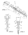
- Fig. 1 is a perspective view of a measuring device of this invention, including a handle, a pair of tubes extending distally from the handle and terminating in a tip, a button seated in the handle, and a pair of wires protruding from the tip;
- Fig. 2 is a top view of the tip of the measuring device of Fig. 1;
- Fig. 3 is similar to Fig. 2, except showing gradations for small measurements;
- Fig. 4 is similar to Fig. 2, except showing an alternative embodiment including a rounded front surface;
- Fig 5 is similar to Fig. 2, except showing an alternative embodiment having a gap between the wires at the tip;
- Fig. 6 is similar to Fig. 2, except showing an alternative embodiment including one wire;
- Fig. 7 is a perspective view of the button of Fig. 1, showing wires extending distally therefrom;
- Fig. 8 is a top elevational view of the handle of Fig. 1, showing the button and calibrations;
- Fig. 9 is a side cross-sectional view of the handle of Fig. 1, showing the button in a proximal location;
- Fig. 10 is similar to Fig. 9, except showing the button in a distal location;
- Fig. 11 is similar to Fig. 9, except further comprising a spring to bias the button to the proximal position;
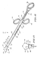
- Fig. 12 is a perspective view of an alternative embodiment of a measuring device of this invention; and
- Fig. 13 is a top view of the tip of the measuring device of Fig. 12. Referring to the drawings, Fig. 1 shows generally a
-
- In operation, the user may push
button 30 distally or pullbutton 30 proximally. Asbutton 30 is pushed distally withinhandle 36, in the direction indicated by the arrow shown in Fig. 1,wires apertures tip 16. Themore button 30 is pushed distally, thefarther wires tip 16, and the greater a distance 48 (shown in Fig. 2) between a pair ofmeasuring ends calibrations 72 adjacent tobutton 30 on atop face 39 ofbutton 30 corresponds todistance 48 between measuringends ends calibrations 72 ofhandle 36. - As illustrated in Fig. 2,
wires apertures predetermined angle 50, for example 20°. As the distance fromtip 16 to measuringends angle 50 remains the same, buttransverse distance 48 betweenends calibrations 72 may be provided for any givenangle 50. Instruments withvarious angles 50 may be provided for use in a variety of applications, even up to 180° for measurements which are truly transverse to the incision. Similarly, the length oftubes - Referring now to Fig. 3,
measuring ends apertures ends tip 16, as indicated by distance 49. Becausewires apertures handle 36 start at a measurement which is larger than zero. A set ofgradations 52 on afront surface 21 oftip 16 provides for measurements which are smaller than the smallest ofcalibrations 72. In arthroscopic applications,such gradations 52 may be visualized through use of an arthroscopic camera. Thus, thedevice 10 of the present invention may provide for continuous measurement from zero to the largest ofcalibrated measurements 72. As illustrated in Fig. 3,front surface 21 is provided with, for example, fourgradations 52, which could correspond to measurements of 1 to 4 mm andcalibrations 72 start at 5 mm, which would correspond to the distance betweenmeasuring ends tip 16, as shown by distance 49 in Fig. 3. However, the measurements described above are exemplary only. The number and size ofgradations 52 may vary with the application. - Figs. 4 to 6 illustrate alternative embodiments for
tip 16. In Fig. 4,front surface 21 is rounded, to provide for easier insertion into an operative site. Becausefront surface 21 is rounded, it may be more difficult to provide gradations onfront surface 21. Instead, it may be preferred to provide the gradations on a more linear surface, such as side surface 15 (gradations not shown). - The embodiment of Fig. 5 is quite similar to the embodiment shown in Figs. 3 and 4. However, unlike the embodiment shown in Figs. 3 and 4, there is no front
surface bridging tubes tubes valley 47. As illustrated, threegradations 52, corresponding to measurements of 1 to 3 mm, provide for small measurements. A width 14 of an absolutedistal terminus 12 corresponds to a measurement of 4 mm, and calibrations can start at 5 mm, thus providing for continuous measurements. However, as with the embodiment illustrated in Fig. 3, the number and size ofgradations 52 may vary with the application. - An alternative embodiment is for a tip 16' to terminate at a single fixed point 46', as shown in Fig. 6. A measuring device of this embodiment would be provided with only one tube 20' and only a single wire 40' for extending from and retracting into a tube 54' at orifice 28'. Single wire 40' would be offset from the point by a predetermined angle 50'. Measurements would be taken as a distance 48' from fixed point 46' to measuring end 44' of wire 40'. As with other embodiments, angle 50' may vary with application, and may include angles as small as 0° and as large as 180°. As with the illustrative embodiment, one skilled in the art could easily determine the proper calibrations.
- Fig. 7 is a perspective view of
button 30 as it appears separately fromhandle 36.Button 30 is provided withslide 64,rod 66, and block 60.Rod 66 is positioned and sized to slide in a proximo-distal direction withinaxial cavity 35 ofhandle 30.Slide 64 is designed to lay mostly or completely exterior totop face 39 ofhandle 30.Block 60 connectsrod 66 to slide 64, and block 60 is designed to slide withinslot 34.Wires distal face 62 ofrod 66. As shown,wires distal face 62 ofblock 66 by means of a pair oforifices - Referring to Fig. 8, slide 64 of
button 30 has aproximal end 31, adistal end 33, and a plurality ofridges proximal end 31 anddistal end 33.Button 30 is shown in a proximal position, in whichproximal end 31 ofslide 64 is adjacentproximal end 37 ofhandle 36. Whenbutton 30 is in this position,wires tubes orifices ridges button 30 distally. Asbutton 30 is moved distally,distal end 33 ofslide 64 will move alongcalibrations 72. Whendistal end 33 ofslide 64 reaches one of a plurality ofcalibration lines 74, a corresponding calibration marking 80 indicatesdistance 48 between measuring ends 44 and 46 (shown in Fig. 2). For example, whendistal end 33 ofslide 64 contacts afirst calibration line 78,distance 48 between measuring ends 44 and 46 would be the distance indicated by first calibration marking 82. In the illustrative example, this would be 5 mm, and the position ofwires tip 16 may appear as shown in Fig. 3. The position shown in Fig. 1 illustratesbutton 30 in a more intermediate position. - As seen in Fig. 1 the illustrative embodiment of measuring
device 10 is provided withslot 34 inhandle 36 which, as illustrated, can be seen adjacent toproximal edge 31 and adjacent todistal edge 33 ofbutton 30. Also, handle 36 is provided withaxial cavity 35. As shown,axial cavity 35 extends through most ofhandle 36. Figs. 9 and 10 illustratedevice 10 configured such thataxial cavity 35 andslot 34 prevents excessive proximo-distal movement ofbutton 30, restrictingbutton 30 andwires button 30 in the proximal-most position. In this position, aproximal end 58 ofblock 60 is in contact with aproximal end 86 ofslot 34. Also, aproximal face 63 ofrod 66 is in contact withproximal end 84 ofaxial cavity 35. Thus, no further proximal movement ofbutton 30 is possible. Fig. 10 illustratesbutton 30 in the distal-most position. Adistal end 59 ofblock 60 is in contact with adistal end 87 ofslot 34. In the illustrated embodiment,axial cavity 35 extends all the way todistal end 38 ofhandle 36, in order to provide passage forwires tubes distal face 62 ofrod 66 does not contact the absolutedistal end 85 ofaxial cavity 35. However,axial cavity 35 narrows at atransition 88, which provides additional restraint. Alternatively, sinceproximal end 86 anddistal end 87 ofslot 34 provide stops forbutton 30,axial cavity 35 may maintain the same diameter throughout the length ofhandle 36. Additional stability is provided byblock 60 andslot 34, which preventbutton 30 from twisting relative to handle 36 and preventswires handle 36. However, other methods of constraining unwanted motion are within the scope of this invention. It will be understood that constraint against excessive proximo-distal and twisting motion is a preferred embodiment. Other configurations are possible within the scope of the present invention. - The illustrative embodiment has been described with the
button 30 directly connected towires handle 36. However,button 30 may be connected towires - In one embodiment of this invention,
rod 66 andaxial cavity 35 may be in sufficient frictional contact thatbutton 30 will remain fixed in position relative to handle 36 until the user pushes or pullsbutton 30. Thebutton 30 will then remain fixed in its new position until the user once again changes the position. In an alternative embodiment of this invention, as shown in Fig. 11, aspring 90 may be provided withinhandle 36. As shown in Fig. 11,spring 90 is located withinaxial cavity 35 betweenrod 66 andtransition 88 ofaxial cavity 35.Spring 90 bears ontransition 88 anddistal face 62 ofrod 66, andspring 90biases rod 66 againstproximal end 84 ofaxial cavity 35. In this position,wires tubes button 30 would pushbutton 30 distally, which would pushwires apertures spring 90 would causewires - The measuring device of Fig. 1 may be used by inserting
tip 16 and a portion ofextension 23 into a small incision of a patient.Button 30 is then used to pushwires apertures Handle 36 remains outside of the patient's body, and the distance between measuring ends 44, 46 may be read onhandle 36 as thecalibration 72 then indicated. - Figs. 12 and 13 illustrate an alternative embodiment 110 of the present invention. Fig. 12 shows generally measuring device 110. Device 110 is provided with a
sleeve 120 and aplunger 130. Preferably,sleeve 120 is elongated.Sleeve 120 is provided with atip 122 at adistal end 118 and ahead 124 at aproximal end 119.Plunger 130 telescopes withinsleeve 120 athead 124. Asplunger 130 is pushed withinsleeve 120, a pair ofwires apertures tip 122. Thefurther plunger 130 is pushed withinsleeve 120, the more ofwires tip 122, and the greater adistance 148 between a pair of measuring ends 144 and 146. A set ofcalibrations 132 onplunger 130 corresponds to distance 148 between measuring ends 144 and 146. - As illustrated in Fig. 13,
wires predetermined angle 150, forinstance 20°. As the distance from afront surface 121 to the measuring ends 144, 146 increases,angle 150 remains the same, but the distance 148 (shown Fig. 12) between measuring ends 144, 146 increases. Thus, as withdevice 10, one skilled in the art could easily calculate theappropriate calibrations 132 for a given angle of 150. Instruments withvarious angles 150 could be provided for use in a variety of applications. - As best seen in Figs. 12 and 13,
wires apertures apertures front surface 121 oftip 122. Thus, whenwires apertures tip 122. As seen in Fig. 13, a set ofgradations 152 atfront surface 121 provide for measurements which are smaller than the first ofcalibrations 132. As illustrated,front surface 121 is provided with fourgradations 152, which could correspond to measurements of 0 to 4 mm, the width oftip 122 may correspond to 5 mm, andcalibrations 132 may start at 6 mm. However, as withangle 150, the number and size of gradations may vary with the application. - Referring again to Fig. 12,
distance 148 between measuring ends 144, 146 may be read as the specific calibration marking 132 which is adjacent to anopening 134 in asleeve head 124. In an alternative embodiment, a window may be provided withinsleeve 120, in which the calibration would appear which corresponds todistance 148. - As illustrated, measuring device 110 is provided with a pair of finger rings 138, 139 on
sleeve 120 and athumb ring 136 onplunger 130. This configuration allows the user both to push and pull theplunger 130 with relative ease. However, numerous other gripping configurations are possible. - The illustrative embodiment is provided with a
slot 162 insleeve 120. Apin 160, affixed to a portion ofplunger 130 inside ofsleeve 120, engagesslot 162.Proximal end 164 anddistal end 166 ofslot 162 restrainpin 160 and prevent excessive movement of pushing or pulling onplunger 130. Also, pin 160 and slot 162 preventplunger 130 andwires sleeve 120. Other configurations are possible within the scope of the present invention. - It will be understood that the arthroscopic measuring device of this invention may be substantially straight and rigid, for measuring distances which are transverse to the straight longitudinal axis of the device. It will also be understood that the tubes and wires may be curved, for arthroscopic applications where a straight instrument would not be useful. Finally, the tubes and wires may be made of somewhat flexible materials, which may bend as needed in arthroscopic surgery.
Claims (22)
- An arthroscopic instrument for measuring the distance between two points internal to a body of a patient comprising:an extension for extending into the body through an incision, the extension having a distal tip for insertion into the body and a proximal handle for remaining outside the body;a first measuring end and a second measuring end at the distal tip, the first and second measuring ends at a predetermined angle from each other and defining a distance between the first and second measuring ends, the first measuring end being movable relative to the distal tip; andan actuator at the proximal handle for moving the first measuring end relative to the distal tip.
- An instrument as claimed in claim 1, in which the second measuring end is movable relative to the distal tip and the actuator moves both the first and second measuring ends relative to the distal tip.
- An instrument as claimed in claim 2, in which the first measuring end comprises a distal end of a first wire, the first wire further comprising a proximal end connecting to the actuator, and the second measuring end comprises a distal end of a second wire, the second wire further comprising a proximal end connecting to the actuator.
- An instrument as claimed in claim 1, in which the actuator comprises a button which is movable relative to the handle.
- An instrument as claimed in claim 1, in which the handle is provided with an axial cavity and the actuator comprises a plunger at least partially disposed within the axial cavity for movement therein.
- An instrument as claimed in claim 1, which includes a set of calibrations and an indicator, whereby movement of the actuator causes movement of the first measuring end relative to the distal tip and corresponding movement of the indicator relative to the calibrations.
- An instrument as claimed in claim 6, in which the indicator is located on the handle.
- A measuring device for use in surgical settings comprising:a handle;a measuring tip;an elongated extension having at least one passageway, the extension extending distally from the handle to the measuring tip;a button in slidable engagement with the handle; anda pair of wires coupled to the button, the wires extending through the passageway of the extension to the apertures of the measuring tip;whereby when the button is moved, the wires extend through the tip at a predefined angle.
- A measuring device as claimed in claim 8, in which the pair of wires comprise a pair of measuring ends defining a distance between the ends, the handle further comprises a set of calibrations, and the device further comprises an indicator, whereby after the button is moved the indicator identifies the calibration corresponding to the distance between the measuring ends.
- A measuring device as claimed in claim 9, in which the indicator comprises a distal edge of the button.
- A measuring device as claimed in claim 9, which includes a set of gradations at the measuring tip.
- A measuring device as claimed in claim 8, in which the predefined angle is approximately 20°.
- A measuring device as claimed in claim 8, in which the predefined angle is greater than 20°.
- A measuring device as claimed in claim 8, in which the extension comprises a pair of hollow tubes, each housing one of the pair of wires.
- A measuring device as claimed in claim 8, which includes an axial cavity within the handle and a spring disposed within the axial cavity, the spring contacting a distal surface of the button and biasing the button proximally.
- A measuring device comprising:a handle;a tip;an extension connecting the handle to the tip;a first measuring end and a second measuring end extending at fixed angles from the tip, the first measuring end movable distally relative to the tip; andan actuator movably coupled to the handle and connected to the first measuring end;whereby movement of the actuator causes corresponding movement of the first measuring end and alters a distance between the first and second measuring ends.
- A measuring device as claimed in claim 16, in which the handle includes a set of calibrations and the actuator includes an indicator, whereby movement of the actuator causes the indicator to select the calibration corresponding to the distance between the first and second measuring ends.
- A measuring device as claimed in claim 16, in which the actuator further comprises a set of calibrations and the handle comprises an indicator, whereby movement of the actuator causes the indicator to select the calibration corresponding to the distance between the first and second measuring ends.
- A measuring device as claimed in claim 16, in which the second measuring end is movable relative to the tip, and movement of the actuator also causes movement of the second measuring end.
- A measuring device as claimed in claim 19, in which the first measuring end comprises a distal end of a first wire, the first wire having a proximal end fixed to the actuator, and the second measuring end comprises a distal end of a second wire, the second wire having a proximal end fixed to the actuator.
- A method for measuring a space in an arthroscopic setting comprising the steps of:providing an arthroscopic measuring device comprising a first and a second measuring end at the distal tip, the first and second measuring ends at a predetermined angle from each other and defining a distance between the first and second measuring ends, the first measuring end movable relative to the distal tip; a set of calibrations; and an actuator at the proximal handle for correspondingly moving the first measuring end relative to the distal tip and moving the indicator relative to the calibrations;inserting the distal tip into an incision;moving the actuator until the distance between the measuring tips about equals the distance to be measured; anddetermining the calibration which corresponds to the distance between the measuring ends.
- A method as claimed in claim 21, which includes the step of viewing the measuring ends with an arthroscopic camera.
Applications Claiming Priority (2)
| Application Number | Priority Date | Filing Date | Title |
|---|---|---|---|
| US11398198P | 1998-12-28 | 1998-12-28 | |
| US113981P | 1998-12-28 |
Publications (2)
| Publication Number | Publication Date |
|---|---|
| EP1016374A1 true EP1016374A1 (en) | 2000-07-05 |
| EP1016374B1 EP1016374B1 (en) | 2003-07-16 |
Family
ID=22352669
Family Applications (1)
| Application Number | Title | Priority Date | Filing Date |
|---|---|---|---|
| EP99310548A Expired - Lifetime EP1016374B1 (en) | 1998-12-28 | 1999-12-23 | Arthroscopic measuring device |
Country Status (5)
| Country | Link |
|---|---|
| US (1) | US6427351B1 (en) |
| EP (1) | EP1016374B1 (en) |
| JP (1) | JP4597297B2 (en) |
| AT (1) | ATE245004T1 (en) |
| DE (1) | DE69909586T2 (en) |
Cited By (2)
| Publication number | Priority date | Publication date | Assignee | Title |
|---|---|---|---|---|
| WO2003074114A1 (en) * | 2002-03-05 | 2003-09-12 | Thermocore Medical Systems Nv | A catheter |
| EP2078507A1 (en) * | 2008-01-10 | 2009-07-15 | Ludwig-Maximilians-Universität München | Small probing hook for arthroscopy |
Families Citing this family (23)
| Publication number | Priority date | Publication date | Assignee | Title |
|---|---|---|---|---|
| AU2002226249A1 (en) * | 2002-02-07 | 2003-09-02 | Synthes Ag Chur | Device for measuring length and depth which can be used in surgery |
| US10568546B2 (en) * | 2003-02-21 | 2020-02-25 | 3Dt Holdings, Llc | Devices and methods for sizing valve apertures and luminal organs |
| US7468041B2 (en) * | 2003-06-26 | 2008-12-23 | Depuy Products, Inc. | Modular surgical instrument with reciprocable implement |
| US20050010138A1 (en) * | 2003-07-11 | 2005-01-13 | Mangiardi Eric K. | Lumen-measuring devices and method |
| US20060211953A1 (en) * | 2004-10-29 | 2006-09-21 | Zannis Anthony D | Coordinate instrument set |
| US7857851B2 (en) | 2004-10-29 | 2010-12-28 | Depuy Products, Inc. | Implant system with sizing templates |
| US7383639B2 (en) * | 2005-07-12 | 2008-06-10 | Medtronic Spine Llc | Measurement instrument for percutaneous surgery |
| US20070055379A1 (en) * | 2005-08-03 | 2007-03-08 | Stone Corbett W | Annular access devices |
| US20080005916A1 (en) * | 2006-06-22 | 2008-01-10 | Francis Tom J | Devices and methods for measuring parameters of intervertebral disc space |
| US8308662B2 (en) * | 2006-12-07 | 2012-11-13 | Arthrex, Inc. | Measuring device |
| US7981115B2 (en) | 2007-04-11 | 2011-07-19 | Warsaw Orthopedic, Inc. | Instruments and methods for sizing a connecting element for positioning along a bony segment |
| US20090198338A1 (en) | 2008-02-04 | 2009-08-06 | Phan Christopher U | Medical implants and methods |
| EP2229884A1 (en) * | 2009-03-18 | 2010-09-22 | Contipi Ltd. | Device and method for fitting a pessary |
| AU2010229764B2 (en) * | 2009-03-27 | 2015-05-07 | Mardil, Inc. | Intra-operative heart size measuring tool |
| TWM402412U (en) * | 2010-10-14 | 2011-04-21 | Gourmet Equipment (Taiwan) Corp | Measurement tool |
| US8505211B2 (en) * | 2011-02-21 | 2013-08-13 | Gourmet Equipment (Taiwan) Corporation | Measuring device for determining a thread length of a fastener |
| KR101089413B1 (en) | 2011-08-08 | 2011-12-07 | 박규원 | Medical measure apparatus for length of curve |
| US8672948B2 (en) * | 2011-10-27 | 2014-03-18 | Warsaw Orthopedic, Inc. | Vertebral spacer size indicator |
| KR20150140634A (en) * | 2013-01-25 | 2015-12-16 | 메드텐티아 인터내셔날 엘티디 오와이 | A medical device and method for facilitating selection of an annuloplasty implant |
| JP6253045B2 (en) * | 2015-04-27 | 2017-12-27 | 学校法人大阪産業大学 | Inspection / diagnosis equipment |
| US9814455B2 (en) | 2015-07-23 | 2017-11-14 | Arthrex, Inc. | Measuring tool using suture and suture anchor |
| CN107550574A (en) * | 2017-08-31 | 2018-01-09 | 上海市浦东新区公利医院 | Arthroscope measuring scale |
| US10828064B2 (en) * | 2018-03-01 | 2020-11-10 | Torax Medical, Inc. | Laparoscopic sizing instrument |
Citations (3)
| Publication number | Priority date | Publication date | Assignee | Title |
|---|---|---|---|---|
| US4204548A (en) * | 1977-12-17 | 1980-05-27 | Kurz Karl H | Sound for insertion in the body for the determination of the internal measurements of hollow organs |
| US4362167A (en) * | 1981-02-06 | 1982-12-07 | Nicolai Donald R | Diagnostic measuring instrument |
| US5010892A (en) * | 1988-05-04 | 1991-04-30 | Triangle Research And Development Corp. | Body lumen measuring instrument |
Family Cites Families (9)
| Publication number | Priority date | Publication date | Assignee | Title |
|---|---|---|---|---|
| US2454246A (en) * | 1944-10-17 | 1948-11-16 | Fed Products Corp | Bore gauge |
| US3274692A (en) * | 1964-01-14 | 1966-09-27 | Thomas E Morrison | Stud locating device |
| US4016867A (en) * | 1976-04-27 | 1977-04-12 | The United States Of America As Represented By The Secretary Of The Department Of Health, Education And Welfare | Uterine caliper and depth gauge |
| US4226025A (en) * | 1979-03-05 | 1980-10-07 | Wheeler Michael R | Surgical caliper |
| JPS57157101A (en) * | 1981-03-24 | 1982-09-28 | Olympus Optical Co Ltd | Length measuring tool for endoscope |
| US4483075A (en) * | 1982-01-29 | 1984-11-20 | Kundin Jane I | Apparatus and method for measuring deformed areas of skin surface |
| SE457052B (en) * | 1986-03-12 | 1988-11-28 | Jan Gillquist | INSTRUMENTS FOR MEASUREMENT OF DISTANCE BETWEEN BENDLES IN A KNEE JOINT |
| US5379754A (en) * | 1992-07-30 | 1995-01-10 | United States Surgical Corporation | Method using approximating apparatus for hernia repair |
| US6039701A (en) * | 1996-09-05 | 2000-03-21 | Ob Inovations, Inc. | Method and apparatus for monitoring cervical diameter |
-
1999
- 1999-12-17 US US09/466,312 patent/US6427351B1/en not_active Expired - Lifetime
- 1999-12-23 EP EP99310548A patent/EP1016374B1/en not_active Expired - Lifetime
- 1999-12-23 AT AT99310548T patent/ATE245004T1/en not_active IP Right Cessation
- 1999-12-23 DE DE69909586T patent/DE69909586T2/en not_active Expired - Lifetime
- 1999-12-28 JP JP37541399A patent/JP4597297B2/en not_active Expired - Fee Related
Patent Citations (3)
| Publication number | Priority date | Publication date | Assignee | Title |
|---|---|---|---|---|
| US4204548A (en) * | 1977-12-17 | 1980-05-27 | Kurz Karl H | Sound for insertion in the body for the determination of the internal measurements of hollow organs |
| US4362167A (en) * | 1981-02-06 | 1982-12-07 | Nicolai Donald R | Diagnostic measuring instrument |
| US5010892A (en) * | 1988-05-04 | 1991-04-30 | Triangle Research And Development Corp. | Body lumen measuring instrument |
Cited By (2)
| Publication number | Priority date | Publication date | Assignee | Title |
|---|---|---|---|---|
| WO2003074114A1 (en) * | 2002-03-05 | 2003-09-12 | Thermocore Medical Systems Nv | A catheter |
| EP2078507A1 (en) * | 2008-01-10 | 2009-07-15 | Ludwig-Maximilians-Universität München | Small probing hook for arthroscopy |
Also Published As
| Publication number | Publication date |
|---|---|
| DE69909586D1 (en) | 2003-08-21 |
| JP4597297B2 (en) | 2010-12-15 |
| JP2000217774A (en) | 2000-08-08 |
| EP1016374B1 (en) | 2003-07-16 |
| US6427351B1 (en) | 2002-08-06 |
| ATE245004T1 (en) | 2003-08-15 |
| DE69909586T2 (en) | 2004-05-27 |
Similar Documents
| Publication | Publication Date | Title |
|---|---|---|
| US6427351B1 (en) | Arthroscopic measuring device | |
| JP4954214B2 (en) | Depth gauge | |
| US8083692B2 (en) | Lumen-measuring devices and method | |
| EP0384723B1 (en) | Periodontal probe | |
| US4489732A (en) | Gynecological instrument | |
| US7134216B2 (en) | Device for length and depth measurements in surgery | |
| US7740578B2 (en) | Direct reading endoscopic measuring instrument and method | |
| JPH11192201A (en) | Length measuring tool for endoscope | |
| WO2010083836A1 (en) | A device for anatomical mesurements relating to pelvic organ prolapse and use of the device | |
| WO2013064576A1 (en) | Hf surgical resection instrument having a device for checking the opening width of a loop | |
| US3738355A (en) | Bone gage | |
| US7166112B2 (en) | Device for determining distance between two points in a surgical site | |
| JP2001275947A (en) | Puncture needle control tool for endoscope | |
| US20050115093A1 (en) | Measuring device and method of measuring | |
| US4721098A (en) | Guiding and/or measuring instrument for endoscope apparatus | |
| JP3306330B2 (en) | Endoscope treatment tool | |
| GB2377383A (en) | An instrument for causing a dilation of the trachea opening | |
| JP2003111722A (en) | Length measuring instrument for endoscope | |
| JP4388195B2 (en) | Endoscope measuring tool | |
| EP2078507A1 (en) | Small probing hook for arthroscopy | |
| JPH0244722Y2 (en) | ||
| CN219645717U (en) | Annular tissue measuring tool with locked measurement readings | |
| US20220400977A1 (en) | Laparoscopic bowel length indicating devices and methods of use | |
| CN217610987U (en) | Endoscope measuring device | |
| US10849707B2 (en) | Laparoscopic measuring devices and methods of laparoscopic measuring |
Legal Events
| Date | Code | Title | Description |
|---|---|---|---|
| PUAI | Public reference made under article 153(3) epc to a published international application that has entered the european phase |
Free format text: ORIGINAL CODE: 0009012 |
|
| AK | Designated contracting states |
Kind code of ref document: A1 Designated state(s): AT BE CH CY DE DK ES FI FR GB GR IE IT LI LU MC NL PT SE |
|
| AX | Request for extension of the european patent |
Free format text: AL;LT;LV;MK;RO;SI |
|
| 17P | Request for examination filed |
Effective date: 20001207 |
|
| AKX | Designation fees paid |
Free format text: AT BE CH CY DE DK ES FI FR GB GR IE IT LI LU MC NL PT SE |
|
| 17Q | First examination report despatched |
Effective date: 20020115 |
|
| GRAH | Despatch of communication of intention to grant a patent |
Free format text: ORIGINAL CODE: EPIDOS IGRA |
|
| GRAH | Despatch of communication of intention to grant a patent |
Free format text: ORIGINAL CODE: EPIDOS IGRA |
|
| GRAA | (expected) grant |
Free format text: ORIGINAL CODE: 0009210 |
|
| AK | Designated contracting states |
Designated state(s): AT BE CH CY DE DK ES FI FR GB GR IE IT LI LU MC NL PT SE |
|
| PG25 | Lapsed in a contracting state [announced via postgrant information from national office to epo] |
Ref country code: NL Free format text: LAPSE BECAUSE OF FAILURE TO SUBMIT A TRANSLATION OF THE DESCRIPTION OR TO PAY THE FEE WITHIN THE PRESCRIBED TIME-LIMIT Effective date: 20030716 Ref country code: IT Free format text: LAPSE BECAUSE OF FAILURE TO SUBMIT A TRANSLATION OF THE DESCRIPTION OR TO PAY THE FEE WITHIN THE PRESCRIBED TIME-LIMIT;WARNING: LAPSES OF ITALIAN PATENTS WITH EFFECTIVE DATE BEFORE 2007 MAY HAVE OCCURRED AT ANY TIME BEFORE 2007. THE CORRECT EFFECTIVE DATE MAY BE DIFFERENT FROM THE ONE RECORDED. Effective date: 20030716 Ref country code: FI Free format text: LAPSE BECAUSE OF FAILURE TO SUBMIT A TRANSLATION OF THE DESCRIPTION OR TO PAY THE FEE WITHIN THE PRESCRIBED TIME-LIMIT Effective date: 20030716 Ref country code: BE Free format text: LAPSE BECAUSE OF FAILURE TO SUBMIT A TRANSLATION OF THE DESCRIPTION OR TO PAY THE FEE WITHIN THE PRESCRIBED TIME-LIMIT Effective date: 20030716 Ref country code: AT Free format text: LAPSE BECAUSE OF FAILURE TO SUBMIT A TRANSLATION OF THE DESCRIPTION OR TO PAY THE FEE WITHIN THE PRESCRIBED TIME-LIMIT Effective date: 20030716 |
|
| REG | Reference to a national code |
Ref country code: GB Ref legal event code: FG4D |
|
| REG | Reference to a national code |
Ref country code: CH Ref legal event code: EP |
|
| REG | Reference to a national code |
Ref country code: IE Ref legal event code: FG4D |
|
| REF | Corresponds to: |
Ref document number: 69909586 Country of ref document: DE Date of ref document: 20030821 Kind code of ref document: P |
|
| PG25 | Lapsed in a contracting state [announced via postgrant information from national office to epo] |
Ref country code: SE Free format text: LAPSE BECAUSE OF FAILURE TO SUBMIT A TRANSLATION OF THE DESCRIPTION OR TO PAY THE FEE WITHIN THE PRESCRIBED TIME-LIMIT Effective date: 20031016 Ref country code: GR Free format text: LAPSE BECAUSE OF FAILURE TO SUBMIT A TRANSLATION OF THE DESCRIPTION OR TO PAY THE FEE WITHIN THE PRESCRIBED TIME-LIMIT Effective date: 20031016 Ref country code: DK Free format text: LAPSE BECAUSE OF FAILURE TO SUBMIT A TRANSLATION OF THE DESCRIPTION OR TO PAY THE FEE WITHIN THE PRESCRIBED TIME-LIMIT Effective date: 20031016 |
|
| PG25 | Lapsed in a contracting state [announced via postgrant information from national office to epo] |
Ref country code: ES Free format text: LAPSE BECAUSE OF FAILURE TO SUBMIT A TRANSLATION OF THE DESCRIPTION OR TO PAY THE FEE WITHIN THE PRESCRIBED TIME-LIMIT Effective date: 20031027 |
|
| REG | Reference to a national code |
Ref country code: CH Ref legal event code: NV Representative=s name: E. BLUM & CO. PATENTANWAELTE |
|
| NLV1 | Nl: lapsed or annulled due to failure to fulfill the requirements of art. 29p and 29m of the patents act | ||
| PG25 | Lapsed in a contracting state [announced via postgrant information from national office to epo] |
Ref country code: PT Free format text: LAPSE BECAUSE OF FAILURE TO SUBMIT A TRANSLATION OF THE DESCRIPTION OR TO PAY THE FEE WITHIN THE PRESCRIBED TIME-LIMIT Effective date: 20031216 |
|
| PG25 | Lapsed in a contracting state [announced via postgrant information from national office to epo] |
Ref country code: LU Free format text: LAPSE BECAUSE OF NON-PAYMENT OF DUE FEES Effective date: 20031223 Ref country code: CY Free format text: LAPSE BECAUSE OF FAILURE TO SUBMIT A TRANSLATION OF THE DESCRIPTION OR TO PAY THE FEE WITHIN THE PRESCRIBED TIME-LIMIT Effective date: 20031223 |
|
| PG25 | Lapsed in a contracting state [announced via postgrant information from national office to epo] |
Ref country code: MC Free format text: LAPSE BECAUSE OF NON-PAYMENT OF DUE FEES Effective date: 20031231 |
|
| ET | Fr: translation filed | ||
| PLBE | No opposition filed within time limit |
Free format text: ORIGINAL CODE: 0009261 |
|
| STAA | Information on the status of an ep patent application or granted ep patent |
Free format text: STATUS: NO OPPOSITION FILED WITHIN TIME LIMIT |
|
| 26N | No opposition filed |
Effective date: 20040419 |
|
| REG | Reference to a national code |
Ref country code: CH Ref legal event code: PFA Owner name: DEPUY ORTHOPAEDICS, INC. Free format text: DEPUY ORTHOPAEDICS, INC.#700 ORTHOPAEDIC DRIVE, P.O. BOX 988#WARSAW, IN 46581-0988 (US) -TRANSFER TO- DEPUY ORTHOPAEDICS, INC.#700 ORTHOPAEDIC DRIVE, P.O. BOX 988#WARSAW, IN 46581-0988 (US) |
|
| PGFP | Annual fee paid to national office [announced via postgrant information from national office to epo] |
Ref country code: IE Payment date: 20131210 Year of fee payment: 15 Ref country code: CH Payment date: 20131212 Year of fee payment: 15 Ref country code: GB Payment date: 20131218 Year of fee payment: 15 Ref country code: DE Payment date: 20131218 Year of fee payment: 15 |
|
| PGFP | Annual fee paid to national office [announced via postgrant information from national office to epo] |
Ref country code: FR Payment date: 20131209 Year of fee payment: 15 |
|
| REG | Reference to a national code |
Ref country code: DE Ref legal event code: R119 Ref document number: 69909586 Country of ref document: DE |
|
| REG | Reference to a national code |
Ref country code: CH Ref legal event code: PL |
|
| GBPC | Gb: european patent ceased through non-payment of renewal fee |
Effective date: 20141223 |
|
| REG | Reference to a national code |
Ref country code: IE Ref legal event code: MM4A |
|
| REG | Reference to a national code |
Ref country code: FR Ref legal event code: ST Effective date: 20150831 |
|
| PG25 | Lapsed in a contracting state [announced via postgrant information from national office to epo] |
Ref country code: LI Free format text: LAPSE BECAUSE OF NON-PAYMENT OF DUE FEES Effective date: 20141231 Ref country code: CH Free format text: LAPSE BECAUSE OF NON-PAYMENT OF DUE FEES Effective date: 20141231 Ref country code: IE Free format text: LAPSE BECAUSE OF NON-PAYMENT OF DUE FEES Effective date: 20141223 Ref country code: GB Free format text: LAPSE BECAUSE OF NON-PAYMENT OF DUE FEES Effective date: 20141223 Ref country code: DE Free format text: LAPSE BECAUSE OF NON-PAYMENT OF DUE FEES Effective date: 20150701 |
|
| PG25 | Lapsed in a contracting state [announced via postgrant information from national office to epo] |
Ref country code: FR Free format text: LAPSE BECAUSE OF NON-PAYMENT OF DUE FEES Effective date: 20141231 |