EP0996093A1 - Method and apparatus for generating high resolution 3D images in a head tracked stereo display system - Google Patents
Method and apparatus for generating high resolution 3D images in a head tracked stereo display system Download PDFInfo
- Publication number
- EP0996093A1 EP0996093A1 EP99115009A EP99115009A EP0996093A1 EP 0996093 A1 EP0996093 A1 EP 0996093A1 EP 99115009 A EP99115009 A EP 99115009A EP 99115009 A EP99115009 A EP 99115009A EP 0996093 A1 EP0996093 A1 EP 0996093A1
- Authority
- EP
- European Patent Office
- Prior art keywords
- viewer
- stereo
- virtual
- real
- real object
- Prior art date
- Legal status (The legal status is an assumption and is not a legal conclusion. Google has not performed a legal analysis and makes no representation as to the accuracy of the status listed.)
- Granted
Links
Images


Classifications
-
- G—PHYSICS
- G02—OPTICS
- G02B—OPTICAL ELEMENTS, SYSTEMS OR APPARATUS
- G02B27/00—Optical systems or apparatus not provided for by any of the groups G02B1/00 - G02B26/00, G02B30/00
- G02B27/0093—Optical systems or apparatus not provided for by any of the groups G02B1/00 - G02B26/00, G02B30/00 with means for monitoring data relating to the user, e.g. head-tracking, eye-tracking
-
- G—PHYSICS
- G06—COMPUTING; CALCULATING OR COUNTING
- G06T—IMAGE DATA PROCESSING OR GENERATION, IN GENERAL
- G06T1/00—General purpose image data processing
-
- G—PHYSICS
- G02—OPTICS
- G02B—OPTICAL ELEMENTS, SYSTEMS OR APPARATUS
- G02B30/00—Optical systems or apparatus for producing three-dimensional [3D] effects, e.g. stereoscopic images
- G02B30/20—Optical systems or apparatus for producing three-dimensional [3D] effects, e.g. stereoscopic images by providing first and second parallax images to an observer's left and right eyes
- G02B30/22—Optical systems or apparatus for producing three-dimensional [3D] effects, e.g. stereoscopic images by providing first and second parallax images to an observer's left and right eyes of the stereoscopic type
- G02B30/24—Optical systems or apparatus for producing three-dimensional [3D] effects, e.g. stereoscopic images by providing first and second parallax images to an observer's left and right eyes of the stereoscopic type involving temporal multiplexing, e.g. using sequentially activated left and right shutters
-
- G—PHYSICS
- G06—COMPUTING; CALCULATING OR COUNTING
- G06F—ELECTRIC DIGITAL DATA PROCESSING
- G06F15/00—Digital computers in general; Data processing equipment in general
-
- H—ELECTRICITY
- H04—ELECTRIC COMMUNICATION TECHNIQUE
- H04N—PICTORIAL COMMUNICATION, e.g. TELEVISION
- H04N13/00—Stereoscopic video systems; Multi-view video systems; Details thereof
- H04N13/10—Processing, recording or transmission of stereoscopic or multi-view image signals
- H04N13/106—Processing image signals
- H04N13/156—Mixing image signals
-
- H—ELECTRICITY
- H04—ELECTRIC COMMUNICATION TECHNIQUE
- H04N—PICTORIAL COMMUNICATION, e.g. TELEVISION
- H04N13/00—Stereoscopic video systems; Multi-view video systems; Details thereof
- H04N13/20—Image signal generators
- H04N13/275—Image signal generators from 3D object models, e.g. computer-generated stereoscopic image signals
- H04N13/279—Image signal generators from 3D object models, e.g. computer-generated stereoscopic image signals the virtual viewpoint locations being selected by the viewers or determined by tracking
-
- H—ELECTRICITY
- H04—ELECTRIC COMMUNICATION TECHNIQUE
- H04N—PICTORIAL COMMUNICATION, e.g. TELEVISION
- H04N13/00—Stereoscopic video systems; Multi-view video systems; Details thereof
- H04N13/30—Image reproducers
- H04N13/302—Image reproducers for viewing without the aid of special glasses, i.e. using autostereoscopic displays
- H04N13/32—Image reproducers for viewing without the aid of special glasses, i.e. using autostereoscopic displays using arrays of controllable light sources; using moving apertures or moving light sources
-
- H—ELECTRICITY
- H04—ELECTRIC COMMUNICATION TECHNIQUE
- H04N—PICTORIAL COMMUNICATION, e.g. TELEVISION
- H04N13/00—Stereoscopic video systems; Multi-view video systems; Details thereof
- H04N13/30—Image reproducers
- H04N13/332—Displays for viewing with the aid of special glasses or head-mounted displays [HMD]
- H04N13/341—Displays for viewing with the aid of special glasses or head-mounted displays [HMD] using temporal multiplexing
-
- H—ELECTRICITY
- H04—ELECTRIC COMMUNICATION TECHNIQUE
- H04N—PICTORIAL COMMUNICATION, e.g. TELEVISION
- H04N13/00—Stereoscopic video systems; Multi-view video systems; Details thereof
- H04N13/30—Image reproducers
- H04N13/363—Image reproducers using image projection screens
-
- H—ELECTRICITY
- H04—ELECTRIC COMMUNICATION TECHNIQUE
- H04N—PICTORIAL COMMUNICATION, e.g. TELEVISION
- H04N13/00—Stereoscopic video systems; Multi-view video systems; Details thereof
- H04N13/30—Image reproducers
- H04N13/366—Image reproducers using viewer tracking
- H04N13/371—Image reproducers using viewer tracking for tracking viewers with different interocular distances; for tracking rotational head movements around the vertical axis
-
- H—ELECTRICITY
- H04—ELECTRIC COMMUNICATION TECHNIQUE
- H04N—PICTORIAL COMMUNICATION, e.g. TELEVISION
- H04N13/00—Stereoscopic video systems; Multi-view video systems; Details thereof
- H04N13/30—Image reproducers
- H04N13/366—Image reproducers using viewer tracking
- H04N13/373—Image reproducers using viewer tracking for tracking forward-backward translational head movements, i.e. longitudinal movements
-
- H—ELECTRICITY
- H04—ELECTRIC COMMUNICATION TECHNIQUE
- H04N—PICTORIAL COMMUNICATION, e.g. TELEVISION
- H04N13/00—Stereoscopic video systems; Multi-view video systems; Details thereof
- H04N13/30—Image reproducers
- H04N13/366—Image reproducers using viewer tracking
- H04N13/376—Image reproducers using viewer tracking for tracking left-right translational head movements, i.e. lateral movements
-
- H—ELECTRICITY
- H04—ELECTRIC COMMUNICATION TECHNIQUE
- H04N—PICTORIAL COMMUNICATION, e.g. TELEVISION
- H04N13/00—Stereoscopic video systems; Multi-view video systems; Details thereof
- H04N13/30—Image reproducers
- H04N13/366—Image reproducers using viewer tracking
- H04N13/378—Image reproducers using viewer tracking for tracking rotational head movements around an axis perpendicular to the screen
-
- H—ELECTRICITY
- H04—ELECTRIC COMMUNICATION TECHNIQUE
- H04N—PICTORIAL COMMUNICATION, e.g. TELEVISION
- H04N13/00—Stereoscopic video systems; Multi-view video systems; Details thereof
- H04N13/30—Image reproducers
- H04N13/366—Image reproducers using viewer tracking
- H04N13/38—Image reproducers using viewer tracking for tracking vertical translational head movements
-
- H—ELECTRICITY
- H04—ELECTRIC COMMUNICATION TECHNIQUE
- H04N—PICTORIAL COMMUNICATION, e.g. TELEVISION
- H04N13/00—Stereoscopic video systems; Multi-view video systems; Details thereof
- H04N13/30—Image reproducers
- H04N13/366—Image reproducers using viewer tracking
- H04N13/383—Image reproducers using viewer tracking for tracking with gaze detection, i.e. detecting the lines of sight of the viewer's eyes
-
- H—ELECTRICITY
- H04—ELECTRIC COMMUNICATION TECHNIQUE
- H04N—PICTORIAL COMMUNICATION, e.g. TELEVISION
- H04N13/00—Stereoscopic video systems; Multi-view video systems; Details thereof
- H04N13/10—Processing, recording or transmission of stereoscopic or multi-view image signals
-
- H—ELECTRICITY
- H04—ELECTRIC COMMUNICATION TECHNIQUE
- H04N—PICTORIAL COMMUNICATION, e.g. TELEVISION
- H04N13/00—Stereoscopic video systems; Multi-view video systems; Details thereof
- H04N13/10—Processing, recording or transmission of stereoscopic or multi-view image signals
- H04N13/189—Recording image signals; Reproducing recorded image signals
-
- H—ELECTRICITY
- H04—ELECTRIC COMMUNICATION TECHNIQUE
- H04N—PICTORIAL COMMUNICATION, e.g. TELEVISION
- H04N13/00—Stereoscopic video systems; Multi-view video systems; Details thereof
- H04N13/10—Processing, recording or transmission of stereoscopic or multi-view image signals
- H04N13/194—Transmission of image signals
-
- H—ELECTRICITY
- H04—ELECTRIC COMMUNICATION TECHNIQUE
- H04N—PICTORIAL COMMUNICATION, e.g. TELEVISION
- H04N13/00—Stereoscopic video systems; Multi-view video systems; Details thereof
- H04N13/20—Image signal generators
- H04N13/286—Image signal generators having separate monoscopic and stereoscopic modes
- H04N13/289—Switching between monoscopic and stereoscopic modes
Definitions
- a raster display device 24 is shown coupled to the I/O circuit 12 and is used to display images generated by the CPU 14 in accordance to the teachings of the present invention.
- a wide variety of raster (or pixel mapped) display devices may be utilized as display device 24.
- the display device 24 comprises a stereo CRT.
- the display images generated by the CPU 14 through the display device 24 are perceived by a viewer through a mirror. Therefore, the CPU 14 generates the display image so as to reverse the left and right positions of the pixels comprising the image. The mirror again reverses the left and right positions to enable the viewer to properly perceive the image.
- a keyboard 18 is shown coupled to the I/O circuit 12 and is used to input data and commands into the computer 10, as is well known.
- a pair of stereo shuttered glasses 120 is shown coupled to the I/O circuit 12.
- the stereo shuttered glasses 120 include a pair of embedded ultrasonic receivers 122 for receiving ultrasonic sound waves.
- the stereo shuttered glasses also have embedded an infrared controlled switch for controlling the shuttered lenses.
- the physical configuration of the viewing is determined by the location of the display surface in 3-space and the dynamic location of the viewer's eyes. When these parameters are known, the viewing matrices are unique to within a scale factor.
- the viewing matrix for each eye corresponds to a pyramid having a tip at the viewer's eye and a base defined by the four corners of the display window within the display surface.
- the front and back dipping planes are parallel to the plane of the display surface, if the display surface is assumed to be perfectly flat.
- the view matrix P for a single eye expressed in column vector matrix format, that maps visible points in DPC into the extended unit cube of [-1 + 1] [-1 +1][-1+ 1], is as follows:
- the LCD array panel 320 controls light transfer in two modes. In binary mode, the LCD array panel 320 transfers all or none of the light from real object 360 on a per pixel basis. In "alpha" mode, a percentage of light from the real object 360 is transferred. The percentage of light transferred is set to a fractional amount per pixel (within the LCD's dynamistic range, update rates, etc.) The binary mode is an extreme version of the alpha mode in which the control value "alpha" can take on only the values of 0 or 1.
Abstract
Description
- This invention relates to the field of computer graphics systems. More particularly, this invention relates to generation of high resolution stereo 3D images in a head tracked stereo display system.
- The human eye can be modeled as an optical system coupled to a retina, with the retina functioning as a light transducer. The human eye is immersed in physical space filled with light rays. A point source of light exists at every point in the physical space that is a boundary between transparent and opaque surfaces, or a boundary between transparent surfaces of different refractive indices. Human stereo vision is achieved by immersing the two eyes at different locations within the physical space.
- A head tracked stereo display system simulates the interaction of human eyes with the light rays of the physical space in order to enable a viewer to perceive 3D images. A head tracked stereo display system senses the location in physical space of the viewer's head and eyes, computes a pair of stereo images of a virtual object based upon the location of the head and eyes, and generates the stereo image on a stereo display device.
- A head tracked stereo display system requires that only two images be computed and generated at a time, which results in substantially less computation than holographic systems. Moreover, the pair of stereo images have the same appearance as a hologram. With a head tracked stereo display system, the virtual object appears to remain stationary when the viewer's head tilts, or when the viewer's head moves to look around the side or over the top of the virtual object. For further discussion regarding head tracked stereo display systems, refer to Paley, W.B. Head-tracking Stereo Display, Techniques and Applications, Proceedings of SPIE, Feb 1992.
- However, the range of head movement available to the viewer in previous head tracked stereo display systems is limited because the stereo display device remains stationary as the viewer's head moves. As the viewer's head moves around to the side of the virtual image rendered on the stereo display device, the virtual image becomes clipped due to the angled position of the viewer's head in relation to the display surface of the stereo display device.
- Moreover, previous head tracked stereo display systems cannot intermix light from the virtual objects and light reflected from real objects in order to enable a viewer to perceive a natural arrangement for the real and virtual objects. If the viewer perceives the stereo images while facing the stereo display device, physical objects positioned between the stereo display device and the viewer's head block the light from the stereo display device and interrupt the virtual image.
- As will be described, the present head tracked stereo display system generates complex 3D stereo images to enable a greater range of head movement for a viewer. Moreover, the present head tracked stereo display system intermixes light virtual and real objects to enable a viewer to perceive a natural arrangement for the real and virtual objects.
- A method and apparatus is disclosed for generating high resolution 3D images in a head tracked stereo display system. The present method and apparatus enables a wide range of viewer head movements in a head tracked stereo display system. The present method and apparatus enables a viewer to perceive virtual objects superimposed over real objects for a wide range of viewer head movements. The present method and apparatus tracks viewer head movement and automatically adjusts display configuration and stereo viewing pipelines to enable a wide range of viewer head movement in a head tracked stereo display system.
- The present method and apparatus also enables a viewer to perceive real objects and virtual objects in a natural arrangement. A viewer is able to perceive real objects positioned in front of virtual objects in three dimensional space. Moreover, the viewer is able to perceive virtual objects positioned in front of real objects in three dimensional space. The present method and apparatus renders real objects in a virtual space, and generates a z buffer for the real objects in order to intermix the light reflected from the real objects and light from virtual objects.
- The present head tracked stereo display system employs a display device disposed within a base housing. The display device generates stereo images rendered by a graphics rendering system implemented on a computer. A mirror is coupled to rotate around the display surface of the display device, such that the mirror transmits the stereo images to a viewer. A tracking device coupled to the computer senses the movements of the viewer's head in three dimensional space. The computer controls the angular position of the mirror with a motor to transmit the stereo images to the viewer as the viewer moves. The image rendering system uses the angular position of the mirror to adjust the viewing matrices for reflection of the stereo images by the mirror.
- To intermix the light from real and virtual objects, the computer maintains a data base of the location and dimensions in three dimensional space of the real objects. The image rendering system generates a z buffer indicating three dimensional positioning for the real objects. The real objects are rendered with no color. A half silvered mirror is positioned to transmit the stereo images to the eyes of a viewer, and transmit light reflected from the real objects to the eyes of the viewer. An LCD array panel selectively blocks transmission of the light reflected from the real object to the eyes of the viewer under control of the computer , such that the light reflected from portions of the real object obscured by the virtual object are blocked.
-
- Figure 1 illustrates a computer based system for generating graphic images and responding to a user's input in accordance with the teachings of the present invention.
- Figure 2 illustrates an arrangement of major programs and storage
areas contained within the
memory 16 illustrated in Figure 1. - Figure 3 illustrates an example display plate coordinate system, which has its origin at the lower left hand corner of the visible portion of a display surface of the stereo CRT.
- Figures 4a - 4d illustrate a rotating mirror apparatus for generating head tracked stereo images of virtual objects to enable a viewer to move around and perceive various perspective views of the virtual objects.
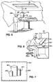
- Figure 5 shows an alternative embodiment of a rotating mirror apparatus for generating a 3D head tracked stereo image superimposed over a real object.
- Figure 6 illustrates a head tracked stereo display system that enables a viewer to perceive an arrangement of virtual objects and real objects such that real objects obscure virtual objects and virtual objects obscure real objects in a natural manner.
- Figure 7 shows an arrangement of virtual objects and real objects generated by the head tracked stereo display system of Figure 6.
-
- A method and apparatus is disclosed for generating complex 3D stereo images to enable a greater range of head movement for a viewer and to intermix light from virtual and real objects to enable a viewer to perceive a natural arrangement for the real and virtual objects. In the following description for purposes of explanation, specific applications, numbers, apparatus and configurations are set forth in order to provide a thorough understanding of the present invention. However, it will be apparent to one skilled in the art that the present invention may be practiced without these specific details. In other instances, well known systems are shown in diagrammatical or block diagram form in order not to obscure the present invention unnecessarily.
- Referring now to Figure 1, an exemplary computer based system for generating graphic images and responding to a user's input in accordance with the teachings of the present invention is illustrated. A
computer 10 comprised of three major components is shown. The first of these is an input/output (I/O)circuit 12 which is used to communicate information in appropriately structured form to and from other portions of thecomputer 10. In addition, thecomputer 10 includes a central processing unit (CPU) 14 coupled to the I/O circuit 12 and amemory 16. These elements are those typically found in most general purpose computers. Thecomputer 10 is intended to be representative of a broad category of computer systems. - A
magnetic disk 20 is shown coupled to the I/O circuit 12 to provide additional storage capability for thecomputer 10. As is well known, thedisk 20 may store other computer programs, characters, routines, images, etc., which may be accessed and executed by theCPU 14. It will be appreciated that additional devices may be coupled to thecomputer 10 for storing data such as magnetic tape drives, as well as networks which are in turn coupled to other computer systems. - A
CD ROM 20 is shown coupled to the I/O circuit 12 to provide an additional storage capability for distributing pre computed 3D stereo images in accordance with the teachings of the present invention. Also, anLCD panel controller 28 is shown coupled to the I/O circuit 12. TheLCD panel controller 28 receives bit map data from thecomputer 10 to control the transparency of the pixels of an LCD panel array. - A
motor control unit 30 is shown coupled to the I/O circuit 12. Themotor control unit 30 enables thecomputer 10 to control a servo motor. Alternatively, themotor control unit 30 enables thecomputer 10 to control a stepper motor. As will be described, the servo motor or stepper motor controlled by themotor control unit 30 enables thecomputer 10 to control positioning of a rotating mirror to generate virtual images. - A
raster display device 24 is shown coupled to the I/O circuit 12 and is used to display images generated by theCPU 14 in accordance to the teachings of the present invention. A wide variety of raster (or pixel mapped) display devices may be utilized asdisplay device 24. In the current embodiment, thedisplay device 24 comprises a stereo CRT. As is described more fully below, the display images generated by theCPU 14 through thedisplay device 24 are perceived by a viewer through a mirror. Therefore, theCPU 14 generates the display image so as to reverse the left and right positions of the pixels comprising the image. The mirror again reverses the left and right positions to enable the viewer to properly perceive the image. - A
keyboard 18 is shown coupled to the I/O circuit 12 and is used to input data and commands into thecomputer 10, as is well known. A pair of stereo shutteredglasses 120 is shown coupled to the I/O circuit 12. The stereo shutteredglasses 120 include a pair of embeddedultrasonic receivers 122 for receiving ultrasonic sound waves. The stereo shuttered glasses also have embedded an infrared controlled switch for controlling the shuttered lenses. - A 3D 6-
axis mouse 130 is shown coupled to the I/O circuit 12. The3D mouse 130 includes a set of threeultrasonic receivers 132 for receiving ultrasonic sound waves. The 3D positions of the3D mouse 130 and the shutteredglasses 120 are sensed by a 3D 6-axis head-tracker 140, which for one embodiment is mounted to thestereo CRT 24. The 3Dultrasonic tracking device 140 has embedded threeultrasonic transmitters 142 that generate the ultrasonic sound waves received by theultrasonic receivers - Referring now to Figure 2, one arrangement of major programs contained within the
memory 16 illustrated in Figure 1 is shown. In particular, there is shown aframe buffer 36, which serves as a pixel map of thedisplay 24. Theframe buffer 36 represents the video memory for thedisplay 24, wherein, each storage location in theframe buffer 36 corresponds to a left or right eye pixel on thestereo CRT 24. Thus, theframe buffer 36 comprises a two dimensional array of points having known coordinates corresponding to the pixels on thestereo CRT 24. Theframe buffer 36 is preferably arranged as a double buffer, such than an image can be accessed from one buffer while another image is being displayed from the other buffer. - The
memory 16 also comprises a variety of programs executed by theCPU 10 that implement functions according to the teaching of the present invention, as disclosed in this specification. Additionally, thememory 16 further comprises other programs for controlling or performing other well known functions and operation on computer systems. - For one embodiment, the viewer wears the stereo shuttered
glasses 120, and may manipulate the 3D 6-axis mouse 130. The 3D positions of the3D mouse 130 and the shutteredglasses 120 are sensed by a 3D 6-axis head-tracker 140. The travel time of the ultrasonic sound waves, between theultrasonic receivers ultrasonic transmitters 142, are used to triangulate the 3D positions of the shutteredglasses 120 and the3D mouse 130. The3D mouse 130 is used to manipulate a virtual image perceived by the viewer. - In a head tracked stereo display system, a stereo viewing display pipeline is specified by two 4x4 perspective viewing matrices (effectively, one monocular pipeline for each eye). These matrices implicitly contain information about the overall physical configuration of the viewing. Each resulting matrix includes a skew component.
- The physical configuration of the viewing is determined by the location of the display surface in 3-space and the dynamic location of the viewer's eyes. When these parameters are known, the viewing matrices are unique to within a scale factor. The viewing matrix for each eye corresponds to a pyramid having a tip at the viewer's eye and a base defined by the four corners of the display window within the display surface. The front and back dipping planes are parallel to the plane of the display surface, if the display surface is assumed to be perfectly flat.
- In the current embodiment, a computer graphics application specifies the relationship between physical coordinates and virtual coordinates (VC) by a matrix P. The relative position, orientation, and scale implied by the matrix P specify how the virtual and physical worlds are to be superimposed. (This scale factor is denoted g). The physical configuration of the stereo display device and the sensed real time location of the viewer's eye's contribute the remainder of the information necessary to the final 4x4 viewing matrices. The final 4x4 viewing matrices are used a parameters for the graphics rendering system implemented on the
computer 10. - To implement the teachings of the present invention, the
stereo CRT 24 is regarded as having a physical coordinate system registered to its display surface. This physical coordinate system is hereinafter referred to as display plate coordinates (DPC). - Referring to Figure 3, an example DPC coordinate system is illustrated. DPC has its origin at the lower left hand corner of the visible portion of a display surface of the
stereo CRT 24. The x axis proceeds horizontally to the right. The y axis proceeds vertically upwards. The z axis is normal to the virtual display surface, with positive coordinates out towards the viewer. - A window on the
virtual display surface 50 is defined by specifying a lower left hand and an upper right hand corner for the window as two DPC points L and H on the - The view matrix P for a single eye, expressed in column vector matrix format, that maps visible points in DPC into the extended unit cube of [-1 + 1] [-1 +1][-1+ 1], is as follows:

- The equations above apply to display devices such as the
stereo CRT 24, as well as projection stereo displays and stereo LCD panels. It should be noted that the intraocular distance, which is the distance between the viewer's eyes, is not directly represented in the view matrix P. - In a head-tracking display system, parallax on the display surface is not necessarily horizontal. If a viewer observes the display with eyes oriented vertically, then the parallax at the screen will be completely vertical. The amount of parallax at the screen is not consistent even for a given head distance and object location. When a viewers head is turned 30° to one side of the screen, the parallax at the screen surface is less than when the screen is squarely faced.
- In traditional computer graphics, the viewing projection point is referred to as the "eye point" or "viewpoint" and is intended to correspond to the viewer's eye. However, for the purposes of accurate display, the viewpoint location must be accurately identified physiologically. In general optical terms, the viewpoint of a lens system is the first nodal point.
- Accurate viewpoint location for the nodal points of the eye can be achieved by using eye tracking hardware to acquire information about the direction of gaze of each of the viewer's eyes. The combination of gaze information and head and eye location can be used to accurately locate the eye first nodal points in the DPC space. In addition, the gaze direction information can be used for identifying the region of the display surface space that corresponds to the fovial portion of the retina, and that deserves to be rendered with high spatial detail.
- Alternatively, errors due to uncertainty in eye first nodal point location can be minimized by anticipating the likely direction of the viewer's gaze. The likely direction of the viewer's gaze may be the center of the stereo window on the
virtual display surface 50. When the3D mouse 130 is employed, the viewer's gaze is likely to be in the direction of the "hot spot" of an interactive virtual image, as it is likely that the tightest accuracy requirement reflects "touching" the mouse to a virtual object. Choosing the direction of the viewer's gaze at the tip of the3D mouse 130 compensates for errors due to rotation of the eyes. Moreover, the image rendering software implemented on thecomputer 10 maintains DPC coordinates for the "hot spot" of the stereo image displayed on thevirtual display surface 50. - The current embodiment of the present invention employs an
ultrasonic tracking device 140 to acquire dynamic viewer head location and orientation within the DPC space. However, it should be noted that the present method does not depend on the tracking technology used. Head location and orientation data is used to derive the rotational centers of the viewer's eyes in real time using fixed vectors from the location of theultrasonic tracking device 140 to the viewer's eyes. - The intraocular distance of a viewer's head can very between individuals by as much as ±2 cm. In the current embodiment, the fixed vectors from the
ultrasonic tracking device 140 to the viewer's eyes are viewer specific in order to account for the intraocular distance of a given viewer. The fixed vectors also account for the registration of the head tracking device to the viewer's head. - In order for viewer to perceive computer generated objects as three dimensional physical objects, it is necessary to have a display frame rate sufficient for motion fusion. With stereo imagery there is the additional phenomenon of induced stereo movement, wherein objects displayed at a low frame rate appear to deform and twist. For further discussion, refer to Tyler, C.W., Induced Stereo movement, Vision Res.,
Vol 14, 609-613, Pergamon Press, 1974. - Figure 4a illustrates a
rotating mirror apparatus 51 for generating head tracked stereo images of virtual objects. Therotating mirror apparatus 51 enables a viewer to move around and perceive various perspective views of the virtual object or objects. Thestereo CRT 24 is embedded within a cylindrical shapedhousing 58. Thestereo CRT 24 is substantially centered along the axis of thecylindrical housing 58. Adisplay surface 55 of thestereo CRT 24 protrudes through the upper end of thecylindrical housing 58. Amirror 54 is coupled to arotating platform 56. For one embodiment, themirror 54 forms a 45 degree angle with respect to thedisplay surface 55 of thestereo CRT 24. - For one embodiment, a stepper motor (not shown) causes the rotating
platform 56 to revolve around thecenter axis 57 of thecylindrical housing 58. The stepper motor is coupled to themotor control unit 30. Themotor control unit 30 is coupled to receive control information from thecomputer 10. Thecomputer 10 causes the stepper motor to control the angular position of therotating platform 56, and thereby control the angular position of themirror 54. - Figure 4b illustrates the
rotating mirror apparatus 51 for generating a 3D head tracked stereo image of avirtual object 210. Theviewer 200 wears the shutteredglasses 120. The 3D position of the shutteredglasses 120 is sensed by theultrasonic tracking device 140. For one embodiment, theultrasonic tracking device 140 is mounted to therotating platform 56 because ultrasonic sound waves have limited range and require line of sight paths between theultrasonic tracking device 140 and the shutteredglasses 120. For an alternative embodiment, a tracing device having extended range and not requiring line of sight paths is mounted to thestereo CRT 24. - For one embodiment, the
computer 10 senses the travel time of the ultrasonic sound waves between theultrasonic transmitters 142 and themicrophones 122. Based upon the travel time, thecomputer 10 triangulates the 3D positions of the shutteredglasses 120. Thecomputer 10 corrects for the speed of sound given the air temperature and other factors to triangulate the 3D position of the shutteredglasses 120. - The
computer 10 tracks the 3D position of the head of theviewer 210 by tracking the 3D position of the shutteredglasses 120. As theviewer 200 moves around the rotating mirror apparatus, thecomputer 10 adjusts the rotational angle of themirror 54 such that themirror 54 maintains an angular position facing theviewer 200. - The
computer 10 and themotor control unit 30 implement a stabilizing control process that limits movement of therotating platform 56 to major head movements of theviewer 200. For one embodiment, thecomputer 10 and themotor control unit 30 implement dynamic Kalman filtering for stabilization control. - As the
computer 10 adjusts the rotational angle of themirror 54 to track movement of theviewer 200, the computer control effectively causes themirror 54 to follow the averaged location of the head of theviewer 200 over a short time interval. - An image rendering system implemented on the
computer 10 generates stereo images on thestereo CRT 24. The stereo images on thedisplay surface 55 of thestereo CRT 24 are reflected by themirror 54. Themirror 54 reflects the stereo images toward theviewer 200 wearing the shutteredglasses 120. Theviewer 200 perceives the reflected stereo images as avirtual object 210. Thevirtual object 210 appears transparent to theviewer 200 if themirror 54 is a half silvered mirror. If themirror 54 is a solid mirror, thevirtual object 210 appears solid to theviewer 200. - To the
viewer 200, thevirtual object 210 appears to be generated by a reflection of thestereo CRT 24 positioned behind themirror 54. As thecomputer 10 rotates themirror 54 to track the movements of theviewer 200, the reflection of thestereo CRT 24 moves within the DPC space accordingly. It will be appreciated that the reflection of thestereo CRT 24 appears to turn about thevertical axis 57 as themirror 54 rotates. - Figures 4c - 4d illustrate the changing positions of a
reflection 60 of thestereo CRT 24 as themirror 54 rotates in order to track the movements of theviewer 200. A top view of therotating mirror apparatus 51 is shown, including therotating platform 56, thestereo CRT 24, and therotating mirror 54. Also illustrated is a reflecteddisplay surface 50 of thestereo CRT 24 as perceived by theviewer 200 through themirror 54. - Figure 4c illustrates the position of the
reflection 60 of thestereo CRT 24 for an example position of theviewer 200 in relation to therotating mirror apparatus 51. Figure 4d illustrates the position of thereflection 60 of thestereo CRT 24 for another example position of theviewer 200 in relation to therotating mirror apparatus 51. - The
computer 10 determines the 3D position of thereflection 60 of thestereo CRT 24 from the rotational angle of therotating platform 56. Thecomputer 10 adjusts viewing matrices corresponding to the eyes of theviewer 200 in order to position the display surface of thestereo CRT 24 at the position of thedisplay surface 50 of thereflection 60 of thestereo CRT 24. Therefore, the DPC space is registered to thedisplay surface 50 of the reflection of thestereo CRT 24 as the virtual objects are mapped into the virtual space. Moreover, thecomputer 10 performs a top-bottom reversal of the coordinates of the stereo images on the display surface of thestereo CRT 24 to compensate for the reflection of the stereo images in themirror 54. - Figure 5 illustrates an alternative embodiment of a rotating mirror apparatus for generating a 3D head tracked stereo image superimposed over a real object. In the example shown, the rotating mirror apparatus enables a
viewer 220 to perceive a virtual image superimposed over asurgical patient 230. The virtual image is a 3D image of the surgical patient derived from a computer aided tomography (CAT) scan. - A
stereo CRT 70 is rotatably coupled to a ceiling mountedtrack 74. The ceiling mounted track enables translation of the position of thestereo CRT 70 along two dimensions parallel to the ceiling plane. A halfsilvered mirror 72 is mounted to thestereo CRT 70. For one embodiment, the half silveredmirror 72 forms a 45 degree angle with respect to the display surface of thestereo CRT 70. Thecomputer 10 actuates a stepper motor (not shown) to rotate thestereo CRT 70 and themirror 72 about an axis defined by thevertical shaft 75. - The
viewer 220 wears the stereo shutteredglasses 120. Theultrasonic tracking device 140 senses the 3D position of the shutteredglasses 120. For one embodiment, theultrasonic tracking device 140 is mounted to thestereo CRT 70. Thecomputer 10 tracks the 3D position of the head of theviewer 220 by sensing the 3D position of the shutteredglasses 120. As theviewer 220 moves, thecomputer 10 actuates the stepper motor to adjust the rotational angle of thestereo CRT 70 in order to maintain themirror 72 facing theviewer 220. - As the
computer 10 adjusts the rotational angle of thestereo CRT 70 and themirror 72 to track movement of theviewer 220, a computer filtered control effectively causes themirror 72 to follow the averaged location of the head of theviewer 220 over a short time interval. - An image rendering system implemented on the
computer 10 generates stereo images on thestereo CRT 70. The stereo images on the display surface of thestereo CRT 24 are reflected by themirror 72. Themirror 72 reflects the stereo images toward theviewer 220 wearing the shutteredglasses 120. Theviewer 220 perceives the reflected stereo images as a virtual image of a CAT scan. The virtual image appears transparent to theviewer 220 since themirror 72 is a half silvered mirror. - To the
viewer 220, the virtual image of the CAT scan appears to be generated by a reflection of thestereo CRT 70 positioned behind themirror 72. As thecomputer 10 rotates thestereo CRT 70 and themirror 72 to track the movements of theviewer 220, the reflection of thestereo CRT 70 moves within the DPC space accordingly. - The
computer 10 determines the 3D position of the reflection of thestereo CRT 70 from the rotational angle of thestereo CRT 70 around thevertical shaft 75 and from the x-y motion of the shaft. Thecomputer 10 adjusts viewing matrices corresponding to the eyes of theviewer 220 in order to position the display surface of thestereo CRT 70 at the position of the display surface of the reflection of thestereo CRT 70. The DPC space is registered to the display surface of the reflection of thestereo CRT 70 as the virtual image is mapped into the virtual space. Moreover, thecomputer 10 performs a top-bottom reversal of the coordinates of the stereo images on the display surface of thestereo CRT 70 to compensate for the reflection of the stereo images in themirror 72. - Figure 6 illustrates a head tracked stereo display system that enables a viewer to perceive an arrangement of virtual objects and real objects. The
stereo CRT 24 is shown mounted in an inverted position such that stereo images generated on thestereo CRT 24 are reflected by amirror 310. Themirror 310 is a half silvered mirror. Aviewer 300 wears the stereo shutteredglasses 120. The ultrasonic tracking device 140 (not shown) is mounted to thestereo CRT 24. - To the
viewer 300, the stereo images on thestereo CRT 24 appear to be generated by a reflection of thestereo CRT 24 positioned behind themirror 310. As a consequence, thecomputer 10 adjusts viewing matrices corresponding the eyes of theviewer 300 in order to position the display surface of thestereo CRT 24 at the position of the display surface of the reflection of thestereo CRT 24. Therefore, the DPC space is registered to the display surface of the reflection of thestereo CRT 24 as the virtual objects are mapped into the virtual space. Also, thecomputer 10 performs a top-bottom reversal of the coordinates of the stereo images on the display surface of thestereo CRT 24 to compensate for the reflection of the stereo images in themirror 310. - The
computer 10 uses theultrasonic tracking device 140 to sense the 3D position of the head of theviewer 300. Thereafter, the image rendering system on thecomputer 10 generates stereo images on thestereo CRT 24 to render the virtual objects behind the halfsilvered mirror 310. Theviewer 300 wearing the stereo shutteredglasses 120 perceives the reflected stereo images as one or more virtual objects positioned behind the halfsilvered mirror 310. The halt silveredmirror 310 also enables theviewer 300 to perceive areal object 330 positioned behind the halfsilvered mirror 310. - The
computer 10 maintains a physical object data base indicating the 3D geometry of thereal object 330, and indicating the physical location of thereal object 330. Thereal object 330 is modeled as a black object, i.e. no color, in the physical object data base. The image rendering system of thecomputer 10 renders thephysical object 330 in the virtual space in order to generate z buffer values for thephysical object 330. - If a physical object is positioned within the DPC space in front of a virtual object from the point of view of the
viewer 300, the z buffer of the image rendering system of thecomputer 10 causes no light to be emitted from thestereo CRT 24 for portions of the virtual object obscured by the real object. In this manner, theviewer 300 perceives the virtual object to be behind the real object. - On the other hand, if a physical object is positioned within the DPC space behind a virtual object from the point of view of the
viewer 300, anLCD array panel 320 is employed to obscure portions of the physical object that are behind the virtual object. TheLCD array panel 320 is positioned over the halfsilvered mirror 310. Thecomputer 10 controls the array of LCD pixels comprising theLCD array panel 320. Thecomputer 10 causes theLCD array panel 320 to selectively block light from passing through the halfsilvered mirror 320 to theviewer 300. Thecomputer 10 causes theLCD array panel 320 to block portions of the physical object that are behind the virtual object. As a result, theviewer 300 perceives the virtual object to be in front of the real object. - Figure 7 shows an arrangement of virtual objects and real objects generated by the head tracked stereo display system of Figure 6. A
virtual object 350, areal object 360, and avirtual object 370 are perceived by theviewer 300. Thecomputer 10 generates thevirtual objects 250 and 370 by generating stereo images on thestereo CRT 24, which are reflected by the halfsilvered mirror 310 as previously discussed. Thereal object 360 is positioned behind the halfsilvered mirror 310 in relation to theviewer 300. Light reflected from thereal object 360 passes through the halfsilvered mirror 310, and is perceived by theviewer 300. Thecomputer 10 causes theLCD array panel 320 to selectively block light reflected from thereal object 360. - The physical object data base indicates the 3D geometry of the
real object 360, and indicates the physical location in the DPC space of thereal object 360. Thereal object 360 is modeled as a black object in the physical object data base. The image rendering system of thecomputer 10 renders thephysical object 360 in the virtual space in order to generate z buffer values for thephysical object 360. - The
real object 360 is positioned within the DPC space in front of thevirtual object 370 from the point of view of theviewer 300. As illustrated, the z buffer of the image rendering system of thecomputer 10 causes no light to be emitted from thestereo CRT 24 for portions of thevirtual object 370 obscured by thereal object 360. Thus, theviewer 300 perceives thevirtual object 370 to be positioned behind thereal object 360. - The
real object 360 is positioned within the DPC space behind thevirtual object 350 from the point of view of theviewer 300. As illustrated, thecomputer 10 causes the pixels ofLCD array panel 320 corresponding to portions of thephysical object 360 that are behind thevirtual object 350 to block light from thephysical object 360. Light from the stereo images on thestereo CRT 24 is reflected by the halfsilvered mirror 310. As a result, theviewer 300 perceives thevirtual object 350 to be positioned in front of thereal object 360. - The
real object 360 positioned behind themirror 310 appears to be in front of thevirtual object 370 if a model of thereal object 360 has been rendered within the DPC space at the proper distance, size, and orientation, with a completely black color. Rendering of thereal object 360 in the DPC space causes no light to be emitted from the stereo CRT 24 (beyond the minimum black level). As a consequence, the only changing light coming from the portion of the viewers gaze corresponding to thereal object 360 is the light from thereal object 360. - The
virtual object 350 appears to be in front of thereal object 360, but only as a transparent object unable to occlude the images of thereal object 360. The range of transparency is limited by the configuration of themirror 310. Thevirtual object 350 exhibits the least amount of transparency when rendered at full intensity. The degree of transparency depends upon the percentage of reflected versus transmitted light from themirror 310. Thevirtual object 350 exhibits higher degrees of transparency for any particular mirror when rendered at a lower intensity. - The
LCD array panel 320 enables thecomputer 10 to control the amounts of transmitted versus reflected light perceived by theviewer 300. TheLCD array panel 320 is positioned on the far side of the halfsilvered mirror 310 from theviewer 300. TheLCD array panel 320 controls the amount of directly transmitted light from thereal object 360 to theviewer 300. TheLCD array panel 320 controls transfer of light on a per pixel basis. - The
LCD array panel 320 controls light transfer in two modes. In binary mode, theLCD array panel 320 transfers all or none of the light fromreal object 360 on a per pixel basis. In "alpha" mode, a percentage of light from thereal object 360 is transferred. The percentage of light transferred is set to a fractional amount per pixel (within the LCD's dynamistic range, update rates, etc.) The binary mode is an extreme version of the alpha mode in which the control value "alpha" can take on only the values of 0 or 1. - In binary mode, the
virtual object 350 can occlude thereal object 360. To accomplish this, an alpha frame buffer storage bit is maintained by thecomputer 10 for each pixel of theLCD array panel 320. When rendering thevirtual object 350, the alpha values corresponding to thevirtual object 350 are set to 1 (i.e. no physical object light passes through the LCD array panel 320). The alpha values corresponding to the "black" model of thereal object 360 are set to 0. - When z-buffering is performed by the
computer 10 for thevirtual object 350 and thereal object 360, the closest object type (real or virtual) at each pixel will set the alpha bit to the proper value as outlined above. The alpha image is displayed on theLCD array panel 320, causing the proper light valving effects. A form of transparency is rendered for both real and virtual objects by "screen-door" transparency methods. - In alpha mode, transparency is performed by controlling the amount of light passing through each pixel of the
LCD array panel 320. Thecomputer 10 implements a rendering method that sets the appropriate fractional alpha value in the frame buffer to control the transparency of theLCD array panel 320. The alpha mode enables theviewer 300 to perceive a transparentvirtual object 350 in front of the real object 360 (solid or transparent). The alpha mode also enables theviewer 300 to perceive a transparent real object 360 (like a glass) in front of the virtual object 370 (solid or transparent). - The value chosen for alpha may be a constant for a given object, or a complex function computed according to the real or simulated optical properties of the real or virtual object, respectively. Complex effects, such as the
viewer 300 perceiving a magnified virtual object through a real magnifying glass can be performed. Alternatively, the real objects can be digitized and transferred to thecomputer 10, such that thecomputer 10 performs the appropriate optical simulations and effects. Thecomputer 10 completely replaces a physical object with a doppenganger virtual object. Thus, in the apparatus of Figure 6, some physical objects have pure black virtual counterparts, while some physical objects are replaced with non-black virtual copies by setting the corresponding alpha values to 1. - In the foregoing specification, the invention has been described with reference to specific exemplary embodiments thereof. It will, however, be evident that various modifications and changes may be made thereto without departing from the scope of the invention as set forth in the appended claims. The specification and drawings are accordingly to be regarded as illustrative rather than restrictive.
Claims (12)
- An apparatus for generating an accurate stereo three dimensional image intermixed with a real object, comprising:display device having a display surface for generating stereo images rendered by a computer means, the stereo images corresponding to a virtual coordinate space, the computer means generating a z buffer indicating three dimensional positioning for the real object and the virtual object within the virtual coordinate space;reflector means positioned to transmit the stereo images to the eyes of a viewer, the reflector means further transmitting light reflected from the real object to the eyes of the viewer;means for selectively blocking transmission of the light reflected from the real object to the eyes of the viewer under control of the computer means.
- The apparatus of claim 1, wherein the display device comprises a stereo CRT.
- The apparatus of claim 1, wherein the reflector means comprises a half silvered mirror, such that the mirror forms a substantially forty five degree angle in relation to the display surface of the display device.
- The apparatus of claim 1, wherein the means for selectively blocking transmission of the light reflected from the real object comprises an LCD array panel positioned adjacent to the reflector means opposite the viewer.
- The apparatus of claim 1, wherein the means for selectively blocking transmission of the light blocks transmission of light on a per pixel basis according to a plurality of alpha values determined by the computer means, wherein each alpha value corresponds to a pixel.
- The apparatus of claim 5, wherein the computer means determines the alpha values by rending the real object and the virtual object in the virtual coordinate space, and by performing z-buffering on the rendered real and virtual objects.
- A method for generating an accurate stereo three dimensional image intermixed with a real object, comprising the steps of:generating stereo images rendered by a computer means on a display surface of a display device, the stereo images corresponding to a virtual coordinate space, the computer means generating a z buffer indicating three dimensional positioning for the real object and the virtual object within the virtual coordinate space;reflecting the stereo images to the eyes of a viewer, and transmitting light reflected from the real object to the eyes of the viewer;selectively blocking transmission of the light reflected from the real object to the eyes of the viewer under control of the computer means.
- The method of claim 7, wherein the display device comprises a stereo CRT.
- The method of claim 7, wherein the steps of reflecting the stereo images to the eyes of a viewer, and transmitting light reflected from the real object comprises the step of positioning a half silvered mirror, such that the mirror forms a substantially forty five degree angle in relation to the display surface of the display device.
- The method of clam 7, wherein the step of selectively blocking transmission of the light reflected from the real object comprises the step of positioning an LCD array panel adjacent to the reflector means opposite the viewer.
- The method of claim 7, wherein the step of selectively blocking transmission of the light reflected from the real object comprises the step of selectively blocking transmission of light from the real object on a per pixel basis according to a plurality of alpha values determined by the computer means, wherein each alpha value corresponds to a pixel.
- The method of claim 11, wherein the computer means determines the alpha values by rending the real object and the virtual object in the virtual coordinate space, and by performing z-buffering on the rendered real and virtual objects.
Applications Claiming Priority (3)
| Application Number | Priority Date | Filing Date | Title |
|---|---|---|---|
| US08/004,706 US5394202A (en) | 1993-01-14 | 1993-01-14 | Method and apparatus for generating high resolution 3D images in a head tracked stereo display system |
| US4706 | 1993-01-14 | ||
| EP94300146A EP0607000B1 (en) | 1993-01-14 | 1994-01-10 | Method and apparatus for generating high resolution 3D images in a head tracked stereo display system |
Related Parent Applications (1)
| Application Number | Title | Priority Date | Filing Date |
|---|---|---|---|
| EP94300146A Division EP0607000B1 (en) | 1993-01-14 | 1994-01-10 | Method and apparatus for generating high resolution 3D images in a head tracked stereo display system |
Publications (2)
| Publication Number | Publication Date |
|---|---|
| EP0996093A1 true EP0996093A1 (en) | 2000-04-26 |
| EP0996093B1 EP0996093B1 (en) | 2003-07-30 |
Family
ID=21712123
Family Applications (2)
| Application Number | Title | Priority Date | Filing Date |
|---|---|---|---|
| EP94300146A Expired - Lifetime EP0607000B1 (en) | 1993-01-14 | 1994-01-10 | Method and apparatus for generating high resolution 3D images in a head tracked stereo display system |
| EP99115009A Expired - Lifetime EP0996093B1 (en) | 1993-01-14 | 1994-01-10 | Method and apparatus for generating high resolution 3D images in a head tracked stereo display system |
Family Applications Before (1)
| Application Number | Title | Priority Date | Filing Date |
|---|---|---|---|
| EP94300146A Expired - Lifetime EP0607000B1 (en) | 1993-01-14 | 1994-01-10 | Method and apparatus for generating high resolution 3D images in a head tracked stereo display system |
Country Status (5)
| Country | Link |
|---|---|
| US (1) | US5394202A (en) |
| EP (2) | EP0607000B1 (en) |
| JP (1) | JP3575622B2 (en) |
| KR (2) | KR100327874B1 (en) |
| DE (2) | DE69432994T2 (en) |
Cited By (3)
| Publication number | Priority date | Publication date | Assignee | Title |
|---|---|---|---|---|
| US7090129B2 (en) | 2001-11-30 | 2006-08-15 | Olympus Corporation | Code reader and card type recording medium |
| GB2481366A (en) * | 2010-06-03 | 2011-12-28 | Sony Comp Entertainment Europe | 3D interactive display and pointer control |
| CN103631024A (en) * | 2013-11-29 | 2014-03-12 | 北京赢康科技开发有限公司 | Stereo display system |
Families Citing this family (55)
| Publication number | Priority date | Publication date | Assignee | Title |
|---|---|---|---|---|
| EP0702494B1 (en) * | 1994-09-19 | 2001-12-05 | Matsushita Electric Industrial Co., Ltd. | Three-dimensional image display apparatus |
| AUPN003894A0 (en) * | 1994-12-13 | 1995-01-12 | Xenotech Research Pty Ltd | Head tracking system for stereoscopic display apparatus |
| US6005607A (en) | 1995-06-29 | 1999-12-21 | Matsushita Electric Industrial Co., Ltd. | Stereoscopic computer graphics image generating apparatus and stereoscopic TV apparatus |
| US5831638A (en) * | 1996-03-08 | 1998-11-03 | International Business Machines Corporation | Graphics display system and method for providing internally timed time-varying properties of display attributes |
| US6480204B1 (en) * | 1996-04-30 | 2002-11-12 | Sun Microsystems, Inc. | Transparent sunpad for home shopping |
| AUPO024696A0 (en) | 1996-06-04 | 1996-06-27 | Xenotech Research Pty Ltd | Video display system |
| US6302542B1 (en) * | 1996-08-23 | 2001-10-16 | Che-Chih Tsao | Moving screen projection technique for volumetric three-dimensional display |
| JP3651204B2 (en) * | 1996-12-18 | 2005-05-25 | トヨタ自動車株式会社 | Stereoscopic image display device, stereoscopic image display method, and recording medium |
| US5781229A (en) * | 1997-02-18 | 1998-07-14 | Mcdonnell Douglas Corporation | Multi-viewer three dimensional (3-D) virtual display system and operating method therefor |
| US6394557B2 (en) | 1998-05-15 | 2002-05-28 | Intel Corporation | Method and apparatus for tracking an object using a continuously adapting mean shift |
| SG77682A1 (en) * | 1998-05-21 | 2001-01-16 | Univ Singapore | A display system |
| SG87768A1 (en) * | 1998-05-21 | 2002-04-16 | Univ Singapore | Compact reach-in display system for two-handed user interaction with virtual objects |
| WO2000007059A1 (en) * | 1998-07-29 | 2000-02-10 | Spodek Joshua D | Apparatus for displaying images to viewers in motion |
| JP4100531B2 (en) * | 1998-08-11 | 2008-06-11 | 株式会社東京大学Tlo | Information presentation method and apparatus |
| US6538649B2 (en) | 1998-12-01 | 2003-03-25 | Intel Corporation | Computer vision control variable transformation |
| US6396476B1 (en) | 1998-12-01 | 2002-05-28 | Intel Corporation | Synthesizing computer input events |
| US6363160B1 (en) | 1999-01-22 | 2002-03-26 | Intel Corporation | Interface using pattern recognition and tracking |
| US6747665B1 (en) | 1999-05-10 | 2004-06-08 | Ge Medical Systems Global Technology Company, Llc | Semi-transparent medical image overlays |
| US6554431B1 (en) * | 1999-06-10 | 2003-04-29 | Sony Corporation | Method and apparatus for image projection, and apparatus controlling image projection |
| US6647131B1 (en) | 1999-08-27 | 2003-11-11 | Intel Corporation | Motion detection using normal optical flow |
| US7142281B2 (en) | 2000-06-02 | 2006-11-28 | Georae Ltd. | Method and system for providing a three dimensional image |
| KR20010113117A (en) * | 2000-06-16 | 2001-12-28 | 최재학 | Three dimensional image display apparatus |
| US6931596B2 (en) | 2001-03-05 | 2005-08-16 | Koninklijke Philips Electronics N.V. | Automatic positioning of display depending upon the viewer's location |
| WO2002100285A1 (en) * | 2001-06-13 | 2002-12-19 | Volume Interactions Pte Ltd | A guide system and a probe therefor |
| EP1395194B1 (en) * | 2001-06-13 | 2007-08-29 | Volume Interactions Pte. Ltd. | A guide system |
| US7190825B2 (en) | 2001-08-17 | 2007-03-13 | Geo-Rae Co., Ltd. | Portable communication device for stereoscopic image display and transmission |
| US6646072B2 (en) * | 2002-01-23 | 2003-11-11 | Equistar Chemicals, Lp | Process for making polyolefin compositions containing exfoliated clay |
| US20030222977A1 (en) * | 2002-06-03 | 2003-12-04 | Kazutora Yoshino | Intelligent system and 3D virtual object generator |
| JP2004199496A (en) * | 2002-12-19 | 2004-07-15 | Sony Corp | Information processor and method, and program |
| US20050237622A1 (en) * | 2003-07-28 | 2005-10-27 | Kazutora Yoshino | Color 3D image display |
| DE10335644B9 (en) * | 2003-08-04 | 2006-06-01 | Carl Zeiss | microscopy system |
| US20060192869A1 (en) * | 2005-02-28 | 2006-08-31 | Kazutora Yoshino | Multi-dimensional input, transfer, optional memory, and output method |
| JP4522129B2 (en) * | 2004-03-31 | 2010-08-11 | キヤノン株式会社 | Image processing method and image processing apparatus |
| US20060158455A1 (en) * | 2005-01-18 | 2006-07-20 | Kazutora Yoshino | Real clear 3D multi-user communicator |
| JP2006276391A (en) * | 2005-03-29 | 2006-10-12 | Yasui & Co | Enlarging observation system |
| JP4274154B2 (en) * | 2005-05-31 | 2009-06-03 | 富士ゼロックス株式会社 | 3D display device |
| KR100913173B1 (en) * | 2005-07-05 | 2009-08-19 | 삼성모바일디스플레이주식회사 | 3 dimension graphic processor and autostereoscopic display device using the same |
| KR100932977B1 (en) | 2005-07-05 | 2009-12-21 | 삼성모바일디스플레이주식회사 | Stereoscopic video display |
| EP1750460A1 (en) | 2005-08-05 | 2007-02-07 | Samsung SDI Co., Ltd. | 3D graphics processor and autostereoscopic display device using the same |
| JP4111231B2 (en) * | 2006-07-14 | 2008-07-02 | 富士ゼロックス株式会社 | 3D display system |
| JP4764305B2 (en) * | 2006-10-02 | 2011-08-31 | 株式会社東芝 | Stereoscopic image generating apparatus, method and program |
| US20100020254A1 (en) * | 2008-07-23 | 2010-01-28 | Zheng Jason Geng | Multi-panel virtual image display |
| TWI370418B (en) * | 2008-10-27 | 2012-08-11 | Ind Tech Res Inst | Computer system and controlling method thereof |
| WO2010112062A1 (en) * | 2009-03-30 | 2010-10-07 | Renault S.A.S. | Device for projecting a virtual object onto a screen |
| TWM368805U (en) * | 2009-07-03 | 2009-11-11 | Teng Luo Technology Co Ltd | Device for displaying 3D images |
| US9189885B2 (en) * | 2009-09-16 | 2015-11-17 | Knorr-Bremse Systeme Fur Schienenfahrzeuge Gmbh | Visual presentation system |
| US8704879B1 (en) | 2010-08-31 | 2014-04-22 | Nintendo Co., Ltd. | Eye tracking enabling 3D viewing on conventional 2D display |
| FR2976681B1 (en) * | 2011-06-17 | 2013-07-12 | Inst Nat Rech Inf Automat | SYSTEM FOR COLOCATING A TOUCH SCREEN AND A VIRTUAL OBJECT AND DEVICE FOR HANDLING VIRTUAL OBJECTS USING SUCH A SYSTEM |
| DE102011112618A1 (en) * | 2011-09-08 | 2013-03-14 | Eads Deutschland Gmbh | Interaction with a three-dimensional virtual scenario |
| US9265458B2 (en) | 2012-12-04 | 2016-02-23 | Sync-Think, Inc. | Application of smooth pursuit cognitive testing paradigms to clinical drug development |
| US9380976B2 (en) | 2013-03-11 | 2016-07-05 | Sync-Think, Inc. | Optical neuroinformatics |
| JP6138566B2 (en) * | 2013-04-24 | 2017-05-31 | 川崎重工業株式会社 | Component mounting work support system and component mounting method |
| FI20145396A (en) | 2014-04-29 | 2015-10-30 | Satavision Oy | Virtual display |
| US10520728B2 (en) * | 2017-10-17 | 2019-12-31 | Visteon Global Technologies, Inc. | Embedded optimization algorithm of parameters to drive deployment mechanism for displays |
| EP3770670B1 (en) * | 2018-03-23 | 2023-10-11 | Sony Semiconductor Solutions Corporation | Display device |
Citations (1)
| Publication number | Priority date | Publication date | Assignee | Title |
|---|---|---|---|---|
| US4722056A (en) * | 1986-02-18 | 1988-01-26 | Trustees Of Dartmouth College | Reference display systems for superimposing a tomagraphic image onto the focal plane of an operating microscope |
Family Cites Families (7)
| Publication number | Priority date | Publication date | Assignee | Title |
|---|---|---|---|---|
| US4649425A (en) * | 1983-07-25 | 1987-03-10 | Pund Marvin L | Stereoscopic display |
| US4634384A (en) * | 1984-02-02 | 1987-01-06 | General Electric Company | Head and/or eye tracked optically blended display system |
| US4639081A (en) * | 1985-08-15 | 1987-01-27 | Kabushiki Kaisha Toshiba | Gimballed three-dimensional display system |
| US4922336A (en) * | 1989-09-11 | 1990-05-01 | Eastman Kodak Company | Three dimensional display system |
| JPH06502509A (en) * | 1990-10-22 | 1994-03-17 | ロジテク,インコーポレイテッド | Ultrasonic positioning method and device |
| DE4207284C2 (en) * | 1992-03-07 | 1996-08-22 | Stefan Reich | Spatial image presentation |
| US5287437A (en) * | 1992-06-02 | 1994-02-15 | Sun Microsystems, Inc. | Method and apparatus for head tracked display of precomputed stereo images |
-
1993
- 1993-01-14 US US08/004,706 patent/US5394202A/en not_active Expired - Lifetime
-
1994
- 1994-01-10 EP EP94300146A patent/EP0607000B1/en not_active Expired - Lifetime
- 1994-01-10 DE DE69432994T patent/DE69432994T2/en not_active Expired - Fee Related
- 1994-01-10 EP EP99115009A patent/EP0996093B1/en not_active Expired - Lifetime
- 1994-01-10 DE DE69425913T patent/DE69425913T2/en not_active Expired - Fee Related
- 1994-01-14 JP JP01499194A patent/JP3575622B2/en not_active Expired - Lifetime
- 1994-01-14 KR KR1019940000602A patent/KR100327874B1/en not_active IP Right Cessation
-
2001
- 2001-03-17 KR KR1020010013905A patent/KR100311066B1/en not_active IP Right Cessation
Patent Citations (1)
| Publication number | Priority date | Publication date | Assignee | Title |
|---|---|---|---|---|
| US4722056A (en) * | 1986-02-18 | 1988-01-26 | Trustees Of Dartmouth College | Reference display systems for superimposing a tomagraphic image onto the focal plane of an operating microscope |
Non-Patent Citations (2)
| Title |
|---|
| BAJURA M ET AL: "MERGING VIRTUAL OBJECTS WITH THE REAL WORLD: SEEING ULTRASOUND IMAGERY WITHIN THE PATIENT", COMPUTER GRAPHICS PROCEEDINGS. ANNUAL CONFERENCE SERIES. SIGGRAPH,XX,XX, vol. 26, no. 2, 1 July 1992 (1992-07-01), pages 203 - 210, XP002045387 * |
| FRIETS E M ET AL: "A FRAMELESS STEREOTAXIC OPERATING MICROSCOPE FOR NEUROSURGERY", IEEE TRANSACTIONS ON BIOMEDICAL ENGINEERING,US,IEEE INC. NEW YORK, vol. 36, no. 6, 1 June 1989 (1989-06-01), pages 608 - 617, XP000099027, ISSN: 0018-9294 * |
Cited By (4)
| Publication number | Priority date | Publication date | Assignee | Title |
|---|---|---|---|---|
| US7090129B2 (en) | 2001-11-30 | 2006-08-15 | Olympus Corporation | Code reader and card type recording medium |
| GB2481366A (en) * | 2010-06-03 | 2011-12-28 | Sony Comp Entertainment Europe | 3D interactive display and pointer control |
| GB2481366B (en) * | 2010-06-03 | 2014-05-28 | Sony Comp Entertainment Europe | Entertainment device and entertainment methods |
| CN103631024A (en) * | 2013-11-29 | 2014-03-12 | 北京赢康科技开发有限公司 | Stereo display system |
Also Published As
| Publication number | Publication date |
|---|---|
| US5394202A (en) | 1995-02-28 |
| EP0996093B1 (en) | 2003-07-30 |
| DE69425913T2 (en) | 2001-04-26 |
| KR100327874B1 (en) | 2002-06-20 |
| JPH06317762A (en) | 1994-11-15 |
| EP0607000A3 (en) | 1995-11-15 |
| JP3575622B2 (en) | 2004-10-13 |
| DE69432994D1 (en) | 2003-09-04 |
| KR940018769A (en) | 1994-08-18 |
| EP0607000A2 (en) | 1994-07-20 |
| EP0607000B1 (en) | 2000-09-20 |
| DE69432994T2 (en) | 2004-04-22 |
| KR100311066B1 (en) | 2001-10-18 |
| DE69425913D1 (en) | 2000-10-26 |
Similar Documents
| Publication | Publication Date | Title |
|---|---|---|
| EP0607000B1 (en) | Method and apparatus for generating high resolution 3D images in a head tracked stereo display system | |
| US5446834A (en) | Method and apparatus for high resolution virtual reality systems using head tracked display | |
| US5287437A (en) | Method and apparatus for head tracked display of precomputed stereo images | |
| Deering | High resolution virtual reality | |
| US4984179A (en) | Method and apparatus for the perception of computer-generated imagery | |
| US11182958B2 (en) | Infinite far-field depth perception for near-field objects in virtual environments | |
| Arthur et al. | Evaluating 3d task performance for fish tank virtual worlds | |
| US20160267720A1 (en) | Pleasant and Realistic Virtual/Augmented/Mixed Reality Experience | |
| US5742331A (en) | Three-dimensional image display apparatus | |
| US8704882B2 (en) | Simulated head mounted display system and method | |
| US10397539B2 (en) | Compensating 3D stereoscopic imagery | |
| US5751927A (en) | Method and apparatus for producing three dimensional displays on a two dimensional surface | |
| US20040135744A1 (en) | Virtual showcases | |
| US20210283496A1 (en) | Realistic Virtual/Augmented/Mixed Reality Viewing and Interactions | |
| CN109979016B (en) | Method for displaying light field image by AR (augmented reality) equipment, AR equipment and storage medium | |
| Ware | Dynamic stereo displays | |
| US11353953B2 (en) | Method of modifying an image on a computational device | |
| EP0928117A2 (en) | Method and apparatus for providing volumetric projection | |
| WO2002015110A1 (en) | Virtual showcases | |
| TW202205851A (en) | Light transmitting display system, image output method thereof and processing device thereof | |
| Kenyon et al. | Visual requirements for virtual‐environment generation | |
| JPH06337756A (en) | Three-dimensional position specifying method and virtual space stereoscopic device | |
| Akka | Utilizing 6D head-tracking data for stereoscopic computer-graphics perspective transformations | |
| Merritt | Visual-motor realism in 3D teleoperator display systems | |
| Arthur | 3D task performance using head-coupled stereo displays |
Legal Events
| Date | Code | Title | Description |
|---|---|---|---|
| PUAI | Public reference made under article 153(3) epc to a published international application that has entered the european phase |
Free format text: ORIGINAL CODE: 0009012 |
|
| AC | Divisional application: reference to earlier application |
Ref document number: 607000 Country of ref document: EP |
|
| AK | Designated contracting states |
Kind code of ref document: A1 Designated state(s): DE FR GB NL |
|
| 17P | Request for examination filed |
Effective date: 20001007 |
|
| AKX | Designation fees paid |
Free format text: DE FR GB NL |
|
| GRAH | Despatch of communication of intention to grant a patent |
Free format text: ORIGINAL CODE: EPIDOS IGRA |
|
| GRAH | Despatch of communication of intention to grant a patent |
Free format text: ORIGINAL CODE: EPIDOS IGRA |
|
| GRAA | (expected) grant |
Free format text: ORIGINAL CODE: 0009210 |
|
| AC | Divisional application: reference to earlier application |
Ref document number: 0607000 Country of ref document: EP Kind code of ref document: P |
|
| AK | Designated contracting states |
Designated state(s): DE FR GB NL |
|
| PG25 | Lapsed in a contracting state [announced via postgrant information from national office to epo] |
Ref country code: NL Free format text: LAPSE BECAUSE OF FAILURE TO SUBMIT A TRANSLATION OF THE DESCRIPTION OR TO PAY THE FEE WITHIN THE PRESCRIBED TIME-LIMIT Effective date: 20030730 |
|
| REG | Reference to a national code |
Ref country code: GB Ref legal event code: FG4D |
|
| REF | Corresponds to: |
Ref document number: 69432994 Country of ref document: DE Date of ref document: 20030904 Kind code of ref document: P |
|
| NLV1 | Nl: lapsed or annulled due to failure to fulfill the requirements of art. 29p and 29m of the patents act | ||
| PGFP | Annual fee paid to national office [announced via postgrant information from national office to epo] |
Ref country code: FR Payment date: 20040108 Year of fee payment: 11 |
|
| PGFP | Annual fee paid to national office [announced via postgrant information from national office to epo] |
Ref country code: DE Payment date: 20040122 Year of fee payment: 11 |
|
| ET | Fr: translation filed | ||
| PLBE | No opposition filed within time limit |
Free format text: ORIGINAL CODE: 0009261 |
|
| STAA | Information on the status of an ep patent application or granted ep patent |
Free format text: STATUS: NO OPPOSITION FILED WITHIN TIME LIMIT |
|
| 26N | No opposition filed |
Effective date: 20040504 |
|
| PG25 | Lapsed in a contracting state [announced via postgrant information from national office to epo] |
Ref country code: DE Free format text: LAPSE BECAUSE OF NON-PAYMENT OF DUE FEES Effective date: 20050802 |
|
| PG25 | Lapsed in a contracting state [announced via postgrant information from national office to epo] |
Ref country code: FR Free format text: LAPSE BECAUSE OF NON-PAYMENT OF DUE FEES Effective date: 20050930 |
|
| REG | Reference to a national code |
Ref country code: FR Ref legal event code: ST |
|
| PGFP | Annual fee paid to national office [announced via postgrant information from national office to epo] |
Ref country code: GB Payment date: 20070110 Year of fee payment: 14 |
|
| GBPC | Gb: european patent ceased through non-payment of renewal fee |
Effective date: 20080110 |
|
| PG25 | Lapsed in a contracting state [announced via postgrant information from national office to epo] |
Ref country code: GB Free format text: LAPSE BECAUSE OF NON-PAYMENT OF DUE FEES Effective date: 20080110 |