EP0995895A2 - Fan shroud and air intake arrangement - Google Patents
Fan shroud and air intake arrangement Download PDFInfo
- Publication number
- EP0995895A2 EP0995895A2 EP99308188A EP99308188A EP0995895A2 EP 0995895 A2 EP0995895 A2 EP 0995895A2 EP 99308188 A EP99308188 A EP 99308188A EP 99308188 A EP99308188 A EP 99308188A EP 0995895 A2 EP0995895 A2 EP 0995895A2
- Authority
- EP
- European Patent Office
- Prior art keywords
- air
- combination
- air intake
- engine
- intake
- Prior art date
- Legal status (The legal status is an assumption and is not a legal conclusion. Google has not performed a legal analysis and makes no representation as to the accuracy of the status listed.)
- Granted
Links
Images
Classifications
-
- F—MECHANICAL ENGINEERING; LIGHTING; HEATING; WEAPONS; BLASTING
- F02—COMBUSTION ENGINES; HOT-GAS OR COMBUSTION-PRODUCT ENGINE PLANTS
- F02M—SUPPLYING COMBUSTION ENGINES IN GENERAL WITH COMBUSTIBLE MIXTURES OR CONSTITUENTS THEREOF
- F02M35/00—Combustion-air cleaners, air intakes, intake silencers, or induction systems specially adapted for, or arranged on, internal-combustion engines
- F02M35/10—Air intakes; Induction systems
- F02M35/10006—Air intakes; Induction systems characterised by the position of elements of the air intake system in direction of the air intake flow, i.e. between ambient air inlet and supply to the combustion chamber
- F02M35/10013—Means upstream of the air filter; Connection to the ambient air
-
- F—MECHANICAL ENGINEERING; LIGHTING; HEATING; WEAPONS; BLASTING
- F01—MACHINES OR ENGINES IN GENERAL; ENGINE PLANTS IN GENERAL; STEAM ENGINES
- F01P—COOLING OF MACHINES OR ENGINES IN GENERAL; COOLING OF INTERNAL-COMBUSTION ENGINES
- F01P11/00—Component parts, details, or accessories not provided for in, or of interest apart from, groups F01P1/00 - F01P9/00
- F01P11/10—Guiding or ducting cooling-air, to, or from, liquid-to-air heat exchangers
-
- F—MECHANICAL ENGINEERING; LIGHTING; HEATING; WEAPONS; BLASTING
- F02—COMBUSTION ENGINES; HOT-GAS OR COMBUSTION-PRODUCT ENGINE PLANTS
- F02M—SUPPLYING COMBUSTION ENGINES IN GENERAL WITH COMBUSTIBLE MIXTURES OR CONSTITUENTS THEREOF
- F02M35/00—Combustion-air cleaners, air intakes, intake silencers, or induction systems specially adapted for, or arranged on, internal-combustion engines
- F02M35/02—Air cleaners
- F02M35/04—Air cleaners specially arranged with respect to engine, to intake system or specially adapted to vehicle; Mounting thereon ; Combinations with other devices
- F02M35/06—Air cleaners specially arranged with respect to engine, to intake system or specially adapted to vehicle; Mounting thereon ; Combinations with other devices combined or associated with engine's cooling blower or fan, or with flywheel
-
- F—MECHANICAL ENGINEERING; LIGHTING; HEATING; WEAPONS; BLASTING
- F02—COMBUSTION ENGINES; HOT-GAS OR COMBUSTION-PRODUCT ENGINE PLANTS
- F02M—SUPPLYING COMBUSTION ENGINES IN GENERAL WITH COMBUSTIBLE MIXTURES OR CONSTITUENTS THEREOF
- F02M35/00—Combustion-air cleaners, air intakes, intake silencers, or induction systems specially adapted for, or arranged on, internal-combustion engines
- F02M35/10—Air intakes; Induction systems
- F02M35/10242—Devices or means connected to or integrated into air intakes; Air intakes combined with other engine or vehicle parts
- F02M35/10288—Air intakes combined with another engine part, e.g. cylinder head cover or being cast in one piece with the exhaust manifold, cylinder head or engine block
-
- F—MECHANICAL ENGINEERING; LIGHTING; HEATING; WEAPONS; BLASTING
- F02—COMBUSTION ENGINES; HOT-GAS OR COMBUSTION-PRODUCT ENGINE PLANTS
- F02M—SUPPLYING COMBUSTION ENGINES IN GENERAL WITH COMBUSTIBLE MIXTURES OR CONSTITUENTS THEREOF
- F02M35/00—Combustion-air cleaners, air intakes, intake silencers, or induction systems specially adapted for, or arranged on, internal-combustion engines
- F02M35/10—Air intakes; Induction systems
- F02M35/10242—Devices or means connected to or integrated into air intakes; Air intakes combined with other engine or vehicle parts
- F02M35/10301—Flexible, resilient, pivotally or movable parts; Membranes
-
- F—MECHANICAL ENGINEERING; LIGHTING; HEATING; WEAPONS; BLASTING
- F02—COMBUSTION ENGINES; HOT-GAS OR COMBUSTION-PRODUCT ENGINE PLANTS
- F02M—SUPPLYING COMBUSTION ENGINES IN GENERAL WITH COMBUSTIBLE MIXTURES OR CONSTITUENTS THEREOF
- F02M35/00—Combustion-air cleaners, air intakes, intake silencers, or induction systems specially adapted for, or arranged on, internal-combustion engines
- F02M35/16—Combustion-air cleaners, air intakes, intake silencers, or induction systems specially adapted for, or arranged on, internal-combustion engines characterised by use in vehicles
- F02M35/161—Arrangement of the air intake system in the engine compartment, e.g. with respect to the bonnet or the vehicle front face
-
- F—MECHANICAL ENGINEERING; LIGHTING; HEATING; WEAPONS; BLASTING
- F02—COMBUSTION ENGINES; HOT-GAS OR COMBUSTION-PRODUCT ENGINE PLANTS
- F02M—SUPPLYING COMBUSTION ENGINES IN GENERAL WITH COMBUSTIBLE MIXTURES OR CONSTITUENTS THEREOF
- F02M35/00—Combustion-air cleaners, air intakes, intake silencers, or induction systems specially adapted for, or arranged on, internal-combustion engines
- F02M35/10—Air intakes; Induction systems
- F02M35/10314—Materials for intake systems
- F02M35/10321—Plastics; Composites; Rubbers
-
- F—MECHANICAL ENGINEERING; LIGHTING; HEATING; WEAPONS; BLASTING
- F02—COMBUSTION ENGINES; HOT-GAS OR COMBUSTION-PRODUCT ENGINE PLANTS
- F02M—SUPPLYING COMBUSTION ENGINES IN GENERAL WITH COMBUSTIBLE MIXTURES OR CONSTITUENTS THEREOF
- F02M35/00—Combustion-air cleaners, air intakes, intake silencers, or induction systems specially adapted for, or arranged on, internal-combustion engines
- F02M35/10—Air intakes; Induction systems
- F02M35/1034—Manufacturing and assembling intake systems
- F02M35/10347—Moulding, casting or the like
Definitions
- This invention relates generally to automotive radiator fan shrouds and, more particularly, to such shrouds which are blow molded to include hollow compartments which serve as reservoirs for fluids, such as coolant fluid, and/or window and headlamp washer fluids and wherein the blow molded shroud further includes an engine air intake conduit for supplying atmospheric air to the air induction system of a vehicle whose radiator is cooled by air flow through the radiator fan shroud.
- the hollow body further includes compartments that define reservoirs for engine coolant; washer fluid and the like.
- the aforesaid fan shroud and receptacle arrangement is desirable in that it eliminates the need for separate fasteners for the fan shroud and the compartments formed thereon. More specifically, it is desirable in that the fluid compartments therein are readily formed in one blow molding operation.
- An additional requirement for combustion engines having radiators for removing heat from coolant circulated through the engine is that they have an air induction system for connecting atmosphere through an air cleaner.
- such systems have required separate mounting arrangements for a front engine compartment mounted air intake element and furthermore have required a path for flow of the inlet air to the engine that in certain engine layouts can encroach upon the location for the cooling air that must be directed across the engine coolant radiator.
- a general object of the invention is to provide an improved, compact and efficient blow molded radiator fan shroud with an integral engine air induction intake conduit for directing air from the atmosphere to the air induction system of an internal combustion engine having coolant flow there through conditioned by air flow through a fan shroud for directing cooling air across a radiator.
- Another object of the invention is to provide a one-piece fan shroud arrangement with a fluid compartment and an associated engine air flow conduit for directing coolant into the engine for cooling the engine and for directing air into the engine induction system for mixing with fuel and combustion within the engine.
- Another object of the invention is to provide a compact, one-piece fan shroud and engine air intake and fluid receptacle arrangement that reduces the need for fasteners and handling of components within the vehicle.
- a further object is to provide a combination fan shroud and engine air intake unit for use adjacent a vehicle radiator and an engine air intake manifold assembly, and around one or more cooling fans including a body of a predetermined depth and having a front face adapted to face the front of the vehicle and being adjacent to the radiator, a rear face spaced apart from said front face, a top wall and a spaced-apart bottom wall, oppositely disposed side walls, and at least one inner wall defining a primary air opening through the body of a size to accommodate air flow through the radiator for cooling anti-freeze or other fluids directed there through and wherein the body defines at least one engine air intake conduit extending rearwardly through the body from the front face the air intake conduit having an intake end defining an intake opening disposed adjacent the front face in communication with atmosphere and an outlet end spaced apart from the intake end and configured for connection to an air induction system of the engine.
- a further object of the invention is to provide such an arrangement wherein the body has a single engine air intake conduit.
- Yet another object of the invention is to provide such an arrangement wherein the air intake conduits are spaced apart about the periphery of the body.
- Still another object of the invention is to provide such an arrangement wherein there are three air intake conduits.
- Another object of the invention is to provide such an arrangement wherein the body is formed from blow molded plastic.
- Another object of the invention is to provide such an arrangement wherein the body is formed from gas-assist injection molded plastic.
- a feature of the invention is to provide the arrangement of the preceding objects including an engine air induction noise reduction device downstream of the engine air intake end, and wherein the noise reduction device is integral with the body and is in communication with the air intake conduit.
- a further feature of the invention is to provide such a noise reduction device as a resonator that is fully encompassed within the confines of the aforesaid body.
- a still further feature is to provide the resonator as a quarter wave tube configuration.
- Yet another object of the invention is to provide a compartment within the body configured as an air filter housing formed integrally with said body and disposed between the intake and outlet ends of the engine air conduit and whereby the air filter housing is adapted to receive an air filter for filtering air passing there through.
- Figure 1 illustrates an internal combustion engine 10; an associated air induction system 12 and an associated radiator coolant system 14.
- the air induction system 12 is shown representatively and somewhat schematically.
- a conduit 15 therein is connected at one end to an air cleaner 16.
- the opposite end of conduit 15 is connected to an air intake manifold 18 on the engine 10.
- An air intake conduit 19 connects to the air filter 16.
- Conduit 19 may have a noise attentuation device 20.
- the radiator coolant system 14 includes a radiator 22 shown in outline having the usual hoses 24, 26 thereon connected between the engine and a radiator coolant fittings 27, 28 for directing coolant between the radiator 22 and the cooling passages of the engine 10.
- the air induction system 12 and the radiator coolant system 14 are associated with a combination fan shroud and air intake unit 30.
- the fan shroud and air intake unit 30 is downstream and adjacent the vehicle radiator 22 and upstream of the air induction system 12 including the air intake manifold 18.
- a single cooling fan 32 is mounted on the unit 30 by suitable brackets 34.
- the unit 30 can be a dual cooling fan arrangement as disclosed in United States Patent No. 5,649,587 commonly assigned and incorporated herein by reference.
- Figure 2 shows the details of the unit 30 with the fan removed to better show the parts of a hollow body 36 in the unit that combines fluid compartments; a fan shroud and an air induction conduit in a single unitary configuration.
- the hollow body 36 has a predetermined depth between a front face 38 and a rear face 40 thereof.
- the front face 38 is configured to face the front of the vehicle and is located closely adjacent the aft surfaces of the radiator 22 as best seen in Figure 1.
- the hollow body 36 has a configuration suited for formation by blow molding including techniques of the type set-forth in United States Patent No. 5,037,289 wherein hollow double walled configurations can be obtained by use of molds including male and female mold parts with pinch off points therein that will form tack off regions in the hollow body to separate various regions therein in a manner to form separate compartments of the type discussed more particularly in United States Patent No. 5,649,587.
- the hollow portions of the hollow body 36 can be formed by use of gas-assisted injection molding techniques.
- the hollow body 36 is shaped between the front face 38 and the rear face 40; a top wall 42; a spaced-apart bottom wall 44; oppositely disposed side walls 46, 48 and at least one inner fan shroud wall 50 defining a primary air opening 52 through the body 36 of a size to accommodate air flow through the radiator for cooling anti-freeze or other coolant fluids directed there through.
- the body 36 has an engine air intake conduit 54 extending rearwardly through the body 36 from the front face 38 to the rear face 40.
- the engine air intake conduit 54 has an intake end 56 defining an intake opening 56a disposed adjacent the front face 38 in communication with atmosphere.
- the engine air intake conduit 54 further includes an outlet end 58 spaced apart from the intake end 56.
- the outlet end 58 includes a bellows 60 thereon configured for connection to the inlet hose 19 in the air induction system 12 for the engine 10.
- Flanges or tabs 62 are formed on an edge of each side wall 46 and 48.
- the flanges 62 include spaced mounting holes 64 adapted to accommodate fasteners 66 to mount the body 36 on the radiator 12 of the vehicle involved, as shown in Figure 1.
- a pair of filler necks 68 and 70 are formed at spaced-apart locations along the top wall 42 for communicating with respective fluid chambers 72 and 74 formed within the hollow body 36, adjacent and around the cylindrical wall 50, as will be explained.
- a pair of removable caps 76, 78 are mounted respectively, on the filler neck 68 and the filler neck 70.
- vertically oriented recess 80 is formed in the top surface 42 to provide side walls 82, 84 between the fluid chamber 72 and one side of the air intake duct 54.
- Vertically oriented recess 86 formed in the top surface 42 provides side walls 88, 90 between the fluid chamber 74 and one side of the air intake duct 54.
- a pair of recesses 91, 92 are provided between the bottom wall 44 and the cylindrical wall 50 to provide a separation wall 94 between the fluid chambers 72, 74.
- the chamber 72 is enclosed by the front and rear faces 38 and 40, the top wall 42, the side wall 48, the bottom wall 44, the walls 82 of the recess 80 and the wall 94.
- the chamber 74 is enclosed by rear faces 38 and 40, the top wall 42, the side wall 46, the bottom wall 44, the wall 88 of the recess 86 and the wall 94.
- a blow molding apparatus of the type set-forth above will have "tacks offs" T 1 and T 2 at the various recess points to separate the chambers 72 and 74 and the air intake duct 54 in the molding process.
- a combination fan shroud and air intake unit 100 is shown.
- the fan shroud and air intake unit 100 is downstream and adjacent a vehicle radiator 22' and upstream of an air induction system 12' including an air intake manifold 20'.
- the induction system is coupled to the fan shroud and air intake unit 100 by an adapter fitting 102 having three intake branches 102a, 102b and 102c joined at a common manifold 102d that includes an outlet fitting 102e connecting to an air intake hose 18'.
- a single cooling fan 32' is mounted on the unit 100 by suitable brackets 34'.
- the unit 100 of this embodiment can also be a dual cooling fan arrangement as disclosed in United States Patent No. 5,649,587.
- the unit 100 includes a hollow body 36' of a predetermined depth and having a front face 38' adapted to face the front of the vehicle and being adjacent to the radiator 22'.
- pairs of recessed surfaces 104, 106 are provided between a side wall 108 and a cylindrical wall 110 to form a first air intake conduit 112.
- pairs of recessed surfaces 114, 116 between a side wall 118 and cylindrical wall 110 form a second air intake conduit 120 on the hollow body 36'.
- Pairs of recessed surfaces 122, 124 are provided in a bottom wall 126 to form a third air conduit 128.
- the air conduits 112, 120 and 128 are thus located in spaced relationship to each other and in surrounding relationship to the primary air passage 52' formed through the fan shroud surface 110.
- the conduits 112, 120, 128 each have an inlet end for intake of air into the air induction system 12' and each have an outlet end that is connected to the intake branches 102a, 102b and 102c respectively. While three air intake conduits 112, 120, 128 are shown, the number of intakes and intake branches 102a, 102b, 102c can vary from one to three or more, depending on the air intake requirements of a particular engine.
- the fan shroud and air intake unit 100 further includes a unitary coolant chamber 130 and a unitary washer fluid chamber 132 separated by a common wall formed by a recessed surface 134 formed in the top surface 136 of the fan shroud and air intake unit 100.
- Filler necks 137, 138 are provided on the top surface 136 for directing fluid into the coolant tank 130 and the washer fluid chamber 132, respectively.
- Caps 137a, 138a are provided on the filler necks 137, 138 for providing access for filling the chambers and for closing the filler necks following the fill operation.
- a fan shroud and air intake unit 140 is illustrated having a hollow unitary body 36".
- the hollow body 36" has a predetermined depth between a front face 38" and a rear face 40" thereof.
- the front face 38" is configured to face the front of the vehicle and is located closely adjacent the aft surfaces of the radiator 22" as best seen in Figure 7.
- the hollow body 36" is shaped between the front face 38" and the rear face 40"; a top wall 42"; a spaced-apart bottom wall 44"; oppositely disposed side walls 46", 48" and at least one inner fan shroud wall 50" defining a primary air opening 52" through the body 36" of a size to accommodate air flow through the radiator for cooling anti-freeze or other coolant fluids directed there through.
- the body 36" has an engine air intake conduit 142 formed therein at recessed surfaces 143, 145 in top wall 42" formed between the front face 38" and the rear face 40".
- the air intake conduit 142 extends rearwardly and laterally from an intake end 144 defining an intake opening 144a disposed adjacent the front face 38" in communication with atmosphere.
- the air intake conduit 142 includes a hinged blow molded door panel 146 that provides access into the conduit 142 where a cavity 148 is provided with support rib 149 for locating an air filter element 150 within the cavity 148.
- the hollow housing 36" includes an air outlet 152 that communicates with the cavity 148 and is adapted to be connected to air hoses of the types shown in the embodiments of Figures 1 and 4 for supplying filtered air flow to the air induction system of a combustion engine.
- the unit 150 can include two unitized fluid chambers 153, 155 on the side of the unit opposite to the air filter housing. As in prior embodiments suitable filler necks 153a, 155a with closures 153b and 155b can be provided.
- FIGS 9 and 10 show a fragmentary view of alternative air intake air conduit unit 140" having a unitary air filter cavity.
- an air intake 154 is located at a lower side segment of the unit 140". This is a preferred location when space and connection arrangements do not make it possible to have a top air intake as in the embodiment of Figures 6-8.
- the air intake 154 directs air into a vertically disposed, side located cavity 156 within the unit 140".
- the cavity 156 is closed at its top by a hinged blow molded door panel 146" that provides access into the cavity 156.
- Supports ribs 158 are provided within the cavity 156 for locating an air filter element 150" within the cavity 156 at a point below an air outlet 152" that communicates with the cavity 156 and is adapted to be connected to air hoses of the types shown in the embodiments of Figures 1 and 4 for supplying filtered air flow to the air induction system of a combustion engine.
- the door panel 146, 146" is sealed respectively by an annular perimeter seal 147, 147" held in air tight engagement when closed by latches 151, 151" formed respectively on door panels 146, 146".
- the latches 151, 151" are secured releasably to molded ribs 151a, 151a" with undercuts as shown respectively in Figs. 6 and 9.
- FIG. 11-13 Another embodiment of the invention is illustrated in Figures 11-13 as including a fan shroud and air conduit unit 160 having a unitized resonator chamber 168. More particularly, as in the prior embodiment the fan shroud and air conduit unit 160 is illustrated as having a hollow unitary body 36"'.
- the hollow body 36"' has a predetermined depth between a front face 38"' and a rear face 40"'.
- the front face 38"' is configured to face the front of the vehicle and is located closely adjacent the aft surfaces of the radiator 22'" as best seen in Figure 12.
- the hollow body 36'" is shaped between the front face 38"' and the rear face 40"'; a top wall 42"'; a spaced-apart bottom wall 44"'; oppositely disposed side walls 46"', 48"' and at least one inner fan shroud wall 50"' defining a primary air opening 52"' through the body 36'" of a size to accommodate air flow through the radiator 22''' for cooling anti-freeze or other coolant fluids directed there through.
- the body 36'" has an engine air intake conduit or duct 162 formed therein at a recessed surface 164 formed between the front face 38"' the rear face 40"'.
- the air intake conduit 162 has an air inlet 166 defining an opening 166a.
- the inlet 166 communicates with a resonator chamber 168 formed on one side of the unit 160.
- the height of the chamber 168 can be selected to define a quarter wave length tube by locating a recessed surface 170 in the unit 160 at the front face 38"' thereof to seal off the lower end of the resonator chamber 168.
- the rear face 40"' includes a pair of spaced cone-shaped tack offs 172, 173 that are formed at spaced points within the chamber 168 to prevent collapse of the wall of the resonator.
- the tack-offs 172, 173 are formed within a depressed region 175 for stiffening the reservoir wall.
- An outlet 174 from conduit 162 is configured to be connected to the inlet air hose of an air induction system of the type shown in prior embodiments.
- a tack-off or recess 164 is provided to define walls 176, 178 ( Figure 13) for separating the air conduit passage 166a from a fluid chamber 182 that can serve either as a windshield wiper fluid container or as a coolant recovery reservoir.
- the inlet and outlets of the conduit 162 are formed following blow molding by removing the ends of blown hollow portions of the hollow body as shown in outline at 162b and 162c in Figure 12.
- the portions 162b, 162c preferably are removed by guillotine.
- the hollow body 36'" includes integrally mold tabs 62"' configured to be secured to an associated radiator.
- an air filter 150''' is inserted in molded ribs 162a formed at four spaced points in air conduit 162. It is accessed for replacement or cleaning through a door panel 146''' connected and sealed like those in the previous embodiments.
- the blow mold for shaping the hollow body does not include the hollow portions 162b, 162c. Rather, as shown in the fragmentary view of Figure 14, a hollow body 180 is formed; an opening 182 is formed in its wall and a molded tube insert 184 has a flanged end 186 thereon connected to an annular connecting groove 188 (that can be formed during blow molding of the hollow body 180) for fixing the tube insert 184 to the hollow body 180.
- the tube insert 184 directs inlet air into a resonator chamber 168' corresponding to that in Figure 12.
- the outlet from the chamber 168' can be formed by a tube insert like the insert 184 connected in a similar manner.
- the connection of the tube insert to the hollow body is illustrative in nature with it being understood that a wide range of connections will serve the same purpose including laser or sonic weld connections; bayonet connections; expandable barb type connections; thread connections and the like.
- the invention provides a compact fan shroud receptacle and engine inlet air structure which eliminates the need for space and fastening means for a wide range of separate components in the already crowded engine compartment of today's automobile. It provides substantial cost savings by virtue of having eliminated the need to manufacture and assemble various parts associated with underhood systems, while utilizing heretofore unused surface areas of the fan shroud.
- the invention may provide a standard or uniform structure which is unaffected by many new vehicular designs. Specifically, the shape of the fluid chambers; air intake conduits; air filter chambers; resonator chambers and the like need not be redesigned each time the fender wells and other interior parts are changed on at least some new vehicle models. Also, the integrally molded windshield washer fluid or headlamp washer fluid compartments may have a larger capacity than the previously employed separate containers.
- the resultant structure is extremely rigid, both radially and axially, and damped by fluid in the receptacles, reducing vibration or excitation of the fan shroud caused by the rotating fan surrounded thereby, hence diminishing a possible source of bothersome noise.
Abstract
Description
- This invention relates generally to automotive radiator fan shrouds and, more particularly, to such shrouds which are blow molded to include hollow compartments which serve as reservoirs for fluids, such as coolant fluid, and/or window and headlamp washer fluids and wherein the blow molded shroud further includes an engine air intake conduit for supplying atmospheric air to the air induction system of a vehicle whose radiator is cooled by air flow through the radiator fan shroud.
- United States Patent No. 5,649,587 assigned to the assignee of the present invention and incorporated herein by reference, discloses a blow molded fan shroud and receptacle arrangement wherein a hollow body serves to define a primary air flow passage through the fan shroud for cooling a radiator associated with the arrangement. The hollow body further includes compartments that define reservoirs for engine coolant; washer fluid and the like.
- The aforesaid fan shroud and receptacle arrangement is desirable in that it eliminates the need for separate fasteners for the fan shroud and the compartments formed thereon. More specifically, it is desirable in that the fluid compartments therein are readily formed in one blow molding operation.
- An additional requirement for combustion engines having radiators for removing heat from coolant circulated through the engine is that they have an air induction system for connecting atmosphere through an air cleaner. In the past, such systems have required separate mounting arrangements for a front engine compartment mounted air intake element and furthermore have required a path for flow of the inlet air to the engine that in certain engine layouts can encroach upon the location for the cooling air that must be directed across the engine coolant radiator.
- A general object of the invention, therefore, is to provide an improved, compact and efficient blow molded radiator fan shroud with an integral engine air induction intake conduit for directing air from the atmosphere to the air induction system of an internal combustion engine having coolant flow there through conditioned by air flow through a fan shroud for directing cooling air across a radiator.
- Another object of the invention is to provide a one-piece fan shroud arrangement with a fluid compartment and an associated engine air flow conduit for directing coolant into the engine for cooling the engine and for directing air into the engine induction system for mixing with fuel and combustion within the engine.
- Another object of the invention is to provide a compact, one-piece fan shroud and engine air intake and fluid receptacle arrangement that reduces the need for fasteners and handling of components within the vehicle.
- A further object is to provide a combination fan shroud and engine air intake unit for use adjacent a vehicle radiator and an engine air intake manifold assembly, and around one or more cooling fans including a body of a predetermined depth and having a front face adapted to face the front of the vehicle and being adjacent to the radiator, a rear face spaced apart from said front face, a top wall and a spaced-apart bottom wall, oppositely disposed side walls, and at least one inner wall defining a primary air opening through the body of a size to accommodate air flow through the radiator for cooling anti-freeze or other fluids directed there through and wherein the body defines at least one engine air intake conduit extending rearwardly through the body from the front face the air intake conduit having an intake end defining an intake opening disposed adjacent the front face in communication with atmosphere and an outlet end spaced apart from the intake end and configured for connection to an air induction system of the engine.
- A further object of the invention is to provide such an arrangement wherein the body has a single engine air intake conduit.
- Yet another object of the invention is to provide such an arrangement wherein the air intake conduits are spaced apart about the periphery of the body.
- Still another object of the invention is to provide such an arrangement wherein there are three air intake conduits.
- Another object of the invention is to provide such an arrangement wherein the body is formed from blow molded plastic.
- Another object of the invention is to provide such an arrangement wherein the body is formed from gas-assist injection molded plastic.
- A feature of the invention is to provide the arrangement of the preceding objects including an engine air induction noise reduction device downstream of the engine air intake end, and wherein the noise reduction device is integral with the body and is in communication with the air intake conduit.
- A further feature of the invention is to provide such a noise reduction device as a resonator that is fully encompassed within the confines of the aforesaid body.
- A still further feature is to provide the resonator as a quarter wave tube configuration.
- Yet another object of the invention is to provide a compartment within the body configured as an air filter housing formed integrally with said body and disposed between the intake and outlet ends of the engine air conduit and whereby the air filter housing is adapted to receive an air filter for filtering air passing there through.
- These and other objects and advantages of the invention will become apparent when reference is made to the following drawings and the accompanying description.
-
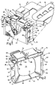
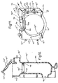
- Figure 1 illustrates a perspective view of an engine air induction system and engine radiator coolant system associated with one embodiment of a fan shroud and air intake arrangement according to the present invention;
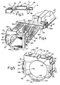
- Figure 2 is an enlarged perspective view of the fan shroud and air intake arrangement in the engine air induction system and radiator cooling system shown in Figure 1;
- Figure 3 is an enlarged fragmentary sectional view taken along the line 3-3 of Figure 2, looking in the direction of the arrows;
- Figure 4 is a perspective view of another embodiment of the invention shown in a schematic relationship to the air induction system and radiator cooling system of an internal combustion engine;
- Figure 5 is an enlarged perspective view of the fan shroud and air intake arrangement in the system of Figure 4;
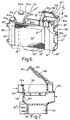
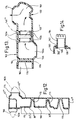
- Figure 6 is a perspective view of a fan shroud and an air intake arrangement including an air duct and an air filter box embodiment of the present invention;
- Figure 7 is an enlarged sectional view taken along the line 7-7 of Figure 6, looking in the direction of the arrows:
- Figure 8 is an enlarged sectional view taken along the line 8-8 of Figure 6, looking in the direction of the arrows;
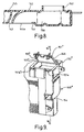
- Figure 9 is a fragmentary perspective view of another embodiment of an air duct and air filter according to the invention;
- Figure 10 is a sectional view taken along the line 10-10 of Figure 9, looking in the direction of the arrows;
- Figure 11 is a perspective view of an air duct and resonator embodiment of the present invention;
- Figure 12 is a sectional view taken along the line 12-12 of Figure 11 looking in the direction of the arrows;
- Figure 13 is a sectional view taken along the line 13-13 of Figure 11 looking in the direction of the arrows; and
- Figure 14 is a fragmentary sectional view of a modified air intake configuration for use in the embodiment of Figures 11-13.
-
- Referring now to the drawings in greater detail, Figure 1 illustrates an
internal combustion engine 10; an associatedair induction system 12 and an associatedradiator coolant system 14. - The
air induction system 12 is shown representatively and somewhat schematically. Aconduit 15 therein is connected at one end to anair cleaner 16. The opposite end ofconduit 15 is connected to anair intake manifold 18 on theengine 10. Anair intake conduit 19 connects to theair filter 16.Conduit 19 may have anoise attentuation device 20. - The
radiator coolant system 14 includes aradiator 22 shown in outline having theusual hoses radiator coolant fittings radiator 22 and the cooling passages of theengine 10. - In accordance with the present invention, the
air induction system 12 and theradiator coolant system 14 are associated with a combination fan shroud andair intake unit 30. The fan shroud andair intake unit 30 is downstream and adjacent thevehicle radiator 22 and upstream of theair induction system 12 including theair intake manifold 18. In the illustrated embodiment, asingle cooling fan 32 is mounted on theunit 30 bysuitable brackets 34. If desired theunit 30 can be a dual cooling fan arrangement as disclosed in United States Patent No. 5,649,587 commonly assigned and incorporated herein by reference. - Figure 2 shows the details of the
unit 30 with the fan removed to better show the parts of ahollow body 36 in the unit that combines fluid compartments; a fan shroud and an air induction conduit in a single unitary configuration. More particularly, thehollow body 36 has a predetermined depth between afront face 38 and arear face 40 thereof. Thefront face 38 is configured to face the front of the vehicle and is located closely adjacent the aft surfaces of theradiator 22 as best seen in Figure 1. - As will be explained more specifically herein, the
hollow body 36 has a configuration suited for formation by blow molding including techniques of the type set-forth in United States Patent No. 5,037,289 wherein hollow double walled configurations can be obtained by use of molds including male and female mold parts with pinch off points therein that will form tack off regions in the hollow body to separate various regions therein in a manner to form separate compartments of the type discussed more particularly in United States Patent No. 5,649,587. Alternatively, the hollow portions of thehollow body 36 can be formed by use of gas-assisted injection molding techniques. - In the illustrated arrangement, the
hollow body 36 is shaped between thefront face 38 and therear face 40; atop wall 42; a spaced-apart bottom wall 44; oppositely disposedside walls fan shroud wall 50 defining a primary air opening 52 through thebody 36 of a size to accommodate air flow through the radiator for cooling anti-freeze or other coolant fluids directed there through. Additionally, thebody 36 has an engineair intake conduit 54 extending rearwardly through thebody 36 from thefront face 38 to therear face 40. The engineair intake conduit 54 has anintake end 56 defining an intake opening 56a disposed adjacent thefront face 38 in communication with atmosphere. The engineair intake conduit 54 further includes anoutlet end 58 spaced apart from theintake end 56. Theoutlet end 58 includes abellows 60 thereon configured for connection to theinlet hose 19 in theair induction system 12 for theengine 10. - Flanges or
tabs 62 are formed on an edge of eachside wall flanges 62 include spacedmounting holes 64 adapted to accommodatefasteners 66 to mount thebody 36 on theradiator 12 of the vehicle involved, as shown in Figure 1. - A pair of
filler necks top wall 42 for communicating withrespective fluid chambers 72 and 74 formed within thehollow body 36, adjacent and around thecylindrical wall 50, as will be explained. A pair ofremovable caps filler neck 68 and thefiller neck 70. - As best shown in Figure 3, vertically oriented
recess 80 is formed in thetop surface 42 to provideside walls air intake duct 54. Vertically orientedrecess 86 formed in thetop surface 42 providesside walls fluid chamber 74 and one side of theair intake duct 54. A pair ofrecesses 91, 92 are provided between thebottom wall 44 and thecylindrical wall 50 to provide aseparation wall 94 between thefluid chambers 72, 74. - Thus, the chamber 72 is enclosed by the front and rear faces 38 and 40, the
top wall 42, theside wall 48, thebottom wall 44, thewalls 82 of therecess 80 and thewall 94. Thechamber 74 is enclosed byrear faces top wall 42, theside wall 46, thebottom wall 44, thewall 88 of therecess 86 and thewall 94. - As represented in phantom in Figure 3, a blow molding apparatus of the type set-forth above will have "tacks offs" T1 and T2 at the various recess points to separate the
chambers 72 and 74 and theair intake duct 54 in the molding process. - Referring to the embodiment of Figure 4, a combination fan shroud and
air intake unit 100 is shown. The fan shroud andair intake unit 100 is downstream and adjacent a vehicle radiator 22' and upstream of an air induction system 12' including an air intake manifold 20'. In this embodiment, the induction system is coupled to the fan shroud andair intake unit 100 by anadapter fitting 102 having threeintake branches common manifold 102d that includes an outlet fitting 102e connecting to an air intake hose 18'. In the illustrated embodiment, a single cooling fan 32' is mounted on theunit 100 by suitable brackets 34'. If desired, theunit 100 of this embodiment can also be a dual cooling fan arrangement as disclosed in United States Patent No. 5,649,587. Theunit 100 includes a hollow body 36' of a predetermined depth and having a front face 38' adapted to face the front of the vehicle and being adjacent to the radiator 22'. - As best shown in Figure 5, where the fan is omitted for purposes of better showing the component parts of the hollow body 36', pairs of recessed
surfaces side wall 108 and acylindrical wall 110 to form a first air intake conduit 112. Likewise, pairs of recessedsurfaces side wall 118 andcylindrical wall 110 form a secondair intake conduit 120 on the hollow body 36'. Pairs of recessedsurfaces bottom wall 126 to form athird air conduit 128. Theair conduits fan shroud surface 110. Theconduits intake branches air intake conduits intake branches - In the embodiment of Figure 5, the fan shroud and
air intake unit 100 further includes aunitary coolant chamber 130 and a unitarywasher fluid chamber 132 separated by a common wall formed by a recessedsurface 134 formed in thetop surface 136 of the fan shroud andair intake unit 100.Filler necks top surface 136 for directing fluid into thecoolant tank 130 and thewasher fluid chamber 132, respectively.Caps filler necks - Referring to the embodiment of the invention shown in Figure 6, a fan shroud and
air intake unit 140 is illustrated having a hollowunitary body 36". - More particularly, the
hollow body 36" has a predetermined depth between afront face 38" and arear face 40" thereof. Thefront face 38" is configured to face the front of the vehicle and is located closely adjacent the aft surfaces of theradiator 22" as best seen in Figure 7. - In the illustrated arrangement the
hollow body 36" is shaped between thefront face 38" and therear face 40"; atop wall 42"; a spaced-apartbottom wall 44"; oppositely disposedside walls 46", 48" and at least one innerfan shroud wall 50" defining aprimary air opening 52" through thebody 36" of a size to accommodate air flow through the radiator for cooling anti-freeze or other coolant fluids directed there through. Additionally, thebody 36" has an engineair intake conduit 142 formed therein at recessedsurfaces 143, 145 intop wall 42" formed between thefront face 38" and therear face 40". Theair intake conduit 142 extends rearwardly and laterally from anintake end 144 defining anintake opening 144a disposed adjacent thefront face 38" in communication with atmosphere. Theair intake conduit 142 includes a hinged blow moldeddoor panel 146 that provides access into theconduit 142 where acavity 148 is provided withsupport rib 149 for locating anair filter element 150 within thecavity 148. Thehollow housing 36" includes anair outlet 152 that communicates with thecavity 148 and is adapted to be connected to air hoses of the types shown in the embodiments of Figures 1 and 4 for supplying filtered air flow to the air induction system of a combustion engine. If desired, theunit 150 can include two unitizedfluid chambers suitable filler necks closures 153b and 155b can be provided. - Figures 9 and 10 show a fragmentary view of alternative air intake
air conduit unit 140" having a unitary air filter cavity. In this embodiment anair intake 154 is located at a lower side segment of theunit 140". This is a preferred location when space and connection arrangements do not make it possible to have a top air intake as in the embodiment of Figures 6-8. In the arrangement of Figure 9, theair intake 154 directs air into a vertically disposed, side locatedcavity 156 within theunit 140". Thecavity 156 is closed at its top by a hinged blow moldeddoor panel 146" that provides access into thecavity 156.Supports ribs 158 are provided within thecavity 156 for locating anair filter element 150" within thecavity 156 at a point below anair outlet 152" that communicates with thecavity 156 and is adapted to be connected to air hoses of the types shown in the embodiments of Figures 1 and 4 for supplying filtered air flow to the air induction system of a combustion engine. - In both the embodiment Fig. 6 and Fig. 9, the
door panel annular perimeter seal latches door panels latches ribs - Another embodiment of the invention is illustrated in Figures 11-13 as including a fan shroud and
air conduit unit 160 having a unitizedresonator chamber 168. More particularly, as in the prior embodiment the fan shroud andair conduit unit 160 is illustrated as having a hollowunitary body 36"'. - More particularly, the
hollow body 36"' has a predetermined depth between afront face 38"' and arear face 40"'. Thefront face 38"' is configured to face the front of the vehicle and is located closely adjacent the aft surfaces of the radiator 22'" as best seen in Figure 12. - In the illustrated arrangement, as shown in Figures 11 and 12, the hollow body 36'" is shaped between the
front face 38"' and therear face 40"'; atop wall 42"'; a spaced-apartbottom wall 44"'; oppositely disposedside walls 46"', 48"' and at least one innerfan shroud wall 50"' defining aprimary air opening 52"' through the body 36'" of a size to accommodate air flow through the radiator 22''' for cooling anti-freeze or other coolant fluids directed there through. Additionally, the body 36'" has an engine air intake conduit orduct 162 formed therein at a recessedsurface 164 formed between thefront face 38"' therear face 40"'. Theair intake conduit 162 has anair inlet 166 defining anopening 166a. Theinlet 166 communicates with aresonator chamber 168 formed on one side of theunit 160. The height of thechamber 168 can be selected to define a quarter wave length tube by locating a recessedsurface 170 in theunit 160 at thefront face 38"' thereof to seal off the lower end of theresonator chamber 168. In the illustrated embodiment, therear face 40"' includes a pair of spaced cone-shapedtack offs chamber 168 to prevent collapse of the wall of the resonator. The tack-offs depressed region 175 for stiffening the reservoir wall. Anoutlet 174 fromconduit 162 is configured to be connected to the inlet air hose of an air induction system of the type shown in prior embodiments. - In this embodiment, a tack-off or
recess 164 is provided to definewalls 176, 178 (Figure 13) for separating theair conduit passage 166a from afluid chamber 182 that can serve either as a windshield wiper fluid container or as a coolant recovery reservoir. In the embodiment of Figures 11-13, the inlet and outlets of theconduit 162 are formed following blow molding by removing the ends of blown hollow portions of the hollow body as shown in outline at 162b and 162c in Figure 12. Theportions integrally mold tabs 62"' configured to be secured to an associated radiator. - Furthermore, as shown in Figure 13, an air filter 150''' is inserted in molded
ribs 162a formed at four spaced points inair conduit 162. It is accessed for replacement or cleaning through a door panel 146''' connected and sealed like those in the previous embodiments. - In another embodiment of the invention, shown in Figure 14, the blow mold for shaping the hollow body does not include the
hollow portions hollow body 180 is formed; anopening 182 is formed in its wall and a moldedtube insert 184 has aflanged end 186 thereon connected to an annular connecting groove 188 (that can be formed during blow molding of the hollow body 180) for fixing thetube insert 184 to thehollow body 180. Thetube insert 184 directs inlet air into a resonator chamber 168' corresponding to that in Figure 12. The outlet from the chamber 168' can be formed by a tube insert like theinsert 184 connected in a similar manner. The connection of the tube insert to the hollow body is illustrative in nature with it being understood that a wide range of connections will serve the same purpose including laser or sonic weld connections; bayonet connections; expandable barb type connections; thread connections and the like. - It should be apparent that the invention provides a compact fan shroud receptacle and engine inlet air structure which eliminates the need for space and fastening means for a wide range of separate components in the already crowded engine compartment of today's automobile. It provides substantial cost savings by virtue of having eliminated the need to manufacture and assemble various parts associated with underhood systems, while utilizing heretofore unused surface areas of the fan shroud.
- Additionally, the invention may provide a standard or uniform structure which is unaffected by many new vehicular designs. Specifically, the shape of the fluid chambers; air intake conduits; air filter chambers; resonator chambers and the like need not be redesigned each time the fender wells and other interior parts are changed on at least some new vehicle models. Also, the integrally molded windshield washer fluid or headlamp washer fluid compartments may have a larger capacity than the previously employed separate containers.
- Furthermore, the resultant structure is extremely rigid, both radially and axially, and damped by fluid in the receptacles, reducing vibration or excitation of the fan shroud caused by the rotating fan surrounded thereby, hence diminishing a possible source of bothersome noise.
- While but one embodiment of the invention has been shown and described, other modifications thereof are possible within the scope of the following claims.
Claims (25)
- A combination fan shroud and air intake air for use adjacent a vehicle radiator and an air intake manifold assembly, and around one or more cooling fans, the unit having a body (36) of a predetermined depth and having a front face (38) adapted to face the front of the vehicle and being adjacent to the radiator, a rear face (40) spaced apart from said front face, a top wall (42) and a spaced-apart bottom wall (44), oppositely disposed side walls (46, 48), and at least one inner wall (50) defining an opening through said body of a size to accommodate air flow through the radiator, characterised in that said body (36) defines at least one air intake conduit (54) extending rearwardly through said body from said front face, said air intake conduit having an intake end (56) defining an intake opening disposed adjacent said front face and an outlet end (58) spaced apart from said intake end and adapted to communicate with the intake manifold assembly.
- The combination as claimed in claim 1 further including an air induction noise reduction device (168) downstream of said intake end, said noise reduction device being integral with said body and being in communication with said air intake conduit.
- The combination as claimed in claim 2 wherein said noise reduction device is a resonator (168).
- The combination as claimed in claim 3 wherein said resonator is a quarter wave tube.
- The combination as claimed in any one of the preceding claims characterised by further including an air filter housing (156) formed integrally with said body and disposed between said intake and outlet ends whereby said air filter housing is adapted to receive an air filter for filtering air passing therethrough.
- The combination as claimed in any one of the preceding claims, characterised in that said air intake conduit (54) is positioned on said top wall.
- The combination of claim 6 characterised in that there is one air intake conduit.
- The combination as claimed in any one of claims 1 to 6 characterised in that more than one air intake conduits are spaced apart about the periphery of said body.
- The combination of claim 8 wherein there are three air intake conduits (112, 120, 128).
- The combination as claimed in any one of the preceding claims, characterised in that said body is formed from blow moulded plastic.
- The combination as claimed in any one claims 1 to 10, characterised in that said body (36) is formed from gas-assist injection moulded plastic.
- A fan shroud, receptacle and engine air inlet arrangement for use adjacent a vehicle radiator and around one or two engine cooling fans, the arrangement comprising a rectangularly shaped hollow body (36') of a predetermined depth and having a front face (38') a rear face, a top wall, a bottom wall, oppositely disposed side walls, at least one opening formed through the body and having a cylindrical wall (50) therearound defining a fan shroud characterised by a recess (80) formed in at least one of the front and rear faces to form a wall for dividing the hollow body into two separate hollow openings; one of said openings configured as a fluid chamber the other of said openings configured as an engine air intake conduit having an inlet end and an outlet end.
- The fan shroud, receptacle and engine air inlet arrangement as claimed in claim 12, characterised in that the wall for dividing the hollow body into two separate hollow openings is formed with respect to said cylindrical wall.
- The fan shroud, receptacle and engine air inlet arrangement as claimed in claim 12 or 13, characterised by including two openings having cylindrical walls therearound forming spaced apart fan shrouds configured to direct air flow from a pair of fans.
- The combination as claimed in any one of claims 12 to 14, characterised by further including an air induction noise reduction device (168) downstream of said intake end, said noise reduction device being integral with said body and being in communication with said air intake conduit.
- The combination as claimed in claim 15 wherein said noise reduction device is a resonator.
- The combination as claimed in claim 16 wherein said resonator is a quarter wave tube.
- The combination as claimed in any one of claims 12 to 17, characterised by further including an air filter housing formed integrally with said body and disposed between said intake and outlet ends whereby said air filter housing is adapted to receive an air filter (150"') for filtering air passing therethrough.
- The combination as claimed in any one of claims 12 to 18, characterised in that said engine air intake conduit is positioned on said top wall.
- The combination as claimed in claim 19 wherein there is one engine air intake conduit.
- The combination as claimed in any one of claims 12 to 18, characterised in that more than one engine air intake conduits are spaced apart about the periphery of said body.
- The combination of claim 21 wherein there are three air intake conduits.
- The combination as claimed in any one of claims 12 to 22, characterised in that said body is formed from blow moulded plastic.
- The combination as claimed in any one of claims 12 to 22, characterised in that said body is formed from gas-assist injection moulded plastic.
- The combination as claimed in any one of claims 1 to 11, characterised by further comprising at least one integrally formal fluid chamber (72).
Applications Claiming Priority (2)
| Application Number | Priority Date | Filing Date | Title |
|---|---|---|---|
| US17745898A | 1998-10-22 | 1998-10-22 | |
| US177458 | 1998-10-22 |
Publications (4)
| Publication Number | Publication Date |
|---|---|
| EP0995895A2 true EP0995895A2 (en) | 2000-04-26 |
| EP0995895A3 EP0995895A3 (en) | 2000-08-09 |
| EP0995895B1 EP0995895B1 (en) | 2004-03-24 |
| EP0995895B8 EP0995895B8 (en) | 2004-07-14 |
Family
ID=22648677
Family Applications (1)
| Application Number | Title | Priority Date | Filing Date |
|---|---|---|---|
| EP99308188A Expired - Lifetime EP0995895B8 (en) | 1998-10-22 | 1999-10-18 | Fan shroud and air intake arrangement |
Country Status (8)
| Country | Link |
|---|---|
| EP (1) | EP0995895B8 (en) |
| JP (1) | JP2003524095A (en) |
| AT (1) | ATE262645T1 (en) |
| CA (1) | CA2346812A1 (en) |
| DE (1) | DE69915764T2 (en) |
| ES (1) | ES2217699T3 (en) |
| MX (1) | MXPA01003866A (en) |
| WO (1) | WO2000023696A1 (en) |
Cited By (15)
| Publication number | Priority date | Publication date | Assignee | Title |
|---|---|---|---|---|
| EP1128071A3 (en) * | 2000-02-25 | 2002-06-12 | Inoac Corporation | Resonator-integrated fan shroud |
| EP1369576A2 (en) * | 2002-06-03 | 2003-12-10 | Siemens VDO Automotive Inc. | Integrated engine compartment component and air intake system |
| EP1637726A1 (en) * | 2004-09-17 | 2006-03-22 | Bayerische Motoren Werke Aktiengesellschaft | Arrangement of an air filter housing for an internal combustion engine in the motor compartment of a motor vehicle |
| FR2890701A1 (en) * | 2005-09-12 | 2007-03-16 | Renault Sas | ASSEMBLY COMPRISING A NOISE MITIGATION DEVICE AND AN AIR CONDUIT OF A MOTOR BLOCK CONNECTED BY CLOSURE-LOCKING |
| EP1995103A1 (en) * | 2007-05-23 | 2008-11-26 | Denso Corporation | Cooling module |
| EP2048334A3 (en) * | 2007-10-03 | 2009-12-02 | Toyota Jidosha Kabusiki Kaisha | Vehicular cooling apparatus |
| FR2933043A1 (en) * | 2008-06-27 | 2010-01-01 | Renault Sas | Internal combustion engine's air intake pipe fixing arrangement for motor vehicle, has housing opened on upper surface, front surface and on rear surface of shroud, and convergent element is positioned and maintained in position in housing |
| FR2933045A1 (en) * | 2008-06-27 | 2010-01-01 | Renault Sas | Air intake pipe fixation system for fan fairing in motor vehicle, has groove extended in bottom of housing of fairing, where upper face of fairing has bonnet movable between open position and closed position in which bonnet closes opening |
| CN101096936B (en) * | 2006-06-08 | 2010-08-11 | 株式会社电装 | Inlet device for gas engine and exterior air inlet module for vehicle |
| EP1650426A3 (en) * | 2004-10-25 | 2012-02-22 | Deere & Company | Utility Vehicle |
| CN104002871A (en) * | 2014-06-17 | 2014-08-27 | 安徽江淮汽车股份有限公司 | Light bus and front end modularized assembly thereof |
| CN106042902A (en) * | 2015-04-01 | 2016-10-26 | 通用汽车环球科技运作有限责任公司 | Multi-stage fresh air inlet system |
| CN106988855A (en) * | 2017-05-11 | 2017-07-28 | 廖兴池 | Special engine heat dissipating device on a kind of unmanned plane |
| US10012130B2 (en) * | 2015-07-23 | 2018-07-03 | Honda Motor Co., Ltd. | Cooling system |
| DE102008058431B4 (en) | 2007-11-26 | 2019-10-02 | Denso Corporation | Air cleaner unit for vehicle and fan cover with this |
Families Citing this family (13)
| Publication number | Priority date | Publication date | Assignee | Title |
|---|---|---|---|---|
| US7237635B2 (en) | 2004-07-12 | 2007-07-03 | Honda Motor Co., Ltd. | Automobile over-bulkhead air intake system |
| US7234555B2 (en) | 2004-07-12 | 2007-06-26 | Honda Motor Co., Ltd. | Secondary path automobile air intake system |
| US8201651B2 (en) | 2004-07-12 | 2012-06-19 | Honda Motor Co., Ltd. | Automobile over-bulkhead air intake system |
| JP2006290046A (en) * | 2005-04-06 | 2006-10-26 | Calsonic Kansei Corp | Radiator core support structure |
| JP4650228B2 (en) * | 2005-11-21 | 2011-03-16 | 日産自動車株式会社 | Intake device for internal combustion engine |
| JP4626815B2 (en) * | 2005-12-28 | 2011-02-09 | スズキ株式会社 | Intake device for vehicle engine |
| JP5024894B2 (en) * | 2007-10-03 | 2012-09-12 | トヨタ自動車株式会社 | Vehicle cooling system |
| DE202008014211U1 (en) | 2008-10-24 | 2010-03-11 | Mann+Hummel Gmbh | Air filter for the air supplied to an internal combustion engine in a motor vehicle |
| US8807113B2 (en) * | 2009-05-04 | 2014-08-19 | Ford Global Technologies, Llc | Device and method for integrating an air cleaner into a radiator fan shroud |
| US8540043B2 (en) | 2010-08-30 | 2013-09-24 | Honda Motor Co., Ltd. | Over bulkhead air intake for reduced snow ingestion |
| US8439143B2 (en) | 2011-02-21 | 2013-05-14 | Honda Motor Co., Ltd. | Over bulkhead air intake system |
| JP5917383B2 (en) * | 2012-12-11 | 2016-05-11 | 日立建機株式会社 | Construction machinery |
| JP6699186B2 (en) * | 2016-01-18 | 2020-05-27 | トヨタ自動車株式会社 | Radiator support |
Citations (5)
| Publication number | Priority date | Publication date | Assignee | Title |
|---|---|---|---|---|
| US2197503A (en) * | 1938-04-30 | 1940-04-16 | Oliver Farm Equipment Co | Air intake for air cleaners |
| DE8620190U1 (en) * | 1986-07-28 | 1986-09-18 | Wengler, Walter, 8600 Bamberg | Intake device for internal combustion engines |
| JPH06257524A (en) * | 1993-03-05 | 1994-09-13 | Nissan Motor Co Ltd | Intake air manifold supporting construction of transversely-mounted engine |
| US5427502A (en) * | 1994-03-28 | 1995-06-27 | Deere & Company | Fan shroud aspirator |
| US5649587A (en) * | 1996-02-23 | 1997-07-22 | Mccord Winn Textron, Inc. | Fan shroud and receptacle arrangement |
Family Cites Families (4)
| Publication number | Priority date | Publication date | Assignee | Title |
|---|---|---|---|---|
| DE3112630A1 (en) * | 1981-03-30 | 1982-10-07 | Volkswagenwerk Ag, 3180 Wolfsburg | Cooling device for a liquid-cooled internal combustion engine arranged in an engine compartment of a motor vehicle |
| DE4018347A1 (en) * | 1990-06-08 | 1991-12-12 | Audi Ag | ARRANGEMENT FOR COOLING THE BATTERY OF A MOTOR VEHICLE |
| US5333576A (en) * | 1993-03-31 | 1994-08-02 | Ford Motor Company | Noise attenuation device for air induction system for internal combustion engine |
| US5899196A (en) * | 1997-12-19 | 1999-05-04 | Jeffrey S. Melcher | Method and apparatus for supplying warm air to an air intake of an engine |
-
1999
- 1999-09-23 WO PCT/US1999/022112 patent/WO2000023696A1/en active Application Filing
- 1999-09-23 MX MXPA01003866A patent/MXPA01003866A/en not_active Application Discontinuation
- 1999-09-23 CA CA002346812A patent/CA2346812A1/en not_active Abandoned
- 1999-09-23 JP JP2000577395A patent/JP2003524095A/en not_active Withdrawn
- 1999-10-18 ES ES99308188T patent/ES2217699T3/en not_active Expired - Lifetime
- 1999-10-18 EP EP99308188A patent/EP0995895B8/en not_active Expired - Lifetime
- 1999-10-18 DE DE69915764T patent/DE69915764T2/en not_active Expired - Fee Related
- 1999-10-18 AT AT99308188T patent/ATE262645T1/en not_active IP Right Cessation
Patent Citations (5)
| Publication number | Priority date | Publication date | Assignee | Title |
|---|---|---|---|---|
| US2197503A (en) * | 1938-04-30 | 1940-04-16 | Oliver Farm Equipment Co | Air intake for air cleaners |
| DE8620190U1 (en) * | 1986-07-28 | 1986-09-18 | Wengler, Walter, 8600 Bamberg | Intake device for internal combustion engines |
| JPH06257524A (en) * | 1993-03-05 | 1994-09-13 | Nissan Motor Co Ltd | Intake air manifold supporting construction of transversely-mounted engine |
| US5427502A (en) * | 1994-03-28 | 1995-06-27 | Deere & Company | Fan shroud aspirator |
| US5649587A (en) * | 1996-02-23 | 1997-07-22 | Mccord Winn Textron, Inc. | Fan shroud and receptacle arrangement |
Non-Patent Citations (1)
| Title |
|---|
| PATENT ABSTRACTS OF JAPAN vol. 018, no. 660 (M-1722), 14 December 1994 (1994-12-14) & JP 06 257524 A (NISSAN MOTOR CO LTD), 13 September 1994 (1994-09-13) * |
Cited By (19)
| Publication number | Priority date | Publication date | Assignee | Title |
|---|---|---|---|---|
| EP1128071A3 (en) * | 2000-02-25 | 2002-06-12 | Inoac Corporation | Resonator-integrated fan shroud |
| US6499956B2 (en) | 2000-02-25 | 2002-12-31 | Inoac Corporation | Resonator-integrated fan shroud and resonator-integrated fan shroud with air intake duct |
| EP1369576A2 (en) * | 2002-06-03 | 2003-12-10 | Siemens VDO Automotive Inc. | Integrated engine compartment component and air intake system |
| EP1369576A3 (en) * | 2002-06-03 | 2006-06-28 | Siemens VDO Automotive Inc. | Integrated engine compartment component and air intake system |
| EP1637726A1 (en) * | 2004-09-17 | 2006-03-22 | Bayerische Motoren Werke Aktiengesellschaft | Arrangement of an air filter housing for an internal combustion engine in the motor compartment of a motor vehicle |
| EP1650426A3 (en) * | 2004-10-25 | 2012-02-22 | Deere & Company | Utility Vehicle |
| FR2890701A1 (en) * | 2005-09-12 | 2007-03-16 | Renault Sas | ASSEMBLY COMPRISING A NOISE MITIGATION DEVICE AND AN AIR CONDUIT OF A MOTOR BLOCK CONNECTED BY CLOSURE-LOCKING |
| WO2007031680A1 (en) * | 2005-09-12 | 2007-03-22 | Renault S.A.S | Assembly comprising a noise attenuating device and an engine unit air duct sealingly connected by click-stop mechanism |
| CN101096936B (en) * | 2006-06-08 | 2010-08-11 | 株式会社电装 | Inlet device for gas engine and exterior air inlet module for vehicle |
| EP1995103A1 (en) * | 2007-05-23 | 2008-11-26 | Denso Corporation | Cooling module |
| EP2048334A3 (en) * | 2007-10-03 | 2009-12-02 | Toyota Jidosha Kabusiki Kaisha | Vehicular cooling apparatus |
| DE102008058431B4 (en) | 2007-11-26 | 2019-10-02 | Denso Corporation | Air cleaner unit for vehicle and fan cover with this |
| FR2933043A1 (en) * | 2008-06-27 | 2010-01-01 | Renault Sas | Internal combustion engine's air intake pipe fixing arrangement for motor vehicle, has housing opened on upper surface, front surface and on rear surface of shroud, and convergent element is positioned and maintained in position in housing |
| FR2933045A1 (en) * | 2008-06-27 | 2010-01-01 | Renault Sas | Air intake pipe fixation system for fan fairing in motor vehicle, has groove extended in bottom of housing of fairing, where upper face of fairing has bonnet movable between open position and closed position in which bonnet closes opening |
| CN104002871A (en) * | 2014-06-17 | 2014-08-27 | 安徽江淮汽车股份有限公司 | Light bus and front end modularized assembly thereof |
| CN106042902A (en) * | 2015-04-01 | 2016-10-26 | 通用汽车环球科技运作有限责任公司 | Multi-stage fresh air inlet system |
| CN106042902B (en) * | 2015-04-01 | 2018-08-10 | 通用汽车环球科技运作有限责任公司 | Multistage fresh air inlet system |
| US10012130B2 (en) * | 2015-07-23 | 2018-07-03 | Honda Motor Co., Ltd. | Cooling system |
| CN106988855A (en) * | 2017-05-11 | 2017-07-28 | 廖兴池 | Special engine heat dissipating device on a kind of unmanned plane |
Also Published As
| Publication number | Publication date |
|---|---|
| EP0995895A3 (en) | 2000-08-09 |
| ATE262645T1 (en) | 2004-04-15 |
| MXPA01003866A (en) | 2002-05-06 |
| DE69915764D1 (en) | 2004-04-29 |
| WO2000023696A1 (en) | 2000-04-27 |
| JP2003524095A (en) | 2003-08-12 |
| DE69915764T2 (en) | 2005-03-17 |
| EP0995895B8 (en) | 2004-07-14 |
| CA2346812A1 (en) | 2000-04-27 |
| EP0995895B1 (en) | 2004-03-24 |
| ES2217699T3 (en) | 2004-11-01 |
Similar Documents
| Publication | Publication Date | Title |
|---|---|---|
| EP0995895B1 (en) | Fan shroud and air intake arrangement | |
| CA2247153C (en) | Fan shroud and receptacle arrangement | |
| US6189492B1 (en) | Automotive fan shroud and method of making | |
| US6499956B2 (en) | Resonator-integrated fan shroud and resonator-integrated fan shroud with air intake duct | |
| US6067953A (en) | Integrated intake manifold and air cleaner system | |
| US7143736B2 (en) | Filter box with resonator and reservoir | |
| US6062304A (en) | Heat exchanger for a water-cooled internal combustion engine | |
| US5913295A (en) | Combination air cleaner fluid reservoir | |
| EP1369576B1 (en) | Integrated engine compartment component and air intake system | |
| CN1196594A (en) | Storage box for electronic control units | |
| US20040182348A1 (en) | Air intake assembly for vehicle engine and method of manufacturing same | |
| JP2003161216A (en) | Intake unit | |
| KR100235745B1 (en) | Air filter for an automobile | |
| JPH11336625A (en) | Intake device for internal combustion engine | |
| US6776444B2 (en) | Dashboard designed to be mounted in an interior of a vehicle, as well as to a vehicle body equipped with such a dashboard | |
| JPS61150815A (en) | Air conditioner for automobile | |
| US6343983B1 (en) | Ventilation box for arrangement in a motor vehicle | |
| JP3952767B2 (en) | Intake module | |
| JP2005035465A (en) | Ceiling cooler unit for vehicle | |
| CN215064022U (en) | Air conditioner cleaning system for vehicle | |
| JPS6136738Y2 (en) | ||
| JPH10138751A (en) | Air-condition duct | |
| EP1409327A2 (en) | Vehicle fascia support with integral fluid reservoir | |
| JP2000186638A (en) | Intake device for internal combustion engine | |
| JPH05105037A (en) | Outside air inlet structure of automobile |
Legal Events
| Date | Code | Title | Description |
|---|---|---|---|
| PUAI | Public reference made under article 153(3) epc to a published international application that has entered the european phase |
Free format text: ORIGINAL CODE: 0009012 |
|
| AK | Designated contracting states |
Kind code of ref document: A2 Designated state(s): AT BE CH CY DE DK ES FI FR GB GR IE IT LI LU MC NL PT SE |
|
| AX | Request for extension of the european patent |
Free format text: AL;LT;LV;MK;RO;SI |
|
| RIN1 | Information on inventor provided before grant (corrected) |
Inventor name: PLANT, WILLIAM DAVID |
|
| PUAL | Search report despatched |
Free format text: ORIGINAL CODE: 0009013 |
|
| AK | Designated contracting states |
Kind code of ref document: A3 Designated state(s): AT BE CH CY DE DK ES FI FR GB GR IE IT LI LU MC NL PT SE |
|
| AX | Request for extension of the european patent |
Free format text: AL;LT;LV;MK;RO;SI |
|
| 17P | Request for examination filed |
Effective date: 20010202 |
|
| AKX | Designation fees paid |
Free format text: AT BE CH CY DE DK ES FI FR GB GR IE IT LI LU MC NL PT SE |
|
| 17Q | First examination report despatched |
Effective date: 20030303 |
|
| GRAP | Despatch of communication of intention to grant a patent |
Free format text: ORIGINAL CODE: EPIDOSNIGR1 |
|
| GRAS | Grant fee paid |
Free format text: ORIGINAL CODE: EPIDOSNIGR3 |
|
| GRAA | (expected) grant |
Free format text: ORIGINAL CODE: 0009210 |
|
| AK | Designated contracting states |
Kind code of ref document: B1 Designated state(s): AT BE CH CY DE DK ES FI FR GB GR IE IT LI LU MC NL PT SE |
|
| PG25 | Lapsed in a contracting state [announced via postgrant information from national office to epo] |
Ref country code: NL Free format text: LAPSE BECAUSE OF FAILURE TO SUBMIT A TRANSLATION OF THE DESCRIPTION OR TO PAY THE FEE WITHIN THE PRESCRIBED TIME-LIMIT Effective date: 20040324 Ref country code: LI Free format text: LAPSE BECAUSE OF FAILURE TO SUBMIT A TRANSLATION OF THE DESCRIPTION OR TO PAY THE FEE WITHIN THE PRESCRIBED TIME-LIMIT Effective date: 20040324 Ref country code: FI Free format text: LAPSE BECAUSE OF FAILURE TO SUBMIT A TRANSLATION OF THE DESCRIPTION OR TO PAY THE FEE WITHIN THE PRESCRIBED TIME-LIMIT Effective date: 20040324 Ref country code: CY Free format text: LAPSE BECAUSE OF FAILURE TO SUBMIT A TRANSLATION OF THE DESCRIPTION OR TO PAY THE FEE WITHIN THE PRESCRIBED TIME-LIMIT Effective date: 20040324 Ref country code: CH Free format text: LAPSE BECAUSE OF FAILURE TO SUBMIT A TRANSLATION OF THE DESCRIPTION OR TO PAY THE FEE WITHIN THE PRESCRIBED TIME-LIMIT Effective date: 20040324 Ref country code: BE Free format text: LAPSE BECAUSE OF FAILURE TO SUBMIT A TRANSLATION OF THE DESCRIPTION OR TO PAY THE FEE WITHIN THE PRESCRIBED TIME-LIMIT Effective date: 20040324 Ref country code: AT Free format text: LAPSE BECAUSE OF FAILURE TO SUBMIT A TRANSLATION OF THE DESCRIPTION OR TO PAY THE FEE WITHIN THE PRESCRIBED TIME-LIMIT Effective date: 20040324 |
|
| REG | Reference to a national code |
Ref country code: GB Ref legal event code: FG4D |
|
| REG | Reference to a national code |
Ref country code: CH Ref legal event code: EP |
|
| REG | Reference to a national code |
Ref country code: IE Ref legal event code: FG4D |
|
| REF | Corresponds to: |
Ref document number: 69915764 Country of ref document: DE Date of ref document: 20040429 Kind code of ref document: P |
|
| PG25 | Lapsed in a contracting state [announced via postgrant information from national office to epo] |
Ref country code: SE Free format text: LAPSE BECAUSE OF FAILURE TO SUBMIT A TRANSLATION OF THE DESCRIPTION OR TO PAY THE FEE WITHIN THE PRESCRIBED TIME-LIMIT Effective date: 20040624 Ref country code: GR Free format text: LAPSE BECAUSE OF FAILURE TO SUBMIT A TRANSLATION OF THE DESCRIPTION OR TO PAY THE FEE WITHIN THE PRESCRIBED TIME-LIMIT Effective date: 20040624 Ref country code: DK Free format text: LAPSE BECAUSE OF FAILURE TO SUBMIT A TRANSLATION OF THE DESCRIPTION OR TO PAY THE FEE WITHIN THE PRESCRIBED TIME-LIMIT Effective date: 20040624 |
|
| NLV1 | Nl: lapsed or annulled due to failure to fulfill the requirements of art. 29p and 29m of the patents act | ||
| REG | Reference to a national code |
Ref country code: CH Ref legal event code: PL |
|
| PG25 | Lapsed in a contracting state [announced via postgrant information from national office to epo] |
Ref country code: LU Free format text: LAPSE BECAUSE OF NON-PAYMENT OF DUE FEES Effective date: 20041018 Ref country code: IE Free format text: LAPSE BECAUSE OF NON-PAYMENT OF DUE FEES Effective date: 20041018 |
|
| PGFP | Annual fee paid to national office [announced via postgrant information from national office to epo] |
Ref country code: ES Payment date: 20041026 Year of fee payment: 6 |
|
| PG25 | Lapsed in a contracting state [announced via postgrant information from national office to epo] |
Ref country code: MC Free format text: LAPSE BECAUSE OF NON-PAYMENT OF DUE FEES Effective date: 20041031 |
|
| REG | Reference to a national code |
Ref country code: ES Ref legal event code: FG2A Ref document number: 2217699 Country of ref document: ES Kind code of ref document: T3 |
|
| ET | Fr: translation filed | ||
| PLBE | No opposition filed within time limit |
Free format text: ORIGINAL CODE: 0009261 |
|
| STAA | Information on the status of an ep patent application or granted ep patent |
Free format text: STATUS: NO OPPOSITION FILED WITHIN TIME LIMIT |
|
| 26N | No opposition filed |
Effective date: 20041228 |
|
| PG25 | Lapsed in a contracting state [announced via postgrant information from national office to epo] |
Ref country code: IT Free format text: LAPSE BECAUSE OF NON-PAYMENT OF DUE FEES Effective date: 20051018 |
|
| PG25 | Lapsed in a contracting state [announced via postgrant information from national office to epo] |
Ref country code: ES Free format text: LAPSE BECAUSE OF NON-PAYMENT OF DUE FEES Effective date: 20051019 |
|
| REG | Reference to a national code |
Ref country code: IE Ref legal event code: MM4A |
|
| REG | Reference to a national code |
Ref country code: ES Ref legal event code: FD2A Effective date: 20051019 |
|
| PG25 | Lapsed in a contracting state [announced via postgrant information from national office to epo] |
Ref country code: PT Free format text: LAPSE BECAUSE OF NON-PAYMENT OF DUE FEES Effective date: 20040824 |
|
| PGFP | Annual fee paid to national office [announced via postgrant information from national office to epo] |
Ref country code: DE Payment date: 20071005 Year of fee payment: 9 |
|
| PGFP | Annual fee paid to national office [announced via postgrant information from national office to epo] |
Ref country code: GB Payment date: 20071023 Year of fee payment: 9 Ref country code: FR Payment date: 20071016 Year of fee payment: 9 |
|
| GBPC | Gb: european patent ceased through non-payment of renewal fee |
Effective date: 20081018 |
|
| REG | Reference to a national code |
Ref country code: FR Ref legal event code: ST Effective date: 20090630 |
|
| PG25 | Lapsed in a contracting state [announced via postgrant information from national office to epo] |
Ref country code: DE Free format text: LAPSE BECAUSE OF NON-PAYMENT OF DUE FEES Effective date: 20090501 |
|
| PG25 | Lapsed in a contracting state [announced via postgrant information from national office to epo] |
Ref country code: FR Free format text: LAPSE BECAUSE OF NON-PAYMENT OF DUE FEES Effective date: 20081031 |
|
| PG25 | Lapsed in a contracting state [announced via postgrant information from national office to epo] |
Ref country code: GB Free format text: LAPSE BECAUSE OF NON-PAYMENT OF DUE FEES Effective date: 20081018 |