EP0986348B1 - Natural tissue heart valve prosthesis - Google Patents
Natural tissue heart valve prosthesis Download PDFInfo
- Publication number
- EP0986348B1 EP0986348B1 EP99912867A EP99912867A EP0986348B1 EP 0986348 B1 EP0986348 B1 EP 0986348B1 EP 99912867 A EP99912867 A EP 99912867A EP 99912867 A EP99912867 A EP 99912867A EP 0986348 B1 EP0986348 B1 EP 0986348B1
- Authority
- EP
- European Patent Office
- Prior art keywords
- heart valve
- leaflets
- side wall
- adjacent
- wall portion
- Prior art date
- Legal status (The legal status is an assumption and is not a legal conclusion. Google has not performed a legal analysis and makes no representation as to the accuracy of the status listed.)
- Expired - Lifetime
Links
Images

Classifications
-
- A—HUMAN NECESSITIES
- A61—MEDICAL OR VETERINARY SCIENCE; HYGIENE
- A61F—FILTERS IMPLANTABLE INTO BLOOD VESSELS; PROSTHESES; DEVICES PROVIDING PATENCY TO, OR PREVENTING COLLAPSING OF, TUBULAR STRUCTURES OF THE BODY, e.g. STENTS; ORTHOPAEDIC, NURSING OR CONTRACEPTIVE DEVICES; FOMENTATION; TREATMENT OR PROTECTION OF EYES OR EARS; BANDAGES, DRESSINGS OR ABSORBENT PADS; FIRST-AID KITS
- A61F2/00—Filters implantable into blood vessels; Prostheses, i.e. artificial substitutes or replacements for parts of the body; Appliances for connecting them with the body; Devices providing patency to, or preventing collapsing of, tubular structures of the body, e.g. stents
- A61F2/02—Prostheses implantable into the body
- A61F2/24—Heart valves ; Vascular valves, e.g. venous valves; Heart implants, e.g. passive devices for improving the function of the native valve or the heart muscle; Transmyocardial revascularisation [TMR] devices; Valves implantable in the body
- A61F2/2412—Heart valves ; Vascular valves, e.g. venous valves; Heart implants, e.g. passive devices for improving the function of the native valve or the heart muscle; Transmyocardial revascularisation [TMR] devices; Valves implantable in the body with soft flexible valve members, e.g. tissue valves shaped like natural valves
- A61F2/2418—Scaffolds therefor, e.g. support stents
-
- A—HUMAN NECESSITIES
- A61—MEDICAL OR VETERINARY SCIENCE; HYGIENE
- A61F—FILTERS IMPLANTABLE INTO BLOOD VESSELS; PROSTHESES; DEVICES PROVIDING PATENCY TO, OR PREVENTING COLLAPSING OF, TUBULAR STRUCTURES OF THE BODY, e.g. STENTS; ORTHOPAEDIC, NURSING OR CONTRACEPTIVE DEVICES; FOMENTATION; TREATMENT OR PROTECTION OF EYES OR EARS; BANDAGES, DRESSINGS OR ABSORBENT PADS; FIRST-AID KITS
- A61F2/00—Filters implantable into blood vessels; Prostheses, i.e. artificial substitutes or replacements for parts of the body; Appliances for connecting them with the body; Devices providing patency to, or preventing collapsing of, tubular structures of the body, e.g. stents
- A61F2/02—Prostheses implantable into the body
- A61F2/24—Heart valves ; Vascular valves, e.g. venous valves; Heart implants, e.g. passive devices for improving the function of the native valve or the heart muscle; Transmyocardial revascularisation [TMR] devices; Valves implantable in the body
- A61F2/2409—Support rings therefor, e.g. for connecting valves to tissue
-
- A—HUMAN NECESSITIES
- A61—MEDICAL OR VETERINARY SCIENCE; HYGIENE
- A61F—FILTERS IMPLANTABLE INTO BLOOD VESSELS; PROSTHESES; DEVICES PROVIDING PATENCY TO, OR PREVENTING COLLAPSING OF, TUBULAR STRUCTURES OF THE BODY, e.g. STENTS; ORTHOPAEDIC, NURSING OR CONTRACEPTIVE DEVICES; FOMENTATION; TREATMENT OR PROTECTION OF EYES OR EARS; BANDAGES, DRESSINGS OR ABSORBENT PADS; FIRST-AID KITS
- A61F2220/00—Fixations or connections for prostheses classified in groups A61F2/00 - A61F2/26 or A61F2/82 or A61F9/00 or A61F11/00 or subgroups thereof
- A61F2220/0008—Fixation appliances for connecting prostheses to the body
Definitions
- the present invention relates to a bio-prosthesis, and more particularly to a natural tissue heart valve prosthesis and a method for making the prosthesis.
- One common type of heart valve prosthesis includes a natural tissue heart valve mounted within a stent.
- the stent generally provides strength and rigidity to the heart valve.
- the stent is covered with a textile material, such as DacronTM, which provides a substrate to which the heart valve may be secured.
- DacronTM a textile material
- the stent provides desired rigidity and strength, which inhibits the inward deflection of the stent posts, it also decreases the hemodynamics of the valve. This is because the stent substantially increases the side wall thickness of the prosthesis, which reduces the size of the flow orifice for a prosthesis having a given outer diameter.
- the textile covering also tends to abrade cusps of the valve.
- stentless valves exhibit improved hemodynamics and are less resistant to blood flow.
- stentless valves as compared to stented valves, are more resistant to structural failure because the rigidity of a stent can cause damage to the moving cusps.
- the improved hemodynamic characteristics of stentless valves also can cause beneficial remodeling of the heart muscle. Specifically, it has been determined that several months after implantation of a stentless valve in the aortic position, there is a noticeable improvement in the size of a left ventricle.
- a stentless prosthesis is deformable.
- the implanted valve can be deformed and become dysfunctional.
- Such deformation of the valve might cause the cusps to be unleveled, resulting in inadequate coaptation of the cusps and backflow.
- the sizing of stentless valves is not well defined for surgeons. Therefore, a sizing mismatch may occur, which can cause the valve to be stenotic or insufficient.
- US-A-3 744 060 specifies a prosthetic heart valve comprising a side wall extending between an outflow and an inflow rim, said side wall having an outer surface, and a plurality of leaflets disposed within said side wall, each of said leaflets having side edges and an associated side wall portion, adjacent side edges of adjacent said leaflets and respective adjacent portions of said associated side wall portions defining the said side wall of the valve.
- GB-A-2 136 533 specifies a prosthetic heart valve including a natural tissue valve comprising a generally cylindrical side wall extending between an outflow and an inflow rim, said side wall having an outer surface, a plurality of leaflets being disposed within said side wall and defining commissures, and a sheath covering said outer surface of said valve.
- the present invention is directed to a heart valve prosthesis that includes a natural tissue heart valve having a generally cylindrical side wall portion extending between an inflow end and an outflow end of the heart valve.
- the side wall portion has an outer surface.
- the heart valve also includes a plurality of leaflets disposed within the side wall portion of the valve. Each of the leaflets has an associated side wall portion.
- the heart valve prosthesis also includes an outer sheath of natural tissue covering the outer surface of the heart valve.
- the outer sheath has an outflow end that extends beyond the outflow end of the heart valve adjacent the commissures to define a plurality of lobes.
- Another feature of the present invention is directed to a method of making a heart valve prosthesis.
- the method includes the step of providing a heart valve having an inflow end, an outflow end, and a generally cylindrical side wall portion extending between the inflow end and the outflow end.
- the heart valve also includes a plurality of leaflets disposed within the side wall portion. Each of the leaflets has an associated side wall portion, with adjacent leaflets and adjacent portions of their respective associated side wall portions defining commissures.
- the method also includes attaching an annular ring of a substantially flexible material about the side wall portion of the valve positioned intermediate the inflow and outflow ends of the valve.
- a sheath of pericardial tissue covers the annular ring and the outer surface of the heart valve. The sheath has an inflow end portion and an outflow end portion. The outflow end portion of the sheath is extended beyond the outflow end of the heart valve to define a plurality of lobes adjacent the commissures.
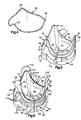
- FIG. 1 illustrates a preferred embodiment of a natural tissue heart valve, generally indicated at 10.
- the heart valve 10 includes an inflow end 12, an outflow end 14 and a central axis, indicated at A, extending through the inflow and outflow ends 12 and 14, respectively.
- the valve 10 also has a generally cylindrical side wall portion 16 formed of a valve wall extending between the inflow end 12 and the outflow end 14.
- the heart valve 10 also includes a plurality of leaflets or cusps 18, 20 and 22 mounted within the side wall portion 16. Each of the leaflets 18, 20 and 22 has a respective associated side wall portion 24, 26 and 28 and respective pairs of opposed side edges 30 and 32, 34 and 36 and 38 and 40.
- the heart valve 10 comprises also sinuses 48, 50 and 52 formed in the outflow end 14 of the valve 10 between adjacent commissures 42 and 44, 44 and 46, and 46 and 42, respectively.
- the heart valve illustrated in Fig. 1 is a tri-composite natural tissue heart valve.
- each of the leaflets 18, 20 and 22 are selected to be of similar size, shape and symmetry. Matching the leaflets 18, 20 and 22 in this manner generally provides an improved operation of the tri-composite valve over complete heart valves, which have asymmetric valve leaflets.
- each of the leaflets 18, 20 and 22 is a non-coronary leaflet, suitably from an aortic porcine valve.
- Non-coronary leaflets generally experience enhanced durability because of the fibrous attachment of each leaflet 18, 20 and 22 to its respective valve wall portion 24, 26 and 28.
- the leaflets 18, 20 and 22 and associated valve wall portions 24, 26 and 28 may be excised from an appropriate valve, which has been tanned or fixed.
- a valve may be fixed in a 0.3 to 0.5 glutaraldehyde solution at a temperature ranging between about 15°C and 25°C.
- a pressure between 0 and 0.53kPa (0 and 4 millimeters mercury (HG)) may also be applied to the outflow end of a valve to maintain the leaflets in a desired closed position.
- the side edges 30 and 32, 34 and 36, and 38 and 40 of the associated valve wall portion 24, 26 and 28 of each respective leaflet 18, 20 and 22 of the composite heart valve 10 are attached, suitably by sutures, to the side edges of each adjacent associated leaflet, as shown in Fig. 1.
- the tri-composite heart valve 10 should be assembled such that there is substantial coaptation, or generally axial engagement along the axis A, between each of the leaflets 18, 20 and 22 when in the closed position. This arrangement provides for substantially simultaneous opening and closing of the leaflets 18, 20 and 22 to permit blood flow through the valve 10 as well as to inhibit blood backflow.
- the composite heart valve 10 is similar in appearance and operation to a complete heart valve.
- a complete heart valve such as an aortic porcine valve or other suitable heart valve, may also be used in connection with the present invention.
- annular ring 60 is positioned around the valve wall 16 intermediate the inflow and outflow ends 12 and 14, respectively.
- Three alternative embodiments of suitable rings 60, 70 and 80 are illustrated in Figs. 2, 3 and 4, respectively.
- Each of the rings 60, 70 and 80 is formed of a substantially flexible and resilient material, preferably having maximum memory to return to its original shape after being stressed. In general, the ring 60, 70 and 80 stabilizes the heart valve prosthesis during implantation.
- the ring 60, 70 or 80 also has a known outer diameter, suitably ranging in a variety of predetermined sizes. This provides an practical and accurate way to determine the size of the resulting prosthesis. Based upon the size of the ring 60, 70 or 80, a surgeon may select an appropriately sized prosthesis for implantation without a significant likelihood of a sizing mismatch between the prosthesis and the patient.
- the ring 60 illustrated in Fig. 2 is formed of a synthetic resin material, which may be a plastic material, such as DelrinTM.
- the ring 60 has a radial thickness of less than about 0.5 millimeters.
- the ring 60 also has an inner diameter that approximates the outer diameter of the heart valve 10 to which it is attached, such that the ring 60 engages the side wall portion 16.
- the ring 60 has an outflow edge 62 dimensioned and configured according to the contour of the outflow end 14 of the valve 10.
- the outflow edge 62 of the ring 60 is sinusoidal having peaks 66, 67 and 68 that are spaced apart circumferentially to correspond to the circumferential positioning and shape of the commissures 42, 44 and 46.
- the axial length of the ring 60 at the peaks 66, 67 and 68 is from about 1 / 3 to about 2 / 3 the axial length of the valve 10 along the respective commissures 42, 44 and 46.
- the ring 60 also has inflow edge 64 contoured according to the inflow end 12 of the valve 10.
- the ring 60 is positioned coaxially around the valve 10, such as by sliding it over the side wall portion 16.
- the ring 60 is positioned intermediate the inflow and outflow ends 12 and 14, respectively, as shown in Fig. 5.
- the respective inflow and outflow edges 64 and 62 of the ring preferably are spaced apart from the respective inflow and outflow ends 12 and 14 of the valve 10.
- the peaks 66, 67 and 68 are aligned with the respective commissures 42, 44 and 46.
- one or more sutures 69 may be applied to secure the ring 60 to the side wall portion 16 of the valve 10.
- the ring 70 includes an outflow edge 72 and an inflow edge 74, which are dimensioned and configured to correspond to the contour of the respective outflow end 14 and inflow end 12 of the heart valve 10 to which it is to be attached.
- the outflow edge 72 of the ring 70 is preferably sinusoidal, with peaks 76, 77 and 78 dimensioned and configured according to the commissures 42, 44 and 46 of the valve 10.
- the ring 70 is formed of two spaced apart layers 71 and 73 of thin, flexible and resilient wire.
- a plurality of axially extending connecting rods 75 are connected between the layers 71 and 73 to maintain the spaced apart relationship of the layers 71 and 73.
- the annular ring 80 shown in Fig. 4 is formed of a single layer of a thin, flexible and resilient wire.
- the single layer ring 80 is dimensioned and configured to correspond to the dimensions and configuration of the outflow end 14 of the valve 10 to which it is to be attached.
- the ring 80 includes peaks 82, 84 and 86 dimensioned and spaced according to the commissures 42, 44 and 46 of the valve 10.
- the double layer ring 70 and the single layer ring 80 are attached to a heart valve 10 in a manner substantially identical to that shown and described with respect to Fig. 5.
- Each ring 70 or 80 will be positioned around the outer surface of the valve wall 16 with the peaks 76, 77 and 78 or 82, 84 and 86 of the ring 70 or 80 aligned with a respective commissure 42, 44 and 46.
- the rings 70 or 80 should be positioned intermediate the respective outflow and inflow ends 14 and 12 of the valve 10, such as is shown in Fig. 5 for the ring 60.
- the rings 70 or 80 may be secured to the side wall portion 16 of the valve 10, suitably by one or more sutures.
- each respective ring 60, 70 or 80 will be substantially symmetrical for a tri-composite valve, such as shown in Fig. 1, and asymmetrical for a complete valve (not shown).
- a preferred embodiment of a heart valve prosthesis 88 in accordance with the present invention is illustrated in Fig. 6.
- a thin sheath 90 of natural tissue is applied over and covers the ring 60 and the side wall portion 16 of the valve 10.
- the sheath 90 preferably is formed of pericardium, suitably porcine or equine pericardium which has been appropriately fixed in a glutaraldehyde solution.
- the sheath 90 has an inflow end portion 92 that extends beyond the inflow end 12 of the heart valve 10 to define an implantation flange, indicated at 94.
- the sheath 90 also includes an outflow end portion 96 having a plurality of ear-shaped flanges or lobes 98, 100 and 102 extending beyond the outflow end 14 of the valve 10.
- the lobes 98, 100 and 102 extend a predetermined distance beyond and lateral to each of the commissures 42, 44 and 46 at the outflow end 14 of the valve 10.
- the lobes 98, 100 and 102 preferably extend from about three to about four millimeters above the respective commissures and 42, 44 and 46.
- the lobes 98, 100 and 102 might also extend a greater distance beyond each respective commissure 42, 44 and 46.
- the surgeon implanting the prosthesis 88 may thus cut the lobes 98, 100 and 102 to a desired shape and size.
- the particular size of the lobes 98, 100 and 102 also will depend upon the size of the prosthesis 88.
- the outflow end 96 of the sheath 90 also follows the contour of the valve sinuses 48, 50 and 52.
- the sheath 90 is secured to outflow end 14 of the valve 10, such as by a plurality of sutures 104.
- the inflow end 12 of the valve 10 may be secured to the sheath 90 by sutures 105.
- the lobes 98, 100 and 102 may conveniently be sewn to the aortic valve wall of the patient. Consequently, the aortic valve wall of the patient will inhibit the inward deflection of the commissures 42, 44 and 46, thereby maintaining a desired shape of the prosthesis 88.
- the ring 60, 70 or 80 configured to be substantially flexible, such that the ring cannot of its own strength inhibit the deflection of the commissures 42, 44 and 46 during closure of the leaflets 18, 20 and 22.
- the sheath 90 also includes a pair of side edges that are secured edge to edge, suitably by sutures, to form an axial seam 108.
- the seam 108 preferably is positioned in the middle of one leaflet 28 intermediate adjacent commissures 42 and 46.
- the sheath 90 also is secured about the ring 60, such as by sutures 106 sewn through the sheath 90 and through the side wall portion of the 16 of the valve along the inflow and outflow edges 62 and 64 of the ring 60.
- sutures 106 sewn through the sheath 90 and through the side wall portion of the 16 of the valve along the inflow and outflow edges 62 and 64 of the ring 60.
- "mattress sutures" 106 between the sheath 90 and the ring 60 are used to maintain the axial positioning of the ring 60 intermediate the inflow and outflow ends 12 and 14 of the heart valve 10, as shown in Fig. 6.
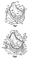
- FIG. 8 An alternative embodiment of a heart valve prosthesis 128 is shown in Fig. 8.
- Fig. 7 illustrates an intermediate step in the fabrication process of the prosthesis 128 of Fig. 8.
- the prosthesis 128 includes a natural tissue heart valve 130, which may be substantially similar to the valve 10 shown and described with respect to Fig. 1.
- the heart valve 130 may be a complete heart valve or a composite heart valve, although a composite valve is preferred.
- the heart valve 130 includes an inflow end 132, an outflow end 134 and a generally cylindrical side wall portion 136 extending between the inflow end 132 and the outflow end 134.
- the side wall portion 136 is defined by the valve wall portion of the heart valve 10.
- the heart valve has an axis, indicated at B, extending through the inflow and outflow ends 132 and 134, respectively.
- the composite heart valve 130 also includes a plurality of similarly sized, similarly shaped and symmetrical leaflets 138, 140 and 142. Each leaflet 138, 140 and 142 has an associated side wall portion 144, 146 and 148, respectively, which define the side wall portion 136.
- adjacent leaflets 138, 140 and 142 are attached at their adjacent side edges of the side wall portions 144, 146 and 148, suitably by suture, to define commissures, indicated at 150, 152 and 154.
- the heart valve 130 also includes sinuses 151, 153, and 155 formed in the outflow end 134 of the valve 130 between adjacent respective commissures 150 and 152, 152 and 154, and 154 and 150.
- the prosthesis 128 includes a first sheath 160 of natural tissue, such as a thin sheet of equine or porcine pericardium, covering the outer surface of the valve 130 intermediate the inflow and outflow end portions 132 and 134, respectively.
- the first sheath 160 is secured to the side wall portion 136, suitably by sutures (not shown), along at least a portion of the inflow and outflow ends 132 and 134 of the valve 130.
- the first sheath 160 covers substantially the entire side wall portion 136 of the valve 130, as shown in Fig. 7.
- An annular ring 162 which, for example, can be one of the rings 60, 70 and 80 shown and described with respect to Figs. 2, 3 and 4, is positioned coaxially around the first sheath 160 and the valve 130 and intermediate the inflow and outflow ends 132 and 134 of the valve 130.
- the ring 162 includes an outflow end 164 dimensioned and configured according to the contour of the outflow end 134 of the valve 130. More particularly, the ring 162 has a sinusoidal outflow end 164 having peaks 166 and 170 spaced circumferentially to correspond to the respective commissures 150 and 154.
- the ring 162 also includes an inflow end 165 contoured according to the inflow end 132 of the valve 130.
- the ring 162 is positioned around the valve 130, such that the axial length of the ring 162 at the peaks 166 and 170 extends from about 1 / 3 to about 2 / 3 the axial length of the heart valve 130 at the respective commissures 150 and 154.
- the ring 162 may be secured to the first sheath 160 by one or more sutures, indicated at 171. This will maintain a desired axial position of the ring 162 until additional sutures may be applied as described below.
- the outer sheath 172 has an inflow end portion 174 that extends beyond the inflow end 132 of the heart valve 130 to define an implantation flange, indicated at 176.
- the outer sheath 172 also includes an outflow end portion 178 having a plurality of lobes 182, 184 and 186 extending beyond the outflow end 134 of the valve 130.
- the lobes 182, 184 and 186 which may be ear-shaped flanges, preferably extend a predetermined distance beyond and lateral to each of the commissures 150, 152 and 154 at the outflow end 134 of the valve 130.
- the outflow end portion 178 of the outer sheath 172 also follows the contour of the sinuses 151, 153 and 155 intermediate each of the commissures 150, 152 and 154.
- the outer sheath 172 is secured to the valve 130 and the inner sheath 160 along the inflow and outflow ends 132 and 134 of the valve 130, suitably by respective sutures 179 and 180.
- the lobes 182, 184 and 186 may conveniently be sewn to the aortic valve wall of the patient, thereby. inhibiting the inward deflection of the commissures 150, 152 and 154 during operation of the prosthesis 128.
- the outer sheath 172 includes an axial seam 188, which is formed by suturing its ends together.
- the seam 188 preferably is positioned in the middle of one leaflet 142 between adjacent commissures 150 and 154.
- the outer sheath 172 also is secured to the side wall portion 136 of the valve 130 and about the ring 162, such as by "mattress sutures" 190.
- the sutures 190 maintain the axial positioning of the ring 162 spaced apart from and intermediate the respective inflow and outflow ends 132 and 134 of the heart valve 130.
- the present invention provides an improved heart valve prosthesis 88 or 128, which may be termed "semi-stentless.”
- the prosthesis 88 or 128 exhibits hemodynamics comparable to known stentless valves.
- the flexible ring 60, 70, 80 or 162 provides a "skeleton" to stabilize the prosthesis 88 or 128, without significantly increasing its side wall thickness.
- the ring 60, 70, 80 or 162 also will resist deformation of the prosthesis 88 or 128 and promote desired coaptation of the leaflets 18, 20 and 22 or 138, 140 and 142.
- the prosthesis 88 or 128 exposes only natural tissue and sutures, thereby providing biocompatibility with the patient.
Abstract
Description
Claims (13)
- A heart valve prosthesis (88, 128) comprising:a natural tissue heart valve (10, 130) having an inflow end (12, 132), an outflow end (14, 134) and a generally cylindrical side wall portion (16) extending between said inflow end and said outflow end, said valve including a plurality of leaflets (18, 20, 22), each of said leaflets having an associated side wall portion (24, 26, 28), said leaflets and adjacent portions of respective said associated side wall portions (24, 26, 28) defining commissures (42, 44, 46);an annular ring (60, 70, 80) of a substantially flexible material positioned around said valve wall intermediate said inflow and outflow ends; anda sheath (90, 172) of natural tissue attached around said valve wall (16) and said ring (60, 70, 80), said sheath (90, 172) having an inflow end (92, 174) extending beyond said inflow end (12, 132) of said heart valve and defining an implantation flange (94), said sheath having an outflow end (96, 178) with a plurality of lobes (98, 100, 102, 182, 184, 186) extending beyond said outflow end (14, 134) of said heart valve.
- A heart valve prosthesis (88, 128) as claimed in claim 1 wherein each of said leaflets (18, 20, 22) has side edges (30, 32, 34, 36, 38, 40); adjacent side edges of adjacent said leaflets and adjacent portions of respective said associated side wall portions (24, 26, 28) defining said commissures (42, 44, 46).
- A heart valve prosthesis as claimed in claim 1 or claim 2 wherein said sheath (90, 172) is made of pericardium.
- A heart valve prosthesis as claimed in any preceeding claim wherein said heart valve comprises a composite heart valve formed of three heart valve leaflets (18, 20, 22) of generally similar size, shape and symmetry, each said leaflet including a valve wall portion (24, 26, 28) having an inflow end (12, 132), an outflow end (14, 174) and a pair of generally opposed side edges (30 and 40, 32 and 34, 36 and 38) extending between the inflow (12, 132) and outflow (14, 134) ends, said side edges of each of said leaflets being attached to said side edges of adjacent leaflets such that there is substantial coaptation between said leaflets, adjacent side edges of adjacent leaflets defining said commissures (42, 44, 46) and said valve wall portions of said composite heart valve leaflets defining said side wall portion (16) of said heart valve.
- A heart valve prosthesis as claimed in claim 4 wherein each of said leaflets (18, 20, 22) is a non-coronary leaflet of an aortic heart valve.
- A heart valve prosthesis as claimed in any proceeding claim wherein said ring (60, 70, 80) comprises a plastic material having a substantially thin side wall portion.
- A heart valve prosthesis as claimed in any of claims 1 to 5 wherein said ring (60, 70, 80) comprises a resilient thin wire member.
- A heart valve prosthesis (88, 128) comprising:a natural tissue heart valve (10, 130) comprising:a generally cylindrical side wall portion (16) extending between an inflow end (12, 132) and an outflow end (14,134), said side wall portion (16) having an outer surface; anda plurality of leaflets (18, 20, 22) disposed within said side wall portion (16), each of said leaflets (18, 20, 22) having an associated side wall portion (24, 26, 28), adjacent said leaflets (18, 20, 22) and respective adjacent portions of said associated side wall portions defining commissures (42, 44, 46);an outer sheath (90, 172) of natural tissue covering said outer surface of said heart valve, said outer sheath (90, 172) having an outflow end portion (96, 178) extending beyond said outflow end (14, 134) of said heart valve (10, 130) adjacent said commissures (42, 44, 46) to define a plurality of lobes (98, 100, 102, 182, 184, 186).
- A heart valve prosthesis (88, 128) as claimed in claim 8 wherein each of said leaflets (18, 20, 22) has side edges (30, 32, 34, 36, 38, 40); adjacent side edges of adjacent said leaflets (18, 20, 22) and respective adjacent portions of said associated side wall portions defining said commissures (42, 44, 46).
- A heart valve prosthesis as claimed in claim 8 or claim 9 further comprising a substantially flexible annular ring (60, 70, 80) positioned around said outer surface of said side wall portion (16) spaced from and intermediate said outflow end (14, 134) of said heart valve (10, 130), said outer sheath (90, 172) covering said ring, (60, 70, 80) and said heart valve (10, 130).
- A heart valve prosthesis as claimed in claim 10 further comprising a second sheath (160) of natural tissue covering said side wall portion of said heart valve intermediate said ring (60, 70, 80) and said heart valve (10, 130), said second sheath (160) extending between said inflow (12, 132) and outflow (14, 134) ends of said heart valve.
- A method of making a heart valve prosthesis comprising the steps of:providing a heart valve (10, 130) having an inflow end (12, 132), an outflow end (14, 134), a generally cylindrical side wall portion (16) extending between said inflow end (12, 132) and said outflow end (14, 134), said heart valve (10, 130) including a plurality of leaflets (18, 20, 22) disposed within said side wall portion (16), each of said leaflets having an associated side wall portion (24, 26, 28), adjacent said leaflets (18, 20, 22) and respective adjacent portions of said associated side wall portions defining commissures (42, 44, 46);positioning an annular ring (60, 70, 80) of a substantially flexible and resilient material around said side wall portion (16) intermediate said inflow (12, 132) and outflow (14, 134) ends of said heart valve (10, 130);covering said annular ring (60, 70, 80) and said outer surface of said heart valve with a sheath (90, 172) of natural tissue, said sheath (90, 172) having an inflow end (92, 174) portion and an outflow end portion (96); andextending said outflow end portion (96) of said sheath (90) beyond said outflow end (14, 134) of said heart valve (10, 130) to define a plurality of lobes (98, 100, 102, 182, 184, 186) adjacent said commissures (42, 44, 46).
- A method as claimed in claim 12 wherein each of said leaflets (18, 20, 22) has a pair of side edges (30, 32, 34, 36, 38, 40); adjacent side edges of adjacent said leaflets (18, 20, 22) and respective adjacent portions of said associated side wall portions defining said commissures (42, 44, 46).
Applications Claiming Priority (3)
| Application Number | Priority Date | Filing Date | Title |
|---|---|---|---|
| US09/052,707 US5935163A (en) | 1998-03-31 | 1998-03-31 | Natural tissue heart valve prosthesis |
| US52707 | 1998-03-31 | ||
| PCT/US1999/006406 WO1999049817A1 (en) | 1998-03-31 | 1999-03-24 | Natural tissue heart valve prosthesis |
Publications (3)
| Publication Number | Publication Date |
|---|---|
| EP0986348A1 EP0986348A1 (en) | 2000-03-22 |
| EP0986348A4 EP0986348A4 (en) | 2001-07-25 |
| EP0986348B1 true EP0986348B1 (en) | 2002-09-04 |
Family
ID=21979385
Family Applications (1)
| Application Number | Title | Priority Date | Filing Date |
|---|---|---|---|
| EP99912867A Expired - Lifetime EP0986348B1 (en) | 1998-03-31 | 1999-03-24 | Natural tissue heart valve prosthesis |
Country Status (8)
| Country | Link |
|---|---|
| US (1) | US5935163A (en) |
| EP (1) | EP0986348B1 (en) |
| AT (1) | ATE223182T1 (en) |
| DE (1) | DE69902727T2 (en) |
| DK (1) | DK0986348T3 (en) |
| ES (1) | ES2183529T3 (en) |
| PT (1) | PT986348E (en) |
| WO (1) | WO1999049817A1 (en) |
Cited By (24)
| Publication number | Priority date | Publication date | Assignee | Title |
|---|---|---|---|---|
| US7704222B2 (en) | 1998-09-10 | 2010-04-27 | Jenavalve Technology, Inc. | Methods and conduits for flowing blood from a heart chamber to a blood vessel |
| US7896913B2 (en) | 2000-02-28 | 2011-03-01 | Jenavalve Technology, Inc. | Anchoring system for implantable heart valve prostheses |
| US7896915B2 (en) | 2007-04-13 | 2011-03-01 | Jenavalve Technology, Inc. | Medical device for treating a heart valve insufficiency |
| US8062355B2 (en) | 2005-11-04 | 2011-11-22 | Jenavalve Technology, Inc. | Self-expandable medical instrument for treating defects in a patient's heart |
| US8092521B2 (en) | 2005-10-28 | 2012-01-10 | Jenavalve Technology, Inc. | Device for the implantation and fixation of prosthetic valves |
| US8206437B2 (en) | 2001-08-03 | 2012-06-26 | Philipp Bonhoeffer | Implant implantation unit and procedure for implanting the unit |
| US8317858B2 (en) | 2008-02-26 | 2012-11-27 | Jenavalve Technology, Inc. | Stent for the positioning and anchoring of a valvular prosthesis in an implantation site in the heart of a patient |
| US8398704B2 (en) | 2008-02-26 | 2013-03-19 | Jenavalve Technology, Inc. | Stent for the positioning and anchoring of a valvular prosthesis in an implantation site in the heart of a patient |
| US8465540B2 (en) | 2008-02-26 | 2013-06-18 | Jenavalve Technology, Inc. | Stent for the positioning and anchoring of a valvular prosthesis |
| US8468667B2 (en) | 2009-05-15 | 2013-06-25 | Jenavalve Technology, Inc. | Device for compressing a stent |
| US8679174B2 (en) | 2005-01-20 | 2014-03-25 | JenaValve Technology, GmbH | Catheter for the transvascular implantation of prosthetic heart valves |
| USRE45130E1 (en) | 2000-02-28 | 2014-09-09 | Jenavalve Technology Gmbh | Device for fastening and anchoring cardiac valve prostheses |
| US9044318B2 (en) | 2008-02-26 | 2015-06-02 | Jenavalve Technology Gmbh | Stent for the positioning and anchoring of a valvular prosthesis |
| US9138315B2 (en) | 2007-04-13 | 2015-09-22 | Jenavalve Technology Gmbh | Medical device for treating a heart valve insufficiency or stenosis |
| US9168130B2 (en) | 2008-02-26 | 2015-10-27 | Jenavalve Technology Gmbh | Stent for the positioning and anchoring of a valvular prosthesis in an implantation site in the heart of a patient |
| US9295551B2 (en) | 2007-04-13 | 2016-03-29 | Jenavalve Technology Gmbh | Methods of implanting an endoprosthesis |
| US9510947B2 (en) | 2011-10-21 | 2016-12-06 | Jenavalve Technology, Inc. | Catheter system for introducing an expandable heart valve stent into the body of a patient |
| US9597182B2 (en) | 2010-05-20 | 2017-03-21 | Jenavalve Technology Inc. | Catheter system for introducing an expandable stent into the body of a patient |
| US9744031B2 (en) | 2010-05-25 | 2017-08-29 | Jenavalve Technology, Inc. | Prosthetic heart valve and endoprosthesis comprising a prosthetic heart valve and a stent |
| US9867699B2 (en) | 2008-02-26 | 2018-01-16 | Jenavalve Technology, Inc. | Endoprosthesis for implantation in the heart of a patient |
| US9867694B2 (en) | 2013-08-30 | 2018-01-16 | Jenavalve Technology Inc. | Radially collapsible frame for a prosthetic valve and method for manufacturing such a frame |
| US9878127B2 (en) | 2012-05-16 | 2018-01-30 | Jenavalve Technology, Inc. | Catheter delivery system for heart valve prosthesis |
| US10709555B2 (en) | 2015-05-01 | 2020-07-14 | Jenavalve Technology, Inc. | Device and method with reduced pacemaker rate in heart valve replacement |
| US11278406B2 (en) | 2010-05-20 | 2022-03-22 | Jenavalve Technology, Inc. | Catheter system for introducing an expandable heart valve stent into the body of a patient, insertion system with a catheter system and medical device for treatment of a heart valve defect |
Families Citing this family (190)
| Publication number | Priority date | Publication date | Assignee | Title |
|---|---|---|---|---|
| US7722667B1 (en) * | 1998-04-20 | 2010-05-25 | St. Jude Medical, Inc. | Two piece bioprosthetic heart valve with matching outer frame and inner valve |
| JP2002518131A (en) | 1998-06-24 | 2002-06-25 | サルザー カーボメディクス インコーポレイテッド | A heart valve leaflet coupling structure that changes to affect the location and magnitude of the maximum load pressure on the leaflet |
| US6334873B1 (en) * | 1998-09-28 | 2002-01-01 | Autogenics | Heart valve having tissue retention with anchors and an outer sheath |
| US6558418B2 (en) | 1999-01-26 | 2003-05-06 | Edwards Lifesciences Corporation | Flexible heart valve |
| US6736845B2 (en) | 1999-01-26 | 2004-05-18 | Edwards Lifesciences Corporation | Holder for flexible heart valve |
| US6364905B1 (en) * | 1999-01-27 | 2002-04-02 | Sulzer Carbomedics Inc. | Tri-composite, full root, stentless valve |
| US6660260B1 (en) | 1999-09-21 | 2003-12-09 | Mayo Foundation For Medical Education And Research | Bioprosthetic heart valves |
| US6371983B1 (en) * | 1999-10-04 | 2002-04-16 | Ernest Lane | Bioprosthetic heart valve |
| US8579966B2 (en) | 1999-11-17 | 2013-11-12 | Medtronic Corevalve Llc | Prosthetic valve for transluminal delivery |
| US7018406B2 (en) | 1999-11-17 | 2006-03-28 | Corevalve Sa | Prosthetic valve for transluminal delivery |
| DE60128069D1 (en) * | 2000-01-31 | 2007-06-06 | Cook Biotech Inc | STENT VALVE FLAP |
| AU2001256985B2 (en) * | 2000-04-06 | 2006-08-31 | Edwards Lifesciences Corporation | Minimally-invasive heart valves and methods of use |
| US6454799B1 (en) * | 2000-04-06 | 2002-09-24 | Edwards Lifesciences Corporation | Minimally-invasive heart valves and methods of use |
| US6610088B1 (en) * | 2000-05-03 | 2003-08-26 | Shlomo Gabbay | Biologically covered heart valve prosthesis |
| WO2001087190A2 (en) * | 2000-05-17 | 2001-11-22 | St. Jude Medical, Inc. | Two piece bioprosthetic heart valve |
| WO2002022054A1 (en) * | 2000-09-12 | 2002-03-21 | Gabbay S | Valvular prosthesis and method of using same |
| US7510572B2 (en) | 2000-09-12 | 2009-03-31 | Shlomo Gabbay | Implantation system for delivery of a heart valve prosthesis |
| US6461382B1 (en) * | 2000-09-22 | 2002-10-08 | Edwards Lifesciences Corporation | Flexible heart valve having moveable commissures |
| US6517576B2 (en) * | 2000-12-11 | 2003-02-11 | Shlomo Gabbay | Implantable patch prosthesis having one or more cusps for improved competency |
| US6733525B2 (en) | 2001-03-23 | 2004-05-11 | Edwards Lifesciences Corporation | Rolled minimally-invasive heart valves and methods of use |
| US6682558B2 (en) | 2001-05-10 | 2004-01-27 | 3F Therapeutics, Inc. | Delivery system for a stentless valve bioprosthesis |
| US6893460B2 (en) | 2001-10-11 | 2005-05-17 | Percutaneous Valve Technologies Inc. | Implantable prosthetic valve |
| US7201771B2 (en) * | 2001-12-27 | 2007-04-10 | Arbor Surgical Technologies, Inc. | Bioprosthetic heart valve |
| US7189258B2 (en) * | 2002-01-02 | 2007-03-13 | Medtronic, Inc. | Heart valve system |
| US7033390B2 (en) * | 2002-01-02 | 2006-04-25 | Medtronic, Inc. | Prosthetic heart valve system |
| US7351256B2 (en) * | 2002-05-10 | 2008-04-01 | Cordis Corporation | Frame based unidirectional flow prosthetic implant |
| CA2485285A1 (en) * | 2002-05-10 | 2003-11-20 | Cordis Corporation | Method of making a medical device having a thin wall tubular membrane over a structural frame |
| US7485141B2 (en) * | 2002-05-10 | 2009-02-03 | Cordis Corporation | Method of placing a tubular membrane on a structural frame |
| US7270675B2 (en) | 2002-05-10 | 2007-09-18 | Cordis Corporation | Method of forming a tubular membrane on a structural frame |
| US7959674B2 (en) | 2002-07-16 | 2011-06-14 | Medtronic, Inc. | Suture locking assembly and method of use |
| US20040024452A1 (en) * | 2002-08-02 | 2004-02-05 | Kruse Steven D. | Valved prostheses with preformed tissue leaflets |
| US8551162B2 (en) | 2002-12-20 | 2013-10-08 | Medtronic, Inc. | Biologically implantable prosthesis |
| DE10301023A1 (en) * | 2003-01-13 | 2004-07-22 | Medos Medizintechnik Ag | Implant, in particular ring for heart valve, designed in curved and asymmetric shape |
| US7399315B2 (en) | 2003-03-18 | 2008-07-15 | Edwards Lifescience Corporation | Minimally-invasive heart valve with cusp positioners |
| US7374488B2 (en) * | 2003-04-17 | 2008-05-20 | Atronic Systems G.M.B.H. | Player insert for a gaming machine, a gaming system and a method of operating a gaming system |
| US20050038509A1 (en) * | 2003-08-14 | 2005-02-17 | Ashe Kassem Ali | Valve prosthesis including a prosthetic leaflet |
| US8021421B2 (en) | 2003-08-22 | 2011-09-20 | Medtronic, Inc. | Prosthesis heart valve fixturing device |
| US7556647B2 (en) | 2003-10-08 | 2009-07-07 | Arbor Surgical Technologies, Inc. | Attachment device and methods of using the same |
| US7347869B2 (en) | 2003-10-31 | 2008-03-25 | Cordis Corporation | Implantable valvular prosthesis |
| US7070616B2 (en) * | 2003-10-31 | 2006-07-04 | Cordis Corporation | Implantable valvular prosthesis |
| CA2556077C (en) * | 2004-02-05 | 2012-05-01 | Children's Medical Center Corporation | Transcatheter delivery of a replacement heart valve |
| US7247167B2 (en) * | 2004-02-19 | 2007-07-24 | Shlomo Gabbay | Low profile heart valve prosthesis |
| US7758638B2 (en) | 2004-07-13 | 2010-07-20 | Ats Medical, Inc. | Implant with an annular base |
| US20060047296A1 (en) * | 2004-08-31 | 2006-03-02 | Sdg Holdings, Inc. | Annulus replacement system and technique |
| US20060195186A1 (en) * | 2005-02-28 | 2006-08-31 | Drews Michael J | Connectors for two piece heart valves and methods for implanting such heart valves |
| US8083793B2 (en) | 2005-02-28 | 2011-12-27 | Medtronic, Inc. | Two piece heart valves including multiple lobe valves and methods for implanting them |
| US8062359B2 (en) * | 2005-04-06 | 2011-11-22 | Edwards Lifesciences Corporation | Highly flexible heart valve connecting band |
| US7513909B2 (en) * | 2005-04-08 | 2009-04-07 | Arbor Surgical Technologies, Inc. | Two-piece prosthetic valves with snap-in connection and methods for use |
| WO2006130505A2 (en) | 2005-05-27 | 2006-12-07 | Arbor Surgical Technologies, Inc. | Gasket with collar for prosthetic heart valves and methods for using them |
| US7739971B2 (en) * | 2005-06-07 | 2010-06-22 | Edwards Lifesciences Corporation | Systems and methods for assembling components of a fabric-covered prosthetic heart valve |
| US20070213813A1 (en) | 2005-12-22 | 2007-09-13 | Symetis Sa | Stent-valves for valve replacement and associated methods and systems for surgery |
| US7967857B2 (en) | 2006-01-27 | 2011-06-28 | Medtronic, Inc. | Gasket with spring collar for prosthetic heart valves and methods for making and using them |
| JP2009535128A (en) | 2006-04-29 | 2009-10-01 | アーバー・サージカル・テクノロジーズ・インコーポレイテッド | Multi-part prosthetic heart valve assembly and apparatus and method for delivering the same |
| WO2007130537A1 (en) * | 2006-05-05 | 2007-11-15 | Children's Medical Center Corporation | Transcatheter heart valve prostheses |
| ES2384199T3 (en) | 2007-08-24 | 2012-07-02 | St. Jude Medical, Inc. | Prosthetic aortic heart valves |
| US8273118B2 (en) * | 2007-09-17 | 2012-09-25 | Medtronic, Inc. | Heart valve holder assembly for use in valve implantation procedures |
| AU2008305600B2 (en) | 2007-09-26 | 2013-07-04 | St. Jude Medical, Inc. | Collapsible prosthetic heart valves |
| WO2009045334A1 (en) | 2007-09-28 | 2009-04-09 | St. Jude Medical, Inc. | Collapsible/expandable prosthetic heart valves with native calcified leaflet retention features |
| US9532868B2 (en) | 2007-09-28 | 2017-01-03 | St. Jude Medical, Inc. | Collapsible-expandable prosthetic heart valves with structures for clamping native tissue |
| US9241792B2 (en) * | 2008-02-29 | 2016-01-26 | Edwards Lifesciences Corporation | Two-step heart valve implantation |
| ES2584315T3 (en) | 2008-07-15 | 2016-09-27 | St. Jude Medical, Inc. | Collapsible and re-expandable prosthetic heart valve sleeve designs and complementary technological applications |
| JP5659168B2 (en) | 2009-02-27 | 2015-01-28 | セント・ジュード・メディカル,インコーポレイテッド | Foldable prosthetic heart valve stent features |
| WO2011159342A1 (en) | 2010-06-17 | 2011-12-22 | St. Jude Medical, Inc. | Collapsible heart valve with angled frame |
| US9039759B2 (en) | 2010-08-24 | 2015-05-26 | St. Jude Medical, Cardiology Division, Inc. | Repositioning of prosthetic heart valve and deployment |
| US8814931B2 (en) | 2010-08-24 | 2014-08-26 | St. Jude Medical, Cardiology Division, Inc. | Staged deployment devices and methods for transcatheter heart valve delivery systems |
| WO2012036741A2 (en) | 2010-09-17 | 2012-03-22 | St. Jude Medical, Cardiology Division, Inc. | Staged deployment devices and methods for transcatheter heart valve delivery |
| JP2013540484A (en) | 2010-09-20 | 2013-11-07 | セント・ジュード・メディカル,カーディオロジー・ディヴィジョン,インコーポレイテッド | Valve leaflet mounting device in foldable artificial valve |
| US8932343B2 (en) | 2011-02-01 | 2015-01-13 | St. Jude Medical, Cardiology Division, Inc. | Blunt ended stent for prosthetic heart valve |
| US9717593B2 (en) | 2011-02-01 | 2017-08-01 | St. Jude Medical, Cardiology Division, Inc. | Leaflet suturing to commissure points for prosthetic heart valve |
| GB2488530A (en) * | 2011-02-18 | 2012-09-05 | David J Wheatley | Heart valve |
| US9060860B2 (en) | 2011-08-18 | 2015-06-23 | St. Jude Medical, Cardiology Division, Inc. | Devices and methods for transcatheter heart valve delivery |
| US9480558B2 (en) * | 2011-12-05 | 2016-11-01 | Medtronic, Inc. | Transcatheter valve having reduced seam exposure |
| US9554902B2 (en) | 2012-06-28 | 2017-01-31 | St. Jude Medical, Cardiology Division, Inc. | Leaflet in configuration for function in various shapes and sizes |
| US9289292B2 (en) | 2012-06-28 | 2016-03-22 | St. Jude Medical, Cardiology Division, Inc. | Valve cuff support |
| US20140005776A1 (en) | 2012-06-29 | 2014-01-02 | St. Jude Medical, Cardiology Division, Inc. | Leaflet attachment for function in various shapes and sizes |
| US9615920B2 (en) | 2012-06-29 | 2017-04-11 | St. Jude Medical, Cardiology Divisions, Inc. | Commissure attachment feature for prosthetic heart valve |
| US9241791B2 (en) | 2012-06-29 | 2016-01-26 | St. Jude Medical, Cardiology Division, Inc. | Valve assembly for crimp profile |
| US9808342B2 (en) | 2012-07-03 | 2017-11-07 | St. Jude Medical, Cardiology Division, Inc. | Balloon sizing device and method of positioning a prosthetic heart valve |
| US10004597B2 (en) | 2012-07-03 | 2018-06-26 | St. Jude Medical, Cardiology Division, Inc. | Stent and implantable valve incorporating same |
| US9283072B2 (en) | 2012-07-25 | 2016-03-15 | W. L. Gore & Associates, Inc. | Everting transcatheter valve and methods |
| US9801721B2 (en) | 2012-10-12 | 2017-10-31 | St. Jude Medical, Cardiology Division, Inc. | Sizing device and method of positioning a prosthetic heart valve |
| US10524909B2 (en) | 2012-10-12 | 2020-01-07 | St. Jude Medical, Cardiology Division, Inc. | Retaining cage to permit resheathing of a tavi aortic-first transapical system |
| US10039638B2 (en) | 2012-12-19 | 2018-08-07 | W. L. Gore & Associates, Inc. | Geometric prosthetic heart valves |
| US9737398B2 (en) | 2012-12-19 | 2017-08-22 | W. L. Gore & Associates, Inc. | Prosthetic valves, frames and leaflets and methods thereof |
| US9144492B2 (en) | 2012-12-19 | 2015-09-29 | W. L. Gore & Associates, Inc. | Truncated leaflet for prosthetic heart valves, preformed valve |
| US9968443B2 (en) | 2012-12-19 | 2018-05-15 | W. L. Gore & Associates, Inc. | Vertical coaptation zone in a planar portion of prosthetic heart valve leaflet |
| US9101469B2 (en) | 2012-12-19 | 2015-08-11 | W. L. Gore & Associates, Inc. | Prosthetic heart valve with leaflet shelving |
| US10966820B2 (en) | 2012-12-19 | 2021-04-06 | W. L. Gore & Associates, Inc. | Geometric control of bending character in prosthetic heart valve leaflets |
| CN103006352B (en) * | 2012-12-24 | 2015-05-13 | 杭州启明医疗器械有限公司 | Prosthesis valve and prosthesis valve device |
| US9186238B2 (en) | 2013-01-29 | 2015-11-17 | St. Jude Medical, Cardiology Division, Inc. | Aortic great vessel protection |
| US9314163B2 (en) | 2013-01-29 | 2016-04-19 | St. Jude Medical, Cardiology Division, Inc. | Tissue sensing device for sutureless valve selection |
| US9655719B2 (en) | 2013-01-29 | 2017-05-23 | St. Jude Medical, Cardiology Division, Inc. | Surgical heart valve flexible stent frame stiffener |
| US9901470B2 (en) | 2013-03-01 | 2018-02-27 | St. Jude Medical, Cardiology Division, Inc. | Methods of repositioning a transcatheter heart valve after full deployment |
| US9844435B2 (en) | 2013-03-01 | 2017-12-19 | St. Jude Medical, Cardiology Division, Inc. | Transapical mitral valve replacement |
| US9480563B2 (en) | 2013-03-08 | 2016-11-01 | St. Jude Medical, Cardiology Division, Inc. | Valve holder with leaflet protection |
| WO2014143126A1 (en) | 2013-03-12 | 2014-09-18 | St. Jude Medical, Cardiology Division, Inc. | Self-actuating sealing portions for paravalvular leak protection |
| US9636222B2 (en) | 2013-03-12 | 2017-05-02 | St. Jude Medical, Cardiology Division, Inc. | Paravalvular leak protection |
| US9339274B2 (en) | 2013-03-12 | 2016-05-17 | St. Jude Medical, Cardiology Division, Inc. | Paravalvular leak occlusion device for self-expanding heart valves |
| US9398951B2 (en) | 2013-03-12 | 2016-07-26 | St. Jude Medical, Cardiology Division, Inc. | Self-actuating sealing portions for paravalvular leak protection |
| US10314698B2 (en) | 2013-03-12 | 2019-06-11 | St. Jude Medical, Cardiology Division, Inc. | Thermally-activated biocompatible foam occlusion device for self-expanding heart valves |
| US10271949B2 (en) | 2013-03-12 | 2019-04-30 | St. Jude Medical, Cardiology Division, Inc. | Paravalvular leak occlusion device for self-expanding heart valves |
| US9326856B2 (en) | 2013-03-14 | 2016-05-03 | St. Jude Medical, Cardiology Division, Inc. | Cuff configurations for prosthetic heart valve |
| US9131982B2 (en) | 2013-03-14 | 2015-09-15 | St. Jude Medical, Cardiology Division, Inc. | Mediguide-enabled renal denervation system for ensuring wall contact and mapping lesion locations |
| US10321991B2 (en) | 2013-06-19 | 2019-06-18 | St. Jude Medical, Cardiology Division, Inc. | Collapsible valve having paravalvular leak protection |
| US9668856B2 (en) | 2013-06-26 | 2017-06-06 | St. Jude Medical, Cardiology Division, Inc. | Puckering seal for reduced paravalvular leakage |
| US9867611B2 (en) | 2013-09-05 | 2018-01-16 | St. Jude Medical, Cardiology Division, Inc. | Anchoring studs for transcatheter valve implantation |
| US10117742B2 (en) | 2013-09-12 | 2018-11-06 | St. Jude Medical, Cardiology Division, Inc. | Stent designs for prosthetic heart valves |
| US9414913B2 (en) | 2013-10-25 | 2016-08-16 | Medtronic, Inc. | Stented prosthetic heart valve |
| US9913715B2 (en) | 2013-11-06 | 2018-03-13 | St. Jude Medical, Cardiology Division, Inc. | Paravalvular leak sealing mechanism |
| US9700409B2 (en) | 2013-11-06 | 2017-07-11 | St. Jude Medical, Cardiology Division, Inc. | Reduced profile prosthetic heart valve |
| EP2870946B1 (en) | 2013-11-06 | 2018-10-31 | St. Jude Medical, Cardiology Division, Inc. | Paravalvular leak sealing mechanism |
| US9549818B2 (en) | 2013-11-12 | 2017-01-24 | St. Jude Medical, Cardiology Division, Inc. | Pneumatically power-assisted tavi delivery system |
| EP3071149B1 (en) | 2013-11-19 | 2022-06-01 | St. Jude Medical, Cardiology Division, Inc. | Sealing structures for paravalvular leak protection |
| EP3073964A1 (en) | 2013-11-27 | 2016-10-05 | St. Jude Medical, Cardiology Division, Inc. | Cuff stitching reinforcement |
| ES2771900T3 (en) | 2013-12-19 | 2020-07-07 | St Jude Medical Cardiology Div Inc | Valve-sleeve fixings for prosthetic heart valve |
| US9820852B2 (en) | 2014-01-24 | 2017-11-21 | St. Jude Medical, Cardiology Division, Inc. | Stationary intra-annular halo designs for paravalvular leak (PVL) reduction—active channel filling cuff designs |
| US20150209141A1 (en) | 2014-01-24 | 2015-07-30 | St. Jude Medical, Cardiology Division, Inc. | Stationary intra-annular halo designs for paravalvular leak (pvl) reduction-passive channel filling cuff designs |
| US9867556B2 (en) | 2014-02-07 | 2018-01-16 | St. Jude Medical, Cardiology Division, Inc. | System and method for assessing dimensions and eccentricity of valve annulus for trans-catheter valve implantation |
| US10292711B2 (en) | 2014-02-07 | 2019-05-21 | St. Jude Medical, Cardiology Division, Inc. | Mitral valve treatment device having left atrial appendage closure |
| EP3107496B1 (en) | 2014-02-18 | 2018-07-04 | St. Jude Medical, Cardiology Division, Inc. | Bowed runners for paravalvular leak protection |
| US9763778B2 (en) | 2014-03-18 | 2017-09-19 | St. Jude Medical, Cardiology Division, Inc. | Aortic insufficiency valve percutaneous valve anchoring |
| EP3119351B1 (en) | 2014-03-18 | 2021-10-20 | St. Jude Medical, Cardiology Division, Inc. | Mitral valve replacement toggle cell securement |
| EP3119352B1 (en) | 2014-03-21 | 2023-12-20 | St. Jude Medical, Cardiology Division, Inc. | Leaflet abrasion mitigation |
| CR20160424A (en) | 2014-03-26 | 2016-12-08 | St Jude Medical Cardiology Div Inc | Transcather mitral valve stent frames |
| WO2015152980A1 (en) | 2014-03-31 | 2015-10-08 | St. Jude Medical, Cardiology Division, Inc. | Paravalvular sealing via extended cuff mechanisms |
| EP3131504B1 (en) | 2014-04-14 | 2023-03-15 | St. Jude Medical, Cardiology Division, Inc. | Leaflet abrasion mitigation in prosthetic heart valves |
| US9668858B2 (en) | 2014-05-16 | 2017-06-06 | St. Jude Medical, Cardiology Division, Inc. | Transcatheter valve with paravalvular leak sealing ring |
| ES2795358T3 (en) | 2014-05-16 | 2020-11-23 | St Jude Medical Cardiology Div Inc | Subannular sealing for paravalvular leak protection |
| EP3142605A1 (en) | 2014-05-16 | 2017-03-22 | St. Jude Medical, Cardiology Division, Inc. | Stent assembly for use in prosthetic heart valves |
| US10500042B2 (en) | 2014-05-22 | 2019-12-10 | St. Jude Medical, Cardiology Division, Inc. | Stents with anchoring sections |
| EP2954875B1 (en) | 2014-06-10 | 2017-11-15 | St. Jude Medical, Cardiology Division, Inc. | Stent cell bridge for cuff attachment |
| CA2914094C (en) | 2014-06-20 | 2021-01-05 | Edwards Lifesciences Corporation | Surgical heart valves identifiable post-implant |
| USD867594S1 (en) * | 2015-06-19 | 2019-11-19 | Edwards Lifesciences Corporation | Prosthetic heart valve |
| BR112017003339A2 (en) | 2014-08-18 | 2017-11-28 | Gore & Ass | integral seamed structure for protective valves |
| US9808201B2 (en) | 2014-08-18 | 2017-11-07 | St. Jude Medical, Cardiology Division, Inc. | Sensors for prosthetic heart devices |
| EP3182927A1 (en) | 2014-08-18 | 2017-06-28 | St. Jude Medical, Cardiology Division, Inc. | Prosthetic heart devices having diagnostic capabilities |
| EP3182932B1 (en) | 2014-08-18 | 2019-05-15 | St. Jude Medical, Cardiology Division, Inc. | Annuloplasty ring with sensor |
| US9827094B2 (en) | 2014-09-15 | 2017-11-28 | W. L. Gore & Associates, Inc. | Prosthetic heart valve with retention elements |
| US10507101B2 (en) * | 2014-10-13 | 2019-12-17 | W. L. Gore & Associates, Inc. | Valved conduit |
| US9855141B2 (en) | 2014-12-18 | 2018-01-02 | W. L. Gore & Associates, Inc. | Prosthetic valves with mechanically coupled leaflets |
| US10314699B2 (en) | 2015-03-13 | 2019-06-11 | St. Jude Medical, Cardiology Division, Inc. | Recapturable valve-graft combination and related methods |
| WO2016154168A1 (en) | 2015-03-23 | 2016-09-29 | St. Jude Medical, Cardiology Division, Inc. | Heart valve repair |
| WO2016154166A1 (en) | 2015-03-24 | 2016-09-29 | St. Jude Medical, Cardiology Division, Inc. | Prosthetic mitral valve |
| US10070954B2 (en) | 2015-03-24 | 2018-09-11 | St. Jude Medical, Cardiology Division, Inc. | Mitral heart valve replacement |
| EP3280359A1 (en) | 2015-04-07 | 2018-02-14 | St. Jude Medical, Cardiology Division, Inc. | System and method for intraprocedural assessment of geometry and compliance of valve annulus for trans-catheter valve implantation |
| WO2016201024A1 (en) | 2015-06-12 | 2016-12-15 | St. Jude Medical, Cardiology Division, Inc. | Heart valve repair and replacement |
| US10639149B2 (en) | 2015-07-16 | 2020-05-05 | St. Jude Medical, Cardiology Division, Inc. | Sutureless prosthetic heart valve |
| WO2017027541A1 (en) | 2015-08-12 | 2017-02-16 | St. Jude Medical, Cardiology Division, Inc. | Collapsible heart valve including stents with tapered struts |
| US9980817B2 (en) | 2015-10-08 | 2018-05-29 | Shlomo Gabbay | Method and device for crimping and loading heart valve |
| EP3454795B1 (en) | 2016-05-13 | 2023-01-11 | JenaValve Technology, Inc. | Heart valve prosthesis delivery system for delivery of heart valve prosthesis with introducer sheath and loading system |
| EP3454785B1 (en) | 2016-05-13 | 2021-11-17 | St. Jude Medical, Cardiology Division, Inc. | Heart valve with stent having varying cell densities |
| USD802764S1 (en) | 2016-05-13 | 2017-11-14 | St. Jude Medical, Cardiology Division, Inc. | Surgical stent |
| USD802766S1 (en) | 2016-05-13 | 2017-11-14 | St. Jude Medical, Cardiology Division, Inc. | Surgical stent |
| USD802765S1 (en) | 2016-05-13 | 2017-11-14 | St. Jude Medical, Cardiology Division, Inc. | Surgical stent |
| US10548722B2 (en) | 2016-08-26 | 2020-02-04 | St. Jude Medical, Cardiology Division, Inc. | Prosthetic heart valve with paravalvular leak mitigation features |
| US10456249B2 (en) | 2016-09-15 | 2019-10-29 | St. Jude Medical, Cardiology Division, Inc. | Prosthetic heart valve with paravalvular leak mitigation features |
| EP3531977A1 (en) | 2016-10-28 | 2019-09-04 | St. Jude Medical, Cardiology Division, Inc. | Prosthetic mitral valve |
| WO2018102520A1 (en) | 2016-12-02 | 2018-06-07 | St. Jude Medical, Cardiology Division, Inc. | Transcatheter delivery system with transverse wheel actuation |
| WO2018102525A1 (en) | 2016-12-02 | 2018-06-07 | St. Jude Medical, Cardiology Division, Inc. | Transcatheter delivery system with two modes of actuation |
| CN108245281A (en) * | 2016-12-28 | 2018-07-06 | 上海微创心通医疗科技有限公司 | Valve prosthesis |
| CN110392557A (en) | 2017-01-27 | 2019-10-29 | 耶拿阀门科技股份有限公司 | Heart valve simulation |
| WO2018160790A1 (en) | 2017-03-03 | 2018-09-07 | St. Jude Medical, Cardiology Division, Inc. | Transcatheter mitral valve design |
| US11523940B2 (en) | 2017-03-17 | 2022-12-13 | W. L. Gore & Associates, Inc. | Delivery aids for glaucoma shunts |
| US10898324B2 (en) | 2017-05-15 | 2021-01-26 | St. Jude Medical, Cardiology Division, Inc. | Transcatheter delivery system with wheel actuation |
| USD889653S1 (en) | 2017-05-15 | 2020-07-07 | St. Jude Medical, Cardiology Division, Inc. | Stent having tapered struts |
| USD875250S1 (en) | 2017-05-15 | 2020-02-11 | St. Jude Medical, Cardiology Division, Inc. | Stent having tapered aortic struts |
| USD875935S1 (en) | 2017-05-15 | 2020-02-18 | St. Jude Medical, Cardiology Division, Inc. | Stent having tapered struts |
| EP3681440A1 (en) | 2017-09-12 | 2020-07-22 | W. L. Gore & Associates, Inc. | Leaflet frame attachment for prosthetic valves |
| US11109963B2 (en) | 2017-09-27 | 2021-09-07 | W. L. Gore & Associates, Inc. | Prosthetic valves with mechanically coupled leaflets |
| CN115177403A (en) | 2017-09-27 | 2022-10-14 | W.L.戈尔及同仁股份有限公司 | Prosthetic valves with expandable frames and associated systems and methods |
| CA3078699C (en) | 2017-10-13 | 2023-10-10 | W.L. Gore & Associates, Inc. | Telescoping prosthetic valve and delivery system |
| US11382751B2 (en) | 2017-10-24 | 2022-07-12 | St. Jude Medical, Cardiology Division, Inc. | Self-expandable filler for mitigating paravalvular leak |
| US11039919B2 (en) | 2017-10-31 | 2021-06-22 | W. L. Gore & Associates, Inc. | Valved conduit |
| US11154397B2 (en) | 2017-10-31 | 2021-10-26 | W. L. Gore & Associates, Inc. | Jacket for surgical heart valve |
| CA3205219A1 (en) | 2017-10-31 | 2019-05-09 | Edwards Lifesciences Corporation | Medical valve and leaflet promoting tissue ingrowth |
| EP3703618A1 (en) | 2017-10-31 | 2020-09-09 | W. L. Gore & Associates, Inc. | Prosthetic heart valve |
| CA3078473C (en) | 2017-10-31 | 2023-03-14 | W. L. Gore & Associates, Inc. | Transcatheter deployment systems and associated methods |
| US11813413B2 (en) | 2018-03-27 | 2023-11-14 | St. Jude Medical, Cardiology Division, Inc. | Radiopaque outer cuff for transcatheter valve |
| US11234812B2 (en) | 2018-04-18 | 2022-02-01 | St. Jude Medical, Cardiology Division, Inc. | Methods for surgical valve expansion |
| USD944398S1 (en) * | 2018-06-13 | 2022-02-22 | Edwards Lifesciences Corporation | Expanded heart valve stent |
| EP3852679A1 (en) | 2018-09-20 | 2021-07-28 | St. Jude Medical, Cardiology Division, Inc. | Attachment of leaflets to prosthetic heart valve |
| US11364117B2 (en) | 2018-10-15 | 2022-06-21 | St. Jude Medical, Cardiology Division, Inc. | Braid connections for prosthetic heart valves |
| USD977642S1 (en) | 2018-10-29 | 2023-02-07 | W. L. Gore & Associates, Inc. | Pulmonary valve conduit |
| USD926322S1 (en) * | 2018-11-07 | 2021-07-27 | W. L. Gore & Associates, Inc. | Heart valve cover |
| WO2020123267A1 (en) | 2018-12-10 | 2020-06-18 | St. Jude Medical, Cardiology Division, Inc. | Prosthetic tricuspid valve replacement design |
| US11678983B2 (en) | 2018-12-12 | 2023-06-20 | W. L. Gore & Associates, Inc. | Implantable component with socket |
| US11273030B2 (en) | 2018-12-26 | 2022-03-15 | St. Jude Medical, Cardiology Division, Inc. | Elevated outer cuff for reducing paravalvular leakage and increasing stent fatigue life |
| US11497601B2 (en) | 2019-03-01 | 2022-11-15 | W. L. Gore & Associates, Inc. | Telescoping prosthetic valve with retention element |
| EP4003230A1 (en) | 2019-07-31 | 2022-06-01 | St. Jude Medical, Cardiology Division, Inc. | Alternate stent caf design for tavr |
| US11382741B2 (en) * | 2019-12-18 | 2022-07-12 | St. Jude Medical, Cardiology Division, Inc. | Devices and methods for surgical valve expansion |
Family Cites Families (11)
| Publication number | Priority date | Publication date | Assignee | Title |
|---|---|---|---|---|
| US3744060A (en) * | 1971-06-10 | 1973-07-10 | F Bellhouse | Prosthetic cardiac valve |
| US3983581A (en) * | 1975-01-20 | 1976-10-05 | William W. Angell | Heart valve stent |
| US4247292A (en) * | 1979-06-06 | 1981-01-27 | Angell William W | Natural tissue heart valve fixation process |
| US4388735A (en) * | 1980-11-03 | 1983-06-21 | Shiley Inc. | Low profile prosthetic xenograft heart valve |
| US4477930A (en) * | 1982-09-28 | 1984-10-23 | Mitral Medical International, Inc. | Natural tissue heat valve and method of making same |
| GB2136533B (en) * | 1983-02-08 | 1986-06-11 | Wessex Medical Lab Limited | Artifical heart valve |
| US4626255A (en) * | 1983-09-23 | 1986-12-02 | Christian Weinhold | Heart valve bioprothesis |
| US4759758A (en) * | 1984-12-07 | 1988-07-26 | Shlomo Gabbay | Prosthetic heart valve |
| US5156621A (en) * | 1988-03-22 | 1992-10-20 | Navia Jose A | Stentless bioprosthetic cardiac valve |
| US5197979A (en) * | 1990-09-07 | 1993-03-30 | Baxter International Inc. | Stentless heart valve and holder |
| GB9312666D0 (en) * | 1993-06-18 | 1993-08-04 | Vesely Ivan | Bioprostetic heart valve |
-
1998
- 1998-03-31 US US09/052,707 patent/US5935163A/en not_active Expired - Fee Related
-
1999
- 1999-03-24 DE DE69902727T patent/DE69902727T2/en not_active Expired - Fee Related
- 1999-03-24 DK DK99912867T patent/DK0986348T3/en active
- 1999-03-24 WO PCT/US1999/006406 patent/WO1999049817A1/en active IP Right Grant
- 1999-03-24 PT PT99912867T patent/PT986348E/en unknown
- 1999-03-24 AT AT99912867T patent/ATE223182T1/en not_active IP Right Cessation
- 1999-03-24 EP EP99912867A patent/EP0986348B1/en not_active Expired - Lifetime
- 1999-03-24 ES ES99912867T patent/ES2183529T3/en not_active Expired - Lifetime
Cited By (65)
| Publication number | Priority date | Publication date | Assignee | Title |
|---|---|---|---|---|
| US8216174B2 (en) | 1998-09-10 | 2012-07-10 | Jenavalve Technology, Inc. | Methods and conduits for flowing blood from a heart chamber to a blood vessel |
| US7736327B2 (en) | 1998-09-10 | 2010-06-15 | Jenavalve Technology, Inc. | Methods and conduits for flowing blood from a heart chamber to a blood vessel |
| US7704222B2 (en) | 1998-09-10 | 2010-04-27 | Jenavalve Technology, Inc. | Methods and conduits for flowing blood from a heart chamber to a blood vessel |
| US8597226B2 (en) | 1998-09-10 | 2013-12-03 | Jenavalve Technology, Inc. | Methods and conduits for flowing blood from a heart chamber to a blood vessel |
| US7896913B2 (en) | 2000-02-28 | 2011-03-01 | Jenavalve Technology, Inc. | Anchoring system for implantable heart valve prostheses |
| USRE45130E1 (en) | 2000-02-28 | 2014-09-09 | Jenavalve Technology Gmbh | Device for fastening and anchoring cardiac valve prostheses |
| US9949824B2 (en) | 2001-08-03 | 2018-04-24 | Jenavalve Technology, Inc. | Devices useful for implantation at a heart valve |
| US8585756B2 (en) | 2001-08-03 | 2013-11-19 | Jenavalve Technology, Inc. | Methods of treating valves |
| US8206437B2 (en) | 2001-08-03 | 2012-06-26 | Philipp Bonhoeffer | Implant implantation unit and procedure for implanting the unit |
| US8216301B2 (en) | 2001-08-03 | 2012-07-10 | Philipp Bonhoeffer | Implant implantation unit |
| US8303653B2 (en) | 2001-08-03 | 2012-11-06 | Philipp Bonhoeffer | Implant implantation unit and procedure for implanting the unit |
| US8579965B2 (en) | 2001-08-03 | 2013-11-12 | Jenavalve Technology, Inc. | Methods of implanting an implantation device |
| US11007052B2 (en) | 2001-08-03 | 2021-05-18 | Jenavalve Technology, Inc. | Devices useful for implantation at a heart valve |
| US9889002B2 (en) | 2001-08-03 | 2018-02-13 | Jenavalve Technology, Inc. | Devices useful for implantation at a heart valve |
| US8679174B2 (en) | 2005-01-20 | 2014-03-25 | JenaValve Technology, GmbH | Catheter for the transvascular implantation of prosthetic heart valves |
| US9775705B2 (en) | 2005-01-20 | 2017-10-03 | Jenavalve Technology, Inc. | Methods of implanting an endoprosthesis |
| US9788945B2 (en) | 2005-01-20 | 2017-10-17 | Jenavalve Technology, Inc. | Systems for implanting an endoprosthesis |
| US10492906B2 (en) | 2005-01-20 | 2019-12-03 | Jenavalve Technology, Inc. | Catheter system for implantation of prosthetic heart valves |
| US9855142B2 (en) | 2005-10-28 | 2018-01-02 | JenaValve Technologies, Inc. | Device for the implantation and fixation of prosthetic valves |
| USRE45790E1 (en) | 2005-10-28 | 2015-11-03 | Jenavalve Technology Gmbh | Device for the implantation and fixation of prosthetic valves |
| US11116628B2 (en) | 2005-10-28 | 2021-09-14 | Jenavalve Technology, Inc. | Device for the implantation and fixation of prosthetic valves |
| US8551160B2 (en) | 2005-10-28 | 2013-10-08 | Jenavalve Technology, Inc. | Device for the implantation and fixation of prosthetic valves |
| US8834561B2 (en) | 2005-10-28 | 2014-09-16 | Jenavalve Technology Gmbh | Device for the implantation and fixation of prosthetic valves |
| US9044320B2 (en) | 2005-10-28 | 2015-06-02 | Jenavalve Technology Gmbh | Device for the implantation and fixation of prosthetic valves |
| USRE45962E1 (en) | 2005-10-28 | 2016-04-05 | Jenavalve Technology Gmbh | Device for the implantation and fixation of prosthetic valves |
| US8092521B2 (en) | 2005-10-28 | 2012-01-10 | Jenavalve Technology, Inc. | Device for the implantation and fixation of prosthetic valves |
| US9402717B2 (en) | 2005-10-28 | 2016-08-02 | Jenavalve Technology, Inc. | Device for the implantation and fixation of prosthetic valves |
| US8062355B2 (en) | 2005-11-04 | 2011-11-22 | Jenavalve Technology, Inc. | Self-expandable medical instrument for treating defects in a patient's heart |
| US9339386B2 (en) | 2007-04-13 | 2016-05-17 | Jenavalve Technology, Inc. | Medical device for treating a heart valve insufficency |
| US7914575B2 (en) | 2007-04-13 | 2011-03-29 | Jenavalve Technology, Inc. | Medical device for treating a heart valve insufficiency |
| US9295551B2 (en) | 2007-04-13 | 2016-03-29 | Jenavalve Technology Gmbh | Methods of implanting an endoprosthesis |
| US9445896B2 (en) | 2007-04-13 | 2016-09-20 | Jenavalve Technology, Inc. | Methods for treating a heart valve insufficiency or stenosis |
| US10543084B2 (en) | 2007-04-13 | 2020-01-28 | Jenavalve Technology, Inc. | Medical device for treating a heart valve insufficiency |
| US7896915B2 (en) | 2007-04-13 | 2011-03-01 | Jenavalve Technology, Inc. | Medical device for treating a heart valve insufficiency |
| US9138315B2 (en) | 2007-04-13 | 2015-09-22 | Jenavalve Technology Gmbh | Medical device for treating a heart valve insufficiency or stenosis |
| US9918835B2 (en) | 2007-04-13 | 2018-03-20 | Jenavalve Technology, Inc. | Medical device for treating a heart valve insufficency |
| US8685085B2 (en) | 2007-04-13 | 2014-04-01 | JenaValve Technologies GmbH | Medical device for treating a heart valve insufficiency |
| US10702382B2 (en) | 2008-02-26 | 2020-07-07 | Jenavalve Technology, Inc. | Stent for the positioning and anchoring of a valvular prosthesis in an implantation site in the heart of a patient |
| US9265631B2 (en) | 2008-02-26 | 2016-02-23 | Jenavalve Technology, Inc. | Stent for the positioning and anchoring of a valvular prosthesis in an implantation site in the heart of a patient |
| US11564794B2 (en) | 2008-02-26 | 2023-01-31 | Jenavalve Technology, Inc. | Stent for the positioning and anchoring of a valvular prosthesis in an implantation site in the heart of a patient |
| US8317858B2 (en) | 2008-02-26 | 2012-11-27 | Jenavalve Technology, Inc. | Stent for the positioning and anchoring of a valvular prosthesis in an implantation site in the heart of a patient |
| US8790395B2 (en) | 2008-02-26 | 2014-07-29 | Jenavalve Technology Gmbh | Stent for the positioning and anchoring of a valvular prosthesis in an implantation site in the heart of a patient |
| US9044318B2 (en) | 2008-02-26 | 2015-06-02 | Jenavalve Technology Gmbh | Stent for the positioning and anchoring of a valvular prosthesis |
| US9867699B2 (en) | 2008-02-26 | 2018-01-16 | Jenavalve Technology, Inc. | Endoprosthesis for implantation in the heart of a patient |
| US9707075B2 (en) | 2008-02-26 | 2017-07-18 | Jenavalve Technology, Inc. | Endoprosthesis for implantation in the heart of a patient |
| US9877828B2 (en) | 2008-02-26 | 2018-01-30 | Jenavalve Technology, Inc. | Stent for the positioning and anchoring of a valvular prosthesis in an implantation site in the heart of a patient |
| US10575947B2 (en) | 2008-02-26 | 2020-03-03 | Jenavalve Technology, Inc. | Stent for the positioning and anchoring of a valvular prosthesis in an implantation site in the heart of a patient |
| US9439759B2 (en) | 2008-02-26 | 2016-09-13 | Jenavalve Technology, Inc. | Endoprosthesis for implantation in the heart of a patient |
| US8398704B2 (en) | 2008-02-26 | 2013-03-19 | Jenavalve Technology, Inc. | Stent for the positioning and anchoring of a valvular prosthesis in an implantation site in the heart of a patient |
| US9168130B2 (en) | 2008-02-26 | 2015-10-27 | Jenavalve Technology Gmbh | Stent for the positioning and anchoring of a valvular prosthesis in an implantation site in the heart of a patient |
| US9987133B2 (en) | 2008-02-26 | 2018-06-05 | Jenavalve Technology, Inc. | Stent for the positioning and anchoring of a valvular prosthesis in an implantation site in the heart of a patient |
| US10154901B2 (en) | 2008-02-26 | 2018-12-18 | Jenavalve Technology, Inc. | Stent for the positioning and anchoring of a valvular prosthesis in an implantation site in the heart of a patient |
| US8465540B2 (en) | 2008-02-26 | 2013-06-18 | Jenavalve Technology, Inc. | Stent for the positioning and anchoring of a valvular prosthesis |
| US8468667B2 (en) | 2009-05-15 | 2013-06-25 | Jenavalve Technology, Inc. | Device for compressing a stent |
| US10856978B2 (en) | 2010-05-20 | 2020-12-08 | Jenavalve Technology, Inc. | Catheter system |
| US9597182B2 (en) | 2010-05-20 | 2017-03-21 | Jenavalve Technology Inc. | Catheter system for introducing an expandable stent into the body of a patient |
| US11147669B2 (en) | 2010-05-20 | 2021-10-19 | Jenavalve Technology, Inc. | Catheter system for introducing an expandable stent into the body of a patient |
| US11278406B2 (en) | 2010-05-20 | 2022-03-22 | Jenavalve Technology, Inc. | Catheter system for introducing an expandable heart valve stent into the body of a patient, insertion system with a catheter system and medical device for treatment of a heart valve defect |
| US10603164B2 (en) | 2010-05-25 | 2020-03-31 | Jenavalve Technology, Inc. | Prosthetic heart valve and endoprosthesis comprising a prosthetic heart valve and a stent |
| US9744031B2 (en) | 2010-05-25 | 2017-08-29 | Jenavalve Technology, Inc. | Prosthetic heart valve and endoprosthesis comprising a prosthetic heart valve and a stent |
| US11589981B2 (en) | 2010-05-25 | 2023-02-28 | Jenavalve Technology, Inc. | Prosthetic heart valve and transcatheter delivered endoprosthesis comprising a prosthetic heart valve and a stent |
| US9510947B2 (en) | 2011-10-21 | 2016-12-06 | Jenavalve Technology, Inc. | Catheter system for introducing an expandable heart valve stent into the body of a patient |
| US9878127B2 (en) | 2012-05-16 | 2018-01-30 | Jenavalve Technology, Inc. | Catheter delivery system for heart valve prosthesis |
| US9867694B2 (en) | 2013-08-30 | 2018-01-16 | Jenavalve Technology Inc. | Radially collapsible frame for a prosthetic valve and method for manufacturing such a frame |
| US10709555B2 (en) | 2015-05-01 | 2020-07-14 | Jenavalve Technology, Inc. | Device and method with reduced pacemaker rate in heart valve replacement |
Also Published As
| Publication number | Publication date |
|---|---|
| PT986348E (en) | 2003-01-31 |
| US5935163A (en) | 1999-08-10 |
| EP0986348A4 (en) | 2001-07-25 |
| ATE223182T1 (en) | 2002-09-15 |
| ES2183529T3 (en) | 2003-03-16 |
| EP0986348A1 (en) | 2000-03-22 |
| DE69902727D1 (en) | 2002-10-10 |
| DE69902727T2 (en) | 2003-06-05 |
| WO1999049817A1 (en) | 1999-10-07 |
| DK0986348T3 (en) | 2003-01-06 |
Similar Documents
| Publication | Publication Date | Title |
|---|---|---|
| EP0986348B1 (en) | Natural tissue heart valve prosthesis | |
| US10238486B2 (en) | Heart valve with integrated stent and sewing ring | |
| US6558417B2 (en) | Single suture biological tissue aortic stentless valve | |
| EP1924223B1 (en) | Four-leaflet stented mitral heart valve | |
| EP1171060B1 (en) | Aortic annuloplasty ring | |
| EP0930857B1 (en) | Prosthetic heart valve with suturing member having non-uniform radial width | |
| EP3046512B1 (en) | Heart valves with increased effective orifice area | |
| US5607471A (en) | Prosthetic ring for heart surgery | |
| EP2856972B1 (en) | Artificial heart valve | |
| US4626255A (en) | Heart valve bioprothesis | |
| US7815677B2 (en) | Reinforcement device for a biological valve and reinforced biological valve | |
| EP1429690B1 (en) | Low-profile heart valve sewing ring | |
| CA2671514A1 (en) | Prosthetic heart valve structures and related methods |
Legal Events
| Date | Code | Title | Description |
|---|---|---|---|
| PUAI | Public reference made under article 153(3) epc to a published international application that has entered the european phase |
Free format text: ORIGINAL CODE: 0009012 |
|
| 17P | Request for examination filed |
Effective date: 19990924 |
|
| AK | Designated contracting states |
Kind code of ref document: A1 Designated state(s): AT BE CH DE DK ES FI FR GB GR IE IT LI NL PT SE |
|
| A4 | Supplementary search report drawn up and despatched |
Effective date: 20010611 |
|
| AK | Designated contracting states |
Kind code of ref document: A4 Designated state(s): AT BE CH DE DK ES FI FR GB GR IE IT LI NL PT SE |
|
| GRAG | Despatch of communication of intention to grant |
Free format text: ORIGINAL CODE: EPIDOS AGRA |
|
| 17Q | First examination report despatched |
Effective date: 20011207 |
|
| RAP1 | Party data changed (applicant data changed or rights of an application transferred) |
Owner name: SHELHIGH, INC. |
|
| GRAG | Despatch of communication of intention to grant |
Free format text: ORIGINAL CODE: EPIDOS AGRA |
|
| GRAG | Despatch of communication of intention to grant |
Free format text: ORIGINAL CODE: EPIDOS AGRA |
|
| GRAH | Despatch of communication of intention to grant a patent |
Free format text: ORIGINAL CODE: EPIDOS IGRA |
|
| GRAH | Despatch of communication of intention to grant a patent |
Free format text: ORIGINAL CODE: EPIDOS IGRA |
|
| RAP1 | Party data changed (applicant data changed or rights of an application transferred) |
Owner name: GABBAY, SHLOMO |
|
| GRAA | (expected) grant |
Free format text: ORIGINAL CODE: 0009210 |
|
| AK | Designated contracting states |
Kind code of ref document: B1 Designated state(s): AT BE CH DE DK ES FI FR GB GR IE IT LI NL PT SE |
|
| REF | Corresponds to: |
Ref document number: 223182 Country of ref document: AT Date of ref document: 20020915 Kind code of ref document: T |
|
| REG | Reference to a national code |
Ref country code: GB Ref legal event code: FG4D |
|
| REG | Reference to a national code |
Ref country code: CH Ref legal event code: NV Representative=s name: ISLER & PEDRAZZINI AG Ref country code: CH Ref legal event code: EP |
|
| REG | Reference to a national code |
Ref country code: IE Ref legal event code: FG4D |
|
| REF | Corresponds to: |
Ref document number: 69902727 Country of ref document: DE Date of ref document: 20021010 |
|
| PGFP | Annual fee paid to national office [announced via postgrant information from national office to epo] |
Ref country code: DK Payment date: 20021218 Year of fee payment: 5 |
|
| REG | Reference to a national code |
Ref country code: GR Ref legal event code: EP Ref document number: 20020404027 Country of ref document: GR |
|
| REG | Reference to a national code |
Ref country code: DK Ref legal event code: T3 |
|
| PGFP | Annual fee paid to national office [announced via postgrant information from national office to epo] |
Ref country code: FI Payment date: 20030115 Year of fee payment: 5 |
|
| PGFP | Annual fee paid to national office [announced via postgrant information from national office to epo] |
Ref country code: PT Payment date: 20030131 Year of fee payment: 5 |
|
| REG | Reference to a national code |
Ref country code: PT Ref legal event code: SC4A Free format text: AVAILABILITY OF NATIONAL TRANSLATION Effective date: 20021125 |
|
| ET | Fr: translation filed | ||
| PGFP | Annual fee paid to national office [announced via postgrant information from national office to epo] |
Ref country code: SE Payment date: 20030304 Year of fee payment: 5 |
|
| REG | Reference to a national code |
Ref country code: ES Ref legal event code: FG2A Ref document number: 2183529 Country of ref document: ES Kind code of ref document: T3 |
|
| PLBE | No opposition filed within time limit |
Free format text: ORIGINAL CODE: 0009261 |
|
| STAA | Information on the status of an ep patent application or granted ep patent |
Free format text: STATUS: NO OPPOSITION FILED WITHIN TIME LIMIT |
|
| 26N | No opposition filed |
Effective date: 20030605 |
|
| PG25 | Lapsed in a contracting state [announced via postgrant information from national office to epo] |
Ref country code: FI Free format text: LAPSE BECAUSE OF NON-PAYMENT OF DUE FEES Effective date: 20040324 |
|
| PG25 | Lapsed in a contracting state [announced via postgrant information from national office to epo] |
Ref country code: SE Free format text: LAPSE BECAUSE OF NON-PAYMENT OF DUE FEES Effective date: 20040325 |
|
| PG25 | Lapsed in a contracting state [announced via postgrant information from national office to epo] |
Ref country code: DK Free format text: LAPSE BECAUSE OF NON-PAYMENT OF DUE FEES Effective date: 20040331 |
|
| PG25 | Lapsed in a contracting state [announced via postgrant information from national office to epo] |
Ref country code: PT Free format text: LAPSE BECAUSE OF NON-PAYMENT OF DUE FEES Effective date: 20041015 |
|
| EUG | Se: european patent has lapsed | ||
| REG | Reference to a national code |
Ref country code: PT Ref legal event code: MM4A Free format text: LAPSE DUE TO NON-PAYMENT OF FEES Effective date: 20040930 |
|
| PGFP | Annual fee paid to national office [announced via postgrant information from national office to epo] |
Ref country code: IE Payment date: 20060125 Year of fee payment: 8 |
|
| PGFP | Annual fee paid to national office [announced via postgrant information from national office to epo] |
Ref country code: AT Payment date: 20060206 Year of fee payment: 8 |
|
| PGFP | Annual fee paid to national office [announced via postgrant information from national office to epo] |
Ref country code: CH Payment date: 20060308 Year of fee payment: 8 |
|
| PGFP | Annual fee paid to national office [announced via postgrant information from national office to epo] |
Ref country code: NL Payment date: 20070423 Year of fee payment: 9 |
|
| PGFP | Annual fee paid to national office [announced via postgrant information from national office to epo] |
Ref country code: ES Payment date: 20070425 Year of fee payment: 9 |
|
| PGFP | Annual fee paid to national office [announced via postgrant information from national office to epo] |
Ref country code: DE Payment date: 20070430 Year of fee payment: 9 |
|
| REG | Reference to a national code |
Ref country code: CH Ref legal event code: PCAR Free format text: ISLER & PEDRAZZINI AG;POSTFACH 1772;8027 ZUERICH (CH) |
|
| REG | Reference to a national code |
Ref country code: CH Ref legal event code: PL |
|
| PG25 | Lapsed in a contracting state [announced via postgrant information from national office to epo] |
Ref country code: AT Free format text: LAPSE BECAUSE OF NON-PAYMENT OF DUE FEES Effective date: 20070324 |
|
| PGFP | Annual fee paid to national office [announced via postgrant information from national office to epo] |
Ref country code: GB Payment date: 20070418 Year of fee payment: 9 |
|
| REG | Reference to a national code |
Ref country code: IE Ref legal event code: MM4A |
|
| PGFP | Annual fee paid to national office [announced via postgrant information from national office to epo] |
Ref country code: IT Payment date: 20070529 Year of fee payment: 9 Ref country code: BE Payment date: 20070430 Year of fee payment: 9 |
|
| PG25 | Lapsed in a contracting state [announced via postgrant information from national office to epo] |
Ref country code: IE Free format text: LAPSE BECAUSE OF NON-PAYMENT OF DUE FEES Effective date: 20070326 |
|
| PG25 | Lapsed in a contracting state [announced via postgrant information from national office to epo] |
Ref country code: CH Free format text: LAPSE BECAUSE OF NON-PAYMENT OF DUE FEES Effective date: 20070331 Ref country code: LI Free format text: LAPSE BECAUSE OF NON-PAYMENT OF DUE FEES Effective date: 20070331 |
|
| PGFP | Annual fee paid to national office [announced via postgrant information from national office to epo] |
Ref country code: FR Payment date: 20070418 Year of fee payment: 9 |
|
| PGFP | Annual fee paid to national office [announced via postgrant information from national office to epo] |
Ref country code: GR Payment date: 20070430 Year of fee payment: 9 |
|
| BERE | Be: lapsed |
Owner name: *GABBAY SHLOMO Effective date: 20080331 |
|
| GBPC | Gb: european patent ceased through non-payment of renewal fee |
Effective date: 20080324 |
|
| PG25 | Lapsed in a contracting state [announced via postgrant information from national office to epo] |
Ref country code: NL Free format text: LAPSE BECAUSE OF NON-PAYMENT OF DUE FEES Effective date: 20081001 |
|
| NLV4 | Nl: lapsed or anulled due to non-payment of the annual fee |
Effective date: 20081001 |
|
| REG | Reference to a national code |
Ref country code: FR Ref legal event code: ST Effective date: 20081125 |
|
| PG25 | Lapsed in a contracting state [announced via postgrant information from national office to epo] |
Ref country code: DE Free format text: LAPSE BECAUSE OF NON-PAYMENT OF DUE FEES Effective date: 20081001 |
|
| PG25 | Lapsed in a contracting state [announced via postgrant information from national office to epo] |
Ref country code: BE Free format text: LAPSE BECAUSE OF NON-PAYMENT OF DUE FEES Effective date: 20080331 |
|
| PG25 | Lapsed in a contracting state [announced via postgrant information from national office to epo] |
Ref country code: FR Free format text: LAPSE BECAUSE OF NON-PAYMENT OF DUE FEES Effective date: 20080331 |
|
| REG | Reference to a national code |
Ref country code: ES Ref legal event code: FD2A Effective date: 20080325 |
|
| PG25 | Lapsed in a contracting state [announced via postgrant information from national office to epo] |
Ref country code: GR Free format text: LAPSE BECAUSE OF NON-PAYMENT OF DUE FEES Effective date: 20081002 Ref country code: GB Free format text: LAPSE BECAUSE OF NON-PAYMENT OF DUE FEES Effective date: 20080324 |
|
| PG25 | Lapsed in a contracting state [announced via postgrant information from national office to epo] |
Ref country code: ES Free format text: LAPSE BECAUSE OF NON-PAYMENT OF DUE FEES Effective date: 20080325 |
|
| PG25 | Lapsed in a contracting state [announced via postgrant information from national office to epo] |
Ref country code: IT Free format text: LAPSE BECAUSE OF NON-PAYMENT OF DUE FEES Effective date: 20080324 |