EP0985518A1 - Method for bonding a porous medium to a substrate - Google Patents
Method for bonding a porous medium to a substrate Download PDFInfo
- Publication number
- EP0985518A1 EP0985518A1 EP99203676A EP99203676A EP0985518A1 EP 0985518 A1 EP0985518 A1 EP 0985518A1 EP 99203676 A EP99203676 A EP 99203676A EP 99203676 A EP99203676 A EP 99203676A EP 0985518 A1 EP0985518 A1 EP 0985518A1
- Authority
- EP
- European Patent Office
- Prior art keywords
- substrate
- porous medium
- bonding composition
- bonding
- porous
- Prior art date
- Legal status (The legal status is an assumption and is not a legal conclusion. Google has not performed a legal analysis and makes no representation as to the accuracy of the status listed.)
- Withdrawn
Links
Images
Classifications
-
- B—PERFORMING OPERATIONS; TRANSPORTING
- B01—PHYSICAL OR CHEMICAL PROCESSES OR APPARATUS IN GENERAL
- B01D—SEPARATION
- B01D63/00—Apparatus in general for separation processes using semi-permeable membranes
- B01D63/08—Flat membrane modules
- B01D63/087—Single membrane modules
-
- B—PERFORMING OPERATIONS; TRANSPORTING
- B01—PHYSICAL OR CHEMICAL PROCESSES OR APPARATUS IN GENERAL
- B01D—SEPARATION
- B01D39/00—Filtering material for liquid or gaseous fluids
- B01D39/14—Other self-supporting filtering material ; Other filtering material
- B01D39/16—Other self-supporting filtering material ; Other filtering material of organic material, e.g. synthetic fibres
- B01D39/1692—Other shaped material, e.g. perforated or porous sheets
-
- B—PERFORMING OPERATIONS; TRANSPORTING
- B01—PHYSICAL OR CHEMICAL PROCESSES OR APPARATUS IN GENERAL
- B01D—SEPARATION
- B01D63/00—Apparatus in general for separation processes using semi-permeable membranes
- B01D63/08—Flat membrane modules
- B01D63/081—Manufacturing thereof
-
- B—PERFORMING OPERATIONS; TRANSPORTING
- B01—PHYSICAL OR CHEMICAL PROCESSES OR APPARATUS IN GENERAL
- B01D—SEPARATION
- B01D65/00—Accessories or auxiliary operations, in general, for separation processes or apparatus using semi-permeable membranes
- B01D65/003—Membrane bonding or sealing
-
- B—PERFORMING OPERATIONS; TRANSPORTING
- B29—WORKING OF PLASTICS; WORKING OF SUBSTANCES IN A PLASTIC STATE IN GENERAL
- B29C—SHAPING OR JOINING OF PLASTICS; SHAPING OF MATERIAL IN A PLASTIC STATE, NOT OTHERWISE PROVIDED FOR; AFTER-TREATMENT OF THE SHAPED PRODUCTS, e.g. REPAIRING
- B29C65/00—Joining or sealing of preformed parts, e.g. welding of plastics materials; Apparatus therefor
- B29C65/48—Joining or sealing of preformed parts, e.g. welding of plastics materials; Apparatus therefor using adhesives, i.e. using supplementary joining material; solvent bonding
- B29C65/4895—Solvent bonding, i.e. the surfaces of the parts to be joined being treated with solvents, swelling or softening agents, without adhesives
-
- B—PERFORMING OPERATIONS; TRANSPORTING
- B29—WORKING OF PLASTICS; WORKING OF SUBSTANCES IN A PLASTIC STATE IN GENERAL
- B29C—SHAPING OR JOINING OF PLASTICS; SHAPING OF MATERIAL IN A PLASTIC STATE, NOT OTHERWISE PROVIDED FOR; AFTER-TREATMENT OF THE SHAPED PRODUCTS, e.g. REPAIRING
- B29C65/00—Joining or sealing of preformed parts, e.g. welding of plastics materials; Apparatus therefor
- B29C65/48—Joining or sealing of preformed parts, e.g. welding of plastics materials; Apparatus therefor using adhesives, i.e. using supplementary joining material; solvent bonding
- B29C65/52—Joining or sealing of preformed parts, e.g. welding of plastics materials; Apparatus therefor using adhesives, i.e. using supplementary joining material; solvent bonding characterised by the way of applying the adhesive
- B29C65/526—Joining or sealing of preformed parts, e.g. welding of plastics materials; Apparatus therefor using adhesives, i.e. using supplementary joining material; solvent bonding characterised by the way of applying the adhesive by printing or by transfer from the surfaces of elements carrying the adhesive, e.g. using brushes, pads, rollers, stencils or silk screens
-
- B—PERFORMING OPERATIONS; TRANSPORTING
- B29—WORKING OF PLASTICS; WORKING OF SUBSTANCES IN A PLASTIC STATE IN GENERAL
- B29C—SHAPING OR JOINING OF PLASTICS; SHAPING OF MATERIAL IN A PLASTIC STATE, NOT OTHERWISE PROVIDED FOR; AFTER-TREATMENT OF THE SHAPED PRODUCTS, e.g. REPAIRING
- B29C66/00—General aspects of processes or apparatus for joining preformed parts
- B29C66/002—Removing toxic gases
-
- B—PERFORMING OPERATIONS; TRANSPORTING
- B29—WORKING OF PLASTICS; WORKING OF SUBSTANCES IN A PLASTIC STATE IN GENERAL
- B29C—SHAPING OR JOINING OF PLASTICS; SHAPING OF MATERIAL IN A PLASTIC STATE, NOT OTHERWISE PROVIDED FOR; AFTER-TREATMENT OF THE SHAPED PRODUCTS, e.g. REPAIRING
- B29C66/00—General aspects of processes or apparatus for joining preformed parts
- B29C66/01—General aspects dealing with the joint area or with the area to be joined
- B29C66/05—Particular design of joint configurations
- B29C66/10—Particular design of joint configurations particular design of the joint cross-sections
- B29C66/11—Joint cross-sections comprising a single joint-segment, i.e. one of the parts to be joined comprising a single joint-segment in the joint cross-section
- B29C66/112—Single lapped joints
- B29C66/1122—Single lap to lap joints, i.e. overlap joints
-
- B—PERFORMING OPERATIONS; TRANSPORTING
- B29—WORKING OF PLASTICS; WORKING OF SUBSTANCES IN A PLASTIC STATE IN GENERAL
- B29C—SHAPING OR JOINING OF PLASTICS; SHAPING OF MATERIAL IN A PLASTIC STATE, NOT OTHERWISE PROVIDED FOR; AFTER-TREATMENT OF THE SHAPED PRODUCTS, e.g. REPAIRING
- B29C66/00—General aspects of processes or apparatus for joining preformed parts
- B29C66/50—General aspects of joining tubular articles; General aspects of joining long products, i.e. bars or profiled elements; General aspects of joining single elements to tubular articles, hollow articles or bars; General aspects of joining several hollow-preforms to form hollow or tubular articles
- B29C66/51—Joining tubular articles, profiled elements or bars; Joining single elements to tubular articles, hollow articles or bars; Joining several hollow-preforms to form hollow or tubular articles
- B29C66/53—Joining single elements to tubular articles, hollow articles or bars
- B29C66/534—Joining single elements to open ends of tubular or hollow articles or to the ends of bars
- B29C66/5346—Joining single elements to open ends of tubular or hollow articles or to the ends of bars said single elements being substantially flat
-
- B—PERFORMING OPERATIONS; TRANSPORTING
- B29—WORKING OF PLASTICS; WORKING OF SUBSTANCES IN A PLASTIC STATE IN GENERAL
- B29C—SHAPING OR JOINING OF PLASTICS; SHAPING OF MATERIAL IN A PLASTIC STATE, NOT OTHERWISE PROVIDED FOR; AFTER-TREATMENT OF THE SHAPED PRODUCTS, e.g. REPAIRING
- B29C66/00—General aspects of processes or apparatus for joining preformed parts
- B29C66/70—General aspects of processes or apparatus for joining preformed parts characterised by the composition, physical properties or the structure of the material of the parts to be joined; Joining with non-plastics material
- B29C66/72—General aspects of processes or apparatus for joining preformed parts characterised by the composition, physical properties or the structure of the material of the parts to be joined; Joining with non-plastics material characterised by the structure of the material of the parts to be joined
- B29C66/727—General aspects of processes or apparatus for joining preformed parts characterised by the composition, physical properties or the structure of the material of the parts to be joined; Joining with non-plastics material characterised by the structure of the material of the parts to be joined being porous, e.g. foam
-
- B—PERFORMING OPERATIONS; TRANSPORTING
- B29—WORKING OF PLASTICS; WORKING OF SUBSTANCES IN A PLASTIC STATE IN GENERAL
- B29C—SHAPING OR JOINING OF PLASTICS; SHAPING OF MATERIAL IN A PLASTIC STATE, NOT OTHERWISE PROVIDED FOR; AFTER-TREATMENT OF THE SHAPED PRODUCTS, e.g. REPAIRING
- B29C66/00—General aspects of processes or apparatus for joining preformed parts
- B29C66/80—General aspects of machine operations or constructions and parts thereof
- B29C66/81—General aspects of the pressing elements, i.e. the elements applying pressure on the parts to be joined in the area to be joined, e.g. the welding jaws or clamps
- B29C66/816—General aspects of the pressing elements, i.e. the elements applying pressure on the parts to be joined in the area to be joined, e.g. the welding jaws or clamps characterised by the mounting of the pressing elements, e.g. of the welding jaws or clamps
- B29C66/8161—General aspects of the pressing elements, i.e. the elements applying pressure on the parts to be joined in the area to be joined, e.g. the welding jaws or clamps characterised by the mounting of the pressing elements, e.g. of the welding jaws or clamps said pressing elements being supported or backed-up by springs or by resilient material
-
- B—PERFORMING OPERATIONS; TRANSPORTING
- B29—WORKING OF PLASTICS; WORKING OF SUBSTANCES IN A PLASTIC STATE IN GENERAL
- B29C—SHAPING OR JOINING OF PLASTICS; SHAPING OF MATERIAL IN A PLASTIC STATE, NOT OTHERWISE PROVIDED FOR; AFTER-TREATMENT OF THE SHAPED PRODUCTS, e.g. REPAIRING
- B29C66/00—General aspects of processes or apparatus for joining preformed parts
- B29C66/90—Measuring or controlling the joining process
- B29C66/92—Measuring or controlling the joining process by measuring or controlling the pressure, the force, the mechanical power or the displacement of the joining tools
- B29C66/929—Measuring or controlling the joining process by measuring or controlling the pressure, the force, the mechanical power or the displacement of the joining tools characterized by specific pressure, force, mechanical power or displacement values or ranges
-
- B—PERFORMING OPERATIONS; TRANSPORTING
- B32—LAYERED PRODUCTS
- B32B—LAYERED PRODUCTS, i.e. PRODUCTS BUILT-UP OF STRATA OF FLAT OR NON-FLAT, e.g. CELLULAR OR HONEYCOMB, FORM
- B32B37/00—Methods or apparatus for laminating, e.g. by curing or by ultrasonic bonding
- B32B37/0038—Methods or apparatus for laminating, e.g. by curing or by ultrasonic bonding involving application of liquid to the layers prior to lamination, e.g. wet laminating
-
- B—PERFORMING OPERATIONS; TRANSPORTING
- B32—LAYERED PRODUCTS
- B32B—LAYERED PRODUCTS, i.e. PRODUCTS BUILT-UP OF STRATA OF FLAT OR NON-FLAT, e.g. CELLULAR OR HONEYCOMB, FORM
- B32B37/00—Methods or apparatus for laminating, e.g. by curing or by ultrasonic bonding
- B32B37/04—Methods or apparatus for laminating, e.g. by curing or by ultrasonic bonding characterised by the partial melting of at least one layer
-
- C—CHEMISTRY; METALLURGY
- C08—ORGANIC MACROMOLECULAR COMPOUNDS; THEIR PREPARATION OR CHEMICAL WORKING-UP; COMPOSITIONS BASED THEREON
- C08J—WORKING-UP; GENERAL PROCESSES OF COMPOUNDING; AFTER-TREATMENT NOT COVERED BY SUBCLASSES C08B, C08C, C08F, C08G or C08H
- C08J5/00—Manufacture of articles or shaped materials containing macromolecular substances
- C08J5/12—Bonding of a preformed macromolecular material to the same or other solid material such as metal, glass, leather, e.g. using adhesives
- C08J5/122—Bonding of a preformed macromolecular material to the same or other solid material such as metal, glass, leather, e.g. using adhesives using low molecular chemically inert solvents, swelling or softening agents
-
- C—CHEMISTRY; METALLURGY
- C09—DYES; PAINTS; POLISHES; NATURAL RESINS; ADHESIVES; COMPOSITIONS NOT OTHERWISE PROVIDED FOR; APPLICATIONS OF MATERIALS NOT OTHERWISE PROVIDED FOR
- C09J—ADHESIVES; NON-MECHANICAL ASPECTS OF ADHESIVE PROCESSES IN GENERAL; ADHESIVE PROCESSES NOT PROVIDED FOR ELSEWHERE; USE OF MATERIALS AS ADHESIVES
- C09J5/00—Adhesive processes in general; Adhesive processes not provided for elsewhere, e.g. relating to primers
-
- B—PERFORMING OPERATIONS; TRANSPORTING
- B29—WORKING OF PLASTICS; WORKING OF SUBSTANCES IN A PLASTIC STATE IN GENERAL
- B29C—SHAPING OR JOINING OF PLASTICS; SHAPING OF MATERIAL IN A PLASTIC STATE, NOT OTHERWISE PROVIDED FOR; AFTER-TREATMENT OF THE SHAPED PRODUCTS, e.g. REPAIRING
- B29C65/00—Joining or sealing of preformed parts, e.g. welding of plastics materials; Apparatus therefor
- B29C65/48—Joining or sealing of preformed parts, e.g. welding of plastics materials; Apparatus therefor using adhesives, i.e. using supplementary joining material; solvent bonding
- B29C65/52—Joining or sealing of preformed parts, e.g. welding of plastics materials; Apparatus therefor using adhesives, i.e. using supplementary joining material; solvent bonding characterised by the way of applying the adhesive
- B29C65/54—Joining or sealing of preformed parts, e.g. welding of plastics materials; Apparatus therefor using adhesives, i.e. using supplementary joining material; solvent bonding characterised by the way of applying the adhesive between pre-assembled parts
- B29C65/542—Joining or sealing of preformed parts, e.g. welding of plastics materials; Apparatus therefor using adhesives, i.e. using supplementary joining material; solvent bonding characterised by the way of applying the adhesive between pre-assembled parts by injection
-
- B—PERFORMING OPERATIONS; TRANSPORTING
- B29—WORKING OF PLASTICS; WORKING OF SUBSTANCES IN A PLASTIC STATE IN GENERAL
- B29C—SHAPING OR JOINING OF PLASTICS; SHAPING OF MATERIAL IN A PLASTIC STATE, NOT OTHERWISE PROVIDED FOR; AFTER-TREATMENT OF THE SHAPED PRODUCTS, e.g. REPAIRING
- B29C65/00—Joining or sealing of preformed parts, e.g. welding of plastics materials; Apparatus therefor
- B29C65/48—Joining or sealing of preformed parts, e.g. welding of plastics materials; Apparatus therefor using adhesives, i.e. using supplementary joining material; solvent bonding
- B29C65/52—Joining or sealing of preformed parts, e.g. welding of plastics materials; Apparatus therefor using adhesives, i.e. using supplementary joining material; solvent bonding characterised by the way of applying the adhesive
- B29C65/54—Joining or sealing of preformed parts, e.g. welding of plastics materials; Apparatus therefor using adhesives, i.e. using supplementary joining material; solvent bonding characterised by the way of applying the adhesive between pre-assembled parts
- B29C65/544—Joining or sealing of preformed parts, e.g. welding of plastics materials; Apparatus therefor using adhesives, i.e. using supplementary joining material; solvent bonding characterised by the way of applying the adhesive between pre-assembled parts by suction
-
- B—PERFORMING OPERATIONS; TRANSPORTING
- B29—WORKING OF PLASTICS; WORKING OF SUBSTANCES IN A PLASTIC STATE IN GENERAL
- B29C—SHAPING OR JOINING OF PLASTICS; SHAPING OF MATERIAL IN A PLASTIC STATE, NOT OTHERWISE PROVIDED FOR; AFTER-TREATMENT OF THE SHAPED PRODUCTS, e.g. REPAIRING
- B29C65/00—Joining or sealing of preformed parts, e.g. welding of plastics materials; Apparatus therefor
- B29C65/48—Joining or sealing of preformed parts, e.g. welding of plastics materials; Apparatus therefor using adhesives, i.e. using supplementary joining material; solvent bonding
- B29C65/52—Joining or sealing of preformed parts, e.g. welding of plastics materials; Apparatus therefor using adhesives, i.e. using supplementary joining material; solvent bonding characterised by the way of applying the adhesive
- B29C65/54—Joining or sealing of preformed parts, e.g. welding of plastics materials; Apparatus therefor using adhesives, i.e. using supplementary joining material; solvent bonding characterised by the way of applying the adhesive between pre-assembled parts
- B29C65/548—Joining or sealing of preformed parts, e.g. welding of plastics materials; Apparatus therefor using adhesives, i.e. using supplementary joining material; solvent bonding characterised by the way of applying the adhesive between pre-assembled parts by capillarity
-
- B—PERFORMING OPERATIONS; TRANSPORTING
- B29—WORKING OF PLASTICS; WORKING OF SUBSTANCES IN A PLASTIC STATE IN GENERAL
- B29C—SHAPING OR JOINING OF PLASTICS; SHAPING OF MATERIAL IN A PLASTIC STATE, NOT OTHERWISE PROVIDED FOR; AFTER-TREATMENT OF THE SHAPED PRODUCTS, e.g. REPAIRING
- B29C65/00—Joining or sealing of preformed parts, e.g. welding of plastics materials; Apparatus therefor
- B29C65/82—Testing the joint
- B29C65/8207—Testing the joint by mechanical methods
- B29C65/8246—Pressure tests, e.g. hydrostatic pressure tests
-
- B—PERFORMING OPERATIONS; TRANSPORTING
- B29—WORKING OF PLASTICS; WORKING OF SUBSTANCES IN A PLASTIC STATE IN GENERAL
- B29C—SHAPING OR JOINING OF PLASTICS; SHAPING OF MATERIAL IN A PLASTIC STATE, NOT OTHERWISE PROVIDED FOR; AFTER-TREATMENT OF THE SHAPED PRODUCTS, e.g. REPAIRING
- B29C66/00—General aspects of processes or apparatus for joining preformed parts
- B29C66/01—General aspects dealing with the joint area or with the area to be joined
- B29C66/05—Particular design of joint configurations
- B29C66/302—Particular design of joint configurations the area to be joined comprising melt initiators
- B29C66/3022—Particular design of joint configurations the area to be joined comprising melt initiators said melt initiators being integral with at least one of the parts to be joined
- B29C66/30223—Particular design of joint configurations the area to be joined comprising melt initiators said melt initiators being integral with at least one of the parts to be joined said melt initiators being rib-like
-
- B—PERFORMING OPERATIONS; TRANSPORTING
- B29—WORKING OF PLASTICS; WORKING OF SUBSTANCES IN A PLASTIC STATE IN GENERAL
- B29C—SHAPING OR JOINING OF PLASTICS; SHAPING OF MATERIAL IN A PLASTIC STATE, NOT OTHERWISE PROVIDED FOR; AFTER-TREATMENT OF THE SHAPED PRODUCTS, e.g. REPAIRING
- B29C66/00—General aspects of processes or apparatus for joining preformed parts
- B29C66/01—General aspects dealing with the joint area or with the area to be joined
- B29C66/05—Particular design of joint configurations
- B29C66/303—Particular design of joint configurations the joint involving an anchoring effect
- B29C66/3032—Particular design of joint configurations the joint involving an anchoring effect making use of protusions or cavities belonging to at least one of the parts to be joined
- B29C66/30325—Particular design of joint configurations the joint involving an anchoring effect making use of protusions or cavities belonging to at least one of the parts to be joined making use of cavities belonging to at least one of the parts to be joined
- B29C66/30326—Particular design of joint configurations the joint involving an anchoring effect making use of protusions or cavities belonging to at least one of the parts to be joined making use of cavities belonging to at least one of the parts to be joined in the form of porosity
-
- B—PERFORMING OPERATIONS; TRANSPORTING
- B29—WORKING OF PLASTICS; WORKING OF SUBSTANCES IN A PLASTIC STATE IN GENERAL
- B29C—SHAPING OR JOINING OF PLASTICS; SHAPING OF MATERIAL IN A PLASTIC STATE, NOT OTHERWISE PROVIDED FOR; AFTER-TREATMENT OF THE SHAPED PRODUCTS, e.g. REPAIRING
- B29C66/00—General aspects of processes or apparatus for joining preformed parts
- B29C66/70—General aspects of processes or apparatus for joining preformed parts characterised by the composition, physical properties or the structure of the material of the parts to be joined; Joining with non-plastics material
- B29C66/71—General aspects of processes or apparatus for joining preformed parts characterised by the composition, physical properties or the structure of the material of the parts to be joined; Joining with non-plastics material characterised by the composition of the plastics material of the parts to be joined
-
- B—PERFORMING OPERATIONS; TRANSPORTING
- B29—WORKING OF PLASTICS; WORKING OF SUBSTANCES IN A PLASTIC STATE IN GENERAL
- B29C—SHAPING OR JOINING OF PLASTICS; SHAPING OF MATERIAL IN A PLASTIC STATE, NOT OTHERWISE PROVIDED FOR; AFTER-TREATMENT OF THE SHAPED PRODUCTS, e.g. REPAIRING
- B29C66/00—General aspects of processes or apparatus for joining preformed parts
- B29C66/70—General aspects of processes or apparatus for joining preformed parts characterised by the composition, physical properties or the structure of the material of the parts to be joined; Joining with non-plastics material
- B29C66/72—General aspects of processes or apparatus for joining preformed parts characterised by the composition, physical properties or the structure of the material of the parts to be joined; Joining with non-plastics material characterised by the structure of the material of the parts to be joined
- B29C66/723—General aspects of processes or apparatus for joining preformed parts characterised by the composition, physical properties or the structure of the material of the parts to be joined; Joining with non-plastics material characterised by the structure of the material of the parts to be joined being multi-layered
-
- B—PERFORMING OPERATIONS; TRANSPORTING
- B29—WORKING OF PLASTICS; WORKING OF SUBSTANCES IN A PLASTIC STATE IN GENERAL
- B29C—SHAPING OR JOINING OF PLASTICS; SHAPING OF MATERIAL IN A PLASTIC STATE, NOT OTHERWISE PROVIDED FOR; AFTER-TREATMENT OF THE SHAPED PRODUCTS, e.g. REPAIRING
- B29C66/00—General aspects of processes or apparatus for joining preformed parts
- B29C66/90—Measuring or controlling the joining process
- B29C66/94—Measuring or controlling the joining process by measuring or controlling the time
- B29C66/949—Measuring or controlling the joining process by measuring or controlling the time characterised by specific time values or ranges
-
- B—PERFORMING OPERATIONS; TRANSPORTING
- B29—WORKING OF PLASTICS; WORKING OF SUBSTANCES IN A PLASTIC STATE IN GENERAL
- B29K—INDEXING SCHEME ASSOCIATED WITH SUBCLASSES B29B, B29C OR B29D, RELATING TO MOULDING MATERIALS OR TO MATERIALS FOR MOULDS, REINFORCEMENTS, FILLERS OR PREFORMED PARTS, e.g. INSERTS
- B29K2027/00—Use of polyvinylhalogenides or derivatives thereof as moulding material
- B29K2027/12—Use of polyvinylhalogenides or derivatives thereof as moulding material containing fluorine
- B29K2027/16—PVDF, i.e. polyvinylidene fluoride
-
- B—PERFORMING OPERATIONS; TRANSPORTING
- B29—WORKING OF PLASTICS; WORKING OF SUBSTANCES IN A PLASTIC STATE IN GENERAL
- B29K—INDEXING SCHEME ASSOCIATED WITH SUBCLASSES B29B, B29C OR B29D, RELATING TO MOULDING MATERIALS OR TO MATERIALS FOR MOULDS, REINFORCEMENTS, FILLERS OR PREFORMED PARTS, e.g. INSERTS
- B29K2027/00—Use of polyvinylhalogenides or derivatives thereof as moulding material
- B29K2027/12—Use of polyvinylhalogenides or derivatives thereof as moulding material containing fluorine
- B29K2027/18—PTFE, i.e. polytetrafluorethene, e.g. ePTFE, i.e. expanded polytetrafluorethene
-
- B—PERFORMING OPERATIONS; TRANSPORTING
- B29—WORKING OF PLASTICS; WORKING OF SUBSTANCES IN A PLASTIC STATE IN GENERAL
- B29K—INDEXING SCHEME ASSOCIATED WITH SUBCLASSES B29B, B29C OR B29D, RELATING TO MOULDING MATERIALS OR TO MATERIALS FOR MOULDS, REINFORCEMENTS, FILLERS OR PREFORMED PARTS, e.g. INSERTS
- B29K2077/00—Use of PA, i.e. polyamides, e.g. polyesteramides or derivatives thereof, as moulding material
-
- B—PERFORMING OPERATIONS; TRANSPORTING
- B29—WORKING OF PLASTICS; WORKING OF SUBSTANCES IN A PLASTIC STATE IN GENERAL
- B29K—INDEXING SCHEME ASSOCIATED WITH SUBCLASSES B29B, B29C OR B29D, RELATING TO MOULDING MATERIALS OR TO MATERIALS FOR MOULDS, REINFORCEMENTS, FILLERS OR PREFORMED PARTS, e.g. INSERTS
- B29K2081/00—Use of polymers having sulfur, with or without nitrogen, oxygen or carbon only, in the main chain, as moulding material
- B29K2081/06—PSU, i.e. polysulfones; PES, i.e. polyethersulfones or derivatives thereof
-
- B—PERFORMING OPERATIONS; TRANSPORTING
- B29—WORKING OF PLASTICS; WORKING OF SUBSTANCES IN A PLASTIC STATE IN GENERAL
- B29K—INDEXING SCHEME ASSOCIATED WITH SUBCLASSES B29B, B29C OR B29D, RELATING TO MOULDING MATERIALS OR TO MATERIALS FOR MOULDS, REINFORCEMENTS, FILLERS OR PREFORMED PARTS, e.g. INSERTS
- B29K2105/00—Condition, form or state of moulded material or of the material to be shaped
- B29K2105/06—Condition, form or state of moulded material or of the material to be shaped containing reinforcements, fillers or inserts
- B29K2105/20—Inserts
- B29K2105/206—Meshes, lattices or nets
-
- B—PERFORMING OPERATIONS; TRANSPORTING
- B29—WORKING OF PLASTICS; WORKING OF SUBSTANCES IN A PLASTIC STATE IN GENERAL
- B29L—INDEXING SCHEME ASSOCIATED WITH SUBCLASS B29C, RELATING TO PARTICULAR ARTICLES
- B29L2031/00—Other particular articles
- B29L2031/14—Filters
-
- B—PERFORMING OPERATIONS; TRANSPORTING
- B32—LAYERED PRODUCTS
- B32B—LAYERED PRODUCTS, i.e. PRODUCTS BUILT-UP OF STRATA OF FLAT OR NON-FLAT, e.g. CELLULAR OR HONEYCOMB, FORM
- B32B2305/00—Condition, form or state of the layers or laminate
- B32B2305/02—Cellular or porous
- B32B2305/026—Porous
-
- B—PERFORMING OPERATIONS; TRANSPORTING
- B32—LAYERED PRODUCTS
- B32B—LAYERED PRODUCTS, i.e. PRODUCTS BUILT-UP OF STRATA OF FLAT OR NON-FLAT, e.g. CELLULAR OR HONEYCOMB, FORM
- B32B2307/00—Properties of the layers or laminate
- B32B2307/70—Other properties
- B32B2307/726—Permeability to liquids, absorption
-
- B—PERFORMING OPERATIONS; TRANSPORTING
- B32—LAYERED PRODUCTS
- B32B—LAYERED PRODUCTS, i.e. PRODUCTS BUILT-UP OF STRATA OF FLAT OR NON-FLAT, e.g. CELLULAR OR HONEYCOMB, FORM
- B32B2310/00—Treatment by energy or chemical effects
- B32B2310/04—Treatment by energy or chemical effects using liquids, gas or steam
- B32B2310/0409—Treatment by energy or chemical effects using liquids, gas or steam using liquids
- B32B2310/0418—Treatment by energy or chemical effects using liquids, gas or steam using liquids other than water
-
- B—PERFORMING OPERATIONS; TRANSPORTING
- B32—LAYERED PRODUCTS
- B32B—LAYERED PRODUCTS, i.e. PRODUCTS BUILT-UP OF STRATA OF FLAT OR NON-FLAT, e.g. CELLULAR OR HONEYCOMB, FORM
- B32B2327/00—Polyvinylhalogenides
- B32B2327/12—Polyvinylhalogenides containing fluorine
-
- B—PERFORMING OPERATIONS; TRANSPORTING
- B32—LAYERED PRODUCTS
- B32B—LAYERED PRODUCTS, i.e. PRODUCTS BUILT-UP OF STRATA OF FLAT OR NON-FLAT, e.g. CELLULAR OR HONEYCOMB, FORM
- B32B2333/00—Polymers of unsaturated acids or derivatives thereof
- B32B2333/04—Polymers of esters
-
- B—PERFORMING OPERATIONS; TRANSPORTING
- B32—LAYERED PRODUCTS
- B32B—LAYERED PRODUCTS, i.e. PRODUCTS BUILT-UP OF STRATA OF FLAT OR NON-FLAT, e.g. CELLULAR OR HONEYCOMB, FORM
- B32B2367/00—Polyesters, e.g. PET, i.e. polyethylene terephthalate
-
- B—PERFORMING OPERATIONS; TRANSPORTING
- B32—LAYERED PRODUCTS
- B32B—LAYERED PRODUCTS, i.e. PRODUCTS BUILT-UP OF STRATA OF FLAT OR NON-FLAT, e.g. CELLULAR OR HONEYCOMB, FORM
- B32B2377/00—Polyamides
-
- Y—GENERAL TAGGING OF NEW TECHNOLOGICAL DEVELOPMENTS; GENERAL TAGGING OF CROSS-SECTIONAL TECHNOLOGIES SPANNING OVER SEVERAL SECTIONS OF THE IPC; TECHNICAL SUBJECTS COVERED BY FORMER USPC CROSS-REFERENCE ART COLLECTIONS [XRACs] AND DIGESTS
- Y10—TECHNICAL SUBJECTS COVERED BY FORMER USPC
- Y10T—TECHNICAL SUBJECTS COVERED BY FORMER US CLASSIFICATION
- Y10T428/00—Stock material or miscellaneous articles
- Y10T428/24—Structurally defined web or sheet [e.g., overall dimension, etc.]
- Y10T428/24273—Structurally defined web or sheet [e.g., overall dimension, etc.] including aperture
- Y10T428/24322—Composite web or sheet
Definitions
- the present invention relates to a method of forming a composite structure. More specifically, the invention relates to a method for bonding a porous medium to the surface of a substrate.
- Porous media are bonded to the surface of a substrate for a wide variety of purposes.
- a resilient or acoustically absorptive surface neither the nature of the material which accomplishes the bond nor the depth to which the bond penetrates the porous facing is critical.
- bonded assemblies which include finely porous filter media secured to a solid substrate are used. Secure bonding of the porous medium to a solid substrate is particularly necessary when the porous medium is exposed during service to very high shear forces which would disrupt an unsupported membrane.
- Filtration applications also typically require that the porous medium is bonded to the substrate such that the fluid passing through the membrane is provided with passageways through which it can flow as it issues from the membrane.
- the passageways are grooves cut or cast into a plane surface, the grooves being configured to drain collectively into a central outlet port, which the user connects to a receiver for the filtrate.
- the porous medium may be secured to the substrate by applying a layer of a viscous adhesive to the substrate and then contacting the porous medium with the adhesive layer.
- a third component which could leach into the filtrate, i.e. the adhesive is very undesirable for many of the applications described above.
- the adhesive can often blind a substantial number of the pores and alter the permeability of the medium.
- Bonded assemblies may also be produced by contemporaneously forming and integrally securing a porous medium to the surface of a substrate. This method, however, is severely limited by the requirement that the porous medium be precipitated from a liquid suspension and secured to the substrate in a single step.
- Some porous media which may be employed effectively in filter applications, are not formed from liquid suspension.
- polytetrafluoroethylene e.g. Teflon TFE
- Teflon TFE is typically made as a powder, which is then extruded to form a sheet, and the sheet is biaxially stretched to form a porous membrane.
- a filter membrane may also be secured to a substrate by a method which involves the application of a solvent to which the filter membrane is inert, but which dissolves the substrate.
- the filter membrane is saturated with the solvent, and then contacted with the substrate.
- the contact of the saturated membrane with the substrate dissolves a portion of the substrate, which is then integrally secured to the membrane after the solvent is removed.
- This method has the severe fault that it may be extremely difficult to maintain a uniform distribution of solvent throughout the filter membrane at the time it is applied to the substrate.
- Simple dipping, or any procedure involving manipulation of the wet membrane invariably leaves more solvent in some portions of the membrane than in others. As a result, an excessively thick bond may form in some areas of contact, while in other areas the bonding between the membrane and the substrate may be inadequate.
- the membrane be positioned precisely on a specific location on the substrate. This is difficult to do, because the prewetted membrane quite generally is limp, i.e. has no rigidity, and this difficulty is compounded by the rapid evaporation of the solvent, such that a significant loss of solvent can occur in a few seconds.
- the solvent is typically allowed to evaporate during the dissolution and bonding process.
- the space within any grooves, which may be present in the substrate, is rapidly saturated by the vapor from a small fraction of the solvent and, thus, the bulk of the evaporation takes place at the exposed surface of the filter membrane.
- solvent from the remainder of the filter membrane migrates by capillarity through the membrane to the exposed surface.
- the solvent originally located in contact with the substrate, which contains dissolved substrate in solution also evaporates from the exposed membrane surface.
- dissolved substrate may be deposited at the exposed surface of the filter membrane. This is highly undesirable, as the pores of the membrane may be at least partially clogged by the deposited substrate, locally altering the pore size and decreasing the permeability of the membrane.
- U.S. Patent No. 4,942,013 to Palmer et al. describes a process for vacuum impregnation of a fiber reinforcement with a resin to produce a resin-fiber composite.
- Liquid resin moves, under pull of a vacuum, to a fiber reinforcement layer to impregnate and solidify within the fiber reinforcement layer.
- the resin system is designed so that it will commence to gel when the liquid resin has completely impregnated the fiber reinforcement layer.
- a method for bonding a porous medium to a surface of a substrate using a bonding composition the surface of the substrate being at least slightly dissolvable in the bonding composition
- the method characterized by applying pressure to compress the porous medium and the substrate; introducing a bonding composition which at least slightly dissolves the surface of the substrate without dissolving the porous medium; allowing at least a portion of the bonding composition containing dissolved substrate to flow into the porous medium; and applying a vacuum to remove the bonding composition and to resolidify the dissolved substrate in the pores of the porous medium, thereby bonding the porous medium and the surface of the substrate to form a composite filter structure.
- the method may include positioning a porous medium to be in contact with or near a surface of the substrate and pressing the porous medium and the substrate together in a press. Further, applying a vacuum to remove the bonding composition may include evaporating the bonding composition from the porous medium and the substrate.
- composite structures are conventionally formed by processes which either may not permit a preformed porous medium to be secured to a substrate or in securing the porous medium to the substrate, may substantially alter the permeability of the medium.
- the present invention provides a method of producing a bonded structure which avoids the use of a component which could leach into the filtrate. Further, this invention affords a method of integrally securing a preformed porous medium, such as a polytetrafluoro-ethylene membrane, to a substrate.
- the present invention provides a method of integrally securing a porous medium to a substrate in a manner that does not substantially alter the pore structure or decrease the permeability of the medium.
- This invention also permits a filter membrane to be bonded to a substrate with minimal obstruction of edgewise flow through those portions of the membrane immediately adjacent the bond.
- the present invention provides a method for bonding a porous medium to a surface of a substrate to form a composite structure. More particularly, the present invention is directed to a method of integrally securing a porous filter medium to the surface of a substrate.
- the substrate may be any member having sufficient structural integrity to support the porous medium.
- the substrate which provides support for and defines the configuration of the porous medium, may be flexible, semi-flexible or rigid.
- the substrate includes a material which at least slightly dissolves in and is solvated by (i.e. absorbs and is softened by) the bonding composition.
- the substrate preferably includes a polymeric material, such as a polyethersulfone, a polysulfone or a polyamide.
- the substrate may be a solid structure. If the purpose of the composite structure is to act as a filter, the substrate includes a mechanism for draining fluid away from the substrate surface.
- the drainage mechanism may include a plurality of channels, passages, or interconnecting pores in the substrate surface.
- the drainage mechanism includes at least one groove and preferably a plurality of grooves, which may be interconnected, in the substrate surface.
- the grooves are in fluid communication with a filtrate outlet port, which may be coupled to a receiver for filtrate passing through the porous medium.
- the porous medium is preferably a porous structure that may be employed as a filter medium.
- the porous medium is preferably formed from a polymeric resin but may include any material capable of forming a porous structure.
- the porous medium may comprise any one of a number of materials, including fibrous media made by a variety of means including melt blowing, Fourdrinier deposition, or air laying.
- the porous medium may also comprise porous membrane media made by a variety of means including (i) introducing a solution of a resin in a relatively good solvent into a solution which is a relatively poor solvent for the resin, e.g., as described in U.S.
- Patent 4,340,479 (ii) by preparing a solution of a resin in a mixture of two solvents, one of which is a better solvent with a relatively higher vapor pressure compared with the second solvent, and allowing the solvents to evaporate, thereby forming a porous film, or (iii) as in the case of Teflon membranes, by precipitating a suspension of finely particulate PTFE, which is then hot compressed to form a sheet in which the particles are bonded to each other, followed by stretching the sheet to form the membrane.
- the porous medium may comprise a microporous filter medium, such as a microporous fibrous matrix or a microporous membrane. The method of this invention is particularly useful for securing a microporous filter medium to a substrate.
- Exemplary porous media may include a fluoropolymer, a polyamide, a polyethersulfone, an acrylic, a polyester, or a cellulose ester.
- the porous medium includes poly(vinylidene difluoride), polytetrafluoroethylene or a nylon, such as nylon-46, nylon-6, nylon-66 or nylon-610.
- microporous filter media may be prepared using polyamides following the procedure of U.S. Patent 4,340,479, using poly(vinylidene difluoride) following the procedure of U.S. Patents 4,341,615 and 4,774,132, using polytetrafluoroethylene following the procedure of U.S. Patents 3,953,566 and 4,096,227, using a polyethersulfone following the procedure of U.S. Patent 5,480,554.
- the portion of the substrate 10 between adjacent grooves 12 is referred to hereinafter as the crest 11.
- the grooves 12 may have any suitable configuration, such as a semicircular configuration, a V-shaped configuration or the generally U-shaped configuration shown in Figure 1.
- the crests 11 may have a variety of configurations, such as the apex of the angle between closely-spaced V-shaped grooves or, more preferably, a flat planar surface between more widely spaced grooves.
- the crests 11 constitute much of the substrate surface to which the porous medium 13 is secured.
- the present method integrally secures the membrane 13 to the substrate surface by forming a bond 14 between the crests 11 and the porous medium 13.
- the depth of penetration of the bond 14 is a very small fraction of the thickness of the porous medium 13, as this permits the portion of the porous medium above the crests 11 to function effectively by allowing edgewise flow.
- This is particularly true of the most common type of filtration, during which all or most of the collected contaminant is caught on or very near to the exposed surface 15 of the porous medium 13 (i.e., the surface of the porous medium which is not bonded to the substrate surface).
- the purified filtrate then flows edgewise through the porous filter medium 13, as shown in Figure 2.
- One embodiment of the present invention comprises a method for bonding a porous medium to a substrate which includes positioning a porous medium near a surface of a substrate, preferably contacting a porous medium with a surface of a substrate, more preferably when both the porous medium and the substrate surface are dry.
- the dry porous medium is then impregnated with a bonding composition, which at least slightly dissolves the substrate surface without dissolving the porous medium.
- the impregnated porous medium is maintained near the substrate surface preferably in contact with the substrate surface until the substrate surface is at least slightly solvated by or slightly dissolved in the bonding composition.
- the characteristics of the bonding composition are selected or adjusted to obtain a satisfactory degree of adhesion during a hold period of at least about 15 to 25 seconds.
- Hold period refers to the time during which the impregnated medium 29 is maintained near or in contact with the substrate 41 prior to flushing.
- Shorter hold periods may be used but may lead to difficulties in reproducibility.
- Still longer hold periods such as from about 100 to about 150 seconds, are more preferred to further aid reproducibility. Even longer hold periods may also be used.
- the volume of liquid bonding composition contained within the porous medium is the apparent volume of the porous medium (i.e. its area multiplied by its thickness) multiplied by the fraction of its volume which constitutes the pores. Denoting this volume as V, in a preferred embodiment of this invention, the method is carried out in an apparatus which is designed to contain adjacent to the porous medium a volume of the bonding composition that is at least equal to the volume V and, more preferably, a volume of about one to thirty times the volume V.
- This volume of bonding composition is preferably contained within the voids volume of a porous element.
- the porous element may comprise a porous pad, which is in contact with the porous medium.
- the porous pad may include a compressible, porous material, which is inert to the bonding composition.
- the compressible, porous material may, for example, comprise one or more layers of a melt blown fibrous web.
- a further portion of the excess bonding composition is contained within a highly liquid permeable structure in physical contact with the pad, the structure being such as to allow rapid flow of the contained bonding composition through the pad and the porous medium with low pressure drop; the highly liquid permeable structure may for example comprise one or more layers of metal and/or plastic woven mesh.
- the highly liquid permeable structure is placed upon a source of the bonding composition, the compressible pad is placed on the highly liquid permeable structure, the porous medium in a dry condition is then placed on the compressible pad, the substrate is placed with its grooved face in contact with the porous medium, and the resulting assembly is contained within a closed container.
- the bonding composition is then introduced into the highly liquid permeable structure, thereby saturating the compressible pad and the porous medium, which in turn wets the contacted face of the substrate.
- pressure is applied to force the highly liquid permeable structure, the pad, the porous medium, and the substrate together, thereby compressing the pad and assuring that the porous medium is in firm contact with the substrate.
- the bonding composition contained in the highly liquid permeable structure and in the pad is rapidly flushed through the porous medium, preferably in the direction of the substrate and out of the apparatus via the grooves of the substrate, either by applying air or other gas pressure to the highly liquid permeable structure, or by applying vacuum to the side of the porous medium in contact with the substrate, e.g., by applying vacuum to the substrate outlet port.
- the application of pressure or vacuum may then be continued until the now bonded structure is dry (i.e., residual bonding composition has been evaporated), in the one case by evaporation into the introduced air, in the other by evaporation of the solvent.
- the residual bonding composition may be evaporated by applying a vacuum to the substrate and the porous medium.
- the rapid flushing of bonding composition through the porous medium towards the substrate is beneficial, as it removes bonding composition containing dissolved substrate from the portion of the porous medium not in contact with the substrate. Allowing dissolved substrate to remain in place could partially obstruct flow in the this portion of the porous medium.
- FIG. 3 An apparatus for carrying out a preferred embodiment of the present invention is shown schematically in Figures 3 and 4.
- Figure 3 represents a portion of the apparatus which is shown more completely in Figure 4.
- a base 21 cooperates with an upper member 22 to form a sealable chamber or cavity 23.
- the upper member 22 is located vertically by springs 24, which are shown in their fully extended position.
- a first elastomeric O-ring 25 provides a sliding seal between the base 21 and the upper member 22, and a second elastomeric O-ring 26 is configured to provide a seal to the outer rim of the grooved substrate 41 (as shown in Figure 4).
- An upper portion of the inner periphery 30 of the upper member 22 is shaped to accept the outer contour of the substrate 41 and a lower portion of the inner periphery 30 is shaped to accept the outer contour of the porous medium 29, assuring accurate register between the grooves of the substrate 41 and the porous medium 29.
- the inner periphery 30 of the upper member 22 may be contoured to a D-shaped substrate and a smaller D-shaped porous medium.
- a grooved section 31 extends 360° around the portion of the base 21 above the first O-ring 25.
- the groove 31 is connected to an annular passage 32 which communicates with the highly liquid permeable structure 27 and which may generally be about 0.076 mm (.003") to 0.152 mm (.006") in width and about 5.1-12.7 mm (0.2-0.5") long extending 360° around the base 21.
- the groove 31 is connected also to a flow passage 33.
- a second flow passage 34 connects the center of the upper face of the base 21 to a port located on the outer face of the base 21.
- Figure 4 represents an exemplary assembled apparatus ready for use to accomplish the bonding of a porous medium 29 to a grooved substrate 41.
- the substrate 41 is placed with its grooved face down onto the upper member 22.
- An adaptor 42 together with a seal 43 are placed on the substrate 41.
- the adaptor 42 contains a passageway 52 connecting the outlet port 60 of the substrate 41 to a valve 44.
- the outlet 45 of the valve 44 is connected to a source of vacuum, such as a vacuum pump.
- the base 21 and the adapter 42 have been placed between the lower platen 46 and the upper platen 55 of a press. Sufficient force is applied by the press to compress springs 24 and thereby to bring the porous medium 29 into close contact with the grooved face of the substrate 41.
- the pressure is further increased to apply a force in the range of about 69 kPa to 345 kPa (10 to 50 pounds per square inch) of area of the substrate 41, in the process reducing the thickness of the compressible pad 28 to about 50 to 80% of its starting thickness.
- a three way valve 47 is connected to the flow passageway 33.
- a first port 48 of the valve 47 is connected to a reservoir containing the liquid bonding composition, which is maintained at a pressure of about 103 kPa to 345 kPa (15 to 50 pounds per square inch).
- a second port 49 of the valve 47 is connected to a source of vacuum, such as a vacuum pump.
- a valve 50 is connected to the flow passageway 34, between the base 21 and an open-topped transparent-walled vessel 51. The mid point of the vessel 51 is preferably located vertically about 12.7 cm to 25.4 cm (5 to 10 inches) above the level of the porous medium 29.
- the apparatus shown in Figures 3 and 4 is operated in a four stage procedure described in sections A to D below.
- a valve 47 is opened to the first port 48, allowing the liquid bonding composition to pass through the passageway 33 to the groove 31, which it fills within about one second.
- the liquid bonding composition then flows in a nearly uniform stream through the full 360° of the annular passage 32 into the outer periphery of highly liquid permeable member 27, thence through the pad 28, where it is rapidly absorbed by the porous medium 29, which then wets the surfaces of the substrate 41 that are in contact with the porous medium 29.
- An excess of the fluid bonding composition is allowed to pass through the passageway 34 and the valve 50 into the vessel 51 until the vessel 51 is filled to a level about 12.7 cm to 25.4 cm (5 to 10 inches) above the porous medium 29, at which time the valve 47 is closed.
- the net effect of the increase in pressure, induced due to the vapor pressure of the bonding composition and the 12.7 cm to 25.4 cm (5" to 10") liquid head in vessel 51, is to increase the amount of gas confined within the passageway 52 of the adapter 42 and in the grooves of the substrate 41.
- This increase in the amount of confined gas typically prevents the liquid bonding composition from penetrating into the grooves of the substrate 41. The penetration into the grooves to a small portion of their depth may, however, be acceptable in practice.
- the filling step is preferably done as quickly as possible, for example, in no more than about 15 seconds and, more preferably, in no more than about 5 seconds, from the opening of the valve 47 to the time the liquid bonding composition in the vessel 51 reaches the desired level.
- the time during which the impregnated porous medium 29 is maintained in contact with the substrate 41 prior to flushing (herein the "hold period") is an important aspect of the process.
- the bonding composition diffuses into the substrate 41, causing the outer surface of the substrate 41 in contact with the impregnated porous medium to soften and become tacky. In essence, this outer surface of the substrate 41 may be converted into an adhesive, bonding layer.
- the substrate 41 dissolves in the bonding composition. At least a portion of this dissolved substrate diffuses through the bonding composition within the porous medium 29.
- the optimum duration of the hold period is determined empirically for a specific bonding composition.
- the final composite structure may be tested by passing water therethrough in the normal flow direction (i.e., from the porous material to the substrate) in order to determine what percentage of the permeability of the porous medium 29 has been lost. This percentage becomes higher as the hold period is increased.
- the composite structure may also be tested by flowing water in the reverse direction, in order to determine the pressure at which the porous medium 29 separates from the substrate 41.
- Several specimens can be made using a given bonding composition and various hold periods. The test data derived from these specimens may then be used to select an optimum hold period.
- the optimum hold period varies greatly depending on the particular chemical species used to prepare the bonding composition.
- the bonding composition may be compounded using a combination of an aggressive chemical species, i.e., a chemical species which is a good solvent for the substrate (first chemical species), with a chemical species which is a non-solvent for the substrate (second chemical species).
- the degree of solvency of the substrate in the bonding composition, and hence the hold period required, may be adjusted by varying the proportions of the two components. Using such a combination is a preferred feature of the present invention.
- some parts of the porous medium 29 and the substrate 41 are unavoidably wetted by the bonding composition before other parts. For example, if the substrate and porous medium being bonded are quite large, some parts may be exposed for as much as 15 seconds or more longer than other parts. If the bonding composition is selected or compounded such that the hold period is about 15 seconds, then some parts of the porous medium 29 in contact with the substrate 41 may have been exposed for twice as long as others. This may lead to overbonding of one section of the resulting composite structure with flow of liquid through the filter in service inhibited locally, while another section may fail in the reverse pressure mode.
- the bonding composition may comprise a mixture of chemical species which makes possible relatively longer hold periods.
- the advantage of longer hold periods is that the effect of the differential wetting which can occur during the filling operation is minimized.
- the use of a mixture of chemical species composition for which bonding is optimized by a 150 second hold period reduces the difference between the longest and shortest total time during which any part of the substrate is in contact with the impregnated porous medium prior to flushing to about 10% of the hold period.
- step C of this procedure the undesired dissolved substrate within the porous medium 29 at the termination of the hold period is removed by closing the valve 50 between the vessel 51 and the base 21 and opening the valve 44 at the adapter 42 to a vacuum source 45 for about 1 to 5 seconds.
- the bonding composition is removed by evaporation.
- stage A it is desirable to reduce as much as possible differences in exposure time in this stage between one part of the bonded surface and another. In one embodiment of the present invention, this may be accomplished in part by applying a high degree of vacuum at the conclusion of the hold period, thereby rapidly removing the bonding composition by evaporation as the bonding composition is being flushed through the porous medium.
- the effectiveness of this procedure is, however, hampered by the absorption of heat during vaporization which cools the chemical species contained in the bonding composition, reducing their vapor pressure and the effective pumping rate.
- the bonding composition is a mixture of at least two chemical species, the first chemical species being a good solvent for the substrate and the second chemical species being a non-solvent for the substrate 41.
- the non-solvent species typically has a lower vapor pressure than the solvent species, preferably by about 10% or more at ambient temperature.
- neither the solvent species nor the non-solvent species is a solvent for the porous medium.
- the starting constitution of the bonding composition is chosen such that the residual bonding composition becomes a non-solvent for the substrate 41 after a very short period of evaporation, thereby preventing any further dissolution of the substrate 41 and limiting the time during which dissolution of the substrate occurs to a very short period, which may be as short as about 5 seconds or less.
- Exemplary chemical species which may be used as the solvent species include but are not limited to halogenated hydrocarbons, such as methylene chloride or chloroform.
- the solvent species includes methylene chloride.
- Exemplary chemical species which may be used as the non-solvent species include but are not limited to alcohols and hydrocarbons.
- the non-solvent species includes methanol, cyclopentane or polymethyl pentene.
- Exemplary bonding compositions for bonding a polyamide, a poly(vinylidene fluoride) or a polytetrafluoroethylene membrane to a polyethersulfone substrate include mixtures of methylene chloride as the solvent species and methyl alcohol as the non-solvent species or methylene chloride and polymethyl pentene as the non-solvent species.
Abstract
A method for bonding a porous medium (29) to the surface of a solid substrate (41) is disclosed. The method comprises positioning a dry porous medium (29) near a dry surface of a substrate (41) and impregnating the porous medium with a bonding composition by opening a valve (47) and allowing the bonding composition to pass through passageway (33) to groove (31). The impregnated porous medium (29) is maintained near the substrate surface (41) until the substrate surface is at least slightly dissolved in the bonding composition without dissolving the porous medium (29). At least a portion of the bonding composition is flushed through the impregnated porous medium (29) towards the substrate (41) and subsequently away from the surface of the substrate by opening of valve (44) at the adaptor (42) to a vacuum source (45). The bonding composition is then evaporated at a controlled rate from the substrate (41) and the porous medium (29).
Description
- The present invention relates to a method of forming a composite structure. More specifically, the invention relates to a method for bonding a porous medium to the surface of a substrate.
- Porous media are bonded to the surface of a substrate for a wide variety of purposes. For many applications, such as the formation of a resilient or acoustically absorptive surface, neither the nature of the material which accomplishes the bond nor the depth to which the bond penetrates the porous facing is critical.
- For a wide range of other applications, such as the purification of pharmaceutical fluids or the removal of bacteria from foods, e.g., milk and beer, bonded assemblies which include finely porous filter media secured to a solid substrate are used. Secure bonding of the porous medium to a solid substrate is particularly necessary when the porous medium is exposed during service to very high shear forces which would disrupt an unsupported membrane.
- Filtration applications also typically require that the porous medium is bonded to the substrate such that the fluid passing through the membrane is provided with passageways through which it can flow as it issues from the membrane. Typically, the passageways are grooves cut or cast into a plane surface, the grooves being configured to drain collectively into a central outlet port, which the user connects to a receiver for the filtrate.
- The porous medium may be secured to the substrate by applying a layer of a viscous adhesive to the substrate and then contacting the porous medium with the adhesive layer. The use of a third component which could leach into the filtrate, i.e. the adhesive, is very undesirable for many of the applications described above. In addition, the adhesive can often blind a substantial number of the pores and alter the permeability of the medium.
- Bonded assemblies may also be produced by contemporaneously forming and integrally securing a porous medium to the surface of a substrate. This method, however, is severely limited by the requirement that the porous medium be precipitated from a liquid suspension and secured to the substrate in a single step. Some porous media, which may be employed effectively in filter applications, are not formed from liquid suspension. For example, polytetrafluoroethylene (e.g. Teflon TFE) is typically made as a powder, which is then extruded to form a sheet, and the sheet is biaxially stretched to form a porous membrane.
- As disclosed in U.S. Patent No. 4,501,663 to Merrill, a filter membrane may also be secured to a substrate by a method which involves the application of a solvent to which the filter membrane is inert, but which dissolves the substrate. The filter membrane is saturated with the solvent, and then contacted with the substrate. The contact of the saturated membrane with the substrate dissolves a portion of the substrate, which is then integrally secured to the membrane after the solvent is removed. This method has the severe fault that it may be extremely difficult to maintain a uniform distribution of solvent throughout the filter membrane at the time it is applied to the substrate. Simple dipping, or any procedure involving manipulation of the wet membrane, invariably leaves more solvent in some portions of the membrane than in others. As a result, an excessively thick bond may form in some areas of contact, while in other areas the bonding between the membrane and the substrate may be inadequate.
- For many if not most applications, it is important that the membrane be positioned precisely on a specific location on the substrate. This is difficult to do, because the prewetted membrane quite generally is limp, i.e. has no rigidity, and this difficulty is compounded by the rapid evaporation of the solvent, such that a significant loss of solvent can occur in a few seconds.
- Further, in the process described above, the solvent is typically allowed to evaporate during the dissolution and bonding process. The space within any grooves, which may be present in the substrate, is rapidly saturated by the vapor from a small fraction of the solvent and, thus, the bulk of the evaporation takes place at the exposed surface of the filter membrane. As solvent evaporates from the exposed surface, solvent from the remainder of the filter membrane migrates by capillarity through the membrane to the exposed surface. Accordingly, the solvent originally located in contact with the substrate, which contains dissolved substrate in solution, also evaporates from the exposed membrane surface. In the process, dissolved substrate may be deposited at the exposed surface of the filter membrane. This is highly undesirable, as the pores of the membrane may be at least partially clogged by the deposited substrate, locally altering the pore size and decreasing the permeability of the membrane.
- U.S. Patent No. 4,942,013 to Palmer et al. describes a process for vacuum impregnation of a fiber reinforcement with a resin to produce a resin-fiber composite. Liquid resin moves, under pull of a vacuum, to a fiber reinforcement layer to impregnate and solidify within the fiber reinforcement layer. The resin system is designed so that it will commence to gel when the liquid resin has completely impregnated the fiber reinforcement layer.
- According to the invention, there is provided a method for bonding a porous medium to a surface of a substrate using a bonding composition, the surface of the substrate being at least slightly dissolvable in the bonding composition, the method characterized by applying pressure to compress the porous medium and the substrate; introducing a bonding composition which at least slightly dissolves the surface of the substrate without dissolving the porous medium; allowing at least a portion of the bonding composition containing dissolved substrate to flow into the porous medium; and applying a vacuum to remove the bonding composition and to resolidify the dissolved substrate in the pores of the porous medium, thereby bonding the porous medium and the surface of the substrate to form a composite filter structure.
- In preferred embodiments of the present invention, the method may include positioning a porous medium to be in contact with or near a surface of the substrate and pressing the porous medium and the substrate together in a press. Further, applying a vacuum to remove the bonding composition may include evaporating the bonding composition from the porous medium and the substrate.
- The embodiments of the invention represent a considerable advance in the state of the art. As indicated above, composite structures are conventionally formed by processes which either may not permit a preformed porous medium to be secured to a substrate or in securing the porous medium to the substrate, may substantially alter the permeability of the medium. The present invention provides a method of producing a bonded structure which avoids the use of a component which could leach into the filtrate. Further, this invention affords a method of integrally securing a preformed porous medium, such as a polytetrafluoro-ethylene membrane, to a substrate. In addition, the present invention provides a method of integrally securing a porous medium to a substrate in a manner that does not substantially alter the pore structure or decrease the permeability of the medium. This invention also permits a filter membrane to be bonded to a substrate with minimal obstruction of edgewise flow through those portions of the membrane immediately adjacent the bond.
- These and other objects and advantages of the present invention will be apparent from the description of the invention which follows.
-
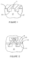
- Figure 1 is a perspective view of a section of a substrate of the present invention cut perpendicular to grooves in the substrate surface.
- Figure 2 is an oblique view of a section of the substrate of Figure 1.
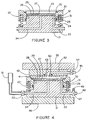
- Figure 3 is a cross-sectional view of a portion of an apparatus shown in Figure 4.
- Figure 4 is a cross-sectional view of an apparatus which may be used to carry out a method according to the present invention.
-
- The present invention provides a method for bonding a porous medium to a surface of a substrate to form a composite structure. More particularly, the present invention is directed to a method of integrally securing a porous filter medium to the surface of a substrate.
- The substrate may be any member having sufficient structural integrity to support the porous medium. The substrate, which provides support for and defines the configuration of the porous medium, may be flexible, semi-flexible or rigid. Further, the substrate includes a material which at least slightly dissolves in and is solvated by (i.e. absorbs and is softened by) the bonding composition. For example, the substrate preferably includes a polymeric material, such as a polyethersulfone, a polysulfone or a polyamide.
- The substrate may be a solid structure. If the purpose of the composite structure is to act as a filter, the substrate includes a mechanism for draining fluid away from the substrate surface. The drainage mechanism may include a plurality of channels, passages, or interconnecting pores in the substrate surface. In the illustrated embodiment, the drainage mechanism includes at least one groove and preferably a plurality of grooves, which may be interconnected, in the substrate surface. Typically, the grooves are in fluid communication with a filtrate outlet port, which may be coupled to a receiver for filtrate passing through the porous medium.
- The porous medium is preferably a porous structure that may be employed as a filter medium. The porous medium is preferably formed from a polymeric resin but may include any material capable of forming a porous structure. The porous medium may comprise any one of a number of materials, including fibrous media made by a variety of means including melt blowing, Fourdrinier deposition, or air laying. The porous medium may also comprise porous membrane media made by a variety of means including (i) introducing a solution of a resin in a relatively good solvent into a solution which is a relatively poor solvent for the resin, e.g., as described in U.S. Patent 4,340,479, (ii) by preparing a solution of a resin in a mixture of two solvents, one of which is a better solvent with a relatively higher vapor pressure compared with the second solvent, and allowing the solvents to evaporate, thereby forming a porous film, or (iii) as in the case of Teflon membranes, by precipitating a suspension of finely particulate PTFE, which is then hot compressed to form a sheet in which the particles are bonded to each other, followed by stretching the sheet to form the membrane. In a preferred embodiment, the porous medium may comprise a microporous filter medium, such as a microporous fibrous matrix or a microporous membrane. The method of this invention is particularly useful for securing a microporous filter medium to a substrate.
- Exemplary porous media may include a fluoropolymer, a polyamide, a polyethersulfone, an acrylic, a polyester, or a cellulose ester. Preferably, the porous medium includes poly(vinylidene difluoride), polytetrafluoroethylene or a nylon, such as nylon-46, nylon-6, nylon-66 or nylon-610. For example, microporous filter media may be prepared using polyamides following the procedure of U.S. Patent 4,340,479, using poly(vinylidene difluoride) following the procedure of U.S. Patents 4,341,615 and 4,774,132, using polytetrafluoroethylene following the procedure of U.S. Patents 3,953,566 and 4,096,227, using a polyethersulfone following the procedure of U.S. Patent 5,480,554.
- As shown in Figure 1, the portion of the
substrate 10 betweenadjacent grooves 12 is referred to hereinafter as thecrest 11. Thegrooves 12 may have any suitable configuration, such as a semicircular configuration, a V-shaped configuration or the generally U-shaped configuration shown in Figure 1. Similarly, thecrests 11 may have a variety of configurations, such as the apex of the angle between closely-spaced V-shaped grooves or, more preferably, a flat planar surface between more widely spaced grooves. Thecrests 11 constitute much of the substrate surface to which theporous medium 13 is secured. As shown in Figure 2, the present method integrally secures themembrane 13 to the substrate surface by forming a bond 14 between thecrests 11 and theporous medium 13. Preferably, the depth of penetration of the bond 14 is a very small fraction of the thickness of theporous medium 13, as this permits the portion of the porous medium above thecrests 11 to function effectively by allowing edgewise flow. This is particularly true of the most common type of filtration, during which all or most of the collected contaminant is caught on or very near to the exposedsurface 15 of the porous medium 13 (i.e., the surface of the porous medium which is not bonded to the substrate surface). The purified filtrate then flows edgewise through theporous filter medium 13, as shown in Figure 2. - One embodiment of the present invention comprises a method for bonding a porous medium to a substrate which includes positioning a porous medium near a surface of a substrate, preferably contacting a porous medium with a surface of a substrate, more preferably when both the porous medium and the substrate surface are dry. The dry porous medium is then impregnated with a bonding composition, which at least slightly dissolves the substrate surface without dissolving the porous medium.
- The impregnated porous medium is maintained near the substrate surface preferably in contact with the substrate surface until the substrate surface is at least slightly solvated by or slightly dissolved in the bonding composition. Preferably, the characteristics of the bonding composition are selected or adjusted to obtain a satisfactory degree of adhesion during a hold period of at least about 15 to 25 seconds. ("Hold period" refers to the time during which the impregnated
medium 29 is maintained near or in contact with thesubstrate 41 prior to flushing.) Shorter hold periods may be used but may lead to difficulties in reproducibility. Still longer hold periods, such as from about 100 to about 150 seconds, are more preferred to further aid reproducibility. Even longer hold periods may also be used. - The volume of liquid bonding composition contained within the porous medium is the apparent volume of the porous medium (i.e. its area multiplied by its thickness) multiplied by the fraction of its volume which constitutes the pores. Denoting this volume as V, in a preferred embodiment of this invention, the method is carried out in an apparatus which is designed to contain adjacent to the porous medium a volume of the bonding composition that is at least equal to the volume V and, more preferably, a volume of about one to thirty times the volume V. This volume of bonding composition is preferably contained within the voids volume of a porous element. The porous element may comprise a porous pad, which is in contact with the porous medium. The porous pad may include a compressible, porous material, which is inert to the bonding composition. The compressible, porous material may, for example, comprise one or more layers of a melt blown fibrous web. In a still more preferred version of the apparatus, a further portion of the excess bonding composition is contained within a highly liquid permeable structure in physical contact with the pad, the structure being such as to allow rapid flow of the contained bonding composition through the pad and the porous medium with low pressure drop; the highly liquid permeable structure may for example comprise one or more layers of metal and/or plastic woven mesh.
- In another embodiment of the invention, the highly liquid permeable structure is placed upon a source of the bonding composition, the compressible pad is placed on the highly liquid permeable structure, the porous medium in a dry condition is then placed on the compressible pad, the substrate is placed with its grooved face in contact with the porous medium, and the resulting assembly is contained within a closed container. The bonding composition is then introduced into the highly liquid permeable structure, thereby saturating the compressible pad and the porous medium, which in turn wets the contacted face of the substrate.
- In a more preferred embodiment, pressure is applied to force the highly liquid permeable structure, the pad, the porous medium, and the substrate together, thereby compressing the pad and assuring that the porous medium is in firm contact with the substrate.
- In a still more preferred embodiment, as soon as the desired hold period between the porous medium and the substrate has been reached, the bonding composition contained in the highly liquid permeable structure and in the pad is rapidly flushed through the porous medium, preferably in the direction of the substrate and out of the apparatus via the grooves of the substrate, either by applying air or other gas pressure to the highly liquid permeable structure, or by applying vacuum to the side of the porous medium in contact with the substrate, e.g., by applying vacuum to the substrate outlet port. The application of pressure or vacuum may then be continued until the now bonded structure is dry (i.e., residual bonding composition has been evaporated), in the one case by evaporation into the introduced air, in the other by evaporation of the solvent. Alternatively, the residual bonding composition may be evaporated by applying a vacuum to the substrate and the porous medium.
- The rapid flushing of bonding composition through the porous medium towards the substrate is beneficial, as it removes bonding composition containing dissolved substrate from the portion of the porous medium not in contact with the substrate. Allowing dissolved substrate to remain in place could partially obstruct flow in the this portion of the porous medium.
- An apparatus for carrying out a preferred embodiment of the present invention is shown schematically in Figures 3 and 4. Figure 3 represents a portion of the apparatus which is shown more completely in Figure 4. In Figure 3, a
base 21 cooperates with anupper member 22 to form a sealable chamber orcavity 23. Theupper member 22 is located vertically bysprings 24, which are shown in their fully extended position. A first elastomeric O-ring 25 provides a sliding seal between the base 21 and theupper member 22, and a second elastomeric O-ring 26 is configured to provide a seal to the outer rim of the grooved substrate 41 (as shown in Figure 4). - In a preferred mode of operation, a highly liquid
permeable structure 27, of which a preferred form is a woven wire or plastic mesh, is placed in thecavity 23, followed by acompressible pad 28, and then in turn by theporous medium 29. An upper portion of theinner periphery 30 of theupper member 22 is shaped to accept the outer contour of thesubstrate 41 and a lower portion of theinner periphery 30 is shaped to accept the outer contour of theporous medium 29, assuring accurate register between the grooves of thesubstrate 41 and theporous medium 29. For example, theinner periphery 30 of theupper member 22 may be contoured to a D-shaped substrate and a smaller D-shaped porous medium. Agrooved section 31 extends 360° around the portion of thebase 21 above the first O-ring 25. Thegroove 31 is connected to anannular passage 32 which communicates with the highly liquidpermeable structure 27 and which may generally be about 0.076 mm (.003") to 0.152 mm (.006") in width and about 5.1-12.7 mm (0.2-0.5") long extending 360° around thebase 21. Thegroove 31 is connected also to aflow passage 33. Asecond flow passage 34 connects the center of the upper face of the base 21 to a port located on the outer face of thebase 21. - Figure 4 represents an exemplary assembled apparatus ready for use to accomplish the bonding of a porous medium 29 to a
grooved substrate 41. In Figure 4, thesubstrate 41 is placed with its grooved face down onto theupper member 22. Anadaptor 42 together with aseal 43 are placed on thesubstrate 41. Theadaptor 42 contains apassageway 52 connecting theoutlet port 60 of thesubstrate 41 to avalve 44. Theoutlet 45 of thevalve 44 is connected to a source of vacuum, such as a vacuum pump. Thebase 21 and theadapter 42 have been placed between thelower platen 46 and theupper platen 55 of a press. Sufficient force is applied by the press to compresssprings 24 and thereby to bring the porous medium 29 into close contact with the grooved face of thesubstrate 41. Preferably, the pressure is further increased to apply a force in the range of about 69 kPa to 345 kPa (10 to 50 pounds per square inch) of area of thesubstrate 41, in the process reducing the thickness of thecompressible pad 28 to about 50 to 80% of its starting thickness. A threeway valve 47 is connected to theflow passageway 33. Afirst port 48 of thevalve 47 is connected to a reservoir containing the liquid bonding composition, which is maintained at a pressure of about 103 kPa to 345 kPa (15 to 50 pounds per square inch). Asecond port 49 of thevalve 47 is connected to a source of vacuum, such as a vacuum pump. Avalve 50 is connected to theflow passageway 34, between the base 21 and an open-topped transparent-walled vessel 51. The mid point of thevessel 51 is preferably located vertically about 12.7 cm to 25.4 cm (5 to 10 inches) above the level of theporous medium 29. - In a preferred embodiment of the present invention, the apparatus shown in Figures 3 and 4 is operated in a four stage procedure described in sections A to D below.
- A
valve 47 is opened to thefirst port 48, allowing the liquid bonding composition to pass through thepassageway 33 to thegroove 31, which it fills within about one second. The liquid bonding composition then flows in a nearly uniform stream through the full 360° of theannular passage 32 into the outer periphery of highly liquidpermeable member 27, thence through thepad 28, where it is rapidly absorbed by theporous medium 29, which then wets the surfaces of thesubstrate 41 that are in contact with theporous medium 29. An excess of the fluid bonding composition is allowed to pass through thepassageway 34 and thevalve 50 into thevessel 51 until thevessel 51 is filled to a level about 12.7 cm to 25.4 cm (5 to 10 inches) above theporous medium 29, at which time thevalve 47 is closed. If the vapor pressure of the bonding composition is above about 1.33 kPa (10mm of mercury), the net effect of the increase in pressure, induced due to the vapor pressure of the bonding composition and the 12.7 cm to 25.4 cm (5" to 10") liquid head invessel 51, is to increase the amount of gas confined within thepassageway 52 of theadapter 42 and in the grooves of thesubstrate 41. This increase in the amount of confined gas typically prevents the liquid bonding composition from penetrating into the grooves of thesubstrate 41. The penetration into the grooves to a small portion of their depth may, however, be acceptable in practice. - The filling step is preferably done as quickly as possible, for example, in no more than about 15 seconds and, more preferably, in no more than about 5 seconds, from the opening of the
valve 47 to the time the liquid bonding composition in thevessel 51 reaches the desired level. - It should be noted that the transparent-
walled vessel 51 serves a dual function; first, the vessel maintains a differential pressure of a few inches (1 inch = 2.54 cm) of liquid volume; and second, the vessel acts as a reservoir from which bonding composition may be drawn to thoroughly impregnate the porous medium 29 in contact with thesubstrate 41. - The time during which the impregnated
porous medium 29 is maintained in contact with thesubstrate 41 prior to flushing (herein the "hold period") is an important aspect of the process. During the hold period the bonding composition diffuses into thesubstrate 41, causing the outer surface of thesubstrate 41 in contact with the impregnated porous medium to soften and become tacky. In essence, this outer surface of thesubstrate 41 may be converted into an adhesive, bonding layer. - At the same time, some of the
substrate 41 dissolves in the bonding composition. At least a portion of this dissolved substrate diffuses through the bonding composition within theporous medium 29. - The optimum duration of the hold period is determined empirically for a specific bonding composition. For example, the final composite structure may be tested by passing water therethrough in the normal flow direction (i.e., from the porous material to the substrate) in order to determine what percentage of the permeability of the
porous medium 29 has been lost. This percentage becomes higher as the hold period is increased. The composite structure may also be tested by flowing water in the reverse direction, in order to determine the pressure at which theporous medium 29 separates from thesubstrate 41. Several specimens can be made using a given bonding composition and various hold periods. The test data derived from these specimens may then be used to select an optimum hold period. - The optimum hold period varies greatly depending on the particular chemical species used to prepare the bonding composition. The bonding composition may be compounded using a combination of an aggressive chemical species, i.e., a chemical species which is a good solvent for the substrate (first chemical species), with a chemical species which is a non-solvent for the substrate (second chemical species). The degree of solvency of the substrate in the bonding composition, and hence the hold period required, may be adjusted by varying the proportions of the two components. Using such a combination is a preferred feature of the present invention.
- During the filling operation, some parts of the
porous medium 29 and thesubstrate 41 are unavoidably wetted by the bonding composition before other parts. For example, if the substrate and porous medium being bonded are quite large, some parts may be exposed for as much as 15 seconds or more longer than other parts. If the bonding composition is selected or compounded such that the hold period is about 15 seconds, then some parts of the porous medium 29 in contact with thesubstrate 41 may have been exposed for twice as long as others. This may lead to overbonding of one section of the resulting composite structure with flow of liquid through the filter in service inhibited locally, while another section may fail in the reverse pressure mode. - The bonding composition may comprise a mixture of chemical species which makes possible relatively longer hold periods. As noted above, the advantage of longer hold periods is that the effect of the differential wetting which can occur during the filling operation is minimized. When compared, for example, with the same 15 second wetting differential of the example of the preceding paragraph, the use of a mixture of chemical species composition for which bonding is optimized by a 150 second hold period reduces the difference between the longest and shortest total time during which any part of the substrate is in contact with the impregnated porous medium prior to flushing to about 10% of the hold period.
- Prior to drying, the bulk of the dissolved substrate which has diffused into the bonding composition within the porous medium 29 during the preceding step is removed.
- In step C of this procedure, the undesired dissolved substrate within the porous medium 29 at the termination of the hold period is removed by closing the
valve 50 between thevessel 51 and thebase 21 and opening thevalve 44 at theadapter 42 to avacuum source 45 for about 1 to 5 seconds. This flushes the liquid bonding composition contained in the twolayers substrate 41 and away from the surface of thesubstrate 41 through the grooves or pores in thesubstrate 41 and along thepassage 52 in theadapter 42. Flushing with this controlled quantity of the bonding composition is sufficient to remove the dissolved substrate fromporous medium 29, while having a negligible effect on the viscous material which has formed a bond between thesubstrate 41 and theporous medium 29. - In the fourth stage D, the bonding composition is removed by evaporation. As in stage A, it is desirable to reduce as much as possible differences in exposure time in this stage between one part of the bonded surface and another. In one embodiment of the present invention, this may be accomplished in part by applying a high degree of vacuum at the conclusion of the hold period, thereby rapidly removing the bonding composition by evaporation as the bonding composition is being flushed through the porous medium. The effectiveness of this procedure is, however, hampered by the absorption of heat during vaporization which cools the chemical species contained in the bonding composition, reducing their vapor pressure and the effective pumping rate.
- Preferably, the bonding composition is a mixture of at least two chemical species, the first chemical species being a good solvent for the substrate and the second chemical species being a non-solvent for the
substrate 41. The non-solvent species typically has a lower vapor pressure than the solvent species, preferably by about 10% or more at ambient temperature. Preferably, neither the solvent species nor the non-solvent species is a solvent for the porous medium. When vacuum is applied to theclosed chamber 23 in step D, the solvent species is removed faster than the non-solvent species, thereby decreasing the concentration of the solvent species in the residual bonding composition in theclosed chamber 23. Preferably, the starting constitution of the bonding composition is chosen such that the residual bonding composition becomes a non-solvent for thesubstrate 41 after a very short period of evaporation, thereby preventing any further dissolution of thesubstrate 41 and limiting the time during which dissolution of the substrate occurs to a very short period, which may be as short as about 5 seconds or less. - Exemplary chemical species which may be used as the solvent species include but are not limited to halogenated hydrocarbons, such as methylene chloride or chloroform. Preferably, the solvent species includes methylene chloride. Exemplary chemical species which may be used as the non-solvent species include but are not limited to alcohols and hydrocarbons. Preferably, the non-solvent species includes methanol, cyclopentane or polymethyl pentene. Exemplary bonding compositions for bonding a polyamide, a poly(vinylidene fluoride) or a polytetrafluoroethylene membrane to a polyethersulfone substrate include mixtures of methylene chloride as the solvent species and methyl alcohol as the non-solvent species or methylene chloride and polymethyl pentene as the non-solvent species.
Claims (15)
- A method for bonding a porous medium to a surface of a substrate using a bonding composition, the surface of the substrate being at least slightly dissolvable in the bonding composition, the method characterized by:applying pressure to compress the porous medium and the substrate;introducing a bonding composition which at least slightly dissolves the surface of the substrate without dissolving the porous medium;allowing at least a portion of the bonding composition containing dissolved substrate to flow into the porous medium; andapplying a vacuum to remove the bonding composition and to resolidify the dissolved substrate in the pores of the porous medium, thereby bonding the porous medium and the surface of the substrate to form a composite filter structure.
- The method of claim 1 wherein applying pressure includes pressing the porous medium and the substrate together in a press.
- The method of claim 1 or 2 wherein applying pressure includes applying a force in the range from about 69kPa to 345kPa over the area of the substrate.
- The method of any one of the preceding claims wherein applying pressure includes pressing the porous medium and the substrate together by a compressible structure.
- The method according to any one of the preceding claims wherein applying pressure includes pressing the porous medium in contact with the substrate.
- The method of any one of the preceding claims wherein applying pressure includes pressing the porous medium against a grooved surface of the substrate.
- The method of any one of the preceding claims wherein applying a vacuum includes evaporating the bonding composition from the porous medium and the substrate.
- The method of any one of the preceding claims wherein applying a vacuum includes applying a high degree of vacuum to rapidly remove bonding composition by evaporation from the porous medium.
- The method of any one of the preceding claims further comprising positioning a dry porous medium to be in contact with or near the surface of the substrate prior to introducing the bonding composition.
- The method of any one of the preceding claims wherein the porous medium comprises a filter medium.
- The method of claim 10 wherein the filter medium comprises a microporous filter medium.
- The method of any one of the preceding claims wherein the porous medium comprises a polymeric material.
- The method of any one of the preceding claims wherein the substrate comprises a polymeric material.
- The method of any one of the preceding claims wherein the substrate comprises a solid structure having a drainage mechanism in the surface of the substrate.
- The method of any one of the preceding claims wherein the bonded porous medium retains porosity.
Applications Claiming Priority (3)
| Application Number | Priority Date | Filing Date | Title |
|---|---|---|---|
| US08/038,257 US5458719A (en) | 1993-03-24 | 1993-03-24 | Method for bonding a porous medium to a substrate |
| US38257 | 1993-03-24 | ||
| EP94910989A EP0702626B1 (en) | 1993-03-24 | 1994-03-23 | Method for bonding a porous medium to a substrate |
Related Parent Applications (1)
| Application Number | Title | Priority Date | Filing Date |
|---|---|---|---|
| EP94910989A Division EP0702626B1 (en) | 1993-03-24 | 1994-03-23 | Method for bonding a porous medium to a substrate |
Publications (1)
| Publication Number | Publication Date |
|---|---|
| EP0985518A1 true EP0985518A1 (en) | 2000-03-15 |
Family
ID=21898902
Family Applications (5)
| Application Number | Title | Priority Date | Filing Date |
|---|---|---|---|
| EP99203676A Withdrawn EP0985518A1 (en) | 1993-03-24 | 1994-03-23 | Method for bonding a porous medium to a substrate |
| EP99203675A Withdrawn EP0985517A1 (en) | 1993-03-24 | 1994-03-23 | Method for bonding a porous medium to a substrate |
| EP94910989A Expired - Lifetime EP0702626B1 (en) | 1993-03-24 | 1994-03-23 | Method for bonding a porous medium to a substrate |
| EP99203677A Withdrawn EP0985699A1 (en) | 1993-03-24 | 1994-03-23 | Method for bonding a porous medium to a substrate |
| EP94930492A Expired - Lifetime EP0730490B1 (en) | 1993-03-24 | 1994-09-28 | A composite structure and a method for forming same |
Family Applications After (4)
| Application Number | Title | Priority Date | Filing Date |
|---|---|---|---|
| EP99203675A Withdrawn EP0985517A1 (en) | 1993-03-24 | 1994-03-23 | Method for bonding a porous medium to a substrate |
| EP94910989A Expired - Lifetime EP0702626B1 (en) | 1993-03-24 | 1994-03-23 | Method for bonding a porous medium to a substrate |
| EP99203677A Withdrawn EP0985699A1 (en) | 1993-03-24 | 1994-03-23 | Method for bonding a porous medium to a substrate |
| EP94930492A Expired - Lifetime EP0730490B1 (en) | 1993-03-24 | 1994-09-28 | A composite structure and a method for forming same |
Country Status (8)
| Country | Link |
|---|---|
| US (3) | US5458719A (en) |
| EP (5) | EP0985518A1 (en) |
| JP (2) | JPH08508215A (en) |
| AU (1) | AU7959594A (en) |
| CA (1) | CA2158943A1 (en) |
| DE (2) | DE69425325T2 (en) |
| DK (1) | DK0730490T5 (en) |
| WO (2) | WO1994021462A1 (en) |
Cited By (1)
| Publication number | Priority date | Publication date | Assignee | Title |
|---|---|---|---|---|
| CN105016456A (en) * | 2015-08-12 | 2015-11-04 | 上海世浦泰膜科技有限公司 | Filter element with self-adhesion filter membranes and manufacturing method thereof |
Families Citing this family (59)
| Publication number | Priority date | Publication date | Assignee | Title |
|---|---|---|---|---|
| US5458719A (en) * | 1993-03-24 | 1995-10-17 | Pall Corporation | Method for bonding a porous medium to a substrate |
| CA2160282A1 (en) * | 1995-02-14 | 1996-08-15 | Michael R. Gildersleeve | Supported membrane assembly |
| US5660380A (en) * | 1995-08-15 | 1997-08-26 | W. L. Gore & Associates, Inc. | Vacuum fixture and method for dimensioning and manipulating materials |
| US6508974B1 (en) | 1996-02-15 | 2003-01-21 | David Loving | Process for fiberglass molding using a vacuum |
| US6203749B1 (en) * | 1996-02-15 | 2001-03-20 | David Loving | Process for fiberglass molding using a vacuum |
| JP3430783B2 (en) * | 1996-04-11 | 2003-07-28 | 東レ株式会社 | Liquid separation element, apparatus and processing method |
| TW438679B (en) * | 1996-08-09 | 2001-06-07 | Daikin Ind Ltd | Filter medium and air filter unit using the same |
| US6113827A (en) | 1996-11-05 | 2000-09-05 | Styczynski; Robert J. | Method for molding and curing silicone |
| US6017484A (en) * | 1997-01-21 | 2000-01-25 | Harold P. Hale | Method for manufacture of minimum porosity, wrinkle free composite parts |
| US5976380A (en) * | 1997-05-01 | 1999-11-02 | Millipore Corporation | Article of manufacture including a surface modified membrane and process |
| US6354444B1 (en) * | 1997-07-01 | 2002-03-12 | Zenon Environmental Inc. | Hollow fiber membrane and braided tubular support therefor |
| US6514412B1 (en) * | 1998-06-18 | 2003-02-04 | 3M Innovative Properties Company | Microstructured separation device |
| US6420622B1 (en) | 1997-08-01 | 2002-07-16 | 3M Innovative Properties Company | Medical article having fluid control film |
| US6524488B1 (en) | 1998-06-18 | 2003-02-25 | 3M Innovative Properties Company | Method of filtering certain particles from a fluid using a depth loading filtration media |
| US6110259A (en) * | 1997-11-21 | 2000-08-29 | Jlj International, Inc. | Smoke evacuation system |
| US6669905B1 (en) * | 1998-05-21 | 2003-12-30 | Baxter International Inc. | Systems and methods for collecting plasma that is free or virtually free of cellular blood species |
| EP1028176A1 (en) * | 1999-02-12 | 2000-08-16 | Balzers Hochvakuum AG | Substrate holder and method for its use |
| US6524675B1 (en) | 1999-05-13 | 2003-02-25 | 3M Innovative Properties Company | Adhesive-back articles |
| US7223364B1 (en) | 1999-07-07 | 2007-05-29 | 3M Innovative Properties Company | Detection article having fluid control film |
| AU6115000A (en) | 1999-07-21 | 2001-02-13 | Procter & Gamble Company, The | Microorganism filter and method for removing microorganism from water |
| US20010050250A1 (en) * | 1999-09-14 | 2001-12-13 | Olli Hognabba | Corrosion-resistant filter element |
| US6454839B1 (en) | 1999-10-19 | 2002-09-24 | 3M Innovative Properties Company | Electrofiltration apparatus |
| EP1251935A1 (en) | 2000-01-14 | 2002-10-30 | Pall Corporation | Filter for gas analysis |
| US6617151B1 (en) | 2000-02-29 | 2003-09-09 | Gore Enterprise Holdings, Inc. | Method of closing a cell containment device with a wet seal |
| JP4786122B2 (en) * | 2000-12-22 | 2011-10-05 | ジーイー・オズモニクス・インコーポレイテッド | Cross flow filter media and cartridge |
| GB0107100D0 (en) * | 2001-03-21 | 2001-05-09 | Thames Water Products Ltd | Apparatus for filtering a liquid |
| US7615152B2 (en) | 2001-08-23 | 2009-11-10 | Pur Water Purification Products, Inc. | Water filter device |
| US7614507B2 (en) | 2001-08-23 | 2009-11-10 | Pur Water Purification Products Inc. | Water filter materials, water filters and kits containing particles coated with cationic polymer and processes for using the same |
| KR100777951B1 (en) | 2001-08-23 | 2007-11-28 | 더 프록터 앤드 갬블 캄파니 | Water filter materials, corresponding water filters and processes for using the same |
| US20050279696A1 (en) | 2001-08-23 | 2005-12-22 | Bahm Jeannine R | Water filter materials and water filters containing a mixture of microporous and mesoporous carbon particles |
| US7614508B2 (en) | 2001-08-23 | 2009-11-10 | Pur Water Purification Products Inc. | Water filter materials, water filters and kits containing silver coated particles and processes for using the same |
| US6654201B2 (en) * | 2001-12-07 | 2003-11-25 | Hitachi Global Storage Technologies Netherlands B.V. | Shroud for disk drive with particulate filter elements |
| US7051883B2 (en) * | 2003-07-07 | 2006-05-30 | Reemay, Inc. | Wetlaid-spunbond laminate membrane support |
| US7534348B2 (en) * | 2003-09-12 | 2009-05-19 | Fenwal, Inc. | Flow-through removal device and system using such device |
| US7087135B2 (en) * | 2003-11-14 | 2006-08-08 | Bio Med Sciences, Inc. | Process for the manufacture of interpenetrating polymer network sheeting and useful articles thereof |
| US7424821B1 (en) * | 2004-06-25 | 2008-09-16 | Baxter International Inc. | Characterization of porous media |
| US7686907B1 (en) | 2005-02-01 | 2010-03-30 | Brigham Young University | Phase-changing sacrificial materials for manufacture of high-performance polymeric capillary microchips |
| DE202005004151U1 (en) * | 2005-03-15 | 2006-07-27 | Keller Lufttechnik Gmbh + Co. Kg | Demister filter to remove lubricant or coolant droplets from air has polymer mesh incorporating ionization wires |
| US7441667B2 (en) * | 2005-12-15 | 2008-10-28 | E.I. Du Pont De Nemours And Company | Composite membranes for liquid filtration having improved uniformity and adhesion of substrate to membrane |
| US8109314B1 (en) * | 2007-06-07 | 2012-02-07 | Santiago Rodriguez | Air clamp |
| DE102008019085A1 (en) | 2008-04-15 | 2009-10-22 | Microdyn - Nadir Gmbh | Filter composite material, process for its preparation and flat filter elements made of the filter composite material |
| FR2931081B1 (en) * | 2008-05-14 | 2010-06-25 | Direction Et Pirorites | DEVICE FOR FILTRATION OF A COMPLEX LIQUID SUCH AS BLOOD, IN PARTICULAR APPLICABLE TO AN AUTOSFUSER |
| US7927731B2 (en) * | 2008-07-01 | 2011-04-19 | Deeya Energy, Inc. | Redox flow cell |
| WO2010042900A1 (en) * | 2008-10-10 | 2010-04-15 | Deeya Energy Technologies, Inc. | Methods for bonding porous flexible membranes using solvent |
| CN102068924B (en) * | 2010-12-22 | 2013-12-18 | 中国科学院长春应用化学研究所 | Polytetrafluoroethylene composite membrane and preparation method thereof |
| US9393766B2 (en) | 2011-05-09 | 2016-07-19 | Boehringer Ingelheim Microparts Gmbh | Process for joining a foil or a membrane |
| EP2730331B1 (en) * | 2011-07-07 | 2021-01-20 | Toray Industries, Inc. | Separation membrane element |
| CN103842055B (en) * | 2011-09-29 | 2016-08-17 | 东丽株式会社 | Separate film, separating film element and separate the manufacture method of film |
| JP6136269B2 (en) * | 2011-09-29 | 2017-05-31 | 東レ株式会社 | Separation membrane element for water treatment |
| CN104097323B (en) * | 2013-04-02 | 2016-09-14 | 凯硕电脑(苏州)有限公司 | Press fit device |
| JP5860431B2 (en) * | 2013-04-25 | 2016-02-16 | 東京エレクトロン株式会社 | Joining apparatus, joining system, and joining method |
| DE102013113155A1 (en) * | 2013-11-28 | 2015-05-28 | Emitec France S.A.S | Liquid cleaning element for cleaning a liquid |
| DE102014103715A1 (en) | 2014-03-19 | 2015-09-24 | Emitec France S.A.S | Liquid cleaning element for cleaning a liquid |
| US10376627B2 (en) | 2014-03-24 | 2019-08-13 | Fenwal, Inc. | Flexible biological fluid filters |
| US10159778B2 (en) | 2014-03-24 | 2018-12-25 | Fenwal, Inc. | Biological fluid filters having flexible walls and methods for making such filters |
| US9968738B2 (en) | 2014-03-24 | 2018-05-15 | Fenwal, Inc. | Biological fluid filters with molded frame and methods for making such filters |
| US9782707B2 (en) | 2014-03-24 | 2017-10-10 | Fenwal, Inc. | Biological fluid filters having flexible walls and methods for making such filters |
| US9796166B2 (en) | 2014-03-24 | 2017-10-24 | Fenwal, Inc. | Flexible biological fluid filters |
| CN108854854B (en) * | 2017-05-16 | 2021-07-20 | 厦门大学 | Functional fluid door control system |
Citations (9)
| Publication number | Priority date | Publication date | Assignee | Title |
|---|---|---|---|---|
| FR1191620A (en) * | 1958-02-17 | 1959-10-21 | Electro Mecanique Aw Soc | A method of bonding a fabric (or other similar flexible and permeable material) to a plastic backing and the product thus obtained |
| FR2469896A1 (en) * | 1979-11-21 | 1981-05-29 | Eurogalerie Sarl | Evacuated platform for assembly of polystyrene framed display panels - for convenient assembly of panel and frames by solvent welding |
| US4302270A (en) * | 1979-06-26 | 1981-11-24 | Dorr-Oliver Incorporated | Method of bonding an ultrafiltration membrane assembly |
| GB2090543A (en) * | 1979-11-05 | 1982-07-14 | Millipore Corp | A method for bonding a filter membrane to a plastics support |
| US4576715A (en) * | 1981-02-13 | 1986-03-18 | Dresser Industries, Inc | Membrane pack and method of making |
| US4595446A (en) * | 1985-04-24 | 1986-06-17 | Tape, Inc. | Solvent bonding process utilizing spray-mist |
| NL8900201A (en) * | 1989-01-27 | 1990-08-16 | Alfred Albert Felix | Bonding fibrous material to solid thermoplastic surface - by contact in presence of solvent or swelling agent for thermoplast, embedding fibres partly in thermoplast |
| EP0480199A2 (en) * | 1990-10-10 | 1992-04-15 | W.H. Brady Co. | Adhesive sheet materials for signmaking machines |
| EP0499917A1 (en) * | 1991-02-21 | 1992-08-26 | Synthes AG, Chur | High-strength, high-modulus, compound-filament or compound-film implant and method for producing it |
Family Cites Families (49)
| Publication number | Priority date | Publication date | Assignee | Title |
|---|---|---|---|---|
| BE433913A (en) * | ||||
| US2500053A (en) * | 1947-05-14 | 1950-03-07 | Alvadore M Andrews | Method of joining pieces of plastic |
| US2729573A (en) * | 1953-05-18 | 1956-01-03 | Bernard B Goldner | Plastic welding composition |
| GB1168722A (en) * | 1967-02-22 | 1969-10-29 | Atomic Energy Authority Uk | Improvements in or relating to Reverse Osmosis. |
| US3479986A (en) * | 1967-09-22 | 1969-11-25 | Gaf Corp | Apparatus for liquid solvent sealing of plastic film cartridges |
| US3544384A (en) * | 1968-05-07 | 1970-12-01 | Tudor Ab | Method of making a laminated porous battery separator |
| US3578175A (en) * | 1969-04-23 | 1971-05-11 | Universal Water Corp | Helically wound semipermeable membrane |
| US3663326A (en) * | 1970-01-09 | 1972-05-16 | Western Electric Co | Article holding methods and assemblage |
| SE392582B (en) * | 1970-05-21 | 1977-04-04 | Gore & Ass | PROCEDURE FOR THE PREPARATION OF A POROST MATERIAL, BY EXPANDING AND STRETCHING A TETRAFLUORETENE POLYMER PREPARED IN AN PASTE-FORMING EXTENSION PROCEDURE |
| US3730353A (en) * | 1970-12-28 | 1973-05-01 | Millipore Corp | Filter support and filter unit construction |
| DE2117592C3 (en) * | 1971-04-10 | 1978-05-03 | Vdo Adolf Schindling Ag, 6000 Frankfurt | Method for attaching filter fabric made of plastic |
| US3791526A (en) * | 1971-08-10 | 1974-02-12 | Westinghouse Electric Corp | Solvent weld adhesive for reverse osmosis membranes |
| US4096227A (en) * | 1973-07-03 | 1978-06-20 | W. L. Gore & Associates, Inc. | Process for producing filled porous PTFE products |
| JPS5215398B2 (en) * | 1973-11-09 | 1977-04-28 | ||
| US3928110A (en) * | 1974-03-11 | 1975-12-23 | Goodyear Tire & Rubber | Film bonding using a solvent saturated cloth wick |
| FR2285227A1 (en) * | 1974-09-20 | 1976-04-16 | Ugine Kuhlmann | PROCESS FOR ASSEMBLING VINYLIDENE POLYFLUORIDE PARTS |
| US4181549A (en) * | 1977-03-10 | 1980-01-01 | American Hospital Supply Corporation | Solvent-bonded joint and method of making the same |
| YU51378A (en) * | 1977-04-04 | 1982-10-31 | Dresser Ind | Membrane packing enabling the passing of leaking fluids |
| US4131664A (en) * | 1977-09-28 | 1978-12-26 | Allen Industries, Inc. | Method of making a multiple-density fibrous acoustical panel |
| NO153836C (en) * | 1978-05-15 | 1986-06-04 | Pall Corp | HYDROFILE, ALCOHOLUALLY SOLUBLE POLYAMIDE MEMBRANES AND PROCEDURES FOR THEIR PREPARATION. |
| US4187182A (en) * | 1978-07-21 | 1980-02-05 | Pall Corporation | Box filter |
| US4501663A (en) * | 1979-11-05 | 1985-02-26 | Millipore Corporation | Filter cartridges and methods and components for making them |
| DE3175761D1 (en) * | 1980-01-29 | 1987-02-05 | Atochem | Electrolysis diaphragm and method for its manufacture |
| US4311661A (en) * | 1980-05-05 | 1982-01-19 | Mcdonnell Douglas Corporation | Resin impregnation process |
| US4347208A (en) * | 1981-04-13 | 1982-08-31 | Amf Incorporated | Method of making filter cell having sealed periphery |
| JPS60139302A (en) * | 1983-12-28 | 1985-07-24 | Teijin Ltd | Preparation of membrane constituent body |
| JPS61143118A (en) * | 1984-12-18 | 1986-06-30 | Mitsui Petrochem Ind Ltd | Method for joining molded item of poly 4-methyl-1-pentene |
| US4666549A (en) * | 1985-08-29 | 1987-05-19 | Phillips Petroleum Company | Polymer welding process and composition |
| US4786351A (en) * | 1985-12-31 | 1988-11-22 | Astechnologies, Inc. | Process and apparatus for simultaneously shaping foam and laminating fabric thereto |
| US4774132A (en) * | 1986-05-01 | 1988-09-27 | Pall Corporation | Polyvinylidene difluoride structure |
| US5108691A (en) * | 1986-09-03 | 1992-04-28 | Astechnologies, Inc. | Compressing and shaping thermoformable mats using superheated steam |
| JPS6372305A (en) * | 1986-09-17 | 1988-04-02 | Fuji Photo Film Co Ltd | Bonding method for filter membrane of filter cartridge |
| JPS63240918A (en) * | 1987-03-27 | 1988-10-06 | Asahi Glass Co Ltd | Gas separating membrane |
| US4842739A (en) * | 1987-08-20 | 1989-06-27 | Minnesota Mining And Manufacturing Company | High surface area filter cartridge |
| US4802982A (en) * | 1987-10-01 | 1989-02-07 | Desalination Systems, Inc. | Spiral-wound membrane with improved permeate carrier |
| DE3803341A1 (en) * | 1988-02-04 | 1989-08-10 | Sartorius Gmbh | FLUID-OPEN-ENDING SITES HAVING POROESE MEMBRANE FILTERS AND THEIR USE |
| US4863792A (en) * | 1988-10-14 | 1989-09-05 | Minnesota Mining And Manufacturing Company | Multi-layer laminates of microporous films |
| US4942013A (en) * | 1989-03-27 | 1990-07-17 | Mcdonnell Douglas Corporation | Vacuum resin impregnation process |
| US4906372A (en) * | 1989-05-17 | 1990-03-06 | Desalination Systems, Inc. | Spiral-wound membrane cartridge |
| US4937024A (en) * | 1989-06-26 | 1990-06-26 | Borden, Inc. | Method for bonding lignocellulosic material with gaseous esters |
| US5259894A (en) * | 1990-01-26 | 1993-11-09 | Sampson Richard K | Method for solvent bonding non-porous materials to automatically create variable bond characteristics |
| US5017292A (en) * | 1990-05-10 | 1991-05-21 | Millipore Corporation | Membrane, process and system for isolating virus from solution |
| US5110682A (en) * | 1990-08-20 | 1992-05-05 | Phillips Petroleum Company | Bonding of composites |
| US5275725A (en) * | 1990-11-30 | 1994-01-04 | Daicel Chemical Industries, Ltd. | Flat separation membrane leaf and rotary separation apparatus containing flat membranes |
| WO1992009358A1 (en) * | 1990-11-30 | 1992-06-11 | Daicel Chemical Industries, Ltd. | Flat sheet type separating film leaf |
| US5143616A (en) * | 1991-05-15 | 1992-09-01 | Pall Corporation | Composite structure and method of making |
| US5273694A (en) * | 1992-08-28 | 1993-12-28 | E. I. Du Pont De Nemours And Company | Process for making ion exchange membranes and films |
| US5458719A (en) * | 1993-03-24 | 1995-10-17 | Pall Corporation | Method for bonding a porous medium to a substrate |
| TW267949B (en) * | 1993-05-25 | 1996-01-11 | Kubota Kk | Process of producing filtration membrane element |
-
1993
- 1993-03-24 US US08/038,257 patent/US5458719A/en not_active Expired - Fee Related
-
1994
- 1994-03-23 EP EP99203676A patent/EP0985518A1/en not_active Withdrawn
- 1994-03-23 WO PCT/US1994/003104 patent/WO1994021462A1/en active IP Right Grant
- 1994-03-23 CA CA002158943A patent/CA2158943A1/en not_active Abandoned
- 1994-03-23 EP EP99203675A patent/EP0985517A1/en not_active Withdrawn
- 1994-03-23 EP EP94910989A patent/EP0702626B1/en not_active Expired - Lifetime
- 1994-03-23 EP EP99203677A patent/EP0985699A1/en not_active Withdrawn
- 1994-03-23 JP JP6521333A patent/JPH08508215A/en not_active Ceased
- 1994-03-23 DE DE69425325T patent/DE69425325T2/en not_active Expired - Fee Related
- 1994-09-28 EP EP94930492A patent/EP0730490B1/en not_active Expired - Lifetime
- 1994-09-28 DK DK94930492T patent/DK0730490T5/en active
- 1994-09-28 JP JP8511687A patent/JP2955367B2/en not_active Expired - Fee Related
- 1994-09-28 US US08/649,593 patent/US5804280A/en not_active Expired - Fee Related
- 1994-09-28 DE DE69425672T patent/DE69425672T2/en not_active Expired - Fee Related
- 1994-09-28 AU AU79595/94A patent/AU7959594A/en not_active Abandoned
- 1994-09-28 WO PCT/US1994/010942 patent/WO1996009879A1/en active IP Right Grant
-
1997
- 1997-06-16 US US08/874,438 patent/US5919330A/en not_active Expired - Fee Related
Patent Citations (9)
| Publication number | Priority date | Publication date | Assignee | Title |
|---|---|---|---|---|
| FR1191620A (en) * | 1958-02-17 | 1959-10-21 | Electro Mecanique Aw Soc | A method of bonding a fabric (or other similar flexible and permeable material) to a plastic backing and the product thus obtained |
| US4302270A (en) * | 1979-06-26 | 1981-11-24 | Dorr-Oliver Incorporated | Method of bonding an ultrafiltration membrane assembly |
| GB2090543A (en) * | 1979-11-05 | 1982-07-14 | Millipore Corp | A method for bonding a filter membrane to a plastics support |
| FR2469896A1 (en) * | 1979-11-21 | 1981-05-29 | Eurogalerie Sarl | Evacuated platform for assembly of polystyrene framed display panels - for convenient assembly of panel and frames by solvent welding |
| US4576715A (en) * | 1981-02-13 | 1986-03-18 | Dresser Industries, Inc | Membrane pack and method of making |
| US4595446A (en) * | 1985-04-24 | 1986-06-17 | Tape, Inc. | Solvent bonding process utilizing spray-mist |
| NL8900201A (en) * | 1989-01-27 | 1990-08-16 | Alfred Albert Felix | Bonding fibrous material to solid thermoplastic surface - by contact in presence of solvent or swelling agent for thermoplast, embedding fibres partly in thermoplast |
| EP0480199A2 (en) * | 1990-10-10 | 1992-04-15 | W.H. Brady Co. | Adhesive sheet materials for signmaking machines |
| EP0499917A1 (en) * | 1991-02-21 | 1992-08-26 | Synthes AG, Chur | High-strength, high-modulus, compound-filament or compound-film implant and method for producing it |
Cited By (1)
| Publication number | Priority date | Publication date | Assignee | Title |
|---|---|---|---|---|
| CN105016456A (en) * | 2015-08-12 | 2015-11-04 | 上海世浦泰膜科技有限公司 | Filter element with self-adhesion filter membranes and manufacturing method thereof |
Also Published As
| Publication number | Publication date |
|---|---|
| WO1996009879A1 (en) | 1996-04-04 |
| DK0730490T5 (en) | 2001-01-22 |
| AU7959594A (en) | 1996-04-19 |
| EP0702626A1 (en) | 1996-03-27 |
| EP0702626B1 (en) | 2000-07-19 |
| EP0985699A1 (en) | 2000-03-15 |
| US5458719A (en) | 1995-10-17 |
| DE69425672T2 (en) | 2001-04-19 |
| EP0730490A1 (en) | 1996-09-11 |
| US5804280A (en) | 1998-09-08 |
| WO1994021462A1 (en) | 1994-09-29 |
| CA2158943A1 (en) | 1994-09-29 |
| DE69425325D1 (en) | 2000-08-24 |
| DK0730490T3 (en) | 2000-10-16 |
| JPH09505774A (en) | 1997-06-10 |
| DE69425672D1 (en) | 2000-09-28 |
| JP2955367B2 (en) | 1999-10-04 |
| EP0702626A4 (en) | 1996-01-10 |
| EP0985517A1 (en) | 2000-03-15 |
| JPH08508215A (en) | 1996-09-03 |
| DE69425325T2 (en) | 2001-02-22 |
| EP0730490A4 (en) | 1997-04-02 |
| US5919330A (en) | 1999-07-06 |
| EP0730490B1 (en) | 2000-08-23 |
Similar Documents
| Publication | Publication Date | Title |
|---|---|---|
| EP0702626B1 (en) | Method for bonding a porous medium to a substrate | |
| Mueller et al. | Protein fouling of surface-modified polymeric microfiltration membranes | |
| CN1108853C (en) | Cellulosic ultrafiltration membrane | |
| US4824568A (en) | Composite ultrafiltration membranes | |
| EP0005536B1 (en) | Process for preparing polyamide membrane filter media and products thereof | |
| EP1880755B1 (en) | Hydrophilic body | |
| EP0164025B1 (en) | Hollow fiber membrane type oxygenator and method for manufacturing same | |
| CA2274077C (en) | Ink filter element for printers | |
| CA1280042C (en) | Membrane type artificial lung and method for manufacture thereof | |
| JPH0456657B2 (en) | ||
| NO160903B (en) | SKIN-FREE ALCOHOLUALLY SOLUBLE POLYAMIDE RESIN MEMBRANE FILM AND ITS MANUFACTURING AND ITS USE IN FILTER ELEMENTS. | |
| EP0696935A1 (en) | Large pore synthetic polymer membranes | |
| EP1425085A2 (en) | High strength asymmetric cellulosic membrane | |
| US7665615B2 (en) | Composite article having hydrophilic properties and method of manufacture | |
| EP0513796A2 (en) | Composite structure and method of making | |
| JP2002538430A (en) | Chromatography apparatus, porous medium module used in chromatography apparatus, and method for manufacturing porous medium module | |
| US4664801A (en) | Filter cartridge sealing composition and process therefor | |
| WO1996014913A1 (en) | Hydrophilized filter cartridge and process for making same | |
| CA2177469A1 (en) | A composite structure and a method for forming same | |
| JP3147929B2 (en) | External pressure type hollow fiber membrane module | |
| JPS59130502A (en) | Production of fluid separator | |
| JPH1066839A (en) | Precise filter membrane cartridge filter |
Legal Events
| Date | Code | Title | Description |
|---|---|---|---|
| PUAI | Public reference made under article 153(3) epc to a published international application that has entered the european phase |
Free format text: ORIGINAL CODE: 0009012 |
|
| AC | Divisional application: reference to earlier application |
Ref document number: 702626 Country of ref document: EP |
|
| AK | Designated contracting states |
Kind code of ref document: A1 Designated state(s): DE FR GB IT |
|
| 17P | Request for examination filed |
Effective date: 20000804 |
|
| AKX | Designation fees paid |
Free format text: DE FR GB IT |
|
| STAA | Information on the status of an ep patent application or granted ep patent |
Free format text: STATUS: THE APPLICATION HAS BEEN WITHDRAWN |
|
| 18W | Application withdrawn |
Withdrawal date: 20011012 |