EP0985283B1 - Device and method for exchanging frame messages of different lengths in a wireless communication system - Google Patents
Device and method for exchanging frame messages of different lengths in a wireless communication system Download PDFInfo
- Publication number
- EP0985283B1 EP0985283B1 EP99909360A EP99909360A EP0985283B1 EP 0985283 B1 EP0985283 B1 EP 0985283B1 EP 99909360 A EP99909360 A EP 99909360A EP 99909360 A EP99909360 A EP 99909360A EP 0985283 B1 EP0985283 B1 EP 0985283B1
- Authority
- EP
- European Patent Office
- Prior art keywords
- frame
- message
- frame message
- channel
- data
- Prior art date
- Legal status (The legal status is an assumption and is not a legal conclusion. Google has not performed a legal analysis and makes no representation as to the accuracy of the status listed.)
- Expired - Lifetime
Links
- 238000000034 method Methods 0.000 title claims description 66
- 238000004891 communication Methods 0.000 title claims description 19
- 230000005540 biological transmission Effects 0.000 claims description 112
- 239000011159 matrix material Substances 0.000 claims description 38
- 230000007480 spreading Effects 0.000 claims description 19
- 230000003111 delayed effect Effects 0.000 claims description 4
- 125000004122 cyclic group Chemical group 0.000 claims description 3
- 230000002441 reversible effect Effects 0.000 description 45
- 230000004044 response Effects 0.000 description 27
- 238000010295 mobile communication Methods 0.000 description 19
- 238000010586 diagram Methods 0.000 description 18
- 230000000875 corresponding effect Effects 0.000 description 15
- 230000008569 process Effects 0.000 description 15
- 230000001934 delay Effects 0.000 description 10
- 238000012937 correction Methods 0.000 description 8
- 230000011664 signaling Effects 0.000 description 8
- 230000000153 supplemental effect Effects 0.000 description 7
- 238000012545 processing Methods 0.000 description 6
- 101150018075 sel-2 gene Proteins 0.000 description 6
- 230000007704 transition Effects 0.000 description 5
- 230000001276 controlling effect Effects 0.000 description 4
- 101000741965 Homo sapiens Inactive tyrosine-protein kinase PRAG1 Proteins 0.000 description 3
- 102100038659 Inactive tyrosine-protein kinase PRAG1 Human genes 0.000 description 3
- 230000015556 catabolic process Effects 0.000 description 3
- 238000006731 degradation reaction Methods 0.000 description 3
- 238000001514 detection method Methods 0.000 description 3
- 238000003780 insertion Methods 0.000 description 3
- 230000037431 insertion Effects 0.000 description 3
- 238000013507 mapping Methods 0.000 description 3
- 230000002860 competitive effect Effects 0.000 description 2
- 238000013461 design Methods 0.000 description 2
- 230000000452 restraining effect Effects 0.000 description 2
- 230000008054 signal transmission Effects 0.000 description 2
- 238000004088 simulation Methods 0.000 description 2
- 238000001228 spectrum Methods 0.000 description 2
- 238000012546 transfer Methods 0.000 description 2
- 239000002699 waste material Substances 0.000 description 2
- 238000004458 analytical method Methods 0.000 description 1
- 230000002542 deteriorative effect Effects 0.000 description 1
- 238000005516 engineering process Methods 0.000 description 1
- 238000002474 experimental method Methods 0.000 description 1
- 238000002789 length control Methods 0.000 description 1
- 230000000670 limiting effect Effects 0.000 description 1
- 238000005259 measurement Methods 0.000 description 1
- 230000000737 periodic effect Effects 0.000 description 1
- 238000003672 processing method Methods 0.000 description 1
- 230000002829 reductive effect Effects 0.000 description 1
- 238000000926 separation method Methods 0.000 description 1
Images


Classifications
-
- H—ELECTRICITY
- H04—ELECTRIC COMMUNICATION TECHNIQUE
- H04J—MULTIPLEX COMMUNICATION
- H04J13/00—Code division multiplex systems
- H04J13/0003—Code application, i.e. aspects relating to how codes are applied to form multiplexed channels
-
- H—ELECTRICITY
- H04—ELECTRIC COMMUNICATION TECHNIQUE
- H04J—MULTIPLEX COMMUNICATION
- H04J13/00—Code division multiplex systems
- H04J13/10—Code generation
- H04J13/12—Generation of orthogonal codes
-
- H—ELECTRICITY
- H04—ELECTRIC COMMUNICATION TECHNIQUE
- H04B—TRANSMISSION
- H04B7/00—Radio transmission systems, i.e. using radiation field
- H04B7/24—Radio transmission systems, i.e. using radiation field for communication between two or more posts
- H04B7/26—Radio transmission systems, i.e. using radiation field for communication between two or more posts at least one of which is mobile
- H04B7/2628—Radio transmission systems, i.e. using radiation field for communication between two or more posts at least one of which is mobile using code-division multiple access [CDMA] or spread spectrum multiple access [SSMA]
-
- H—ELECTRICITY
- H04—ELECTRIC COMMUNICATION TECHNIQUE
- H04J—MULTIPLEX COMMUNICATION
- H04J13/00—Code division multiplex systems
-
- H—ELECTRICITY
- H04—ELECTRIC COMMUNICATION TECHNIQUE
- H04J—MULTIPLEX COMMUNICATION
- H04J13/00—Code division multiplex systems
- H04J13/0007—Code type
- H04J13/0022—PN, e.g. Kronecker
-
- H—ELECTRICITY
- H04—ELECTRIC COMMUNICATION TECHNIQUE
- H04J—MULTIPLEX COMMUNICATION
- H04J13/00—Code division multiplex systems
- H04J13/0007—Code type
- H04J13/004—Orthogonal
- H04J13/0048—Walsh
Definitions
- the present invention relates generally to wireless telecommunications, and more particularly to a device and method for exchanging frame messages having multiple lengths in a wireless communication system.
- CDMA code division multiple access
- Conventional CDMA mobile communication systems as an example for a wireless communication system are based on the TIA/EIAIS-95 CDMA standard and transmit control signals for call processing multiplexed with data on the traffic channel carry voice information.
- the traffic channel has a fixed frame length of 20ms.
- Two techniques have been proposed for transmitting communication signal traffic with control signal traffic: a blank-end burst technique and a dim-end burst technique. The former transmits the whole frame as a control message, and the later transmits the control signal by sharing the frame with the main user traffic.
- CDMA communication systems that provide multi media services, including packet data services as well as voice service, are coming of age.
- the new systems may separate pulse for the voice and data services, to flexibly allocate the channels to the users request.
- the CDMA mobile communication system includes voice traffic channel (or fundamental channel) and a packet traffic channel (or supplemental channel).
- CDMA mobile communication systems typically maintain use of the fundamental channel to transmit control signals, even in a state where there is no communication between the base station and the mobile station. This results in a waste of channel resources, thereby limiting radio capacity.
- the conventional CDMA mobile communication system uses the fixed single frame length of 20ms without regard to the size of a message to be transmitted, which may cause low through put and traffic delays.
- WO 97/02668 discloses a power control for CDMA communication systems.
- a burst duty cycle for transmission of signals is used.
- a corresponding CDMA reverse channel structure comprises a first block, where a frame quality indicator is added to the received signal.
- a signal is then convolutionally encoded, and signal repetition is performed thereafter. Then, the data is interleaved and modulated.
- a long code generator provides a signal to a mixer, which is combined with the output from the burst randomizer.
- the original signal is divided into logical frames that are 20ms in length, and such frames are then divided into sixteen smaller portions that are referred to as power control groups.
- a CDMA mobile communication system includes a fundamental channel for the voice service, a supplemental channel for the packet data service, and a dedicated control channel (DCCH) by which a mobile station can exclusively exchange a control signal with a base station.
- the fundamental channel and the supplemental channel are considered the traffic channels.
- the DCCH is dedicated for control signal communication with one mobile station at a time, rather than being simultaneously shared among a number of mobile stations.
- the dedicated channel is used in exchanging the signals for controlling connection of the traffic channel.
- the fundamental channel, the supplemental channel and the dedicated control channel are the dedicated channels.
- the novel CDMA mobile communication system uses different-length frames according to the size of the frame message. For a short control message, the system generates and transmits a first length frame message; for a long message, the system generates and transmits a second, longer length frame message.
- a method for exchanging the frame messages of different lengths according to the present invention can be applied to both the traffic channel and the dedicated control channel. The ensuing detailed description presents an example of the method for use with the dedicated control channel; however, it is understood that the method is applicable to the traffic channels as well.
- the CDMA mobile communication system of the embodiment to be described controls (restrains) the output of the dedicated control channel when there is no frame message to be transmitted. Only when a frame message does exist is an output path formed for the dedicated control channel.
- the dedicated control channel is used for exchanging the messages that control connection of the traffic channel between the base station and the mobile station.
- the common channels include a pilot channel, a sync channel and a paging channel (or a common control channel).
- the user channels include a dedicated control channel, a voice traffic channel and a packet traffic channel.
- the common channel includes an access channel (or a common control channel) and the user channels include a pilot channel, a dedicated control channel, a voice traffic channel and a packet traffic channel.
- channel transceiver devices for the base station and the mobile station in the present embodiment each include transceiver circuitry for transmitting and/or receiving the following information in the respective channels: 1) pilot channel information used for estimating the channel gain and phase and performing cell acquisition and handoff; 2) paging channel information for performing initial synchronization and providing base station information and neighbor cell information; 3) access channel information; 4) voice data in the dedicated fundamental channel; 5) packet data in the dedicated supplemental channel; and 6) dedicated control channel information including setup/release and communication state-related frame messages for the dedicated fundamental channel and the dedicated supplemental channel.
- Table 1 shows uses of the respective channels for the forward link and the reverse link according to the services provided.
- Service Forward Link Channel Reverse Link Channel Voice Service Pilot Channel Voice Traffic Channel Pilot Channel Voice Traffic Channel High Quality Voice Service Pilot Channel Voice Traffic Channel Dedicated Control Channel Pilot Channel Voice Traffic Channel Dedicated Control Channel High Speed Packet Data Service Pilot Channel Packet Traffic Channel Dedicated Control Channel Pilot Channel Packet Traffic Channel Dedicated Control Channel Multimedia Service Pilot Channel Voice Traffic Channel Packet Traffic Channel Dedicated Control Channel Paging Channel (Common Control Channel) Pilot Channel Voice Traffic Channel Packet Traffic Channel Dedicated Control Channel Access Channel (Common Control Channel) Short Message Service Pilot Channel Paging Channel (Common Control Channel) Pilot Channel Access Channel (Common Control Channel)
- the CDMA mobile communication system may have an idle mode, a voice mode (or voice traffic channel utilization mode), a packet reservation mode (or packet traffic channel utilization mode), a packet competitive mode (or a common control channel utilization mode) and a combined mode of the above-mentioned modes according to the service states.
- the dedicated control channel is preferentially used for a call providing a service for the packet reservation mode (i.e., a service using the packet traffic channel).
- the dedicated control channel is allocated to the mobile stations using the packet data service.
- the dedicated control channel may be used together with the voice traffic channel for high quality voice service.
- the dedicated control channel can be shared by several mobile stations, instead of being exclusively used by a particular mobile station.
- the call processing for the packet data service is preferably compatible with an IS-95 call processing method.
- the IS-95 origination message and channel allocation message which are modified to support the packet data service are used; in call release for the packet data service, an IS-95 release order message modified to support the packet service is used.
- Exemplary call setup and call release procedures, performed at the request of the mobile station, are shown in FIGS. 1A and 1B, respectively.
- the base station transmits a system sync message via the sync channel to the mobile station (MS) in step 111.
- the base station also sends system, access channel and neighbor cell parameters to the mobile station through the paging channel in step 113.
- the mobile station then outputs an origination message via the access channel in step 115.
- the base station acknowledges the origination message via the paging channel in step 116, and allocates the traffic channels via the paging channel in step 117.
- the system transitions to a connection establishment state in step 121, in which the dedicated control channels for the forward and reverse links are also allocated.
- the mobile station sends a frame message for the call release request through the reverse dedicated control channel in step 151, and the base station then outputs a frame message for the call release via the forward dedicated control channel in step 153.
- the differences between the message used in the call control procedure for the packet data service and the message of the IS-95 standard are as follows:
- the packet data mode is added to the service option;
- the channel assignment message (see step 117 of FIG. 1A) packet data control channel allocation information is added to the allocation mode and used as an allocation indicator for the dedicated control channel, and dedicated control channel-related information (a channel identifier and a channel parameter) is included in an annexed field.
- dedicated control channel-related information is included in the annexed field.
- the call setup-related messages are transmitted through the IS-95 channels (i.e., the sync, the paging and the access channels).
- the call control messages e.g., the call release order message
- the dedicated control channel of the present embodiment has the following characteristics: a data rate of 9.6Kbps, a frame length of 5ms or 20ms, and a frame Cyclic Redundancy Check (CRC) consisting of 16 bits (for the 5ms frame) or 12 bits (for the 20ms frame).
- CRC Cyclic Redundancy Check
- a dedicated mode which is not a common mode
- several dedicated control channels are employed.
- the dedicated control channels operate only in a reserved transmission mode, and not in a competitive transmission mode.
- the frame length 5ms is called a first length of the frame message and the frame length 20ms is called a second length of the frame message.
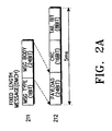
- FIGS. 2A, 2B and 2C illustrate frame structures of a first length frame message for the dedicated control channel, a second length frame message for the dedicated control channel when carrying signaling data, and a second length frame message for the dedicated control channel, when carrying traffic data, respectively.
- the first length frame message of FIG. 2A is 5ms in duration.
- Reference numeral 211 denotes a 24 bit fixed length message body frame of an upper layer, preceded by a 1 bit message type flag.
- Reference numeral 212 denotes a first length frame communicated in a physical layer (i.e., the data bits of frame 212 are wirelessly transmitted).
- Frame 212 is composed of a 24 bit payload field, a 16 bit CRC field and an 8 bit tail bit field.
- the information of the 24 bit message body segment of frame 211 in the upper layer is placed in the 24 bit payload frame segment of frame 212 of the physical layer.
- the fixed length message may be a DMCH (Dedicated MAC (Medium Access Control) Channel) message, a DSCH (Dedicated Signaling Channel) message, or another type of message.
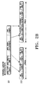
- FIG. 2B illustrates the second length frame (20ms duration), in which reference numeral 221 denotes a variable length control message of the upper layer and reference numeral 222 denotes a sequence of second length (20ms) control message frames wirelessly communicated in the physical layer.
- the variable length message may be the DSCH message.
- the data within the variable length message body of the DSCH message is distributed in the payload segments of the 20ms frames.
- the payload segment of each 20ms frame in the sequence, except for the last 20ms frame, is 168 bits.
- the payload segment of the last 20ms frame can be anywhere between 1 and 168 bits long.
- the number of 20ms frames in the transmitted sequence depends on the number of bits in the message body of the upper layer message.
- FIG. 2C illustrates a second length traffic frame of 20ms period, in which reference numeral 231 denotes a traffic structure of the upper layer and reference numeral 232 denotes a second length traffic frame communicated in the physical layer.
- the traffic may be Dedicated Traffic Channel (DTCH) traffic.
- DTCH Dedicated Traffic Channel
- the user traffic data is distributed among the payload portions of the 20ms traffic frames in a similar manner as the control message data of FIG. 2B.
- the dedicated control channel has the functions of delivering packet data service-related control messages (e.g., a packet traffic channel allocation message, a layer 3 control message, etc.), delivering the IS-95 control message by encapsulating, delivering a short user packet, and transmitting a power control bit (PCB) through the forward link.
- packet data service-related control messages e.g., a packet traffic channel allocation message, a layer 3 control message, etc.
- PCB power control bit
- the frame length of the dedicated control channel is allowed to vary.
- a frame length obtained by dividing a reference frame length by an integer should be used to improve the throughput.
- the reference frame length is 20ms
- the 5ms frame is used. In this way, it is possible to increase the throughput and decrease the traffic delay, as compared with the case where the 20ms frame shown in FIG. 2B is used.
- This can also be applied to the traffic channels to efficiently process the short control messages if the traffic channel be used as user traffic data.
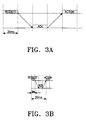
- FIG. 3A illustrates a transmission time interval for the second length frame message (i.e., 20ms frame message)
- FIG. 3B illustrates a transmission time interval for the first length frame message (i.e., 5ms frame message).
- the time required to send a request message through the dedicated control channel and take corresponding action after reception of an acknowledge, is 80ms as shown in FIG. 3A when the 20ms frame is used, and is 20ms, as shown in FIG. 3B when the 5ms frame is used.
- the latter represents the case where the respective messages are so short as to be loaded into the 5ms frame, i.e., where the maximum gain in throughput can be obtained with the 5ms frame.
- the reason that the throughput is increased is because the signals are efficiently transmitted, thereby increasing the time in which the actual user data can be transmitted.
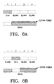
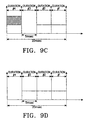
- FIGS. 8A and 8B illustrate the transmission powers with respect to the time when the first length frame message is intermixed with the second length frame message.
- the term intermixed with is intended to mean that the shorter message is inserted into the longer frame message to either delay the longer frame message, or to permanently replace the corresponding portion of the longer frame message. When a permanent replacement occurs, the replaced portion is not transmitted, and the tail portion ofthe longer frame message is transmitted undelayed.
- the 20ms message frame is shown divided into four 5ms message frame durations #1, #2, #3, and #4.
- the 5ms frame can be inserted and transmitted at one of the four divided durations #1-#4 of the 20ms frame. That is, the 20 ms frame message is interrupted , and the 5ms frame is inserted. In this case, a 5ms segment of data of the 20ms frame message is lost (i.e., not transmitted) at the interval (duration) where the 5ms shorter frame is transmitted, but the lost data can be restored at a receiver through decoding of an error correction code.
- the transmitter can increase the transmission power in the intervals following the duration where the 5ms frame data is lost.
- the transmitter when the 5ms frame is intermixed with the 20ms frame at the first duration # 1, the transmitter will increase the transmission power by 33% at the succeeding durations #2, #3 and #4 of the 20ms frame. Also, as shown in FIG. 8B, when the 5ms frame is intermixed with the 20ms frame at the second duration #2, the transmitter will increase the transmission power by 50% at the succeeding durations #3 and #4 of the 20ms frame.
- an interleaver for the 20ms frame is designed such that the bits corresponding to the lost 5ms frame data can be dispersed by a row permutation technique. In this manner, it is possible to immediately transmit the 5ms frame even during transmission of the 20ms frame, thereby reducing the transmission time. A detailed description will be given with reference to FIGS. 9A through 14B.
- FIGS. 8A and 8B show examples of continuing to transmit the remaining frame data of the 20ms frame immediately after the first length frame message is transmitted, it is also possible to delete the remaining frame data of the second length frame message.
- the dedicated control channel and the traffic channel are used in a control hold state and an active state out of the states for performing the procedures for the packet data service.
- Table 2 Shown in Table 2 is the relationship between the "logical" channels and the "physical" channels for the forward and the reverse links.
- the physical channels are the channels that are wirelessly transmitted.
- the data carried by the physical channels is derived from the respective logical channels. Forward Link Reverse Link Logical CH Physical CH Logical CH Physical CH Control Hold State DMCH Dedicated DMCH Dedicated DSCH Control CH DSCH Control CH Active State DMCH Dedicated DMCH Dedicated DSCH Control CH DSCH Control CH DTCH DTCH DTCH Packet Traffic CH DTCH Packet Traffic CH
- the dedicated MAC channel is a forward or reverse channel necessary for transmission of a Medium Access Control (MAC) message, and is a one-to-one channel allocated in the control hold state and the active state for the packet service.
- the message of the dedicated MAC channel in the logical channel essentially becomes the message of the dedicated control channel in the physical layer.
- the dedicated signaling channel (DSCH) is a forward or reverse channel necessary for transmission of the layer 3 signaling message, and is a one-to-one channel (i.e., unshared channel) allocated in the control hold state and the active state for the packet service.
- the dedicated traffic channel is a forward or reverse channel necessary for transmission of the user data, and is a one-to-one channel allocated in the active state for the packet service.
- the control hold state in Table 2 means a state where although the dedicated MAC channel DMCH and the dedicated signaling channel DSCH are allocated to the forward and reverse links, an RLP (Radio Link Protocol) frame with the user data packet cannot be exchanged because the dedicated traffic channel DTCH is unestablished.
- the active state means a state where the channels DMCH, DSCH and DTCH are allocated to the forward and reverse links so that the RLP frame with the user data packet can be exchanged.
- FIGS. 2A to 2C show the logical channel message frames or data mapped into the physical channel frames.
- reference numerals 211, 221 and 231 denote the logical channel message frames
- reference numerals 212, 222 and 232 denote the physical channel message frames.
- the ensuing discussion relates to the structures and operations of the first length frame and the second length frame for the dedicated control channel.
- the frame length of the dedicated control channel varies dynamically according to the type of the message.
- the frame length is determined every 5ms.
- request/allocation for the forward and reverse packet traffic channels is made using a 5ms request/acknowledge message.
- the forward packet traffic channel allocation which begins at the base station is independent of the reverse packet traffic channel allocation which begins at the mobile station.
- the connection control messages include a packet traffic channel request message, a packet traffic channel allocation message and a packet traffic channel acknowledge message. These messages are transmitted through the DMCH among the logical channels.
- Table 3 shows channel allocation message fields for the reverse packet traffic channel, for the first length message frame of 5ms.
- Reverse Packet Traffic Channel Allocation Message (24 bits) Field Length (bits) Header Information 5 Sequence 3 Start Time 2 Allocated Rate 4 Allocated Duration 3 Reserved Bits 7
- the 24-bit fixed length message in the form of Table 3 is transmitted with the 5ms frame, shown in FIG. 2A, of the dedicated control channel.
- FIG. 4 is a flowchart illustrating a procedure for allocating and releasing the packet traffic channel through the dedicated control channel, while the system transitions from the control hold state to the active state and then transitions again from the active state to the control hold state. It is assumed in step 411 that the base station and the mobile station maintain the control hold state in which the dedicated control channel is connected. In this state, the mobile station generates a control message for requesting allocation of the reverse packet traffic channel through the dedicated MAC channel DMCH and sends it through the physical channel, in step 413. The base station then generates a control message for allocating the reverse packet traffic channel via the dedicated MAC channel DMCH and sends the generated control message via the physical channel, in step 415.
- the base station and the mobile station transition to the active state where the packet traffic channel is allocated to communicate the packet data, in step 417.
- the mobile station initializes a T active timer in step 419 to check the time at which transmission of the packet data is discontinued.
- the active state is maintained and then the step 419 is repeated to initialize the T active timer.
- the mobile station perceives this in step 421, and generates a control message for requesting release of the reverse packet traffic channel through the dedicated MAC channel DMCH and sends the generated control message through the physical channel, in step 423.
- the base station In response to the control message, the base station generates a response control message for release of the reverse packet traffic channel via the dedicated MAC channel DMCH and sends the generated control message via the physical channel, in step 425. Subsequently, the base station and the mobile station release the reverse traffic channel and transition to the control hold state, in step 427, preparing for the next state.
- the mobile station during the procedure of requesting and allocating the reverse packet traffic channel, the mobile station generates the reverse packet traffic channel request message including the requested channel data rate information and sends it to the base station.
- the base station analyzes the received message to determine whether or not the requested parameter can be supported and sends, in response to the request message, the reverse packet channel allocation control message of Table 3 to the mobile station according to the determination.
- the packet traffic channel releasing process is performed after a lapse of the time set in the T active timer.
- the variable length message In a transmission mode for the variable length frame, the variable length message according to the IS-95 standard is divisionally loaded into the 20ms frames of the dedicated control channel, as shown in FIG. 2B.
- the transmission modes may include a mode for transmitting the frame without error detection and correction by ACK/NACK (acknowledge/negative acknowledge), a mode where ACK/NACK occurs when an entire variable length message is received and retransmission is performed for the entire variable length message, and a mode where ACK/NACK is performed for the respective frames.
- ACK/NACK acknowledge/negative acknowledge
- the RLP frames with the user traffic is divisionally loaded into the 20ms frames of the dedicated control channel, as shown in FIG. 2C.
- the user data transmission mode can be used in the event that it is inefficient to establish the packet traffic channel for transmitting the data because there is a small amount of the data to transmit.
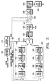
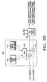
- a message buffer 511 temporarily stores a frame message communicated through the dedicated channel.
- the message buffer 511 should have a proper size to store one or more second length frames of 20ms.
- the message buffer 511 interfaces a frame message between a higher layer processor (not shown) and a modem controller 513 or between a user data generator (not shown) and the modem controller 513.
- the higher layer processor sets a flag after storing the frame message in the message buffer 511, and the modem controller 513 clears the flag after reading the frame message, so as to prevent over-writing and over-reading.
- the modem controller 513 After reading the frame message stored in the message buffer 511, the modem controller 513 analyzes a header of the frame message to detect a message type, outputs message data (or payload) to be transmitted through the dedicated channel according to the detected message type, and outputs frame select signals according to the detected message type.
- the types of the frame data include the first length frame data of FIG. 2A and the second length frame data of FIG. 2B.
- the modem controller 513 outputs different sized frame messages according to the analysis. That is, for the 5ms frame data, the modem controller 513 outputs first frame data of 24 bits having the structure of Table 3 at a first output terminal 541; for the 20ms frame data, the modem controller 513 outputs second frame data of 172 bits at a second output terminal 542.
- the modem controller 513 determines absence/presence of the frame data to control an output of the dedicated control channel. That is, the modem controller 513 generates a first frame select signal upon detection of the first length frame message of 5ms, and generates a second frame select signal upon detection of the second length frame message of 20ms. In addition, the modem controller 513 generates a first gain control signal in the event where is the 20ms or 5ms frame message to transmit. However, in the event that the 5ms frame message is intermixed with the 20ms frame message, the modem controller 513 generates a second gain control signal for increasing the transmission power at the remaining portion of the 20ms frame message following the duration where the frame messages are intermixed. Moreover, when there is no frame message to transmit, the modem controller 513 generates a third gain control signal for restraining the signal transmission on the dedicated control channel.
- the modem controller 513 generates the first frame select signal and the first gain control signal, to output the first length frame data at the first output terminal 541. Also, the modem controller 513 generates the second frame select signal and the second gain control signal, to output the second length frame data at the second output terminal 542. In addition, when the 5ms frame message is intermixed with the 20ms frame message during transmission of the 20ms frame message, the modem controller 513 outputs the first and second length frame data at the first and second output terminals, respectively, and generates the first frame select signal for selecting the first length frame message of 5ms for the duration where the first length frame message is output.
- the modem controller 513 After transmission of the first length frame message of 5ms, the modem controller 513 generates the second frame select signal for selecting the second length frame data for the remaining duration of the 20ms frame message and generates the second gain control signal for increasing the transmission power of the second length frame data being transmitted at that moment. However, when there is no frame message to transmit, the modem controller 513 generates the third gain control message to block a transmission path of the dedicated control channel.
- the first length frame data refers to a first length bit stream of 5ms (consisting of 24 bits) and the second length frame data refers to a second length bit stream of 20ms (consisting of 172 bits).
- a CRC (Cyclic Redundancy Check) generator 515 adds 16 CRC bits to the first length frame data of 24 bits output from the modem controller 513 to render it possible to determine the frame quality (i.e., determine whether or not the frame has an error) at the receiver. Specifically, upon reception of the 5ms frame data, the CRC generator 515 generates 16 CRC bits to output the 40-bit frame data, under the control of the modem controller 513.
- a tail bit generator 517 generates tail bits necessary for termination of an error correction code. This tail bit generator 517 generates and adds the tail bits at the end of the first length frame message so as to allow an encoder 519 at the following stage to encode the message by the first length frame unit. Specifically, the tail bit generator 517 generates 8 tail bits and adds them to the output of the CRC generator 515, thereby to output the frame message of 48 bits as represented by reference numeral 212 of FIG. 2A.
- the encoder 519 encodes an output of the tail bit generator 517.
- encoder 519 can be a convolutional encoder or a turbo encoder using an encoding rate of 1/3 and a constraint length of 9, thus generating 144 encoded bits (or symbols).
- An interleaver 521 interleaves the 5ms frame message output from the encoder 519. That is, the interleaver 521 rearranges the symbols within the frame by the first frame length unit of 5ms, so as to improve a tolerance for burst errors.
- the interleaved output of the interleaver 521 will be called a first frame message.
- the CRC generator 515, the tail bit generator 517, the encoder 519 and the interleaver 521 constitute a first frame message generator 550 for generating the first frame message by receiving the first frame data.
- a CRC generator 516 adds 12 CRC bits to the second length frame data of 172 bits output from the modem controller 513 to render it possible to determine the frame quality (i.e., determine whether or not the frame has an error) at the receiver. Specifically, upon reception of the 20ms frame data, the CRC generator 516 generates 12 CRC bits to output the 184-bit frame data, under the control of the modem controller 513.
- a tail bit generator 518 generates tail bits necessary for termination of an error correction code. This tail bit generator 518 generates and adds the tail bits at the end of the second length frame message so as to allow an encoder 520 at the following stage to encode the message by the second length frame unit. Specifically, the tail bit generator 518 generates 8 tail bits and adds them to the output of the CRC generator 516, thereby to output the frame message of 192 bits as represented by reference numeral 222 of FIG. 2B.
- the encoder 520 encodes an output of the tail bit generator 518.
- the encoder 520 used in the embodiment, is a convolutional encoder or a turbo encoder using an encoding rate of 1/3 and a constraint of length of 9. Therefore, the encoder 520 generates 576 encoded bits (or symbols).
- An interleaver 522 interleaves the 20ms frame message output from the encoder 520. That is, the interleaver 522 rearranges the symbols within the frame by the second frame length unit of 20ms, so as to improve a tolerance for a burst error. In the present embodiments, the interleaved output of the interleaver 522 will be called a second frame message.
- the CRC generator 516, the tail bit generator 518, the encoder 520 and the interleaver 522 constitute a second frame message generator 560 for generating the second frame message by receiving the second frame data.
- a mutliplexer 523 selects the outputs of the first and second interleavers 521 and 522 according to the frame select signal SCTL output from the modem controller 513. That is, the multiplexer 523 selects the output of the first interleaver 521 in response to the first frame select signal and the output of the second interleaver 522 in response to the second frame select signal.
- a multiplexer can be used for the mutliplexer 523.
- the modem controller 513 and the selector 523 serve as an inserter for intermixing the first frame message with the second frame message when the first length frame message is generated during transmission of the second length frame message or when the first and second frame messages are generated simultaneously.
- a signal mapping and multiplexing block 525 maps a frame message output from the multiplexer 523 and multiplexes the mapped frame message to first and second channels. That is, the signal mapping and multiplexing block 525 maps the frame message by converting a control signal of the logic “ 1 " to “-1” and a control signal of the logic “0” to “+1", and outputs the odd-numbered control signals to the first channel and the even-numbered control signals to the second channel.
- a control bit inserter 531 inserts a control bit into the output of the signal mapping and multiplexing block 525.
- This inserted control bit may be a power control bit (PCB) for controlling the reverse link power of the mobile station.
- PCB power control bit
- Gain controllers 527 and 528 control gains of the corresponding channel signals output from a control bit puncturer 531according to the gain control signal GCTL output from the modem controller 513. That is, the gain controllers 527 and 528 output the input signals, as they are, in response to the first gain control signal, increase the gains of the input signals to increase the transmission power in response to the second gain control signal, and decrease the gains of the input signals to zero to discontinue an output of the dedicated control channel in response to the third gain control signal. Accordingly, the gain controllers 527 and 528 form or block the paths for the frame message on the dedicated control channel according to the gain control signals output from the modem controller 513.
- the gain controllers 527 and 528 perform a DTX (Discontinuous Transmission) mode of operation, in which the path of the dedicated control channel is formed according to the gain control signals when there is the frame message to transmit, and the path of the dedicated channel is blocked when there is no frame message to transmit.
- the gain controllers 527 and 528 increase the power of the output signals when the 5ms frame message is intermixed with the 20ms frame message under the control of the modem controller 513.
- the gain controllers 527 and 528 constitute a power controller for controlling the transmission power of the signals.
- a serial-to-parallel (S/P) converter 529 multiplexes input signals so as to propagate the control signals output from the gain controllers 527 and 528 through the multicarrier signal.
- An orthogonal code modulator 533 generates an orthogonal code according to the orthogonal code number and length of the allocated channel and orthogonally modulates the frame message by multiplying the frame message by the generated orthogonal code.
- a Walsh code, a quasi-orthogonal code or an m-chip resistance code can be used for the orthogonal code.
- a spreading modulator 535 spreads the orthogonally modulated signal output from the orthogonal code modulator 533 by combining it with a spreading sequence such as a pseudo-random noise (PN) sequence.
- PN pseudo-random noise
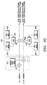
- the structures of the orthogonal code modulator 533 and the spreading modulator 535 are shown in FIGS. 6A to 6C.
- a Walsh code generator 615 generates a Walsh code for the dedicated control channel.
- the Walsh code is the orthogonal code that is the most widely used.
- Multipliers 611 and 613 generate orthogonal modulation signals by combining the corresponding I-and Q-channel input signals with the Walsh code output from the Walsh code generator 615.
- the spreading modulator 535 spreads the corresponding I-and Q-channel signals output from the multipliers 611 and 613 with PN sequences PNi and PNq provided from a spreading sequence generator (not shown).
- a complex PN spreader may be used for the spreading modulator 535.
- the quasi-orthogonal codes can be used to expand the number of the orthogonal codes. That is, there exists an orthogonal code set according to a predetermined code length: for example, when the code length is 256, there exists a 256x256 Walsh code set from which N 256x256 quasi-orthogonal code sets (where N is a natural number) can be produced systematically.
- Such quasi-orthogonal code sets have the minimized interference between the quasi-orthogonal code channels and the Walsh code channels and have a fixed correlation value between the quasi-orthogonal codes.
- FIG. 6B illustrates a quasi-orthogonal code generator 533 and a spreading modulator 535.
- a Walsh code generator 615 generates a Walsh code according to the Walsh code number and length of the allocated channel
- a quasi-orthogonal code mask 617 generates a quasi-orthogonal mask signal.
- An exclusive OR gate 619 XORs the Walsh code and the quasi-orthogonal code mask signal bit by bit to generate a quasi-orthogonal code.
- Multipliers 611 and 613 multiply the corresponding I- and Q-channel signals by the quasi-orthogonal code output from the XOR gate 619 to spread the frame message of the forward link dedicated control channel.
- the spreading modulator 535 spreads the corresponding I-and Q-channel signals output from the multipliers 611 and 613 with the aforementioned PN sequences Pni and PNq.
- the quasi-orthogonal code is generated by multiplying the Walsh code by the quasi-orthogonal code mask signal (or XORing the Walsh code and the quasi-orthogonal code mask signal when the data is represented by "0" and "1").
- a suitable quasi-orthogonal code generator is disclosed in detail in Korean patent application No. 46402/1997, entitled “Quasi-orthogonal Code Generation Device and Method for Mobile Communication System", filed by the applicant of the present invention. With use of the quasi-orthogonal code, it is possible to increase the number of the encoded channels by a factor of N, allowing many traffic channel users to use the unique dedicated control channels.
- FIG. 6C illustrates a scheme for generating a quasi-orthogonal code according to another embodiment.
- a Walsh code generator 615 generates a Walsh code for the dedicated channel.
- Multipliers 611 and 613 multiply the corresponding I- and Q-channel signals by the Walsh code output from the Walsh code generator 615 to generate orthogonal modulation signals.
- a PN mask 653 generates a PN mask signal, and a PNi generator 655 generates a PN sequence PNi for the I channel.
- An AND gate 657 ANDs the PN mask signal and the PN sequence PNi bit by bit to generate an I-channel spread signal.
- a PN mask 654 generates a PN mask signal
- a PNq generator 656 generates a PN sequence PNq for the Q-channel.
- An AND gate 658 ANDs the PN mask signal and the PN sequence PNq bit by bit to generate a Q-channel spread signal.
- the PN sequences generated by AND-ing the specific PN masks with the respective outputs of the PNi and PNq generators 655 and 656 are used in generating the quasi-orthogonal codes. In this way, one quasi-orthogonal code set is generated for each PN mask. Therefore, when N different PN masks are used, it is possible to expand the number of the encoded channels, which is similar to the method of generating N quasi-orthogonal code sets using the quasi-orthogonal code generator.
- frame staggering which is used interchangeably with frame offset, means an operation of offsetting the frames of the respective data channels by a predetermined time on the basis of the system time.
- the frame offset is applied to obtain the result of dispersing the frame processing load when processing the transmission and reception data at the mobile station or the base station. That is, the frame staggering is implemented for the efficient use of the common resources (i.e., trunks) for processing the data.
- the traffic channel frames are offset by a multiple of the power control duration of 1.25ms, and the maximum frame offset is 18.75ms which is 15 times the duration 1.25ms.
- the frame length (5ms or 20ms) of the message to be transmitted is determined in the modem controller 513. That is, the modem controller 513 determines the frame length by examining the header information representing whether the frame message stored in the message buffer 511 is a 24-bit fixed length frame message or a variable length frame message. When the header information represents the 24-bit fixed length frame message, it is determined that the frame message has the 5ms frame length. When it represents the variable length frame message, it is determined that the frame message has the 20ms frame length.
- the modem controller 513 outputs the input frame data to the first frame message generator 550 or the second frame message generator 560 according to the frame length determination, generates the frame select signal SCTL for selecting the first frame message generator 550 or the second frame message generator 560, and generates the gain control signal GCTL for outputting or restraining the frame message output.
- Table 4 shows the control signals generated from the modem controller 513.
- the numerals in sub-blocks 515, 517, 519 and 521 of the first frame message generator 550 and the numerals in sub-blocks 516, 518, 520 and 522 of the second frame message generator 560 represent the bit numbers according to the frame lengths of 5ms and 20ms.
- the modem controller 513 controls the dedicated channel in the DTX mode. That is, in the preferred embodiment, the signaling message and the MAC-related message for the data service are transmitted/received through the dedicated control channel, contributing to an effective use of the channel capacity.
- the IS-95 system is structured to multiplex the voice traffic and the signaling traffic, so that the voice and signaling channels should be normally opened for the data service.
- the dedicated channel of the invention operates in the DTX mode, it is not necessary to normally open the channel for the control signal. When there is no signal information to transmit, it is possible to suppress a transmission power in a DTX gain controller, thus effectively utilizing the radio capacity.
- the gain controllers 527 and 528 may be positioned following a spreading stage.
- the modem controller 513 applies the 5ms frame data to the first frame message generator 550 and the 20ms frame data to the second frame message generator 560.
- the first and second interleavers 521 and 522 output the 5ms and 20ms frame messages, respectively.
- the multiplexer 523 selects the output of the first interleaver 521 in response to the first frame select signal, and the gain controllers 527 and 528 transfer the output signals, as they are, in response to the first gain control signal. Accordingly, for the duration #1, the 5ms frame message is output as its original input signal level. After transmission of the 5ms frame message for the duration #1, the multiplexer 523 selects the output of the second interleaver 522 in response to the second frame select signal, and the gain controllers 527 and 528 increase the transmission power of the 20ms frame message output from the multiplexer 523 in response to the second gain control signal.
- the transmission power of the 20ms frame data is increased by 33% as compared with the input power level.
- the 5ms frame message is received at the duration #2 during transmission of the 20ms frame message received at the duration #1.
- the modem controller 513 applies the 20ms frame message to the second frame message generator 560 and generates the second frame select signal and the first gain control signal.
- the modem controller 513 applies the 5ms frame message to the first frame message generator 550 and the 20ms frame message to the second frame message generator 560 and generates the first frame select signal and the first gain control signal.
- the 20ms frame message is output in the original signal level for the duration #1
- the 5ms frame message is output in the original signal level for the duration #2.
- the multiplexer 523 selects the output of the second interleaver 522 in response to the second frame select signal, and the gain controllers 527 and 528 increase the gain of the 20ms frame message output from the multiplexer 523 in response to the second gain control signal.
- the gain is increased by 50% as compared with the input signal level.
- a first intermixing method when the shorter frame message is generated during transmission of the longer frame message, the shorter frame message is transmitted in its entirety (e.g., in a 5ms interval), delaying transmission of the longer frame message, and the remaining portion of longer frame message is transmitted after transmission of the shorter frame message.
- the short frame message and the longer frame message are wholly transmitted, the performance degradation may not occur during decoding at the receiver.
- the sum of the two frame messages will exceed the time limit.
- a second intermixing method when the shorter frame message is generated during transmission of the longer frame message, the shorter frame message is transmitted in place of a portion of the longer frame message, and the portion that was replaced is never transmitted. The tail end of the longer frame message is then transmitted in an undelayed fashion. In this method, the data of the longer frame message may be lost at the replaced portion, causing the decoding performance degradation. However, this problem can be minimized depending on how to design a symbol distributor for the longer frame message.
- the decoding performance depends on the position of the replaced symbols in one frame duration. By searching for a position having the best decoding performance for the replaced frame message and replacing the frame message at this position, the problem of the decoding performance degradation may be solved.
- a free distance d free representing the minimum Hamming distance between encoded symbols
- a transfer function representing an upper limit formula of a bit error rate and a distribution of the Hamming distance between the symbols (See “Error Correction Coding: Fundamentals and Application” - Shu Lin/Daniel J. Costello, Jr.).
- the parameters are measured for the respective replacement positions to search for the preferable replacement position. If it is possible to move the searched positions to the position to be punctured in the intermixing process, the problem which arises in the intermixing process may be solved.
- the power loss can be compensated for by increasing the signal power of the remaining portion of the longer frame message as much as the lost power.
- the searched replacement positions are measured through experiments to verify the performance. Thereafter, the symbol distributor is designed for moving the symbols at the searched positions to the positions to be punctured in the intermixing process.
- An interleaver may be used for the symbol distributor.
- the 5ms frame is intermixed with the 20ms frame, and the 20ms frame of 192 bits is encoded into the convolutional code of a coding rate 1/3.
- the number of the encoded symbols is 576.
- the 5ms frame refers to the first length frame message having the frame length of 5ms
- the 20ms frame refers to the second length frame message having the frame length of 20ms.
- the 5ms frame is one fourth the length of the 20ms frame, there are four possible intermixing positions. That is, when the 20ms frame is divided into four durations, the 5ms frame can be intermixed with the 20ms frame at any one of the four divided durations.
- the 20ms frame data is lost for the interval in which 5ms frame data is transmitted.
- the lost data of the 20ms frame is restored through the decoding function of the error correction code at the receiver.
- the transmitter increases the transmission power at the remaining durations following the lost 5ms duration.
- the power of the 20ms frame is increased by about 33% at the following durations #2, #3 and #4.
- the power of the 20ms frame is increased by about 50% at the following durations #3 and #4.
- the power of the 20ms frame is increased by about 100% at the following duration #4.
- the decoding performance may be deteriorated as compared to the above three cases.
- the interleaver for the 20ms frame is designed such that the symbols corresponding to the 5ms duration, to be deleted by performing row permutation, should be dispersed.
- the free distance is 11 for the delete matrix #1, 12 for the delete matrix #2, 10 for the delete matrix #3 and 10 for the delete matrix #4.
- the free distance represents the minimum Hamming distance between the symbols and the Hamming distance represents the number of the skewed bits between the encoded symbols. As the Hamming distance is getting greater, the decoding performance is increased.
- the delete matrixes # 1 and #2 have the better properties in terms of the free distance, as compared with the delete matrixes #3 and #4. Further, although the delete matrix #1 has the better property than that of the delete matrix #2 in terms of the free distance, the delete matrix #2 has the better property than that of the delete matrix #1 in terms of the distribution of the Hamming distance between the encoded symbols.
- Table 5 Shown in Table 5 is an interleaver designed to have the puncturing form according to the delete matrix #1. 32x18 arrangement of the encoded symbols 1 33 65 97 129 161 193 225 257 289 321 353 385 417 449 481 513 545 5 37 69 101 133 165 197 229 261 293 325 357 389 421 453 485 517 549 9 41 73 105 137 169 201 233 265 297 329 361 393 426 457 489 521 553 13 45 77 109 141 173 205 237 269 231 333 365 397 428 461 493 525 557 17 49 81 113 145 181 209 241 273 235 337 369 401 433 465 497 529 561 21 53 85 117 149 181 213 245 277 309 341 373 405 437 469 501 533 566 25 57 89 121 153 185 217 249 281
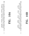
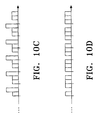
- FIGS. 10A through 10D illustrate the symbol forms of the 20ms frame Transmitted by the interleaver designed according to the delete matrix #1 for the respective intermixing methods.
- FIG. 10A illustrates the case where the 5ms frame is intermixed with the 20ms frame at the duration #1.
- the puncturing is performed in the order of first symbol data S 10 , second symbol data S 21 , third symbol data S 32 , fourth symbol data S 40 and fifth symbol data S 51 according to the delete matrix #1.
- the symbols have the equivalent powers as illustrated in the figure.
- FIG. 10B illustrates the case where the 5ms frame is intermixed with the 20ms frame at the duration #2.
- the puncturing format is similar to that of FIG.
- FIG. 10A illustrates the case where the 5ms frame is intermixed with the 20ms frame at the duration #3.
- the puncturing form is similar to that described above, and the respective symbols have different powers according to the durations to which they belong. For example, the symbols belonging to the duration #2 and #3 have the original power, and the symbols belonging to the duration #4 have about twice as much power as compared with the original power.
- FIG. 10D illustrates the case where the 5ms frame is intermixed with the 20ms frame at the duration #4.
- the puncturing format is the same as that described above, and the symbols have the original power.
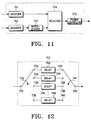
- FIG. 11 illustrates a scheme for intermixing frame messages of different lengths according to an embodiment of the present invention.
- an interleaver 713 is designed to have the property of Table 5 according to the delete matrix #1. Therefore, the specification will present the scheme designed according to the delete matrix #1, by way of example.
- an encoder 711 generates an encoded first length frame message of 5ms, and an output of the encoder 711 is interleaved through a undepicted interleaver.
- An encoder 712 generates an encoded second length frame message of 20ms, and the interleaver 713 interleaves the encoded 20ms frame message output from the encoder 712 to rearrange the symbols within the frame in such a manner that the corresponding symbols are punctured according to the delete matrix #1.
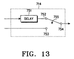
- a selector 714 selects the output of the encoder 711 or the output of the interleaver 713 according to the frame select signal. That is, the selector 714 selects the output of the encoder 711 in response to the first frame select signal, and selects the output of the interleaver 713 in response to the second frame select signal.
- a multiplexer can be used for the selector 714.
- a power controller 715 controls a gain of the signal output from the selector 714 according to the gain control signal. That is, the power controller 715 outputs the input signal, as it is, without gain control in response to the first gain control signal, increases the gain of the input signal to increase the output power in response to the second gain control signal, and controls the gain of the input signal to zero in response to the third gain control signal. When the gain is zero, there is no output signal so that the output of the channel is cut off.
- the encoder 711 encodes the first frame data input and generates the first length frame message to the selector 714.
- the encoder 712 encodes the second data input and generates the second length frame message to the interleaver 713.
- the interleaver 713 then rearranges the symbols within the second length frame message so that the symbols are punctured in accordance with the delete matrix #1 for the respective cases of FIGS. 9A to 9D.
- the structure of the interleaver 713 is illustrated in FIG. 12.
- the interleaver 713 consists of 32 delays 743-746.
- a switch 732 connects a node 731 to a node 733 to output a first symbol to the delay 743, and connects the node 731 to a node 734 to output a second symbol to the delay 744.
- the switch 731 connects again the node 731 to the node 733 to output a 33rd symbol to the delay 743.
- a switch 741 connects a node 742 to a node 737 to output the symbols stored in the delay 743.
- the switch 741 connects the node 742 to an output node of the fifth delay to output the symbols stored in the fifth delay.
- the symbols stored in the first, fifth, ninth, thirteenth, seventeenth, twenty-first, twenty-fifth and twenty-ninth delays are output in sequence for the duration #1 of the 20ms frame; the symbols stored in the second, sixth, tenth, fourteenth, eighteenth, twenty-second, twenty-sixth and thirtieth delays are output in sequence for the duration #2 of the 20ms frame; the symbols stored in the third, seventh, eleventh, fifteenth, nineteenth, twenty-third, twenty-seventh and thirty-first delays are output in sequence for the duration #3 of the 20ms frame; and the symbols stored in the fourth, eighth, twelfth, sixteenth, twentieth, twenty-fourth, twenty-eighth and thirty-second delays are output in sequence for the duration #4 of the 20ms frame.
- the values output from the interleaver 713 are input to the selector 714 and intermixed with 5ms frame applied to another input end of the selector 714.
- FIG. 13 illustrates the structure of the selector 714. If the 5ms frame is input while a switch 755 connects a node 754 to a node 753 to output the 5ms frame for the duration #1, the input 5ms frame is temporarily delayed by the delay 751. After passage of the duration #1, the switch 755 connects the node 754 to a node 752 to output the delayed 5ms frame symbols for the duration #2. Thus, the symbols of the 20ms frame are deleted at the duration #2. After passage of the duration #2, the switch 755 connects again the node 754 to the node 753 to output the remaining 20ms frame symbols.
- Such intermixed frames are input to the power controller 715 which outputs the symbols of the 5ms frame, as they are, and outputs the symbols of the remaining 20ms frame with an increased power.
- the encoded 20ms frame output from the encoder 712 is punctured as shown in the delete matrix #2.
- the selector 714 receives in sequence the symbols output from the first, fifth, ninth, thirteenth, seventeenth, twenty-first, twenty-fifth and twenty-ninth delays in the interleaver 713 and outputs the received symbols to the power controller 715, in response to a first select signal. Further, the selector 714 outputs the symbols of the 5ms frame delayed in the delay 751 to the power controller 715 in response to a second select signal.
- the selector 714 receives in sequence the symbols output from the third, seventh, eleventh, fifteenth, nineteenth, twenty-third, twenty-seventh, thirty-first, fourth, eighth, twelfth, sixteenth, twentieth, twenty-fourth, twenty-eighth and thirty-second delays in the interleaver 713 and outputs the received symbols to the power controller 715, in response to the first select signal. That is, it implies that the symbols of the second, sixth, tenth, fourteenth, eighteenth, twenty-second, twenty-sixth and thirtieth delays corresponding to the duration #2 of the 20ms frame are deleted.
- a performance of such a frame intermixing scheme depends on the generator polynomial of the encoders and the interleaver.
- the delete matrix having the good performance measurement is selected for the respective cases and then, the interleaver is designed accordingly.
- FIGS. 14A an 14B illustrate the performances of the punctured frames using the delete matrix #1 and the delete matrix #2, respectively. More specifically, FIG. 14A illustrates the performances of the interleaver designed using the delete matrix #1, for the respective intermixed cases #1 to #3. FIG. 14B illustrates the performances of the interleaver designed using the delete matrix #2, for the respective intermixed cases #1 to #3. ,
- FIGS. 14A and 14B both show that the intermixed case # 1 provides the best performance and the intermixed case #3 provides the worst performance.
- the symbol distributor is designed according to the delete matrix #1 in the frame matrix scheme.
- the dedicated control channel transmission device outputs the 5ms frame message at the corresponding time and thereafter, transmits the remaining 20ms frame message with the increased power.
- the frame message was encoded at the 1/3 coding rate in the encoding process, the receiver can perform the error correction with respect to the data loss.
- the second interleaver 522 should be so designed as to uniformly disperse the encoded data.
- FIGS. 8A and 8B show the examples of intermixing the 5ms frame message and the 20ms frame message, it can be understood that the frame message transmission capability is excellent even in the case where the 5ms frame message and the 20ms frame message are output successively.
- FIG. 5 illustrates the structure of the dedicated channel transmission device for the forward link (from the base station to the mobile station).
- the dedicated control channel transmission device for the forward link should perform a PCB puncturing operation for controlling a transmission power of the mobile station.
- a dedicated channel transmission device for the reverse link does not have to perform the PCB insertion operation.
- the dedicated channel transmission device for the reverse link has the similar structure as that of the dedicated control channel transmission device for the forward link, except for the PCB insertion scheme, the S/P converter (for multicarrier), the spreader structure and the encoding rate of the convolutional encoder.
- the encoding rate of the forward link encoder is 1/3 and the encoding rate of the reverse link encoder is 1/4.
- the dedicated channel transmission device for the reverse link In transmitting the frame message using the reverse dedicated channel, the dedicated channel transmission device for the reverse link also determines the frame length according to the size of the frame message and transmits the frame message according to the determination. Further, the dedicated channel transmission device for the reverse link examines presence/absence of the frame message to transmit through the reverse dedicated channel, to suppress an output of the reverse dedicated channel when there is no frame message to transmit and to form an output path for the reverse dedicated channel only when there is an actual frame message to transmit.
- Shown in FIG. 5 is the multicarrier dedicated channel transmission device for the forward link and shown in FIG. 7 is the single carrier dedicated channel transmission device for the reverse link. Accordingly, it is also possible to construct a single carrier dedicated channel transmission device for the forward link and a multicarrier dedicated channel transmission device for the reverse link.
- a device for receiving the control signals transmitted through the forward or reverse dedicated channel should determine the length of the frame message to process the control signal.
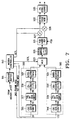
- the dedicated channel reception device for the forward or reverse link can be constructed as shown in FIG. 15.
- a despreader 911 despreads a received signal using a PN sequence and an orthogonal code to receive a dedicated channel signal.
- a diversity combiner 913 combines the multipath signal output from the despreader 911.
- a soft decision generator 915 quantizes the received signal into a multilevel digital value to decode the received signal.
- a first deinterleaver 917 sized to process the 5ms frame message, deinterleaves the 5ms frame message interleaved during transmission to rearrange the bits in the original state.
- a second deinterleaver 918 sized to process the 20ms frame message, deinterleaves the 20ms frame message interleaved during transmission to rearrange the bits in the original state.
- a timer 919 generates a control signal for decoding the data received through the dedicated channel at fixed periods.
- the timer 919 is a 5ms timer capable of decoding the 5ms frame.
- a first decoder 921 is enabled by the control signal output from the timer 919 and decodes the frame message output from the first deinterleaver 917. The first decoder 921 decodes the first length frame message of 5ms.
- a second decoder 923 is enabled by the control signal output from the timer 919 and decodes the frame message output from the second deinterleaver 918. The second decoder 923 decodes the second length frame message of 20ms.
- a first CRC detector 925 receives an output of the first decoder 921 and checks the CRC for the 5ms frame.
- a second CRC detector 927 receives an output of the second decoder 923 and checks the CRC for the 20ms frame.
- the first and second CRC detectors 925 and 927 output a true signal "1" or a false signal "0" as the result signal.
- a frame length decision block 929 analyzes the result signals output from the first and second CRC detectors 925 and 927 to decide the length of the frame message received through the dedicated channel.
- the frame length decision block 929 generates a select signal sell for selecting the first decoder 921 when the first CRC detector 925 outputs the true signal, generates a select signal sel2 for selecting the second decoder 923 when the second CRC detector 927 outputs the true signal, and generates a DISABLE signal for shutting off the outputs of the first and second decoders 921 and 923 when the first and second CRC detectors 925 and 927 both generate the false signal.
- a selector 931 selects the decoded data output from the first and second decoders 921 and 923 according to the output signals of the frame length decision block 929. That is, the selector 931 selects the output of the first decoder 921 when the received frame is a 5ms frame, selects the output of the second decoder 923 when the received frame is a 20ms frame, and shuts off the outputs of both the first second decoders 921 and 923 for the period in which the frame message is not received.
- a modem controller 933 stores the received frame message of the decoded data output from the selector 931 in a message buffer 935.
- the upper layer processor then reads and processes the control message stored in the message buffer 935.
- the modem controller 933 outputs the first length frame message in response to the select signal sell and the second length frame message in response to the select signal sel2.
- the despreader 911 receives the control signal through the dedicated channel, and despreads the received control signal with the PN sequence.
- the control signals received through the dedicated channel are restored to the original frame message by way of the reverse process of transmission.
- the first and second deinterleavers 917 and 918 are sized to process the 5ms and 20ms frame messages, respectively.
- the first decoder 921 decodes the 5ms frame and the second decoder 923 decodes the 20ms frame to process the frame message.
- the first and second CRC detectors 925 and 927 then perform CRC checking for the decoded data output from the first and second decoders 921 and 923, respectively, and output the result values to the frame length decision block 929.
- the frame length decision block 929 then decides the frame length of the received frame message according to the CRC check results.
- the first CRC detector 925 and the second CRC detector 927 alternately generate the true signal for the 20ms duration.
- the frame length decision block 929 generates the select signals sel1 and sel2 according to the output signals of the first and second CRC detectors 925 and 927.
- the selector 931 selects the outputs of the first and second decoders 921 and 923 according to the select signals sel1 and sel2.
- the modem controller 933 also selectively outputs the first length frame message and the second length frame message to the message buffer 935 according to the select signals sel1 and sel2 from the frame length decision block 929. That is, when received the intermixed frame message, the dedicated channel reception device determines the frame length and separately processes the first length frame message and the second length frame message according to the determination.
- the frame length decision block 929 will generate the select signals as shown in Table 7.
- CRC Detector Frame Length Decision Block Selector Decision Results CRC5 CRC20 True False sel1 1 st Decoder Selected 5ms Frame False True sel2 2 nd Decoder Selected 20ms Frame False False DISABLE Decoder Output Off No Frame True True X X X
- the frame length decision block does not determine the corresponding state.
- the CRC5 and CRC20 are both true, it is also possible to determine the received frame as the 5ms frame and to determine both received frames.
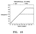
- FIG. 16 illustrates a simulation result for processing variable length frame messages received through the dedicated channel according to the present invention.
- the forward packet traffic channel has a data rate 307.2Kbps, the 20ms fixed frame and 1% FER (Frame Error Rate).
- the CDMA mobile communication system according to the present invention has the following advantages:
Description
| Service | Forward Link Channel | Reverse Link Channel |
| Voice Service | Pilot Channel Voice Traffic Channel | Pilot Channel Voice Traffic Channel |
| High Quality Voice Service | Pilot Channel Voice Traffic Channel Dedicated Control Channel | Pilot Channel Voice Traffic Channel Dedicated Control Channel |
| High Speed Packet Data Service | Pilot Channel Packet Traffic Channel Dedicated Control Channel | Pilot Channel Packet Traffic Channel Dedicated Control Channel |
| Multimedia Service | Pilot Channel Voice Traffic Channel Packet Traffic Channel Dedicated Control Channel Paging Channel (Common Control Channel) | Pilot Channel Voice Traffic Channel Packet Traffic Channel Dedicated Control Channel Access Channel (Common Control Channel) |
| Short Message Service | Pilot Channel Paging Channel (Common Control Channel) | Pilot Channel Access Channel (Common Control Channel) |
| Forward Link | Reverse Link | |||
| Logical CH | Physical CH | Logical CH | Physical CH | |
| Control Hold State | DMCH | Dedicated | DMCH | Dedicated |
| DSCH | Control CH | DSCH | Control CH | |
| Active State | DMCH | Dedicated | DMCH | Dedicated |
| DSCH | Control CH | DSCH | Control CH | |
| DTCH | DTCH | |||
| DTCH | Packet Traffic CH | DTCH | Packet Traffic CH |
| Reverse Packet Traffic Channel Allocation Message (24 bits) | |
| Field | Length (bits) |
| Header Information | 5 |
| | 3 |
| | 2 |
| Allocated | 4 |
| Allocated | 3 |
| Reserved Bits | 7 |
| Frame Message | SCTL | GCTL | Comments |
| 5ms | First Frame Select Signal | Fist Gain Control Signal | Output 5ms Frame Message |
| 20ms | Second Frame Select Signal | Second Gain Control Signal | Output 20ms Frame Message |
| 20ms+5ms | First and Second Frame Select Signals | First and Second Gain Control Signal | Output 5ms Frame Message upon Reception of 5ms Frame Message During Transmission of 20ms Frame Message and Continue to Output the 20ms Frame Message with an Increased Power after Transmission of the 5ms Frame Message |
| X | X | Third Gain Control Signal | Block an Output Path of the Dedicated Channel |


| 32x18 arrangement of the encoded symbols |
| 1 33 65 97 129 161 193 225 257 289 321 353 385 417 449 481 513 545 |
| 5 37 69 101 133 165 197 229 261 293 325 357 389 421 453 485 517 549 |
| 9 41 73 105 137 169 201 233 265 297 329 361 393 426 457 489 521 553 |
| 13 45 77 109 141 173 205 237 269 231 333 365 397 428 461 493 525 557 |
| 17 49 81 113 145 181 209 241 273 235 337 369 401 433 465 497 529 561 |
| 21 53 85 117 149 181 213 245 277 309 341 373 405 437 469 501 533 566 |
| 25 57 89 121 153 185 217 249 281 313 345 377 409 441 473 505 537 569 |
| 29 61 93 125 157 198 221 253 285 317 349 381 413 445 477 509 541 573 |
| 2 34 66 98 130 162 194 226 258 290 322 354 386 418 405 482 514 546 |
| 6 38 70 102 134 166 198 230 262 294 326 358 390 422 454 486 518 550 |
| 10 42 74 106 138 170 202 234 266 298 330 362 394 426 459 490 522 554 |
| 14 46 78 110 142 174 206 237 270 302 334 366 398 430 462 494 526 558 |
| 18 50 82 114 146 178 210 241 274 306 338 370 402 434 466 498 530 562 |
| 22 54 86 118 150 182 214 245 278 310 342 374 406 438 470 502 534 566 |
| 26 58 90 122 154 186 218 249 282 314 346 378 410 442 474 506 538 570 |
| 30 62 94 126 158 190 222 253 286 318 350 382 414 446 478 510 542 574 |
| 3 36 67 99 131 163 195 227 259 291 323 356 387 419 451 483 515 547 |
| 7 40 71 103 135 167 199 231 263 295 327 359 391 423 465 487 519 551 |
| 11 43 75 107 139 171 203 235 267 299 331 363 395 427 459 491 523 555 |
| 15 47 79 111 143 175 207 239 271 303 335 370 399 431 463 495 527 559 |
| 19 51 83 115 147 179 211 243 275 307 339 374 403 435 467 499 531 563 |
| 23 55 87 119 151 183 215 247 279 311 343 375 407 439 470 503 535 567 |
| 27 59 91 123 155 187 219 251 283 315 347 379 411 443 475 507 539 571 |
| 31 63 95 127 159 191 223 255 287 319 351 383 415 447 479 511 543 575 |
| 4 36 68 100 132 164 196 228 260 292 324 356 388 420 452 484 516 548 |
| 8 40 72 104 136 168 200 232 264 296 328 360 392 424 456 488 520 552 |
| 12 44 76 108 140 172 204 236 268 300 332 364 396 428 460 492 524 556 |
| 16 48 80 112 144 176 208 240 272 304 336 368 400 432 464 496 528 560 |
| 20 52 84 116 148 180 212 244 276 308 340 372 404 436 468 500 532 564 |
| 24 56 88 120 152 184 216 248 280 312 344 376 408 440 472 504 536 568 |
| 28 60 92 124 156 188 220 252 284 316 348 380 412 444 476 508 540 572 |
| 32 64 96 126 160 192 224 256 288 320 352 384 416 448 480 512 544 576 |
| Eb/No for the error probability of 0.01 | | |||
| Case # | ||||
| 1 | | | ||
| | 2.5dB | 2.6dB | 2.7dB | 0.5dB |
| | 2.6dB | 2.7dB | 2.8dB | 0.6dB |
| CRC Detector | Frame Length Decision Block | Selector | Decision Results | ||
| CRC5 | CRC20 | ||||
| True | | sel1 | 1st Decoder Selected | 5ms Frame | |
| False | | sel2 | 2nd Decoder Selected | 20ms Frame | |
| False | False | DISABLE | Decoder Output Off | No Frame | |
| True | True | X | X | X |
Claims (32)
- A transmission device for a wireless communication systems, comprising:a first message generator (550) for encoding first input data of a first bit stream to generate a first frame message having a first frame length;a second message generator (560) for encoding second input data of a second bit stream longer than the first bit stream to generate a second frame message having a second frame length longer than the first frame length;a multiplexer (523) for replacing a portion of the second frame message with the first frame message; anda spreader (533, 535) for spreading an output of the multiplexer.
- The transmission device as claimed in claim 1, wherein the first frame message and the second frame message are multiplexed when the first frame message is generated during transmission of the second frame message.
- The transmission device as claimed in claim 1, wherein the multiplexer (523) intermixingly outputs, in sequence, a portion of the second frame message, the first frame message and a remaining portion of the second frame message.
- The transmission device as claimed in claim 1, wherein the multiplexer (523) intermixingly outputs, in sequence, the first frame message and the second frame message from which a portion corresponding to the first frame message is deleted.
- The transmission device as claimed in claim 3 or 4, further comprising a power controller (513) for increasing a transmission power of the remaining portion of the second frame message, following the first frame message, to be higher than that of the first frame message.
- The transmission device as claimed in claim 1, wherein the remaining portion of the second frame message, following the first frame message, is discarded.
- The transmission device as claimed in claim 1, wherein the first frame message has a frame length of 5ms and the second frame message has a frame length of 20ms.
- The transmission device as claimed in claim 1, wherein the second frame message generator (560) comprises:a cyclic redundancy check, CRC, generator (516) for generating CRC bits according to the second input data of the second frame length;a tail bit generator (518) for generating tail bits and adding the generated tail bits to an output of the CRC generator (516);a channel encoder (520) for encoding the tail bit-added second frame data at a predefined coding rate; andan interleaver (522) for interleaving the encoded frame message by the second frame length.
- The transmission device as claimed in claim 8, wherein the interleaver (522) uniformly distribute symbols generated by encoding one data bit over the respective durations of the whole frame.
- The transmission device as claimed in claim 9, wherein the interteaver (522) is designed according to a delete matrix given by

- The transmission device as claimed in claim 1, wherein the spreader (533, 535) comprises:an orthogonal code spreader (533) for spreading the frame message output from the multiplexer (523) with an orthogonal code for a dedicated control channel; anda pseudo-random noise, PN, spreader (535) for spreading an output of the orthogonal code spreader (533) with a PN sequence.
- The transmission device as claimed in claim 1, wherein the spreader comprises:an orthogonal code spreader (533) for spreading the frame message output from the multiplexer (523) with an orthogonal code for a traffic channel; anda PN spreader (535) for spreading an output of the orthogonal code spreader (533) with a PN sequence.
- The transmission device as claimed in claim 12, wherein the traffic channel is a fundamental channel.
- A data transmission method in a wireless communication system, comprising the steps of:encoding first input data of a first bit stream to generate a first frame message having a first frame length;encoding second input data of a second bit stream longer than the first bit stream to generate a second frame message having a second frame length longer than the first frame length;replacing a portion of the second frame message with the first frame message; andtransmitting the first frame message in place of the replaced portion of the second frame message.
- The data transmission as claimed in claim 14, wherein the first frame message and the second frame message are multiplexed when the first frame message is generated during transmission of the second frame message.
- The data transmission method as claimed in claim 14, wherein a portion of the second frame message, the first frame message and a remaining portion of the second frame message are intermixingly output in sequence, in said replacing step.
- The data transmission method as claimed in claim 14, wherein the first frame message and the second frame message from which a portion corresponding to the first frame message is deleted, are intermixingly output in sequence, in said replacing step.
- The data transmission method as claimed in claim 16 or 17, further comprising the step of increasing a transmission power of the remaining portion of the second frame message, following the first frame message, to be higher than that of the first frame message.
- The data transmission method as claimed in claim 14, wherein the remaining portion of the second frame message, following the first frame message, is discarded, in said replacing step.
- The data transmission method as claimed in claim 14. wherein the first frame message has a frame length of 5ms and the second frame message has a frame length of 20ms.
- The data transmission method as claimed in claim 20, wherein a portion of the second frame message is deleted to insert the first frame message into the deleted portion for a second duration, and the remaining portion of the second frame message is output for third and fourth durations, in said replacing step.
- The data transmission method as claimed in claim 21, wherein a portion of the second frame message is deleted to insert the first frame message in the deleted portion for a first duration, and the remaining portion of the second frame message is output for second, third and fourth durations, in said replacing step.
- The data transmission method as claimed in claim 21 or 22, further comprising the step of increasing the transmission power of the remaining portion of the second frame message, following the inserted first frame message.
- The data transmission method as claimed in claim 14, wherein the second frame message generation step comprises the steps of:generating CRC bits according to second data input of the second frame length;generating tail bits and adding the generated tail bits to the CRC bit-added second data;encoding the tail bit-added second frame data at a predefined coding rate; andinterleaving symbols of the encoded second frame data by the second frame length.
- The data transmission method as claimed in claim 24, wherein symbols generated by encoding one data bit are uniformly distributed over the respective durations of the whole frame, in said interleaving step.
- The data transmission method as claimed in claim 25, wherein the symbols are distributed according to a delete matrix given by

- The data transmission method as claimed in claim 14, wherein the transmission step comprises the steps of:spreading the frame message with an orthogonal code for a dedicated control channel; andspreading an orthogonal spread signal with a PN sequence.
- The data transmission method as claimed in claim 15, wherein the transmission step comprises the steps of:spreading the frame message with an orghogonal code for a traffic channel; andspreading an orthogonal spread signal with a PN sequence.
- The data transmission method as claimed in claim 28, wherein the traffic channel is a fundamental channel.
- The data transmission method as claimed in claim 14, wherein the wireless communication system is a CDMA communication system.
- The data transmission method as claimed in claim 14, wherein the second frame message is delayed as a result of said replacement.
- The data transmission method as claimed in claim 14, wherein the replaced portion of said second frame message is not transmitted, such that a tail portion of said second frame message is transmitted in an undelayed fashion.
Priority Applications (1)
| Application Number | Priority Date | Filing Date | Title |
|---|---|---|---|
| DE1999224422 DE29924422U1 (en) | 1998-03-14 | 1999-03-15 | Multiple length frame message exchange in CDMA communication system |
Applications Claiming Priority (5)
| Application Number | Priority Date | Filing Date | Title |
|---|---|---|---|
| KR19980009389 | 1998-03-14 | ||
| KR9809389 | 1998-03-14 | ||
| KR9814878 | 1998-04-25 | ||
| KR19980014878 | 1998-04-25 | ||
| PCT/KR1999/000117 WO1999048227A1 (en) | 1998-03-14 | 1999-03-15 | Device and method for exchanging frame messages of different lengths in cdma communication system |
Publications (2)
| Publication Number | Publication Date |
|---|---|
| EP0985283A1 EP0985283A1 (en) | 2000-03-15 |
| EP0985283B1 true EP0985283B1 (en) | 2005-03-02 |
Family
ID=36129304
Family Applications (1)
| Application Number | Title | Priority Date | Filing Date |
|---|---|---|---|
| EP99909360A Expired - Lifetime EP0985283B1 (en) | 1998-03-14 | 1999-03-15 | Device and method for exchanging frame messages of different lengths in a wireless communication system |
Country Status (10)
| Country | Link |
|---|---|
| US (2) | US6768728B1 (en) |
| EP (1) | EP0985283B1 (en) |
| JP (1) | JP3917194B2 (en) |
| KR (1) | KR100299148B1 (en) |
| CN (2) | CN100361420C (en) |
| AU (1) | AU734199B2 (en) |
| CA (1) | CA2288779C (en) |
| DE (2) | DE29924422U1 (en) |
| RU (1) | RU2201033C2 (en) |
| WO (1) | WO1999048227A1 (en) |
Families Citing this family (114)
| Publication number | Priority date | Publication date | Assignee | Title |
|---|---|---|---|---|
| CN100361420C (en) * | 1998-03-14 | 2008-01-09 | 三星电子株式会社 | Device and method for exchanging frame message of different lengths in CDMA communication system |
| CN1240198C (en) * | 1998-12-07 | 2006-02-01 | 三星电子株式会社 | Appts. and method for gate transmitting in CDMA mobile communication system |
| US6925067B2 (en) * | 1999-04-23 | 2005-08-02 | Qualcomm, Incorporated | Configuration of overhead channels in a mixed bandwidth system |
| ID27858A (en) | 1999-06-25 | 2001-04-26 | Samsung Electronics Co Ltd | APARATUS AND METHOD OF PIPULATING AND CODING CHANNEL IN A CDMA COMMUNICATION SYSTEM |
| US6732302B1 (en) | 1999-09-30 | 2004-05-04 | Telefonaktiebolaget Lm Ericcson (Publ) | Blind rate detection in a multiplexed transmission system |
| US6683866B1 (en) * | 1999-10-29 | 2004-01-27 | Ensemble Communications Inc. | Method and apparatus for data transportation and synchronization between MAC and physical layers in a wireless communication system |
| US6545990B1 (en) * | 1999-12-20 | 2003-04-08 | Tantivy Communications, Inc. | Method and apparatus for a spectrally compliant cellular communication system |
| US8463255B2 (en) | 1999-12-20 | 2013-06-11 | Ipr Licensing, Inc. | Method and apparatus for a spectrally compliant cellular communication system |
| AU4476401A (en) | 2000-03-21 | 2001-10-03 | Samsung Electronics Co Ltd | Encoding apparatus and method in cdma communication system |
| US7586949B1 (en) * | 2000-04-03 | 2009-09-08 | Nortel Networks Limited | Interleaving data over frames communicated in a wireless channel |
| JP3297668B2 (en) * | 2000-04-26 | 2002-07-02 | 松下電器産業株式会社 | Encoding / decoding device and encoding / decoding method |
| US7075907B1 (en) * | 2000-06-06 | 2006-07-11 | Nokia Corporation | Method for signalling DTX periods and allocation of new channels in a statistical multiplexed radio interface |
| US9130810B2 (en) | 2000-09-13 | 2015-09-08 | Qualcomm Incorporated | OFDM communications methods and apparatus |
| US7295509B2 (en) | 2000-09-13 | 2007-11-13 | Qualcomm, Incorporated | Signaling method in an OFDM multiple access system |
| US6912211B2 (en) * | 2001-01-26 | 2005-06-28 | At&T Corp. | CDMA to packet-switching interface for code division switching in a terrestrial wireless system |
| KR100539864B1 (en) * | 2001-07-25 | 2005-12-28 | 삼성전자주식회사 | Apparatus and method for a retransmitting high-speed data in a cdma mobile communication system |
| TWI248317B (en) * | 2001-08-30 | 2006-01-21 | Ntt Docomo Inc | Radio transmission system and method, and transmitter apparatus and receiver apparatus used in the radio transmission system |
| WO2003032527A1 (en) * | 2001-10-04 | 2003-04-17 | Ntt Docomo, Inc. | Radio control apparatus, base station, mobile communication method, mobile communication program, recording medium containing the same, and mobile communication system |
| KR100487245B1 (en) * | 2001-11-28 | 2005-05-03 | 삼성전자주식회사 | Apparatus for minimizing transmission impossibility time due to compressed mode in mobile communication system using high speed downlink packet access scheme and method thereof |
| KR100820802B1 (en) * | 2001-12-29 | 2008-04-10 | 엘지전자 주식회사 | Efficient deinterleaving method |
| KR100747464B1 (en) | 2002-01-05 | 2007-08-09 | 엘지전자 주식회사 | Timer based Stall Avoidance method in HSDPA system |
| US6717924B2 (en) * | 2002-01-08 | 2004-04-06 | Qualcomm Incorporated | Control-hold mode |
| US7079845B2 (en) * | 2002-05-16 | 2006-07-18 | Cingular Wireless Ii, Llc | System and method for dynamic scheduling of channels in a code division multiple access system |
| JP4132979B2 (en) * | 2002-05-27 | 2008-08-13 | 日本電気株式会社 | Radio base station |
| US8699505B2 (en) * | 2002-05-31 | 2014-04-15 | Qualcomm Incorporated | Dynamic channelization code allocation |
| US20040156381A1 (en) * | 2003-02-10 | 2004-08-12 | Fischer Michael Andrew | Partial queuing using an interface with bounded latency |
| US8238956B1 (en) * | 2003-03-14 | 2012-08-07 | Apple Inc. | Adjusting power of a control channel based on a characteristic of a message in the control channel |
| US7792532B1 (en) | 2003-06-13 | 2010-09-07 | Sprint Spectrum L.P. | Method and system of reusing walsh code to increase forward channel capacity |
| US7933250B2 (en) * | 2003-06-23 | 2011-04-26 | Qualcomm Incorporated | Code channel management in a wireless communications system |
| DE10337445B3 (en) * | 2003-08-14 | 2005-06-30 | Siemens Ag | Method for operating a radio communication system, receiving station and transmitting station for a radio communication system |
| US7630731B2 (en) | 2003-09-08 | 2009-12-08 | Lundby Stein A | Apparatus, system, and method for managing reverse link communication |
| TWI383302B (en) * | 2003-10-15 | 2013-01-21 | Qualcomm Inc | Wireless lan protocol stack |
| US8072942B2 (en) * | 2003-11-26 | 2011-12-06 | Qualcomm Incorporated | Code channel management in a wireless communications system |
| KR20050110398A (en) * | 2004-05-18 | 2005-11-23 | 주식회사 팬택앤큐리텔 | Call processing method for mobile communication terminal supporting multi-mode telecommunication system |
| US9148256B2 (en) | 2004-07-21 | 2015-09-29 | Qualcomm Incorporated | Performance based rank prediction for MIMO design |
| US9137822B2 (en) | 2004-07-21 | 2015-09-15 | Qualcomm Incorporated | Efficient signaling over access channel |
| US7408956B2 (en) * | 2004-07-27 | 2008-08-05 | Matsushita Electric Industrial Co., Ltd. | Communication apparatus and communication method |
| US8249102B2 (en) * | 2004-07-27 | 2012-08-21 | Motorola Solutions, Inc. | Method and apparatus for session layer framing to enable interoperability between packet-switched systems |
| US20060023654A1 (en) * | 2004-07-27 | 2006-02-02 | Eitan Koren | Method and apparatus for enabling interoperability between packet-switched systems |
| US7852746B2 (en) * | 2004-08-25 | 2010-12-14 | Qualcomm Incorporated | Transmission of signaling in an OFDM-based system |
| US8259565B2 (en) * | 2004-09-16 | 2012-09-04 | Qualcomm Inc. | Call setup in a video telephony network |
| US7386820B1 (en) * | 2004-12-10 | 2008-06-10 | Synopsys, Inc. | Method and apparatus for formally checking equivalence using equivalence relationships |
| JP4494238B2 (en) * | 2005-02-03 | 2010-06-30 | 株式会社エヌ・ティ・ティ・ドコモ | MIMO multiplex transmission apparatus and MIMO multiplex transmission method |
| US9246560B2 (en) | 2005-03-10 | 2016-01-26 | Qualcomm Incorporated | Systems and methods for beamforming and rate control in a multi-input multi-output communication systems |
| US9154211B2 (en) | 2005-03-11 | 2015-10-06 | Qualcomm Incorporated | Systems and methods for beamforming feedback in multi antenna communication systems |
| US8446892B2 (en) | 2005-03-16 | 2013-05-21 | Qualcomm Incorporated | Channel structures for a quasi-orthogonal multiple-access communication system |
| US9520972B2 (en) | 2005-03-17 | 2016-12-13 | Qualcomm Incorporated | Pilot signal transmission for an orthogonal frequency division wireless communication system |
| US9461859B2 (en) | 2005-03-17 | 2016-10-04 | Qualcomm Incorporated | Pilot signal transmission for an orthogonal frequency division wireless communication system |
| US9143305B2 (en) | 2005-03-17 | 2015-09-22 | Qualcomm Incorporated | Pilot signal transmission for an orthogonal frequency division wireless communication system |
| DE102005013480B3 (en) * | 2005-03-23 | 2006-09-21 | Texas Instruments Deutschland Gmbh | Serial bit stream transmission method for electronic transmitter in transmission system, involves adjusting clock phase so that transmission duration of certain bit in bit sequence is different from other bits for compensating interference |
| US9184870B2 (en) | 2005-04-01 | 2015-11-10 | Qualcomm Incorporated | Systems and methods for control channel signaling |
| KR20080004507A (en) * | 2005-04-04 | 2008-01-09 | 노키아 코포레이션 | A method, apparatus and computer program for terminating mobile station receipt of multimedia broadcast/multimedia service (mbms) service bearer |
| US9036538B2 (en) | 2005-04-19 | 2015-05-19 | Qualcomm Incorporated | Frequency hopping design for single carrier FDMA systems |
| US9408220B2 (en) | 2005-04-19 | 2016-08-02 | Qualcomm Incorporated | Channel quality reporting for adaptive sectorization |
| US7346011B2 (en) * | 2005-04-28 | 2008-03-18 | Telefonaktiebolaget Lm Ericsson (Publ) | Scheduling calls based on frame-offset selection |
| US7839779B2 (en) * | 2005-05-16 | 2010-11-23 | Cisco Technology, Inc. | Queue aware flow control |
| US8565194B2 (en) | 2005-10-27 | 2013-10-22 | Qualcomm Incorporated | Puncturing signaling channel for a wireless communication system |
| KR101164282B1 (en) * | 2005-05-31 | 2012-07-17 | 콸콤 인코포레이티드 | Assignment acknowledgement for a wireless communication system |
| US8879511B2 (en) | 2005-10-27 | 2014-11-04 | Qualcomm Incorporated | Assignment acknowledgement for a wireless communication system |
| US8611284B2 (en) | 2005-05-31 | 2013-12-17 | Qualcomm Incorporated | Use of supplemental assignments to decrement resources |
| US8462859B2 (en) | 2005-06-01 | 2013-06-11 | Qualcomm Incorporated | Sphere decoding apparatus |
| US9179319B2 (en) | 2005-06-16 | 2015-11-03 | Qualcomm Incorporated | Adaptive sectorization in cellular systems |
| US8599945B2 (en) | 2005-06-16 | 2013-12-03 | Qualcomm Incorporated | Robust rank prediction for a MIMO system |
| US8885628B2 (en) | 2005-08-08 | 2014-11-11 | Qualcomm Incorporated | Code division multiplexing in a single-carrier frequency division multiple access system |
| US9209956B2 (en) | 2005-08-22 | 2015-12-08 | Qualcomm Incorporated | Segment sensitive scheduling |
| US20070041457A1 (en) | 2005-08-22 | 2007-02-22 | Tamer Kadous | Method and apparatus for providing antenna diversity in a wireless communication system |
| US8644292B2 (en) | 2005-08-24 | 2014-02-04 | Qualcomm Incorporated | Varied transmission time intervals for wireless communication system |
| US9136974B2 (en) | 2005-08-30 | 2015-09-15 | Qualcomm Incorporated | Precoding and SDMA support |
| US9225488B2 (en) | 2005-10-27 | 2015-12-29 | Qualcomm Incorporated | Shared signaling channel |
| US8582509B2 (en) | 2005-10-27 | 2013-11-12 | Qualcomm Incorporated | Scalable frequency band operation in wireless communication systems |
| US8045512B2 (en) | 2005-10-27 | 2011-10-25 | Qualcomm Incorporated | Scalable frequency band operation in wireless communication systems |
| US9144060B2 (en) | 2005-10-27 | 2015-09-22 | Qualcomm Incorporated | Resource allocation for shared signaling channels |
| US9088384B2 (en) | 2005-10-27 | 2015-07-21 | Qualcomm Incorporated | Pilot symbol transmission in wireless communication systems |
| US9210651B2 (en) * | 2005-10-27 | 2015-12-08 | Qualcomm Incorporated | Method and apparatus for bootstraping information in a communication system |
| US8693405B2 (en) | 2005-10-27 | 2014-04-08 | Qualcomm Incorporated | SDMA resource management |
| US9172453B2 (en) | 2005-10-27 | 2015-10-27 | Qualcomm Incorporated | Method and apparatus for pre-coding frequency division duplexing system |
| US9225416B2 (en) | 2005-10-27 | 2015-12-29 | Qualcomm Incorporated | Varied signaling channels for a reverse link in a wireless communication system |
| US8477684B2 (en) | 2005-10-27 | 2013-07-02 | Qualcomm Incorporated | Acknowledgement of control messages in a wireless communication system |
| US8582548B2 (en) | 2005-11-18 | 2013-11-12 | Qualcomm Incorporated | Frequency division multiple access schemes for wireless communication |
| US8831607B2 (en) | 2006-01-05 | 2014-09-09 | Qualcomm Incorporated | Reverse link other sector communication |
| CN101513111B (en) * | 2006-09-29 | 2011-07-20 | 富士通株式会社 | Base station device |
| ITMI20070972A1 (en) * | 2007-05-14 | 2008-11-15 | Fin Men S P A | REMOTE CONTROL FOR ELECTRICAL DEVICES |
| KR101538496B1 (en) | 2007-06-19 | 2015-07-22 | 고도 가이샤 아이피 브릿지 1 | Wireless communication apparatus, base station apparatus, response signal spreading method, response signal receiving method, and integrated circuit |
| US9564988B2 (en) * | 2007-07-26 | 2017-02-07 | The Directv Group, Inc. | Method and system for forming a formatted content stream and using a cyclic redundancy check |
| US8964734B2 (en) * | 2007-07-26 | 2015-02-24 | The Directv Group, Inc. | Method and system for communicating content having modified packet headers through a satellite |
| ES2400827T3 (en) * | 2007-08-13 | 2013-04-12 | Panasonic Corporation | Radio transmission device and radio transmission method |
| US7853857B2 (en) * | 2007-09-14 | 2010-12-14 | Motorola Mobility, Inc. | Multi-layer cyclic redundancy check code in wireless communication system |
| RU2473172C2 (en) * | 2007-10-29 | 2013-01-20 | Панасоник Корпорэйшн | Wireless communication device and method of package control |
| JP5298621B2 (en) * | 2007-12-21 | 2013-09-25 | ソニー株式会社 | Transmitting apparatus and method, receiving apparatus and method |
| US7869363B2 (en) * | 2008-02-29 | 2011-01-11 | Alcatel-Lucent Usa Inc. | Methods and apparatus for prioritizing message flows in a state machine execution environment |
| KR101585158B1 (en) * | 2008-05-06 | 2016-01-25 | 한국전자통신연구원 | Method of transmit control information and Terminal thereof |
| JP5277712B2 (en) * | 2008-05-12 | 2013-08-28 | 富士通株式会社 | Wireless terminal and connection method in wireless terminal |
| US8964788B2 (en) * | 2008-06-05 | 2015-02-24 | Qualcomm Incorporated | System and method of an in-band modem for data communications over digital wireless communication networks |
| US9083521B2 (en) * | 2008-06-05 | 2015-07-14 | Qualcomm Incorporated | System and method of an in-band modem for data communications over digital wireless communication networks |
| US8958441B2 (en) | 2008-06-05 | 2015-02-17 | Qualcomm Incorporated | System and method of an in-band modem for data communications over digital wireless communication networks |
| US8725502B2 (en) * | 2008-06-05 | 2014-05-13 | Qualcomm Incorporated | System and method of an in-band modem for data communications over digital wireless communication networks |
| US8503517B2 (en) * | 2008-06-05 | 2013-08-06 | Qualcomm Incorporated | System and method of an in-band modem for data communications over digital wireless communication networks |
| US8825480B2 (en) * | 2008-06-05 | 2014-09-02 | Qualcomm Incorporated | Apparatus and method of obtaining non-speech data embedded in vocoder packet |
| US8380531B2 (en) * | 2008-07-25 | 2013-02-19 | Invivodata, Inc. | Clinical trial endpoint development process |
| CN102113257B (en) | 2008-07-29 | 2014-07-02 | 松下电器产业株式会社 | Mimo transmission device and MIMO transmission method |
| CN102257748B (en) | 2008-10-22 | 2014-10-15 | 中兴通讯(美国)公司 | Reverse link acknowledgment signaling |
| WO2010064831A2 (en) * | 2008-12-01 | 2010-06-10 | Samsung Electronics Co., Ltd. | Method and system for optimizing measurement reporting mechanism in a layered protocol wireless network |
| WO2010129963A2 (en) * | 2009-05-08 | 2010-11-11 | Zte (Usa) Inc. | Reverse link signaling techniques for wireless communication systems |
| US8855100B2 (en) * | 2009-06-16 | 2014-10-07 | Qualcomm Incorporated | System and method for supporting higher-layer protocol messaging in an in-band modem |
| US8743864B2 (en) * | 2009-06-16 | 2014-06-03 | Qualcomm Incorporated | System and method for supporting higher-layer protocol messaging in an in-band modem |
| EP2326116B1 (en) * | 2009-11-20 | 2020-02-05 | Deutsche Telekom AG | Method and system related to quality of service in distributed wireless networks |
| US8582767B1 (en) * | 2010-09-27 | 2013-11-12 | Charles C. Hardy | Cryptographic device sharing among a plurality of communication links |
| US9419736B2 (en) * | 2013-03-15 | 2016-08-16 | Gigoptix-Terasquare Korea Co., Ltd. | Low-power CML-less transmitter architecture |
| GB2516114B (en) * | 2013-07-12 | 2016-01-06 | Broadcom Corp | Tracking |
| US9350511B2 (en) * | 2013-08-09 | 2016-05-24 | Qualcomm Incorporated | Efficiency of traffic communication over a downlink (DL) channel |
| US9258779B2 (en) * | 2014-03-25 | 2016-02-09 | Intel IP Corporation | Apparatus, system and method of wireless communication during a power save state |
| US9819766B1 (en) * | 2014-07-30 | 2017-11-14 | Google Llc | System and method for improving infrastructure to infrastructure communications |
| US10945219B2 (en) * | 2016-04-15 | 2021-03-09 | Huawei Technologies Co., Ltd. | System and method for a wireless network having multiple station classes |
| US10044404B2 (en) * | 2016-12-06 | 2018-08-07 | Ingenu | Synchronized access point transmissions with random timing |
Family Cites Families (23)
| Publication number | Priority date | Publication date | Assignee | Title |
|---|---|---|---|---|
| CA1243779A (en) * | 1985-03-20 | 1988-10-25 | Tetsu Taguchi | Speech processing system |
| RU2100904C1 (en) | 1990-03-19 | 1997-12-27 | Селсат Америка, Инк. | Network communication system |
| AU4821993A (en) * | 1992-10-05 | 1994-04-26 | Nokia Telecommunications Oy | Method for interconnecting local area networks or network segments and a local area network bridge |
| FI92125C (en) * | 1992-10-30 | 1994-09-26 | Nokia Mobile Phones Ltd | radiotelephone |
| KR960006468B1 (en) * | 1993-05-01 | 1996-05-16 | 재단법인한국전자통신연구소 | Frame boundary management method in the digital cellular communication system |
| TW306102B (en) | 1993-06-14 | 1997-05-21 | Ericsson Telefon Ab L M | |
| US5440542A (en) * | 1993-10-14 | 1995-08-08 | Motorola, Inc. | Method and apparatus for multiplexing control information into a user signal stream of a CDMA cellular system |
| JPH08509590A (en) | 1994-02-25 | 1996-10-08 | モトローラ・インコーポレイテッド | Method and apparatus for time division multiplexing the use of spreading codes in a communication system |
| JPH07283740A (en) * | 1994-04-05 | 1995-10-27 | Sony Corp | Transmission device, reception device and transmission system |
| CA2145566C (en) * | 1994-04-29 | 1999-12-28 | Nambirajan Seshadri | Methods of and devices for enhancing communications that use spread spectrum technology |
| US5751739A (en) * | 1994-04-29 | 1998-05-12 | Lucent Technologies, Inc. | Methods of and devices for enhancing communications that use spread spectrum technology |
| US5802105A (en) | 1994-11-30 | 1998-09-01 | Qualcomm Incorporated | Method and apparatus for testing a digital communication channel |
| US5619497A (en) * | 1994-12-22 | 1997-04-08 | Emc Corporation | Method and apparatus for reordering frames |
| US5629934A (en) * | 1995-06-30 | 1997-05-13 | Motorola, Inc. | Power control for CDMA communication systems |
| US5850393A (en) * | 1995-11-09 | 1998-12-15 | Ntt Mobile Communications Network, Inc. | Transmitter receiver for mobile communication system |
| FI103456B (en) * | 1996-03-29 | 1999-06-30 | Nokia Telecommunications Oy | Speech transmission over packet network |
| JPH09321660A (en) * | 1996-05-24 | 1997-12-12 | Ricoh Co Ltd | Spread spectrum pulse position modulation communication method spread spectrum pulse position modulation transmitter and spread spectrum pulse position modulation receiver |
| US5909434A (en) * | 1996-05-31 | 1999-06-01 | Qualcomm Incorporated | Bright and burst mode signaling data transmission in an adjustable rate wireless communication system |
| FI104142B (en) * | 1996-10-25 | 1999-11-15 | Nokia Mobile Phones Ltd | Method for controlling the use of radio resources |
| JP3311951B2 (en) * | 1996-12-20 | 2002-08-05 | 富士通株式会社 | Code multiplex transmitter |
| US6335922B1 (en) * | 1997-02-11 | 2002-01-01 | Qualcomm Incorporated | Method and apparatus for forward link rate scheduling |
| US6064678A (en) * | 1997-11-07 | 2000-05-16 | Qualcomm Incorporated | Method for assigning optimal packet lengths in a variable rate communication system |
| CN100361420C (en) * | 1998-03-14 | 2008-01-09 | 三星电子株式会社 | Device and method for exchanging frame message of different lengths in CDMA communication system |
-
1999
- 1999-03-15 CN CNB998002550A patent/CN100361420C/en not_active Expired - Lifetime
- 1999-03-15 JP JP54688299A patent/JP3917194B2/en not_active Expired - Lifetime
- 1999-03-15 KR KR1019990008667A patent/KR100299148B1/en not_active IP Right Cessation
- 1999-03-15 DE DE1999224422 patent/DE29924422U1/en not_active Expired - Lifetime
- 1999-03-15 DE DE1999623898 patent/DE69923898T2/en not_active Expired - Fee Related
- 1999-03-15 AU AU28576/99A patent/AU734199B2/en not_active Expired
- 1999-03-15 RU RU99123635A patent/RU2201033C2/en active
- 1999-03-15 EP EP99909360A patent/EP0985283B1/en not_active Expired - Lifetime
- 1999-03-15 WO PCT/KR1999/000117 patent/WO1999048227A1/en active IP Right Grant
- 1999-03-15 US US09/268,242 patent/US6768728B1/en not_active Expired - Lifetime
- 1999-03-15 CA CA 2288779 patent/CA2288779C/en not_active Expired - Lifetime
- 1999-03-15 CN CN2007101407354A patent/CN101106418B/en not_active Expired - Lifetime
-
2003
- 2003-12-02 US US10/726,087 patent/US8249040B2/en active Active
Also Published As
| Publication number | Publication date |
|---|---|
| DE29924422U1 (en) | 2003-03-13 |
| AU734199B2 (en) | 2001-06-07 |
| RU2201033C2 (en) | 2003-03-20 |
| JP3917194B2 (en) | 2007-05-23 |
| DE69923898D1 (en) | 2005-04-07 |
| CN101106418B (en) | 2012-10-03 |
| US20040136344A1 (en) | 2004-07-15 |
| CN100361420C (en) | 2008-01-09 |
| US8249040B2 (en) | 2012-08-21 |
| CN1256822A (en) | 2000-06-14 |
| CA2288779A1 (en) | 1999-09-23 |
| KR100299148B1 (en) | 2001-09-26 |
| AU2857699A (en) | 1999-10-11 |
| WO1999048227A1 (en) | 1999-09-23 |
| CA2288779C (en) | 2003-04-08 |
| EP0985283A1 (en) | 2000-03-15 |
| JP2000514993A (en) | 2000-11-07 |
| KR19990077891A (en) | 1999-10-25 |
| DE69923898T2 (en) | 2006-04-27 |
| CN101106418A (en) | 2008-01-16 |
| US6768728B1 (en) | 2004-07-27 |
Similar Documents
| Publication | Publication Date | Title |
|---|---|---|
| EP0985283B1 (en) | Device and method for exchanging frame messages of different lengths in a wireless communication system | |
| US6438119B1 (en) | Data communication device and method for mobile communication system with dedicated control channel | |
| KR100389663B1 (en) | Data transmission within a spread-spectrum communication system | |
| CA2283290C (en) | Data communication device and method for mobile communication system with dedicated control channel | |
| US6621875B2 (en) | High data rate CDMA wireless communication system using variable sized channel codes | |
| EP0903051B1 (en) | Method and apparatus for high rate data transmission in a spread spectrum communication system | |
| US6233231B1 (en) | Data transmission within a spread-spectrum communication system | |
| US7302008B2 (en) | Apparatus and method for efficiently distributing energy over a packet data channel in a mobile communication system for high rate packet transmission | |
| KR100899961B1 (en) | Method and apparatus for multiplexing high-speed packet data transmission with voice/data transmission | |
| EP2293480B1 (en) | Method and apparatus for compressed mode communications over a radio interface | |
| EP0986866B1 (en) | Channel communication device and method for cdma communication system | |
| US20010050906A1 (en) | High data rate cdma wireless communication system | |
| WO1996027250A1 (en) | Method and apparatus for providing variable rate data in a communications system using non-orthogonal overflow channels | |
| US20030086385A1 (en) | Apparatus for transmitting/receiving data on packet data control channel in a communication system | |
| AU1828601A (en) | Diffusion code generator, CDMA communication apparatus using the same, and diffusion code generating method used therefor | |
| JP2004513536A (en) | Maximum distance block coding method | |
| LIN | FORWARD LINK SIMULATION OF A MULTIUSER CDMA2000 SYSTEM |
Legal Events
| Date | Code | Title | Description |
|---|---|---|---|
| PUAI | Public reference made under article 153(3) epc to a published international application that has entered the european phase |
Free format text: ORIGINAL CODE: 0009012 |
|
| 17P | Request for examination filed |
Effective date: 19991209 |
|
| AK | Designated contracting states |
Kind code of ref document: A1 Designated state(s): DE FI FR GB SE |
|
| 17Q | First examination report despatched |
Effective date: 20031119 |
|
| GRAP | Despatch of communication of intention to grant a patent |
Free format text: ORIGINAL CODE: EPIDOSNIGR1 |
|
| RTI1 | Title (correction) |
Free format text: DEVICE AND METHOD FOR EXCHANGING FRAME MESSAGES OF DIFFERENT LENGTHS IN A WIRELESS COMMUNICATION SYSTEM |
|
| GRAS | Grant fee paid |
Free format text: ORIGINAL CODE: EPIDOSNIGR3 |
|
| GRAA | (expected) grant |
Free format text: ORIGINAL CODE: 0009210 |
|
| AK | Designated contracting states |
Kind code of ref document: B1 Designated state(s): DE FI FR GB SE |
|
| REG | Reference to a national code |
Ref country code: GB Ref legal event code: FG4D |
|
| REF | Corresponds to: |
Ref document number: 69923898 Country of ref document: DE Date of ref document: 20050407 Kind code of ref document: P |
|
| REG | Reference to a national code |
Ref country code: SE Ref legal event code: TRGR |
|
| ET | Fr: translation filed | ||
| PLBE | No opposition filed within time limit |
Free format text: ORIGINAL CODE: 0009261 |
|
| STAA | Information on the status of an ep patent application or granted ep patent |
Free format text: STATUS: NO OPPOSITION FILED WITHIN TIME LIMIT |
|
| 26N | No opposition filed |
Effective date: 20051205 |
|
| PGFP | Annual fee paid to national office [announced via postgrant information from national office to epo] |
Ref country code: SE Payment date: 20080306 Year of fee payment: 10 Ref country code: GB Payment date: 20080312 Year of fee payment: 10 Ref country code: FI Payment date: 20080314 Year of fee payment: 10 |
|
| PGFP | Annual fee paid to national office [announced via postgrant information from national office to epo] |
Ref country code: FR Payment date: 20080311 Year of fee payment: 10 Ref country code: DE Payment date: 20080313 Year of fee payment: 10 |
|
| PG25 | Lapsed in a contracting state [announced via postgrant information from national office to epo] |
Ref country code: FI Free format text: LAPSE BECAUSE OF NON-PAYMENT OF DUE FEES Effective date: 20090315 |
|
| EUG | Se: european patent has lapsed | ||
| GBPC | Gb: european patent ceased through non-payment of renewal fee |
Effective date: 20090315 |
|
| REG | Reference to a national code |
Ref country code: FR Ref legal event code: ST Effective date: 20091130 |
|
| PG25 | Lapsed in a contracting state [announced via postgrant information from national office to epo] |
Ref country code: DE Free format text: LAPSE BECAUSE OF NON-PAYMENT OF DUE FEES Effective date: 20091001 |
|
| PG25 | Lapsed in a contracting state [announced via postgrant information from national office to epo] |
Ref country code: GB Free format text: LAPSE BECAUSE OF NON-PAYMENT OF DUE FEES Effective date: 20090315 Ref country code: FR Free format text: LAPSE BECAUSE OF NON-PAYMENT OF DUE FEES Effective date: 20091123 |
|
| PG25 | Lapsed in a contracting state [announced via postgrant information from national office to epo] |
Ref country code: SE Free format text: LAPSE BECAUSE OF NON-PAYMENT OF DUE FEES Effective date: 20090316 |