EP0976655A1 - Thin-film reflectors for concentration solar array - Google Patents
Thin-film reflectors for concentration solar array Download PDFInfo
- Publication number
- EP0976655A1 EP0976655A1 EP98114321A EP98114321A EP0976655A1 EP 0976655 A1 EP0976655 A1 EP 0976655A1 EP 98114321 A EP98114321 A EP 98114321A EP 98114321 A EP98114321 A EP 98114321A EP 0976655 A1 EP0976655 A1 EP 0976655A1
- Authority
- EP
- European Patent Office
- Prior art keywords
- panel
- solar
- reflective sheet
- urge
- outer spring
- Prior art date
- Legal status (The legal status is an assumption and is not a legal conclusion. Google has not performed a legal analysis and makes no representation as to the accuracy of the status listed.)
- Granted
Links
- 239000010409 thin film Substances 0.000 title description 7
- 230000005855 radiation Effects 0.000 claims abstract description 45
- 239000012141 concentrate Substances 0.000 claims abstract description 7
- 230000008878 coupling Effects 0.000 claims description 18
- 238000010168 coupling process Methods 0.000 claims description 18
- 238000005859 coupling reaction Methods 0.000 claims description 18
- 238000000034 method Methods 0.000 claims 3
- 238000006243 chemical reaction Methods 0.000 description 4
- 239000010408 film Substances 0.000 description 3
- 239000000463 material Substances 0.000 description 3
- 238000003491 array Methods 0.000 description 2
- 238000010438 heat treatment Methods 0.000 description 2
- 229910052751 metal Inorganic materials 0.000 description 2
- 239000002184 metal Substances 0.000 description 2
- 229920001721 polyimide Polymers 0.000 description 2
- 229920000642 polymer Polymers 0.000 description 2
- 230000000452 restraining effect Effects 0.000 description 2
- 238000009987 spinning Methods 0.000 description 2
- 230000003068 static effect Effects 0.000 description 2
- 238000012546 transfer Methods 0.000 description 2
- OKTJSMMVPCPJKN-UHFFFAOYSA-N Carbon Chemical compound [C] OKTJSMMVPCPJKN-UHFFFAOYSA-N 0.000 description 1
- 239000004952 Polyamide Substances 0.000 description 1
- 239000004642 Polyimide Substances 0.000 description 1
- BQCADISMDOOEFD-UHFFFAOYSA-N Silver Chemical compound [Ag] BQCADISMDOOEFD-UHFFFAOYSA-N 0.000 description 1
- 229910052782 aluminium Inorganic materials 0.000 description 1
- XAGFODPZIPBFFR-UHFFFAOYSA-N aluminium Chemical compound [Al] XAGFODPZIPBFFR-UHFFFAOYSA-N 0.000 description 1
- 230000003466 anti-cipated effect Effects 0.000 description 1
- 230000003190 augmentative effect Effects 0.000 description 1
- 230000015572 biosynthetic process Effects 0.000 description 1
- 230000001680 brushing effect Effects 0.000 description 1
- 239000011248 coating agent Substances 0.000 description 1
- 238000000576 coating method Methods 0.000 description 1
- 238000004891 communication Methods 0.000 description 1
- 239000000805 composite resin Substances 0.000 description 1
- 239000004020 conductor Substances 0.000 description 1
- 230000007423 decrease Effects 0.000 description 1
- 230000003247 decreasing effect Effects 0.000 description 1
- 230000007547 defect Effects 0.000 description 1
- 230000003111 delayed effect Effects 0.000 description 1
- 238000013461 design Methods 0.000 description 1
- 230000009977 dual effect Effects 0.000 description 1
- 230000000694 effects Effects 0.000 description 1
- 238000004049 embossing Methods 0.000 description 1
- 238000004146 energy storage Methods 0.000 description 1
- 239000002360 explosive Substances 0.000 description 1
- 239000000835 fiber Substances 0.000 description 1
- 229920001821 foam rubber Polymers 0.000 description 1
- 229910002804 graphite Inorganic materials 0.000 description 1
- 239000010439 graphite Substances 0.000 description 1
- 238000012423 maintenance Methods 0.000 description 1
- 230000002093 peripheral effect Effects 0.000 description 1
- 239000002985 plastic film Substances 0.000 description 1
- 239000002574 poison Substances 0.000 description 1
- 231100000614 poison Toxicity 0.000 description 1
- 229920002647 polyamide Polymers 0.000 description 1
- 229920000728 polyester Polymers 0.000 description 1
- 238000002310 reflectometry Methods 0.000 description 1
- 238000011160 research Methods 0.000 description 1
- 229910052709 silver Inorganic materials 0.000 description 1
- 239000004332 silver Substances 0.000 description 1
- 238000007740 vapor deposition Methods 0.000 description 1
- 230000037303 wrinkles Effects 0.000 description 1
Images


Classifications
-
- B—PERFORMING OPERATIONS; TRANSPORTING
- B64—AIRCRAFT; AVIATION; COSMONAUTICS
- B64G—COSMONAUTICS; VEHICLES OR EQUIPMENT THEREFOR
- B64G1/00—Cosmonautic vehicles
- B64G1/22—Parts of, or equipment specially adapted for fitting in or to, cosmonautic vehicles
- B64G1/42—Arrangements or adaptations of power supply systems
- B64G1/44—Arrangements or adaptations of power supply systems using radiation, e.g. deployable solar arrays
- B64G1/443—Photovoltaic cell arrays
-
- B—PERFORMING OPERATIONS; TRANSPORTING
- B64—AIRCRAFT; AVIATION; COSMONAUTICS
- B64G—COSMONAUTICS; VEHICLES OR EQUIPMENT THEREFOR
- B64G1/00—Cosmonautic vehicles
- B64G1/22—Parts of, or equipment specially adapted for fitting in or to, cosmonautic vehicles
- B64G1/222—Parts of, or equipment specially adapted for fitting in or to, cosmonautic vehicles for deploying structures between a stowed and deployed state
-
- H—ELECTRICITY
- H01—ELECTRIC ELEMENTS
- H01L—SEMICONDUCTOR DEVICES NOT COVERED BY CLASS H10
- H01L31/00—Semiconductor devices sensitive to infrared radiation, light, electromagnetic radiation of shorter wavelength or corpuscular radiation and specially adapted either for the conversion of the energy of such radiation into electrical energy or for the control of electrical energy by such radiation; Processes or apparatus specially adapted for the manufacture or treatment thereof or of parts thereof; Details thereof
- H01L31/04—Semiconductor devices sensitive to infrared radiation, light, electromagnetic radiation of shorter wavelength or corpuscular radiation and specially adapted either for the conversion of the energy of such radiation into electrical energy or for the control of electrical energy by such radiation; Processes or apparatus specially adapted for the manufacture or treatment thereof or of parts thereof; Details thereof adapted as photovoltaic [PV] conversion devices
- H01L31/054—Optical elements directly associated or integrated with the PV cell, e.g. light-reflecting means or light-concentrating means
- H01L31/0547—Optical elements directly associated or integrated with the PV cell, e.g. light-reflecting means or light-concentrating means comprising light concentrating means of the reflecting type, e.g. parabolic mirrors, concentrators using total internal reflection
-
- Y—GENERAL TAGGING OF NEW TECHNOLOGICAL DEVELOPMENTS; GENERAL TAGGING OF CROSS-SECTIONAL TECHNOLOGIES SPANNING OVER SEVERAL SECTIONS OF THE IPC; TECHNICAL SUBJECTS COVERED BY FORMER USPC CROSS-REFERENCE ART COLLECTIONS [XRACs] AND DIGESTS
- Y02—TECHNOLOGIES OR APPLICATIONS FOR MITIGATION OR ADAPTATION AGAINST CLIMATE CHANGE
- Y02E—REDUCTION OF GREENHOUSE GAS [GHG] EMISSIONS, RELATED TO ENERGY GENERATION, TRANSMISSION OR DISTRIBUTION
- Y02E10/00—Energy generation through renewable energy sources
- Y02E10/50—Photovoltaic [PV] energy
- Y02E10/52—PV systems with concentrators
Landscapes
- Engineering & Computer Science (AREA)
- Aviation & Aerospace Engineering (AREA)
- Remote Sensing (AREA)
- Microelectronics & Electronic Packaging (AREA)
- General Physics & Mathematics (AREA)
- Computer Hardware Design (AREA)
- Physics & Mathematics (AREA)
- Power Engineering (AREA)
- Life Sciences & Earth Sciences (AREA)
- Sustainable Development (AREA)
- Electromagnetism (AREA)
- Condensed Matter Physics & Semiconductors (AREA)
- Photovoltaic Devices (AREA)
Abstract
Description
- The present invention relates generally to spacecraft and, more particularly, to spacecraft solar arrays.
- Spacecraft typically carry solar cells as a primary energy source with rechargable batteries providing energy storage for eclipse operations. The solar cells are positioned on the spacecraft so that they are exposed to solar radiation.
- On spinning spacecraft, solar cells are generally arranged about the outside of a spinning spacecraft body. Accordingly, only a fraction of the cells are exposed to solar radiation at any instant in time. On body-stabilized spacecraft, in contrast, solar cells are typically arranged in planar arrays and carried on solar wings which extend from opposite sides of a spacecraft body. Preferably, the solar wings rotate to keep them as orthogonal to the solar radiation as possible. Because the solar wings can be quite long in their deployed configuration, they generally are formed of a plurality of planar solar panels which are coupled together in an accordion arrangement so that they can be collapsed to a smaller stowed configuration for spacecraft launch.
- The number of solar cells that must be carried by a spacecraft is a function of the anticipated spacecraft power drain and the efficiency of the solar cells. Although high-efficiency solar cells reduce the number of cells required by a specific spacecraft, they are quite expensive. Because weight and weight-related costs also increase with the number of solar cells, there is a considerable incentive to reduce the quantity of solar cells that a spacecraft must carry.
- Accordingly, efforts have been extended to concentrate solar radiation upon solar cells with reflective surfaces that are positioned to reflect radiation upon the cells. Solar radiation that would otherwise have passed by a solar wing is thus redirected to be incident upon the solar cells. Energy conversion efficiency of this reflected radiation is typically less than that of direct radiation because of a lesser angle of incidence. The additional radiation also contributes to solar cell heating which decreases the radiation-to-electrical energy conversion efficiency. Nonetheless, the additional incident radiation facilitates a significant reduction in the number of spacecraft solar cells with consequent savings in spacecraft weight and cost.
- A variety of reflector systems have been proposed. In an exemplary system of U.S. Patent 4,284,394, reflector arms are carried on both inboard and outboard frames. Each of the reflector arms is formed of a plurality of hinged arm sections and each arm section of the inboard frame carries a reflective plastic sheet that is wound on a spring-biased roll. An end of each sheet is attached to a respective arm section on the outboard frame.
- During deployment, an extensible shaft moves the outboard frame away from the inboard frame and each reflective sheet is unrolled to reflect solar radiation onto solar cells. Although this reflector system concentrates solar radiation, its complex structure (e.g., hinged arms, inboard and outboard frames and extensible shaft) significantly contributes to spacecraft weight and cost.
- In a Naval Research Laboratory design, one-piece, thin-film reflectors are positioned on oppostie sides of a plurality of solar panels that are coupled together in an accordion arrangement. Edges of each thin-film reflector carry cables which are coupled with tension springs between a pair of rotatable booms. The tension springs cause the cables to assume a catenary shape which enhances the flatness of the reflector film. In order to fold the solar panels into a stowed position, the booms rotate to lie alongside the panels and the thin-film reflector is rolled (e.g., from the reflector center) so that it lies parallel to the booms. Although this reflector system is potentially lighter and simpler than the system described above, it still involves numerous mechanical parts (e.g., booms, cables and pulleys) which have significant weight.
- Other reflector systems are described in U.S. Patent application Serial No. 08/081.909, filed June 18, 1993 (as a continuation of application Serial No. 07/802,972, filed December 6, 1991), titled "Augmented Solar Array with Dual Purpose Reflectors" and assigned to Hughes Electronics, the assignee of the present invention. In an exemplary system, a reflector is formed from a reflective material (e.g., an aluminized polyimide film) that is carried by a peripheral frame or affixed over a ribbed structure or a thin metal sheet. Each reflector is coupled to a solar panel by a hinge mechanism. Prior to spacecraft launch, the reflector is rotated to lie proximate to the solar cell face of the solar panel. Alter launch, the hinge mechanism rotates the reflector to a position in which it forms a deployment angle with the solar cell face. In an exemplary hinge mechanism, a hinge spring urges the reflector to rotate away from the solar cell face. The hinge mechanism includes a stop member which halts this rotation when the reflector reaches the deployment angle.
- In another reflector system embodiment, reflectors are fabricated by suspending a reflective film between a pair of flexible rods that are rigidly coupled to a solar panel. The rods are typically tethered such that the reflectors lie parallel to the solar cell face prior to spacecraft launch. Deployment is effected by untethering which allows the rods to whip directly to a position in which the reflective film forms a deployed angle with the panel.
- Although the latter reflector system effectively redirects radiation, the solar reflectors are stowed over the solar cell face of the solar panels. Accordingly, they block the use of the solar panels during any period (e.g., a transfer orbit) in which the solar panels are in a storage position that prevents reflector deployment.
- The present invention is directed to a simple, lightweight and inexpensive solar reflector which can concentrate solar radiation onto a panel face of a solar panel and be stowed adjacent to a back face of the panel.
- These goals are realized with at least one flexible, reflective sheet having an inner part and an outer part, at least one inner spring member that couples the inner part to the panel and urges the inner part towards the panel and at least one outer spring member that couples the outer part to the panel and urges the outer part away from the panel so that the inner and outer spring members cooperatively urge the reflective sheet towards a planar configuration.
- The outer spring member is arranged to urge the reflective sheet along a rotation away from the panel face and at least one restraint member is arranged to limit this rotation so that the reflective sheet is restrained in a deployed position in which it defines an angle with the panel to reflect solar radiation upon the panel face. A stop is carried by the panel to abut an inner portion of the outer spring member to facilitate the urging of the outer spring member that results in the sheet rotation.
- In an embodiment, the reflective sheet is a metallic-coated thin-film polymer, the inner and outer spring members are resilient, elongate members and the restraint member is a tether. Accordingly, reflectors of the invention are extremely light and inexpensive. Preferably, the spring members and the tether are electrically conductive to form conduction paths that discharge potentially damaging electrostatic charges away from the reflective sheet.
- Preferably, the spring members are rotatably coupled to the panel to facilitate rotation of the reflective sheet and the spring members to a stowed position behind the panel. The outer spring member rotates about a rotation point and a guide receives the tether when the spring member is in the stowed poison. The guide is configured to guide the tether along a guide path which is spaced from the rotation point to create a mechanical moment and thereby facilitate automatic rotation of the outer spring member from the stowed position to the deployed position.
- Because each reflective sheet is strored behind its respective solar panel, at least one solar panel can be positioned during a time (e.g., a transfer orbit)
- The novel features of the invention are set forth with particularity in the appended claims. The invention will be best understood from the following description when read in conjunction with the accompanying drawings.
-
- FIG. 1 is a perspective view of a spacecraft in an orbital plane about a celestial body;
- FIGS. 2A-2C are enlarged views of a solar wing on the spacecraft of FIG. 1 which illustrate movement of the solar wing between a stowed configuration and a deployed configuration;
- FIG. 3 is an enlarged view of a solar panel in the solar wing of FIG. 2C which illustrates a solar reflector embodiment of the present invention;
- FIG. 4 is an end view of the solar panel and solar reflectors of FIG. 3;
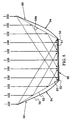
- FIG. 5 is a view similar to FIG. 4 which illustrates concentration of solar radiation upon the solar panel by the solar reflectors;
- FIG. 6 is a view similar to FIG. 4 which illustrates an interim position of the solar reflectors between the deployed position of FIG. 4 and a stowed position;
- FIG. 7 is an enlarged view of structure within the curved line 7 of FIG. 6 with an outer spring member of FIG. 6 shown in a stowed position;
- FIG. 8 is an enlarged view of inner portions of outer spring members of FIG. 3 which illustrates spring member movement between deployed and stowed positions;
- FIG. 9A is a rear view of adjacent solar panels of the solar wing of FIG. 2C which illustrates alternate stowed positions of outer spring members of FIG. 3;
- FIG. 9B illustrates the outer spring members of FIG. 9A when the solar panels are folded to the stowed configuration of FIG. 2A;
- FIG. 10 is an enlarged view of structure within the
curved line 10 of FIG. 3 which illustrates a rotatable coupling between a reflective sheet and an outer spring member of FIG. 3; - FIGS. 11A and 11B are enlarged views of an inner spring member of FIG. 3 which illustrates rotatable coupling embodiments between an inner spring member and a reflective sheet of FIG. 3; and
- FIG. 12 is an enlarged view of an inner portion of an outer spring member of FIG. 3 which illustrates another rotatable coupling embodiment between the outer spring member and the solar panel of FIG. 3.
-
- FIGS. 1-12 illustrate solar reflectors in which flexible, lightweight reflective sheets are positioned with inner and outer spring members which urge each sheet towards a planar configuration and further urge the sheet in a rotation away from a solar panel face. Restraint members limit this rotation to place the sheet in a deployed position in which it defines an angle with the panel to reflect solar radiation onto the panel face. The increased incident radiation permits a reduction of the number of solar cells with consequent savings in spacecraft cost and weight. In addition, the reflective sheets are stowed behind their associated solar panel so as not
- In particular, FIG. 1 illustrates a body-stabilized
spacecraft 20 which is traveling in anorbital plane 22 about a celestial body such as theEarth 24. The spacecraft's attitude can be described with reference to an orthogonal coordinatesystem 30 which has an origin at the spacecraft's center of mass. The coordinatesystem 30 includes ayaw axis 31 which is directed at theEarth 24, apitch axis 32 which is orthogonal to theorbital plane 22 and aroll axis 33 which is aligned with a velocity vector of thespacecraft 20. - The
spacecraft 20 has abody 34 which carries a pair ofsolar wings pitch axis 32 so that solar cells of the solar wings are as orthogonal as possible to aSun line 38 between a Sun (not shown) and thespacecraft 20. However, unless the solar wings can also be inclined from thepitch axis 32, they will be tilted from theSun line 38 at summer and winter solstice because the Earth travels in an orbital plane which is tilted from the Earth's equatorial plane. Typically, thespacecraft body 33 also carriesantennas thrusters - Each of the
solar wings solar panels 46 as shown in FIG. 2A. This figure also shows that thepanels 46 have been folded accordion fashion into a stowedconfiguration 48 adjacent to thespacecraft body 33. In FIG. 2B, thesolar panels 46 are shown in a rotation about inter-panel hinges 50 which extends them to the planar, deployedconfiguration 52 of FIG. 2C. - FIG. 1 shows pairs of
solar reflectors 60 of the present invention which are carried by thesolar wings solar reflectors 60 are also shown in the deployedconfiguration 52 of FIG. 2C. Although not specifically shown in FIGS. 2A and 2B, thesolar reflectors 60 rotate to stowed positions behind their respective solar panels prior to folding of the panels into the stowedconfiguration 48 of FIG. 2A. - The enlarged views of FIGS. 3 and 4 illustrate a single
solar panel 46 which extends laterally to apanel perimeter 55 and carries an array ofsolar cells 56 on apanel face 57. A pair ofsolar reflectors 60 is associated with thesolar panel 46 and each reflector includes areflective sheet 62 which has an inner part in the form of aninner margin 64 and an outer part in the form of anouter margin 66.Inner spring members 68 couple theinner margin 64 to thesolar panel 46 andouter spring members 70 couple theouter margin 66 to the solar panel (to more clearly show other structures, the inner spring members are omitted from FIG. 4). - The
inner spring members 68 are arranged to resiliently urge theinner margin 64 towards thesolar panel 46 and theouter spring members 70 are arranged to urge theouter margin 66 away from thesolar panel 46. In addition, theinner spring members 68 are coupled to different portions of the inner margin 64 (e.g., theopposed corners outer spring members 70 are coupled to different portions of the outer margin 66 (e.g., opposedcorners reflective sheet 62 towards a planar configuration. Accordingly, they achieve static equilibrium and accommodate thermal changes in the reflective sheet. - In the embodiment of FIGS. 3 and 4, each of the
inner spring members 68 is formed of a resilient, elongate member which is rotatably coupled to theperimeter 55 of thesolar panel 46 by a hinge 76 (to more clearly show other structures, the hinge is omitted from FIG. 4). When pulled by thereflective sheet 62 and theouter spring members 70 to a distorted state, theinner spring members 68 assume the bent configuration of FIG. 3 in which they urge theopposed corners solar panel 46. - In the embodiment of FIGS. 3 and 4, each of the
outer spring members 66 is also formed of a resilient, elongate member which is rotatably coupled to the solar panel'sperimeter 74. This rotatable coupling can be accomplished with various structures such as thehinge 80 of FIG. 3 (to more clearly show other structures, the hinge is omitted from FIG. 4) or a cord which is described below with reference to FIG. 10. Astop 82 is arranged so that it angularly restrains an inner portion of theouter spring member 70. This inner portion is accordingly directed along abroken direction line 88. - Each
solar reflector 60 also includes restraint members in the form oftethers 90 which are formed, for example, of flexible cord and are connected between the outer margin 66 (e.g., theopposed corners 73 and 74) and the opposite side of the solar panel'sperimeter 55. Because of opposition between the restraining action of thetethers 90 and the abutting action of thestop 82, eachouter spring member 70 is pulled to a distorted state and assumes the bent configuration of FIGS. 3 and 4. In this configuration, theouter spring members 70 urge theopposed corners solar panel 46. - The resilient
outer spring members 70 try to move to a relaxed linear state and, in so doing, they urge thereflective sheet 62 along a rotation away from thepanel face 57. This rotation is limited by thetethers 90 so that thereflective sheet 62 is restrained in the deployed position of FIGS. 3 and 4. In this deployed position, thereflective sheet 62 defines a deployedangle 92 with thesolar panel 46 and arestrained angle 93 with the direction line 88 (angles angle 92 is sufficient to cause thereflective sheet 62 to reflect radiation onto thepanel face 57. The length of thetether 90 and the angle set by thestop 82 force theouter spring member 70 to a desired deployed angle. The stop acts to urge thereflective sheet 62 towards a stowed position while the tether acts to restrain thereflective sheet 62 in a deployed position. These actions resiliently balance out. - Together, the
inner spring members 68, theouter spring members 70 and therestraint members 90form deployment structures 94 which position thereflective sheets 62 so that they concentrate solar radiation onto thesolar panels 46. In particular, theinner spring members 68 hold theinner margin 64 and thereby balance the static forces which hold eachreflective sheet 62 in the desired reflective position. - Operational concentration of solar radiation is illustrated in FIG. 5 which is a view similar to FIG. 4 with like elements represented by like reference numbers. In a central region of FIG. 5,
solar radiation 100 falls directly onto thepanel face 57 of thesolar panel 46. In outer regions of FIG. 5,solar radiation 102 which would otherwise pass by thesolar panel 46 is reflected from thereflective sheets 60 to be incident onto thepanel face 57. - Solar cell conversion efficiency of incident solar radiation into electrical energy is a function of the angle of incidence and generally falls off with lesser angle of incidence. Accordingly, the
radiation 102 that is reflected onto thepanel face 57 by thesolar reflectors 60 is converted into energy at a lower efficiency than thesolar radiation 100 which is directly incident (a greater effect on conversion efficiency of all incident radiation is caused by the increased heating of the solar cells). Nonetheless, the output power from the solar cells of thesolar panel 46 is significantly enhanced by addition of the redirectedradiation 102. Accordingly, thesolar reflectors 60 facilitate a reduction in the number of solar cells required for a given spacecraft power drain. - FIG. 4 is an end view of the
solar reflectors 60 in their deployed position. From this state, the reflectors are easily rotated to a stowed position behind their associatedsolar panel 46 as illustrated in FIGS. 6 and 7. Theouter spring members 70 are manually rotated away from thepanel face 57 and towards the solar panel back face 106 (thehinges 80 are omitted in FIG. 6 to to more clearly show other structures). Each of thetethers 90 is received at thepanel perimeter 55 into atether guide 110. - Preferably, each
guide 110 has a U-shaped cross section so that its tether is restrained laterally (as shown in FIG. 7 by a broken line path 112) and does not slip out of the guide. Because of the restraining action of the tether, the outer end of theouter spring member 70 is pulled closer to thehinge 76 as it rotates towards theback face 106. Consequently, the distortion of theouter spring member 70 is increased which provides a stored energy to deploy the solar reflector (60 in FIG. 3). To accommodate the decreased distance between the ends of the outer spring member, thereflective sheets 62 are folded as shown in FIG. 6. - In FIG. 7, an
outer spring member 70 has reached its stowed position adjacent the panel backsurface 106. A rotation point is established (e.g., by the hinge 80) about which theouter spring member 70 rotates as it moves between its stowed position and its deployed position (of FIGS. 3-5). Theguide 110 is configured to form apath 112 so that at least some part of this path is spaced (e.g., by a space 114) from the rotation point of thehinge 80. In the embodiment of FIG. 7, theguide 110 forms anarcuate path 112 so that as thetether 90 is guided along theguide path 112, it is spaced at all parts of this path from the rotation point of thehinge 80. - Because of the
space 114, a portion of the urging force of the distortedouter spring member 70 against the restraint of thetether 90 contains a downward vector component which initializes a rotational movement of theouter spring member 70 from its stowed position of FIG. 7 to its deployed position of FIGS. 3-5 (i.e., the spacing facilitates automatic rotation of said outer spring member from its stowed position to its deployed position). Theguide 110 and itspath 112 causes a mechanical moment (i.e., a torque) to be generated in theouter spring member 70 which urges it away from its stowed position. Although theguide 110 is configured in FIG. 7 to form anacurate guide path 112, other paths can also generate the needed mechanical moment. - Accordingly, as the
solar panels 46 deploy from their stowed arrangement of FIG. 2A to their deployed configuration of FIG. 2C, their respective solar reflectors rotate from their back faces to the deployed position of FIG. 2C. Preferably, this rotation is delayed to insure that it does not interfere with the accordion movement of thesolar panels 46 about their hinges 50. This delay can be accomplished by capturing eachouter spring member 70 to itsrespective panel 46 with a releasable restraint (e.g., a mechanical latch or an explosive bolt). Once thepanels 46 are safely deployed to the deployed configuration of FIG. 2C, the restraints can be released and the outer spring members automatically move to their deployed position of FIG. 2C. - The movement of the
outer spring members 70 between their deployed and stowed positions is further enhanced by providing their inner end with a rotatable attachment as shown in FIG. 8. Extending outward from the hinge 80 (beneath the stop 82) is ahinge leaf 116 which rotatably carries theinner end 118 of the outer spring members 70 (e.g., by means of a pin 120). Theinner end 118 can thus rotate between a deployedposition 118A and either of two stowedpositions position 118B, theend 118 is directed away from the panel mid-region. In the stowedposition 118C, theend 118 is directed upward along the panel mid-region. The stowedpositions outer spring members 70 to lie parallel to the panel back face 106 when in the stowed position of FIG. 7. - The stowed
positions outer spring members 70 to better use the limited space between the back faces of adjacentsolar panels 46. For example, FIG. 9A shows theback surfaces 106 ofadjacent panels respective hinge leaf 116. One set ofouter spring members 70 is stowed with theirinner ends 118 in the stowedposition 118B and the other set is stowed with theirinner ends 118 in the stowedposition 118C. This arrangement is reversed in the adjacentsolar panel 46B. - As a consequence, the outer spring members only overlap at discrete crossover points when the panels are in the stowed configuration of FIG. 2A as shown in FIG. 9B (for clarity, the
panel 46A is assumed to be transparent in this view). As a result, the outer spring members can be more easily accommodated into the space between the back faces of the adjacentsolar panels outer spring members 70 at the crossover points, the members can carry soft, resilient collars 119 (e.g., of foam rubber) as shown at an exemplary crossover point in FIG. 9A. - The outer ends of the
outer spring members 70 are preferably rotatably coupled to their respectivereflective sheet 62 to facilitate free movement of the sheet. This rotatable coupling can be realized, for example, with aflexible cord 121 that is received through ahole 122 in anouter end 123 of theouter spring member 70 and ahole 124 near theouter margin 66 of thereflective sheet 62 as shown in FIG. 10. This outer spring member'stether 90 can also be received through thehole 122. Other exemplary rotatable couplings can be formed by receiving theouter end 123 into a cup that is carried by thesheet corner 74 and formed with a ball and socket structure that is shared between theouter end 123 and thesheet corner 74. Preferably, thesheet corner 74 is strengthened by adoubler 125 that is indicated by a broken line. In addition, all edges of thesheet 62 may be strengthened by formation of similar doubler structures. - The outer ends of the
inner spring members 68 are also preferably rotatably coupled to their respectivereflective sheet 62 to facilitate free movement of the sheet. This rotatable coupling can be realized, as shown in FIG. 11A, with aflexible cord 127 that is received through ahole 128 near theinner margin 64 of thesheet 62 and received through anannular sleeve 129 that slides on theinner spring member 68.Stops 130 on the inner spring member limit the travel of thesleeve 129. - FIG. 11 B is similar to FIG. 11A with like elements indicated by like reference numbers. This figure illustrates another rotatable coupling embodiment in which the
inner spring member 68 is received through a doubled portion of theinner margin 64. The portion forms achannel 132 through which theinner spring member 68 is slidingly received. - Although FIGS. 10, 11A and 11B have illustrated
holes reflective sheet 62, many other attachment structures may be used. In an exemplary one, the thin-film sheet is reinforced near its corners with extra sheet portions to form a doubler. Cords such as thecords outer spring members - FIG. 7 illustrates that the
stop 82 has a slopedface 134 which establishes theinitial direction 88 of the inner end of theouter spring members 70 as indicated in FIG. 4. In addition, FIGS. 7 and 8 show rotatable couplings for the inner ends 118 of theouter spring members 70. Another embodiment of these structures is illustrated in FIG. 12 in which theinner end 118 of theouter spring member 70 is rotatably coupled to thesolar panel 46 by acord 136 which attaches to abracket 138 at thepanel perimeter 55. Theupper leg 140 of thebracket 138 extends outward to form astop 140 which abuts theinner end 118 of theouter spring member 70. This abutment sets the initial direction of the inner end (i.e., thedirection 88 of FIG. 4). - The solar reflectors of FIGS. 1-12 can be realized with a variety of materials. In an exemplary realization, the
reflective sheets 62 are formed of a lightweight, flexible thin-film polymer (e.g., polyimide or polyester in a thickness between 10 and 80 micrometers). To enhance the reflection of solar radiation (102 in FIG. 5), thesheet 62 preferably carries areflective coating 144 of a metal (e.g., aluminum or silver deposited by vapor deposition) on its inner face as indicated locally in FIG. 5. The sheet material may be specular or diffused (e.g., via wrinkles, embossing, brushing and the like) for an optimal power output in various configurations (e.g., panel, wing and pointing configurations). -
Large sheets 62 will typically accumulate a significant electrostatic charge which may cause damage to spacecraft electrical components (e.g., the solar cells 56). This charge can be safely dissipated if a path exists to conductive portions of the solar panels 46 (solar panels are typically formed of conductive materials that connect to an electrical ground). Preferably, therefore, the inner andouter spring members tethers 62 form conductive paths from their associated reflective sheet. In an exemplary realization of these elements, therefore, the inner andouter spring members tethers 80 are formed of metal-impregnated, polyamide fibers. - Another embodiment of the
inner spring members 68 is formed by a conductivehelical spring 146 as indicated in FIG. 3. One end of the spring is attached to acorner 72 of the reflective sheet. In order to urge thecorner 72 towards thesolar panel 46 and away from opposite corners of the inner andouter margins interpanel hinge 50 and terminated on an adjacentsolar panel 46A. Still other embodiments of theinner spring member 68 can be formed with various resilient structures (e.g., leaf springs). - The teachings of the invention can be practiced with various dimensional and geometrical variations of reflector structures. In an exemplary solar reflector of the invention, the
deployment angle 92 is substantially 120 degrees and thewidth 152 of thereflective sheets 62 is 1.1 times thewidth 154 of the solar panel 46 (the deployment angle and the widths are shown in FIG. 4). - It has been calculated that this arrangement will increase the incident radiation on the
panel face 57 by a factor greater than 2. It has been further calculated that this concentration factor is typically reduced to the range of 1.7 to 1.9 when pointing errors, reflector flatness, reflector specularity, reflector reflectivity and reflector defects are taken into account. It is estimated that this arrangement of a pair of solar reflectors (60 in FIG. 3) for a solar panel having approximately a 200 centimeter width and a 350 centimeter length will have a weight of approximately 2 kilograms. - Although embodiments of the invention have been illustrated with pairs of reflective sheets, inner spring members, outer spring members and tethers, the concepts and teachings of the invention can be followed to adapt single members of these structures so as to reflect solar radiation onto solar cells. To provide for spacecraft attitude errors, it may be desirable to extend the outer margin of the reflective sheets further from their respective solar panels than shown, for example, in FIG. 5. This extension will compensate for the attitude errors so that the solar panels continue to be fully covered with reflected
radiation 102. - Although the inner and
outer spring members reflective sheets 62, the invention generally teaches coupling to any inner and outer parts of the sheets. In other embodiments of the invention, the coupling of the inner and outer spring members to a solar panel may be facilitated with other structures, e.g., a third member that is rotatably carried by the solar panel. - While several illustrative embodiments of the invention have been shown and described, numerous variations and alternate embodiments will occur to those skilled in the art. Such variations and alternate embodiments are contemplated, and can be made without departing from the spirit and scope of the invention as defined in the appended claims.
Claims (10)
- A solar reflector for concentrating solar radiation upon a panel face of a solar panel which extends to a panel perimeter, characterized by:at least one flexible, reflective sheet (62) having an inner part (64) and an outer part (66);at least one inner spring member (68) coupling said inner part (64) to said panel (46) and arranged to urge said inner part (64) towards said panel (46);at least one outer spring member (70) coupling said outer part (66) to said panel (46) and arranged to urge said outer part (66) away from said panel (46) so that said inner and outer spring members (68, 70) cooperatively urge said reflective sheet (62) towards a planar configuration, said outer spring member (70) further arranged to urge said reflective sheet (62) along a rotation away from said panel face (46); andat least one restraint member (90) arranged to limit said rotation so that said reflective sheet (62) is restrained in a deployed position in which it defines an angle (92, 93) with said panel to reflect solar radiation onto said panel face.
- The solar reflector of claim 1, characterized in that said inner and outer spring members (68, 70) are resilient, electrically-conductive, elongate members which form conduction paths away from said reflective sheet (62).
- The solar reflector of claim 1 or 2, characterized in that said restraint member (90) is an electrically-conductive tether which forms a conduction path away from said reflective sheet (62).
- The solar reflector of any of claims 1 through 3, characterized in that said outer spring member includes an inner portion which is rotatably coupled to said panel (46) and further including a stop (82) carried by said panel to abut said inner portion and facilitate the urging of said reflective sheet (62) by said outer spring member (70) that results in said rotation.
- The solar reflector of any of claims 1 through 4, characterized in thatsaid restraint member (90) is a tether;said outer spring member (70) rotates about a rotation point (80); anda guide (110) is provided, which is positioned in the region of said panel perimeter (55) to receive said tether (90) when said outer spring member (70) is in said stowed position, said guide (110) being configured to guide said tether (90) along a guide path (112) which is spaced from said rotation point (80) to facilitate the rotation of said outer spring member (70) from a stowed position behind said panel (46) to said deployed position.
- A solar reflector for concentrating solar radiation upon a panel face (57) of a solar panel (46) which extends to a panel perimeter (55), characterized by:first and second flexible, reflective sheets (62), each of said reflective sheets having an inner margin (64) and an outer margin (66); andfirst and second deployment structures (94) respectively coupling said first and second reflective sheets to said panel; wherein each of said deployment structures includes:a) first and second inner spring members (68) coupling first and second portions of the inner margin (64) of a respective one of said reflective sheets (62) to said panel (46), said first and second inner spring members (68) arranged to urge said first and second inner margin portions (64) away from each other and to urge said inner margin (64) towards said panel (46);b) first and second outer spring members (70) coupling first and second portions of the outer margin (66) of said respective reflective sheet (62) to said panel (46), said first and second inner spring members (68) arranged to urge said first and second outer margin portions (66) away from each other and to urge said outer margin (66) away from said panel (46) so that said inner and outer spring members (69, 70) cooperatively urge said respective reflective sheet (62) towards a planar configuration, said outer spring members (70) further arranged to urge said respective reflective sheet in a rotation away from said panel face (57); andc) first and second restraint members (90) coupled between said outer margin (66) of said respective reflective sheet (62) and said panel (46) to limit said rotation so that said respective reflective sheet (62) is restrained in a deployed position in which it defines an angle with said respective panel to reflect solar radiation onto said panel face (57).
- A method of concentrating solar radiation upon a panel face (57) of a solar panel (46), comprising the steps of:urging a flexible, reflective sheet (62) towards a planar configuration;urging said reflective sheet (62) along a rotation away from said panel face (57); andlimiting said rotation so that said reflective sheet (62) is in a deployed position in which it defines an angle with said panel to reflect solar radiation upon said panel face (57).
- The method of claim 7, characterized in that said urging steps include the step of moving said reflective sheet (62) with resilient, elongate members (68, 70).
- The method of claim 7 or 8, further including the step of conducting electrical charges away from said reflective sheet (62).
- A spacecraft system, comprising:a spacecraft (20);at least one solar panel (46) carried by said spacecraft to convert solar radiation into electrical power, anda reflector (60) arranged to concentrate said solar radiation onto said solar panel, characterized in that said reflector comprises:a) at least one flexible, reflective sheet (62) having an inner part (64) and an outer part (66);b) at least one inner spring member (68) coupling said inner part (64) to said panel (46) and arranged to urge said inner part (64) towards said panel (46);c) at least one outer spring member (70) coupling said outer part (66) to said panel (46) and arranged to urge said outer part (66) away from said panel so that said inner and outer spring members (68, 70) cooperate to urge said reflective sheet (62) towards a planar configuration, said outer spring member (70) further arranged to urge said reflective sheet (62) in a rotation away from said panel face (57); andd) at least one restraint member (90) arranged to limit said rotation so that said reflective sheet (62) is restrained in a deployed position in which it defines an angle with said panel (46) to reflect solar radiation (100, 102) upon said panel face (57).
Priority Applications (2)
| Application Number | Priority Date | Filing Date | Title |
|---|---|---|---|
| DE69831662T DE69831662T2 (en) | 1998-07-30 | 1998-07-30 | Mirror foils for concentrator solar panels |
| EP98114321A EP0976655B1 (en) | 1998-07-30 | 1998-07-30 | Thin-film reflectors for concentration solar array |
Applications Claiming Priority (1)
| Application Number | Priority Date | Filing Date | Title |
|---|---|---|---|
| EP98114321A EP0976655B1 (en) | 1998-07-30 | 1998-07-30 | Thin-film reflectors for concentration solar array |
Publications (2)
| Publication Number | Publication Date |
|---|---|
| EP0976655A1 true EP0976655A1 (en) | 2000-02-02 |
| EP0976655B1 EP0976655B1 (en) | 2005-09-21 |
Family
ID=8232375
Family Applications (1)
| Application Number | Title | Priority Date | Filing Date |
|---|---|---|---|
| EP98114321A Expired - Lifetime EP0976655B1 (en) | 1998-07-30 | 1998-07-30 | Thin-film reflectors for concentration solar array |
Country Status (2)
| Country | Link |
|---|---|
| EP (1) | EP0976655B1 (en) |
| DE (1) | DE69831662T2 (en) |
Cited By (7)
| Publication number | Priority date | Publication date | Assignee | Title |
|---|---|---|---|---|
| EP1408557A1 (en) * | 2002-10-10 | 2004-04-14 | Alcatel | Solar generator panel and spacecraft with such panel |
| EP1422763A1 (en) * | 2002-11-25 | 2004-05-26 | Alcatel | Solar cell for solar generator panel, solar generator panel and spacecraft |
| CN100444411C (en) * | 2007-01-31 | 2008-12-17 | 黄上立 | Spinned deployable thin film solar battery array and its application in space |
| US10340698B2 (en) | 2014-05-14 | 2019-07-02 | California Institute Of Technology | Large-scale space-based solar power station: packaging, deployment and stabilization of lightweight structures |
| US10454565B2 (en) | 2015-08-10 | 2019-10-22 | California Institute Of Technology | Systems and methods for performing shape estimation using sun sensors in large-scale space-based solar power stations |
| EP3742603A4 (en) * | 2018-01-16 | 2021-06-02 | Sung Chang Co., Ltd | Solar module installation method for efficient use of sunlight |
| CN113630084A (en) * | 2021-10-12 | 2021-11-09 | 南通睿博电器有限公司 | Photovoltaic module |
Families Citing this family (6)
| Publication number | Priority date | Publication date | Assignee | Title |
|---|---|---|---|---|
| US11128179B2 (en) | 2014-05-14 | 2021-09-21 | California Institute Of Technology | Large-scale space-based solar power station: power transmission using steerable beams |
| JP6640116B2 (en) | 2014-06-02 | 2020-02-05 | カリフォルニア インスティチュート オブ テクノロジー | Large Space Solar Power Plants: Efficient Power Generation Tiles |
| EP3325347B1 (en) | 2015-07-22 | 2021-06-16 | California Institute of Technology | Large-area structures for compact packaging |
| US10992253B2 (en) | 2015-08-10 | 2021-04-27 | California Institute Of Technology | Compactable power generation arrays |
| US11634240B2 (en) | 2018-07-17 | 2023-04-25 | California Institute Of Technology | Coilable thin-walled longerons and coilable structures implementing longerons and methods for their manufacture and coiling |
| US11772826B2 (en) | 2018-10-31 | 2023-10-03 | California Institute Of Technology | Actively controlled spacecraft deployment mechanism |
Citations (6)
| Publication number | Priority date | Publication date | Assignee | Title |
|---|---|---|---|---|
| DE1764428A1 (en) * | 1968-06-04 | 1971-07-22 | Telefunken Patent | Arrangement for converting radiation energy into electrical energy from radiation-sensitive components, in particular solar cell batteries |
| US4284394A (en) | 1980-09-19 | 1981-08-18 | United Technologies Corporation | Gas manifold for particle quenching |
| JPH04146897A (en) * | 1990-10-09 | 1992-05-20 | Nec Corp | Flexible solar battery array |
| JPH05116692A (en) * | 1991-10-30 | 1993-05-14 | Nec Eng Ltd | Solar paddle for artificial satellite |
| US5520747A (en) * | 1994-05-02 | 1996-05-28 | Astro Aerospace Corporation | Foldable low concentration solar array |
| US8190993B2 (en) | 1999-08-31 | 2012-05-29 | Sony Corporation | Menu selection using a rotating dial and button |
-
1998
- 1998-07-30 DE DE69831662T patent/DE69831662T2/en not_active Expired - Lifetime
- 1998-07-30 EP EP98114321A patent/EP0976655B1/en not_active Expired - Lifetime
Patent Citations (6)
| Publication number | Priority date | Publication date | Assignee | Title |
|---|---|---|---|---|
| DE1764428A1 (en) * | 1968-06-04 | 1971-07-22 | Telefunken Patent | Arrangement for converting radiation energy into electrical energy from radiation-sensitive components, in particular solar cell batteries |
| US4284394A (en) | 1980-09-19 | 1981-08-18 | United Technologies Corporation | Gas manifold for particle quenching |
| JPH04146897A (en) * | 1990-10-09 | 1992-05-20 | Nec Corp | Flexible solar battery array |
| JPH05116692A (en) * | 1991-10-30 | 1993-05-14 | Nec Eng Ltd | Solar paddle for artificial satellite |
| US5520747A (en) * | 1994-05-02 | 1996-05-28 | Astro Aerospace Corporation | Foldable low concentration solar array |
| US8190993B2 (en) | 1999-08-31 | 2012-05-29 | Sony Corporation | Menu selection using a rotating dial and button |
Non-Patent Citations (2)
| Title |
|---|
| PATENT ABSTRACTS OF JAPAN vol. 016, no. 428 (M - 1307) 8 September 1992 (1992-09-08) * |
| PATENT ABSTRACTS OF JAPAN vol. 017, no. 483 (M - 1472) 2 September 1993 (1993-09-02) * |
Cited By (12)
| Publication number | Priority date | Publication date | Assignee | Title |
|---|---|---|---|---|
| EP1408557A1 (en) * | 2002-10-10 | 2004-04-14 | Alcatel | Solar generator panel and spacecraft with such panel |
| FR2845822A1 (en) * | 2002-10-10 | 2004-04-16 | Cit Alcatel | SOLAR GENERATOR PANEL AND SPACE VEHICLE COMPRISING SUCH A PANEL |
| US7321095B2 (en) | 2002-10-10 | 2008-01-22 | Thales | Solar generator panel and a spacecraft including it |
| EP1422763A1 (en) * | 2002-11-25 | 2004-05-26 | Alcatel | Solar cell for solar generator panel, solar generator panel and spacecraft |
| FR2847719A1 (en) * | 2002-11-25 | 2004-05-28 | Cit Alcatel | SOLAR CELL FOR SOLAR GENERATOR PANEL, SOLAR GENERATOR PANEL, AND SPACE VEHICLE |
| US7368656B2 (en) | 2002-11-25 | 2008-05-06 | Thales | Solar cell for a solar generator panel, a solar generator panel, and a space vehicle |
| CN100444411C (en) * | 2007-01-31 | 2008-12-17 | 黄上立 | Spinned deployable thin film solar battery array and its application in space |
| US10340698B2 (en) | 2014-05-14 | 2019-07-02 | California Institute Of Technology | Large-scale space-based solar power station: packaging, deployment and stabilization of lightweight structures |
| US10454565B2 (en) | 2015-08-10 | 2019-10-22 | California Institute Of Technology | Systems and methods for performing shape estimation using sun sensors in large-scale space-based solar power stations |
| EP3742603A4 (en) * | 2018-01-16 | 2021-06-02 | Sung Chang Co., Ltd | Solar module installation method for efficient use of sunlight |
| CN113630084A (en) * | 2021-10-12 | 2021-11-09 | 南通睿博电器有限公司 | Photovoltaic module |
| CN113630084B (en) * | 2021-10-12 | 2021-12-10 | 南通睿博电器有限公司 | Photovoltaic module |
Also Published As
| Publication number | Publication date |
|---|---|
| DE69831662T2 (en) | 2006-07-06 |
| EP0976655B1 (en) | 2005-09-21 |
| DE69831662D1 (en) | 2006-02-02 |
Similar Documents
| Publication | Publication Date | Title |
|---|---|---|
| US6017002A (en) | Thin-film solar reflectors deployable from an edge-stowed configuration | |
| US6050526A (en) | Solar reflector systems and methods | |
| US4282394A (en) | Underwing reflector solar array | |
| EP0976655B1 (en) | Thin-film reflectors for concentration solar array | |
| EP0754625B1 (en) | Hybrid solar panel array | |
| US6119986A (en) | Thin-film solar reflectors and methods | |
| US5520747A (en) | Foldable low concentration solar array | |
| US10340843B2 (en) | Solar panel with flexible optical elements | |
| US6655638B2 (en) | Solar array concentrator system and method | |
| US6102339A (en) | Sun-synchronous sun ray blocking device for use in a spacecraft having a directionally controlled main body | |
| US8066227B2 (en) | Deployable structures having collapsible structural members | |
| US6437232B1 (en) | D-wing deployable solar array | |
| EP1807870B1 (en) | Solar concentrator | |
| US6188012B1 (en) | Methods and systems for a solar cell concentrator | |
| US5720452A (en) | Solar panel parallel mounting configuration | |
| NL2016677B1 (en) | Solar Panel and Flexible Radiator for a Spacecraft. | |
| US6031178A (en) | System to link the kinematics of neighboring panels in a panel assembly | |
| US4787580A (en) | Large solar arrays with high natural frequencies | |
| EP0977273A1 (en) | Solar reflector systems and methods | |
| US5618012A (en) | Satellite stabilization system | |
| CN1341536A (en) | Spin-stabilized film reflector and its application in space | |
| RU2002682C1 (en) | Space vehicle |
Legal Events
| Date | Code | Title | Description |
|---|---|---|---|
| PUAI | Public reference made under article 153(3) epc to a published international application that has entered the european phase |
Free format text: ORIGINAL CODE: 0009012 |
|
| AK | Designated contracting states |
Kind code of ref document: A1 Designated state(s): DE FR GB |
|
| AX | Request for extension of the european patent |
Free format text: AL;LT;LV;MK;RO;SI |
|
| 17P | Request for examination filed |
Effective date: 20000720 |
|
| AKX | Designation fees paid |
Free format text: DE FR GB |
|
| 17Q | First examination report despatched |
Effective date: 20021126 |
|
| GRAP | Despatch of communication of intention to grant a patent |
Free format text: ORIGINAL CODE: EPIDOSNIGR1 |
|
| GRAS | Grant fee paid |
Free format text: ORIGINAL CODE: EPIDOSNIGR3 |
|
| GRAA | (expected) grant |
Free format text: ORIGINAL CODE: 0009210 |
|
| AK | Designated contracting states |
Kind code of ref document: B1 Designated state(s): DE FR GB |
|
| REG | Reference to a national code |
Ref country code: GB Ref legal event code: FG4D |
|
| REF | Corresponds to: |
Ref document number: 69831662 Country of ref document: DE Date of ref document: 20051027 Kind code of ref document: P |
|
| REF | Corresponds to: |
Ref document number: 69831662 Country of ref document: DE Date of ref document: 20060202 Kind code of ref document: P |
|
| ET | Fr: translation filed | ||
| PLBE | No opposition filed within time limit |
Free format text: ORIGINAL CODE: 0009261 |
|
| STAA | Information on the status of an ep patent application or granted ep patent |
Free format text: STATUS: NO OPPOSITION FILED WITHIN TIME LIMIT |
|
| 26N | No opposition filed |
Effective date: 20060622 |
|
| REG | Reference to a national code |
Ref country code: FR Ref legal event code: PLFP Year of fee payment: 19 |
|
| PGFP | Annual fee paid to national office [announced via postgrant information from national office to epo] |
Ref country code: GB Payment date: 20160727 Year of fee payment: 19 Ref country code: DE Payment date: 20160726 Year of fee payment: 19 |
|
| PGFP | Annual fee paid to national office [announced via postgrant information from national office to epo] |
Ref country code: FR Payment date: 20160726 Year of fee payment: 19 |
|
| REG | Reference to a national code |
Ref country code: DE Ref legal event code: R119 Ref document number: 69831662 Country of ref document: DE |
|
| GBPC | Gb: european patent ceased through non-payment of renewal fee |
Effective date: 20170730 |
|
| REG | Reference to a national code |
Ref country code: FR Ref legal event code: ST Effective date: 20180330 |
|
| PG25 | Lapsed in a contracting state [announced via postgrant information from national office to epo] |
Ref country code: GB Free format text: LAPSE BECAUSE OF NON-PAYMENT OF DUE FEES Effective date: 20170730 Ref country code: DE Free format text: LAPSE BECAUSE OF NON-PAYMENT OF DUE FEES Effective date: 20180201 |
|
| PG25 | Lapsed in a contracting state [announced via postgrant information from national office to epo] |
Ref country code: FR Free format text: LAPSE BECAUSE OF NON-PAYMENT OF DUE FEES Effective date: 20170731 |