EP0969351A2 - Information processing apparatus - Google Patents
Information processing apparatus Download PDFInfo
- Publication number
- EP0969351A2 EP0969351A2 EP99304980A EP99304980A EP0969351A2 EP 0969351 A2 EP0969351 A2 EP 0969351A2 EP 99304980 A EP99304980 A EP 99304980A EP 99304980 A EP99304980 A EP 99304980A EP 0969351 A2 EP0969351 A2 EP 0969351A2
- Authority
- EP
- European Patent Office
- Prior art keywords
- keyboard
- board
- post
- display part
- information processing
- Prior art date
- Legal status (The legal status is an assumption and is not a legal conclusion. Google has not performed a legal analysis and makes no representation as to the accuracy of the status listed.)
- Ceased
Links
- 230000010365 information processing Effects 0.000 title claims abstract description 12
- 230000006870 function Effects 0.000 description 6
- 230000007257 malfunction Effects 0.000 description 4
- 238000000034 method Methods 0.000 description 4
- 238000004891 communication Methods 0.000 description 3
- 230000001419 dependent effect Effects 0.000 description 2
- 230000000717 retained effect Effects 0.000 description 2
- 238000010586 diagram Methods 0.000 description 1
- 238000006073 displacement reaction Methods 0.000 description 1
- 238000005516 engineering process Methods 0.000 description 1
- 238000005286 illumination Methods 0.000 description 1
- 239000004973 liquid crystal related substance Substances 0.000 description 1
- 235000015250 liver sausages Nutrition 0.000 description 1
- 230000002093 peripheral effect Effects 0.000 description 1
- 230000005236 sound signal Effects 0.000 description 1
Images


Classifications
-
- G—PHYSICS
- G06—COMPUTING; CALCULATING OR COUNTING
- G06F—ELECTRIC DIGITAL DATA PROCESSING
- G06F1/00—Details not covered by groups G06F3/00 - G06F13/00 and G06F21/00
- G06F1/16—Constructional details or arrangements
-
- G—PHYSICS
- G06—COMPUTING; CALCULATING OR COUNTING
- G06F—ELECTRIC DIGITAL DATA PROCESSING
- G06F1/00—Details not covered by groups G06F3/00 - G06F13/00 and G06F21/00
- G06F1/16—Constructional details or arrangements
- G06F1/1613—Constructional details or arrangements for portable computers
- G06F1/1633—Constructional details or arrangements of portable computers not specific to the type of enclosures covered by groups G06F1/1615 - G06F1/1626
- G06F1/1684—Constructional details or arrangements related to integrated I/O peripherals not covered by groups G06F1/1635 - G06F1/1675
- G06F1/1686—Constructional details or arrangements related to integrated I/O peripherals not covered by groups G06F1/1635 - G06F1/1675 the I/O peripheral being an integrated camera
-
- G—PHYSICS
- G06—COMPUTING; CALCULATING OR COUNTING
- G06F—ELECTRIC DIGITAL DATA PROCESSING
- G06F1/00—Details not covered by groups G06F3/00 - G06F13/00 and G06F21/00
- G06F1/16—Constructional details or arrangements
- G06F1/1613—Constructional details or arrangements for portable computers
- G06F1/1615—Constructional details or arrangements for portable computers with several enclosures having relative motions, each enclosure supporting at least one I/O or computing function
- G06F1/1616—Constructional details or arrangements for portable computers with several enclosures having relative motions, each enclosure supporting at least one I/O or computing function with folding flat displays, e.g. laptop computers or notebooks having a clamshell configuration, with body parts pivoting to an open position around an axis parallel to the plane they define in closed position
-
- G—PHYSICS
- G06—COMPUTING; CALCULATING OR COUNTING
- G06F—ELECTRIC DIGITAL DATA PROCESSING
- G06F1/00—Details not covered by groups G06F3/00 - G06F13/00 and G06F21/00
- G06F1/16—Constructional details or arrangements
- G06F1/1613—Constructional details or arrangements for portable computers
- G06F1/1633—Constructional details or arrangements of portable computers not specific to the type of enclosures covered by groups G06F1/1615 - G06F1/1626
- G06F1/1675—Miscellaneous details related to the relative movement between the different enclosures or enclosure parts
- G06F1/1679—Miscellaneous details related to the relative movement between the different enclosures or enclosure parts for locking or maintaining the movable parts of the enclosure in a fixed position, e.g. latching mechanism at the edge of the display in a laptop or for the screen protective cover of a PDA
-
- G—PHYSICS
- G06—COMPUTING; CALCULATING OR COUNTING
- G06F—ELECTRIC DIGITAL DATA PROCESSING
- G06F1/00—Details not covered by groups G06F3/00 - G06F13/00 and G06F21/00
- G06F1/16—Constructional details or arrangements
- G06F1/1613—Constructional details or arrangements for portable computers
- G06F1/1633—Constructional details or arrangements of portable computers not specific to the type of enclosures covered by groups G06F1/1615 - G06F1/1626
- G06F1/1684—Constructional details or arrangements related to integrated I/O peripherals not covered by groups G06F1/1635 - G06F1/1675
- G06F1/169—Constructional details or arrangements related to integrated I/O peripherals not covered by groups G06F1/1635 - G06F1/1675 the I/O peripheral being an integrated pointing device, e.g. trackball in the palm rest area, mini-joystick integrated between keyboard keys, touch pads or touch stripes
Definitions
- the present invention relates generally to an information processing apparatus, for example a portable computer. More particularly, the invention relates to a structure for attaching to such a computer a pointing member (called the pointing device hereunder) that incorporates a strain gage to move a displayed cursor on a display part.
- a pointing member called the pointing device hereunder
- portable computers illustratively comprise a body and a display part each.
- the display part is attached swingingly to the body.
- the face of the body comprises a keyboard used to input characters, symbols, etc.
- An LCD for displaying images entered through the keyboard is attached to the display part.
- the keyboard is equipped with a pointing device incorporating a strain gage, the pointing device being used to move a displayed cursor on the display part.
- Fig. 13 shows a conventional structure for attaching a pointing device 101 to a keyboard 4.
- the pointing device 101 has a cross-shaped strain gage 103 formed by thick-film technology on a rectangular PC board 102.
- a rectangular prism post 104 is erected perpendicularly at the center of the strain gage 103.
- the pointing device 101 is fitted to the keyboard 4 as follows: the post 104 is first inserted into a through-hole 4a formed approximately in the middle of the keyboard 4.
- the board 102 is placed snugly onto the back of the keyboard 4. With the board 102 pushed against the back of the keyboard 4 using a holding plate 105, the holding plate 105 is fastened to the keyboard 4 by means of four screws 106. More specifically, the screws 106 are placed into holes 105a formed near the four corners of the holding pate 105. The screws 106 are then screwed into blind tapped holes, not shown, in the back of the keyboard 4.
- attaching holes 4b are formed in the keyboard 4, as shown in Fig. 14.
- the four screws 106, inserted into the attaching holes 4b, are screwed into the holes 105b near the four corners of the holding plate 105.
- the holding plate 105 is needed in order to fasten the board 102 onto the back of the keyboard 4.
- the structure is thus bound to increase the number of components as well as the number of assembling steps, thus incurring cost increases. Pushing the pointing device 101 against the back of the keyboard 4 by means of the holding plate 105 generates strain and can lead to malfunctions.
- an information processing apparatus comprising: a keyboard for inputting signals; a display part for displaying the signals input through the keyboard; and a pointing member attached to the keyboard and having a board, a strain gage and a post, the strain gage being furnished on the board, the post being erected at a center of the board to transmit strain to the strain gage, the post being further displaced so as to move a cursor on the display part; wherein the board is attached fixedly to a back of the keyboard by means of fastening members; and wherein the post is inserted through a hole in the keyboard so as to protrude from a face of the keyboard.
- the board may be secured at three points near a periphery of the board.
- the information processing apparatus may further comprise positioning pins.
- three points of a board near its periphery are fastened to a back of a keyboard (e.g., keyboard 4 in Fig. 8) by means of fastening members (e.g., screws 201 in Fig. 8).
- a post e.g., post 104 in Fig. 8 is inserted through a hole in the keyboard (e.g., hole 4a in Fig. 9) so as to protrude from a face of the keyboard.
- Figs. 1 through 6 depict a typical portable personal computer 1 to which the preferred embodiment of the invention is applied.
- the personal computer 1 is a mini-notebook type personal computer that primarily comprises a body 2 and a display part 3 attached swingingly to the body 2.
- Fig. 1 is a perspective view of the computer with the display part 3 swung open away from the body 2.
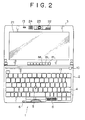
- Fig. 2 is a plan view of the computer in Fig. 1.
- Fig. 3 is a left-hand side view of the computer with the display part 3 swung shut onto the body 2.
- Fig. 4 is a right-hand side view of the computer with the display part 3 swung open 180 degrees relative to the body 2.
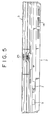
- Fig. 5 is a front view of the computer in Fig. 3.
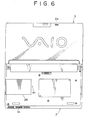
- Fig. 6 is a bottom view of the computer in Fig. 4.
- the face of the body 2 comprises a keyboard 4 and a track point (registered trademark) 5.
- the keyboard 4 is used to input characters, symbols, etc., and the track point 5 is operated to move a mouse cursor.
- a pawl 13 is provided at the upper end of the display part 3. As shown in Fig. 3, with the display part 3 swung closed onto the body 2, the pawl 13 hooks on to a hole 6 in the body 2. At the front of the body 2 is a slide lever 7 furnished in a crosswise movable fashion. The slide lever 7 is used to lock and unlock the pawl 13 so that the pawl 13 is engaged with and disengaged from the hole 6. With the pawl 13 unlocked, the display part 3 may be swung open away from the body 2. Adjacent to the pawl 13 is a microphone 24 which, as depicted in Fig. 6, may pick up sound from both the front and the back side of the body 2.
- the front of the body 2 further comprises a programmable power key (PPK) 9.
- PPK programmable power key
- An air outlet 11 is provided on the right-hand side of the body 2, as shown in Fig. 4.
- An air inlet 14 is provided in Fig. 5.
- To the right of the air outlet 11 is a slot 12 that accommodates a PCMCIA (Personal Computer Memory Card International Association) card (called a PC card).
- PCMCIA Personal Computer Memory Card International Association
- An LCD (liquid crystal display) 21 for displaying images is provided on the front of the display part 3.
- an image pickup part 22 mounted rotatably on the display part 3. More specifically, the image pickup part 22 is rotatable to any position within a range of 180 degrees in the same direction as the LCD 21 and in the opposite direction thereof (i.e., toward the back).
- the image pickup part 22 is furnished with the CCD video camera 23.
- Reference numeral 40 in Fig. 3 denotes a power switch furnished on the left-hand side of the body 2
- reference numeral 25 in Fig. 5 represents an adjusting ring used to adjust the focus of the CCD video camera 23.
- Reference numeral 26 in Fig. 6 stands for a cover that conceals an opening through which to install an additional memory into the body 2
- reference numeral 41 denotes a hole through which to insert a pin to unlock the cover 26.
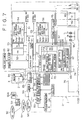
- Fig. 7 illustrates an internal structure of the personal computer 1.
- an internal bus 51 is connected to a CPU (central processing unit) 52, a PC card 53 inserted as needed, a RAM (random access memory) 54, and a graphic chip 81.
- the internal bus 51 is coupled to an external bus 55.
- the external bus 55 for its part, is connected to a hard disk drive (HDD) 56, an I/O (input/output) controller 57, a keyboard controller 58, a track point controller 59, a sound chip 60, an LCD controller 83, and a modem 50.
- HDD hard disk drive
- the CPU 52 is a controller that controls diverse computer functions.
- the PC card 53 is installed as needed when an optional function is to be added.
- an electronic mail program (an application program) 54A, an auto pilot program (another application program) 54B and the OS (operating program) 54C are transferred from the HDD 56 to the RAM 54 and retained therein.
- the electronic mail program 54A is a program that exchanges communication messages with an external entity using a communication line such as a telephone line and by way of a network.
- a received mail acquisition function is specifically included in the electronic mail program 54A.
- the received mail acquisition function checks a mail server 93 to see if a mail box 93A therein contains any mail addressed to this program (i.e., to the user). If any such mail is found in the mail box 93A, the received mail acquisition function carries out a suitable process to acquire that mail.
- the auto pilot program 54B is a program that starts up and carries out a plurality of predetermined processes (or programs) in a predetermined sequence.
- the OS (operating system) 54C controls basic computer functions.
- a typical operating system is Windows 95 (registered trademark).
- the hard disk drive (HDD) 56 connected to the external bus 55 contains the electronic mail program 56A, auto pilot program 56B, and OS (operating system) 56C.
- OS operating system
- the OS 56C, auto pilot program 56B and electronic mail program 56A are transferred successively from the hard disk drive 56 to the RAM 54 and stored in the memory.
- the I/O controller 57 has a microcontroller 61 equipped with an I/O interface 62.
- the microcontroller 61 is constituted by the I/O interface 62, a CPU 63, a RAM 64 and a ROM 69 which are interconnected.
- the RAM 64 includes a key input status register 65, an LED (light-emitting diode) control register 66, a set time register 67, and a register 68.
- the set time register 67 is used to start the operation of a start sequence controller 76 when a time preset by the user (i.e., starting condition) is reached.
- the register 68 holds a correspondence between a preset combination of operation keys (starting condition) on the one hand and an application program to be started on the other hand. When the user inputs the preset combination of operation keys, the corresponding application program (e.g., electronic mail program) is started.
- the key input status register 65 gets and retains an operation key flag.
- the LED control register 66 is used to control the illumination of the message lamp ML indicating that boot-up status of an application program (e.g., electronic mail program) which is held in the register 68.
- a desired time of day may be set to the set time register 67.
- the microcontroller 61 is connected to a backup battery 74.
- the battery 74 allows contents of the registers 65, 66 and 67 to be retained when power to the body 2 is turned off.
- the ROM 69 in the microcontroller 61 contains in advance a wake-up program 70, a key input monitoring program 71, and an LED control program 72.
- the ROM 69 is illustratively composed of an EEPROM (electrically erasable and programmable read only memory).
- the EEPROM is also called a flash memory.
- the microcontroller 61 is connected to an RTC (real-time clock) 75 that keeps the current time.
- the wake-up program 70 in the ROM 69 is a program that checks to see if a preset time in the set time register 67 is reached on the basis of time-of-day data from the RTC 75. When the preset time is reached, the wake-up program 70 starts up a predetermined process (or program).
- the key input monitoring program 71 continuously monitors whether the PPK 9 is pushed by the user.
- the LED control program 72 controls the lighting of the message lamp ML.
- the ROM 69 contains a BIOS (basic input/output system) 73.
- BIOS basic input/output system
- the BIOS is a software program that controls exchanges of data (input and output) between the OS or application software on the one hand and peripheral devices (e.g., display part, keyboard, hard disk drive) on the other hand.
- the keyboard controller 58 connected to the external bus 55 controls input from the keyboard 4.
- the track point controller 59 controls input from the track point 5.
- the sound chip 60 receives input from the microphone 24, and supplies sound signals to the built-in speaker 8.
- the modem 50 permits connection to a communication network 92 such as the Internet and to the mail server 93 through a public telephone line 90 and an Internet service provider 91.
- Image data captured by the CCD video camera 23 are forwarded to a processing part 82 for processing.
- the image data processed by the processing part 82 are input to the graphic chip 81 connected to the internal bus 51.
- the graphic chip 81 stores the input video data into an internal VRAM 81A, and retrieves the data from the memory as needed for output to the LCD controller 83.
- the LCD controller 83 Given the image data from the graphic chip 81, the LCD controller 83 outputs the data to the LCD 21 for display.
- Back lights 84 are provided to illuminate the LCD 21 from the back.
- the power switch 40 is operated to turn on and off the power supply.
- a half-push switch 85 is activated when the shutter button 10 is half-pushed.
- a full-push switch 86 is turned on when the shutter button 10 is fully pushed.
- a reverse switch 87 is turned on when the image pickup part 22 is rotated by 180 degrees (i.e., when the CCD video camera 23 is rotated into a direction suitable for picking up an image on the opposite side of the LCD 21).
- Figs. 8 through 12 depict an inventive structure for attaching a pointing device to a keyboard in accordance with a preferred embodiment of the invention.
- the components with their corresponding parts already shown in Figs. 13 and 14 are given the same reference numerals, and their descriptions are omitted below where appropriate.
- Fig. 8 is a bottom view with a pointing device 101 attached to a back of the keyboard 4, and Fig. 9 is a bottom view with the pointing device 101 removed.
- Fig. 8 three through-holes are formed in a board 102 near its periphery. Screws 201 are inserted into the holes as fastening members. Also near the periphery of the board 102 are two positioning pin holes 205 each having a positioning pin 202 inserted thereinto.
- a cable 203 coming from the pointing device 101 is connected to a controller, not shown. Displacements of a post 104 detected by the pointing device 101 are transmitted through the cable 203 to the controller.
- a hole 4a is formed approximately in the middle of the keyboard 4.
- the post 104 of the pointing device 101 is inserted into the hole 4a.
- a tip of the post 104 constitutes the track point 5 shown in Fig. 1.
- Around the hole 4a are attaching boss holes 204 formed in locations corresponding to the three through-holes in the board 102 of Fig. 8.
- positioning pins 202 are erected in locations corresponding to the positioning pin holes 205.
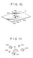
- Fig. 10 is a perspective view of the back of the keyboard in Fig. 9, and Fig. 11 is an enlarged view of a portion A in Fig. 10.
- Fig. 12 is an exploded view illustrating how the pointing device 101 is attached to the back of the keyboard 4, as viewed from the back.
- the post 104 of the pointing device 101 is inserted into the hole 4a in the keyboard 4.
- the positioning pins 202 are inserted into the pin holes 205 for positioning.
- Three screws 201 are inserted into the through-holes 206 in the board 102 and are screwed into the attaching boss holes 204 of the keyboard 4. Driving in the screws 201 fastens the pointing device 101 securely to the back of the keyboard 4.
- the user pushes the post 104 in any of two perpendicularly intersecting directions of the cross-shaped strain gage 103 formed on the board 102.
- the pushing action causes the strain gage 103 to generate currents that are sent over the cable 203 to the controller, not shown. Given the currents, the controller moves the displayed cursor in any of the two directions accordingly.
- the embodiment of the invention described above has no need to use the holding plate 105 to fasten the pointing device 101 onto the keyboard 4.
- the embodiment reduces the number of components and that of assembling steps and thus lowers costs. Because the board 102 is screwed to the keyboard 4 at three points, the strain conventionally experienced in installing a point device is prevented. This eliminates the possibility of strain-incurred malfunctions.
- the board of the pointing member for cursor movement on the display part is fastened at three points to the back of the keyboard by means of fastening members.
- the inventive structure of this embodiment reduces the number of components and that of assembling steps and thus lowers the costs involved. This in turn reduces the incidence of malfunctions.
Abstract
Description
- The present invention relates generally to an information processing apparatus, for example a portable computer. More particularly, the invention relates to a structure for attaching to such a computer a pointing member (called the pointing device hereunder) that incorporates a strain gage to move a displayed cursor on a display part.
- Today, portable information processing apparatus are gaining widespread use. Of these apparatus, portable computers illustratively comprise a body and a display part each. The display part is attached swingingly to the body. The face of the body comprises a keyboard used to input characters, symbols, etc. An LCD for displaying images entered through the keyboard is attached to the display part. The keyboard is equipped with a pointing device incorporating a strain gage, the pointing device being used to move a displayed cursor on the display part.
- Fig. 13 shows a conventional structure for attaching a
pointing device 101 to akeyboard 4. Illustratively, thepointing device 101 has across-shaped strain gage 103 formed by thick-film technology on arectangular PC board 102. Arectangular prism post 104 is erected perpendicularly at the center of thestrain gage 103. - The
pointing device 101 is fitted to thekeyboard 4 as follows: thepost 104 is first inserted into a through-hole 4a formed approximately in the middle of thekeyboard 4. Theboard 102 is placed snugly onto the back of thekeyboard 4. With theboard 102 pushed against the back of thekeyboard 4 using aholding plate 105, theholding plate 105 is fastened to thekeyboard 4 by means of fourscrews 106. More specifically, thescrews 106 are placed intoholes 105a formed near the four corners of theholding pate 105. Thescrews 106 are then screwed into blind tapped holes, not shown, in the back of thekeyboard 4. - Alternatively, four attaching
holes 4b are formed in thekeyboard 4, as shown in Fig. 14. The fourscrews 106, inserted into the attachingholes 4b, are screwed into theholes 105b near the four corners of theholding plate 105. - In the conventional pointing device attaching structure outlined above, the
holding plate 105 is needed in order to fasten theboard 102 onto the back of thekeyboard 4. The structure is thus bound to increase the number of components as well as the number of assembling steps, thus incurring cost increases. Pushing the pointingdevice 101 against the back of thekeyboard 4 by means of theholding plate 105 generates strain and can lead to malfunctions. - It is therefore an object of the present invention to provide an information processing apparatus allowing a pointing device to be installed in an inexpensive manner while alleviating possible malfunctions stemming from the mounting of that pointing device.
- According to one aspect of the invention, there is provided an information processing apparatus comprising: a keyboard for inputting signals; a display part for displaying the signals input through the keyboard; and a pointing member attached to the keyboard and having a board, a strain gage and a post, the strain gage being furnished on the board, the post being erected at a center of the board to transmit strain to the strain gage, the post being further displaced so as to move a cursor on the display part; wherein the board is attached fixedly to a back of the keyboard by means of fastening members; and wherein the post is inserted through a hole in the keyboard so as to protrude from a face of the keyboard.
- In a structure according to a preferred embodiment of the invention, the board may be secured at three points near a periphery of the board.
- In another structure according to a preferred embodiment of the invention, the information processing apparatus may further comprise positioning pins.
- Further particular and preferred aspects of the present invention are set out in the accompanying independent and dependent claims. Features of the dependent claims may be combined with features of the independent claims as appropriate, and in combinations other than those explicitly set out in the claims.
- The present invention will be described further, by way of example only, with reference to preferred embodiments thereof as illustrated in the accompanying drawings, in which:
- Fig. 1 is a perspective view of a portable personal computer in accordance with a preferred embodiment of the invention, with its display part swung open away from its body;
- Fig. 2 is a plan view of the computer in Fig. 1;
- Fig. 3 is a left-hand side view of the computer in Fig. 1 with its display part swung shut onto its body;
- Fig. 4 is a right-hand side view of the computer in Fig. 1 with its display part swung open 180 degrees relative to its body;
- Fig. 5 is a front view of the computer in Fig. 3;
- Fig. 6 is a bottom view of the computer in Fig. 4;
- Fig. 7 is a block diagram outlining electrical circuits of the computer in Fig. 1;
- Fig. 8 is a bottom view with a pointing device attached to a back of a keyboard included in Fig. 1;
- Fig. 9 is a bottom view with the pointing device of Fig. 8 removed;
- Fig. 10 is a perspective view of the setup in Fig. 9;
- Fig. 11 is an enlarged view of a portion A in Fig. 10;
- Fig. 12 is an exploded view illustrating how the pointing device of Fig. 8 is attached to the keyboard;
- Fig. 13 is an exploded view of a typical setup in which a pointing device is attached conventionally to a keyboard; and
- Fig. 14 is an exploded view of another typical setup in which a pointing device is attached conventionally to a keyboard.
-
- A preferred embodiment of this invention is described below. The means claimed as constituting the invention will be described below using specific examples in parentheses where appropriate. However, such specifics are only for illustration purposes and are not limitative of the invention.
- In an information processing apparatus in accordance with an embodiment of the invention, three points of a board (e.g.,
board 102 in Fig. 8) near its periphery are fastened to a back of a keyboard (e.g.,keyboard 4 in Fig. 8) by means of fastening members (e.g.,screws 201 in Fig. 8). A post (e.g.,post 104 in Fig. 8) is inserted through a hole in the keyboard (e.g.,hole 4a in Fig. 9) so as to protrude from a face of the keyboard. - The embodiment of this invention will now be described with reference to the accompanying drawings.
- Figs. 1 through 6 depict a typical portable
personal computer 1 to which the preferred embodiment of the invention is applied. Thepersonal computer 1 is a mini-notebook type personal computer that primarily comprises abody 2 and adisplay part 3 attached swingingly to thebody 2. Fig. 1 is a perspective view of the computer with thedisplay part 3 swung open away from thebody 2. Fig. 2 is a plan view of the computer in Fig. 1. Fig. 3 is a left-hand side view of the computer with thedisplay part 3 swung shut onto thebody 2. Fig. 4 is a right-hand side view of the computer with thedisplay part 3 swung open 180 degrees relative to thebody 2. Fig. 5 is a front view of the computer in Fig. 3. Fig. 6 is a bottom view of the computer in Fig. 4. - The face of the
body 2 comprises akeyboard 4 and a track point (registered trademark) 5. Thekeyboard 4 is used to input characters, symbols, etc., and thetrack point 5 is operated to move a mouse cursor. Also furnished on the body face is aspeaker 8 for sound output along with ashutter button 10 operated to take a picture using aCCD video camera 23 mounted on thedisplay part 3. - A
pawl 13 is provided at the upper end of thedisplay part 3. As shown in Fig. 3, with thedisplay part 3 swung closed onto thebody 2, thepawl 13 hooks on to ahole 6 in thebody 2. At the front of thebody 2 is aslide lever 7 furnished in a crosswise movable fashion. Theslide lever 7 is used to lock and unlock thepawl 13 so that thepawl 13 is engaged with and disengaged from thehole 6. With thepawl 13 unlocked, thedisplay part 3 may be swung open away from thebody 2. Adjacent to thepawl 13 is amicrophone 24 which, as depicted in Fig. 6, may pick up sound from both the front and the back side of thebody 2. - The front of the
body 2 further comprises a programmable power key (PPK) 9. Anair outlet 11 is provided on the right-hand side of thebody 2, as shown in Fig. 4. At the lower end in front of thebody 2 is anair inlet 14 as depicted in Fig. 5. To the right of theair outlet 11 is aslot 12 that accommodates a PCMCIA (Personal Computer Memory Card International Association) card (called a PC card). - An LCD (liquid crystal display) 21 for displaying images is provided on the front of the
display part 3. At the upper end of theLCD 21 is animage pickup part 22 mounted rotatably on thedisplay part 3. More specifically, theimage pickup part 22 is rotatable to any position within a range of 180 degrees in the same direction as theLCD 21 and in the opposite direction thereof (i.e., toward the back). Theimage pickup part 22 is furnished with theCCD video camera 23. - At the lower end of the
display part 3 on the body side is a group of lamps including a power lamp PL, a battery lamp BL, a message lamp ML and other LEDs.Reference numeral 40 in Fig. 3 denotes a power switch furnished on the left-hand side of thebody 2, andreference numeral 25 in Fig. 5 represents an adjusting ring used to adjust the focus of theCCD video camera 23.Reference numeral 26 in Fig. 6 stands for a cover that conceals an opening through which to install an additional memory into thebody 2, andreference numeral 41 denotes a hole through which to insert a pin to unlock thecover 26. - Fig. 7 illustrates an internal structure of the
personal computer 1. As shown in Fig. 7, aninternal bus 51 is connected to a CPU (central processing unit) 52, aPC card 53 inserted as needed, a RAM (random access memory) 54, and agraphic chip 81. Theinternal bus 51 is coupled to anexternal bus 55. Theexternal bus 55, for its part, is connected to a hard disk drive (HDD) 56, an I/O (input/output)controller 57, a keyboard controller 58, a track point controller 59, asound chip 60, anLCD controller 83, and amodem 50. - The
CPU 52 is a controller that controls diverse computer functions. ThePC card 53 is installed as needed when an optional function is to be added. - When the
personal computer 1 is booted up, an electronic mail program (an application program) 54A, an auto pilot program (another application program) 54B and the OS (operating program) 54C are transferred from theHDD 56 to theRAM 54 and retained therein. - The
electronic mail program 54A is a program that exchanges communication messages with an external entity using a communication line such as a telephone line and by way of a network. A received mail acquisition function is specifically included in theelectronic mail program 54A. The received mail acquisition function checks amail server 93 to see if amail box 93A therein contains any mail addressed to this program (i.e., to the user). If any such mail is found in themail box 93A, the received mail acquisition function carries out a suitable process to acquire that mail. - The auto pilot program 54B is a program that starts up and carries out a plurality of predetermined processes (or programs) in a predetermined sequence.
- The OS (operating system) 54C controls basic computer functions. A typical operating system is Windows 95 (registered trademark).
- The hard disk drive (HDD) 56 connected to the
external bus 55 contains theelectronic mail program 56A, auto pilot program 56B, and OS (operating system) 56C. During the booting process, theOS 56C, auto pilot program 56B andelectronic mail program 56A are transferred successively from thehard disk drive 56 to theRAM 54 and stored in the memory. - The I/
O controller 57 has amicrocontroller 61 equipped with an I/O interface 62. Themicrocontroller 61 is constituted by the I/O interface 62, aCPU 63, aRAM 64 and aROM 69 which are interconnected. TheRAM 64 includes a keyinput status register 65, an LED (light-emitting diode)control register 66, aset time register 67, and aregister 68. The settime register 67 is used to start the operation of astart sequence controller 76 when a time preset by the user (i.e., starting condition) is reached. Theregister 68 holds a correspondence between a preset combination of operation keys (starting condition) on the one hand and an application program to be started on the other hand. When the user inputs the preset combination of operation keys, the corresponding application program (e.g., electronic mail program) is started. - When the fingertip-operated programmable power key (PPK) 9 is pushed, the key
input status register 65 gets and retains an operation key flag. The LED control register 66 is used to control the illumination of the message lamp ML indicating that boot-up status of an application program (e.g., electronic mail program) which is held in theregister 68. A desired time of day may be set to the settime register 67. - The
microcontroller 61 is connected to abackup battery 74. Thebattery 74 allows contents of theregisters body 2 is turned off. - The
ROM 69 in themicrocontroller 61 contains in advance a wake-upprogram 70, a keyinput monitoring program 71, and anLED control program 72. TheROM 69 is illustratively composed of an EEPROM (electrically erasable and programmable read only memory). The EEPROM is also called a flash memory. Themicrocontroller 61 is connected to an RTC (real-time clock) 75 that keeps the current time. - The wake-up
program 70 in theROM 69 is a program that checks to see if a preset time in the settime register 67 is reached on the basis of time-of-day data from theRTC 75. When the preset time is reached, the wake-upprogram 70 starts up a predetermined process (or program). The keyinput monitoring program 71 continuously monitors whether the PPK 9 is pushed by the user. TheLED control program 72 controls the lighting of the message lamp ML. - Furthermore, the
ROM 69 contains a BIOS (basic input/output system) 73. The BIOS is a software program that controls exchanges of data (input and output) between the OS or application software on the one hand and peripheral devices (e.g., display part, keyboard, hard disk drive) on the other hand. - The keyboard controller 58 connected to the
external bus 55 controls input from thekeyboard 4. The track point controller 59 controls input from thetrack point 5. - The
sound chip 60 receives input from themicrophone 24, and supplies sound signals to the built-inspeaker 8. - The
modem 50 permits connection to acommunication network 92 such as the Internet and to themail server 93 through apublic telephone line 90 and anInternet service provider 91. - Image data captured by the
CCD video camera 23 are forwarded to a processing part 82 for processing. The image data processed by the processing part 82 are input to thegraphic chip 81 connected to theinternal bus 51. Thegraphic chip 81 stores the input video data into aninternal VRAM 81A, and retrieves the data from the memory as needed for output to theLCD controller 83. Given the image data from thegraphic chip 81, theLCD controller 83 outputs the data to theLCD 21 for display. Back lights 84 are provided to illuminate theLCD 21 from the back. - The
power switch 40 is operated to turn on and off the power supply. A half-push switch 85 is activated when theshutter button 10 is half-pushed. A full-push switch 86 is turned on when theshutter button 10 is fully pushed. Areverse switch 87 is turned on when theimage pickup part 22 is rotated by 180 degrees (i.e., when theCCD video camera 23 is rotated into a direction suitable for picking up an image on the opposite side of the LCD 21). - Figs. 8 through 12 depict an inventive structure for attaching a pointing device to a keyboard in accordance with a preferred embodiment of the invention. In these figures, the components with their corresponding parts already shown in Figs. 13 and 14 are given the same reference numerals, and their descriptions are omitted below where appropriate.
- Fig. 8 is a bottom view with a
pointing device 101 attached to a back of thekeyboard 4, and Fig. 9 is a bottom view with thepointing device 101 removed. In Fig. 8, three through-holes are formed in aboard 102 near its periphery.Screws 201 are inserted into the holes as fastening members. Also near the periphery of theboard 102 are two positioning pin holes 205 each having apositioning pin 202 inserted thereinto. Acable 203 coming from thepointing device 101 is connected to a controller, not shown. Displacements of apost 104 detected by thepointing device 101 are transmitted through thecable 203 to the controller. - In Fig. 9, a
hole 4a is formed approximately in the middle of thekeyboard 4. Thepost 104 of thepointing device 101 is inserted into thehole 4a. A tip of thepost 104 constitutes thetrack point 5 shown in Fig. 1. Around thehole 4a are attaching boss holes 204 formed in locations corresponding to the three through-holes in theboard 102 of Fig. 8. Likewise, positioning pins 202 are erected in locations corresponding to the positioning pin holes 205. Fig. 10 is a perspective view of the back of the keyboard in Fig. 9, and Fig. 11 is an enlarged view of a portion A in Fig. 10. - Fig. 12 is an exploded view illustrating how the
pointing device 101 is attached to the back of thekeyboard 4, as viewed from the back. Thepost 104 of thepointing device 101 is inserted into thehole 4a in thekeyboard 4. The positioning pins 202 are inserted into the pin holes 205 for positioning. Threescrews 201 are inserted into the through-holes 206 in theboard 102 and are screwed into the attachingboss holes 204 of thekeyboard 4. Driving in thescrews 201 fastens thepointing device 101 securely to the back of thekeyboard 4. - To move a cursor, not shown, on the
LCD 21 in Fig. 1, the user pushes thepost 104 in any of two perpendicularly intersecting directions of thecross-shaped strain gage 103 formed on theboard 102. The pushing action causes thestrain gage 103 to generate currents that are sent over thecable 203 to the controller, not shown. Given the currents, the controller moves the displayed cursor in any of the two directions accordingly. - Unlike conventional setups, the embodiment of the invention described above has no need to use the holding
plate 105 to fasten thepointing device 101 onto thekeyboard 4. The embodiment reduces the number of components and that of assembling steps and thus lowers costs. Because theboard 102 is screwed to thekeyboard 4 at three points, the strain conventionally experienced in installing a point device is prevented. This eliminates the possibility of strain-incurred malfunctions. - In the information processing apparatus according to the preferred embodiment of the invention, as described, the board of the pointing member for cursor movement on the display part is fastened at three points to the back of the keyboard by means of fastening members. The inventive structure of this embodiment reduces the number of components and that of assembling steps and thus lowers the costs involved. This in turn reduces the incidence of malfunctions.
- While a preferred embodiment of the invention has been described using specific terms, such description is for illustrative purposes only, and it is to be understood that changes and variations many be made without departing from the spirit or scope of the claims that follow.
Claims (3)
- An information processing apparatus comprising:a keyboard for inputting signals;a display part for displaying said signals input through said keyboard; anda pointing member attached to said keyboard and having a board, a strain gage and a post, said strain gage being furnished on said board, said post being erected at a center of said board to transmit strain to said strain gage, said post being further displaced so as to move a cursor on said display part;wherein said board is attached fixedly to a back of said keyboard by means of fastening members; andwherein said post is inserted through a hole in said keyboard so as to protrude from a face of said keyboard.
- An information processing apparatus according to claim 1, wherein said board is secured at three points near a periphery of said board.
- An information processing apparatus according to claim 1, further comprising positioning pins.
Applications Claiming Priority (2)
| Application Number | Priority Date | Filing Date | Title |
|---|---|---|---|
| JP18373098 | 1998-06-30 | ||
| JP10183730A JP2000020233A (en) | 1998-06-30 | 1998-06-30 | Information processor |
Publications (2)
| Publication Number | Publication Date |
|---|---|
| EP0969351A2 true EP0969351A2 (en) | 2000-01-05 |
| EP0969351A3 EP0969351A3 (en) | 2002-12-18 |
Family
ID=16140974
Family Applications (1)
| Application Number | Title | Priority Date | Filing Date |
|---|---|---|---|
| EP99304980A Ceased EP0969351A3 (en) | 1998-06-30 | 1999-06-24 | Information processing apparatus |
Country Status (5)
| Country | Link |
|---|---|
| US (1) | US6697047B2 (en) |
| EP (1) | EP0969351A3 (en) |
| JP (1) | JP2000020233A (en) |
| KR (1) | KR100667600B1 (en) |
| TW (1) | TW439023B (en) |
Families Citing this family (9)
| Publication number | Priority date | Publication date | Assignee | Title |
|---|---|---|---|---|
| US7974775B1 (en) * | 1999-11-05 | 2011-07-05 | Angela Masson | Electronic kit bag |
| TWM312103U (en) * | 2006-11-24 | 2007-05-11 | Quanta Comp Inc | Connection strucutre |
| TWI348311B (en) | 2007-10-09 | 2011-09-01 | Quanta Comp Inc | Portable computer system and operating method thereof |
| TWI368157B (en) * | 2008-03-26 | 2012-07-11 | Elan Microelectronics Corp | Stress sensor and electronic device haveing the same |
| WO2010050974A1 (en) * | 2008-10-31 | 2010-05-06 | Hewlett-Packard Development Company, L.P. | A system with a microphone within a mobile computing system |
| JP5606401B2 (en) * | 2011-06-23 | 2014-10-15 | アルプス電気株式会社 | Input device with movable touchpad |
| JP5337279B1 (en) * | 2012-05-21 | 2013-11-06 | 株式会社東芝 | Electronics |
| USD869458S1 (en) * | 2018-05-03 | 2019-12-10 | Compal Electronics, Inc. | Notebook computer with camera module |
| USD869457S1 (en) * | 2018-05-03 | 2019-12-10 | Compal Electronics, Inc. | Notebook computer with camera module |
Citations (2)
| Publication number | Priority date | Publication date | Assignee | Title |
|---|---|---|---|---|
| US5640178A (en) * | 1994-09-16 | 1997-06-17 | Fujitsu Limited | Pointing device |
| US5835977A (en) * | 1996-08-19 | 1998-11-10 | Kamentser; Boris | Force transducer with co-planar strain gauges |
Family Cites Families (7)
| Publication number | Priority date | Publication date | Assignee | Title |
|---|---|---|---|---|
| US4492830A (en) * | 1983-03-28 | 1985-01-08 | Wico Corporation | Joystick with single-leaf spring switch |
| US5541622A (en) * | 1990-07-24 | 1996-07-30 | Incontrol Solutions, Inc. | Miniature isometric joystick |
| JP2584201B2 (en) * | 1994-01-14 | 1997-02-26 | インターナショナル・ビジネス・マシーンズ・コーポレイション | Power transducer, computer system and keyboard |
| TW290666B (en) * | 1994-03-02 | 1996-11-11 | Alps Electric Co Ltd | |
| US5872320A (en) * | 1996-08-19 | 1999-02-16 | Bokam Engineering | Force transducer with co-planar strain gauges |
| US6040823A (en) * | 1997-12-02 | 2000-03-21 | Cts | Computer keyboard having top molded housing with rigid pointing stick integral and normal to front surface of housing as one unit part to be used with strain sensors in navigational control |
| TW468128B (en) * | 1999-01-08 | 2001-12-11 | Acer Peripherals Inc | Pointing stick and its manufacturing method |
-
1998
- 1998-06-30 JP JP10183730A patent/JP2000020233A/en active Pending
-
1999
- 1999-06-22 TW TW088110488A patent/TW439023B/en not_active IP Right Cessation
- 1999-06-24 EP EP99304980A patent/EP0969351A3/en not_active Ceased
- 1999-06-28 US US09/340,901 patent/US6697047B2/en not_active Expired - Fee Related
- 1999-06-29 KR KR1019990025144A patent/KR100667600B1/en not_active IP Right Cessation
Patent Citations (2)
| Publication number | Priority date | Publication date | Assignee | Title |
|---|---|---|---|---|
| US5640178A (en) * | 1994-09-16 | 1997-06-17 | Fujitsu Limited | Pointing device |
| US5835977A (en) * | 1996-08-19 | 1998-11-10 | Kamentser; Boris | Force transducer with co-planar strain gauges |
Also Published As
| Publication number | Publication date |
|---|---|
| US20020093482A1 (en) | 2002-07-18 |
| KR20000006550A (en) | 2000-01-25 |
| US6697047B2 (en) | 2004-02-24 |
| TW439023B (en) | 2001-06-07 |
| JP2000020233A (en) | 2000-01-21 |
| EP0969351A3 (en) | 2002-12-18 |
| KR100667600B1 (en) | 2007-01-15 |
Similar Documents
| Publication | Publication Date | Title |
|---|---|---|
| KR100685152B1 (en) | Information processing apparatus | |
| KR100677171B1 (en) | Information processing apparatus | |
| US8190993B2 (en) | Menu selection using a rotating dial and button | |
| US5841631A (en) | Latch block control for media bay module | |
| CN100356293C (en) | Portable computer with camera | |
| US20010027529A1 (en) | Authentication device, authentication method, program storage medium and information processing device | |
| JP4366746B2 (en) | Information processing apparatus and method, and recording medium | |
| US6697047B2 (en) | Information processing apparatus | |
| US6493828B1 (en) | Information processing apparatus, information processing method, and program storage medium | |
| US6980236B1 (en) | Information processing apparatus with image capturing function method and storage medium thereof | |
| JP2000076284A (en) | Information processor, information processing method and provision medium | |
| JP2001298654A (en) | Information processor | |
| JP2000022347A (en) | Information processor | |
| JP2001084060A (en) | Information processor | |
| JP2000152138A (en) | Information processor, information processing method and medium stored with program | |
| JPH09114554A (en) | Electronic equipment | |
| JP3263757B2 (en) | Information processing device | |
| JP2000020161A (en) | Information processor | |
| KR200185034Y1 (en) | Computer body flame | |
| JP2000242368A (en) | Computer device | |
| JP2000020221A (en) | Information processor | |
| JP2000242400A (en) | Computer device and power source control method for computer device | |
| JP2000242374A (en) | Computer device and process control method for computer device | |
| JP2000020162A (en) | Information processor | |
| JP2001245185A (en) | Information processing apparatus |
Legal Events
| Date | Code | Title | Description |
|---|---|---|---|
| PUAI | Public reference made under article 153(3) epc to a published international application that has entered the european phase |
Free format text: ORIGINAL CODE: 0009012 |
|
| AK | Designated contracting states |
Kind code of ref document: A2 Designated state(s): AT BE CH CY DE DK ES FI FR GB GR IE IT LI LU MC NL PT SE |
|
| AX | Request for extension of the european patent |
Free format text: AL;LT;LV;MK;RO;SI |
|
| PUAL | Search report despatched |
Free format text: ORIGINAL CODE: 0009013 |
|
| AK | Designated contracting states |
Kind code of ref document: A3 Designated state(s): AT BE CH CY DE DK ES FI FR GB GR IE IT LI LU MC NL PT SE |
|
| AX | Request for extension of the european patent |
Free format text: AL;LT;LV;MK;RO;SI |
|
| RIC1 | Information provided on ipc code assigned before grant |
Free format text: 7G 06F 1/16 A, 7G 06F 3/02 B, 7G 05G 9/047 B, 7G 06K 11/18 B |
|
| 17P | Request for examination filed |
Effective date: 20030527 |
|
| AKX | Designation fees paid |
Designated state(s): DE FR GB |
|
| 17Q | First examination report despatched |
Effective date: 20040330 |
|
| STAA | Information on the status of an ep patent application or granted ep patent |
Free format text: STATUS: THE APPLICATION HAS BEEN REFUSED |
|
| 18R | Application refused |
Effective date: 20041207 |