EP0967757A2 - Information processing apparatus and method and computer program for enabling a function change - Google Patents
Information processing apparatus and method and computer program for enabling a function change Download PDFInfo
- Publication number
- EP0967757A2 EP0967757A2 EP99304526A EP99304526A EP0967757A2 EP 0967757 A2 EP0967757 A2 EP 0967757A2 EP 99304526 A EP99304526 A EP 99304526A EP 99304526 A EP99304526 A EP 99304526A EP 0967757 A2 EP0967757 A2 EP 0967757A2
- Authority
- EP
- European Patent Office
- Prior art keywords
- information processing
- processing apparatus
- function
- inquiry
- information
- Prior art date
- Legal status (The legal status is an assumption and is not a legal conclusion. Google has not performed a legal analysis and makes no representation as to the accuracy of the status listed.)
- Withdrawn
Links
Images


Classifications
-
- H—ELECTRICITY
- H04—ELECTRIC COMMUNICATION TECHNIQUE
- H04L—TRANSMISSION OF DIGITAL INFORMATION, e.g. TELEGRAPHIC COMMUNICATION
- H04L12/00—Data switching networks
- H04L12/28—Data switching networks characterised by path configuration, e.g. LAN [Local Area Networks] or WAN [Wide Area Networks]
- H04L12/40—Bus networks
- H04L12/40052—High-speed IEEE 1394 serial bus
- H04L12/40117—Interconnection of audio or video/imaging devices
-
- G—PHYSICS
- G06—COMPUTING; CALCULATING OR COUNTING
- G06F—ELECTRIC DIGITAL DATA PROCESSING
- G06F13/00—Interconnection of, or transfer of information or other signals between, memories, input/output devices or central processing units
-
- H—ELECTRICITY
- H04—ELECTRIC COMMUNICATION TECHNIQUE
- H04B—TRANSMISSION
- H04B1/00—Details of transmission systems, not covered by a single one of groups H04B3/00 - H04B13/00; Details of transmission systems not characterised by the medium used for transmission
- H04B1/06—Receivers
- H04B1/16—Circuits
- H04B1/20—Circuits for coupling gramophone pick-up, recorder output, or microphone to receiver
- H04B1/205—Circuits for coupling gramophone pick-up, recorder output, or microphone to receiver with control bus for exchanging commands between units
-
- H—ELECTRICITY
- H04—ELECTRIC COMMUNICATION TECHNIQUE
- H04L—TRANSMISSION OF DIGITAL INFORMATION, e.g. TELEGRAPHIC COMMUNICATION
- H04L61/00—Network arrangements, protocols or services for addressing or naming
-
- H—ELECTRICITY
- H04—ELECTRIC COMMUNICATION TECHNIQUE
- H04L—TRANSMISSION OF DIGITAL INFORMATION, e.g. TELEGRAPHIC COMMUNICATION
- H04L61/00—Network arrangements, protocols or services for addressing or naming
- H04L61/45—Network directories; Name-to-address mapping
-
- H—ELECTRICITY
- H04—ELECTRIC COMMUNICATION TECHNIQUE
- H04L—TRANSMISSION OF DIGITAL INFORMATION, e.g. TELEGRAPHIC COMMUNICATION
- H04L67/00—Network arrangements or protocols for supporting network services or applications
- H04L67/01—Protocols
- H04L67/12—Protocols specially adapted for proprietary or special-purpose networking environments, e.g. medical networks, sensor networks, networks in vehicles or remote metering networks
-
- H—ELECTRICITY
- H04—ELECTRIC COMMUNICATION TECHNIQUE
- H04L—TRANSMISSION OF DIGITAL INFORMATION, e.g. TELEGRAPHIC COMMUNICATION
- H04L2101/00—Indexing scheme associated with group H04L61/00
- H04L2101/60—Types of network addresses
- H04L2101/604—Address structures or formats
-
- H—ELECTRICITY
- H04—ELECTRIC COMMUNICATION TECHNIQUE
- H04L—TRANSMISSION OF DIGITAL INFORMATION, e.g. TELEGRAPHIC COMMUNICATION
- H04L69/00—Network arrangements, protocols or services independent of the application payload and not provided for in the other groups of this subclass
- H04L69/30—Definitions, standards or architectural aspects of layered protocol stacks
- H04L69/32—Architecture of open systems interconnection [OSI] 7-layer type protocol stacks, e.g. the interfaces between the data link level and the physical level
- H04L69/322—Intralayer communication protocols among peer entities or protocol data unit [PDU] definitions
- H04L69/329—Intralayer communication protocols among peer entities or protocol data unit [PDU] definitions in the application layer [OSI layer 7]
Definitions
- the present invention relates to information processing apparatus and methods, providing media and computer programs for enabling a change in a function to be detected.
- An AV/C command set is specified for controlling AV units connected through the IEEE 1394 bus.
- a descriptor is provided in order to show various pieces of information of a unit to any other unit.
- the term "unit” indicates a unit itself and the term “subunit” indicates a function of a unit, in the AV/C command set.
- a function of a unit is described in a subunit identifier descriptor.
- a controller unit (unit which accesses any other AV unit) reads the subunit identifier descriptor of a target unit (unit which is accessed from any other AV unit) only once when the system is built up.
- the subunit identifier descriptor is also changed accordingly.
- the controller unit since the controller unit reads the subunit identifier descriptor of the target unit only once when the system is built up, however, even if the subunit identifier descriptor is changed, the change cannot be detected.
- An object of the present invention is to allow a controller unit, when a function of a target unit is changed, to detect the change.
- an information processing apparatus connectable to any other information processing apparatus through a bus, including: storage means for storing a function; updating means for updating the contents of the storage means according to a change of the function; and reporting means for reporting to the any other information apparatus that the updating means has updated the contents of the storage means.
- the storage means stores a function; the updating means updates the contents of the storage means according to a change of the function; and the reporting means reports to the any other information apparatus that the updating means has updated the contents of the storage means.
- the present invention allows this change information to be reported to a controller unit.
- an information processing method for an information processing apparatus connectable to any other information processing apparatus through a bus including: a storage step for storing a function; an updating step for updating the contents stored in the storage step, according to a change of the function; and a reporting step for reporting to the any other information processing apparatus that the contents stored in the storage step have been updated in the updating step.
- a computer program, or a providing medium for providing a program which makes an information processing apparatus connected to any other information processing apparatus through a bus execute processing, the processing including: a storage step for storing a function; an updating step for updating the contents stored in the storage step, according to a change of the function; and a reporting step for reporting to the any other information processing apparatus that the contents stored in the storage step have been updated in the updating step.
- a function is stored in the storage step; the contents stored in the storage step are updated in the updating step according to a change of the function; and it is reported to the any other information processing apparatus in the reporting step that the contents stored in the storage step have been updated in the updating step.
- any other information processing apparatus can detect the function change.
- an information processing apparatus connectable to any other information processing apparatus through a bus, including: inquiry means for inquiring of the any other information processing apparatus whether a function of the any other information processing apparatus has been changed; and receiving means for receiving the acknowledgment of the inquiry sent from the inquiry means, from the any other information processing apparatus.
- the inquiry means inquires of the any other information processing apparatus whether a function of the any other information processing apparatus has been changed; and the receiving means receives the acknowledgment of the inquiry sent from the inquiry means, from the any other information processing apparatus.
- an information processing method for an information processing apparatus connectable to any other information processing apparatus through a bus, including: an inquiry step for inquiring of the any other information processing apparatus whether a function of the any other information processing apparatus has been changed; and a receiving step for receiving the acknowledgment of the inquiry sent in the inquiry step, from the any other information processing apparatus.
- a computer program, or a providing medium for providing a program which makes an information processing apparatus connected to any other information processing apparatus through a bus execute processing, the processing including: an inquiry step for inquiring of the any other information processing apparatus whether a function of the any other information processing apparatus has been changed; and a receiving step for receiving the acknowledgment of the inquiry sent in the inquiry step, from the any other information processing apparatus.
- the computer program and the providing medium determine whether a function of the any other information processing apparatus has been changed is inquired of the any other information processing apparatus in the inquiry step; and the acknowledgment of the inquiry sent in the inquiry step is received from the any other information processing apparatus in the receiving step.
- the information processing apparatus since whether a function of any other information processing apparatus has been changed can be inquired and its response can be received, control according to a function change of any other information processing apparatus is allowed.
- Fig. 1 is a block diagram of an information processing system to which an information processing apparatus of a preferred embodiments of the present invention is applied.
- Fig. 2 is a view showing a data structure of a subunit identifier descriptor.
- Fig. 3 is a view showing a format of a subunit identifier descriptor.
- Fig. 4 is a view showing the contents of a generation_ID field shown in Fig. 3.
- Fig. 5 is a view showing the contents of a list_ID field shown in Fig. 3.
- Fig. 6 is a view showing a format of a subunit identifier descriptor in a preferred embodiment of the present system.
- Fig. 7 is a view showing a format of a tuner subunit identifier descriptor.
- Fig. 8 is a view showing a format of a system_specification field shown in Fig. 7.
- Fig. 9 is a view showing the contents of a system_id item shown in Fig. 8.
- Fig. 10 is a view of a stack model of an AV/C command set.
- Fig. 11 is a view showing a relationship between an FCP command and a response.
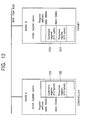
- Fig. 12 is a view showing a further detailed relationship between the command and the response shown in Fig. 11.
- Fig. 13 is a view showing a data structure of an AV/C command packet.
- Fig. 14 is a view showing examples of AV/C commands.
- Fig. 15, which includes Fig. 15A and Fig. 15B, is a view showing an AV/C command and a response.
- Fig. 16 which includes Fig. 16A to Fig. 16C, is a view showing a NOTIFY command and a response.
- Fig. 17 is a flowchart of processing in the controller unit.
- Fig. 18 is a flowchart of processing in the target unit.
- An information processing apparatus of a preferred embodiment is connectable to any other information processing apparatus through a bus, and includes: storage means (a subunit identifier descriptor 71 shown in Fig. 6, for example) for storing a function; updating means (a step S22 shown in Fig. 18, for example) for updating the contents of the storage means according to a change of the function; and reporting means (a step S26 shown in Fig. 18, for example) for reporting to the any other information apparatus that the updating means has updated the contents of the storage means.
- storage means a subunit identifier descriptor 71 shown in Fig. 6, for example
- updating means a step S22 shown in Fig. 18, for example
- reporting means a step S26 shown in Fig. 18, for example
- An information processing apparatus of a preferred embodiment is connectable to any other information processing apparatus through a bus, and includes: inquiry means (a step S3 shown in Fig. 17, for example) for inquiring of the any other information processing apparatus whether a function of the any other information processing apparatus has been changed; and receiving means (a step S5 shown in Fig. 17, for example) for receiving the acknowledgment of the inquiry sent from the inquiry means, from the any other information processing apparatus.
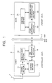
- Fig. 1 is a block diagram showing a structure of an information processing system to which a preferred embodiment of the present invention is applied.
- a tuner 2 is connected to a digital video cassette recorder (DVCR) 3 through an IEEE 1394 bus 4.
- the tuner 2 serves as a controller unit and the DVCR 3 serves as a target unit.
- An AV/C command set is used for controlling the DVCR 3.
- a tuning section 11 of the tuner 2 selects a digital broadcasting signal (multiplexed stream) and receives it through an antenna 1 according to an instruction from a control section 13.
- the tuning section 11 sends the received digital broadcasting signal to a demultiplexer section 12.
- the demultiplexer section 12 extracts a video signal and an audio signal from the sent digital broadcasting signal and outputs them to the IEEE 1394 bus through a 1394 interface section 14.
- a 1394 interface section 22 of the DVCR 3 receives data on the IEEE 1394 bus according to an instruction from a control section 21.
- the 1394 interface section 22 sends the received data to a recording and reproduction section 23.
- the recording and reproduction section 23 compresses the received video signal and the received audio signal, multiplexes them, and records them on a magnetic tape not shown.
- the recording and reproduction section 23 detects data on a magnetic tape, extracts it, decompresses it, and outputs to a unit not shown.
- Fig. 2 shows the data structure of the subunit identifier descriptor.
- the subunit identifier descriptor is formed of hierarchical lists.
- a list indicates, for example, a channel which can be received, for a tuner, and for a disk, it indicates the music recorded therein.
- a list at the highest layer in a hierarchical structure is called a root list.
- a list 0, for example, serves as the root list for its lower lists.
- a list 2 to list (n-1) also serve as root lists.
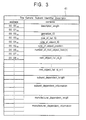
- Fig. 3 is a format of a general subunit identifier descriptor 41 used in an existing system.
- the subunit identifier descriptor 41 has attribute information related to a function in its contents.
- a descriptor_length field indicates the length (the number of bytes) of the descriptor structure, excluding the length of the descriptor_length field itself.
- a generation_ID field shows the version of the AV/C command set, and is currently set to 00h (h indicates hexadecimal notation) as shown in Fig. 4.
- 00h shows that the data structure and the commands used are in the version 3.0 of the AV/C general specification. As shown in Fig. 4, all values other than 00h are reserved for future specifications.
- a size_of_list_ID field indicates the byte count of a list ID.
- a size_of_object_ID field indicates the byte count of an object ID.
- a size_of_object_position field shows the position (byte count) in the list used for reference during control.
- a number_of_root_object_lists field indicates the number of root object lists.
- a root_object_list id field shows an ID for discriminating the highest root object list in a separate hierarchy.
- the subunit_dependent_length field shows the byte count of the following subunit_dependent_information field.
- the subunit_dependent_information field indicates the information unique to a function.
- a manufacturer_dependent_length field shows the byte count of the following manufacturer_dependent_information field.
- the manufacturer_dependent_information field shows the specification information of a vendor (manufacturer). When a descriptor does not have manufacturer dependent information, the field thereof does not exist.
- Fig. 5 shows list-ID assignment ranges. As shown in Fig. 5, a range of 0000h to 0FFFh and that of 4000h to FFFFh are reserved for assignment ranges for future specifications. A range of 1000h to 3FFFh and that of 10000h to the maximum list-ID value are prepared for discriminating the dependent information of function types.
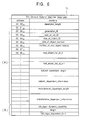
- a subunit identifier descriptor used in the system of a preferred embodiment of the present invention will be described below by referring to Fig. 6. Since the fields in a zone A in Fig. 6 are the same as those described with Fig. 3, descriptions thereof are omitted.
- a zone B in Fig. 6 shows fields added to the format shown in Fig. 3.
- An info_type field shows whether a function of an AV unit changes or not.
- a length field indicates the byte count of the following info_type_dependent field.
- the info_type_dependent field shows the dependent information of dynamic_capability and is defined by a one-byte flag (eight flags).
- a controller unit (the tuner 2, for example) can determine whether a function of a target unit (the DVCR 3, for example) is changed or not, by referencing the info_type field of the subunit identifier descriptor 71 for the target unit.
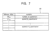
- a tuner subunit identifier descriptor will be described below by referring to Figs. 7 to 9.
- the tuner subunit identifier descriptor a feature of a broadcasting system which the tuner supports is described.
- a multi-system tuner since the tuner supports two or more broadcasting systems, a plurality of object lists exist.
- Fig. 7 shows a format of a root object list in the tuner subunit.
- a number_of_systems field indicates the number of broadcasting systems which the tuner subunit supports.
- a system_specification field shows the specification of each broadcasting system and conforms to a format shown in Fig. 8.
- Fig. 8 shows the format of the system_specification field shown in Fig. 7.
- a specification_length item shows the length (byte count) of the following descriptor structure, excluding that of the specification_length item itself.
- a system_id item is used for discriminating the broadcasting systems which the tuner subunit supports, and is specified as shown in Fig. 9.
- an analog video broadcasting system is used.
- an analog audio broadcasting system is used.
- a digital video broadcasting (DVB) system is used.
- a system_id item of 21h is reserved for a digital audio broadcasting (DAB) system.
- a system_id item of 22h is also reserved for a digital television (DTV). All the other values are reserved for future specifications.
- An implementation_profile_id item indicates a profile id to be executed in the system id.
- a number_of_subsystem_label item shows the number of service providers which the tuner handles.
- a sub_system_label_length item indicates the byte count of the following sub_system_label item. The sub_system_label item is used for discriminating service providers, and corresponds, for example, to "PerfecTV" and "Canal Plus" in the DVB system.
- a number_of_antennas item indicates the number of antennas which can be used for the broadcasting system.
- An antenna_specification item shows the specification of an antenna.
- a system_specific_information length item indicates the byte count of the following system_specific_information item. The system_specific_information item shows clear information of the broadcasting system.
- Fig. 10 shows a stack model of the AV/C command set.
- a physical layer 111, a link layer 112, a transaction layer 113, and serial bus management 114 conform to IEEE 1394.
- a function control protocol (FCP) 115 conforms to IEC 61883.
- An AV/C command set 116 conforms to a 1394 TA specification.
- Fig. 11 is a view showing commands and responses of the FCP 115 shown in Fig. 10.
- the FCP is a protocol for controlling AV units on IEEE 1394.
- a controlling unit is called a controller and a controlled unit is called a target.
- FCP commands and responses are transferred between nodes with the use of write transactions in IEEE 1394 asynchronous communication.
- the target receives data, it sends back an acknowledgment to the controller for confirmation of receiving.
- Fig. 12 is a view showing a further detailed relationship between FCP commands and responses.
- a node A is connected to a node B through an IEEE 1394 bus.
- the node A serves as a controller, and the node B serves as a target.
- Each of the node A and the node B is provided with a 512-byte command register and a 512-byte response register.
- the controller writes a command message into a command register 123 of the target to notify of the instruction.
- the target writes a response message into a response register 122 of the controller to notify of the response.
- control information is transferred.
- the type of a command set transmitted in the FCP is indicated in a CTS field among data fields shown in Fig. 13.
- Fig. 13 shows a data structure of an asynchronous packet in an AV/C command.
- the AV/C command set is used for controlling an AV unit and has a CTS field (command set ID) of 0000.
- An AV/C command frame and a response frame are transferred between nodes with the use of the FCP.
- To apply no load to the bus and the AV units it is determined that a response should be sent within 100 ms from when a command is received.
- data in an asynchronous packet is formed of 32 bits (one quadlet) in the horizontal direction.
- the upper part of the packet in the figure shows a packet header and the lower part of the packet shows a data block.
- a destination_ID field indicates the destination.
- the CTS field indicates a command-set ID. For the AV/C command set, the CTS field is set to 0000.
- a ctype/response field shows the function type of a command when the packet has a command, and shows the processing result of the received command when the packet has a response.
- CONTROL commands for controlling a function externally
- STATUS commands for inquiring a status externally
- GENERAL INQUIRY command inquiring whether an opcode is supported
- SPECIFIC INQUIRY commands inquiring whether an opcode and operands are supported
- NOTIFY commands for requesting a change of the state to be report to the outside.
- a response is sent back according to the type of a command.
- Responses to a CONTROL command include “NOT IMPLEMENTED,” “ACCEPTED,” “REJECTED,” and “INTERIM.”
- Responses to a STATUS command include “NOT IMPLEMENTED,” “REJECTED,” “IN TRANSITION,” and “STABLE.”
- Responses to a GENERAL INQUIRY command and a SPECIFIC INQUIRY command include “IMPLEMENTED” and “NOT IMPLEMENTED.”
- Reponses to a NOTIFY command include “NOT IMPLEMENTED,” “REJECTED,” “INTERIM,” and “CHANGED.”
- a subunit_type field identifies a function in the unit, and can be "tape recorder/player,” or "tuner,” for example.
- a subunit id field is used for addressing as an identification number.
- An opcode field shows a command.
- An operand field indicates a parameter of the command.
- An additional operands field is added as required.
- a padding field is also added as required.
- a data cyclic redundancy check (CRC) field is used for checking an error during data transfer.
- Fig. 14 shows AV/C command examples. Examples in the ctype/response field are shown in a list A of Fig. 14. The upper section indicates commands and the lower section indicates responses.
- a code of 0000 is assigned to a CONTROL command, 0001 to a STATUS command, 0010 is to a SPECIFIC INQUIRY command, 0011 to a NOTIFY command, and 0100 to a GENERAL INQUIRY command. Codes from 0101 to 0111 are reserved for future specifications.
- a code of 1000 is assigned to "NOT IMPLEMENTED,” 1001 to “ACCEPTED,” 1010 to “REJECTED,” 1011 to “IN TRANSITION,” and 1100 to “IMPLEMENTED/STABLE,” 1101 to “CHANGED,”, and 1111 to “INTERIM.”
- a code of 1110 is reserved for a future specification.
- Examples in the subunit_type field are shown in a list B of Fig. 14.
- a code of 00000 is assigned to "video monitor,” 00011 to “disk recorder/player,” 00100 to “tape recorder/player,” 00101 to “tuner,” 00111 to “video camera,” 11100 to “vendor unique,” and 11110 to a subunit type extended to the next byte.
- a code of 11111 is assigned to the unit, which means that a command or a response is sent to the unit itself, for example, in a case in which the power source is turned on or off.
- Examples of the opcode field are shown in a list C of Fig. 14.
- One opcode table corresponds to each subunit type.
- An opcode field for a subunit_type field of tape recorder/player is shown in the figure.
- An operand is defined for each opcode.
- An opcode of 00h is assigned to "VENDOR-DEPENDENT,” 50h to "SEARCH MODE,” 51h to "TIMECODE,” 52h to "ATN,” 60h to "OPEN MIC,” 61h to "READ MIC,” 62h to “WRITE MIC,” C1h to "LOAD MEDIUM,” C2h to “RECORD,” C3h to “PLAY,” and C4h to "WIND.”
- Figs. 15A and 15B show an example of an AV/C command and a response.
- the controller sends a command shown in Fig. 15A to the target. Since the AV/C command set is used in this command, the CTS field is set to 0000.
- the ctype field is set to 0000 to use a CONTROL command, which controls a function externally (see the list A of Fig. 14).
- the subunit_type field is set to 00100 since the type is tape recorder/player (see the list B of Fig. 14).
- the id field is set to 000 to show ID0.
- the opcode field is set to C3h, which indicates play (see the list C of Fig. 14).
- the operand field is set to 75h, which shows FORWARD.
- the response field is set to 1001 to show that the command has been accepted (see the list A of Fig. 14). Since the fields other than the response field have the same codes as those shown in Fig. 15A, descriptions thereof are omitted.
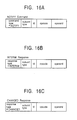
- Figs. 16A to 16C show a NOTIFY command and responses.
- a NOTIFY command (shown in Fig. 16A) requests that a status change be reported to the outside. With the use of this command, a change of the subunit identifier descriptor of the target unit is detected.
- the target unit receives a NOTIFY command, it sends back an INTERIM response (shown in Fig. 16B) to the controller. If the subunit identifier descriptor of the target unit is actually changed, the target unit sends back a CHANGED response (shown in Fig. 16C) to the controller.
- Fig. 17 is a flowchart of processing in the controller unit.
- the control section 13 of the tuner 2 reads the subunit identifier descriptor 71 of the DVCR 3 through the IEEE 1394 bus 4 in a step S1, and the procedure proceeds to a step S2.
- the control section 13 determines whether the DVCR 3 is an AV unit of new type (whether it has the descriptor shown in Fig. 6).
- the processing is finished.
- the control section 13 sends a NOTIFY command (shown in Fig. 16A) to the DVCR 3 in a step S3.
- the control section 13 receives an INTERIM response (shown in Fig. 16B) from the DVCR 3, which indicates that the DVCR 3 has received the NOTIFY command.
- the control section 13 determines in a step S5 whether it receives a CHANGED response (shown in Fig. 16C), which shows that a function has been changed. If it is determined in the step S5 that a CHANGED response has not been received, this step is repeated. When it is determined in the step S5 that a CHANGED response has been received, the processing returns to the step S1, and the subsequent steps are repeated.
- Fig. 18 is a flowchart of processing in the target unit.
- the control section 21 of the DVCR 3 determines in a step S21 whether a function has been changed. If it is determined in the step S21 that a function is not changed, this step is repeated. When it is determined in the step S21 that a function has been changed, the processing proceeds to a step S22.
- the control section 21 updates the subunit identifier descriptor 71 according to the change in function, and the processing proceeds to a step S23.
- the control section 21 determines in the step S23 whether it reports the function change to an old-type unit in addition to a new-type unit.
- the control section 21 controls the 1394 interface section 22 so as to generate a bus reset in a step S24. With this reset, an old-type unit not shown in addition to the tuner 2 read the updated subunit identifier descriptor 71, and the processing is finished.
- the control section 21 determines in a step S25 whether it has received a NOTIFY command from the tuner 2. When it is determined in the step S25 that a NOTIFY command has not been received, the processing is finished. When it is determined in the step S25 that a NOTIFY command has been received, the control section 21 sends a CHANGED response to the tuner 2 in a step S26 and the processing is finished.
- the DVCR is taken as an example of the target AV unit in which a function is changed.
- the present invention can also be applied to other AV units such as a CD deck unit.
- providing media which provide the user with a computer program that executes the above processing include information recording media such as magnetic disks and CD-ROMs and network transfer media such as the Internet and digital satellites.
Abstract
In an embodiment of the present invention, the control
section of a tuner reads the subunit identifier descriptor of
a digital video cassette recorder (DVCR) through an IEEE 1394
bus in a step S1, and a procedure proceeds to a step S2. In
the step S2, the control section determines whether the DVCR
is an audio-visual (AV) unit of new type. When it is
determined that the DVCR is an AV unit of old type, the
processing is finished. When it is determined that the DVCR
is a new-type unit, the control section sends a NOTIFY
command to the DVCR in a step S3. In a step S4, the control
section receives an INTERIM response from the DVCR, which
indicates that the DVCR has received the NOTIFY command. The
control section determines in a step S5 whether it receives
a CHANGED response, which shows that a function has been
changed. If it is determined that a CHANGED response has not
been received, the step S5 is repeated. When it is
determined that a CHANGED response has been received, the
processing returns to the step S1, and the subsequent steps
are repeated.
Description
- The present invention relates to information processing apparatus and methods, providing media and computer programs for enabling a change in a function to be detected.
- An AV/C command set is specified for controlling AV units connected through the IEEE 1394 bus. In the AV/C command set, a descriptor is provided in order to show various pieces of information of a unit to any other unit. The term "unit" indicates a unit itself and the term "subunit" indicates a function of a unit, in the AV/C command set. A function of a unit is described in a subunit identifier descriptor.
- It is conventionally considered that a function of a unit is fixed in general, and when a subunit identifier descriptor, which indicates a function of a unit, is once specified, it does not change. Therefore, among AV units, a controller unit (unit which accesses any other AV unit) reads the subunit identifier descriptor of a target unit (unit which is accessed from any other AV unit) only once when the system is built up.
- In the above system, when a function of the target unit is changed due to downloaded software or a mounted Memory Stick, for example, the subunit identifier descriptor is also changed accordingly.
- In the conventional system, since the controller unit reads the subunit identifier descriptor of the target unit only once when the system is built up, however, even if the subunit identifier descriptor is changed, the change cannot be detected.
- An object of the present invention is to allow a controller unit, when a function of a target unit is changed, to detect the change.
- In accordance with one aspect of the present invention, there is provided an information processing apparatus connectable to any other information processing apparatus through a bus, including: storage means for storing a function; updating means for updating the contents of the storage means according to a change of the function; and reporting means for reporting to the any other information apparatus that the updating means has updated the contents of the storage means.
- In the information processing apparatus, the storage means stores a function; the updating means updates the contents of the storage means according to a change of the function; and the reporting means reports to the any other information apparatus that the updating means has updated the contents of the storage means.
- Hence, when a function of a target audio-visual (AV) unit is changed in a case in which AV units are connected through an IEEE (Institute of Electrical and Electronic Engineers) 1394 bus, the present invention allows this change information to be reported to a controller unit.
- In accordance with another aspect of the present invention, there is provided an information processing method for an information processing apparatus connectable to any other information processing apparatus through a bus, including: a storage step for storing a function; an updating step for updating the contents stored in the storage step, according to a change of the function; and a reporting step for reporting to the any other information processing apparatus that the contents stored in the storage step have been updated in the updating step.
- In accordance with another aspect of the present invention, there is provided a computer program, or a providing medium for providing a program, which makes an information processing apparatus connected to any other information processing apparatus through a bus execute processing, the processing including: a storage step for storing a function; an updating step for updating the contents stored in the storage step, according to a change of the function; and a reporting step for reporting to the any other information processing apparatus that the contents stored in the storage step have been updated in the updating step.
- In the information processing method, computer program and the providing medium, a function is stored in the storage step; the contents stored in the storage step are updated in the updating step according to a change of the function; and it is reported to the any other information processing apparatus in the reporting step that the contents stored in the storage step have been updated in the updating step.
- According to the information processing apparatus, the information processing method, the computer program and the providing medium, since the contents of a storage is updated according to a change in function and the change is reported, any other information processing apparatus can detect the function change.
- In accordance with yet another aspect of the present invention, there is provided an information processing apparatus connectable to any other information processing apparatus through a bus, including: inquiry means for inquiring of the any other information processing apparatus whether a function of the any other information processing apparatus has been changed; and receiving means for receiving the acknowledgment of the inquiry sent from the inquiry means, from the any other information processing apparatus.
- In the information processing apparatus, the inquiry means inquires of the any other information processing apparatus whether a function of the any other information processing apparatus has been changed; and the receiving means receives the acknowledgment of the inquiry sent from the inquiry means, from the any other information processing apparatus.
- In accordance with a further aspect of the present invention, there is provided an information processing method for an information processing apparatus connectable to any other information processing apparatus through a bus, including: an inquiry step for inquiring of the any other information processing apparatus whether a function of the any other information processing apparatus has been changed; and a receiving step for receiving the acknowledgment of the inquiry sent in the inquiry step, from the any other information processing apparatus.
- In accordance with a still further aspect of the present invention, there is provided a computer program, or a providing medium for providing a program, which makes an information processing apparatus connected to any other information processing apparatus through a bus execute processing, the processing including: an inquiry step for inquiring of the any other information processing apparatus whether a function of the any other information processing apparatus has been changed; and a receiving step for receiving the acknowledgment of the inquiry sent in the inquiry step, from the any other information processing apparatus.
- In the information processing method, the computer program and the providing medium, whether a function of the any other information processing apparatus has been changed is inquired of the any other information processing apparatus in the inquiry step; and the acknowledgment of the inquiry sent in the inquiry step is received from the any other information processing apparatus in the receiving step.
- According to the information processing apparatus, the information processing method, the computer program and the providing medium, since whether a function of any other information processing apparatus has been changed can be inquired and its response can be received, control according to a function change of any other information processing apparatus is allowed.
- Further particular and preferred aspects of the present invention are set out in the accompanying independent and dependent claims. Features of the dependent claims may be combined with features of the independent claims as appropriate, and in combinations other than those explicitly set out in the claims.
- The present invention will be described further, by way of example only, with reference to preferred embodiments thereof as illustrated in the accompanying drawings, in which:
- Fig. 1 is a block diagram of an information processing system to which an information processing apparatus of a preferred embodiments of the present invention is applied.
- Fig. 2 is a view showing a data structure of a subunit identifier descriptor.
- Fig. 3 is a view showing a format of a subunit identifier descriptor.
- Fig. 4 is a view showing the contents of a generation_ID field shown in Fig. 3.
- Fig. 5 is a view showing the contents of a list_ID field shown in Fig. 3.
- Fig. 6 is a view showing a format of a subunit identifier descriptor in a preferred embodiment of the present system.
- Fig. 7 is a view showing a format of a tuner subunit identifier descriptor.
- Fig. 8 is a view showing a format of a system_specification field shown in Fig. 7.
- Fig. 9 is a view showing the contents of a system_id item shown in Fig. 8.
- Fig. 10 is a view of a stack model of an AV/C command set.
- Fig. 11 is a view showing a relationship between an FCP command and a response.
- Fig. 12 is a view showing a further detailed relationship between the command and the response shown in Fig. 11.
- Fig. 13 is a view showing a data structure of an AV/C command packet.
- Fig. 14 is a view showing examples of AV/C commands.
- Fig. 15, which includes Fig. 15A and Fig. 15B, is a view showing an AV/C command and a response.
- Fig. 16, which includes Fig. 16A to Fig. 16C, is a view showing a NOTIFY command and a response.
- Fig. 17 is a flowchart of processing in the controller unit.
- Fig. 18 is a flowchart of processing in the target unit.
- An embodiment of the present invention will be described below. To clarify the relationship between each means to be specified in the claims of the present invention and the following embodiment, the features of the present invention will be described below first with the embodiment corresponding to each means being added in parentheses after the means. This description does not mean that each means is limited to the described example.
- An information processing apparatus of a preferred embodiment is connectable to any other information processing apparatus through a bus, and includes: storage means (a
subunit identifier descriptor 71 shown in Fig. 6, for example) for storing a function; updating means (a step S22 shown in Fig. 18, for example) for updating the contents of the storage means according to a change of the function; and reporting means (a step S26 shown in Fig. 18, for example) for reporting to the any other information apparatus that the updating means has updated the contents of the storage means. - An information processing apparatus of a preferred embodiment is connectable to any other information processing apparatus through a bus, and includes: inquiry means (a step S3 shown in Fig. 17, for example) for inquiring of the any other information processing apparatus whether a function of the any other information processing apparatus has been changed; and receiving means (a step S5 shown in Fig. 17, for example) for receiving the acknowledgment of the inquiry sent from the inquiry means, from the any other information processing apparatus.
- Fig. 1 is a block diagram showing a structure of an information processing system to which a preferred embodiment of the present invention is applied. In the present embodiment, a
tuner 2 is connected to a digital video cassette recorder (DVCR) 3 through an IEEE 1394 bus 4. Thetuner 2 serves as a controller unit and the DVCR 3 serves as a target unit. An AV/C command set is used for controlling theDVCR 3. - A
tuning section 11 of thetuner 2 selects a digital broadcasting signal (multiplexed stream) and receives it through anantenna 1 according to an instruction from acontrol section 13. Thetuning section 11 sends the received digital broadcasting signal to ademultiplexer section 12. Thedemultiplexer section 12 extracts a video signal and an audio signal from the sent digital broadcasting signal and outputs them to theIEEE 1394 bus through a 1394interface section 14. - A 1394
interface section 22 of theDVCR 3 receives data on theIEEE 1394 bus according to an instruction from acontrol section 21. The 1394interface section 22 sends the received data to a recording andreproduction section 23. In recording, according to an instruction from thecontrol section 21, the recording andreproduction section 23 compresses the received video signal and the received audio signal, multiplexes them, and records them on a magnetic tape not shown. In reproduction, the recording andreproduction section 23 detects data on a magnetic tape, extracts it, decompresses it, and outputs to a unit not shown. - The data structure of a subunit identifier descriptor in the AV/C command set used in the information processing system shown in Fig. 1 will be described below by referring to Figs. 2 to 5. Fig. 2 shows the data structure of the subunit identifier descriptor. As shown in Fig. 2, the subunit identifier descriptor is formed of hierarchical lists. A list indicates, for example, a channel which can be received, for a tuner, and for a disk, it indicates the music recorded therein. A list at the highest layer in a hierarchical structure is called a root list. A
list 0, for example, serves as the root list for its lower lists. Alist 2 to list (n-1) also serve as root lists. There exist root lists corresponding to the number of objects. For example, an object is a channel in digital broadcasting when an AV unit is a tuner. All lists in one hierarchy have common information. - Fig. 3 is a format of a general
subunit identifier descriptor 41 used in an existing system. Thesubunit identifier descriptor 41 has attribute information related to a function in its contents. A descriptor_length field indicates the length (the number of bytes) of the descriptor structure, excluding the length of the descriptor_length field itself. A generation_ID field shows the version of the AV/C command set, and is currently set to 00h (h indicates hexadecimal notation) as shown in Fig. 4. 00h shows that the data structure and the commands used are in the version 3.0 of the AV/C general specification. As shown in Fig. 4, all values other than 00h are reserved for future specifications. - A size_of_list_ID field indicates the byte count of a list ID. A size_of_object_ID field indicates the byte count of an object ID. A size_of_object_position field shows the position (byte count) in the list used for reference during control. A number_of_root_object_lists field indicates the number of root object lists. A root_object_list id field shows an ID for discriminating the highest root object list in a separate hierarchy.
- The subunit_dependent_length field shows the byte count of the following subunit_dependent_information field. The subunit_dependent_information field indicates the information unique to a function. A manufacturer_dependent_length field shows the byte count of the following manufacturer_dependent_information field. The manufacturer_dependent_information field shows the specification information of a vendor (manufacturer). When a descriptor does not have manufacturer dependent information, the field thereof does not exist.
- Fig. 5 shows list-ID assignment ranges. As shown in Fig. 5, a range of 0000h to 0FFFh and that of 4000h to FFFFh are reserved for assignment ranges for future specifications. A range of 1000h to 3FFFh and that of 10000h to the maximum list-ID value are prepared for discriminating the dependent information of function types.
- A subunit identifier descriptor used in the system of a preferred embodiment of the present invention will be described below by referring to Fig. 6. Since the fields in a zone A in Fig. 6 are the same as those described with Fig. 3, descriptions thereof are omitted. A zone B in Fig. 6 shows fields added to the format shown in Fig. 3. An info_type field shows whether a function of an AV unit changes or not. A notation of info_type=dynamic_capability shows that a function of the AV unit having this notation may be changed. A length field indicates the byte count of the following info_type_dependent field. The info_type_dependent field shows the dependent information of dynamic_capability and is defined by a one-byte flag (eight flags). When a
flag 0 = 0, the AV unit is considered to have static_capability (the function is fixed). When theflag 0 is 1, the AV unit is considered to have dynamic_capability (the function is dynamic).Flags 1 to 7 are reserved for future specifications. A controller unit (thetuner 2, for example) can determine whether a function of a target unit (theDVCR 3, for example) is changed or not, by referencing the info_type field of thesubunit identifier descriptor 71 for the target unit. - A tuner subunit identifier descriptor will be described below by referring to Figs. 7 to 9. In the tuner subunit identifier descriptor, a feature of a broadcasting system which the tuner supports is described. In a multi-system tuner, since the tuner supports two or more broadcasting systems, a plurality of object lists exist. Fig. 7 shows a format of a root object list in the tuner subunit. A number_of_systems field indicates the number of broadcasting systems which the tuner subunit supports. A system_specification field shows the specification of each broadcasting system and conforms to a format shown in Fig. 8.
- Fig. 8 shows the format of the system_specification field shown in Fig. 7. A specification_length item shows the length (byte count) of the following descriptor structure, excluding that of the specification_length item itself. A system_id item is used for discriminating the broadcasting systems which the tuner subunit supports, and is specified as shown in Fig. 9. When the system_id item is set to 10h, an analog video broadcasting system is used. When the system_id item is set to llh, an analog audio broadcasting system is used. When the system_id item is set to 20h, a digital video broadcasting (DVB) system is used. A system_id item of 21h is reserved for a digital audio broadcasting (DAB) system. A system_id item of 22h is also reserved for a digital television (DTV). All the other values are reserved for future specifications.
- An implementation_profile_id item indicates a profile id to be executed in the system id. A number_of_subsystem_label item shows the number of service providers which the tuner handles. A sub_system_label_length item indicates the byte count of the following sub_system_label item. The sub_system_label item is used for discriminating service providers, and corresponds, for example, to "PerfecTV" and "Canal Plus" in the DVB system. A number_of_antennas item indicates the number of antennas which can be used for the broadcasting system. An antenna_specification item shows the specification of an antenna. A system_specific_information length item indicates the byte count of the following system_specific_information item. The system_specific_information item shows clear information of the broadcasting system.
- The AV/C command set used in the information processing system shown in Fig. 1 will be described below by referring to Figs. 10 to 15. Fig. 10 shows a stack model of the AV/C command set. As shown in Fig. 10, a
physical layer 111, alink layer 112, atransaction layer 113, andserial bus management 114 conform toIEEE 1394. A function control protocol (FCP) 115 conforms to IEC 61883. An AV/C command set 116 conforms to a 1394 TA specification. - Fig. 11 is a view showing commands and responses of the
FCP 115 shown in Fig. 10. The FCP is a protocol for controlling AV units onIEEE 1394. As shown in Fig. 11, a controlling unit is called a controller and a controlled unit is called a target. FCP commands and responses are transferred between nodes with the use of write transactions inIEEE 1394 asynchronous communication. When the target receives data, it sends back an acknowledgment to the controller for confirmation of receiving. - Fig. 12 is a view showing a further detailed relationship between FCP commands and responses. A node A is connected to a node B through an
IEEE 1394 bus. The node A serves as a controller, and the node B serves as a target. Each of the node A and the node B is provided with a 512-byte command register and a 512-byte response register. As shown in Fig. 12, the controller writes a command message into acommand register 123 of the target to notify of the instruction. Conversely, the target writes a response message into aresponse register 122 of the controller to notify of the response. With a pair of these two messages, control information is transferred. The type of a command set transmitted in the FCP is indicated in a CTS field among data fields shown in Fig. 13. - Fig. 13 shows a data structure of an asynchronous packet in an AV/C command. The AV/C command set is used for controlling an AV unit and has a CTS field (command set ID) of 0000. An AV/C command frame and a response frame are transferred between nodes with the use of the FCP. To apply no load to the bus and the AV units, it is determined that a response should be sent within 100 ms from when a command is received. As shown in Fig. 13, data in an asynchronous packet is formed of 32 bits (one quadlet) in the horizontal direction. The upper part of the packet in the figure shows a packet header and the lower part of the packet shows a data block. A destination_ID field indicates the destination.
- The CTS field indicates a command-set ID. For the AV/C command set, the CTS field is set to 0000. A ctype/response field shows the function type of a command when the packet has a command, and shows the processing result of the received command when the packet has a response. Commands are roughly divided into four types, (1) CONTROL commands for controlling a function externally, (2) STATUS commands for inquiring a status externally, (3) GENERAL INQUIRY command (inquiring whether an opcode is supported) and SPECIFIC INQUIRY commands (inquiring whether an opcode and operands are supported) for externally inquiring whether a control command is supported, and (4) NOTIFY commands for requesting a change of the state to be report to the outside.
- A response is sent back according to the type of a command. Responses to a CONTROL command include "NOT IMPLEMENTED," "ACCEPTED," "REJECTED," and "INTERIM." Responses to a STATUS command include "NOT IMPLEMENTED," "REJECTED," "IN TRANSITION," and "STABLE." Responses to a GENERAL INQUIRY command and a SPECIFIC INQUIRY command include "IMPLEMENTED" and "NOT IMPLEMENTED." Reponses to a NOTIFY command include "NOT IMPLEMENTED," "REJECTED," "INTERIM," and "CHANGED."
- A subunit_type field identifies a function in the unit, and can be "tape recorder/player," or "tuner," for example. To discriminate a plurality of subunits of the same type, a subunit id field is used for addressing as an identification number. An opcode field shows a command. An operand field indicates a parameter of the command. An additional operands field is added as required. A padding field is also added as required. A data cyclic redundancy check (CRC) field is used for checking an error during data transfer.
- Fig. 14 shows AV/C command examples. Examples in the ctype/response field are shown in a list A of Fig. 14. The upper section indicates commands and the lower section indicates responses. A code of 0000 is assigned to a CONTROL command, 0001 to a STATUS command, 0010 is to a SPECIFIC INQUIRY command, 0011 to a NOTIFY command, and 0100 to a GENERAL INQUIRY command. Codes from 0101 to 0111 are reserved for future specifications. A code of 1000 is assigned to "NOT IMPLEMENTED," 1001 to "ACCEPTED," 1010 to "REJECTED," 1011 to "IN TRANSITION," and 1100 to "IMPLEMENTED/STABLE," 1101 to "CHANGED,", and 1111 to "INTERIM." A code of 1110 is reserved for a future specification.
- Examples in the subunit_type field are shown in a list B of Fig. 14. A code of 00000 is assigned to "video monitor," 00011 to "disk recorder/player," 00100 to "tape recorder/player," 00101 to "tuner," 00111 to "video camera," 11100 to "vendor unique," and 11110 to a subunit type extended to the next byte. A code of 11111 is assigned to the unit, which means that a command or a response is sent to the unit itself, for example, in a case in which the power source is turned on or off.
- Examples of the opcode field are shown in a list C of Fig. 14. One opcode table corresponds to each subunit type. An opcode field for a subunit_type field of tape recorder/player is shown in the figure. An operand is defined for each opcode. An opcode of 00h is assigned to "VENDOR-DEPENDENT," 50h to "SEARCH MODE," 51h to "TIMECODE," 52h to "ATN," 60h to "OPEN MIC," 61h to "READ MIC," 62h to "WRITE MIC," C1h to "LOAD MEDIUM," C2h to "RECORD," C3h to "PLAY," and C4h to "WIND."
- Figs. 15A and 15B show an example of an AV/C command and a response. To play the DVCR 3 (target) shown in Fig. 1, for example, the controller sends a command shown in Fig. 15A to the target. Since the AV/C command set is used in this command, the CTS field is set to 0000. The ctype field is set to 0000 to use a CONTROL command, which controls a function externally (see the list A of Fig. 14). The subunit_type field is set to 00100 since the type is tape recorder/player (see the list B of Fig. 14). The id field is set to 000 to show ID0. The opcode field is set to C3h, which indicates play (see the list C of Fig. 14). The operand field is set to 75h, which shows FORWARD. When the target is played, it sends back a response shown in Fig. 15B to the controller. The response field is set to 1001 to show that the command has been accepted (see the list A of Fig. 14). Since the fields other than the response field have the same codes as those shown in Fig. 15A, descriptions thereof are omitted.
- Figs. 16A to 16C show a NOTIFY command and responses. A NOTIFY command (shown in Fig. 16A) requests that a status change be reported to the outside. With the use of this command, a change of the subunit identifier descriptor of the target unit is detected. When the target unit receives a NOTIFY command, it sends back an INTERIM response (shown in Fig. 16B) to the controller. If the subunit identifier descriptor of the target unit is actually changed, the target unit sends back a CHANGED response (shown in Fig. 16C) to the controller.
- Operations of the controller unit and the target unit shown in Fig. 1 in accordance with the preferred embodiment will be described below by referring to Fig. 17 and Fig. 18. Fig. 17 is a flowchart of processing in the controller unit. When the processing in the controller unit starts, the
control section 13 of thetuner 2 reads thesubunit identifier descriptor 71 of theDVCR 3 through theIEEE 1394 bus 4 in a step S1, and the procedure proceeds to a step S2. In the step S2, thecontrol section 13 determines whether theDVCR 3 is an AV unit of new type (whether it has the descriptor shown in Fig. 6). When it is determined in the step S2 that theDVCR 3 is an AV unit of old type (that it has the descriptor shown in Fig. 3), the processing is finished. - When it is determined in the step S2 that the
DVCR 3 is a new-type unit, thecontrol section 13 sends a NOTIFY command (shown in Fig. 16A) to theDVCR 3 in a step S3. In a step S4, thecontrol section 13 receives an INTERIM response (shown in Fig. 16B) from theDVCR 3, which indicates that theDVCR 3 has received the NOTIFY command. Thecontrol section 13 determines in a step S5 whether it receives a CHANGED response (shown in Fig. 16C), which shows that a function has been changed. If it is determined in the step S5 that a CHANGED response has not been received, this step is repeated. When it is determined in the step S5 that a CHANGED response has been received, the processing returns to the step S1, and the subsequent steps are repeated. - Fig. 18 is a flowchart of processing in the target unit. When the processing in the target unit starts, the
control section 21 of theDVCR 3 determines in a step S21 whether a function has been changed. If it is determined in the step S21 that a function is not changed, this step is repeated. When it is determined in the step S21 that a function has been changed, the processing proceeds to a step S22. - In the step S22, the
control section 21 updates thesubunit identifier descriptor 71 according to the change in function, and the processing proceeds to a step S23. Thecontrol section 21 determines in the step S23 whether it reports the function change to an old-type unit in addition to a new-type unit. When it is determined in the step S23 that the function change is to be reported to an old-type unit in addition to a new-type unit, thecontrol section 21 controls the 1394interface section 22 so as to generate a bus reset in a step S24. With this reset, an old-type unit not shown in addition to thetuner 2 read the updatedsubunit identifier descriptor 71, and the processing is finished. - When it is determined in the step S23 that the function change is not to be reported to an old-type unit, the
control section 21 determines in a step S25 whether it has received a NOTIFY command from thetuner 2. When it is determined in the step S25 that a NOTIFY command has not been received, the processing is finished. When it is determined in the step S25 that a NOTIFY command has been received, thecontrol section 21 sends a CHANGED response to thetuner 2 in a step S26 and the processing is finished. - In the present embodiment, the DVCR is taken as an example of the target AV unit in which a function is changed. The present invention can also be applied to other AV units such as a CD deck unit.
- In the present specification, providing media which provide the user with a computer program that executes the above processing include information recording media such as magnetic disks and CD-ROMs and network transfer media such as the Internet and digital satellites.
- Although particular embodiments have been described herein, it will be appreciated that the invention is not limited thereto and that many modifications and additions thereto may be made within the scope of the invention. For example, various combinations of the features of the following dependent claims can be made with the features of the independent claims without departing from the scope of the present invention.
Claims (18)
- An information processing apparatus connectable to any other information processing apparatus through a bus, comprising:storage means for storing a function;updating means for updating the contents of said storage means according to a change of the function; andreporting means for reporting to the any other information apparatus that said updating means has updated the contents of said storage means.
- An information processing apparatus according to Claim 1, further comprising storage means for storing information indicating whether the function is changed.
- An information processing apparatus according to Claim 1, wherein said reporting means reports to the any other information apparatus that the contents of said storage means have been updated, by writing information based on the updating of the contents of said storage means into prescribed storage means of the any other information apparatus.
- An information processing apparatus according to Claim 1, wherein said reporting means reports to the any other information apparatus that the contents of said storage means have been updated, by resetting the bus.
- An information processing method for an information processing apparatus connectable to any other information processing apparatus through a bus, comprising:a storage step for storing a function;an updating step for updating the contents stored in said storage step, according to a change of the function; anda reporting step for reporting to the any other information processing apparatus that the contents stored in said storage step have been updated in said updating step.
- An information processing method according to Claim 5, wherein the any other information processing apparatus is notified that the contents stored in said storage step have been updated, in said reporting step by writing information based on the updating of the contents stored in said storage step into prescribed storage means of the any other information apparatus.
- An information processing method according to Claim 5, wherein the any other information processing apparatus is notified that the contents stored in said storage step have been updated, in said reporting step by resetting the bus.
- A providing medium for providing a program which makes an information processing apparatus connected to any other information processing apparatus through a bus execute processing, the processing comprising:a storage step for storing a function;an updating step for updating the contents stored in said storage step, according to a change of the function; anda reporting step for reporting to the any other information processing apparatus that the contents stored in said storage step have been updated in said updating step.
- A computer program for making an information processing apparatus connected to any other information processing apparatus through a bus execute processing, the processing comprising:a storage step for storing a function;an updating step for updating the contents stored in said storage step, according to a change of the function; anda reporting step for reporting to the any other information processing apparatus that the contents stored in said storage step have been updated in said updating step.
- An information processing apparatus connectable to any other information processing apparatus through a bus, comprising:inquiry means for inquiring of the any other information processing apparatus whether a function of the any other information processing apparatus has been changed; andreceiving means for receiving the acknowledgment of the inquiry sent from said inquiry means, from the any other information processing apparatus.
- An information processing apparatus according to Claim 10, further comprising inquiry means for inquiring of the any other information processing apparatus whether a function of the any other information processing apparatus is changed.
- An information processing apparatus according to Claim 10, wherein said inquiry means performs the inquiry by writing an inquiry command into prescribed storage means of the any other information apparatus.
- An information processing method for an information processing apparatus connectable to any other information processing apparatus through a bus, comprising:an inquiry step for inquiring of the any other information processing apparatus whether a function of the any other information processing apparatus has been changed; anda receiving step for receiving the acknowledgment of the inquiry sent in said inquiry step, from the any other information processing apparatus.
- An information processing method according to Claim 13, further comprising an inquiry step for inquiring of the any other information processing apparatus whether a function of the any other information processing apparatus is changed.
- An information processing method according to Claim 13, wherein the inquiry is performed in said inquiry step by writing an inquiry command into prescribed storage means of the any other information apparatus.
- A providing medium for providing a program which makes an information processing apparatus connected to any other information processing apparatus through a bus execute processing, the processing comprising:an inquiry step for inquiring of the any other information processing apparatus whether a function of the any other information processing apparatus has been changed; anda receiving step for receiving the acknowledgment of the inquiry sent in said inquiry step, from the any other information processing apparatus.
- A providing medium for providing a program according to Claim 16, the processing further comprising an inquiry step for inquiring of the any other information processing apparatus whether a function of the any other information processing apparatus is changed.
- A computer program for making an information processing apparatus connected to any other information processing apparatus through a bus execute processing, the processing comprising:an inquiry step for inquiring of the any other information processing apparatus whether a function of the any other information processing apparatus has been changed; anda receiving step for receiving the acknowledgment of the inquiry sent in said inquiry step, from the any other information processing apparatus.
Applications Claiming Priority (2)
| Application Number | Priority Date | Filing Date | Title |
|---|---|---|---|
| JP10167955A JP2000003330A (en) | 1998-06-16 | 1998-06-16 | Device and method for information processing, and provision medium |
| JP16795598 | 1998-06-16 |
Publications (1)
| Publication Number | Publication Date |
|---|---|
| EP0967757A2 true EP0967757A2 (en) | 1999-12-29 |
Family
ID=15859152
Family Applications (1)
| Application Number | Title | Priority Date | Filing Date |
|---|---|---|---|
| EP99304526A Withdrawn EP0967757A2 (en) | 1998-06-16 | 1999-06-10 | Information processing apparatus and method and computer program for enabling a function change |
Country Status (5)
| Country | Link |
|---|---|
| EP (1) | EP0967757A2 (en) |
| JP (1) | JP2000003330A (en) |
| KR (1) | KR20000006189A (en) |
| CN (1) | CN1244677A (en) |
| TW (1) | TW442735B (en) |
Cited By (7)
| Publication number | Priority date | Publication date | Assignee | Title |
|---|---|---|---|---|
| WO2001050681A2 (en) * | 2000-01-03 | 2001-07-12 | Digital Harmony Technologies, Inc. | Method and apparatus for configuring parameters and presenting status in a distributed communications system |
| FR2823626A1 (en) * | 2001-04-12 | 2002-10-18 | Canon Kk | Communications terminal connected functional unit configuration connection having functional unit configured following time characteristic and controller node automatically changing functional unit state. |
| WO2003058469A1 (en) * | 2001-12-28 | 2003-07-17 | Intel Corporation | Communicating transaction types between agents in a computer system using packet headers including an extended type/extended length field |
| WO2003058470A1 (en) * | 2001-12-28 | 2003-07-17 | Intel Corporation | Communicating message request transaction types between agents in a computer system using multiple message groups |
| US7191375B2 (en) | 2001-12-28 | 2007-03-13 | Intel Corporation | Method and apparatus for signaling an error condition to an agent not expecting a completion |
| US7191267B2 (en) * | 2000-03-06 | 2007-03-13 | Sony Corporation | Electronic device system, controlling device and controlling method |
| US7581026B2 (en) | 2001-12-28 | 2009-08-25 | Intel Corporation | Communicating transaction types between agents in a computer system using packet headers including format and type fields |
Families Citing this family (2)
| Publication number | Priority date | Publication date | Assignee | Title |
|---|---|---|---|---|
| US6738835B1 (en) * | 1999-05-28 | 2004-05-18 | Sony Corporation | Information processing apparatus and method, and recording medium |
| JP2001024653A (en) * | 1999-07-05 | 2001-01-26 | Sony Corp | Information processor, method therefor and medium |
-
1998
- 1998-06-16 JP JP10167955A patent/JP2000003330A/en not_active Withdrawn
-
1999
- 1999-06-07 TW TW088109437A patent/TW442735B/en not_active IP Right Cessation
- 1999-06-10 EP EP99304526A patent/EP0967757A2/en not_active Withdrawn
- 1999-06-15 KR KR1019990022241A patent/KR20000006189A/en not_active Application Discontinuation
- 1999-06-16 CN CN99111005A patent/CN1244677A/en active Pending
Cited By (16)
| Publication number | Priority date | Publication date | Assignee | Title |
|---|---|---|---|---|
| WO2001050681A2 (en) * | 2000-01-03 | 2001-07-12 | Digital Harmony Technologies, Inc. | Method and apparatus for configuring parameters and presenting status in a distributed communications system |
| WO2001050681A3 (en) * | 2000-01-03 | 2002-01-24 | Digital Harmony Technologies I | Method and apparatus for configuring parameters and presenting status in a distributed communications system |
| US7191267B2 (en) * | 2000-03-06 | 2007-03-13 | Sony Corporation | Electronic device system, controlling device and controlling method |
| FR2823626A1 (en) * | 2001-04-12 | 2002-10-18 | Canon Kk | Communications terminal connected functional unit configuration connection having functional unit configured following time characteristic and controller node automatically changing functional unit state. |
| US7099318B2 (en) | 2001-12-28 | 2006-08-29 | Intel Corporation | Communicating message request transaction types between agents in a computer system using multiple message groups |
| US6944617B2 (en) | 2001-12-28 | 2005-09-13 | Intel Corporation | Communicating transaction types between agents in a computer system using packet headers including an extended type/extended length field |
| EP1684189A2 (en) * | 2001-12-28 | 2006-07-26 | Intel Corporation | Communicating transaction types between agents in a computer system using packet headers including an extended type/extended length field |
| EP1684189A3 (en) * | 2001-12-28 | 2006-08-02 | Intel Corporation | Communicating transaction types between agents in a computer system using packet headers including an extended type/extended length field |
| WO2003058470A1 (en) * | 2001-12-28 | 2003-07-17 | Intel Corporation | Communicating message request transaction types between agents in a computer system using multiple message groups |
| US7191375B2 (en) | 2001-12-28 | 2007-03-13 | Intel Corporation | Method and apparatus for signaling an error condition to an agent not expecting a completion |
| WO2003058469A1 (en) * | 2001-12-28 | 2003-07-17 | Intel Corporation | Communicating transaction types between agents in a computer system using packet headers including an extended type/extended length field |
| US7581026B2 (en) | 2001-12-28 | 2009-08-25 | Intel Corporation | Communicating transaction types between agents in a computer system using packet headers including format and type fields |
| US7769883B2 (en) | 2001-12-28 | 2010-08-03 | Intel Corporation | Communicating message request transaction types between agents in a computer system using multiple message groups |
| US8582602B2 (en) | 2001-12-28 | 2013-11-12 | Intel Corporation | Communicating a message request transaction to a logical device |
| US10360171B2 (en) | 2001-12-28 | 2019-07-23 | Intel Corporation | Communicating a message request transaction to a logical device |
| US10884971B2 (en) | 2001-12-28 | 2021-01-05 | Intel Corporation | Communicating a message request transaction to a logical device |
Also Published As
| Publication number | Publication date |
|---|---|
| CN1244677A (en) | 2000-02-16 |
| TW442735B (en) | 2001-06-23 |
| JP2000003330A (en) | 2000-01-07 |
| KR20000006189A (en) | 2000-01-25 |
Similar Documents
| Publication | Publication Date | Title |
|---|---|---|
| US7411950B2 (en) | Communication method and communication apparatus | |
| US6928563B2 (en) | System for controlling power supplies of a device connected to a network depends on communication mode | |
| US7072990B2 (en) | Audio visual system having a serial bus for identifying devices connected to the external terminals of an amplifier in the system | |
| EP1185034B1 (en) | Network error display apparatus and error detection display method | |
| EP0967757A2 (en) | Information processing apparatus and method and computer program for enabling a function change | |
| KR100649340B1 (en) | Communication method, communication device, communication system and providing medium | |
| US20020004711A1 (en) | Control device and control method | |
| EP1098476A1 (en) | Network connection recognizing method and network-connected terminal device | |
| JP2002033750A (en) | Information processing unit and method, and medium | |
| EP1182827B1 (en) | Information control method, information processing apparatus, and information control system | |
| EP1063817A2 (en) | Transmission method and electrical equipment | |
| US20020073169A1 (en) | Information processing apparatus, information processing system and method thereof | |
| KR20010075393A (en) | Information processing method, information processing device, and medium | |
| EP1098475A1 (en) | Network connection recognition method, network system and network connection terminal device | |
| JP2001024654A (en) | Communicating method, communications equipment and providing medium |
Legal Events
| Date | Code | Title | Description |
|---|---|---|---|
| PUAI | Public reference made under article 153(3) epc to a published international application that has entered the european phase |
Free format text: ORIGINAL CODE: 0009012 |
|
| AK | Designated contracting states |
Kind code of ref document: A2 Designated state(s): AT BE CH CY DE DK ES FI FR GB GR IE IT LI LU MC NL PT SE |
|
| AX | Request for extension of the european patent |
Free format text: AL;LT;LV;MK;RO;SI |
|
| STAA | Information on the status of an ep patent application or granted ep patent |
Free format text: STATUS: THE APPLICATION HAS BEEN WITHDRAWN |
|
| 18W | Application withdrawn |
Withdrawal date: 20020612 |