EP0965906A2 - Calibrating rechargeable battery - Google Patents
Calibrating rechargeable battery Download PDFInfo
- Publication number
- EP0965906A2 EP0965906A2 EP99304653A EP99304653A EP0965906A2 EP 0965906 A2 EP0965906 A2 EP 0965906A2 EP 99304653 A EP99304653 A EP 99304653A EP 99304653 A EP99304653 A EP 99304653A EP 0965906 A2 EP0965906 A2 EP 0965906A2
- Authority
- EP
- European Patent Office
- Prior art keywords
- battery
- power consumption
- consumption mode
- rechargeable battery
- capacity
- Prior art date
- Legal status (The legal status is an assumption and is not a legal conclusion. Google has not performed a legal analysis and makes no representation as to the accuracy of the status listed.)
- Ceased
Links
Images


Classifications
-
- G—PHYSICS
- G06—COMPUTING; CALCULATING OR COUNTING
- G06F—ELECTRIC DIGITAL DATA PROCESSING
- G06F1/00—Details not covered by groups G06F3/00 - G06F13/00 and G06F21/00
- G06F1/26—Power supply means, e.g. regulation thereof
-
- G—PHYSICS
- G01—MEASURING; TESTING
- G01R—MEASURING ELECTRIC VARIABLES; MEASURING MAGNETIC VARIABLES
- G01R31/00—Arrangements for testing electric properties; Arrangements for locating electric faults; Arrangements for electrical testing characterised by what is being tested not provided for elsewhere
- G01R31/36—Arrangements for testing, measuring or monitoring the electrical condition of accumulators or electric batteries, e.g. capacity or state of charge [SoC]
-
- G—PHYSICS
- G01—MEASURING; TESTING
- G01R—MEASURING ELECTRIC VARIABLES; MEASURING MAGNETIC VARIABLES
- G01R35/00—Testing or calibrating of apparatus covered by the other groups of this subclass
- G01R35/005—Calibrating; Standards or reference devices, e.g. voltage or resistance standards, "golden" references
-
- H—ELECTRICITY
- H01—ELECTRIC ELEMENTS
- H01M—PROCESSES OR MEANS, e.g. BATTERIES, FOR THE DIRECT CONVERSION OF CHEMICAL ENERGY INTO ELECTRICAL ENERGY
- H01M10/00—Secondary cells; Manufacture thereof
- H01M10/42—Methods or arrangements for servicing or maintenance of secondary cells or secondary half-cells
- H01M10/48—Accumulators combined with arrangements for measuring, testing or indicating the condition of cells, e.g. the level or density of the electrolyte
-
- Y—GENERAL TAGGING OF NEW TECHNOLOGICAL DEVELOPMENTS; GENERAL TAGGING OF CROSS-SECTIONAL TECHNOLOGIES SPANNING OVER SEVERAL SECTIONS OF THE IPC; TECHNICAL SUBJECTS COVERED BY FORMER USPC CROSS-REFERENCE ART COLLECTIONS [XRACs] AND DIGESTS
- Y02—TECHNOLOGIES OR APPLICATIONS FOR MITIGATION OR ADAPTATION AGAINST CLIMATE CHANGE
- Y02E—REDUCTION OF GREENHOUSE GAS [GHG] EMISSIONS, RELATED TO ENERGY GENERATION, TRANSMISSION OR DISTRIBUTION
- Y02E60/00—Enabling technologies; Technologies with a potential or indirect contribution to GHG emissions mitigation
- Y02E60/10—Energy storage using batteries
Definitions
- the present invention relates to battery-powered electronic devices and, more particularly, to a method of calibrating capacities of rechargeable batteries.
- Rechargeable batteries are used in many of today's portable electronic devices, such as computers, camcorders and mobile phones, which are also capable of utilizing alternating current (AC) power. Battery power is utilized when AC power is not convenient or is not available.
- AC alternating current
- NiCad nickel-cadium
- NiMH nickel metal hydride
- lithium ion batteries are used.
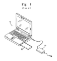
- Fig.1 is a schematic perspective view of a portable computer system 10.
- the computer system 10 is powered by either a smart rechargeable battery pack 20 or an AC-to-DC adapter 30.
- Smart batteries normally include memory storage devices which contain information regarding their characteristics and types.
- Some smart battery packs each include a microcontroller which allows communication by way of a bi-directional communication line with the battery charger regarding various battery characteristics.
- Such smart batteries are disclosed in, for example "Smart battery Specifications" by Duracell Inc. and Intel Corporation.
- Some smart batteries incorporate "fuel gauge” functions, by which the charge levels of the batteries can be indicated.
- An example of rechargeable batteries with such fuel gauge functions is described in U.S. Pat. No. 5,315,228.
- the prior art rechargeable battery measures its discharge current, estimates its self-discharge, and predicts its remaining capacity.
- the typical fuel gauge approach simply uses a recent value for average current consumption to calculate the remaining run time of the system. This may provide inaccurate information on the remaining capacity of the battery. If, for example, the remaining run time of the system reported from the fuel gauge is shorter than its actual run time, then the user cannot consume its full battery capacity. Alternatively, if the remaining run time of the system reported from the fuel gauge is longer than its actual run time, the portable computer system 10 will be shut down before the calculated run time.
- a battery calibration Prior to calibration, a battery must be fully charged. The fully charged battery is fully discharged to determine the exact battery capacity.
- the calibration of a battery takes a long time (ie, about 2-3 hours) because of the lengthy discharging time. Considering the total time for the calibrating process, the discharging process occupies the majority of the total time. In order to reduce the calibration time of a battery, faster discharging is desirable.
- a method of calibrating a capacity of a rechargeable battery for providing power for an electronic system such as a portable electronic system comprising the steps of:
- the high power consumption mode is a maximum power consumption mode.
- the method includes the step of setting the system to a low power consumption mode.
- the power consumption mode is a minimum power consumption mode.
- the rechargeable battery is a smart battery which has a microcontroller and one or more storage devices therein.
- the portable system includes a power management function.
- the method comprises the steps of disabling the power management function before said determining step, and/or enabling the power management function after said determining step.
- the electronic system is a portable computer.
- the electronic system includes system memories and/or and LCD device and/or a cooling fan and/or a HDD drive motor and/or a FDD drive motor.
- said system memories are repeatedly accessed and/or said cooling fan and/or said HDD and/or said FDD drive motor are driven at their maximum speed.
- the present invention aims to provide a faster calibration method for rechargeable batteries used particularly for portable electronic systems.
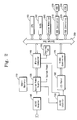
- Fig.2 is a block diagram which illustrates a portable computer system powered from a smart battery according to an embodiment of the present invention.
- the portable computer system comprises an AC-to-DC adapter 100, a smart rechargeable battery 110 including an embedded microncontroller (not shown) and embedded storage devices (not shown), and a system power supply 120 which generates various system powers by using a power from the AC-to-DC adapter 100 or the battery 110.
- the system power supply 120 is coupled to a DC/AC inverter 130 and a microcomputer 140, respectively.
- the microcomputer 140 is coupled to the DC/AC inverter 130, a cooling fan 150, and a system bus 250.
- a central processing unit (CPU) 180, a basic input/output system (BIOS) 190, one or more system memories 200, and a video controller 170 are commonly coupled to the system bus 250.
- a flat panel display 160 such as a liquid crystal display (LCD) panel, is coupled between the DC/AC inverter 130 and the video controller 170.
- a hard disk drive (HDD) 230 and a floppy disk drive (FDD) 240 are coupled to the system bus 250 through an HDD controller 210 and an FDD controller 220, respectively.
- HDD hard disk drive
- FDD floppy disk drive
- the BIOS 190 contains a control logic for calibrating a capacity of the smart battery 110 according to the present invention.
- a calibration mode for a calibrating process is selected in a system setup (usually called CMOS setup) program.
- the microcomputer 140 controls charging/discharging operations of the rechargeable battery 110 by generating a plurality of control signals.
- the microcomputer 140 set the portable computer system to consume a maximum power for fast discharging of the battery 110.
- the system memories 200 are repeatedly accessed, the LCD panel 160 is driven to have a maximum brightness, the cooling fan 150, motors of the HDD and the FDD driver 230, 240 are driven at their maximum speed by the control signals from the microcomputer 140.
- discharging of the smart battery is performed rapidly during the calibration.
- the calibrating process can be performed rapidly.
- calibrating the capacity of the smart battery 110 is carried out after the battery 110 has been fully charged. Further, the calibration is executed when removal of the AC-to-DC adapter 100 from the system is ensured. Accordingly, although a user selects the battery calibration mode, the mode will not be entered unless the battery 110 is fully charged and the AC-to-DC adapter 100 is removed. This calibration process will be described in detail below with reference to figures of accompanying drawings.
- Fig 3A and Fig 3B are flowcharts illustrating a calibration method of a smart rechargeable battery according to the present invention. The steps of the flowcharts are performed by the microcomputer 140 and the smart battery 110.
- step S210 it is determined whether the smart battery calibration mode is selected by use of the system setup program. If so, control flow proceeds to the next query step S220 wherein it is asked whether the smart battery 110 is fully charged. If so, flow proceeds to step S240, but if not, flow proceeds to step S240 through step S230 in which the smart battery 110 is fully charged.
- step S240 a message for removing the AC-to-DC adapter 100 is displayed to the LCD panel 160, then flow advanced to step S250. Also optionally although preferably in step S250, it is verified whether the AC-to-DC adapter 100 is removed. If so, flow continues to step S260.
- step S260 the power management function is disabled for the beginning of actual calibrating process.
- step S270 the microcomputer 140 sets the portable computer system to its maximum power consumption mode.
- step S280 the smart battery 110 begins to be discharged.
- step S290 it is determined after a predetermined time (and repeatedly after a further predetermined time) whether the smart battery is fully discharged to a battery capacity learning level. If so, the flow continues to step S300, wherein the smart battery 110 learns its capacity to obtain its correct capacity value.
- step S310 the microcomputer 140 set the portable computer system to its minimum power consumption mode.
- step S320 the power management function is enabled and the calibrating process is terminated.
- the disparity between the predicted run time and the actual run time is calibrated through the foregoing calibrating process of the smart battery 110. Furthermore, the calibration is performed rapidly by the fast discharging of the smart battery under the maximum power consumption.
- a smart battery which provides electrical power and which reports the remaining capacity of the battery. Any disparity between the calculated remaining capacity and the actual capacity of the smart battery is calibrated through use of a maximum power consumption mode during calibration.
Abstract

Description
- The present invention relates to battery-powered electronic devices and, more particularly, to a method of calibrating capacities of rechargeable batteries.
- Rechargeable batteries are used in many of today's portable electronic devices, such as computers, camcorders and mobile phones, which are also capable of utilizing alternating current (AC) power. Battery power is utilized when AC power is not convenient or is not available.
- Various types of rechargeable batteries are known to be used in such applications. For example, nickel-cadium (NiCad), nickel metal hydride (NiMH), and lithium ion batteries are used.
- Fig.1 is a schematic perspective view of a
portable computer system 10. Referring to Fig. 1, thecomputer system 10 is powered by either a smartrechargeable battery pack 20 or an AC-to-DC adapter 30. Smart batteries normally include memory storage devices which contain information regarding their characteristics and types. Some smart battery packs each include a microcontroller which allows communication by way of a bi-directional communication line with the battery charger regarding various battery characteristics. Such smart batteries are disclosed in, for example "Smart battery Specifications" by Duracell Inc. and Intel Corporation. - With respect to the smart batteries, it is important to provide accurate information regarding the remaining capacities of the batteries. Some smart batteries incorporate "fuel gauge" functions, by which the charge levels of the batteries can be indicated. An example of rechargeable batteries with such fuel gauge functions is described in U.S. Pat. No. 5,315,228. The prior art rechargeable battery measures its discharge current, estimates its self-discharge, and predicts its remaining capacity.
- In most portable computers, a power management system's prediction of run time remaining and a user's actual run time do not correspond. This disparity may broaden when usage patterns vary widely.
- The typical fuel gauge approach simply uses a recent value for average current consumption to calculate the remaining run time of the system. This may provide inaccurate information on the remaining capacity of the battery. If, for example, the remaining run time of the system reported from the fuel gauge is shorter than its actual run time, then the user cannot consume its full battery capacity. Alternatively, if the remaining run time of the system reported from the fuel gauge is longer than its actual run time, the
portable computer system 10 will be shut down before the calculated run time. - One solution to the foregoing problem is to correct the graduations of the battery capacity, which is usually called a "battery calibration". Prior to calibration, a battery must be fully charged. The fully charged battery is fully discharged to determine the exact battery capacity. However, the calibration of a battery takes a long time (ie, about 2-3 hours) because of the lengthy discharging time. Considering the total time for the calibrating process, the discharging process occupies the majority of the total time. In order to reduce the calibration time of a battery, faster discharging is desirable.
- According to the invention there is provided a method of calibrating a capacity of a rechargeable battery for providing power for an electronic system such as a portable electronic system, the method comprising the steps of:
- setting the system to a high power consumption mode;
- discharging the rechargeable battery;
- determining the capacity of the rechargeable battery.
-
- Preferably, the high power consumption mode is a maximum power consumption mode.
- Preferably, the method includes the step of setting the system to a low power consumption mode.
- Preferably, the power consumption mode is a minimum power consumption mode.
- Preferably, the rechargeable battery is a smart battery which has a microcontroller and one or more storage devices therein.
- Preferably, the portable system includes a power management function.
- Preferably, the method comprises the steps of disabling the power management function before said determining step, and/or enabling the power management function after said determining step.
- Preferably, the electronic system is a portable computer.
- Preferably, the electronic system includes system memories and/or and LCD device and/or a cooling fan and/or a HDD drive motor and/or a FDD drive motor.
- Preferably, during the high power consumption mode, said system memories are repeatedly accessed and/or said cooling fan and/or said HDD and/or said FDD drive motor are driven at their maximum speed.
- Thus, the present invention aims to provide a faster calibration method for rechargeable batteries used particularly for portable electronic systems.
- The invention will now be described by way of example only with reference to the following drawings.
- Fig.1 is a schematic perspective view illustrating a conventional portable computer system;
- Fig.2 is a block diagram illustrating a portable computer system powered from a smart battery according to an embodiment of the present invention; and
- Fig.3A and Fig.3B are flowcharts illustrating a calibration method of a rechargeable battery according to the present invention.
-
- Fig.2 is a block diagram which illustrates a portable computer system powered from a smart battery according to an embodiment of the present invention.
- Referring to Fig.2, the portable computer system comprises an AC-to-
DC adapter 100, a smartrechargeable battery 110 including an embedded microncontroller (not shown) and embedded storage devices (not shown), and asystem power supply 120 which generates various system powers by using a power from the AC-to-DC adapter 100 or thebattery 110. Thesystem power supply 120 is coupled to a DC/AC inverter 130 and amicrocomputer 140, respectively. Themicrocomputer 140 is coupled to the DC/AC inverter 130, acooling fan 150, and asystem bus 250. A central processing unit (CPU) 180, a basic input/output system (BIOS) 190, one ormore system memories 200, and avideo controller 170 are commonly coupled to thesystem bus 250. Aflat panel display 160, such as a liquid crystal display (LCD) panel, is coupled between the DC/AC inverter 130 and thevideo controller 170. In addition, a hard disk drive (HDD) 230 and a floppy disk drive (FDD) 240 are coupled to thesystem bus 250 through anHDD controller 210 and anFDD controller 220, respectively. - The
BIOS 190 contains a control logic for calibrating a capacity of thesmart battery 110 according to the present invention. A calibration mode for a calibrating process is selected in a system setup (usually called CMOS setup) program. - During the calibrating process, the
microcomputer 140 controls charging/discharging operations of therechargeable battery 110 by generating a plurality of control signals. In particular, themicrocomputer 140 set the portable computer system to consume a maximum power for fast discharging of thebattery 110. - For example, during the maximum power consumption mode, the
system memories 200 are repeatedly accessed, theLCD panel 160 is driven to have a maximum brightness, thecooling fan 150, motors of the HDD and the FDDdriver microcomputer 140. Thus, discharging of the smart battery is performed rapidly during the calibration. As a result, the calibrating process can be performed rapidly. - Generally, calibrating the capacity of the
smart battery 110 is carried out after thebattery 110 has been fully charged. Further, the calibration is executed when removal of the AC-to-DC adapter 100 from the system is ensured. Accordingly, although a user selects the battery calibration mode, the mode will not be entered unless thebattery 110 is fully charged and the AC-to-DC adapter 100 is removed. This calibration process will be described in detail below with reference to figures of accompanying drawings. - Fig 3A and Fig 3B are flowcharts illustrating a calibration method of a smart rechargeable battery according to the present invention. The steps of the flowcharts are performed by the
microcomputer 140 and thesmart battery 110. - Referring to Fig 3A and Fig 3B at step S210, it is determined whether the smart battery calibration mode is selected by use of the system setup program. If so, control flow proceeds to the next query step S220 wherein it is asked whether the
smart battery 110 is fully charged. If so, flow proceeds to step S240, but if not, flow proceeds to step S240 through step S230 in which thesmart battery 110 is fully charged. Optionally, although preferably at step S240, a message for removing the AC-to-DC adapter 100 is displayed to theLCD panel 160, then flow advanced to step S250. Also optionally although preferably in step S250, it is verified whether the AC-to-DC adapter 100 is removed. If so, flow continues to step S260. At step S260, the power management function is disabled for the beginning of actual calibrating process. In step S270, themicrocomputer 140 sets the portable computer system to its maximum power consumption mode. In step S280, thesmart battery 110 begins to be discharged. Next in step S290, it is determined after a predetermined time (and repeatedly after a further predetermined time) whether the smart battery is fully discharged to a battery capacity learning level. If so, the flow continues to step S300, wherein thesmart battery 110 learns its capacity to obtain its correct capacity value. In step S310, themicrocomputer 140 set the portable computer system to its minimum power consumption mode. In step S320, the power management function is enabled and the calibrating process is terminated. - After the calibration of the smart battery capacity, when the user connects the
AC adapter 100 to the portable computer system, the dischargedsmart battery 110 is fully charged. - As described above, the disparity between the predicted run time and the actual run time is calibrated through the foregoing calibrating process of the
smart battery 110. Furthermore, the calibration is performed rapidly by the fast discharging of the smart battery under the maximum power consumption. - A smart battery is described which provides electrical power and which reports the remaining capacity of the battery. Any disparity between the calculated remaining capacity and the actual capacity of the smart battery is calibrated through use of a maximum power consumption mode during calibration.
- While the invention has been described in terms of an exemplary embodiment, it is contemplated that it may be practiced as outlined above with modifications within the spirit and scope of the appended claims.
Claims (11)
- A method of calibrating a capacity of a rechargeable battery for providing power for an electronic system, such as a portable electronic system, the method comprising the steps of:setting the system to a high power consumption mode;discharging the rechargeable battery;determining the capacity of the rechargeable battery.
- A method according to claim 1 in which the high power consumption mode is a maximum power consumption mode.
- A method according to claim 1 or 2 including the step:setting the system to a low power consumption mode.
- A method according to claim 3, in which the low power consumption mode is a minimum power consumption mode.
- A method according to any preceding claim in which the rechargeable battery is a smart battery which has a microcontroller and one or more storage devices therein.
- A method according to any preceding claim in which the portable system includes a power management function.
- A method according to claim 6, further comprising the steps of disabling the power management function before said determining step, and/or enabling the power management function after said determining step.
- A method according to any preceding claim in which the electronic system is a portable computer.
- A method according to any preceding claim in which the electronic system includes system memories and/or an LCD device and/or a cooling fan and/or a HDD drive motor and/or a FDD drive motor.
- A method according to claim 9 in which during the high power consumption mode, said system memories are repeatedly accessed and/or said LCD device is driven to have a maximum brightness and/or said cooling fan and/or said HDD and/or said FDD drive motor are driven at their maximum speed.
- A method as described herein with reference to figures 2, 3A and 3B.
Applications Claiming Priority (2)
| Application Number | Priority Date | Filing Date | Title |
|---|---|---|---|
| KR1019980022436A KR100333771B1 (en) | 1998-06-15 | 1998-06-15 | A method of calibrating rechargeable battery capacity |
| KR9822436 | 1998-06-15 |
Publications (2)
| Publication Number | Publication Date |
|---|---|
| EP0965906A2 true EP0965906A2 (en) | 1999-12-22 |
| EP0965906A3 EP0965906A3 (en) | 2000-11-02 |
Family
ID=19539579
Family Applications (1)
| Application Number | Title | Priority Date | Filing Date |
|---|---|---|---|
| EP99304653A Ceased EP0965906A3 (en) | 1998-06-15 | 1999-06-15 | Calibrating rechargeable battery |
Country Status (6)
| Country | Link |
|---|---|
| US (1) | US6100666A (en) |
| EP (1) | EP0965906A3 (en) |
| JP (1) | JP2000060020A (en) |
| KR (1) | KR100333771B1 (en) |
| CN (1) | CN1138985C (en) |
| TW (1) | TW432767B (en) |
Cited By (3)
| Publication number | Priority date | Publication date | Assignee | Title |
|---|---|---|---|---|
| US6630814B2 (en) | 2000-12-19 | 2003-10-07 | Telefonaktiebolaget Lm Ericsson (Publ) | Method and apparatus for calibrating a rechargeable battery |
| EP2717422A1 (en) * | 2011-06-03 | 2014-04-09 | Sanyo Electric Co., Ltd | Assembled cell control system and power supply system comprising same |
| US9306243B2 (en) | 2011-01-24 | 2016-04-05 | International Business Machines Corporation | Optimizing battery usage |
Families Citing this family (16)
| Publication number | Priority date | Publication date | Assignee | Title |
|---|---|---|---|---|
| JP2001331242A (en) * | 2000-05-22 | 2001-11-30 | Hitachi Ltd | Information processor and method for controlling its power consumption |
| JP4777507B2 (en) * | 2000-09-18 | 2011-09-21 | 富士通株式会社 | Electronic equipment and processing capacity change instruction device |
| JP3692089B2 (en) * | 2002-04-02 | 2005-09-07 | 株式会社東芝 | Power consumption control method and information processing apparatus |
| KR20040013608A (en) * | 2002-08-07 | 2004-02-14 | 삼성전자주식회사 | Portable computer and controlling method thereof |
| TW556421B (en) | 2002-08-15 | 2003-10-01 | Htc Corp | Circuit and operating method for integrated interface of PDA and wireless communication system |
| US6892148B2 (en) * | 2002-12-29 | 2005-05-10 | Texas Instruments Incorporated | Circuit and method for measurement of battery capacity fade |
| US20060075509A1 (en) * | 2003-05-22 | 2006-04-06 | Jakob Kishon | Data storage protection device |
| WO2009007885A1 (en) * | 2007-07-09 | 2009-01-15 | Koninklijke Philips Electronics N.V. | Method and device for determining the state of charge of a battery |
| JP5570782B2 (en) * | 2009-10-16 | 2014-08-13 | 三洋電機株式会社 | POWER SUPPLY DEVICE, VEHICLE EQUIPPED WITH THE SAME, AND CHARGING / DISCHARGE CONTROL METHOD FOR POWER SUPPLY DEVICE |
| US8443212B2 (en) * | 2009-12-18 | 2013-05-14 | Hewlett-Packard Development Company, L.P. | Automated battery calibration |
| EP2593752B1 (en) * | 2010-07-13 | 2017-08-30 | TomTom International B.V. | A system and method for extending the physical life of batteries in mobile devices |
| JP5598914B2 (en) | 2010-08-05 | 2014-10-01 | 三洋電機株式会社 | Power supply system |
| JPWO2012133274A1 (en) | 2011-03-30 | 2014-07-28 | 三洋電機株式会社 | Power storage system and moving body |
| CN103499792B (en) * | 2013-07-18 | 2016-02-24 | 浙江工业大学 | The Forecasting Methodology of available capacity of EV power battery cluster |
| CN104597404B (en) * | 2014-12-19 | 2018-03-20 | 深圳市科陆电子科技股份有限公司 | The automatic calibration method of battery actual capacity, SOC and SOH |
| CN107132865B (en) * | 2017-04-07 | 2020-03-27 | 上海蔚来汽车有限公司 | Active cooling power calibration method and system for energy storage unit of test vehicle |
Family Cites Families (12)
| Publication number | Priority date | Publication date | Assignee | Title |
|---|---|---|---|---|
| US3969667A (en) * | 1972-08-23 | 1976-07-13 | The United States Of America As Represented By The Secretary Of The Navy | Device for determining the state of charge in batteries |
| JPS5337832A (en) * | 1976-09-20 | 1978-04-07 | Aichi Electric Mfg | Detecting device for residual capacity of storage battery |
| US4207611A (en) * | 1978-12-18 | 1980-06-10 | Ford Motor Company | Apparatus and method for calibrated testing of a vehicle electrical system |
| US4290002A (en) * | 1979-06-04 | 1981-09-15 | Gould Inc. | Method and apparatus for controlling battery recharging |
| GB8625035D0 (en) * | 1986-10-18 | 1986-11-19 | Husky Computers Ltd | Battery charge state monitor |
| US5140269A (en) * | 1990-09-10 | 1992-08-18 | Champlin Keith S | Electronic tester for assessing battery/cell capacity |
| US5563496A (en) * | 1990-12-11 | 1996-10-08 | Span, Inc. | Battery monitoring and charging control unit |
| US5268845A (en) * | 1991-02-14 | 1993-12-07 | Dell Corporate Services Corp. | Method for detecting low battery state without precise calibration |
| US5315228A (en) * | 1992-01-24 | 1994-05-24 | Compaq Computer Corp. | Battery charge monitor and fuel gauge |
| US5363689A (en) * | 1992-09-11 | 1994-11-15 | Intertech Development Company | Calibration device for leak detecting instruments |
| US5472056A (en) * | 1993-09-08 | 1995-12-05 | Case Corporation | Control system for agricultural vehicle and calibration method for such control systems |
| US5596260A (en) * | 1994-05-13 | 1997-01-21 | Apple Computer, Inc. | Apparatus and method for determining a charge of a battery |
-
1998
- 1998-06-15 KR KR1019980022436A patent/KR100333771B1/en not_active IP Right Cessation
-
1999
- 1999-05-11 TW TW088107585A patent/TW432767B/en not_active IP Right Cessation
- 1999-06-11 CN CNB991090098A patent/CN1138985C/en not_active Expired - Fee Related
- 1999-06-14 JP JP11167087A patent/JP2000060020A/en active Pending
- 1999-06-15 EP EP99304653A patent/EP0965906A3/en not_active Ceased
- 1999-06-15 US US09/333,262 patent/US6100666A/en not_active Expired - Lifetime
Non-Patent Citations (4)
| Title |
|---|
| "CHARGE AND DISCHARGE FUNCTION IN NOTEBOOK PC" IBM TECHNICAL DISCLOSURE BULLETIN,US,IBM CORP. NEW YORK, vol. 35, no. 4A, 1 September 1992 (1992-09-01), pages 477-480, XP000314842 ISSN: 0018-8689 * |
| DULEY R: "ARCHITECTURAL ASPECTS OF POWER MANAGEMENT AND BATTERY MANAGEMENT INPORTABLE SYSTEMS" WESCON CONFERENCE,US,IEEE CENTER, HOES LANE, 27 September 1994 (1994-09-27), pages 292-298, XP000532588 ISSN: 1044-6036 * |
| DULEY R: "DESIGNING A NOTEBOOK POWER SUPPLY ATTENTION TO DETAIL SPAWNS EFFICIENCY WHILE AVOIDING PROBLEMS LATER IN THE DESIGN CYCLE" ELECTRONIC DESIGN,US,PENTON PUBLISHING, CLEVELAND, OH, vol. 42, no. 15, 25 July 1994 (1994-07-25), pages 109-110,112,114,116,118-119, XP000444845 ISSN: 0013-4872 * |
| FREEMAN D: "FREEING PORTABLES FROM BATTERY TYRANNY" ELECTRONIC DESIGN,US,PENTON PUBLISHING, CLEVELAND, OH, vol. 43, no. 14, 10 July 1995 (1995-07-10), pages 115-118,120-121, XP000531693 ISSN: 0013-4872 * |
Cited By (5)
| Publication number | Priority date | Publication date | Assignee | Title |
|---|---|---|---|---|
| US6630814B2 (en) | 2000-12-19 | 2003-10-07 | Telefonaktiebolaget Lm Ericsson (Publ) | Method and apparatus for calibrating a rechargeable battery |
| US9306243B2 (en) | 2011-01-24 | 2016-04-05 | International Business Machines Corporation | Optimizing battery usage |
| EP2717422A1 (en) * | 2011-06-03 | 2014-04-09 | Sanyo Electric Co., Ltd | Assembled cell control system and power supply system comprising same |
| EP2717422A4 (en) * | 2011-06-03 | 2014-11-12 | Sanyo Electric Co | Assembled cell control system and power supply system comprising same |
| US9093864B2 (en) | 2011-06-03 | 2015-07-28 | Panasonic Intellectual Property Management Co., Ltd. | Assembled cell control system and power supply system comprising same |
Also Published As
| Publication number | Publication date |
|---|---|
| CN1138985C (en) | 2004-02-18 |
| KR20000001949A (en) | 2000-01-15 |
| US6100666A (en) | 2000-08-08 |
| CN1239226A (en) | 1999-12-22 |
| KR100333771B1 (en) | 2002-08-27 |
| EP0965906A3 (en) | 2000-11-02 |
| JP2000060020A (en) | 2000-02-25 |
| TW432767B (en) | 2001-05-01 |
Similar Documents
| Publication | Publication Date | Title |
|---|---|---|
| EP0965906A2 (en) | Calibrating rechargeable battery | |
| US6771042B2 (en) | Method and apparatus for implementing smart management of a rechargeable battery | |
| US5963010A (en) | Battery controller for controlling batteries of different kinds and including battery monitoring means for calculating remaining operation time and an information processing apparatus including such battery controller | |
| US6424123B1 (en) | Battery charging system and charge control apparatus | |
| US5565759A (en) | Smart battery providing battery life and recharge time prediction | |
| US5572110A (en) | Smart battery charger system | |
| US5541489A (en) | Smart battery power availability feature based on battery-specific characteristics | |
| US6664764B1 (en) | Apparatus and method for detecting a battery use state and mitigating battery deterioration | |
| US5600230A (en) | Smart battery providing programmable remaining capacity and run-time alarms based on battery-specific characteristics | |
| US6842708B2 (en) | Method and apparatus for determining battery life | |
| US6100670A (en) | Multi-functional battery management module operable in a charging mode and a battery pack mode | |
| JP3766500B2 (en) | Battery pack and computer system with battery pack | |
| US6194867B1 (en) | Adaptive multiple battery charging apparatus | |
| US6097175A (en) | Method for charging and discharging a smart battery of an electronic equipment | |
| US6294894B1 (en) | Rechargeable battery arrangement | |
| TW201008076A (en) | Intelligent battery charging rate management | |
| JPH08138749A (en) | Battery control method | |
| US6691049B1 (en) | Method and apparatus to detect that the battery gauge is out of calibration | |
| US5617008A (en) | Method, apparatus, and communication device for charging a charge storage device which is momentarily connected to a fixed load | |
| JP2000323182A (en) | Battery pack power source device | |
| JP2001051029A (en) | Charging battery or charging battery pack | |
| JP4178141B2 (en) | Charging apparatus and charging method | |
| JP2001051030A (en) | Charging battery or changing battery pack | |
| JPH0864254A (en) | Charging system for battery pack | |
| KR100694062B1 (en) | Apparatus and control method for charging multi-battery |
Legal Events
| Date | Code | Title | Description |
|---|---|---|---|
| PUAI | Public reference made under article 153(3) epc to a published international application that has entered the european phase |
Free format text: ORIGINAL CODE: 0009012 |
|
| 17P | Request for examination filed |
Effective date: 19990625 |
|
| AK | Designated contracting states |
Kind code of ref document: A2 Designated state(s): DE FR GB |
|
| AX | Request for extension of the european patent |
Free format text: AL;LT;LV;MK;RO;SI |
|
| PUAL | Search report despatched |
Free format text: ORIGINAL CODE: 0009013 |
|
| AK | Designated contracting states |
Kind code of ref document: A3 Designated state(s): AT BE CH CY DE DK ES FI FR GB GR IE IT LI LU MC NL PT SE |
|
| AX | Request for extension of the european patent |
Free format text: AL;LT;LV;MK;RO;SI |
|
| AKX | Designation fees paid |
Free format text: DE FR GB |
|
| 17Q | First examination report despatched |
Effective date: 20021219 |
|
| APBN | Date of receipt of notice of appeal recorded |
Free format text: ORIGINAL CODE: EPIDOSNNOA2E |
|
| APBR | Date of receipt of statement of grounds of appeal recorded |
Free format text: ORIGINAL CODE: EPIDOSNNOA3E |
|
| APAF | Appeal reference modified |
Free format text: ORIGINAL CODE: EPIDOSCREFNE |
|
| APAF | Appeal reference modified |
Free format text: ORIGINAL CODE: EPIDOSCREFNE |
|
| APBT | Appeal procedure closed |
Free format text: ORIGINAL CODE: EPIDOSNNOA9E |
|
| STAA | Information on the status of an ep patent application or granted ep patent |
Free format text: STATUS: THE APPLICATION HAS BEEN REFUSED |
|
| 18R | Application refused |
Effective date: 20090130 |