EP0951877A2 - A multi-laminate stent having superelastic articulated sections - Google Patents
A multi-laminate stent having superelastic articulated sections Download PDFInfo
- Publication number
- EP0951877A2 EP0951877A2 EP99303003A EP99303003A EP0951877A2 EP 0951877 A2 EP0951877 A2 EP 0951877A2 EP 99303003 A EP99303003 A EP 99303003A EP 99303003 A EP99303003 A EP 99303003A EP 0951877 A2 EP0951877 A2 EP 0951877A2
- Authority
- EP
- European Patent Office
- Prior art keywords
- stent
- graft
- plastically deformable
- layer
- superelastic
- Prior art date
- Legal status (The legal status is an assumption and is not a legal conclusion. Google has not performed a legal analysis and makes no representation as to the accuracy of the status listed.)
- Granted
Links
Images


Classifications
-
- A—HUMAN NECESSITIES
- A61—MEDICAL OR VETERINARY SCIENCE; HYGIENE
- A61F—FILTERS IMPLANTABLE INTO BLOOD VESSELS; PROSTHESES; DEVICES PROVIDING PATENCY TO, OR PREVENTING COLLAPSING OF, TUBULAR STRUCTURES OF THE BODY, e.g. STENTS; ORTHOPAEDIC, NURSING OR CONTRACEPTIVE DEVICES; FOMENTATION; TREATMENT OR PROTECTION OF EYES OR EARS; BANDAGES, DRESSINGS OR ABSORBENT PADS; FIRST-AID KITS
- A61F2/00—Filters implantable into blood vessels; Prostheses, i.e. artificial substitutes or replacements for parts of the body; Appliances for connecting them with the body; Devices providing patency to, or preventing collapsing of, tubular structures of the body, e.g. stents
- A61F2/82—Devices providing patency to, or preventing collapsing of, tubular structures of the body, e.g. stents
- A61F2/86—Stents in a form characterised by the wire-like elements; Stents in the form characterised by a net-like or mesh-like structure
- A61F2/90—Stents in a form characterised by the wire-like elements; Stents in the form characterised by a net-like or mesh-like structure characterised by a net-like or mesh-like structure
- A61F2/91—Stents in a form characterised by the wire-like elements; Stents in the form characterised by a net-like or mesh-like structure characterised by a net-like or mesh-like structure made from perforated sheet material or tubes, e.g. perforated by laser cuts or etched holes
- A61F2/915—Stents in a form characterised by the wire-like elements; Stents in the form characterised by a net-like or mesh-like structure characterised by a net-like or mesh-like structure made from perforated sheet material or tubes, e.g. perforated by laser cuts or etched holes with bands having a meander structure, adjacent bands being connected to each other
- A61F2002/91533—Stents in a form characterised by the wire-like elements; Stents in the form characterised by a net-like or mesh-like structure characterised by a net-like or mesh-like structure made from perforated sheet material or tubes, e.g. perforated by laser cuts or etched holes with bands having a meander structure, adjacent bands being connected to each other characterised by the phase between adjacent bands
- A61F2002/91541—Adjacent bands are arranged out of phase
-
- A—HUMAN NECESSITIES
- A61—MEDICAL OR VETERINARY SCIENCE; HYGIENE
- A61F—FILTERS IMPLANTABLE INTO BLOOD VESSELS; PROSTHESES; DEVICES PROVIDING PATENCY TO, OR PREVENTING COLLAPSING OF, TUBULAR STRUCTURES OF THE BODY, e.g. STENTS; ORTHOPAEDIC, NURSING OR CONTRACEPTIVE DEVICES; FOMENTATION; TREATMENT OR PROTECTION OF EYES OR EARS; BANDAGES, DRESSINGS OR ABSORBENT PADS; FIRST-AID KITS
- A61F2/00—Filters implantable into blood vessels; Prostheses, i.e. artificial substitutes or replacements for parts of the body; Appliances for connecting them with the body; Devices providing patency to, or preventing collapsing of, tubular structures of the body, e.g. stents
- A61F2/82—Devices providing patency to, or preventing collapsing of, tubular structures of the body, e.g. stents
- A61F2/86—Stents in a form characterised by the wire-like elements; Stents in the form characterised by a net-like or mesh-like structure
- A61F2/90—Stents in a form characterised by the wire-like elements; Stents in the form characterised by a net-like or mesh-like structure characterised by a net-like or mesh-like structure
- A61F2/91—Stents in a form characterised by the wire-like elements; Stents in the form characterised by a net-like or mesh-like structure characterised by a net-like or mesh-like structure made from perforated sheet material or tubes, e.g. perforated by laser cuts or etched holes
- A61F2/915—Stents in a form characterised by the wire-like elements; Stents in the form characterised by a net-like or mesh-like structure characterised by a net-like or mesh-like structure made from perforated sheet material or tubes, e.g. perforated by laser cuts or etched holes with bands having a meander structure, adjacent bands being connected to each other
- A61F2002/9155—Adjacent bands being connected to each other
- A61F2002/91558—Adjacent bands being connected to each other connected peak to peak
-
- A—HUMAN NECESSITIES
- A61—MEDICAL OR VETERINARY SCIENCE; HYGIENE
- A61F—FILTERS IMPLANTABLE INTO BLOOD VESSELS; PROSTHESES; DEVICES PROVIDING PATENCY TO, OR PREVENTING COLLAPSING OF, TUBULAR STRUCTURES OF THE BODY, e.g. STENTS; ORTHOPAEDIC, NURSING OR CONTRACEPTIVE DEVICES; FOMENTATION; TREATMENT OR PROTECTION OF EYES OR EARS; BANDAGES, DRESSINGS OR ABSORBENT PADS; FIRST-AID KITS
- A61F2210/00—Particular material properties of prostheses classified in groups A61F2/00 - A61F2/26 or A61F2/82 or A61F9/00 or A61F11/00 or subgroups thereof
- A61F2210/0076—Particular material properties of prostheses classified in groups A61F2/00 - A61F2/26 or A61F2/82 or A61F9/00 or A61F11/00 or subgroups thereof multilayered, e.g. laminated structures
-
- A—HUMAN NECESSITIES
- A61—MEDICAL OR VETERINARY SCIENCE; HYGIENE
- A61F—FILTERS IMPLANTABLE INTO BLOOD VESSELS; PROSTHESES; DEVICES PROVIDING PATENCY TO, OR PREVENTING COLLAPSING OF, TUBULAR STRUCTURES OF THE BODY, e.g. STENTS; ORTHOPAEDIC, NURSING OR CONTRACEPTIVE DEVICES; FOMENTATION; TREATMENT OR PROTECTION OF EYES OR EARS; BANDAGES, DRESSINGS OR ABSORBENT PADS; FIRST-AID KITS
- A61F2250/00—Special features of prostheses classified in groups A61F2/00 - A61F2/26 or A61F2/82 or A61F9/00 or A61F11/00 or subgroups thereof
- A61F2250/0014—Special features of prostheses classified in groups A61F2/00 - A61F2/26 or A61F2/82 or A61F9/00 or A61F11/00 or subgroups thereof having different values of a given property or geometrical feature, e.g. mechanical property or material property, at different locations within the same prosthesis
- A61F2250/0018—Special features of prostheses classified in groups A61F2/00 - A61F2/26 or A61F2/82 or A61F9/00 or A61F11/00 or subgroups thereof having different values of a given property or geometrical feature, e.g. mechanical property or material property, at different locations within the same prosthesis differing in elasticity, stiffness or compressibility
-
- A—HUMAN NECESSITIES
- A61—MEDICAL OR VETERINARY SCIENCE; HYGIENE
- A61F—FILTERS IMPLANTABLE INTO BLOOD VESSELS; PROSTHESES; DEVICES PROVIDING PATENCY TO, OR PREVENTING COLLAPSING OF, TUBULAR STRUCTURES OF THE BODY, e.g. STENTS; ORTHOPAEDIC, NURSING OR CONTRACEPTIVE DEVICES; FOMENTATION; TREATMENT OR PROTECTION OF EYES OR EARS; BANDAGES, DRESSINGS OR ABSORBENT PADS; FIRST-AID KITS
- A61F2250/00—Special features of prostheses classified in groups A61F2/00 - A61F2/26 or A61F2/82 or A61F9/00 or A61F11/00 or subgroups thereof
- A61F2250/0014—Special features of prostheses classified in groups A61F2/00 - A61F2/26 or A61F2/82 or A61F9/00 or A61F11/00 or subgroups thereof having different values of a given property or geometrical feature, e.g. mechanical property or material property, at different locations within the same prosthesis
- A61F2250/0029—Special features of prostheses classified in groups A61F2/00 - A61F2/26 or A61F2/82 or A61F9/00 or A61F11/00 or subgroups thereof having different values of a given property or geometrical feature, e.g. mechanical property or material property, at different locations within the same prosthesis differing in bending or flexure capacity
Definitions
- the present invention relates to an expandable intraluminal graft for use within a body passageway or duct and, more particularly, expandable intraluminal vascular grafts which are particularly useful for repairing blood vessels narrowed or occluded by diseased luminal grafts.
- Intraluminal endovascular grafting or stenting has been demonstrated to be an alternative to conventional vascular surgery.
- Intraluminal endovascular grafting involves the percutaneous insertion into a blood vessel of a tubular prosthetic graft or stent and its delivery via a catheter to the desired location within the vascular system.
- Advantages of this method over conventional vascular surgery include obviating the need for surgically exposing, incising, removing, replacing, or bypassing the defective blood vessel.
- Structures which have previously been used as intraluminal vascular grafts have included various types of stents which are expanded within a vessel by a balloon catheter such as the one described in U.S. Patent 5,304,197 issued to Pinchuk et al. on April 19, 1994, which is hereby incorporated herein by reference.
- stents include helical wound wires such as those described in U.S. Patent 5,019,090 issued to Pinchuk on May 28, 1991, which is hereby incorporated herein by reference, and stents formed by cutting slots into a metal tube, such as the one described in U.S. Patent 4,733,665 issued to Palmaz on March 29, 1988, which is hereby incorporated herein by reference.
- Nitinol nickel titanium alloy
- the prior art makes reference to the use of Nitinol which has shape memory and/or superelastic characteristics in medical devices which are designed to be inserted into a patient's body.
- the shape memory characteristics allow the devices to be deformed to facilitate their insertion into a body lumen or cavity and then be heated within the body so that the device returns to its original shape.
- Superelastic characteristics on the other hand generally allow the metal to be deformed and restrained in the deformed condition to facilitate the insertion of the medical device containing the metal into a patient's body, with such deformation causing the phase transformation. Once within the body lumen the restraint on the superelastic member can be removed, thereby reducing the stress therein so that the superelastic member can return to its original un-deformed shape by the transformation back to the original phase.
- Alloys having shape memory/superelastic characteristics generally have at least two phases. These phases are a martensite phase, which has a relatively low tensile strength and which is stable at relatively low temperatures, and an austenite phase, which has a relatively high tensile strength and which is stable at temperatures higher than the martensite phase.
- Shape memory characteristics are imparted to the alloy by heating the metal at a temperature above which the transformation from the martensite phase to the austenite phase is complete, i.e. a temperature above which the austenite phase is stable (the Af temperature).
- the shape of the metal during this heat treatment is the shape "remembered”.
- the heat treated metal is cooled to a temperature at which the martensite phase is stable, causing the austenite phase to transform to the martensite phase.
- the metal in the martensite phase is then plastically deformed, e.g. to facilitate the entry thereof into a patient's body.
- the specimen When stress is applied to a specimen of a metal such as Nitinol exhibiting superelastic characteristics at a temperature above which the austenite is stable (i.e. the temperature at which the transformation of martensite phase to the austenite phase is complete), the specimen deforms elastically until it reaches a particular stress level where the alloy then undergoes a stress-induced phase transformation from the austenite phase to the martensite phase. As the phase transformation proceeds, the alloy undergoes significant increases in strain but with little or no corresponding increases in stress. The strain increases while the stress remains essentially constant until the transformation of the austenite phase to the martensite phase is complete. Thereafter, further increase in stress are necessary to cause further deformation. The martensitic metal first deforms elastically upon the application of additional stress and then plastically with permanent residual deformation.
- a metal such as Nitinol exhibiting superelastic characteristics at a temperature above which the austenite is stable (i.e. the temperature at which the transformation of martensite phase to
- the martensitic specimen will elastically recover and transform back to the austenite phase.
- the reduction in stress first causes a decrease in strain.
- stress reduction reaches the level at which the martensite phase transforms back into the austenite phase
- the stress level in the specimen will remain essentially constant (but substantially less than the constant stress level at which the austenite transforms to the martensite) until the transformation back to the austenite phase is complete, i.e. there is significant recovery in strain with only negligible corresponding stress reduction.
- further stress reduction results in elastic strain reduction.
- the length of the body passageway which requires repair, as by the insertion of a stent, may present problems if the length of the required graft cannot negotiate the curves or bends of the body passageway through which the graft is passed by the catheter.
- it is necessary to support a length of tissue within a body passageway by a graft wherein the length of the required graft exceeds the length of a graft which can be readily delivered via a catheter to the desired location within the vascular system.
- Some grafts do not have the requisite ability to bend so as to negotiate the curves and bends present within the vascular system, particularly prostheses or grafts which are relatively rigid and resist bending with respect to their longitudinal axes.
- an articulated stent An example of an articulated stent is given in U.S. Patent 5,195,984 issued to Schatz on March 23, 1993, which is hereby incorporated herein by reference. Such a stent is particularly useful for critical body passageways, such as the left main coronary artery of a patient's heart.
- Schatz discloses a stent having a plurality of expandable and deformable individual intraluminal vascular grafts or stents wherein and adjacent grafts are flexibly connected by a single connector members.
- a stent for implantation into a vessel of a patient.
- the stent has at least two plastically deformable and expandable tubular graft members for expansion within a vessel.
- Each of the graft member has a first end, a second end, a wall section disposed therebetween and a lumen extending therethrough.
- the stent further includes at least one articulation connecting the first end of one of the graft members with the second end of the other graft member. Wherein the articulation is made from a superelastic material.
- Stent 10 is shown in its collapsed condition ready to be disposed on a balloon catheter for delivery and subsequent deployment into a vessel of a patient.
- Stent 10 includes at least two expandable grafts.
- Stent 10 is shown as having 3 expandable grafts 20, 30 and 40 each having a first end, 22, 32 and 42, and a second end, 24, 34 and 44, and a wall surface, 26, 36 and 46, disposed therebetween.
- the wall surface has a plurality of slots, for example 28, 38 and 48, formed therein.
- each graft is formed from a metal tube and the slots are cut therein, typically by laser cutting or photochemical maching. After the slots are cut therein, each graft comprises a plurality of loops 50, 60 and 70, wherein adjacent loops are connected by at least one strut 52, 62 and 72.
- Grafts 20 and 30 and 40 are connected together by at least one articulation 80, and grafts 30 and 40 are connected together by at least one articulation 90.
- the articulations connect a loop from one graft to a loop from another graft.
- the articulation does not connect one loop of one stent to a loop of another stent directly across it. In stead it connects the loops along a curved path which is angled with respect to the longitudinal axis of the stent running through the lumen.
- stent 10 is made from a multi laminate hollow tube, or hypotube as it is often referred to by those skilled in the art, having at least two layers, wherein one layer is made from a plastically deformable material, such as stainless steel or titanium, and the inner layer is made from a superelastic material such as Nitinol.
- Stent 10 preferably has a stainless steel outer layer 100 and a superelastic Nitinol layer 110. The stent could have more than two layers and still possess all the advantages of the present invention.
- the stent could be made of a superelastic material, such as Nitinol, sandwiched between two layers of a plastically deformable, such as stainless steel.
- the inner layer of stainless is preferably relatively thin so that the articulated sections remain elastic.
- the laminate hypotube may be manufactured by any number of processes known to those skilled in the art, as evidenced in U.S. Patent 5,858,566 issued on January 12, 1999.
- the hypotube may be produced by hot rolling a series of layers of material into laminate sheets.
- the hot rolling process may be optimized to ensure mechanical bonding between the layers and that the composite material has the necessary tensile strength.
- the laminate sheets may then be rolled up around a mandrel and seam welded to form a tube.
- the seam welded tube can then be drawn to final size.
- the second process for making the hypotube is to place multiple layers of tubes within each other around a core mandrel.
- the composite structure may then be drawn and heat treated using conventional wire drawing practices until the finished tube diameter meets the physical properties and dimensions required.
- a sacrificial ductile core mandrel is placed within the hypotube prior to the wire drawing process.
- the composite system is then drawn to finish dimensions and the core mandrel is removed. Removal of the mandrel is achieved by reducing the cross section of the mandrel. By solely pulling the mandrel, the diameter of the mandrel can be reduced sufficiently to be easily removed.
- the structure may be loaded onto a lathe type tool and the slots and articulations may be cut from this tube using, for example, a laser etching cutting tool, a water saw, or an electron discharge machine.
- a laser etching cutting tool such as by photochemically etching, are well known by those of ordinary skill the art.
- the present invention has an advantage in that after the stent design is cut from the tube, the articulations can then be processed so that the outer layer of stainless steel is removes from the articulations. Therefore, the articulations are now only made from the superelastic Nitinol material. This additional process is done by selective etching or laser scribing. After all etching and selective etching is complete, the tube may then be deburred by a procedure such as shot peening, abrasive tumbling, honing, electropolishing and electroetching.
- a stent having relatively rigid grafts connected by very flexible and shape recoverable articulations can be formed. This allows for a stent which is flexible enough to navigate through tortuous paths, but which is long enough to cover a relatively large target site within a vessel. As seen from Figure 4, the stent 10 often has to pass through tight curves.
- Figure 4 shows the stent 10 loaded onto a balloon catheter 120 and being navigated through a vessel 130. Because articulations 80 and 90 are made from a superelastic material, they make the stent more flexible so that it can better pass through tight curves such as the one shown here.
- the stent need not have the particular design shown in the figures. It could simply be a stent having a plastically deformable layer and an elastic layer, wherein the stent has elastic zones along its body where the plastically deformable layer has been removed. That is the stent could simply be a graft member having at least two layers wherein one of the layers comprises an elastic layer of material extending from end to end, and said other layer comprises a plastically deformable material covering only a predetermined portion of the elastic layer.
- the multilaminate stent described herein can also be used to make a crush recoverable balloon expandable stent of the type described in EP-A-0 839 506 which is hereby incorporated herein by reference.
- the wall thickness of the plastically deformable layer is targeted to plastically deform during deployment.
- the superelastic layer is targeted to accept a load greater than the lower plateau of the stress versus strain curve for the superelastic layer and less than the upper plateau of the stress versus strain curve for the superelastic layer.
- the radial outward force is controlled by the plastically deformable member (yield point on the stress versus strain curve) and the crush resistance is controlled by the superelastic member (upper plateau on the stress versus strain curve).
- This combination will develop a stent which is balloon catheter deliverable to a known stent diameter, crush resistant, and exhibits no chronic outward force.
Abstract
Description
- The present invention relates to an expandable intraluminal graft for use within a body passageway or duct and, more particularly, expandable intraluminal vascular grafts which are particularly useful for repairing blood vessels narrowed or occluded by diseased luminal grafts.
- Intraluminal endovascular grafting or stenting has been demonstrated to be an alternative to conventional vascular surgery. Intraluminal endovascular grafting involves the percutaneous insertion into a blood vessel of a tubular prosthetic graft or stent and its delivery via a catheter to the desired location within the vascular system. Advantages of this method over conventional vascular surgery include obviating the need for surgically exposing, incising, removing, replacing, or bypassing the defective blood vessel.
- Structures which have previously been used as intraluminal vascular grafts have included various types of stents which are expanded within a vessel by a balloon catheter such as the one described in U.S. Patent 5,304,197 issued to Pinchuk et al. on April 19, 1994, which is hereby incorporated herein by reference. Examples of different types of stents include helical wound wires such as those described in U.S. Patent 5,019,090 issued to Pinchuk on May 28, 1991, which is hereby incorporated herein by reference, and stents formed by cutting slots into a metal tube, such as the one described in U.S. Patent 4,733,665 issued to Palmaz on March 29, 1988, which is hereby incorporated herein by reference.
- Other types of stents include self expanding stents, typically made from a superelastic material, such as a nickel titanium alloy (Nitinol). The prior art makes reference to the use of Nitinol which has shape memory and/or superelastic characteristics in medical devices which are designed to be inserted into a patient's body. The shape memory characteristics allow the devices to be deformed to facilitate their insertion into a body lumen or cavity and then be heated within the body so that the device returns to its original shape. Superelastic characteristics on the other hand generally allow the metal to be deformed and restrained in the deformed condition to facilitate the insertion of the medical device containing the metal into a patient's body, with such deformation causing the phase transformation. Once within the body lumen the restraint on the superelastic member can be removed, thereby reducing the stress therein so that the superelastic member can return to its original un-deformed shape by the transformation back to the original phase.
- Alloys having shape memory/superelastic characteristics generally have at least two phases. These phases are a martensite phase, which has a relatively low tensile strength and which is stable at relatively low temperatures, and an austenite phase, which has a relatively high tensile strength and which is stable at temperatures higher than the martensite phase.
- Shape memory characteristics are imparted to the alloy by heating the metal at a temperature above which the transformation from the martensite phase to the austenite phase is complete, i.e. a temperature above which the austenite phase is stable (the Af temperature). The shape of the metal during this heat treatment is the shape "remembered". The heat treated metal is cooled to a temperature at which the martensite phase is stable, causing the austenite phase to transform to the martensite phase. The metal in the martensite phase is then plastically deformed, e.g. to facilitate the entry thereof into a patient's body. Subsequent heating of the deformed martensite phase to a temperature above the martensite to austenite transformation temperature causes the deformed martensite phase to transform to the austenite phase and during this phase transformation the metal reverts back to its original shape if unrestrained. If restrained, the metal will remain martensitic until the restraint is removed.
- Methods of using the shape memory characteristics of these alloys in medical devices intended to be placed within a patient's body present operational difficulties. For example, with shape memory alloys having a stable martensite temperature below body temperature, it is frequently difficult to maintain the temperature of the medical device containing such an alloy sufficiently below body temperature to prevent the transformation of the martensite phase to the austenite phase when the device was being inserted into a patient's body. With intravascular devices formed of shape memory alloys having martensite-to-austenite transformation temperatures well above body temperature, the devices can be introduced into a patient's body with little or no problem, but they must be heated to the martensite-to-austenite transformation temperature which is frequently high enough to cause tissue damage and very high levels of pain.
- When stress is applied to a specimen of a metal such as Nitinol exhibiting superelastic characteristics at a temperature above which the austenite is stable (i.e. the temperature at which the transformation of martensite phase to the austenite phase is complete), the specimen deforms elastically until it reaches a particular stress level where the alloy then undergoes a stress-induced phase transformation from the austenite phase to the martensite phase. As the phase transformation proceeds, the alloy undergoes significant increases in strain but with little or no corresponding increases in stress. The strain increases while the stress remains essentially constant until the transformation of the austenite phase to the martensite phase is complete. Thereafter, further increase in stress are necessary to cause further deformation. The martensitic metal first deforms elastically upon the application of additional stress and then plastically with permanent residual deformation.
- If the load on the specimen is removed before any permanent deformation has occurred, the martensitic specimen will elastically recover and transform back to the austenite phase. The reduction in stress first causes a decrease in strain. As stress reduction reaches the level at which the martensite phase transforms back into the austenite phase, the stress level in the specimen will remain essentially constant (but substantially less than the constant stress level at which the austenite transforms to the martensite) until the transformation back to the austenite phase is complete, i.e. there is significant recovery in strain with only negligible corresponding stress reduction. After the transformation back to austenite is complete, further stress reduction results in elastic strain reduction. This ability to incur significant strain at relatively constant stress upon the application of a load and to recover from the deformation upon the removal of the load is commonly referred to as superelasticity or pseudoelasticity. It is this property of the material which makes it useful in manufacturing tube cut self-expanding stents. The prior art makes reference to the use of metal alloys having superelastic characteristics in medical devices which are intended to be inserted or otherwise used within a patient's body. See for example, U.S. Pat. No. 4,665,905 (Jervis) and U.S. Pat. No. 4,925,445 (Sakamoto et al.).
- However, in general, the foregoing structures, both balloon expandable and self-expanding, have one major disadvantage in common. Insofar as these structures must be delivered to the desired location within a given body passageway in a collapsed state, in order to pass through the body passageway. While it is necessary for the expanded stent to have enough rigidity to maintain the integrity of the vessel it is implanted into, it also needs to have sufficient flexibility so that it can be navigated through tortuous vessels. For repairing blood vessels narrowed or occluded by disease, or repairing other body passageways, the length of the body passageway which requires repair, as by the insertion of a stent, may present problems if the length of the required graft cannot negotiate the curves or bends of the body passageway through which the graft is passed by the catheter. In other words, in many instances, it is necessary to support a length of tissue within a body passageway by a graft, wherein the length of the required graft exceeds the length of a graft which can be readily delivered via a catheter to the desired location within the vascular system. Some grafts do not have the requisite ability to bend so as to negotiate the curves and bends present within the vascular system, particularly prostheses or grafts which are relatively rigid and resist bending with respect to their longitudinal axes.
- Accordingly, one solution to this problem has been the development of an articulated stent. An example of an articulated stent is given in U.S. Patent 5,195,984 issued to Schatz on March 23, 1993, which is hereby incorporated herein by reference. Such a stent is particularly useful for critical body passageways, such as the left main coronary artery of a patient's heart. Schatz discloses a stent having a plurality of expandable and deformable individual intraluminal vascular grafts or stents wherein and adjacent grafts are flexibly connected by a single connector members.
- Recently, however, there has been a need to improve upon the stent disclosed in the Schatz reference. Specifically, it has been a desire to the technical community to make such a stent which is even more flexible, so that the stent can navigate tortuous vessels better than before. The present invention provides such a stent.
- In accordance with the present invention, there is provided a stent for implantation into a vessel of a patient. The stent has at least two plastically deformable and expandable tubular graft members for expansion within a vessel. Each of the graft member has a first end, a second end, a wall section disposed therebetween and a lumen extending therethrough. the stent further includes at least one articulation connecting the first end of one of the graft members with the second end of the other graft member. Wherein the articulation is made from a superelastic material.
- The foregoing and other aspects of the present invention will best be appreciated with reference to the detailed description of the invention in conjunction with the accompanying drawings, wherein:
- Figure 1 is a partial perspective view of a stent made in accordance with the present invention.
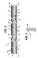
- Figure 2 is a side view of a stent made in accordance with the present invention.
- Figure 3 is a partial cross sectional view of the stent shown in Figure 2 taken along line 3-3.
- Figure 4 is a view similar to that of figure 2 but showing the stent as it would appear when navigating a body vessel.
-
- Referring now to the drawings in detail wherein like numerals indicate the same element throughout the views, there is shown in Figures 1 and 2 a
stent 10 made in accordance with the present invention.Stent 10 is shown in its collapsed condition ready to be disposed on a balloon catheter for delivery and subsequent deployment into a vessel of a patient.Stent 10 includes at least two expandable grafts.Stent 10 is shown as having 3expandable grafts loops strut -
Grafts articulation 80, andgrafts articulation 90. As seen from the figures, the articulations connect a loop from one graft to a loop from another graft. However, it is preferable that the articulation does not connect one loop of one stent to a loop of another stent directly across it. In stead it connects the loops along a curved path which is angled with respect to the longitudinal axis of the stent running through the lumen. - The particular design of the present stent and its advantages are best understood by describing the materials the stent is made from and how the slots and articulations are cut therefrom. By referring to Figure 3,
stent 10 is made from a multi laminate hollow tube, or hypotube as it is often referred to by those skilled in the art, having at least two layers, wherein one layer is made from a plastically deformable material, such as stainless steel or titanium, and the inner layer is made from a superelastic material such as Nitinol.Stent 10 preferably has a stainless steelouter layer 100 and asuperelastic Nitinol layer 110. The stent could have more than two layers and still possess all the advantages of the present invention. For example, the stent could be made of a superelastic material, such as Nitinol, sandwiched between two layers of a plastically deformable, such as stainless steel. The inner layer of stainless is preferably relatively thin so that the articulated sections remain elastic. - The laminate hypotube may be manufactured by any number of processes known to those skilled in the art, as evidenced in U.S. Patent 5,858,566 issued on January 12, 1999. In the first process the hypotube may be produced by hot rolling a series of layers of material into laminate sheets. The hot rolling process may be optimized to ensure mechanical bonding between the layers and that the composite material has the necessary tensile strength. The laminate sheets may then be rolled up around a mandrel and seam welded to form a tube. The seam welded tube can then be drawn to final size.
- The second process for making the hypotube is to place multiple layers of tubes within each other around a core mandrel. The composite structure may then be drawn and heat treated using conventional wire drawing practices until the finished tube diameter meets the physical properties and dimensions required. A sacrificial ductile core mandrel is placed within the hypotube prior to the wire drawing process. The composite system is then drawn to finish dimensions and the core mandrel is removed. Removal of the mandrel is achieved by reducing the cross section of the mandrel. By solely pulling the mandrel, the diameter of the mandrel can be reduced sufficiently to be easily removed.
- Once a composite hypotube is obtained, the structure may be loaded onto a lathe type tool and the slots and articulations may be cut from this tube using, for example, a laser etching cutting tool, a water saw, or an electron discharge machine. Other ways of cutting the slots, such as by photochemically etching, are well known by those of ordinary skill the art.
- The present invention has an advantage in that after the stent design is cut from the tube, the articulations can then be processed so that the outer layer of stainless steel is removes from the articulations. Therefore, the articulations are now only made from the superelastic Nitinol material. This additional process is done by selective etching or laser scribing. After all etching and selective etching is complete, the tube may then be deburred by a procedure such as shot peening, abrasive tumbling, honing, electropolishing and electroetching.
- By making the stent from a multi-laminate tube, wherein one layer is plastically deformable and the inner layer is superelastic, a stent having relatively rigid grafts connected by very flexible and shape recoverable articulations can be formed. This allows for a stent which is flexible enough to navigate through tortuous paths, but which is long enough to cover a relatively large target site within a vessel. As seen from Figure 4, the
stent 10 often has to pass through tight curves. Figure 4 shows thestent 10 loaded onto aballoon catheter 120 and being navigated through avessel 130. Becausearticulations - The multilaminate stent described herein can also be used to make a crush recoverable balloon expandable stent of the type described in EP-A-0 839 506 which is hereby incorporated herein by reference. By controlling the wall thickness of the plastically deformable layer relative to the superelastic section, the performance of the device can be adjusted. For this characteristic, the wall thickness of the plastically deformable layer is targeted to plastically deform during deployment. At the same load condition, the superelastic layer is targeted to accept a load greater than the lower plateau of the stress versus strain curve for the superelastic layer and less than the upper plateau of the stress versus strain curve for the superelastic layer. In this loading condition, the radial outward force is controlled by the plastically deformable member (yield point on the stress versus strain curve) and the crush resistance is controlled by the superelastic member (upper plateau on the stress versus strain curve). This combination will develop a stent which is balloon catheter deliverable to a known stent diameter, crush resistant, and exhibits no chronic outward force.
- Although particular embodiments of the present invention have been shown and described, modification may be made to the device and/or method without departing from the spirit and scope of the present invention. The terms used in describing the invention are used in their descriptive sense and not as terms of limitations.
Claims (11)
- A stent for implantation into a vessel of a patient, said stent comprising;a) at least two plastically deformable and expandable tubular graft members for expansion within a vessel, each said graft member having a first end, a second end, a wall section disposed therebetween and a lumen extending therethrough; andb) at least one articulation connecting the first end of one of said graft members with the second end of said other graft member, said articulation being made from a superelastic material.
- The stent of claim 1 wherein said at least one articulation comprises superelastic nickel titanium alloy.
- The stent of claim 1 or claim 2 wherein each said expandable graft comprises stainless steel.
- The stent of any one of claims 1 to 3 wherein said stent has a longitudinal axis extending through said lumens of said expandable grafts, and wherein said at least one articulation connects said graft members together along a curved line which is angled with respect to said longitudinal axis.
- The stent of any one of claims 1 to 4 wherein said graft members have at least two layers wherein one of said layers comprises a plastically deformable material, and said other layer comprises a superelastic material.
- The stent of claim 5 wherein said inner layer of said grafts is made from said superelastic material.
- A stent for implantation into a vessel of a patient, said stent comprising an expandable tubular graft member for expansion within a vessel, said graft member having a first end, a second end, a wall section disposed therebetween and a lumen extending therethrough, said graft member having at least two layers wherein one of said layers comprises an elastic layer of material extending from said first end to said second end, and said other layer comprises a plastically deformable material covering only a predetermined portion of said elastic layer.
- The stent of any one of claims 5 to 7 wherein each said plastically deformable layer of said expandable graft comprises stainless steel, and wherein said elastic layer of said expandable graft comprises a superelastic nickel and titanium alloy.
- The stent of any one of claims 1 to 8 wherein said graft member comprises a plurality of circumferential loops, wherein adjacent loops are connected together by at least one strut.
- A method for making a stent for expansion within a human vessel, said method comprising:a) forming a tubular member having an inner layer comprising a superelastic material and an outer layer comprising a plastically deformable material;b) removing portions of said inner and outer layers of said tube so as to form at least two plastically deformable and expandable tubular graft members connected together by at least one strut; andc) removing said outer plastically deformable layer from said at least one articulation.
- The method of claim 10 wherein said step of removing portions of said inner and outer layers of said tube so as to form at least two plastically deformable and expandable tubular graft members, comprises removing portions of said inner and outer layers and forming a plurality of circumferential loops and struts on each said graft, wherein adjacent loops are connected together by at least one strut.
Applications Claiming Priority (4)
| Application Number | Priority Date | Filing Date | Title |
|---|---|---|---|
| US8239798P | 1998-04-20 | 1998-04-20 | |
| US82397P | 1998-04-20 | ||
| US287036P | 1999-04-06 | ||
| US09/287,036 US6264687B1 (en) | 1998-04-20 | 1999-04-06 | Multi-laminate stent having superelastic articulated sections |
Publications (3)
| Publication Number | Publication Date |
|---|---|
| EP0951877A2 true EP0951877A2 (en) | 1999-10-27 |
| EP0951877A3 EP0951877A3 (en) | 2000-01-19 |
| EP0951877B1 EP0951877B1 (en) | 2004-06-23 |
Family
ID=26767408
Family Applications (1)
| Application Number | Title | Priority Date | Filing Date |
|---|---|---|---|
| EP99303003A Expired - Lifetime EP0951877B1 (en) | 1998-04-20 | 1999-04-19 | A multi-laminate stent having superelastic articulated sections |
Country Status (4)
| Country | Link |
|---|---|
| US (1) | US6264687B1 (en) |
| EP (1) | EP0951877B1 (en) |
| JP (1) | JP4209032B2 (en) |
| AU (1) | AU746217B2 (en) |
Cited By (24)
| Publication number | Priority date | Publication date | Assignee | Title |
|---|---|---|---|---|
| WO2000050100A1 (en) * | 1999-02-26 | 2000-08-31 | Advanced Cardiovascular Systems, Inc. | Composite super elastic/shape memory alloy and malleable alloy stent |
| WO2002043619A2 (en) * | 2000-11-28 | 2002-06-06 | Scimed Life Systems, Inc. | Method for manufacturing a medical device having a coated portion by laser ablation |
| EP1212986A1 (en) * | 2000-12-08 | 2002-06-12 | SORIN BIOMEDICA CARDIO S.p.A. | An angioplasty stent and manufacturing method thereof |
| WO2002034162A3 (en) * | 2000-10-20 | 2002-08-01 | Endotex Interventional Sys Inc | Selectively thinned coiled-sheet stents and methods for making them |
| WO2002036045A3 (en) * | 2000-10-31 | 2002-09-12 | Scimed Life Systems Inc | Endoluminal device having superelastic and plastically deformable sections |
| WO2004002369A1 (en) * | 2002-06-27 | 2004-01-08 | Boston Scientific Limited | Methods of making endoprostheses |
| WO2004078405A1 (en) * | 2003-02-27 | 2004-09-16 | Medtronic Vascular, Inc. | Method for manufacturing an endovascular support device using tumbling operation to round edges of the stent |
| WO2005025454A2 (en) * | 2003-09-10 | 2005-03-24 | Boston Scientific Limited | Composite medical devices |
| US6890350B1 (en) | 1999-07-28 | 2005-05-10 | Scimed Life Systems, Inc. | Combination self-expandable, balloon-expandable endoluminal device |
| WO2009089055A1 (en) * | 2008-01-11 | 2009-07-16 | Gore Enterprise Holdings, Inc. | Stent having adjacent elements connected by flexible webs |
| US8500794B2 (en) | 2007-08-02 | 2013-08-06 | Flexible Stenting Solutions, Inc. | Flexible stent |
| CN103857363A (en) * | 2011-10-03 | 2014-06-11 | 雅培心血管系统公司 | Modified scaffolds for peripheral applications |
| US9149376B2 (en) | 2008-10-06 | 2015-10-06 | Cordis Corporation | Reconstrainable stent delivery system |
| US9539120B2 (en) | 2008-10-10 | 2017-01-10 | Veryan Medical Ltd. | Medical device suitable for location in a body lumen |
| US9592137B2 (en) | 2005-04-04 | 2017-03-14 | Flexible Stenting Solutions, Inc. | Flexible stent |
| US9622888B2 (en) | 2006-11-16 | 2017-04-18 | W. L. Gore & Associates, Inc. | Stent having flexibly connected adjacent stent elements |
| US10117763B2 (en) | 2014-03-18 | 2018-11-06 | Boston Scientific Scimed, Inc. | Reduced granulation and inflammation stent design |
| CN109069261A (en) * | 2016-04-25 | 2018-12-21 | 美敦力瓦斯科尔勒公司 | interlayer prosthesis system and method |
| US10299948B2 (en) | 2014-11-26 | 2019-05-28 | W. L. Gore & Associates, Inc. | Balloon expandable endoprosthesis |
| US10456276B2 (en) | 2009-05-08 | 2019-10-29 | Veryan Medical Limited | Medical device suitable for location in a body lumen |
| US10568752B2 (en) | 2016-05-25 | 2020-02-25 | W. L. Gore & Associates, Inc. | Controlled endoprosthesis balloon expansion |
| CN111700712A (en) * | 2020-05-21 | 2020-09-25 | 普霖医疗科技(广州)有限公司 | Branch covered stent |
| CN111870392A (en) * | 2020-06-16 | 2020-11-03 | 普霖医疗科技(广州)有限公司 | Covered stent |
| US10966847B2 (en) | 2008-10-10 | 2021-04-06 | Veryan Medical Limited | Medical device suitable for location in a body lumen |
Families Citing this family (75)
| Publication number | Priority date | Publication date | Assignee | Title |
|---|---|---|---|---|
| US5938697A (en) * | 1998-03-04 | 1999-08-17 | Scimed Life Systems, Inc. | Stent having variable properties |
| US6620192B1 (en) * | 1999-03-16 | 2003-09-16 | Advanced Cardiovascular Systems, Inc. | Multilayer stent |
| US6425855B2 (en) * | 1999-04-06 | 2002-07-30 | Cordis Corporation | Method for making a multi-laminate stent having superelastic articulated sections |
| US6409754B1 (en) | 1999-07-02 | 2002-06-25 | Scimed Life Systems, Inc. | Flexible segmented stent |
| US6733513B2 (en) * | 1999-11-04 | 2004-05-11 | Advanced Bioprosthetic Surfaces, Ltd. | Balloon catheter having metal balloon and method of making same |
| US8458879B2 (en) | 2001-07-03 | 2013-06-11 | Advanced Bio Prosthetic Surfaces, Ltd., A Wholly Owned Subsidiary Of Palmaz Scientific, Inc. | Method of fabricating an implantable medical device |
| US6936066B2 (en) * | 1999-11-19 | 2005-08-30 | Advanced Bio Prosthetic Surfaces, Ltd. | Complaint implantable medical devices and methods of making same |
| US6379383B1 (en) | 1999-11-19 | 2002-04-30 | Advanced Bio Prosthetic Surfaces, Ltd. | Endoluminal device exhibiting improved endothelialization and method of manufacture thereof |
| US6953476B1 (en) * | 2000-03-27 | 2005-10-11 | Neovasc Medical Ltd. | Device and method for treating ischemic heart disease |
| US6315708B1 (en) * | 2000-03-31 | 2001-11-13 | Cordis Corporation | Stent with self-expanding end sections |
| US8845713B2 (en) | 2000-05-12 | 2014-09-30 | Advanced Bio Prosthetic Surfaces, Ltd., A Wholly Owned Subsidiary Of Palmaz Scientific, Inc. | Self-supporting laminated films, structural materials and medical devices manufactured therefrom and methods of making same |
| US6572646B1 (en) * | 2000-06-02 | 2003-06-03 | Advanced Cardiovascular Systems, Inc. | Curved nitinol stent for extremely tortuous anatomy |
| AU2002233936A1 (en) * | 2000-11-07 | 2002-05-21 | Advanced Bio Prosthetic Surfaces, Ltd. | Endoluminal stent, self-fupporting endoluminal graft and methods of making same |
| US8372139B2 (en) * | 2001-02-14 | 2013-02-12 | Advanced Bio Prosthetic Surfaces, Ltd. | In vivo sensor and method of making same |
| US6565599B1 (en) * | 2000-12-28 | 2003-05-20 | Advanced Cardiovascular Systems, Inc. | Hybrid stent |
| US7087088B2 (en) * | 2001-05-24 | 2006-08-08 | Torax Medical, Inc. | Methods and apparatus for regulating the flow of matter through body tubing |
| AU2002345328A1 (en) | 2001-06-27 | 2003-03-03 | Remon Medical Technologies Ltd. | Method and device for electrochemical formation of therapeutic species in vivo |
| US20030055485A1 (en) * | 2001-09-17 | 2003-03-20 | Intra Therapeutics, Inc. | Stent with offset cell geometry |
| DE60223886T2 (en) * | 2001-10-22 | 2008-11-06 | Terumo K.K. | STENT AND METHOD FOR THE PRODUCTION THEREOF |
| US6945994B2 (en) * | 2001-12-05 | 2005-09-20 | Boston Scientific Scimed, Inc. | Combined balloon-expanding and self-expanding stent |
| US20050197715A1 (en) * | 2002-04-26 | 2005-09-08 | Torax Medical, Inc. | Methods and apparatus for implanting devices into non-sterile body lumens or organs |
| US7695427B2 (en) * | 2002-04-26 | 2010-04-13 | Torax Medical, Inc. | Methods and apparatus for treating body tissue sphincters and the like |
| DE10233085B4 (en) | 2002-07-19 | 2014-02-20 | Dendron Gmbh | Stent with guide wire |
| US8425549B2 (en) | 2002-07-23 | 2013-04-23 | Reverse Medical Corporation | Systems and methods for removing obstructive matter from body lumens and treating vascular defects |
| MXPA05001845A (en) | 2002-08-15 | 2005-11-17 | Gmp Cardiac Care Inc | Stent-graft with rails. |
| AU2003270817B2 (en) | 2002-09-26 | 2009-09-17 | Vactronix Scientific, Llc | High strength vacuum deposited nitionol alloy films, medical thin film graft materials and method of making same |
| KR100485013B1 (en) * | 2002-10-22 | 2005-04-22 | 주식회사 에스앤지바이오텍 | A biodegradable stent and the manufacturing method thereof |
| US6923829B2 (en) * | 2002-11-25 | 2005-08-02 | Advanced Bio Prosthetic Surfaces, Ltd. | Implantable expandable medical devices having regions of differential mechanical properties and methods of making same |
| US6916409B1 (en) | 2002-12-31 | 2005-07-12 | Advanced Cardiovascular Systems, Inc. | Apparatus and process for electrolytic removal of material from a medical device |
| DE602004024053D1 (en) | 2003-05-07 | 2009-12-24 | Advanced Bio Prothestic Surfac | METALLIC IMPLANTABLE PROSTHESIS AND MANUFACTURING METHOD THEREFOR |
| US20050055080A1 (en) * | 2003-09-05 | 2005-03-10 | Naim Istephanous | Modulated stents and methods of making the stents |
| US8435280B2 (en) * | 2005-03-31 | 2013-05-07 | Boston Scientific Scimed, Inc. | Flexible stent with variable width elements |
| US20070061003A1 (en) * | 2005-09-15 | 2007-03-15 | Cappella, Inc. | Segmented ostial protection device |
| US8840660B2 (en) | 2006-01-05 | 2014-09-23 | Boston Scientific Scimed, Inc. | Bioerodible endoprostheses and methods of making the same |
| US8089029B2 (en) | 2006-02-01 | 2012-01-03 | Boston Scientific Scimed, Inc. | Bioabsorbable metal medical device and method of manufacture |
| US8048150B2 (en) | 2006-04-12 | 2011-11-01 | Boston Scientific Scimed, Inc. | Endoprosthesis having a fiber meshwork disposed thereon |
| US7651523B2 (en) | 2006-07-24 | 2010-01-26 | Cook Incorporated | Intraluminal device with flexible regions |
| EP2054537A2 (en) | 2006-08-02 | 2009-05-06 | Boston Scientific Scimed, Inc. | Endoprosthesis with three-dimensional disintegration control |
| JP2010503494A (en) | 2006-09-15 | 2010-02-04 | ボストン サイエンティフィック リミテッド | Biodegradable endoprosthesis and method for producing the same |
| WO2008034007A2 (en) * | 2006-09-15 | 2008-03-20 | Boston Scientific Limited | Medical devices |
| WO2008034048A2 (en) | 2006-09-15 | 2008-03-20 | Boston Scientific Limited | Bioerodible endoprosthesis with biostable inorganic layers |
| CA2663220A1 (en) | 2006-09-15 | 2008-03-20 | Boston Scientific Limited | Medical devices and methods of making the same |
| WO2008034031A2 (en) | 2006-09-15 | 2008-03-20 | Boston Scientific Limited | Bioerodible endoprostheses and methods of making the same |
| EP2068962B1 (en) | 2006-09-18 | 2013-01-30 | Boston Scientific Limited | Endoprostheses |
| US20080269774A1 (en) | 2006-10-26 | 2008-10-30 | Chestnut Medical Technologies, Inc. | Intracorporeal Grasping Device |
| ES2506144T3 (en) | 2006-12-28 | 2014-10-13 | Boston Scientific Limited | Bioerodible endoprosthesis and their manufacturing procedure |
| EP2144580B1 (en) * | 2007-04-09 | 2015-08-12 | Covidien LP | Stent delivery system |
| US8211162B2 (en) * | 2007-05-25 | 2012-07-03 | Boston Scientific Scimed, Inc. | Connector node for durable stent |
| JP5190836B2 (en) * | 2007-06-06 | 2013-04-24 | 国立大学法人山口大学 | Endoprosthesis |
| US8052745B2 (en) | 2007-09-13 | 2011-11-08 | Boston Scientific Scimed, Inc. | Endoprosthesis |
| US8088140B2 (en) | 2008-05-19 | 2012-01-03 | Mindframe, Inc. | Blood flow restorative and embolus removal methods |
| US11337714B2 (en) | 2007-10-17 | 2022-05-24 | Covidien Lp | Restoring blood flow and clot removal during acute ischemic stroke |
| AU2009217354B2 (en) | 2008-02-22 | 2013-10-10 | Covidien Lp | Methods and apparatus for flow restoration |
| US7998192B2 (en) | 2008-05-09 | 2011-08-16 | Boston Scientific Scimed, Inc. | Endoprostheses |
| US8236046B2 (en) | 2008-06-10 | 2012-08-07 | Boston Scientific Scimed, Inc. | Bioerodible endoprosthesis |
| US20100042202A1 (en) * | 2008-08-13 | 2010-02-18 | Kamal Ramzipoor | Composite stent having multi-axial flexibility |
| US8206635B2 (en) | 2008-06-20 | 2012-06-26 | Amaranth Medical Pte. | Stent fabrication via tubular casting processes |
| US10898620B2 (en) * | 2008-06-20 | 2021-01-26 | Razmodics Llc | Composite stent having multi-axial flexibility and method of manufacture thereof |
| US7985252B2 (en) | 2008-07-30 | 2011-07-26 | Boston Scientific Scimed, Inc. | Bioerodible endoprosthesis |
| US8382824B2 (en) | 2008-10-03 | 2013-02-26 | Boston Scientific Scimed, Inc. | Medical implant having NANO-crystal grains with barrier layers of metal nitrides or fluorides |
| WO2010101901A2 (en) | 2009-03-02 | 2010-09-10 | Boston Scientific Scimed, Inc. | Self-buffering medical implants |
| WO2010128311A1 (en) * | 2009-05-08 | 2010-11-11 | Veryan Medical Limited | A medical device suitable for location in a body lumen |
| EP2477583B1 (en) * | 2009-09-16 | 2015-04-08 | Bentley InnoMed GmbH | Stent having expandable elements |
| US8114149B2 (en) * | 2009-10-20 | 2012-02-14 | Svelte Medical Systems, Inc. | Hybrid stent with helical connectors |
| US8361140B2 (en) * | 2009-12-29 | 2013-01-29 | Boston Scientific Scimed, Inc. | High strength low opening pressure stent design |
| US20110160839A1 (en) * | 2009-12-29 | 2011-06-30 | Boston Scientific Scimed, Inc. | Endoprosthesis |
| US8668732B2 (en) | 2010-03-23 | 2014-03-11 | Boston Scientific Scimed, Inc. | Surface treated bioerodible metal endoprostheses |
| US8636811B2 (en) | 2010-04-07 | 2014-01-28 | Medtronic Vascular, Inc. | Drug eluting rolled stent and stent delivery system |
| US9039749B2 (en) | 2010-10-01 | 2015-05-26 | Covidien Lp | Methods and apparatuses for flow restoration and implanting members in the human body |
| KR101064215B1 (en) * | 2011-02-25 | 2011-09-14 | 강원대학교산학협력단 | Expandable stent |
| JP2012196499A (en) * | 2012-06-15 | 2012-10-18 | Yamaguchi Univ | Endoprosthesis |
| US10076399B2 (en) | 2013-09-13 | 2018-09-18 | Covidien Lp | Endovascular device engagement |
| EP4166073B1 (en) | 2019-02-04 | 2023-12-13 | Vactronix Scientific, LLC | Method of making an integrated circuit medical device |
| CN113208789B (en) * | 2021-03-30 | 2022-01-21 | 北京航空航天大学 | Vascular stent graft |
| CN115281905A (en) * | 2022-08-30 | 2022-11-04 | 苏州中天医疗器械科技有限公司 | Thrombectomy support, thrombectomy device and thrombectomy system |
Citations (6)
| Publication number | Priority date | Publication date | Assignee | Title |
|---|---|---|---|---|
| US4665905A (en) | 1986-06-09 | 1987-05-19 | Brown Charles S | Dynamic elbow and knee extension brace |
| US4733665A (en) | 1985-11-07 | 1988-03-29 | Expandable Grafts Partnership | Expandable intraluminal graft, and method and apparatus for implanting an expandable intraluminal graft |
| US4925445A (en) | 1983-09-16 | 1990-05-15 | Fuji Terumo Co., Ltd. | Guide wire for catheter |
| US5019090A (en) | 1988-09-01 | 1991-05-28 | Corvita Corporation | Radially expandable endoprosthesis and the like |
| US5195984A (en) | 1988-10-04 | 1993-03-23 | Expandable Grafts Partnership | Expandable intraluminal graft |
| US5304197A (en) | 1988-10-04 | 1994-04-19 | Cordis Corporation | Balloons for medical devices and fabrication thereof |
Family Cites Families (20)
| Publication number | Priority date | Publication date | Assignee | Title |
|---|---|---|---|---|
| US4403612A (en) | 1980-10-20 | 1983-09-13 | Fogarty Thomas J | Dilatation method |
| US5102417A (en) * | 1985-11-07 | 1992-04-07 | Expandable Grafts Partnership | Expandable intraluminal graft, and method and apparatus for implanting an expandable intraluminal graft |
| CA2380683C (en) * | 1991-10-28 | 2006-08-08 | Advanced Cardiovascular Systems, Inc. | Expandable stents and method for making same |
| FR2683449A1 (en) * | 1991-11-08 | 1993-05-14 | Cardon Alain | ENDOPROTHESIS FOR TRANSLUMINAL IMPLANTATION. |
| DE69313312T2 (en) | 1992-01-31 | 1998-01-02 | Advanced Cardiovascular System | Protective membrane for stent-carrying balloon catheters |
| US5383928A (en) | 1992-06-10 | 1995-01-24 | Emory University | Stent sheath for local drug delivery |
| US5507771A (en) | 1992-06-15 | 1996-04-16 | Cook Incorporated | Stent assembly |
| GR1002388B (en) | 1993-01-06 | 1996-07-03 | Ethicon Inc. | Stent. |
| US5480423A (en) | 1993-05-20 | 1996-01-02 | Boston Scientific Corporation | Prosthesis delivery |
| US5449373A (en) * | 1994-03-17 | 1995-09-12 | Medinol Ltd. | Articulated stent |
| US5554181A (en) | 1994-05-04 | 1996-09-10 | Regents Of The University Of Minnesota | Stent |
| EP0759730B1 (en) * | 1994-05-19 | 1999-02-10 | Scimed Life Systems, Inc. | Improved tissue supporting devices |
| DE69530891T2 (en) | 1994-06-27 | 2004-05-13 | Corvita Corp., Miami | Bistable luminal graft endoprostheses |
| US5662675A (en) * | 1995-02-24 | 1997-09-02 | Intervascular, Inc. | Delivery catheter assembly |
| US5858566A (en) | 1995-10-23 | 1999-01-12 | Seagate Technology, Inc. | Seeded underlayer in magnetic thin films |
| US5800512A (en) * | 1996-01-22 | 1998-09-01 | Meadox Medicals, Inc. | PTFE vascular graft |
| DE69738786D1 (en) | 1996-05-08 | 2008-07-31 | Sorin Biomedica Cardio Srl | A stent for angioplasty |
| US5928279A (en) * | 1996-07-03 | 1999-07-27 | Baxter International Inc. | Stented, radially expandable, tubular PTFE grafts |
| US6099561A (en) * | 1996-10-21 | 2000-08-08 | Inflow Dynamics, Inc. | Vascular and endoluminal stents with improved coatings |
| US6129755A (en) * | 1998-01-09 | 2000-10-10 | Nitinol Development Corporation | Intravascular stent having an improved strut configuration |
-
1999
- 1999-04-06 US US09/287,036 patent/US6264687B1/en not_active Expired - Lifetime
- 1999-04-19 JP JP11134899A patent/JP4209032B2/en not_active Expired - Lifetime
- 1999-04-19 EP EP99303003A patent/EP0951877B1/en not_active Expired - Lifetime
- 1999-04-19 AU AU23848/99A patent/AU746217B2/en not_active Ceased
Patent Citations (8)
| Publication number | Priority date | Publication date | Assignee | Title |
|---|---|---|---|---|
| US4925445A (en) | 1983-09-16 | 1990-05-15 | Fuji Terumo Co., Ltd. | Guide wire for catheter |
| US4733665A (en) | 1985-11-07 | 1988-03-29 | Expandable Grafts Partnership | Expandable intraluminal graft, and method and apparatus for implanting an expandable intraluminal graft |
| US4733665B1 (en) | 1985-11-07 | 1994-01-11 | Expandable Grafts Partnership | Expandable intraluminal graft,and method and apparatus for implanting an expandable intraluminal graft |
| US4733665C2 (en) | 1985-11-07 | 2002-01-29 | Expandable Grafts Partnership | Expandable intraluminal graft and method and apparatus for implanting an expandable intraluminal graft |
| US4665905A (en) | 1986-06-09 | 1987-05-19 | Brown Charles S | Dynamic elbow and knee extension brace |
| US5019090A (en) | 1988-09-01 | 1991-05-28 | Corvita Corporation | Radially expandable endoprosthesis and the like |
| US5195984A (en) | 1988-10-04 | 1993-03-23 | Expandable Grafts Partnership | Expandable intraluminal graft |
| US5304197A (en) | 1988-10-04 | 1994-04-19 | Cordis Corporation | Balloons for medical devices and fabrication thereof |
Cited By (45)
| Publication number | Priority date | Publication date | Assignee | Title |
|---|---|---|---|---|
| WO2000050100A1 (en) * | 1999-02-26 | 2000-08-31 | Advanced Cardiovascular Systems, Inc. | Composite super elastic/shape memory alloy and malleable alloy stent |
| US6890350B1 (en) | 1999-07-28 | 2005-05-10 | Scimed Life Systems, Inc. | Combination self-expandable, balloon-expandable endoluminal device |
| WO2002034162A3 (en) * | 2000-10-20 | 2002-08-01 | Endotex Interventional Sys Inc | Selectively thinned coiled-sheet stents and methods for making them |
| WO2002036045A3 (en) * | 2000-10-31 | 2002-09-12 | Scimed Life Systems Inc | Endoluminal device having superelastic and plastically deformable sections |
| WO2002043619A2 (en) * | 2000-11-28 | 2002-06-06 | Scimed Life Systems, Inc. | Method for manufacturing a medical device having a coated portion by laser ablation |
| US6517888B1 (en) | 2000-11-28 | 2003-02-11 | Scimed Life Systems, Inc. | Method for manufacturing a medical device having a coated portion by laser ablation |
| WO2002043619A3 (en) * | 2000-11-28 | 2003-02-13 | Scimed Life Systems Inc | Method for manufacturing a medical device having a coated portion by laser ablation |
| EP1616535A1 (en) * | 2000-11-28 | 2006-01-18 | Boston Scientific Scimed, Inc. | Method for manufacturing a medical device having a coated portion by laser ablation |
| EP1212986A1 (en) * | 2000-12-08 | 2002-06-12 | SORIN BIOMEDICA CARDIO S.p.A. | An angioplasty stent and manufacturing method thereof |
| WO2004002369A1 (en) * | 2002-06-27 | 2004-01-08 | Boston Scientific Limited | Methods of making endoprostheses |
| US6865810B2 (en) | 2002-06-27 | 2005-03-15 | Scimed Life Systems, Inc. | Methods of making medical devices |
| US6920677B2 (en) | 2003-02-27 | 2005-07-26 | Medtronic Vascular, Inc. | Method for manufacturing an endovascular support device |
| WO2004078405A1 (en) * | 2003-02-27 | 2004-09-16 | Medtronic Vascular, Inc. | Method for manufacturing an endovascular support device using tumbling operation to round edges of the stent |
| WO2005025454A2 (en) * | 2003-09-10 | 2005-03-24 | Boston Scientific Limited | Composite medical devices |
| WO2005025454A3 (en) * | 2003-09-10 | 2006-01-05 | Boston Scient Ltd | Composite medical devices |
| US9592137B2 (en) | 2005-04-04 | 2017-03-14 | Flexible Stenting Solutions, Inc. | Flexible stent |
| US10456281B2 (en) | 2006-11-16 | 2019-10-29 | W.L. Gore & Associates, Inc. | Stent having flexibly connected adjacent stent elements |
| US9622888B2 (en) | 2006-11-16 | 2017-04-18 | W. L. Gore & Associates, Inc. | Stent having flexibly connected adjacent stent elements |
| US8500794B2 (en) | 2007-08-02 | 2013-08-06 | Flexible Stenting Solutions, Inc. | Flexible stent |
| CN101909545B (en) * | 2008-01-11 | 2014-03-12 | 戈尔企业控股股份有限公司 | Stent having adjacent elements connected by flexible webs |
| CN103767805A (en) * | 2008-01-11 | 2014-05-07 | 戈尔企业控股股份有限公司 | Stent having adjacent elements connected by flexible webs |
| CN103784223A (en) * | 2008-01-11 | 2014-05-14 | 戈尔企业控股股份有限公司 | Stent having adjacent elements connected by flexible webs |
| US11865020B2 (en) | 2008-01-11 | 2024-01-09 | W. L. Gore & Associates, Inc. | Stent having adjacent elements connected by flexible webs |
| AU2009204460B2 (en) * | 2008-01-11 | 2013-02-07 | W. L. Gore & Associates, Inc. | Stent having adjacent elements connected by flexible webs |
| CN103767805B (en) * | 2008-01-11 | 2016-09-14 | W.L.戈尔及同仁股份有限公司 | Be there is the support of the adjacent elements being connected by flexible web |
| US11103372B2 (en) | 2008-01-11 | 2021-08-31 | W. L. Gore & Associates, Inc. | Stent having adjacent elements connected by flexible webs |
| WO2009089055A1 (en) * | 2008-01-11 | 2009-07-16 | Gore Enterprise Holdings, Inc. | Stent having adjacent elements connected by flexible webs |
| US9943428B2 (en) | 2008-01-11 | 2018-04-17 | W. L. Gore & Associates, Inc. | Stent having adjacent elements connected by flexible webs |
| US9149376B2 (en) | 2008-10-06 | 2015-10-06 | Cordis Corporation | Reconstrainable stent delivery system |
| US10010438B2 (en) | 2008-10-06 | 2018-07-03 | Flexible Stenting Solutions, Inc. | Reconstrainable stent delivery system |
| US10966847B2 (en) | 2008-10-10 | 2021-04-06 | Veryan Medical Limited | Medical device suitable for location in a body lumen |
| US9539120B2 (en) | 2008-10-10 | 2017-01-10 | Veryan Medical Ltd. | Medical device suitable for location in a body lumen |
| US10456276B2 (en) | 2009-05-08 | 2019-10-29 | Veryan Medical Limited | Medical device suitable for location in a body lumen |
| US11839558B2 (en) | 2009-05-08 | 2023-12-12 | Veryan Medical Limited | Medical device suitable for location in a body lumen |
| CN103857363A (en) * | 2011-10-03 | 2014-06-11 | 雅培心血管系统公司 | Modified scaffolds for peripheral applications |
| US10117763B2 (en) | 2014-03-18 | 2018-11-06 | Boston Scientific Scimed, Inc. | Reduced granulation and inflammation stent design |
| US10299948B2 (en) | 2014-11-26 | 2019-05-28 | W. L. Gore & Associates, Inc. | Balloon expandable endoprosthesis |
| US10543116B2 (en) | 2014-11-26 | 2020-01-28 | W. L. Gore & Associates, Inc. | Balloon expandable endoprosthesis |
| US11857444B2 (en) | 2014-11-26 | 2024-01-02 | W. L. Gore & Associates, Inc. | Balloon expandable endoprosthesis |
| US11285029B2 (en) | 2014-11-26 | 2022-03-29 | W. L. Gore & Associates, Inc. | Balloon expandable endoprosthesis |
| CN109069261A (en) * | 2016-04-25 | 2018-12-21 | 美敦力瓦斯科尔勒公司 | interlayer prosthesis system and method |
| US11779481B2 (en) | 2016-05-25 | 2023-10-10 | W. L. Gore & Associates, Inc. | Controlled endoprosthesis balloon expansion |
| US10568752B2 (en) | 2016-05-25 | 2020-02-25 | W. L. Gore & Associates, Inc. | Controlled endoprosthesis balloon expansion |
| CN111700712A (en) * | 2020-05-21 | 2020-09-25 | 普霖医疗科技(广州)有限公司 | Branch covered stent |
| CN111870392A (en) * | 2020-06-16 | 2020-11-03 | 普霖医疗科技(广州)有限公司 | Covered stent |
Also Published As
| Publication number | Publication date |
|---|---|
| EP0951877B1 (en) | 2004-06-23 |
| AU2384899A (en) | 1999-10-28 |
| JP4209032B2 (en) | 2009-01-14 |
| JPH11332998A (en) | 1999-12-07 |
| AU746217B2 (en) | 2002-04-18 |
| EP0951877A3 (en) | 2000-01-19 |
| US6264687B1 (en) | 2001-07-24 |
Similar Documents
| Publication | Publication Date | Title |
|---|---|---|
| EP0951877B1 (en) | A multi-laminate stent having superelastic articulated sections | |
| US6425855B2 (en) | Method for making a multi-laminate stent having superelastic articulated sections | |
| EP1242005B1 (en) | Stent designs for use in peripheral vessels | |
| US6296661B1 (en) | Self-expanding stent-graft | |
| EP1140244B2 (en) | Self-expanding prosthesis with biocompatible coating | |
| US6245100B1 (en) | Method for making a self-expanding stent-graft | |
| EP0928606B1 (en) | An intravascular stent having curved bridges for connecting adjacent hoops | |
| US6605110B2 (en) | Stent with enhanced bendability and flexibility | |
| US6129755A (en) | Intravascular stent having an improved strut configuration | |
| US8282679B2 (en) | Intravascular stents | |
| WO2001015632A1 (en) | Stent design with end rings having enhanced strength and radiopacity | |
| US8500791B2 (en) | Stent designs for use in peripheral vessels | |
| WO2008024928A2 (en) | Stent designs for use in peripheral vessels |
Legal Events
| Date | Code | Title | Description |
|---|---|---|---|
| PUAI | Public reference made under article 153(3) epc to a published international application that has entered the european phase |
Free format text: ORIGINAL CODE: 0009012 |
|
| AK | Designated contracting states |
Kind code of ref document: A2 Designated state(s): DE FR GB NL |
|
| AX | Request for extension of the european patent |
Free format text: AL;LT;LV;MK;RO;SI |
|
| PUAL | Search report despatched |
Free format text: ORIGINAL CODE: 0009013 |
|
| AK | Designated contracting states |
Kind code of ref document: A3 Designated state(s): AT BE CH CY DE DK ES FI FR GB GR IE IT LI LU MC NL PT SE |
|
| AX | Request for extension of the european patent |
Free format text: AL;LT;LV;MK;RO;SI |
|
| 17P | Request for examination filed |
Effective date: 20000626 |
|
| AKX | Designation fees paid |
Free format text: DE FR GB NL |
|
| 17Q | First examination report despatched |
Effective date: 20020808 |
|
| GRAP | Despatch of communication of intention to grant a patent |
Free format text: ORIGINAL CODE: EPIDOSNIGR1 |
|
| GRAS | Grant fee paid |
Free format text: ORIGINAL CODE: EPIDOSNIGR3 |
|
| GRAA | (expected) grant |
Free format text: ORIGINAL CODE: 0009210 |
|
| AK | Designated contracting states |
Kind code of ref document: B1 Designated state(s): DE FR GB NL |
|
| REG | Reference to a national code |
Ref country code: GB Ref legal event code: FG4D |
|
| REF | Corresponds to: |
Ref document number: 69918212 Country of ref document: DE Date of ref document: 20040729 Kind code of ref document: P |
|
| ET | Fr: translation filed | ||
| PLBE | No opposition filed within time limit |
Free format text: ORIGINAL CODE: 0009261 |
|
| STAA | Information on the status of an ep patent application or granted ep patent |
Free format text: STATUS: NO OPPOSITION FILED WITHIN TIME LIMIT |
|
| 26N | No opposition filed |
Effective date: 20050324 |
|
| REG | Reference to a national code |
Ref country code: FR Ref legal event code: PLFP Year of fee payment: 18 |
|
| PGFP | Annual fee paid to national office [announced via postgrant information from national office to epo] |
Ref country code: NL Payment date: 20160426 Year of fee payment: 18 |
|
| PGFP | Annual fee paid to national office [announced via postgrant information from national office to epo] |
Ref country code: GB Payment date: 20160427 Year of fee payment: 18 Ref country code: DE Payment date: 20160427 Year of fee payment: 18 |
|
| PGFP | Annual fee paid to national office [announced via postgrant information from national office to epo] |
Ref country code: FR Payment date: 20160425 Year of fee payment: 18 |
|
| REG | Reference to a national code |
Ref country code: DE Ref legal event code: R119 Ref document number: 69918212 Country of ref document: DE |
|
| REG | Reference to a national code |
Ref country code: NL Ref legal event code: MM Effective date: 20170501 |
|
| GBPC | Gb: european patent ceased through non-payment of renewal fee |
Effective date: 20170419 |
|
| REG | Reference to a national code |
Ref country code: FR Ref legal event code: ST Effective date: 20171229 |
|
| PG25 | Lapsed in a contracting state [announced via postgrant information from national office to epo] |
Ref country code: NL Free format text: LAPSE BECAUSE OF NON-PAYMENT OF DUE FEES Effective date: 20170501 Ref country code: DE Free format text: LAPSE BECAUSE OF NON-PAYMENT OF DUE FEES Effective date: 20171103 Ref country code: FR Free format text: LAPSE BECAUSE OF NON-PAYMENT OF DUE FEES Effective date: 20170502 |
|
| PG25 | Lapsed in a contracting state [announced via postgrant information from national office to epo] |
Ref country code: GB Free format text: LAPSE BECAUSE OF NON-PAYMENT OF DUE FEES Effective date: 20170419 |