EP0948111B1 - Fault protection arrangements and methods for electric power distribution systems - Google Patents
Fault protection arrangements and methods for electric power distribution systems Download PDFInfo
- Publication number
- EP0948111B1 EP0948111B1 EP99200880A EP99200880A EP0948111B1 EP 0948111 B1 EP0948111 B1 EP 0948111B1 EP 99200880 A EP99200880 A EP 99200880A EP 99200880 A EP99200880 A EP 99200880A EP 0948111 B1 EP0948111 B1 EP 0948111B1
- Authority
- EP
- European Patent Office
- Prior art keywords
- fault
- power source
- line
- circuit interruption
- interruption means
- Prior art date
- Legal status (The legal status is an assumption and is not a legal conclusion. Google has not performed a legal analysis and makes no representation as to the accuracy of the status listed.)
- Expired - Fee Related
Links
Images


Classifications
-
- H—ELECTRICITY
- H02—GENERATION; CONVERSION OR DISTRIBUTION OF ELECTRIC POWER
- H02H—EMERGENCY PROTECTIVE CIRCUIT ARRANGEMENTS
- H02H7/00—Emergency protective circuit arrangements specially adapted for specific types of electric machines or apparatus or for sectionalised protection of cable or line systems, and effecting automatic switching in the event of an undesired change from normal working conditions
- H02H7/26—Sectionalised protection of cable or line systems, e.g. for disconnecting a section on which a short-circuit, earth fault, or arc discharge has occured
- H02H7/30—Staggered disconnection
-
- H—ELECTRICITY
- H02—GENERATION; CONVERSION OR DISTRIBUTION OF ELECTRIC POWER
- H02H—EMERGENCY PROTECTIVE CIRCUIT ARRANGEMENTS
- H02H3/00—Emergency protective circuit arrangements for automatic disconnection directly responsive to an undesired change from normal electric working condition with or without subsequent reconnection ; integrated protection
- H02H3/02—Details
- H02H3/06—Details with automatic reconnection
- H02H3/063—Details concerning the co-operation of many similar arrangements, e.g. in a network
Definitions
- This invention relates to a fault protection arrangement and methods for fault protection in electric power distribution systems.
- JP 05091670 discloses buses that are interlinked through a semiconductor device for distributing power from a plurality of transformers. Distribution lines are provided from the buses that have respective fault detection sections. When the current exceeds a predetermined level with the semiconductor device on, a supervisory control section turns off the semiconductor device before a circuit breaker for each distribution line is turned off.
- a fault protection arrangement for an electric power distribution system comprising:
- the present invention provides automatic fault isolation and automatic system realignment more rapidly and with fewer components than prior art systems.
- the method further comprises the step of causing the dedicated circuit interruption means in the cross tie lime to open in addition to the step of causing the circuit interruption means in the or each of the power source lines to open.
- said method further comprises the steps of:
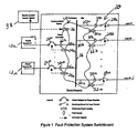
- a control system 10 includes a plurality of power sources 12a, 12b ... 12n supplying power through power source lines 14a, 14b ... 14n to a bus 16 and a plurality of loads 18a, 18b ... 18n receiving power from the bus 16 through corresponding load power circuits 20a, 20b ... 20n.
- Each of the power source lines 14a, 14b ... 14n has a fault sensor 22a, 22b ... 22n of a conventional type arranged to transmit a signal to a corresponding fault controller 24a, 24b ... 24n in response to sensing of a fault such as a short circuit in the corresponding power line.
- each of the circuit breakers 26a, 26b ... 26n is a fast acting, current limiting solid state circuit breaker to improve power continuity over the use of conventional circuit breakers.
- Each of the load circuits 20a, 20b ... 20n includes a simple switching device 28a, 28b ... 28n without any energy dissipation or storage device of the type required when interrupting a current carrying circuit. This permits the load circuit switching devices 28a, 28b ... 28n to be small, fast actuating and inexpensive. These switching devices are opened in response to a signal transmitted from a corresponding fault controller 32a, 32b... 32n.
- a communication circuit 34 is connected to each of the fault controllers 24a, 24b ... 24n and 32a, 32b ... 32n to transmit command signals for the operation of circuit breakers and switching devices in response to commands from the various fault controllers.
- any load line fault controller 32a, 32b ... 32n receives a fault detection signal from a fault sensor 30a, 30b... 30n in a load circuit 20a, 20b ...20n
- the fault controller transmits signals through the communication circuit 34 to the controllers 24a, 24b...24n for the power lines 14a, 14b...14n which supply power to the bus 16 to which the load circuit having the fault is connected.
- Those signals cause fault controllers 24a, 24b ...24n to open the corresponding circuit breakers 26a, 26b ... 26n and thereby terminate the supply of power to the group of load circuits containing the load circuit with the fault.
- the fault controller for the load line having the fault opens the corresponding switch under a no load condition, thereby avoiding the necessity for energy dissipation or storage arrangements.
- the corresponding controller 32a, 32b ... 32n transmits a signal through the circuit 34 to the controllers 24a, 24b ... 24n for the power source lines 14a, 14b ... 14n, causing them to close the corresponding circuit breakers 26a, 26b ...26n supplying power to the bus 16 and to the unaffected load lines 20a, 20b ... 20n.
- Fig. 2 shows the timing of the operation of the various circuit breakers and switches in the embodiment of the type shown in Fig. 1.
- This example assumes that two power sources, designated source 1 and source 2, are supplying power to the bus 16 and that three loads, designated load 1, load 2 and load 3, are receiving power from the bus 16 and that the load line leading to load 2 develops a fault.
- the power source line and load line fault controllers detect normal signals from the fault sensors during the time period designated T 1 and at the time T 2 the load controller for the load 2 detects a fault and transmits a signal during a message transmission period T 3 to the power source controllers to open the corresponding circuit breakers.
- the power source controllers receive the message to open the circuit breakers and command the circuit breakers to open, which takes place during a time interval T 5 .
- the power source controllers send a confirmation message to the load controller for the load 2 that the circuit breakers for the power supply circuits have been opened. These messages are transmitted during the time period T 7 and received at the time T 8 at which time the controller for load 2 commands the toad 2 switch to open. Opening of the load 2 switch occurs during the time interval T 9 , after which the load 2 controller sends a reclose message to the power source circuit breakers to reclose at a time T 10 .
- the power source controllers receive the reclose message and command the circuit breakers to reclose at a time T 12 . Closing of the circuit breakers 26 occurs during the time period T 13 and power is restored to the remaining loads 1 and 3 at the time T 14 .
- each of the steps described above occurs in a fraction of a millisecond.
- the length of the circuit breaker commutation period depends on the type of circuit breaker and the circuit characteristics and this step, which may require several milliseconds, will dominate the sequence of events.
- the power interruption, fault isolation and power recovery take place in essentially the time that it takes to interrupt power in the power supply lines, the time required for the other steps in the operation being negligible.
- Using fast acting circuit breakers for the power supply lines permits minimum power interruption as a result of a fault thereby providing improved power continuity in comparison with conventional arrangements which use a hierarchical method involving mechanical circuit breakers and fuses which are typically coordinated with intentional delays to allow downstream devices to open before upstream devices.
- a group controller 36 connected to a manual electric system control station 38 may be included in the communication circuit 34 to permit operator control of the system and to check the status of the fault controllers.
- a power source fault controller 24a, 24b ... 24n in one of the power lines 14a, 14b ...14n detects a fault which may, for example, be in the power line itself or in the distribution bus 16, that controller commands its corresponding circuit breaker 26a, 26b ... 26n to open and interrupt the power supply through the corresponding line.
- Any other fault controller 24a, 24b ... 24n in the lines 14a, 14b ...14n detecting its corresponding power source supplying the fault will also act to open the corresponding circuit breaker 26a, 26b ... 26n in the same manner. In the arrangement shown in Fig. 1, however, all of the loads which receive power from the bus 16 must remain powerless until the fault in the power source line or the distribution bus has been corrected.
- a multiple bus arrangement 40 of the type shown in Fig. 3 may be provided.
- a source power line 12a supplies power to the bus 16 which in turn transmits power to a plurality of loads 18a, 18b in the same manner described above.
- a second bus 42 receives power from the distribution bus 16 through a bus cross tie 60.
- An alternate power source is connected to bus 42 through a line 44 having a fault sensor 46, a fault controller 48 and a circuit breaker 50 of the same type included in the line 12a. If the distribution bus 42 is powered from distribution bus 16 through bus cross tie 60, then circuit breaker 50 can be in the open state.
- a vital load for which continuous supply of power is essential, is not connected directly to the bus 16 but receives power from the second bus 42 through a load power line 52.
- the line 52 has a fault sensor 54, a fault controller 56 responsive to the fault sensor, and a switch 58 which are essentially the same as the fault sensors and controllers and switches in the load lines 18a and 18b.
- the second bus 42 is connected to the bus 16 through a cross tie line 60 having a fault sensor 62, a fault controller 64 and a switch 66 which are also similar to the fault control arrangements of the load lines 18a and 18b.
- the power source line 12a supplies power to the buses 16 and 42 which are connected together through the cross tie 60.
- the circuit breaker for the power source line 12a is opened by the corresponding fault controller 24a in the manner described above and, upon receipt of confirmation signals through the communication circuit 34 that all of the circuit breakers are open, the controller 64 causes the switch 66 in the bus cross tie line 60 to open.
- the controller 48 receives a confirmation signal through the communication circuit 34 from fault controller 64 that the switch 66 has been opened, it causes the circuit breaker 50 to close thereby restoring power to the bus 42 and to the vital load.
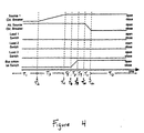
- Fig. 4 illustrates the time sequence of the events involved in the operation of the arrangement shown in Fig. 3.
- the controller 24a for the power source line 12a detects a fault and commands the circuit breaker 26a to open, which occurs during the time period T 3 .
- the controllers 24a and 48 send open confirmation signals to the controller 64 which occurs during time period T 5 .
- controller 64 commands the cross tie switch 66 to open. Opening of the cross tie switch takes place during the time T 7 and when the cross tie switch is open at T 8 , the controller 64 sends an open confirmation signal to the alternate power source controller 48 during a message transmission period T 9 .
- the alternate source controller 48 commands its circuit breaker 50 to close, which occurs during the time period T 11 , so that at the time T 12 , power has been restored to the vital load.
- the fault controllers perform an automatic realignment of the system to supply the loads on the lines 18a, 18b and 52 from the alternate power source.
- the corresponding controller 24a commands the circuit breaker 26a to open and sends a close message to the alternate power source controller 48.
- the alternate power source controller then closes its circuit breaker to restore power to the loads.
- the arrangement of the fault controller communication circuit 34 in Figs. 1 and 3 as a ring circuit may, if desired, be replaced by a point to point, star, or any other circuit configuration which permits each controller to detect signals from all of the controllers and to supply signals to all of the controllers. If desired, the fault controllers may also be arranged to keep a historical log of fault locations and electrical system protective device status for maintenance and trouble shooting purposes.
- the group controller 36 and electrical system control station 38 shown in Figs. 1 and 3 permit operator control of the electric power distribution system so that an operator at the central control station may receive fault indications from the various controllers and transmit appropriate fault controller commands.
- the group controller may also be used to check the status of the protective system and to provide the other fault controllers with new fault detection criteria or to disable automated system realignments.
- the communication circuit 34 may be a physical connection, such as wire or fiber optic cable, or it may be a wireless connection.
- Each of the fault controllers requires a reliable power source for operation since the fault controllers must operate when the power sources have been disconnected.
- the arrangement of the invention may be utilized with a single master fault controller rather than dedicated fault controllers for each protective device.
- the master fault controller is arranged to communicate with every fault sensor and every protective device. This significantly reduces the total amount of hardware needed to implement the protective system.
- a secondary or back-up master fault controller could also be provided for resiliency.
- the communication circuit 34 connecting the various fault controllers shown in Figs. 1 and 3 can be eliminated while retaining ability to automatically isolate faults but, without the communications system 34, automated system realignments cannot be effected.
- a load controller detecting a fault sets an internal flag to provide an open command to its switching device when its corresponding fault sensor indicates the circuit has been interrupted (i.e., denotes zero current).
- a power source fault controller detecting the fault commands its circuit breaker to open, then waits a short period of time and commands its circuit breaker to re-close. During that time interval the load fault controller detects the circuit interruption and commands its switching device to open.
- the circuit breaker If the fault is upstream of a load, the circuit breaker recloses and the power source continues to supply the fault but the power source fault controller then again detects the fault and commands the circuit breaker to reopen. The power source fault controller then waits, realizing the fault has not been isolated, or continues to reclose and open for a predetermined number of attempts.
- This arrangement provides a simplified protective system while still assuring automatic fault isolation without the detriments of a conventional system taking into account the transient requirements of the system. In addition to eliminating the fault controller communication system, this arrangement does not require fault controllers to have knowledge of present and future system alignments.
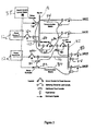
- the fault controller arrangement may be implemented on a distribution bus level rather than the described source level implementation.
- the arrangement includes Bus #1 and Bus #2 connected by a bus cross tie line as well as circuit breakers 72a and 74a and controllers 72 and 74 associated with power source #1 and power source #2 respectively, and a controller 78 and a switch 80 associated with load #3.
- the bus cross tie line includes a circuit breaker 68a and a controller 68 associated with Bus #1 and a circuit breaker 70a and a controller 70 associated with Bus #2.
- a group controller 82 controls a separate communication circuit 84 for the controllers associated with Bus #2.
- Such an arrangement requires more fault energy dissipation or absorption capacity since, instead of providing one circuit breaker for each power source, circuit breakers are required for every potential incoming power path to a distribution bus or group of distribution buses. Although more circuit breakers are necessary with this arrangement, the fault controllers associated with the distribution bus or group of buses do not have to communicate with fault controllers protecting another portion of the system. This provides an advantage with electric power distribution systems which are spread out over a large area or are otherwise difficult to link through a communication system.
- Fig. 6 illustrates the time sequence of the events involved in the operation of the arrangement shown in Fig. 5.
- the fault controllers detect normal signals from the fault sensors during the time period T 1 and at the time T 2
- the load controller 78 for load #3 detects a fault and transmits a signal during a message transmission period T 3 to the power source #2 controller 74 and Bus #2 cross tie line controller 70 to open the corresponding circuit breaker 74a and bus cross tie circuit breaker 70a.
- the controllers 74 and 70 receive the message to open the circuit breakers 74a and 70a and command the circuit breakers to open, which takes place during the time interval T 5 .
- the controllers 74 and 70 send an open confirmation message to the load controller 78 for load #3 that the circuit breakers for the power supply #2 and for the bus #2 cross tie line have been opened. These messages are transmitted during the time period T 7 and received at the time T 8 at which time the controller 78 for load #3 commands the load #3 switch 80 to open. Opening of the load #3 switch 80 occurs during the time interval T 9 , after which the load #3 controller 78 sends a reclose message to power source controllers 74 and 70 to reclose the circuit breakers 74a and 70a at time T 10 . Following a message transmission period T 11 , controllers 74 and 70 receive the reclose message at time T 12 . Closing of the circuit breakers 74a and 70a occurs during the time period T 13 and power is restored to load #4 at the time T 14 . During the process, there has been no power interruption to loads #1 and #2.
Description
- This invention relates to a fault protection arrangement and methods for fault protection in electric power distribution systems.
- The protection of personnel and electric system components, such as generators, motors, cables and power conversion equipment from short circuit conditions and other system anomalies is essential for safe and reliable distribution of electric power. Power continuity may also be critical for vital loads within a system. Heretofore, hierarchical protective arrangements using mechanical circuit breakers and fuses have been designed to utilize downstream protective devices which open first in order to clear a fault in a downstream circuit segment. In such systems the response times are slow and many protective devices are required. Moreover, time coordination of protective devices is necessary and, where fuses are used, blown fuses must be replaced before the system is completely restored.
- JP 05091670 discloses buses that are interlinked through a semiconductor device for distributing power from a plurality of transformers. Distribution lines are provided from the buses that have respective fault detection sections. When the current exceeds a predetermined level with the semiconductor device on, a supervisory control section turns off the semiconductor device before a circuit breaker for each distribution line is turned off.
- According to one aspect of the present invention there is provided a fault protection arrangement for an electric power distribution system comprising:
- at least one power distribution bus;
- at least one power source line connected to the power distribution bus;
- a circuit interruption means in the power source line;
- a load line connected to the power distribution bus to supply power to a load;
- a fault sensor in said load line;
- a switch in said load line; and
- control means responsive to detection of a fault in said load line by said fault sensor to cause the circuit interruption means in the power source line to open, then cause the switch in the faulted load line to open and then cause the circuit interruption means in the power source line to close.
-
- Other features of the present invention are apparent from
Claims 2 to 22. - It will be appreciated that the present invention provides automatic fault isolation and automatic system realignment more rapidly and with fewer components than prior art systems.
- According to another aspect of the present invention there is provided a method for fault protection in an electric power distribution system using an arrangement in accordance with the present invention, which method comprises the steps of:
- detecting a fault in the or a load line connected to the power distribution bus;
- causing the circuit interruption means in the or each of the power source lines to open;
- causing the switch in the load line to open; and
- re-closing the circuit interruption means in the or each of the power source lines connected to the power distribution bus.
-
- Preferably, when using one particular arrangement according to the present invention, the method further comprises the step of causing the dedicated circuit interruption means in the cross tie lime to open in addition to the step of causing the circuit interruption means in the or each of the power source lines to open.
- Advantageously, if said fault is re-detected after re-closing the circuit interruption means in the or each power source line, said method further comprises the steps of:
- (a) causing the circuit interruption means to reopen;
- (b) waiting for a pre-determined time period before re-closing the circuit interruption means in the or each power source line; and repeating steps (a) and (b) upon re-detection of said fault.
-
- According to a further aspect of the present invention there is provided a method for fault protection in an electric power distribution system using an arrangement in accordance with the invention, which method comprises the steps of:
- detecting a fault in the power distribution bus or an associated power source line;
- causing the circuit interruption means in the power source line(s) connected to the power distribution bus to open; and
- closing the circuit interruption means in the alternate power source line connected to the second power distribution bus.
-
- Other features of this aspect of the present invention are apparent from
Claims 27 and 28. - For a better understanding of the present invention reference will now be made, by way of example, to the accompanying drawings, in which:-
- Fig. 1 shows schematically a circuit diagram illustrating a first embodiment of a fault protection arrangement in accordance with the present invention in use with an electric power distribution system;
- Fig. 2 shows schematically a timing diagram illustrating the relation of the operating times for the various components of the fault protection arrangement shown in Fig. 1;
- Fig. 3 shows schematically a circuit diagram illustrating a second embodiment of a fault protection arrangement in accordance with the present invention in use with an electric power distribution system;
- Fig. 4 shows schematically a timing diagram illustrating the relation of the operating times of the various components of the fault protection arrangement shown in Fig. 3;
- Fig. 5 shows schematically a circuit diagram illustrating a third embodiment of a fault protection arrangement in accordance with the present invention in use with an electric power distribution system; and
- Fig. 6 shows schematically a timing diagram illustrating the relation of the operating times of the various components of the fault protection arrangement shown in Fig. 5.
-
- In the first embodiment of the invention shown in Fig. 1, a control system 10 includes a plurality of power sources 12a, 12b ... 12n supplying power through power source lines 14a, 14b ... 14n to a
bus 16 and a plurality of loads 18a, 18b ... 18n receiving power from thebus 16 through correspondingload power circuits 20a, 20b ... 20n. Each of the power source lines 14a, 14b ... 14n has afault sensor 22a, 22b ... 22n of a conventional type arranged to transmit a signal to a corresponding fault controller 24a, 24b ... 24n in response to sensing of a fault such as a short circuit in the corresponding power line.Circuit breakers 26a, 26b ... 26n are included in each of the power source lines 14a, 14b ... 14n and respond to signals from the corresponding fault controllers 24a, 24b ... 24n to open the circuit between the corresponding power source and thebus 16. Preferably each of thecircuit breakers 26a, 26b ... 26n is a fast acting, current limiting solid state circuit breaker to improve power continuity over the use of conventional circuit breakers. - Each of the
load circuits 20a, 20b ... 20n, on other hand, includes a simple switching device 28a, 28b ... 28n without any energy dissipation or storage device of the type required when interrupting a current carrying circuit. This permits the load circuit switching devices 28a, 28b ... 28n to be small, fast actuating and inexpensive. These switching devices are opened in response to a signal transmitted from a corresponding fault controller 32a, 32b... 32n. - In order to control the opening and closing of the
circuit breakers 26a, 26b ... 26n and the switches 28a, 28b ... 28n, acommunication circuit 34 is connected to each of the fault controllers 24a, 24b ... 24n and 32a, 32b ... 32n to transmit command signals for the operation of circuit breakers and switching devices in response to commands from the various fault controllers. - In accordance with the invention, whenever any load line fault controller 32a, 32b ... 32n receives a fault detection signal from a
fault sensor 30a, 30b... 30n in aload circuit 20a, 20b ...20n, the fault controller transmits signals through thecommunication circuit 34 to the controllers 24a, 24b...24n for the power lines 14a, 14b...14n which supply power to thebus 16 to which the load circuit having the fault is connected. Those signals cause fault controllers 24a, 24b ...24n to open thecorresponding circuit breakers 26a, 26b ... 26n and thereby terminate the supply of power to the group of load circuits containing the load circuit with the fault. Upon receipt of signals through thecommunication circuit 34 that all of the power source lines have been opened, the fault controller for the load line having the fault opens the corresponding switch under a no load condition, thereby avoiding the necessity for energy dissipation or storage arrangements. As soon as the switch 28a, 28b ... 28n has been opened, the corresponding controller 32a, 32b ... 32n transmits a signal through thecircuit 34 to the controllers 24a, 24b ... 24n for the power source lines 14a, 14b ... 14n, causing them to close thecorresponding circuit breakers 26a, 26b ...26n supplying power to thebus 16 and to theunaffected load lines 20a, 20b ... 20n. - Fig. 2 shows the timing of the operation of the various circuit breakers and switches in the embodiment of the type shown in Fig. 1. This example assumes that two power sources, designated
source 1 andsource 2, are supplying power to thebus 16 and that three loads, designatedload 1,load 2 andload 3, are receiving power from thebus 16 and that the load line leading toload 2 develops a fault. In the illustrated operation sequence, the power source line and load line fault controllers detect normal signals from the fault sensors during the time period designated T1 and at the time T2 the load controller for theload 2 detects a fault and transmits a signal during a message transmission period T3 to the power source controllers to open the corresponding circuit breakers. At the time T4, the power source controllers receive the message to open the circuit breakers and command the circuit breakers to open, which takes place during a time interval T5. At the time T6 the power source controllers send a confirmation message to the load controller for theload 2 that the circuit breakers for the power supply circuits have been opened. These messages are transmitted during the time period T7 and received at the time T8 at which time the controller forload 2 commands thetoad 2 switch to open. Opening of theload 2 switch occurs during the time interval T9, after which theload 2 controller sends a reclose message to the power source circuit breakers to reclose at a time T10. Following a transmission time period T11, the power source controllers receive the reclose message and command the circuit breakers to reclose at a time T12. Closing of the circuit breakers 26 occurs during the time period T13 and power is restored to theremaining loads - Except for the circuit breaker commutation period T5, each of the steps described above occurs in a fraction of a millisecond. The length of the circuit breaker commutation period depends on the type of circuit breaker and the circuit characteristics and this step, which may require several milliseconds, will dominate the sequence of events. Thus, the power interruption, fault isolation and power recovery take place in essentially the time that it takes to interrupt power in the power supply lines, the time required for the other steps in the operation being negligible. Using fast acting circuit breakers for the power supply lines permits minimum power interruption as a result of a fault thereby providing improved power continuity in comparison with conventional arrangements which use a hierarchical method involving mechanical circuit breakers and fuses which are typically coordinated with intentional delays to allow downstream devices to open before upstream devices. Eliminating these delays and avoiding the use of magnetically and thermally activated devices significantly improves power continuity while reducing energy passing through during a fault. If desired, a
group controller 36 connected to a manual electricsystem control station 38 may be included in thecommunication circuit 34 to permit operator control of the system and to check the status of the fault controllers. - If a power source fault controller 24a, 24b ... 24n in one of the power lines 14a, 14b ...14n detects a fault which may, for example, be in the power line itself or in the
distribution bus 16, that controller commands itscorresponding circuit breaker 26a, 26b ... 26n to open and interrupt the power supply through the corresponding line. Any other fault controller 24a, 24b ... 24n in the lines 14a, 14b ...14n detecting its corresponding power source supplying the fault will also act to open thecorresponding circuit breaker 26a, 26b ... 26n in the same manner. In the arrangement shown in Fig. 1, however, all of the loads which receive power from thebus 16 must remain powerless until the fault in the power source line or the distribution bus has been corrected. - In order to eliminate that problem, a
multiple bus arrangement 40 of the type shown in Fig. 3 may be provided. In this arrangement a source power line 12a supplies power to thebus 16 which in turn transmits power to a plurality of loads 18a, 18b in the same manner described above. In addition, however, a second bus 42 receives power from thedistribution bus 16 through a bus cross tie 60. An alternate power source is connected to bus 42 through aline 44 having a fault sensor 46, afault controller 48 and acircuit breaker 50 of the same type included in the line 12a. If the distribution bus 42 is powered fromdistribution bus 16 through bus cross tie 60, thencircuit breaker 50 can be in the open state. A vital load, for which continuous supply of power is essential, is not connected directly to thebus 16 but receives power from the second bus 42 through a load power line 52. The line 52 has a fault sensor 54, afault controller 56 responsive to the fault sensor, and aswitch 58 which are essentially the same as the fault sensors and controllers and switches in the load lines 18a and 18b. The second bus 42 is connected to thebus 16 through a cross tie line 60 having a fault sensor 62, afault controller 64 and a switch 66 which are also similar to the fault control arrangements of the load lines 18a and 18b. - In normal operation, the power source line 12a supplies power to the
buses 16 and 42 which are connected together through the cross tie 60. In the event of a fault in thebus 16 or the power source line 12a, the circuit breaker for the power source line 12a is opened by the corresponding fault controller 24a in the manner described above and, upon receipt of confirmation signals through thecommunication circuit 34 that all of the circuit breakers are open, thecontroller 64 causes the switch 66 in the bus cross tie line 60 to open. When thecontroller 48 receives a confirmation signal through thecommunication circuit 34 fromfault controller 64 that the switch 66 has been opened, it causes thecircuit breaker 50 to close thereby restoring power to the bus 42 and to the vital load. - Fig. 4 illustrates the time sequence of the events involved in the operation of the arrangement shown in Fig. 3. During the time period T1 all of the fault controllers detect normal signals from the fault sensors. At the time T2, the controller 24a for the power source line 12a detects a fault and commands the
circuit breaker 26a to open, which occurs during the time period T3. At the time T4, thecontrollers 24a and 48 send open confirmation signals to thecontroller 64 which occurs during time period T5. At time period T6,controller 64 commands the cross tie switch 66 to open. Opening of the cross tie switch takes place during the time T7 and when the cross tie switch is open at T8, thecontroller 64 sends an open confirmation signal to the alternatepower source controller 48 during a message transmission period T9. At the time T10, thealternate source controller 48 commands itscircuit breaker 50 to close, which occurs during the time period T11, so that at the time T12, power has been restored to the vital load. - In the arrangement shown in Fig. 3, if the primary power source supplying power through the line 12a fails or is taken out of service for some reason, the fault controllers perform an automatic realignment of the system to supply the loads on the lines 18a, 18b and 52 from the alternate power source. For this purpose, when the
sensor 22a in the line 12a detects a loss of power, the corresponding controller 24a commands thecircuit breaker 26a to open and sends a close message to the alternatepower source controller 48. The alternate power source controller then closes its circuit breaker to restore power to the loads. - The arrangement of the fault
controller communication circuit 34 in Figs. 1 and 3 as a ring circuit may, if desired, be replaced by a point to point, star, or any other circuit configuration which permits each controller to detect signals from all of the controllers and to supply signals to all of the controllers. If desired, the fault controllers may also be arranged to keep a historical log of fault locations and electrical system protective device status for maintenance and trouble shooting purposes. Thegroup controller 36 and electricalsystem control station 38 shown in Figs. 1 and 3 permit operator control of the electric power distribution system so that an operator at the central control station may receive fault indications from the various controllers and transmit appropriate fault controller commands. The group controller may also be used to check the status of the protective system and to provide the other fault controllers with new fault detection criteria or to disable automated system realignments. Moreover, thecommunication circuit 34 may be a physical connection, such as wire or fiber optic cable, or it may be a wireless connection. Each of the fault controllers requires a reliable power source for operation since the fault controllers must operate when the power sources have been disconnected. - Furthermore, the arrangement of the invention may be utilized with a single master fault controller rather than dedicated fault controllers for each protective device. In this case, the master fault controller is arranged to communicate with every fault sensor and every protective device. This significantly reduces the total amount of hardware needed to implement the protective system. A secondary or back-up master fault controller could also be provided for resiliency.
- If desired, the
communication circuit 34 connecting the various fault controllers shown in Figs. 1 and 3 can be eliminated while retaining ability to automatically isolate faults but, without thecommunications system 34, automated system realignments cannot be effected. In the absence of a communication system, a load controller detecting a fault sets an internal flag to provide an open command to its switching device when its corresponding fault sensor indicates the circuit has been interrupted (i.e., denotes zero current). A power source fault controller detecting the fault commands its circuit breaker to open, then waits a short period of time and commands its circuit breaker to re-close. During that time interval the load fault controller detects the circuit interruption and commands its switching device to open. If the fault is upstream of a load, the circuit breaker recloses and the power source continues to supply the fault but the power source fault controller then again detects the fault and commands the circuit breaker to reopen. The power source fault controller then waits, realizing the fault has not been isolated, or continues to reclose and open for a predetermined number of attempts. This arrangement provides a simplified protective system while still assuring automatic fault isolation without the detriments of a conventional system taking into account the transient requirements of the system. In addition to eliminating the fault controller communication system, this arrangement does not require fault controllers to have knowledge of present and future system alignments. - In the third embodiment shown in Fig. 5, the fault controller arrangement may be implemented on a distribution bus level rather than the described source level implementation. The arrangement includes
Bus # 1 andBus # 2 connected by a bus cross tie line as well ascircuit breakers 72a and 74a andcontrollers power source # 1 andpower source # 2 respectively, and acontroller 78 and aswitch 80 associated withload # 3. The bus cross tie line includes a circuit breaker 68a and acontroller 68 associated withBus # 1 and a circuit breaker 70a and a controller 70 associated withBus # 2. In addition, agroup controller 82 controls aseparate communication circuit 84 for the controllers associated withBus # 2. Such an arrangement requires more fault energy dissipation or absorption capacity since, instead of providing one circuit breaker for each power source, circuit breakers are required for every potential incoming power path to a distribution bus or group of distribution buses. Although more circuit breakers are necessary with this arrangement, the fault controllers associated with the distribution bus or group of buses do not have to communicate with fault controllers protecting another portion of the system. This provides an advantage with electric power distribution systems which are spread out over a large area or are otherwise difficult to link through a communication system. - Fig. 6 illustrates the time sequence of the events involved in the operation of the arrangement shown in Fig. 5. The fault controllers detect normal signals from the fault sensors during the time period T1 and at the time T2, the
load controller 78 forload # 3 detects a fault and transmits a signal during a message transmission period T3 to thepower source # 2controller 74 andBus # 2 cross tie line controller 70 to open thecorresponding circuit breaker 74a and bus cross tie circuit breaker 70a. At the time T4, thecontrollers 74 and 70 receive the message to open thecircuit breakers 74a and 70a and command the circuit breakers to open, which takes place during the time interval T5. At the time T6, thecontrollers 74 and 70 send an open confirmation message to theload controller 78 forload # 3 that the circuit breakers for thepower supply # 2 and for thebus # 2 cross tie line have been opened. These messages are transmitted during the time period T7 and received at the time T8 at which time thecontroller 78 forload # 3 commands theload # 3switch 80 to open. Opening of theload # 3switch 80 occurs during the time interval T9, after which theload # 3controller 78 sends a reclose message topower source controllers 74 and 70 to reclose thecircuit breakers 74a and 70a at time T10. Following a message transmission period T11,controllers 74 and 70 receive the reclose message at time T12. Closing of thecircuit breakers 74a and 70a occurs during the time period T13 and power is restored to load #4 at the time T14. During the process, there has been no power interruption toloads # 1 and #2.
Claims (28)
- A fault protection arrangement for an electric power distribution system comprising:at least one power distribution bus (16);at least one power source line (14a, 14b ... 14n) connected to the power distribution bus (16) ;a circuit interruption means (26a, 26b ... 26n; 72a, 74a) in the power source line (14a, 14b ... 14n) ;a load line (20a, 20b ... 20n) connected to the power distribution bus to supply power to a load (18a, 18b ... 18n) ;a fault sensor (30a, 30b ... 30n) in said load line;a switch (28a, 28b ... 28n) in said load line; andcontrol means (24a, 24b ... 24n, 32a, 32b ... 32n) responsive to detection of a fault in said load line (20a, 20b ... 20n) by said fault sensor (30a, 30b ... 30n) to cause the circuit interruption means (26a, 26b ... 26n) in the power source line (14a, 14b ... 14n) to open, then cause the switch (28a, 28b ... 28n) in the faulted load line to open and then cause the circuit interruption means (26a, 26b ... 26n; 72a, 74a) in the power source line (14a, 14b ... 14n) to close.
- A fault protection arrangement as claimed in Claim 1, wherein said at least one power source line (14a, 14b ... 14n) is provided with a fault sensor (22a, 22b ... 22n).
- A fault protection arrangement as claimed in Claim 1 or 2, including means to inhibit said switch being opened whilst carrying current.
- A fault protection arrangement as claimed in Claim 1, 2 or 3, further comprising a plurality of load lines each with a respective fault sensor and a respective switch.
- A fault protection arrangement as claimed in Claim 1, 2, 3 or 4, further comprising a plurality of power source lines each with a respective circuit interruption means.
- A fault protection arrangement as claimed in Claim 5, wherein each power source line is provided with a respective fault sensor.
- A fault protection arrangement as claimed in any preceding Claim, further comprising a fault controller associated with the or each of said circuit interruption means and a fault controller associated with the or each of said switches.
- A fault protection arrangement as claimed in Claim 7, including communication means (34) to enable said fault controllers to communicate with one another such that in use, said fault controllers can send and receive signals to and from one another.
- A fault protection arrangement as claimed in any of Claims 1 to 6, further comprising a master fault controller (36) associated with the or each circuit interruption means and the or each of said switches.
- A fault protection arrangement as claimed in Claim 7, wherein there is a plurality of power distribution buses, the arrangement further comprising
a respective cross tie line (60) connecting each power distribution bus with one other power distribution bus;
a plurality of circuit interruption means (68a, 70a) in each respective cross tie line, each of the plurality of circuit interruption means (68a, 70a) dedicated to one of the plurality of power distribution buses connected by the respective cross tie line;
a plurality of fault sensors in each respective cross tie line; and
a plurality of fault controller arrangements (72, 74), each responsive to detection of a fault in one of the plurality of power distribution buses, at least one respective power source line and at least one respective load line, to cause the dedicated circuit interruption means in the cross tie line (60) to open. - A fault protection arrangement as claimed in Claim 2, or any Claim dependent directly or indirectly thereon, further comprising:wherein said control means are responsive to detection of a fault by said fault sensor in the or a power source line to cause the circuit interruption means (72a, 74a) in the power source line(s) to open, and then the circuit interruption means (74a) in the alternate power source line (44) to close.a second power distribution bus (42);a cross tie line (60) connecting the power distribution bus (16) with the second power distribution bus (42);an alternate power source line (44) connected to the second power distribution bus (42);a circuit interruption means (50) in the alternate power source line;
- A fault protection arrangement as claimed in Claim 11, further comprising a switch (66) in said cross tie line, the arrangement being such that in use said control means are responsive to detection of a fault in said power distribution bus by said fault sensor in said at least one power source line to cause the circuit interruption means to open, then the switch in said cross tie line to open and then the circuit interruption means in the alternate power source line to close.
- A fault protection arrangement as claimed in Claim 11 or 12, further comprising a fault sensor (62) in said cross tie line.
- A fault protection arrangement as claimed in Claim 13, including means to inhibit said switch in said cross tie line being opened whilst carrying current.
- A fault protection arrangement as claimed in Claim 11, 12, 13 or 14, further comprising a fault sensor (46) in said alternate power supply line.
- A fault protection arrangement as claimed in any of Claims 11 to 15, including a further load line (52) connected to said second power distribution bus to supply power to a further load.
- A fault protection arrangement as claimed in Claim 16, wherein said further load line comprises a fault sensor (54) and a switch (58).
- A fault protection arrangement as claimed in Claim 17, further comprising a plurality of further load lines each with a respective fault sensor and a respective switch.
- A fault protection arrangement as claimed in any preceding Claim, further comprising a group controller (36) and a manual control station (38), the arrangement being such that in use a human operator can operate said manual control station to selectively monitor and operate said circuit interruption means and said switch(es).
- A fault protection arrangement as claimed in Claim 8, or any claim dependent directly or indirectly thereon, wherein said communication means comprises one or more of a ring circuit, a point to point circuit, a star circuit, a wireless connection and a fibre optic cable.
- A fault protection arrangement as claimed in any preceding Claim, wherein said circuit interruption means comprises one of a solid state electronic device and an electro-mechanical device.
- A fault protection arrangement as claimed in any preceding Claim, wherein said switch comprises one of a solid state electronic device and an electro-mechanical device.
- A method for fault protection in an electric power distribution system using an arrangement as claimed in any of Claims 1 to 22, which method comprises the steps of:detecting a fault in the or a load line (20a, 20b ... 20n) connected to the power distribution bus (16) ;causing the circuit interruption means (26a, 26b ... 26n) in the or each of the power source lines to open;causing the switch (28a, 28b ... 28n) in the load line to open; andre-closing the circuit interruption means in the or each of the power source lines connected to the power distribution bus.
- A method as claimed in Claim 23, when using an arrangement as claimed in Claim 10, further comprising the step of causing the dedicated circuit interruption means (68a, 70a) in the cross tie line to open in addition to the step of causing the circuit interruption means in the or each of the power source lines to open.
- A method as claimed in Claim 23 or 24, wherein if said fault is re-detected after re-closing the circuit interruption means in the or each power source line, said method further comprises the steps of:repeating steps (a) and (b) upon re-detection of said fault.(a) causing the circuit interruption means to reopen;(b) waiting for a pre-determined time period before re-closing the circuit interruption means in the or each power source line; and
- A method for fault protection in an electric power distribution system using an arrangement as claimed in any of Claims 11 to 20, which method comprises the steps of:detecting a fault in the power distribution bus (16, 42) or an associated power source line (12a, 44);causing the circuit interruption means (26a, 50, ... 72a, 74a) in the power source line(s) connected to the power distribution bus (16; 42) to open; andclosing the circuit interruption means (50) in the alternate power source line (44) connected to the second power distribution bus (42).
- A method as claimed in Claim 26, further comprising the step of opening the circuit interruption means in the alternate power source line.
- A method as claimed in Claim 26 or 27 when dependent directly or indirectly on Claim 11, further comprising the step of opening the switch (66) in the cross tie line (60).
Applications Claiming Priority (2)
| Application Number | Priority Date | Filing Date | Title |
|---|---|---|---|
| US46078 | 1979-06-06 | ||
| US09/046,078 US6008971A (en) | 1998-03-23 | 1998-03-23 | Fault protection arrangement for electric power distribution systems |
Publications (3)
| Publication Number | Publication Date |
|---|---|
| EP0948111A2 EP0948111A2 (en) | 1999-10-06 |
| EP0948111A3 EP0948111A3 (en) | 2001-05-09 |
| EP0948111B1 true EP0948111B1 (en) | 2002-11-27 |
Family
ID=21941484
Family Applications (1)
| Application Number | Title | Priority Date | Filing Date |
|---|---|---|---|
| EP99200880A Expired - Fee Related EP0948111B1 (en) | 1998-03-23 | 1999-03-22 | Fault protection arrangements and methods for electric power distribution systems |
Country Status (4)
| Country | Link |
|---|---|
| US (1) | US6008971A (en) |
| EP (1) | EP0948111B1 (en) |
| JP (1) | JPH11313438A (en) |
| DE (1) | DE69904096T2 (en) |
Families Citing this family (101)
| Publication number | Priority date | Publication date | Assignee | Title |
|---|---|---|---|---|
| US6347027B1 (en) | 1997-11-26 | 2002-02-12 | Energyline Systems, Inc. | Method and apparatus for automated reconfiguration of an electric power distribution system with enhanced protection |
| JP2000139025A (en) * | 1998-10-30 | 2000-05-16 | Mitsubishi Electric Corp | Device and method for controlling power distribution |
| JP2000209771A (en) * | 1999-01-08 | 2000-07-28 | Mitsubishi Electric Corp | Protective relay device for distribution facility |
| US6496342B1 (en) | 1999-02-12 | 2002-12-17 | Bitronics Inc. | Distributed monitoring and protection system for a distributed power network |
| US6411865B1 (en) * | 2000-06-26 | 2002-06-25 | Schweitzer Engineering Laboratories, Inc. | System for protection zone selection in microprocessor-based relays in an electric power system |
| US7265652B2 (en) | 2001-07-10 | 2007-09-04 | Yingco Electronic Inc. | Controllable electronic switch |
| US7324876B2 (en) * | 2001-07-10 | 2008-01-29 | Yingco Electronic Inc. | System for remotely controlling energy distribution at local sites |
| US7110231B1 (en) | 2002-08-30 | 2006-09-19 | Abb Inc. | Adaptive protection system for a power-distribution network |
| US6816757B1 (en) | 2002-09-19 | 2004-11-09 | Abb Technology Ag | Control unit for a power-distribution network |
| EP1554642A1 (en) * | 2002-10-15 | 2005-07-20 | Powerdsine Ltd. | Direct current power pooling |
| US7170194B2 (en) * | 2002-10-15 | 2007-01-30 | Powerdsine, Ltd. | Configurable multiple power source system |
| US6839210B2 (en) * | 2002-10-25 | 2005-01-04 | Schweitzer Engineering Laboratories, Inc. | Bus total overcurrent system for a protective relay |
| BRPI0314881B1 (en) * | 2002-10-25 | 2019-01-08 | S & C Electric Co | system and method for controlling distribution of electricity through a grid |
| PL1782517T3 (en) * | 2004-08-18 | 2013-11-29 | Siemens Ag | Device for the safe isolation of a nuclear power plant from a supply mains during a mains failure |
| US7414819B2 (en) * | 2004-12-03 | 2008-08-19 | Schweitzer Engineering Laboratories, Inc. | Methods and systems for sectionalizing a looped distribution line in a power distribution system |
| US20060149873A1 (en) * | 2005-01-04 | 2006-07-06 | Underwood Brad O | Bus isolation apparatus and method |
| US7446491B2 (en) * | 2005-02-24 | 2008-11-04 | Abb Ltd. | Intelligent power management for actuators |
| US7627774B2 (en) * | 2005-02-25 | 2009-12-01 | Hewlett-Packard Development Company, L.P. | Redundant manager modules to perform management tasks with respect to an interconnect structure and power supplies |
| US11881814B2 (en) | 2005-12-05 | 2024-01-23 | Solaredge Technologies Ltd. | Testing of a photovoltaic panel |
| US10693415B2 (en) | 2007-12-05 | 2020-06-23 | Solaredge Technologies Ltd. | Testing of a photovoltaic panel |
| US8036872B2 (en) * | 2006-03-10 | 2011-10-11 | Edsa Micro Corporation | Systems and methods for performing automatic real-time harmonics analyses for use in real-time power analytics of an electrical power distribution system |
| US20160246905A1 (en) | 2006-02-14 | 2016-08-25 | Power Analytics Corporation | Method For Predicting Arc Flash Energy And PPE Category Within A Real-Time Monitoring System |
| US9557723B2 (en) | 2006-07-19 | 2017-01-31 | Power Analytics Corporation | Real-time predictive systems for intelligent energy monitoring and management of electrical power networks |
| US8959006B2 (en) * | 2006-03-10 | 2015-02-17 | Power Analytics Corporation | Systems and methods for automatic real-time capacity assessment for use in real-time power analytics of an electrical power distribution system |
| US20170046458A1 (en) | 2006-02-14 | 2017-02-16 | Power Analytics Corporation | Systems and methods for real-time dc microgrid power analytics for mission-critical power systems |
| US9092593B2 (en) | 2007-09-25 | 2015-07-28 | Power Analytics Corporation | Systems and methods for intuitive modeling of complex networks in a digital environment |
| US8126685B2 (en) * | 2006-04-12 | 2012-02-28 | Edsa Micro Corporation | Automatic real-time optimization and intelligent control of electrical power distribution and transmission systems |
| US7460929B2 (en) * | 2006-05-01 | 2008-12-02 | Agere Systems Inc. | Integrated current fault controller |
| US8319471B2 (en) | 2006-12-06 | 2012-11-27 | Solaredge, Ltd. | Battery power delivery module |
| US9088178B2 (en) | 2006-12-06 | 2015-07-21 | Solaredge Technologies Ltd | Distributed power harvesting systems using DC power sources |
| WO2009073868A1 (en) | 2007-12-05 | 2009-06-11 | Solaredge, Ltd. | Safety mechanisms, wake up and shutdown methods in distributed power installations |
| US8963369B2 (en) | 2007-12-04 | 2015-02-24 | Solaredge Technologies Ltd. | Distributed power harvesting systems using DC power sources |
| US8947194B2 (en) | 2009-05-26 | 2015-02-03 | Solaredge Technologies Ltd. | Theft detection and prevention in a power generation system |
| US11309832B2 (en) | 2006-12-06 | 2022-04-19 | Solaredge Technologies Ltd. | Distributed power harvesting systems using DC power sources |
| US11296650B2 (en) | 2006-12-06 | 2022-04-05 | Solaredge Technologies Ltd. | System and method for protection during inverter shutdown in distributed power installations |
| US11855231B2 (en) | 2006-12-06 | 2023-12-26 | Solaredge Technologies Ltd. | Distributed power harvesting systems using DC power sources |
| US8013472B2 (en) | 2006-12-06 | 2011-09-06 | Solaredge, Ltd. | Method for distributed power harvesting using DC power sources |
| US11687112B2 (en) | 2006-12-06 | 2023-06-27 | Solaredge Technologies Ltd. | Distributed power harvesting systems using DC power sources |
| US8384243B2 (en) | 2007-12-04 | 2013-02-26 | Solaredge Technologies Ltd. | Distributed power harvesting systems using DC power sources |
| US8319483B2 (en) | 2007-08-06 | 2012-11-27 | Solaredge Technologies Ltd. | Digital average input current control in power converter |
| US11888387B2 (en) | 2006-12-06 | 2024-01-30 | Solaredge Technologies Ltd. | Safety mechanisms, wake up and shutdown methods in distributed power installations |
| US11735910B2 (en) | 2006-12-06 | 2023-08-22 | Solaredge Technologies Ltd. | Distributed power system using direct current power sources |
| US8816535B2 (en) | 2007-10-10 | 2014-08-26 | Solaredge Technologies, Ltd. | System and method for protection during inverter shutdown in distributed power installations |
| US8473250B2 (en) | 2006-12-06 | 2013-06-25 | Solaredge, Ltd. | Monitoring of distributed power harvesting systems using DC power sources |
| US11728768B2 (en) | 2006-12-06 | 2023-08-15 | Solaredge Technologies Ltd. | Pairing of components in a direct current distributed power generation system |
| US11569659B2 (en) | 2006-12-06 | 2023-01-31 | Solaredge Technologies Ltd. | Distributed power harvesting systems using DC power sources |
| US7576963B2 (en) * | 2006-12-28 | 2009-08-18 | General Electric Company | Circuit protection system |
| DE112007003587A5 (en) * | 2007-05-03 | 2010-04-15 | Siemens Aktiengesellschaft | Protection arrangement for a power supply system with busbar, feed branch and branch |
| US11264947B2 (en) | 2007-12-05 | 2022-03-01 | Solaredge Technologies Ltd. | Testing of a photovoltaic panel |
| US8049523B2 (en) | 2007-12-05 | 2011-11-01 | Solaredge Technologies Ltd. | Current sensing on a MOSFET |
| GB2456179B (en) * | 2008-01-07 | 2012-02-15 | Converteam Technology Ltd | Marine power distribution and propulsion systems |
| US8068937B2 (en) * | 2008-02-09 | 2011-11-29 | Stephen Spencer Eaves | Power distribution system with fault protection using energy packet confirmation |
| US9000617B2 (en) | 2008-05-05 | 2015-04-07 | Solaredge Technologies, Ltd. | Direct current power combiner |
| CN102037630B (en) * | 2008-07-21 | 2013-03-13 | Abb研究有限公司 | Feeder automation system and method for operating the same |
| US8180481B2 (en) * | 2008-08-06 | 2012-05-15 | Consolidated Edison Company Of New York, Inc. | Autoloop system and method of operation |
| EP2159893A1 (en) | 2008-08-29 | 2010-03-03 | ABB Research LTD | Substation automation with redundant protection |
| US7917807B2 (en) * | 2009-01-15 | 2011-03-29 | International Business Machines Corporation | Power system communication management and recovery |
| US20110082597A1 (en) | 2009-10-01 | 2011-04-07 | Edsa Micro Corporation | Microgrid model based automated real time simulation for market based electric power system optimization |
| US20120075759A1 (en) * | 2009-10-27 | 2012-03-29 | Stephen Spencer Eaves | Safe Exposed Conductor Power Distribution System |
| US8781637B2 (en) * | 2009-10-27 | 2014-07-15 | Voltserver Inc. | Safe exposed conductor power distribution system |
| US20110231027A1 (en) * | 2010-03-20 | 2011-09-22 | Amarante Technologies, Inc. | Systems for monitoring power consumption |
| US8604630B2 (en) * | 2010-06-01 | 2013-12-10 | Caterpillar Inc. | Power distribution system having priority load control |
| US8686594B2 (en) | 2010-09-28 | 2014-04-01 | Amazon Technologies, Inc. | Method and system for establishing a power feed to systems during operation |
| US10230310B2 (en) * | 2016-04-05 | 2019-03-12 | Solaredge Technologies Ltd | Safety switch for photovoltaic systems |
| US10673222B2 (en) | 2010-11-09 | 2020-06-02 | Solaredge Technologies Ltd. | Arc detection and prevention in a power generation system |
| GB2485527B (en) | 2010-11-09 | 2012-12-19 | Solaredge Technologies Ltd | Arc detection and prevention in a power generation system |
| US10673229B2 (en) | 2010-11-09 | 2020-06-02 | Solaredge Technologies Ltd. | Arc detection and prevention in a power generation system |
| GB2483317B (en) | 2011-01-12 | 2012-08-22 | Solaredge Technologies Ltd | Serially connected inverters |
| US8994213B1 (en) | 2011-03-24 | 2015-03-31 | Amazon Technologies, Inc. | System and method for establishing a power feed from a source panel |
| WO2012136241A1 (en) * | 2011-04-04 | 2012-10-11 | Abb Technology Ag | Fault handling during circuit breaker maintenance in a double-breaker busbar switchyard |
| RU2562916C2 (en) * | 2011-06-20 | 2015-09-10 | Абб Рисерч Лтд | Method and device for protection zones selection in assembly with multiple busbars |
| US8570005B2 (en) | 2011-09-12 | 2013-10-29 | Solaredge Technologies Ltd. | Direct current link circuit |
| US8791704B2 (en) | 2011-10-11 | 2014-07-29 | Schweitzer Engineering Laboratories Inc. | Fault-type identification for electric power delivery systems |
| GB2498365A (en) | 2012-01-11 | 2013-07-17 | Solaredge Technologies Ltd | Photovoltaic module |
| GB2498790A (en) | 2012-01-30 | 2013-07-31 | Solaredge Technologies Ltd | Maximising power in a photovoltaic distributed power system |
| US9853565B2 (en) | 2012-01-30 | 2017-12-26 | Solaredge Technologies Ltd. | Maximized power in a photovoltaic distributed power system |
| GB2498791A (en) | 2012-01-30 | 2013-07-31 | Solaredge Technologies Ltd | Photovoltaic panel circuitry |
| US9413156B2 (en) | 2012-07-27 | 2016-08-09 | San Diego Gas & Electric Company | System for detecting a falling electric power conductor and related methods |
| US9081568B1 (en) | 2012-09-25 | 2015-07-14 | Amazon Technologies, Inc. | Electrical power system with automatic transfer switch failure protection |
| US9122466B1 (en) | 2012-11-01 | 2015-09-01 | Amazon Technologies, Inc. | Power system reconfiguration with automatic transfer switch |
| US9548619B2 (en) | 2013-03-14 | 2017-01-17 | Solaredge Technologies Ltd. | Method and apparatus for storing and depleting energy |
| ES2556145B1 (en) | 2013-03-28 | 2017-01-26 | Schweitzer Engineering Laboratories, Inc. | Protection and control assisted by adaptive topology of electric power supply systems |
| US9703309B2 (en) * | 2013-12-27 | 2017-07-11 | Abb Schweiz Ag | Method and apparatus for distributed overriding automatic reclosing of fault interrupting devices |
| EP3101617B1 (en) | 2014-01-28 | 2020-07-15 | Patched Conics, LLC. | Power control system and method, and information communication ability control system and method |
| US9865998B1 (en) * | 2014-08-13 | 2018-01-09 | Rosendin Electric, Inc | Electrical bus interlaced technique for a shared resource distributed electrical power distribution system |
| US9923371B1 (en) | 2014-08-13 | 2018-03-20 | Rosendin Electric, Inc. | Shared resource system |
| US9431798B2 (en) | 2014-09-17 | 2016-08-30 | Rosendin Electric, Inc. | Various methods and apparatuses for a low profile integrated power distribution platform |
| CN112366104A (en) | 2016-03-01 | 2021-02-12 | 原子动力公司 | Hybrid air gap and solid state circuit breaker |
| US11177663B2 (en) | 2016-04-05 | 2021-11-16 | Solaredge Technologies Ltd. | Chain of power devices |
| US11018623B2 (en) | 2016-04-05 | 2021-05-25 | Solaredge Technologies Ltd. | Safety switch for photovoltaic systems |
| US11037749B2 (en) | 2018-05-04 | 2021-06-15 | Atom Power, Inc. | Selective coordination of solid-state circuit breakers and mechanical circuit breakers in electrical distribution systems |
| US10859639B2 (en) | 2018-10-02 | 2020-12-08 | Schweitzer Engineering Laboratories, Inc. | Fault-type identification in an electric power delivery system using composite signals |
| WO2020252118A1 (en) | 2019-06-13 | 2020-12-17 | Atom Power, Inc. | Solid-state circuit breaker with galvanic isolation |
| US11791620B2 (en) | 2019-09-03 | 2023-10-17 | Atom Power, Inc. | Solid-state circuit breaker with self-diagnostic, self-maintenance, and self-protection capabilities |
| US11437211B2 (en) | 2019-09-03 | 2022-09-06 | Atom Power, Inc. | Solid-state circuit breaker with self-diagnostic, self-maintenance, and self-protection capabilities |
| US11592498B2 (en) | 2020-10-02 | 2023-02-28 | Schweitzer Engineering Laboratories, Inc. | Multi-phase fault identification in capacitor banks |
| EP4259478A1 (en) | 2020-12-08 | 2023-10-18 | Atom Power, Inc. | Electric vehicle charging system and method |
| GB2602499A (en) * | 2021-01-05 | 2022-07-06 | Eaton Intelligent Power Ltd | Circuit breaker system |
| US11808824B2 (en) | 2021-03-17 | 2023-11-07 | Schweitzer Engineering Laboratories, Inc. | Systems and methods to identify open phases of a capacitor bank |
| GB2621368A (en) * | 2022-08-10 | 2024-02-14 | Siemens Energy AS | Subsea power switching unit |
| CN116627080B (en) * | 2023-07-19 | 2023-09-15 | 欧米勒电气有限公司 | Digital intelligent control system suitable for operation of molded case circuit breaker |
Family Cites Families (20)
| Publication number | Priority date | Publication date | Assignee | Title |
|---|---|---|---|---|
| US2879453A (en) * | 1954-11-19 | 1959-03-24 | Gen Electric | Fault responsive protective system for an electric power transmission line |
| US3529292A (en) * | 1966-10-31 | 1970-09-15 | Howard Aiken Ind Inc | Remotely controlled load controlling and protection system with supervision |
| CH583980A5 (en) * | 1973-11-23 | 1977-01-14 | Zellweger Uster Ag | |
| US4206443A (en) * | 1978-02-17 | 1980-06-03 | Westinghouse Electric Corp. | Protective load disconnect unit for remote load control systems |
| JPH01252120A (en) * | 1988-03-30 | 1989-10-06 | Toshiba Corp | Shortcircuit fault point judging device for spot network system |
| JP2720048B2 (en) * | 1988-07-15 | 1998-02-25 | 株式会社日立製作所 | Distribution line protection relay device and distribution line device |
| US5132867A (en) * | 1990-02-01 | 1992-07-21 | Abb Power T&D Company, Inc. | Method and apparatus for transfer bus protection of plural feeder lines |
| US5303112A (en) * | 1990-10-26 | 1994-04-12 | S & C Electric Company | Fault detection method and apparatus |
| KR920019034A (en) * | 1991-01-28 | 1992-10-22 | 가나이 쯔도무 | Power system |
| FR2679039B1 (en) * | 1991-07-09 | 1993-11-26 | Merlin Gerin | ELECTRICAL ENERGY DISTRIBUTION DEVICE WITH INSULATION CONTROL. |
| JP3249830B2 (en) * | 1991-09-27 | 2002-01-21 | 日本碍子株式会社 | Transformer operation system |
| US5341268A (en) * | 1991-12-16 | 1994-08-23 | Kabushiki Kaisha Toshiba | Method of and system for disconnecting faulty distribution line section from power distribution line |
| DE4223435C2 (en) * | 1992-05-22 | 1994-06-01 | Ferag Ag | Safety shutdown system |
| US5576700A (en) * | 1992-08-26 | 1996-11-19 | Scientific-Atlanta | Apparatus and method for controlling an electrical load and monitoring control operations and the electrical load |
| JP3085007B2 (en) * | 1993-03-12 | 2000-09-04 | 株式会社日立製作所 | Distribution electrode downsizing system and method thereof |
| US5488532A (en) * | 1993-10-27 | 1996-01-30 | Sundstrand Corporation | System of protection for electric power distribution failures |
| US5517423A (en) * | 1994-01-11 | 1996-05-14 | Systems Analysis And Integration, Inc. | Power distribution system control network |
| JP3158986B2 (en) * | 1995-08-30 | 2001-04-23 | 株式会社日立製作所 | Gas insulated switchgear |
| JP3184459B2 (en) * | 1996-08-01 | 2001-07-09 | 株式会社日立製作所 | Power receiving protection device |
| DE29713268U1 (en) * | 1997-07-25 | 1997-09-25 | Seg Schaltanlagen Elektronik G | Device for decoupling two networks or network sections |
-
1998
- 1998-03-23 US US09/046,078 patent/US6008971A/en not_active Expired - Lifetime
-
1999
- 1999-03-22 DE DE69904096T patent/DE69904096T2/en not_active Expired - Fee Related
- 1999-03-22 EP EP99200880A patent/EP0948111B1/en not_active Expired - Fee Related
- 1999-03-23 JP JP11078617A patent/JPH11313438A/en not_active Withdrawn
Also Published As
| Publication number | Publication date |
|---|---|
| DE69904096D1 (en) | 2003-01-09 |
| EP0948111A2 (en) | 1999-10-06 |
| DE69904096T2 (en) | 2003-04-10 |
| US6008971A (en) | 1999-12-28 |
| JPH11313438A (en) | 1999-11-09 |
| EP0948111A3 (en) | 2001-05-09 |
Similar Documents
| Publication | Publication Date | Title |
|---|---|---|
| EP0948111B1 (en) | Fault protection arrangements and methods for electric power distribution systems | |
| EP1479147B1 (en) | Method and apparatus for ground fault protection | |
| US5513061A (en) | Apparatus and method for distributing electrical power | |
| US6816757B1 (en) | Control unit for a power-distribution network | |
| US5543995A (en) | Method and apparatus for protecting a power transmission line | |
| US5579195A (en) | Power stoppage minimizing systems for distribution lines and methods of using a distribution line | |
| JP2000209771A (en) | Protective relay device for distribution facility | |
| JP3611476B2 (en) | Power distribution equipment circuit | |
| RU2094924C1 (en) | Process of control over automatic switching on of standby supply | |
| JP5317797B2 (en) | Distributed power shutoff system and supervisory control device | |
| Kostin et al. | Protective and control relays as coal-mine power-supply ACS subsystem | |
| CN110932244B (en) | Relay protection method for no-switching of all-station protection outlet pressure plates of transformer substation | |
| JP3767100B2 (en) | Power distribution system | |
| KR101105302B1 (en) | Overhead loop power distribution system | |
| JP2009189084A (en) | Power distribution system | |
| US5784239A (en) | Drive to last reclosure operation in a protective relaying system | |
| CN112117742B (en) | Device and method for effectively isolating faults of power utilization user equipment by adopting load switch | |
| JPH04331416A (en) | Ground fault protection system for distribution line | |
| KR20220150777A (en) | Distributed power source alone operation previntion method and device reflecting distribution system topology | |
| JP3083100B2 (en) | Automatic control method of switch in high-speed processing master station for accident point location separation system | |
| CN116031873A (en) | Spare power automatic switching system and method for annular power supply of multi-section bus | |
| JP3641567B2 (en) | Ground fault protection device for distribution substation | |
| Zimmerman et al. | Trip and restore distribution circuits at transmission speeds | |
| JPH0135578B2 (en) | ||
| JPH035134B2 (en) |
Legal Events
| Date | Code | Title | Description |
|---|---|---|---|
| PUAI | Public reference made under article 153(3) epc to a published international application that has entered the european phase |
Free format text: ORIGINAL CODE: 0009012 |
|
| AK | Designated contracting states |
Kind code of ref document: A2 Designated state(s): DE FR GB IT |
|
| AX | Request for extension of the european patent |
Free format text: AL;LT;LV;MK;RO;SI |
|
| PUAL | Search report despatched |
Free format text: ORIGINAL CODE: 0009013 |
|
| AK | Designated contracting states |
Kind code of ref document: A3 Designated state(s): AT BE CH CY DE DK ES FI FR GB GR IE IT LI LU MC NL PT SE |
|
| AX | Request for extension of the european patent |
Free format text: AL;LT;LV;MK;RO;SI |
|
| RIC1 | Information provided on ipc code assigned before grant |
Free format text: 7H 02H 3/00 A, 7H 02M 7/26 B |
|
| 17P | Request for examination filed |
Effective date: 20010514 |
|
| 17Q | First examination report despatched |
Effective date: 20010810 |
|
| AKX | Designation fees paid |
Free format text: DE FR GB IT |
|
| GRAG | Despatch of communication of intention to grant |
Free format text: ORIGINAL CODE: EPIDOS AGRA |
|
| GRAG | Despatch of communication of intention to grant |
Free format text: ORIGINAL CODE: EPIDOS AGRA |
|
| GRAH | Despatch of communication of intention to grant a patent |
Free format text: ORIGINAL CODE: EPIDOS IGRA |
|
| GRAH | Despatch of communication of intention to grant a patent |
Free format text: ORIGINAL CODE: EPIDOS IGRA |
|
| GRAA | (expected) grant |
Free format text: ORIGINAL CODE: 0009210 |
|
| AK | Designated contracting states |
Kind code of ref document: B1 Designated state(s): DE FR GB IT |
|
| REG | Reference to a national code |
Ref country code: GB Ref legal event code: FG4D |
|
| REF | Corresponds to: |
Ref document number: 69904096 Country of ref document: DE Date of ref document: 20030109 |
|
| PGFP | Annual fee paid to national office [announced via postgrant information from national office to epo] |
Ref country code: GB Payment date: 20030320 Year of fee payment: 5 |
|
| ET | Fr: translation filed | ||
| PGFP | Annual fee paid to national office [announced via postgrant information from national office to epo] |
Ref country code: DE Payment date: 20030430 Year of fee payment: 5 |
|
| PGFP | Annual fee paid to national office [announced via postgrant information from national office to epo] |
Ref country code: FR Payment date: 20030730 Year of fee payment: 5 |
|
| PLBE | No opposition filed within time limit |
Free format text: ORIGINAL CODE: 0009261 |
|
| STAA | Information on the status of an ep patent application or granted ep patent |
Free format text: STATUS: NO OPPOSITION FILED WITHIN TIME LIMIT |
|
| 26N | No opposition filed |
Effective date: 20030828 |
|
| PG25 | Lapsed in a contracting state [announced via postgrant information from national office to epo] |
Ref country code: GB Free format text: LAPSE BECAUSE OF NON-PAYMENT OF DUE FEES Effective date: 20040322 |
|
| PG25 | Lapsed in a contracting state [announced via postgrant information from national office to epo] |
Ref country code: DE Free format text: LAPSE BECAUSE OF NON-PAYMENT OF DUE FEES Effective date: 20041001 |
|
| GBPC | Gb: european patent ceased through non-payment of renewal fee |
Effective date: 20040322 |
|
| PG25 | Lapsed in a contracting state [announced via postgrant information from national office to epo] |
Ref country code: FR Free format text: LAPSE BECAUSE OF NON-PAYMENT OF DUE FEES Effective date: 20041130 |
|
| REG | Reference to a national code |
Ref country code: FR Ref legal event code: ST |
|
| PG25 | Lapsed in a contracting state [announced via postgrant information from national office to epo] |
Ref country code: IT Free format text: LAPSE BECAUSE OF NON-PAYMENT OF DUE FEES Effective date: 20050322 |