EP0944405B1 - Enclosed ambulatory pump - Google Patents
Enclosed ambulatory pump Download PDFInfo
- Publication number
- EP0944405B1 EP0944405B1 EP98957949A EP98957949A EP0944405B1 EP 0944405 B1 EP0944405 B1 EP 0944405B1 EP 98957949 A EP98957949 A EP 98957949A EP 98957949 A EP98957949 A EP 98957949A EP 0944405 B1 EP0944405 B1 EP 0944405B1
- Authority
- EP
- European Patent Office
- Prior art keywords
- bladder
- housing
- pump
- port
- end cap
- Prior art date
- Legal status (The legal status is an assumption and is not a legal conclusion. Google has not performed a legal analysis and makes no representation as to the accuracy of the status listed.)
- Expired - Lifetime
Links
Images
Classifications
-
- A—HUMAN NECESSITIES
- A61—MEDICAL OR VETERINARY SCIENCE; HYGIENE
- A61M—DEVICES FOR INTRODUCING MEDIA INTO, OR ONTO, THE BODY; DEVICES FOR TRANSDUCING BODY MEDIA OR FOR TAKING MEDIA FROM THE BODY; DEVICES FOR PRODUCING OR ENDING SLEEP OR STUPOR
- A61M1/00—Suction or pumping devices for medical purposes; Devices for carrying-off, for treatment of, or for carrying-over, body-liquids; Drainage systems
-
- A—HUMAN NECESSITIES
- A61—MEDICAL OR VETERINARY SCIENCE; HYGIENE
- A61M—DEVICES FOR INTRODUCING MEDIA INTO, OR ONTO, THE BODY; DEVICES FOR TRANSDUCING BODY MEDIA OR FOR TAKING MEDIA FROM THE BODY; DEVICES FOR PRODUCING OR ENDING SLEEP OR STUPOR
- A61M5/00—Devices for bringing media into the body in a subcutaneous, intra-vascular or intramuscular way; Accessories therefor, e.g. filling or cleaning devices, arm-rests
- A61M5/14—Infusion devices, e.g. infusing by gravity; Blood infusion; Accessories therefor
- A61M5/142—Pressure infusion, e.g. using pumps
- A61M5/145—Pressure infusion, e.g. using pumps using pressurised reservoirs, e.g. pressurised by means of pistons
- A61M5/148—Pressure infusion, e.g. using pumps using pressurised reservoirs, e.g. pressurised by means of pistons flexible, e.g. independent bags
- A61M5/152—Pressure infusion, e.g. using pumps using pressurised reservoirs, e.g. pressurised by means of pistons flexible, e.g. independent bags pressurised by contraction of elastic reservoirs
Abstract
Description
Claims (8)
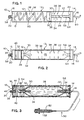
- An ambulatory pump (10) for dispensing a liquid under pressure at a predetermined flow rate comprising:a housing (12);first (14) and second (16) fixed end caps positioned on the housing and enclosing the housing, each of the end caps having a port (18,20) formed therein;a pressurizable bladder (22) defining an interior storage volume (26), the bladder being carried by the housing for receiving and dispensing the liquid, the bladder being expandable between an unexpanded condition and an expanded condition, the bladder having a free end (30) defining an opening in flow communication with the second end cap port (20) and a fixed end (24) defining an opening in flow communication with the first end cap port (18); andflexible tubing (40) carried by the housing, which tubing extends between a port (34) on a moveable element (32) on which the free end of the bladder is mounted and an opening (O) formed by the tubing for filling the bladder, wherein the flexible tubing provides flow communication between the opening (O) and the port (34).
- The ambulatory pump in accordance with claim 1 wherein the opening (O) formed by the flexible tubing for filling the bladder with liquid is connected to and in flow communication with a port (20) on the second end cap (16).
- The ambulatory pump in accordance with claim 1 wherein the moveable element (32) positioned between the flexible tubing (40) and the bladder (22), is longitudinally movable within the housing (12) as the bladder moves between the expanded condition and the unexpanded condition.
- The ambulatory pump in accordance with claim 3 wherein the housing (12) is formed of a transparent material.
- The ambulatory pump in accordance with claim 4 wherein the moveable element (32) is an indicator and includes indicia (36) thereon, and wherein the housing (12) includes indicia (38) which, in cooperation with the indicia on the indicator indicates a determinable volume of fluid in the pump.
- The ambulatory pump in accordance with claim 1 wherein one of the end caps (14,16) includes a vent opening (42).
- The ambulatory pump in accordance with claim 6 wherein the vent opening (42) includes a covering formed of a hydrophobic material (44).
- The ambulatory pump in accordance with claim 1 including a tubing set (50) connected to the pump at the first end cap port (18), the tubing set including a flow restrictor (52).
Applications Claiming Priority (3)
| Application Number | Priority Date | Filing Date | Title |
|---|---|---|---|
| US997787 | 1997-12-24 | ||
| US08/997,787 US5897530A (en) | 1997-12-24 | 1997-12-24 | Enclosed ambulatory pump |
| PCT/US1998/024316 WO1999033503A1 (en) | 1997-12-24 | 1998-11-13 | Enclosed ambulatory pump |
Publications (2)
| Publication Number | Publication Date |
|---|---|
| EP0944405A1 EP0944405A1 (en) | 1999-09-29 |
| EP0944405B1 true EP0944405B1 (en) | 2002-02-13 |
Family
ID=25544397
Family Applications (1)
| Application Number | Title | Priority Date | Filing Date |
|---|---|---|---|
| EP98957949A Expired - Lifetime EP0944405B1 (en) | 1997-12-24 | 1998-11-13 | Enclosed ambulatory pump |
Country Status (12)
| Country | Link |
|---|---|
| US (1) | US5897530A (en) |
| EP (1) | EP0944405B1 (en) |
| JP (1) | JP3260388B2 (en) |
| KR (1) | KR100540965B1 (en) |
| CN (1) | CN1152720C (en) |
| AT (1) | ATE213171T1 (en) |
| DE (1) | DE69803831T2 (en) |
| DK (1) | DK0944405T3 (en) |
| ES (1) | ES2173645T3 (en) |
| PT (1) | PT944405E (en) |
| TW (1) | TW374733B (en) |
| WO (1) | WO1999033503A1 (en) |
Cited By (1)
| Publication number | Priority date | Publication date | Assignee | Title |
|---|---|---|---|---|
| EP1746479A1 (en) | 2005-07-22 | 2007-01-24 | RoweMed AG - Medical 4 Life | Mechanically operated liquid pump |
Families Citing this family (156)
| Publication number | Priority date | Publication date | Assignee | Title |
|---|---|---|---|---|
| JP3207799B2 (en) * | 1997-12-03 | 2001-09-10 | 株式会社パイオラックス | Continuous chemical injector |
| US6183461B1 (en) | 1998-03-11 | 2001-02-06 | Situs Corporation | Method for delivering a medication |
| US6348043B1 (en) * | 1998-12-29 | 2002-02-19 | Mckinley Medical, Lllp | Multi-dose infusion pump providing minimal flow between doses |
| WO2000071189A1 (en) * | 1999-05-21 | 2000-11-30 | Mallinckrodt Inc. | Contrast media resuspension device and method |
| US6554792B2 (en) * | 1999-05-21 | 2003-04-29 | Mallinckrodt Inc. | Suspension device and method |
| WO2001056634A1 (en) * | 2000-02-03 | 2001-08-09 | Medtronic, Inc. | Variable infusion rate catheter |
| US6485461B1 (en) * | 2000-04-04 | 2002-11-26 | Insulet, Inc. | Disposable infusion device |
| US6544229B1 (en) | 2000-05-01 | 2003-04-08 | Baxter International Inc | Linearly motile infusion pump |
| ES2287156T3 (en) * | 2000-09-08 | 2007-12-16 | Insulet Corporation | DEVICES AND SYSTEMS FOR THE INFUSION OF A PATIENT. |
| US6669669B2 (en) * | 2001-10-12 | 2003-12-30 | Insulet Corporation | Laminated patient infusion device |
| US6699218B2 (en) | 2000-11-09 | 2004-03-02 | Insulet Corporation | Transcutaneous delivery means |
| DE60115707T2 (en) | 2000-12-21 | 2006-08-10 | Insulet Corp., Beverly | REMOTE CONTROL MEDICAL DEVICE |
| US6749581B2 (en) | 2001-02-02 | 2004-06-15 | Medtronic, Inc. | Variable infusion rate catheter |
| US6562000B2 (en) | 2001-02-02 | 2003-05-13 | Medtronic, Inc. | Single-use therapeutic substance delivery device with infusion rate control |
| CN1556716A (en) | 2001-02-22 | 2004-12-22 | ���Ͽع�����˾ | Modular infusion device and method |
| US20040078028A1 (en) * | 2001-11-09 | 2004-04-22 | Flaherty J. Christopher | Plunger assembly for patient infusion device |
| US10173008B2 (en) | 2002-01-29 | 2019-01-08 | Baxter International Inc. | System and method for communicating with a dialysis machine through a network |
| US8775196B2 (en) | 2002-01-29 | 2014-07-08 | Baxter International Inc. | System and method for notification and escalation of medical data |
| US6830558B2 (en) | 2002-03-01 | 2004-12-14 | Insulet Corporation | Flow condition sensor assembly for patient infusion device |
| US6692457B2 (en) * | 2002-03-01 | 2004-02-17 | Insulet Corporation | Flow condition sensor assembly for patient infusion device |
| US20040153032A1 (en) * | 2002-04-23 | 2004-08-05 | Garribotto John T. | Dispenser for patient infusion device |
| US6656158B2 (en) | 2002-04-23 | 2003-12-02 | Insulet Corporation | Dispenser for patient infusion device |
| US20050238507A1 (en) * | 2002-04-23 | 2005-10-27 | Insulet Corporation | Fluid delivery device |
| US6656159B2 (en) | 2002-04-23 | 2003-12-02 | Insulet Corporation | Dispenser for patient infusion device |
| JP3854190B2 (en) * | 2002-04-26 | 2006-12-06 | 株式会社ジェイテクト | Motor control device |
| US8234128B2 (en) | 2002-04-30 | 2012-07-31 | Baxter International, Inc. | System and method for verifying medical device operational parameters |
| US6723072B2 (en) | 2002-06-06 | 2004-04-20 | Insulet Corporation | Plunger assembly for patient infusion device |
| US7018361B2 (en) | 2002-06-14 | 2006-03-28 | Baxter International Inc. | Infusion pump |
| US7018360B2 (en) * | 2002-07-16 | 2006-03-28 | Insulet Corporation | Flow restriction system and method for patient infusion device |
| AU2002950421A0 (en) * | 2002-07-29 | 2002-09-12 | Combined Resource Engineering Pty Ltd | Fluid operating pump |
| US7128727B2 (en) * | 2002-09-30 | 2006-10-31 | Flaherty J Christopher | Components and methods for patient infusion device |
| US7144384B2 (en) * | 2002-09-30 | 2006-12-05 | Insulet Corporation | Dispenser components and methods for patient infusion device |
| US9055995B2 (en) * | 2002-11-04 | 2015-06-16 | Aspire Bariatrics, Inc. | Method for treating obesity by extracting food |
| US7740624B2 (en) * | 2002-11-04 | 2010-06-22 | Aspiration Medical Technology, Llc | Method for treating obesity by extracting food |
| US7815629B2 (en) | 2002-11-04 | 2010-10-19 | Deka Products Limited Partnership | Apparatus for treating obesity by extracting food |
| CN100376294C (en) * | 2002-11-08 | 2008-03-26 | 山东威高集团医用高分子制品股份有限公司 | Precision antalgic transfusion device |
| US20040116866A1 (en) * | 2002-12-17 | 2004-06-17 | William Gorman | Skin attachment apparatus and method for patient infusion device |
| US7341572B2 (en) * | 2003-02-28 | 2008-03-11 | Baxter International Inc. | Infusor with flexible sheath |
| US6892755B2 (en) * | 2003-02-28 | 2005-05-17 | Baxter International Inc. | Pressure regulator for infusor |
| US20040206771A1 (en) * | 2003-04-18 | 2004-10-21 | Eric Junkel | Water toy with two port elastic fluid bladder |
| US20050182366A1 (en) * | 2003-04-18 | 2005-08-18 | Insulet Corporation | Method For Visual Output Verification |
| US7169128B2 (en) * | 2003-08-04 | 2007-01-30 | Bioquiddity, Inc. | Multichannel fluid delivery device |
| US7220244B2 (en) * | 2003-08-04 | 2007-05-22 | Bioquiddity, Inc. | Infusion apparatus with constant force spring energy source |
| US20050033232A1 (en) * | 2003-08-05 | 2005-02-10 | Kriesel Marshall S. | Infusion apparatus with modulated flow control |
| US20050065760A1 (en) * | 2003-09-23 | 2005-03-24 | Robert Murtfeldt | Method for advising patients concerning doses of insulin |
| US20050070847A1 (en) * | 2003-09-29 | 2005-03-31 | Van Erp Wilhelmus Petrus Martinus Maria | Rapid-exchange balloon catheter with hypotube shaft |
| TW200529900A (en) * | 2004-02-12 | 2005-09-16 | Nipro Corp | Medicine liquid injector with weight measurer |
| US20070156090A1 (en) * | 2004-05-26 | 2007-07-05 | Kriesel Marshall S | Fluid delivery apparatus |
| US7220245B2 (en) * | 2004-05-26 | 2007-05-22 | Kriesel Marshall S | Infusion apparatus |
| US20050277884A1 (en) * | 2004-05-26 | 2005-12-15 | Kriesel Marshall S | Fluid delivery apparatus with bellows reservoir |
| US7470253B2 (en) * | 2004-05-26 | 2008-12-30 | Bioquiddity, Inc. | Fluid delivery apparatus with adjustable flow rate control |
| US20050277883A1 (en) * | 2004-05-26 | 2005-12-15 | Kriesel Marshall S | Fluid delivery device |
| US20050267413A1 (en) * | 2004-05-26 | 2005-12-01 | Wang Jong H | Flow monitoring devices and methods of use |
| US20060178633A1 (en) * | 2005-02-03 | 2006-08-10 | Insulet Corporation | Chassis for fluid delivery device |
| US8029468B2 (en) * | 2005-02-15 | 2011-10-04 | Bioquiddity, Inc. | Fluid delivery and mixing apparatus with flow rate control |
| US7694938B2 (en) * | 2005-02-17 | 2010-04-13 | Bioquiddity, Inc. | Distal rate control device |
| US20080009835A1 (en) * | 2005-02-17 | 2008-01-10 | Kriesel Marshall S | Fluid dispensing apparatus with flow rate control |
| US7837653B2 (en) * | 2005-02-18 | 2010-11-23 | Bioquiddity, Inc. | Fluid delivery apparatus with vial fill |
| JP5586845B2 (en) * | 2005-04-25 | 2014-09-10 | インテグリス・インコーポレーテッド | Method and apparatus for processing fluid to reduce microbubbles |
| US7552240B2 (en) * | 2005-05-23 | 2009-06-23 | International Business Machines Corporation | Method for user space operations for direct I/O between an application instance and an I/O adapter |
| US7828772B2 (en) | 2006-03-15 | 2010-11-09 | Bioquiddity, Inc. | Fluid dispensing device |
| US7993304B2 (en) * | 2006-03-15 | 2011-08-09 | Bioquiddity, Inc. | Fluid dispensing apparatus |
| US20110082442A1 (en) * | 2006-07-05 | 2011-04-07 | Solovay Kenneth S | Externally reinforced percutaneous gastrostomy tube with customizable smooth tube length |
| US20080091146A1 (en) * | 2006-07-05 | 2008-04-17 | Aspiration Medical Technology, Llc | Shunt apparatus for treating obesity by extracting food |
| US8057435B2 (en) | 2006-07-31 | 2011-11-15 | Kriesel Joshua W | Fluid dispenser |
| US8292848B2 (en) * | 2006-07-31 | 2012-10-23 | Bio Quiddity, Inc. | Fluid dispensing device with additive |
| US8632513B2 (en) * | 2006-08-03 | 2014-01-21 | Aspire Bariatrics, Inc. | Systems and methods for removing ingested material from a stomach |
| US8414561B2 (en) | 2006-08-03 | 2013-04-09 | Aspire Bariatrics, Llc | Systems and methods for removing ingested material from a stomach |
| US9056164B2 (en) | 2007-01-01 | 2015-06-16 | Bayer Medical Care Inc. | Radiopharmaceutical administration methods, fluid delivery systems and components thereof |
| US20080243077A1 (en) * | 2007-04-02 | 2008-10-02 | Bivin Donald B | Fluid dispenser with uniformly collapsible reservoir |
| US7892213B2 (en) * | 2007-04-20 | 2011-02-22 | Carefusion 303, Inc. | Fluid flow control system having capillary fluid flow restrictor |
| US20080319385A1 (en) * | 2007-06-25 | 2008-12-25 | Kriesel Marshall S | Fluid dispenser with additive sub-system |
| US8211059B2 (en) * | 2007-06-25 | 2012-07-03 | Kriesel Marshall S | Fluid dispenser with additive sub-system |
| US20090093774A1 (en) * | 2007-10-04 | 2009-04-09 | Baxter International Inc. | Ambulatory pump with intelligent flow control |
| US8215157B2 (en) * | 2007-10-04 | 2012-07-10 | Baxter International Inc. | System and method for measuring liquid viscosity in a fluid delivery system |
| DE102007049446A1 (en) * | 2007-10-16 | 2009-04-23 | Cequr Aps | Catheter introducer |
| US8986253B2 (en) | 2008-01-25 | 2015-03-24 | Tandem Diabetes Care, Inc. | Two chamber pumps and related methods |
| US8057679B2 (en) | 2008-07-09 | 2011-11-15 | Baxter International Inc. | Dialysis system having trending and alert generation |
| US10089443B2 (en) | 2012-05-15 | 2018-10-02 | Baxter International Inc. | Home medical device systems and methods for therapy prescription and tracking, servicing and inventory |
| US7959598B2 (en) | 2008-08-20 | 2011-06-14 | Asante Solutions, Inc. | Infusion pump systems and methods |
| WO2010030602A1 (en) * | 2008-09-09 | 2010-03-18 | Baxter International Inc. | Device to indicate priming of an infusion line |
| US8408421B2 (en) | 2008-09-16 | 2013-04-02 | Tandem Diabetes Care, Inc. | Flow regulating stopcocks and related methods |
| US8650937B2 (en) | 2008-09-19 | 2014-02-18 | Tandem Diabetes Care, Inc. | Solute concentration measurement device and related methods |
| US8554579B2 (en) | 2008-10-13 | 2013-10-08 | Fht, Inc. | Management, reporting and benchmarking of medication preparation |
| US8105269B2 (en) | 2008-10-24 | 2012-01-31 | Baxter International Inc. | In situ tubing measurements for infusion pumps |
| US8316897B2 (en) * | 2009-01-25 | 2012-11-27 | Mattel, Inc. | Water gun assembly |
| US8353864B2 (en) * | 2009-02-18 | 2013-01-15 | Davis David L | Low cost disposable infusion pump |
| US20100211002A1 (en) * | 2009-02-18 | 2010-08-19 | Davis David L | Electromagnetic infusion pump with integral flow monitor |
| US8197235B2 (en) * | 2009-02-18 | 2012-06-12 | Davis David L | Infusion pump with integrated permanent magnet |
| US8137083B2 (en) | 2009-03-11 | 2012-03-20 | Baxter International Inc. | Infusion pump actuators, system and method for controlling medical fluid flowrate |
| EP2724739B1 (en) | 2009-07-30 | 2015-07-01 | Tandem Diabetes Care, Inc. | Portable infusion pump system |
| US8547239B2 (en) | 2009-08-18 | 2013-10-01 | Cequr Sa | Methods for detecting failure states in a medicine delivery device |
| US8672873B2 (en) * | 2009-08-18 | 2014-03-18 | Cequr Sa | Medicine delivery device having detachable pressure sensing unit |
| US8382447B2 (en) | 2009-12-31 | 2013-02-26 | Baxter International, Inc. | Shuttle pump with controlled geometry |
| NL1037733C2 (en) * | 2010-02-22 | 2011-08-23 | Yusuf Galipoglu | PORTABLE MECHANICAL CAN FOR LIQUID FABRIC AND INFUSION SYSTEM. |
| US9108047B2 (en) | 2010-06-04 | 2015-08-18 | Bayer Medical Care Inc. | System and method for planning and monitoring multi-dose radiopharmaceutical usage on radiopharmaceutical injectors |
| US8567235B2 (en) | 2010-06-29 | 2013-10-29 | Baxter International Inc. | Tube measurement technique using linear actuator and pressure sensor |
| US9211378B2 (en) | 2010-10-22 | 2015-12-15 | Cequr Sa | Methods and systems for dosing a medicament |
| EP3549524B1 (en) | 2012-03-30 | 2023-01-25 | Insulet Corporation | Fluid delivery device with transcutaneous access tool, insertion mechanism and blood glucose monitoring for use therewith |
| US9180242B2 (en) | 2012-05-17 | 2015-11-10 | Tandem Diabetes Care, Inc. | Methods and devices for multiple fluid transfer |
| US9555186B2 (en) | 2012-06-05 | 2017-01-31 | Tandem Diabetes Care, Inc. | Infusion pump system with disposable cartridge having pressure venting and pressure feedback |
| CN103536982A (en) * | 2012-07-13 | 2014-01-29 | 江苏先声药业有限公司 | Recombinant human endostatin continuous infusion system |
| KR20150048816A (en) | 2012-08-31 | 2015-05-07 | 백스터 코포레이션 잉글우드 | Medication requisition fulfillment system and method |
| KR101974258B1 (en) | 2012-10-26 | 2019-04-30 | 백스터 코포레이션 잉글우드 | Improved image acquisition for medical dose preparation system |
| US9375079B2 (en) | 2012-10-26 | 2016-06-28 | Baxter Corporation Englewood | Work station for medical dose preparation system |
| US20140155829A1 (en) * | 2012-11-30 | 2014-06-05 | Seik Oh | Disposable ambulatory infusion pump having telescopic housing |
| AU2014218794B2 (en) | 2013-02-23 | 2018-03-08 | Aspire Bariatrics, Inc. | Apparatus and method for draining material from a stomach |
| US9173998B2 (en) | 2013-03-14 | 2015-11-03 | Tandem Diabetes Care, Inc. | System and method for detecting occlusions in an infusion pump |
| US9603995B2 (en) * | 2013-03-15 | 2017-03-28 | Tandem Diabetes Care. Inc. | Device and method for setting therapeutic parameters for an infusion device |
| HUE059908T2 (en) * | 2013-06-18 | 2023-01-28 | Enable Injections Inc | Vial transfer and injection apparatus and method |
| ITBO20130338A1 (en) * | 2013-06-28 | 2014-12-29 | Raffaele Longo | CATHETER |
| CN105013043B (en) * | 2014-05-03 | 2017-12-26 | 上海市第一人民医院 | Miniature automatic constant-pressure transfusion device |
| JP2017525032A (en) | 2014-06-30 | 2017-08-31 | バクスター・コーポレーション・イングルウッドBaxter Corporation Englewood | Managed medical information exchange |
| US11575673B2 (en) | 2014-09-30 | 2023-02-07 | Baxter Corporation Englewood | Central user management in a distributed healthcare information management system |
| US11107574B2 (en) | 2014-09-30 | 2021-08-31 | Baxter Corporation Englewood | Management of medication preparation with formulary management |
| JP6593671B2 (en) * | 2014-11-10 | 2019-10-23 | 株式会社塚田メディカル・リサーチ | Liquid supply device |
| WO2016090091A1 (en) | 2014-12-05 | 2016-06-09 | Baxter Corporation Englewood | Dose preparation data analytics |
| SG11201707114XA (en) | 2015-03-03 | 2017-09-28 | Baxter Corp Englewood | Pharmacy workflow management with integrated alerts |
| WO2016207206A1 (en) | 2015-06-25 | 2016-12-29 | Gambro Lundia Ab | Medical device system and method having a distributed database |
| JP6853196B2 (en) * | 2015-06-29 | 2021-03-31 | フィリップ・モーリス・プロダクツ・ソシエテ・アノニム | Cartridge for aerosol generation system |
| EP3320930B1 (en) * | 2015-07-08 | 2021-03-03 | Cebika Inc. | Balloon infuser |
| EP3380061A4 (en) | 2015-11-24 | 2019-07-24 | Insulet Corporation | Wearable automated medication delivery system |
| WO2017091584A1 (en) | 2015-11-25 | 2017-06-01 | Insulet Corporation | Wearable medication delivery device |
| EP3374905A1 (en) | 2016-01-13 | 2018-09-19 | Bigfoot Biomedical, Inc. | User interface for diabetes management system |
| CN112933333B (en) | 2016-01-14 | 2023-03-28 | 比格福特生物医药公司 | Adjusting insulin delivery rate |
| EP3871708A3 (en) | 2016-05-26 | 2022-01-19 | Insulet Corporation | Wearable drug delivery system comprising a prefilled cartridge |
| ITUA20163823A1 (en) * | 2016-05-26 | 2017-11-26 | Adria Med S R L | DEVICE FOR THE INFUSION OF MEDICAL SOLUTIONS |
| WO2018031891A1 (en) | 2016-08-12 | 2018-02-15 | Insulet Corporation | Plunger for drug delivery device |
| WO2018035032A1 (en) | 2016-08-14 | 2018-02-22 | Insulet Corporation | Automatic drug delivery device with trigger mechanism |
| US10751478B2 (en) | 2016-10-07 | 2020-08-25 | Insulet Corporation | Multi-stage delivery system |
| US11946466B2 (en) * | 2016-10-27 | 2024-04-02 | Baxter International Inc. | Medical fluid therapy machine including pneumatic pump box and accumulators therefore |
| US10780217B2 (en) | 2016-11-10 | 2020-09-22 | Insulet Corporation | Ratchet drive for on body delivery system |
| WO2018096534A1 (en) | 2016-11-22 | 2018-05-31 | Sorrel Medical Ltd. | Apparatus for delivering a therapeutic substance |
| KR102476516B1 (en) | 2016-12-21 | 2022-12-09 | 감브로 룬디아 아베 | A medical device system that includes an information technology infrastructure with secure cluster domains supporting external domains. |
| US10603440B2 (en) | 2017-01-19 | 2020-03-31 | Insulet Corporation | Cartridge hold-up volume reduction |
| US11045603B2 (en) | 2017-02-22 | 2021-06-29 | Insulet Corporation | Needle insertion mechanisms for drug containers |
| US10695485B2 (en) | 2017-03-07 | 2020-06-30 | Insulet Corporation | Very high volume user filled drug delivery device |
| US20200222281A1 (en) * | 2017-07-17 | 2020-07-16 | Baxter International Inc. | Sterile Product Bag with Filtered Port |
| US11280327B2 (en) | 2017-08-03 | 2022-03-22 | Insulet Corporation | Micro piston pump |
| US10973978B2 (en) | 2017-08-03 | 2021-04-13 | Insulet Corporation | Fluid flow regulation arrangements for drug delivery devices |
| KR101834787B1 (en) * | 2017-08-31 | 2018-04-13 | 제이에스케이바이오메드(주) | Micro-jet drug delivery device with reciprocating disk |
| US11786668B2 (en) | 2017-09-25 | 2023-10-17 | Insulet Corporation | Drug delivery devices, systems, and methods with force transfer elements |
| US10898656B2 (en) | 2017-09-26 | 2021-01-26 | Insulet Corporation | Needle mechanism module for drug delivery device |
| US11147931B2 (en) | 2017-11-17 | 2021-10-19 | Insulet Corporation | Drug delivery device with air and backflow elimination |
| USD928199S1 (en) | 2018-04-02 | 2021-08-17 | Bigfoot Biomedical, Inc. | Medication delivery device with icons |
| US10874803B2 (en) | 2018-05-31 | 2020-12-29 | Insulet Corporation | Drug cartridge with drive system |
| US11229736B2 (en) | 2018-06-06 | 2022-01-25 | Insulet Corporation | Linear shuttle pump for drug delivery |
| WO2020036964A1 (en) * | 2018-08-13 | 2020-02-20 | 410 Medical, Inc. | Systems, apparatus, and methods for reducing fluid pressure in a fluid line |
| EP3744368A1 (en) | 2018-10-05 | 2020-12-02 | Sorrel Medical Ltd. | Triggering sequence |
| US11446435B2 (en) | 2018-11-28 | 2022-09-20 | Insulet Corporation | Drug delivery shuttle pump system and valve assembly |
| USD920343S1 (en) | 2019-01-09 | 2021-05-25 | Bigfoot Biomedical, Inc. | Display screen or portion thereof with graphical user interface associated with insulin delivery |
| US11369735B2 (en) | 2019-11-05 | 2022-06-28 | Insulet Corporation | Component positioning of a linear shuttle pump |
| CN110965615B (en) * | 2019-12-21 | 2021-02-02 | 程小燕 | Toilet urinal flushing device |
| US11951284B2 (en) | 2020-08-27 | 2024-04-09 | Tandem Diabetes Care, Inc. | Transitioning to other modes in automated insulin delivery |
| US11311666B1 (en) | 2021-02-18 | 2022-04-26 | Fresenius Kabi Deutschland Gmbh | Modular wearable medicament delivery device and method of use thereof |
| US11464902B1 (en) * | 2021-02-18 | 2022-10-11 | Fresenius Kabi Deutschland Gmbh | Wearable medicament delivery device with compressible reservoir and method of use thereof |
Family Cites Families (28)
| Publication number | Priority date | Publication date | Assignee | Title |
|---|---|---|---|---|
| US3760806A (en) * | 1971-01-13 | 1973-09-25 | Alza Corp | Helical osmotic dispenser with non-planar membrane |
| US4201207A (en) * | 1973-03-26 | 1980-05-06 | Alza Corporation | Bladder for liquid dispenser |
| US4318400A (en) * | 1980-01-18 | 1982-03-09 | Alza Corporation | Medical infusor |
| US4386929A (en) * | 1980-01-18 | 1983-06-07 | Alza Corporation | Elastomeric bladder assembly |
| US4419096A (en) * | 1982-02-22 | 1983-12-06 | Alza Corporation | Elastomeric bladder assembly |
| DE211850T1 (en) * | 1985-01-07 | 1988-06-30 | Baxter Travenol Laboratories, Inc., Deerfield, Ill., Us | INFUSION DEVICE WITH FLOW CONTROLLER AT ITS DISTAL END. |
| US4741733A (en) * | 1985-01-07 | 1988-05-03 | Baxter Travenol Laboratories, Inc. | Infusor having a distal flow regulator |
| US4904239A (en) * | 1985-01-07 | 1990-02-27 | Baxter International Inc. | Infusor having a distal flow regulator |
| JPS63501195A (en) * | 1985-08-06 | 1988-05-12 | バクスター、インターナショナル、インコーポレイテッド | Device for patient-controlled release of beneficial drugs |
| US4769008A (en) * | 1986-11-26 | 1988-09-06 | Infusion Systems Corporation | Pressurized fluid dispenser |
| US4909790A (en) * | 1987-06-18 | 1990-03-20 | Nissho Corporation | Liquid infusion device |
| JPH0687896B2 (en) * | 1987-11-20 | 1994-11-09 | 株式会社ニッショー | Balloon infusor |
| US5080652A (en) * | 1989-10-31 | 1992-01-14 | Block Medical, Inc. | Infusion apparatus |
| CA2053854C (en) * | 1990-02-28 | 1999-07-13 | Osamu Tsukada | Infuser with balloon for continuously infusing solution of medicine |
| US5137175A (en) * | 1990-02-28 | 1992-08-11 | Gmi Engineering & Management Institute | Fluid storing and dispensing |
| US5178610A (en) * | 1990-07-05 | 1993-01-12 | Nissho Corporation | Liquid infusion device |
| US5083678A (en) * | 1990-08-27 | 1992-01-28 | James River Corporation | Collapsible dispenser bottle |
| WO1992006721A1 (en) * | 1990-10-23 | 1992-04-30 | Industrias Palex, S.A. | Portable pressure infusion device for medicinal solutions |
| FR2672803A1 (en) * | 1991-02-15 | 1992-08-21 | Renaudeaux Jean Pierre | Device for injecting medicaments in liquid phase |
| US5135497A (en) * | 1991-07-08 | 1992-08-04 | Baxter International Inc. | Large volume pressurized fluid dispenser |
| US5298025A (en) * | 1991-07-08 | 1994-03-29 | Baxter International Inc. | Sequential flow rate infusion rate |
| US5224934A (en) * | 1991-12-06 | 1993-07-06 | Block Medical, Inc. | Patient controlled bolus dosage infuser |
| US5263940A (en) * | 1992-04-17 | 1993-11-23 | Science Incorporated | Fluid dispenser |
| US5354278A (en) * | 1992-04-17 | 1994-10-11 | Science Incorporated | Fluid dispenser |
| US5484415A (en) * | 1992-04-17 | 1996-01-16 | Science Incorporated | Fluid dispensing apparatus |
| JP3259267B2 (en) * | 1993-12-28 | 2002-02-25 | ニプロ株式会社 | Chemical injection device |
| JP3499317B2 (en) * | 1995-01-24 | 2004-02-23 | オーベクス株式会社 | Liquid supply device |
| DE69531547T2 (en) * | 1995-06-06 | 2004-06-17 | Tsukada Medical Research Co., Ltd. | PORTABLE PAIN RELIEF DEVICE |
-
1997
- 1997-12-24 US US08/997,787 patent/US5897530A/en not_active Expired - Fee Related
-
1998
- 1998-11-13 JP JP53496599A patent/JP3260388B2/en not_active Expired - Fee Related
- 1998-11-13 KR KR1019997001288A patent/KR100540965B1/en not_active IP Right Cessation
- 1998-11-13 PT PT98957949T patent/PT944405E/en unknown
- 1998-11-13 DE DE69803831T patent/DE69803831T2/en not_active Expired - Lifetime
- 1998-11-13 WO PCT/US1998/024316 patent/WO1999033503A1/en active IP Right Grant
- 1998-11-13 CN CNB988011239A patent/CN1152720C/en not_active Expired - Fee Related
- 1998-11-13 EP EP98957949A patent/EP0944405B1/en not_active Expired - Lifetime
- 1998-11-13 ES ES98957949T patent/ES2173645T3/en not_active Expired - Lifetime
- 1998-11-13 AT AT98957949T patent/ATE213171T1/en active
- 1998-11-13 DK DK98957949T patent/DK0944405T3/en active
- 1998-11-17 TW TW087118991A patent/TW374733B/en not_active IP Right Cessation
Cited By (1)
| Publication number | Priority date | Publication date | Assignee | Title |
|---|---|---|---|---|
| EP1746479A1 (en) | 2005-07-22 | 2007-01-24 | RoweMed AG - Medical 4 Life | Mechanically operated liquid pump |
Also Published As
| Publication number | Publication date |
|---|---|
| DE69803831T2 (en) | 2002-10-31 |
| CN1152720C (en) | 2004-06-09 |
| EP0944405A1 (en) | 1999-09-29 |
| US5897530A (en) | 1999-04-27 |
| KR100540965B1 (en) | 2006-01-10 |
| WO1999033503A1 (en) | 1999-07-08 |
| DK0944405T3 (en) | 2002-04-02 |
| JP3260388B2 (en) | 2002-02-25 |
| JP2000510383A (en) | 2000-08-15 |
| ATE213171T1 (en) | 2002-02-15 |
| ES2173645T3 (en) | 2002-10-16 |
| PT944405E (en) | 2002-07-31 |
| TW374733B (en) | 1999-11-21 |
| DE69803831D1 (en) | 2002-03-21 |
| CN1236325A (en) | 1999-11-24 |
| KR20000068176A (en) | 2000-11-25 |
Similar Documents
| Publication | Publication Date | Title |
|---|---|---|
| EP0944405B1 (en) | Enclosed ambulatory pump | |
| EP0032792B1 (en) | Medical infusor | |
| US4386929A (en) | Elastomeric bladder assembly | |
| EP0290586B1 (en) | Pressurized fluid dispenser | |
| US5607418A (en) | Implantable drug delivery apparatus | |
| US5188603A (en) | Fluid infusion delivery system | |
| US5135500A (en) | Self-driven pump device | |
| US4909790A (en) | Liquid infusion device | |
| AU697014B2 (en) | Syringe for infusion | |
| US4474575A (en) | Self-driven pump assembly and method of operation | |
| US4834705A (en) | Drug dispensing system | |
| US5120315A (en) | Pressurized fluid dispenser | |
| US5873857A (en) | Fluid dispenser with fill adapter | |
| US6059747A (en) | Syringe pump infusion control set | |
| US6245041B1 (en) | Fluid dispenser with fill adapter | |
| US5263935A (en) | Pressurized fluid dispenser | |
| WO1997047339A1 (en) | Gravity infusion set for medical infusions | |
| US5135497A (en) | Large volume pressurized fluid dispenser | |
| AU707645B2 (en) | Fluid administration apparatus | |
| US20200405954A1 (en) | Status Indicator of a Drug Delivery System | |
| CN113164679A (en) | Syringe adapter | |
| CN211357145U (en) | Liquid feeding pump system | |
| EP0810000B1 (en) | Flow rate control device having priming mechanism for injecting liquid medicine | |
| EP0600754A2 (en) | Constant pharmaceutical infuser | |
| WO1989003697A1 (en) | Collapsible solution container |
Legal Events
| Date | Code | Title | Description |
|---|---|---|---|
| PUAI | Public reference made under article 153(3) epc to a published international application that has entered the european phase |
Free format text: ORIGINAL CODE: 0009012 |
|
| 17P | Request for examination filed |
Effective date: 19990219 |
|
| AK | Designated contracting states |
Kind code of ref document: A1 Designated state(s): AT CH DE DK ES FR GB IE IT LI PT SE |
|
| 17Q | First examination report despatched |
Effective date: 20000526 |
|
| GRAG | Despatch of communication of intention to grant |
Free format text: ORIGINAL CODE: EPIDOS AGRA |
|
| GRAG | Despatch of communication of intention to grant |
Free format text: ORIGINAL CODE: EPIDOS AGRA |
|
| GRAG | Despatch of communication of intention to grant |
Free format text: ORIGINAL CODE: EPIDOS AGRA |
|
| GRAH | Despatch of communication of intention to grant a patent |
Free format text: ORIGINAL CODE: EPIDOS IGRA |
|
| GRAH | Despatch of communication of intention to grant a patent |
Free format text: ORIGINAL CODE: EPIDOS IGRA |
|
| GRAA | (expected) grant |
Free format text: ORIGINAL CODE: 0009210 |
|
| REG | Reference to a national code |
Ref country code: GB Ref legal event code: IF02 |
|
| AK | Designated contracting states |
Kind code of ref document: B1 Designated state(s): AT CH DE DK ES FR GB IE IT LI PT SE |
|
| REF | Corresponds to: |
Ref document number: 213171 Country of ref document: AT Date of ref document: 20020215 Kind code of ref document: T |
|
| REG | Reference to a national code |
Ref country code: CH Ref legal event code: EP |
|
| REF | Corresponds to: |
Ref document number: 69803831 Country of ref document: DE Date of ref document: 20020321 |
|
| REG | Reference to a national code |
Ref country code: DK Ref legal event code: T3 |
|
| REG | Reference to a national code |
Ref country code: CH Ref legal event code: NV Representative=s name: KIRKER & CIE SA |
|
| ET | Fr: translation filed | ||
| REG | Reference to a national code |
Ref country code: PT Ref legal event code: SC4A Free format text: AVAILABILITY OF NATIONAL TRANSLATION Effective date: 20020510 |
|
| REG | Reference to a national code |
Ref country code: ES Ref legal event code: FG2A Ref document number: 2173645 Country of ref document: ES Kind code of ref document: T3 |
|
| PLBE | No opposition filed within time limit |
Free format text: ORIGINAL CODE: 0009261 |
|
| STAA | Information on the status of an ep patent application or granted ep patent |
Free format text: STATUS: NO OPPOSITION FILED WITHIN TIME LIMIT |
|
| 26N | No opposition filed |
Effective date: 20021114 |
|
| PGFP | Annual fee paid to national office [announced via postgrant information from national office to epo] |
Ref country code: PT Payment date: 20101026 Year of fee payment: 13 |
|
| REG | Reference to a national code |
Ref country code: PT Ref legal event code: MM4A Free format text: LAPSE DUE TO NON-PAYMENT OF FEES Effective date: 20120514 |
|
| PG25 | Lapsed in a contracting state [announced via postgrant information from national office to epo] |
Ref country code: PT Free format text: LAPSE BECAUSE OF NON-PAYMENT OF DUE FEES Effective date: 20120514 |
|
| REG | Reference to a national code |
Ref country code: FR Ref legal event code: PLFP Year of fee payment: 18 |
|
| REG | Reference to a national code |
Ref country code: FR Ref legal event code: PLFP Year of fee payment: 19 |
|
| PGFP | Annual fee paid to national office [announced via postgrant information from national office to epo] |
Ref country code: IE Payment date: 20161123 Year of fee payment: 19 Ref country code: DK Payment date: 20161123 Year of fee payment: 19 Ref country code: CH Payment date: 20161128 Year of fee payment: 19 |
|
| PGFP | Annual fee paid to national office [announced via postgrant information from national office to epo] |
Ref country code: IT Payment date: 20161124 Year of fee payment: 19 Ref country code: SE Payment date: 20161125 Year of fee payment: 19 |
|
| REG | Reference to a national code |
Ref country code: FR Ref legal event code: PLFP Year of fee payment: 20 |
|
| PGFP | Annual fee paid to national office [announced via postgrant information from national office to epo] |
Ref country code: DE Payment date: 20171129 Year of fee payment: 20 Ref country code: FR Payment date: 20171127 Year of fee payment: 20 |
|
| PGFP | Annual fee paid to national office [announced via postgrant information from national office to epo] |
Ref country code: GB Payment date: 20171127 Year of fee payment: 20 Ref country code: ES Payment date: 20171201 Year of fee payment: 20 Ref country code: AT Payment date: 20171019 Year of fee payment: 20 |
|
| REG | Reference to a national code |
Ref country code: DK Ref legal event code: EBP Effective date: 20171130 |
|
| REG | Reference to a national code |
Ref country code: SE Ref legal event code: EUG |
|
| PG25 | Lapsed in a contracting state [announced via postgrant information from national office to epo] |
Ref country code: LI Free format text: LAPSE BECAUSE OF NON-PAYMENT OF DUE FEES Effective date: 20171130 Ref country code: CH Free format text: LAPSE BECAUSE OF NON-PAYMENT OF DUE FEES Effective date: 20171130 |
|
| PG25 | Lapsed in a contracting state [announced via postgrant information from national office to epo] |
Ref country code: SE Free format text: LAPSE BECAUSE OF NON-PAYMENT OF DUE FEES Effective date: 20171114 |
|
| REG | Reference to a national code |
Ref country code: IE Ref legal event code: MM4A |
|
| PG25 | Lapsed in a contracting state [announced via postgrant information from national office to epo] |
Ref country code: IE Free format text: LAPSE BECAUSE OF NON-PAYMENT OF DUE FEES Effective date: 20171113 Ref country code: IT Free format text: LAPSE BECAUSE OF NON-PAYMENT OF DUE FEES Effective date: 20171113 |
|
| REG | Reference to a national code |
Ref country code: DE Ref legal event code: R071 Ref document number: 69803831 Country of ref document: DE |
|
| PG25 | Lapsed in a contracting state [announced via postgrant information from national office to epo] |
Ref country code: DK Free format text: LAPSE BECAUSE OF NON-PAYMENT OF DUE FEES Effective date: 20171130 |
|
| REG | Reference to a national code |
Ref country code: GB Ref legal event code: PE20 Expiry date: 20181112 |
|
| REG | Reference to a national code |
Ref country code: AT Ref legal event code: MK07 Ref document number: 213171 Country of ref document: AT Kind code of ref document: T Effective date: 20181113 |
|
| PG25 | Lapsed in a contracting state [announced via postgrant information from national office to epo] |
Ref country code: GB Free format text: LAPSE BECAUSE OF EXPIRATION OF PROTECTION Effective date: 20181112 |
|
| REG | Reference to a national code |
Ref country code: ES Ref legal event code: FD2A Effective date: 20201110 |
|
| PG25 | Lapsed in a contracting state [announced via postgrant information from national office to epo] |
Ref country code: ES Free format text: LAPSE BECAUSE OF EXPIRATION OF PROTECTION Effective date: 20181114 |