EP0942401A2 - Method and device for signalling security in traffic light control systems - Google Patents
Method and device for signalling security in traffic light control systems Download PDFInfo
- Publication number
- EP0942401A2 EP0942401A2 EP99104966A EP99104966A EP0942401A2 EP 0942401 A2 EP0942401 A2 EP 0942401A2 EP 99104966 A EP99104966 A EP 99104966A EP 99104966 A EP99104966 A EP 99104966A EP 0942401 A2 EP0942401 A2 EP 0942401A2
- Authority
- EP
- European Patent Office
- Prior art keywords
- actuators
- central unit
- display device
- actual
- state
- Prior art date
- Legal status (The legal status is an assumption and is not a legal conclusion. Google has not performed a legal analysis and makes no representation as to the accuracy of the status listed.)
- Granted
Links
Images
Classifications
-
- G—PHYSICS
- G08—SIGNALLING
- G08G—TRAFFIC CONTROL SYSTEMS
- G08G1/00—Traffic control systems for road vehicles
- G08G1/07—Controlling traffic signals
-
- G—PHYSICS
- G08—SIGNALLING
- G08G—TRAFFIC CONTROL SYSTEMS
- G08G1/00—Traffic control systems for road vehicles
- G08G1/09—Arrangements for giving variable traffic instructions
- G08G1/095—Traffic lights
Definitions
- the invention relates to a method and an apparatus for signal protection in systems with variable message signs according to the preamble of claim 1 or the preamble of claim 3.
- Variable message signs are used to influence traffic used for example on highways.
- the individual traffic signs are arranged by matrix-like Shown points of light that over light guide bundles of low-voltage lamps be illuminated.
- the variable message signs are usually not individually, but in related groups, for example a so-called gantry bridge attached across the road.
- a variable message sign hangs over each lane of the lane. From the individual variable message signs shown states must not conflict trigger, that means they must not contradict each other. Especially must not use dangerous combinations of characters - like two opposing yellow arrows, double images and garbled images appear.
- the displayed The actual status of the traffic signs must therefore be constantly monitored to avoid errors that easily lead to traffic accidents can lead to recognize in time.
- the object is achieved with a method for signal protection with the characterizing features of the claim 1 as well as with a device for signal protection the characterizing features of claim 6 solved.
- a desired state of the central unit in an advantageous manner a selected display device to the associated one Transfer the variable message sign actuator.
- the feedback about the current status of the selected one Display device is used on all actuators as well the central unit transferred.
- each actuator as well as the Central unit will display the actual statuses currently displayed Conflicts with each other checked. It is advantageous each actuator as well as the central unit are able to Display devices, their actual states conflict with each other have to switch to a safe state.
- each actuator checks its associated Display device for a match between Target and actual status and switches in the event of a deviation Display device so that a faulty as early as possible Display is prevented.
- the individual actuators are connected to each other via a control bus, that the feedback about displayed actual conditions to everyone Actuators and the central unit are transmitted. Thereby ensures that all actuators and the central unit the displayed actual states independently of each other can check for conflicts.
- each actuator is assigned switches that have an emergency shutdown circuit switch off between the actuators and the central unit can, as soon as an error between target and actual state occurs.
- the switched off emergency shutdown causes then a shutdown of the operating voltage line for everyone Display devices. This means that there are errors in the actuators ensured that the display devices too actually be turned off.
- the device is particularly simple 8 through control processors operating in the actuators and the central unit are arranged and for transmission and evaluation of the target states and the actual states are.
- the invention is illustrated by the only figure in the drawing explained in more detail.
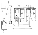
- the figure shows a schematic Circuit diagram of the device for signal protection according to the invention.
- variable message signs 2 schematically two variable message sign 2 shown.
- the variable message signs 2 each have one Display device 3, for example composed of a matrix Illuminated dots illuminated by light guide bundles be, as well as an actuator 4.
- the actuators 4 control the individual display devices 3 and are over a control bus 5 connected to a central unit 6.
- To the The central unit 6 shares the display of a traffic sign Via this control bus 5 an actuator 4 the target state a currently selected display device 3.
- the target state is sent to the selected display device 3 transmitted, which in turn feedback on the displayed Current status is transferred back to the actuators 4.
- For Power supply is provided by an energy supply device 7, the actuators via a line 8 to the power supply 4 and via an operating voltage line 9 the display devices 3 powered.
- control processors 10 which shows the actual states with the target states to be displayed to compare.
- the current status of all variable message signs with the help of a so-called Checked in the actuator 4, signal protection matrix checked.
- the signal protection matrix describes which Actual states are not different at the same time Variable message signers may be displayed (Conflict), so that a traffic hazard is avoided.
- Detected a control processor 10 a deviation of the actual from Desired state or one in the signal protection matrix as dangerous marked combination of actual states (conflict), so at least the display devices involved 3 switched to a safe state, for example they are switched off. In the case of conflict, one will be opposed higher security by switching off everyone in the system 1 arranged display devices 3 achieved.
- an emergency shutdown circuit 11 which connects individual actuators 4 with the central unit 6. There are switches in each actuator and in the central unit 12 provided that are triggered in the event of an error. A switch 13 to interrupt the operating voltage line 9, the is in the emergency shutdown circuit 11, causes in the event of an error an interruption of the operating voltage line 9. This all display devices are switched off. So both a shutdown by the actuators 4 as well as one Shutdown via the operating voltage line 9 ensured.
- the line 8 for Power supply to the actuators 4, the operating voltage line 9, the control bus 5 and the emergency shutdown circuit 11 together in a cable harness from the central unit 6 to the individual variable message signs 2 led.
Landscapes
- Physics & Mathematics (AREA)
- General Physics & Mathematics (AREA)
- Traffic Control Systems (AREA)
- Road Signs Or Road Markings (AREA)
- Inverter Devices (AREA)
- Communication Control (AREA)
- Stereo-Broadcasting Methods (AREA)
Abstract
Description
Die Erfindung bezieht sich auf ein Verfahren sowie eine Vorrichtung
zur Signalsicherung in Systemen mit Wechselverkehrszeichengebern
gemäß dem Oberbegriff des Patentanspruches 1
bzw. dem Oberbegriff des Patentanspruches 3.The invention relates to a method and an apparatus
for signal protection in systems with variable message signs
according to the preamble of
Wechselverkehrszeichen werden zur Beeinflussung des Verkehrs beispielsweise auf Autobahnen eingesetzt. Die einzelnen Verkehrszeichen werden dabei durch matrixartig angeordnete Lichtpunkte dargestellt, die über Lichtleiterbündel von Niedervoltlampen angestrahlt werden. In Abhängigkeit von Verkehrssituationen können dabei unterschiedliche Verkehrszeichen mit einem Wechselverkehrszeichengeber dargestellt werden. Die Wechselverkehrszeichengeber werden meist nicht einzeln, sondern in zusammenhängenden Gruppen beispielsweise an einer sogenannten Schilderbrücke quer über der Fahrbahn angebracht. Über jeder Fahrspur der Fahrbahn hängt dann ein Wechselverkehrszeichengeber. Die von den einzelnen Wechselverkehrszeichengebern gezeigten Zustände dürfen keinen Konflikt auslösen, das heißt sie dürfen sich nicht widersprechen. Insbesondere dürfen keine gefährlichen Zeichenkombinationen - wie zwei gegeneinander weisende Gelbpfeile, Doppelbilder sowie verstümmelte Bilder angezeigt werden. Die angezeigten Istzustände der Verkehrszeichen müssen daher ständig überwacht werden, um auftretende Fehler, die leicht zu Verkehrsunfällen führen können, rechtzeitig zu erkennen.Variable message signs are used to influence traffic used for example on highways. The individual traffic signs are arranged by matrix-like Shown points of light that over light guide bundles of low-voltage lamps be illuminated. Depending on traffic situations can use different traffic signs with a variable message sign. The variable message signs are usually not individually, but in related groups, for example a so-called gantry bridge attached across the road. A variable message sign hangs over each lane of the lane. From the individual variable message signs shown states must not conflict trigger, that means they must not contradict each other. Especially must not use dangerous combinations of characters - like two opposing yellow arrows, double images and garbled images appear. The displayed The actual status of the traffic signs must therefore be constantly monitored to avoid errors that easily lead to traffic accidents can lead to recognize in time.
Aus "Die WVZ- Steuerung von Siemens setzt Maßstäbe", Siemens Grünlicht, Informationen zur Straßenverkehrstechnik, Ausgabe 33, 1994, Seiten 22-26, ist bekannt, daß eine Signalsicherung in einer Streckenstation, die beispielsweise in einem Schaltschrank am Straßenrand angeordnet ist, vorgesehen ist. Die Aufgabe der Signalsicherung ist es dabei, die Auswirkungen elektrotechnischer Fehler der Wechselverkehrszeichensteuerung, der Signalgeber und der Verkabelung auf den Signalisierungszustand zu verhindern. Wesentliche Störungen führen dabei zur Abschaltung des kompletten Anzeigequerschnitts. Um bei der Signalsicherung eine genügend hohe Sicherheit zu gewährleisten, müssen allerdings mindestens zwei Instanzen unabhängig voneinander das angezeigte Bild ständig auf Einhaltung der Regeln überwachen.From "Siemens VMS control sets standards", Siemens Green light, information on road traffic technology, edition 33, 1994, pages 22-26, is known to be a signal fuse in a route station, for example in a control cabinet is arranged on the roadside, is provided. The The task of signal protection is to determine the effects electrotechnical error of variable message sign control, the signal generator and the wiring to the signaling state to prevent. Significant disturbances result to switch off the complete display cross-section. Around to ensure a sufficiently high level of security when securing signals, however, at least two instances must be independent from each other the displayed image is constantly adhering to monitor the rules.
Es ist daher Aufgabe der Erfindung, ein Verfahren und eine Vorrichtung anzugeben, die die Signalsicherung bei einem System mit Wechselverkehrszeichengebern weiter verbessert.It is therefore an object of the invention, a method and a Device to specify the signal protection in a system further improved with variable message signs.
Die Aufgabe wird erfindungsgemäß mit einem Verfahren zur Signalsicherung
mit den kennzeichnenden Merkmalen des Patentanspruchs
1 sowie mit einer Vorrichtung zur Signalsicherung mit
den kennzeichnenden Merkmalen des Patentanspruches 6 gelöst.The object is achieved with a method for signal protection
with the characterizing features of the
Beim Verfahren zur Signalsicherung nach Patentanspruch 1 wird dabei in vorteilhafter Weise von der Zentraleinheit ein Sollzustand einer ausgewählten Anzeigevorrichtung an das zugehörige Stellglied des Wechselverkehrszeichengebers übertragen. Die Rückmeldung über den angezeigten Istzustand der ausgewählten Anzeigevorrichtung wird an alle Stellglieder sowie die Zentraleinheit übertragen. In jedem Stellglied sowie der Zentraleinheit werden die aktuell angezeigten Istzustände auf Konflikte untereinander überprüft. In vorteilhafter Weise ist jedes Stellglied sowie die Zentraleinheit in der Lage, die Anzeigevorrichtungen, deren Istzustände einen Konflikt untereinander aufweisen, in einen sicheren Zustand zu schalten.In the method for signal protection according to claim 1 a desired state of the central unit in an advantageous manner a selected display device to the associated one Transfer the variable message sign actuator. The feedback about the current status of the selected one Display device is used on all actuators as well the central unit transferred. In each actuator as well as the Central unit will display the actual statuses currently displayed Conflicts with each other checked. It is advantageous each actuator as well as the central unit are able to Display devices, their actual states conflict with each other have to switch to a safe state.
In einer weiteren vorteilhaften Ausgestaltung nach Patentanspruch
2 ist zusätzlich vorgesehen, beim Auftreten eines Konflikts
alle Anzeigevorrichtungen in einen sicheren Zustand
zu schalten, damit sichergestellt ist, daß das offensichtlich
fehlerhaft arbeitende System komplett gesichert ist. In a further advantageous embodiment according to
Nach Patentanspruch 3 überprüft jedes Stellglied die ihm zugehörige
Anzeigevorrichtung auf eine Übereinstimmung zwischen
Soll- und Istzustand und schaltet bei einer Abweichung die
Anzeigevorrichtung ab, damit möglichst frühzeitig ein fehlerhafte
Anzeige verhindert wird.According to
Durch Verwendung einer Signalsicherungsmatrix nach Patentanspruch
4, in der die Konflikte zwischen den Istzuständen beschrieben
sind, ist eine besonders übersichtliche Darstellung
der möglichen Konflikte und der darauf zu erfolgenden Reaktionen
sichergestellt. Auch eine Überprüfung der einzelnen
Stellglieder auf die Benutzung einer einheitlichen Signalsicherungsmatrix
ist dadurch vereinfacht.By using a signal protection matrix according to
In der vorteilhaften Ausgestaltung nach Patentanspruch 5 kontrollieren die einzelnen Stellglieder alle anderen Stellglieder auf übereinstimmende Soll- und Istzustände, wodurch eine zusätzliche Sicherheit gegeben ist.Check in the advantageous embodiment according to claim 5 the individual actuators all other actuators to matching target and actual conditions, which means a additional security is given.
In der Vorrichtung zur Durchführung des Verfahrens nach Patentanspruch
6 ist es vorgesehen, daß die einzelnen Stellglieder
über einen Steuerbus so untereinander verbunden sind,
daß die Rückmeldungen über angezeigte Istzustände an alle
Stellglieder und die Zentraleinheit übermittelt werden. Dadurch
ist sichergestellt, daß alle Stellglieder und die Zentraleinheit
unabhängig voneinander die angezeigten Istzustände
auf Konflikte überprüfen können.In the device for performing the method according to
In der vorteilhaften Ausgestaltung nach Patentanspruch 7 sind
jedem Stellglied Schalter zugeordnet, die einen Notabschaltkreis
zwischen den Stellgliedern und der Zentraleinheit abschalten
können, sobald ein Fehler zwischen Soll- und Istzustand
auftritt. Der abgeschaltete Notabschaltkreis bewirkt
dann eine Abschaltung der Betriebsspannungsleitung für alle
Anzeigevorrichtungen. Damit ist bei Fehlern in den Stellgliedern
sichergestellt, daß die Anzeigevorrichtungen auch
tatsächlich abgeschaltet werden. In the advantageous embodiment according to
Besonders einfach gestaltet sich die Vorrichtung nach Patentanspruch 8 durch Steuerprozessoren, die in den Stellgliedern und der Zentraleinheit angeordnet sind und für die Übertragung und Auswertung der Sollzustände und der Istzustände zuständig sind.The device is particularly simple 8 through control processors operating in the actuators and the central unit are arranged and for transmission and evaluation of the target states and the actual states are.
Anhand der einzigen Figur in der Zeichnung wird die Erfindung näher erläutert. Dabei zeigt die Figur schematisch ein Schaltbild der erfindungsgemäßen Vorrichtung zur Signalsicherung.The invention is illustrated by the only figure in the drawing explained in more detail. The figure shows a schematic Circuit diagram of the device for signal protection according to the invention.
In einem System 1 aus Wechselverkehrszeichengebern 2 sind
schematisch zwei Wechselverkehrszeichengeber 2 dargestellt.
Die Wechselverkehrszeichengeber 2 weisen dabei jeweils eine
Anzeigevorrichtung 3, beispielsweise aus matrixartig zusammengesetzten
Leuchtpunkten, die durch Lichtleiterbündel beleuchtet
werden, sowie ein Stellglied 4 auf. Die Stellglieder
4 steuern die einzelnen Anzeigevorrichtungen 3 und sind über
einen Steuerbus 5 mit einer Zentraleinheit 6 verbunden. Zum
Anzeigen eines Verkehrszeichens teilt die Zentraleinheit 6
über diesen Steuerbus 5 einem Stellglied 4 den Sollzustand
einer aktuell ausgewählten Anzeigevorrichtung 3 mit. Der
Sollzustand wird an die ausgewählte Anzeigevorrichtung 3
übermittelt, die ihrerseits Rückmeldungen über den angezeigten
Istzustand an die Stellglieder 4 zurücküberträgt. Zur
Stromversorgung dient eine Energieversorgungseinrichtung 7,
die über eine Leitung 8 zur Stromversorgung die Stellglieder
4 sowie über eine Betriebsspannungsleitung 9 die Anzeigevorrichtungen
3 mit Strom versorgt. In den Stellgliedern 4 sowie
der Zentraleinheit 6 sind Steuerprozessoren 10 vorgesehen,
die die angezeigten Istzustände mit den anzuzeigenden Sollzuständen
vergleichen. Die angezeigten Istzustände aller Wechselverkehrszeichengeber
werden mit Hilfe einer sogenannten,
im Stellglied 4 abgespeicherten, Signalsicherungsmatrix überprüft.
In der Signalsicherungsmatrix ist beschrieben, welche
Istzustände nicht zur gleichen Zeit von unterschiedlichen
Wechselverkehrszeichengebern angezeigt werden dürfen
(Konflikt), damit eine Verkehrsgefährdung vermieden wird. Detektiert
ein Steuerprozessor 10 eine Abweichung des Ist- vom
Sollzustand oder eine in der Signalsicherungsmatrix als gefährlich
markierte Kombination von Istzuständen (Konflikt),
so werden mindestens die daran beteiligten Anzeigevorrichtungen
3 in einen sicheren Zustand geschaltet, beispielsweise
werden sie abgeschaltet. Im Fall des Konflikts wird eine demgegenüber
höhere Sicherheit durch das Abschalten aller im System
1 angeordneten Anzeigevorrichtungen 3 erzielt.In a
Zusätzlich ist ein Notabschaltkreis 11 vorgesehen, der die
einzelnen Stellglieder 4 mit der Zentraleinheit 6 verbindet.
In jedem Stellglied sowie in der Zentraleinheit sind Schalter
12 vorgesehen, die im Fehlerfall ausgelöst werden. Ein Schalter
13 zum Unterbrechen der Betriebsspannungsleitung 9, der
sich im Notabschaltkreis 11 befindet, bewirkt im Fehlerfall
eine Unterbrechung der Betriebsspannungsleitung 9. Dadurch
werden alle Anzeigevorrichtungen abgeschaltet. Somit ist sowohl
eine Abschaltung durch die Stellglieder 4 wie auch eine
Abschaltung über die Betriebsspannungsleitung 9 sichergestellt.
In adernsparender Technik werden die Leitung 8 zur
Stromversorgung der Stellglieder 4 , die Betriebsspannungsleitung
9, der Steuerbus 5 und der Notabschaltkreis 11 gemeinsam
in einem Kabelstrang von der Zentraleinheit 6 zu den
einzelnen Wechselverkehrszeichengebern 2 geführt.In addition, an
Claims (8)
dadurch gekennzeichnet,
characterized,
dadurch gekennzeichnet,
daß die Stellglieder (4) und/oder die Zentraleinheit (6), die den Konflikt zwischen den Istzuständen erkennen, alle Anzeigevorrichtungen (3) in einen sicheren Zustand schalten. Method for securing signals according to claim 1,
characterized,
that the actuators (4) and / or the central unit (6), which recognize the conflict between the actual states, switch all display devices (3) into a safe state.
dadurch gekennzeichnet,
daß das Stellglied (4) den Istzustand mit dem Sollzustand der zugehörigen Anzeigevorrichtung (3) vergleicht und bei einer Abweichung des Istzustands vom Sollzustand die zugehörige Anzeigevorrichtung (3) ausschaltet.Method for signal protection according to one of claims 1 or 2,
characterized,
that the actuator (4) compares the actual state with the target state of the associated display device (3) and switches off the associated display device (3) if the actual state deviates from the target state.
dadurch gekennzeichnet,
daß die Konflikte, die zu einer Abschaltung der wenigstens zwei Anzeigevorrichtungen (3) führen, in einer Signalsicherungsmatrix hinterlegt werden, die in jedem Stellglied (4) und der Zentraleinheit (6) abgespeichert wird.Method for signal protection according to one of claims 1, 2 or 3,
characterized,
that the conflicts that lead to a shutdown of the at least two display devices (3) are stored in a signal protection matrix, which is stored in each actuator (4) and the central unit (6).
dadurch gekennzeichnet,
characterized,
dadurch gekennzeichnet,
daß die Stellglieder (4) über einen Steuerbus (5) untereinander so verbunden sind, daß von den Stellgliedern übermittelte Rückmeldungen über angezeigte Istzustände der jeweils zugehörigen Anzeigevorrichtungen (3) an alle Stellglieder (4) und die Zentraleinheit (6) übermittelt werden.Device for securing signals in systems (1) with variable message sign generators (2), with a central unit (6), which is assigned to variable message sign generators (2), with interconnected actuators (4) and associated display devices (3) in each variable message sign generator (2), the actuators (4) being connected to the central unit (6), and the display devices (3) being connected to an energy supply device (7) via an operating voltage line,
characterized,
that the actuators (4) are connected to one another via a control bus (5) in such a way that feedback transmitted by the actuators about the actual states of the respective associated display devices (3) is transmitted to all actuators (4) and the central unit (6).
dadurch gekennzeichnet,
characterized,
dadurch gekennzeichnet,
daß die Stellglieder (4) und die Zentraleinheit (6) jeweils einen Steuerprozessor (10) für die Übertragung und Auswertung der Sollzustände und der Istzustände aufweisen.Device for securing signals according to one of claims 6 or 7,
characterized,
that the actuators (4) and the central unit (6) each have a control processor (10) for the transmission and evaluation of the target states and the actual states.
Applications Claiming Priority (2)
| Application Number | Priority Date | Filing Date | Title |
|---|---|---|---|
| DE19811082 | 1998-03-13 | ||
| DE19811082 | 1998-03-13 |
Publications (3)
| Publication Number | Publication Date |
|---|---|
| EP0942401A2 true EP0942401A2 (en) | 1999-09-15 |
| EP0942401A3 EP0942401A3 (en) | 2000-08-30 |
| EP0942401B1 EP0942401B1 (en) | 2004-09-22 |
Family
ID=7860880
Family Applications (1)
| Application Number | Title | Priority Date | Filing Date |
|---|---|---|---|
| EP99104966A Expired - Lifetime EP0942401B1 (en) | 1998-03-13 | 1999-03-12 | Method and device for signal safety in traffic light control systems |
Country Status (4)
| Country | Link |
|---|---|
| EP (1) | EP0942401B1 (en) |
| AT (1) | ATE277394T1 (en) |
| DE (1) | DE59910549D1 (en) |
| DK (1) | DK0942401T3 (en) |
Families Citing this family (1)
| Publication number | Priority date | Publication date | Assignee | Title |
|---|---|---|---|---|
| DE102005046760B4 (en) * | 2005-09-29 | 2008-09-04 | Siemens Ag | Method and device for controlling one or more traffic influencing elements |
Citations (4)
| Publication number | Priority date | Publication date | Assignee | Title |
|---|---|---|---|---|
| EP0137964A2 (en) * | 1983-10-17 | 1985-04-24 | Stührenberg, Rolf | Device for signal safety in light sign arrangements |
| DE3541549A1 (en) * | 1985-11-25 | 1987-05-27 | Stuehrenberg Rolf | Method and device for protecting signals in traffic lights |
| EP0330164A2 (en) * | 1988-02-25 | 1989-08-30 | Siemens Aktiengesellschaft | Partial traffic-signalling system disconnecting device |
| FR2647932A1 (en) * | 1989-06-02 | 1990-12-07 | Forclum Force Lumiere Elect | Device for remote monitoring of crossroad traffic lights and method for putting such a device into service |
-
1999
- 1999-03-12 DK DK99104966T patent/DK0942401T3/en active
- 1999-03-12 DE DE59910549T patent/DE59910549D1/en not_active Expired - Fee Related
- 1999-03-12 EP EP99104966A patent/EP0942401B1/en not_active Expired - Lifetime
- 1999-03-12 AT AT99104966T patent/ATE277394T1/en not_active IP Right Cessation
Patent Citations (4)
| Publication number | Priority date | Publication date | Assignee | Title |
|---|---|---|---|---|
| EP0137964A2 (en) * | 1983-10-17 | 1985-04-24 | Stührenberg, Rolf | Device for signal safety in light sign arrangements |
| DE3541549A1 (en) * | 1985-11-25 | 1987-05-27 | Stuehrenberg Rolf | Method and device for protecting signals in traffic lights |
| EP0330164A2 (en) * | 1988-02-25 | 1989-08-30 | Siemens Aktiengesellschaft | Partial traffic-signalling system disconnecting device |
| FR2647932A1 (en) * | 1989-06-02 | 1990-12-07 | Forclum Force Lumiere Elect | Device for remote monitoring of crossroad traffic lights and method for putting such a device into service |
Also Published As
| Publication number | Publication date |
|---|---|
| DE59910549D1 (en) | 2004-10-28 |
| EP0942401B1 (en) | 2004-09-22 |
| DK0942401T3 (en) | 2005-01-24 |
| ATE277394T1 (en) | 2004-10-15 |
| EP0942401A3 (en) | 2000-08-30 |
Similar Documents
| Publication | Publication Date | Title |
|---|---|---|
| DE60023055T2 (en) | Interlocking system for a railway system | |
| EP0082300B1 (en) | Multiplex wiring-system for vehicles | |
| DE19718284C2 (en) | Method and device for monitoring a system with several functional units | |
| WO2010006926A1 (en) | Method and device for operating a railroad security system | |
| EP0330164B1 (en) | Partial traffic-signalling system disconnecting device | |
| DE2701925A1 (en) | VEHICLE CONTROL SYSTEM WITH HIGH RELIABILITY | |
| EP0466694B1 (en) | Process for the provision of cut-out protection for lights in decentralized traffic-light installations | |
| DE102018220092A1 (en) | Method and device for securing automated driving functions | |
| DE3223779A1 (en) | Error-protected light-signal control device with fewer wires | |
| EP0942401B1 (en) | Method and device for signal safety in traffic light control systems | |
| EP0988207B1 (en) | Device for controlling level crossings | |
| EP1420495B1 (en) | Installation of one protection function in an protection apparatus of a power distribution network | |
| DE10052046B4 (en) | Control for rotary printing machines | |
| AT397314B (en) | Traffic warning system | |
| EP3383723A1 (en) | Device and method for controlling and/or monitoring decentralized intelligent functional units arranged in a rail network | |
| DE3219366A1 (en) | Electronic points control | |
| EP2878510B1 (en) | Balise for an automatic train control system, and train safety system with such a balise | |
| EP1002449A1 (en) | Method and device for stabilizing the series circuit current of lighting installations at airports and similar | |
| DE3206082C2 (en) | Fail-safe arrangement for linking the operating status messages from signal lamps | |
| DE3205885C1 (en) | Protection circuit against flashing-light corruption | |
| DE3127363A1 (en) | Computer-controlled signal box | |
| EP3285240B1 (en) | Light sign assembly with an emergency light character signal sensor and method for activating same | |
| DE102014016018B4 (en) | Switching device for an electrical system of a motor vehicle, electrical system and motor vehicle | |
| DE10007896A1 (en) | Control system for airport navigation lights - has central control device connected by bus system to lighting units for control and monitoring | |
| DE102008003439B4 (en) | Traffic signaling module, traffic signaling system and method of operating a traffic signaling system |
Legal Events
| Date | Code | Title | Description |
|---|---|---|---|
| PUAI | Public reference made under article 153(3) epc to a published international application that has entered the european phase |
Free format text: ORIGINAL CODE: 0009012 |
|
| AK | Designated contracting states |
Kind code of ref document: A2 Designated state(s): AT BE CH DE DK LI NL |
|
| AX | Request for extension of the european patent |
Free format text: AL;LT;LV;MK;RO;SI |
|
| PUAL | Search report despatched |
Free format text: ORIGINAL CODE: 0009013 |
|
| AK | Designated contracting states |
Kind code of ref document: A3 Designated state(s): AT BE CH CY DE DK ES FI FR GB GR IE IT LI LU MC NL PT SE |
|
| AX | Request for extension of the european patent |
Free format text: AL;LT;LV;MK;RO;SI |
|
| RIC1 | Information provided on ipc code assigned before grant |
Free format text: 7G 08G 1/07 A, 7G 08G 1/097 B |
|
| 17P | Request for examination filed |
Effective date: 20010219 |
|
| AKX | Designation fees paid |
Free format text: AT BE CH DE DK LI NL |
|
| GRAP | Despatch of communication of intention to grant a patent |
Free format text: ORIGINAL CODE: EPIDOSNIGR1 |
|
| RTI1 | Title (correction) |
Free format text: METHOD AND DEVICE FOR SIGNAL SAFETY IN TRAFFIC LIGHT CONTROL SYSTEMS |
|
| GRAS | Grant fee paid |
Free format text: ORIGINAL CODE: EPIDOSNIGR3 |
|
| GRAA | (expected) grant |
Free format text: ORIGINAL CODE: 0009210 |
|
| AK | Designated contracting states |
Kind code of ref document: B1 Designated state(s): AT BE CH DE DK LI NL |
|
| REG | Reference to a national code |
Ref country code: CH Ref legal event code: NV Representative=s name: SIEMENS SCHWEIZ AG Ref country code: CH Ref legal event code: EP |
|
| REF | Corresponds to: |
Ref document number: 59910549 Country of ref document: DE Date of ref document: 20041028 Kind code of ref document: P |
|
| REG | Reference to a national code |
Ref country code: DK Ref legal event code: T3 |
|
| PG25 | Lapsed in a contracting state [announced via postgrant information from national office to epo] |
Ref country code: LI Free format text: LAPSE BECAUSE OF NON-PAYMENT OF DUE FEES Effective date: 20050331 Ref country code: DK Free format text: LAPSE BECAUSE OF NON-PAYMENT OF DUE FEES Effective date: 20050331 Ref country code: CH Free format text: LAPSE BECAUSE OF NON-PAYMENT OF DUE FEES Effective date: 20050331 Ref country code: BE Free format text: LAPSE BECAUSE OF NON-PAYMENT OF DUE FEES Effective date: 20050331 |
|
| PLBE | No opposition filed within time limit |
Free format text: ORIGINAL CODE: 0009261 |
|
| STAA | Information on the status of an ep patent application or granted ep patent |
Free format text: STATUS: NO OPPOSITION FILED WITHIN TIME LIMIT |
|
| 26N | No opposition filed |
Effective date: 20050623 |
|
| BERE | Be: lapsed |
Owner name: *SIEMENS A.G. Effective date: 20050331 |
|
| PG25 | Lapsed in a contracting state [announced via postgrant information from national office to epo] |
Ref country code: NL Free format text: LAPSE BECAUSE OF NON-PAYMENT OF DUE FEES Effective date: 20051001 |
|
| REG | Reference to a national code |
Ref country code: CH Ref legal event code: PL |
|
| NLV4 | Nl: lapsed or anulled due to non-payment of the annual fee |
Effective date: 20051001 |
|
| REG | Reference to a national code |
Ref country code: DK Ref legal event code: EBP |
|
| BERE | Be: lapsed |
Owner name: *SIEMENS A.G. Effective date: 20050331 |
|
| PGFP | Annual fee paid to national office [announced via postgrant information from national office to epo] |
Ref country code: DE Payment date: 20080519 Year of fee payment: 10 |
|
| PGFP | Annual fee paid to national office [announced via postgrant information from national office to epo] |
Ref country code: AT Payment date: 20090213 Year of fee payment: 11 |
|
| PG25 | Lapsed in a contracting state [announced via postgrant information from national office to epo] |
Ref country code: DE Free format text: LAPSE BECAUSE OF NON-PAYMENT OF DUE FEES Effective date: 20091001 |
|
| PG25 | Lapsed in a contracting state [announced via postgrant information from national office to epo] |
Ref country code: AT Free format text: LAPSE BECAUSE OF NON-PAYMENT OF DUE FEES Effective date: 20100312 |