-
This invention relates to air depolarized electrochemical
cells. This invention is related specifically to metal-air,
air depolarized electrochemical cells, especially elongate
cylindrical cells. Elongate cells are described herein with
respect to cells having the size generally known as "AA."
-
Button cells, also illustrated herein, are commercially
produced in smaller sizes having lesser height-to-diameter
ratios, and are generally directed toward use in hearing aids,
and computer applications. Such button cells generally
feature overall contained cell volume of less than 2 cm3, and
for the hearing aid cells less than 1 cm3.
-
The advantages of air depolarized cells have been known
as far back as the 19th century. Generally, an air
depolarized cell draws oxygen from air of the ambient
environment, for use as the cathode active material. Because
the cathode active material need not be carried in the cell,
the space in the cell that would have otherwise been required
for carrying cathode active material can, in general, be
utilized for containing anode active material.
-
Accordingly, the amount of anode active material which
can be contained in an air depolarized cell is generally
significantly greater than the amount of anode active material
which can be contained in a 2-electrode cell of the same
overall size. By "2-electrode" cell, we mean an
electrochemical cell wherein the entire charge of both anode
active material and cathode active material are contained
inside the cell structure when the cell is received by the
consumer.
-
Generally, for a given cell size, and similar mass, an
air depolarized cell can provide a significantly greater
number of watt-hours of electromotive force than can a
similarly sized, and similar mass, 2-electrode cell using the
same, or a similar, material as the anode electroactive
material.
-
Several attempts have been made to develop and market
commercial applications of metal-air cells. However, until
about the 1970's, such cells were prone to leakage, and other
types of failure.
-
In the 1970's, metal-air button cells were successfully
introduced for use in hearing aids, as replacement for 2-electrode
cells. The cells so introduced were generally
reliable, and the incidence of leakage had generally been
controlled to an extent sufficient to make such cells
commercially acceptable.
-
By the mid 1980's, zinc-air cells became the standard for
hearing aid use. Since that time, significant effort has been
made toward improving metal-air hearing aid cells. Such
effort has been directed toward a number of issues. For
example, efforts have been directed toward increasing
electrochemical capacity of the cell, toward consistency of
performance from cell to cell, toward control of electrolyte
leakage, toward providing higher voltages desired for newer
hearing aid appliance technology, toward higher limiting
current, and toward controlling movement of moisture into and
out of the cell, and the like.
-
An important factor in button cell performance is the
ability to consistently control movement of the central
portion of the cathode assembly away from the bottom wall of
the cathode can during final cell assembly. Such movement of
the central portion of the cathode assembly is commonly known
as "doming."
-
Another important factor in button cell performance is
the electrical contact between the cathode current collector
and the cathode can or cathode terminal. Conventional cathode
current collectors comprise woven wire screen structure
wherein ends of such wires provide the electrical contact
between the cathode current collector and the inner surface
of the cathode can.
-
While metal-air button cells have found wide-spread use
in hearing appliances, and some use as back-up batteries in
computers, air depolarized cells have, historically, not had
wide-spread commercial application for other end uses, or in
other than small button cell sizes.
-
The air depolarized button cells readily available as
items of commerce for use in hearing aid appliances are
generally limited to sizes of no more than 0.6 cm3 overall
volume. In view of the superior ratio of "watt-hour
capacity/mass" of air depolarized cells, it would be desirable
to provide air depolarized electrochemical cells in additional
sizes and configurations, and for other applications. It
would especially be desirable to provide air depolarized
electrochemical cells which are relatively much larger than
button cells. For example, it would be desirable to provide
such cells in "AA" size as well as in the standard button cell
sizes.
SUMMARY OF THE INVENTION
-
The present invention is as claimed in the independent
claims with optional features recited in the dependant claims.
-
Embodiments of the invention can provide
- an elongate air depolarized electrochemical cell having
an elongate cathode;
- an air depolarized electrochemical cell having an
effective top seal;
- an air depolarized electrochemical cell wherein an
elongate cathode extends into a slot between a top grommet and
a top closure member of the cell;
- an air depolarized electrochemical cell wherein an air
permeable sheet in the cathode assembly extends about the
upper edge of the cathode current collector, optionally about
other elements of the cathode, and downwardly toward the
inwardly-facing surface of the cathode current collector,
preferably against an inner surface of the cell separator,
which is commonly disposed between the anode and the cathode;
- an air depolarized electrochemical cell wherein an air
diffusion member in the cathode assembly is wrapped as at
least 2 continuous layers, preferably at least 3 continuous
layers, without intervening end, about a cathode assembly
precursor; and
- an air depolarized electrochemical cell which is
relatively larger and more elongate than a hearing aid button
cell, which has an overall discharge capacity at least as
great as a similarly-sized alkaline manganese dioxide cell,
and wherein the energy/mass ratio of such cell is
significantly greater than the energy/mass ratio of a
similarly-sized alkaline manganese dioxide cell.
-
-
The invention comprehends an elongate air depolarized
electrochemical cell, having a length, a top, and a bottom.
The cell comprises a cathode, including an air cathode
assembly, extending along the length of the elongate air
depolarized electrochemical cell, and an anode, including
electroactive anode material in an anode chamber disposed
inwardly, in the cell, of the cathode assembly. A grommet is
juxtaposed adjacent a top portion of the cathode assembly, and
closes the top of the elongate air depolarized electrochemical
cell. A separator is disposed between the anode and the
cathode assembly, and electrolyte is dispersed in the anode
material, the cathode assembly, and the separator.
-
The cell preferably includes a seal extending upwardly
into a slot between the grommet and a top closure member of
the cell such as the top of a cathode can, or a separate
closure member.
-
In preferred embodiments, the air cathode assembly, and
preferably the separator, extend into the slot, generally
along a longitudinally-extending length of the slot. The seal
is disposed between the grommet and the cathode assembly, or
in the case of the separator being in the slot, between the
grommet and the separator.
-
Further to preferred embodiments, the air cathode
assembly comprises a cathode current collector. The air
cathode assembly and the separator extend into the slot. The
seal extends upwardly into the slot from an outer surface of
the cathode assembly, extends about respective upper edges of
the cathode current collector and the separator, and
downwardly toward, preferably along the inner surface of, the
separator. Preferably, the seal serves as a liner of the
inside surface of the slot over substantially the entirety of
that portion of the slot which resides between the grommet and
the top closure member and which is occupied by the cathode
current collector and the separator.
-
In some embodiments, the entirety of the length of the
slot is occupied by the cathode current collector and the
separator.
-
In preferred embodiments, the top closure member is
crimped against the grommet at the slot, with the cathode
assembly in the slot between the grommet and the top closure
member, thus to provide a liquid-tight crimp seal in the slot,
between the anode chamber and the cathode assembly.
-
In typical cells of the invention, but without
limitation, the grommet is confined to a top portion of the
air depolarized electrochemical cell.
-
Further to typical cells of the invention, the top
closure member is crimped at a first locus, about a
circumference of the cell, against the grommet at the slot,
and below the top of the cell, and is further crimped against
the grommet, at a second locus displaced longitudinally from
the first locus, about the outer perimeter between the slot
and the top of the air depolarized electrochemical cell.
-
In some embodiments, the top closure member is crimped
against the grommet at the slot over substantially the
entirety of that portion of the slot wherein a full width of
the slot, between the grommet and the top closure member, is
occupied by at least one of the cathode assembly and the
separator.
-
In preferred embodiments, the cathode assembly further
comprises an air diffusion member disposed outwardly in the
cathode assembly and extending upwardly into the slot, as the
seal, between the grommet and the top closure member of the
cell.
-
Composition of the seal preferably comprises a
microporous polymer, preferably microporous
polytetrafluoroethylene (PTFE).
-
Preferred embodiments of the seal comprise at least two
layers of an air permeable microporous sheet material, such
as the microporous PTFE, useful for diffusion of air
therethrough to the cathode reaction surface of the cell. The
at least two layers are wrapped continuously and without
intervening end, to form an outer surface of the cathode
assembly, and the seal comprises the at least two layers in
the slot.
-
Another expression of the invention is a cathode-separator
combination for use in an elongate air depolarized
electrochemical cell. The combination comprises a tubular
cathode assembly precursor including a tubular cathode current
collector having a side wall defining a closed perimeter
thereof, and a layer of a catalytically active e.g. carbon
composition or material disposed on an outer surface of the
current collector side wall; an air permeable sheet material
disposed about an outer surface of the tubular cathode
assembly precursor and operating as a diffusion member; and
a separator disposed against an inner surface of the tubular
cathode assembly precursor. A first edge portion of the air
permeable sheet material extends about a second upper edge of
the cathode current collector, about a third upper edge of the
layer of catalytically active composition or material, and
about a fourth upper edge of the separator, and downwardly
against an inner surface of the separator.
-
Yet another expression of the invention is a cathode
assembly for use in an elongate air depolarized
electrochemical cell. A respective such cathode assembly
comprises a tubular cathode assembly precursor including a
tubular cathode current collector having a side wall defining
a closed perimeter thereof, and a layer of a catalytically
active composition or material disposed on an outer surface
of the side wall; and an air permeable sheet material disposed
about an outer surface of the tubular cathode assembly
precursor, a first edge portion of the air permeable sheet
material extending about a second upper edge of the cathode
current collector, and being folded about the second upper
edge of the cathode current collector and downwardly toward
an inner surface of the tubular cathode assembly precursor.
-
Still another expression of the invention is a cathode
assembly for use in an elongate tubular air depolarized
electrochemical cell. The cathode assembly comprises at least
two layers of an air permeable sheet material, effective in
combination as a diffusion member for transport of oxygen into
such air depolarized electrochemical cell, the air permeable
sheet material being wrapped as a continuous wrap and without
intervening end about an outer surface of the tubular cathode
assembly precursor, including outwardly of the catalytically
active composition or material.
-
In preferred embodiments, the air permeable sheet
material defines a multiple layer diffusion member mounted
outwardly of the cathode assembly precursor and operating as
a component of the cathode assembly.
-
Preferably, the air permeable sheet material, as wrapped
about the tubular cathode assembly, is compressed and thereby
has a compressed thickness less than the uncompressed
thickness, typically no greater than about 75 percent to about
80 percent of the uncompressed thickness.
-
Thickness of the multiple layer structure is preferably
no greater than about 80 percent, more preferably no greater
than about 70 percent, and yet more preferably no greater than
about 60 percent, of the uncompressed thickness of the air
permeable sheet material, as multiplied by the number of
layers of the sheet material.
-
Preferred embodiments include at least three layers,
preferably at least three layers of the air permeable sheet
material, wrapped as a continuous wrap about a perimeter of
the tubular cathode assembly precursor, plus a further portion
of a fourth layer of the sheet material further wrapped about
the perimeter of the tubular cathode assembly.
-
The invention still further comprehends an elongate air
depolarized electrochemical cell comprising an anode, a
cathode or cathode and separator as described herein, and
electrolyte.
BRIEF DESCRIPTION OF THE DRAWINGS
-
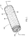
- FIGURE 1 shows a pictorial view of an elongate
cylindrical metal-air cell of the invention.
- FIGURE 2 shows a cross-section of the cell, taken at 2-2
of FIGURE 1.
- FIGURE 3A is an enlarged representative cross-section of
the side wall and bottom wall structures at the bottom of the
cell, including the air cathode, and is taken at dashed circle
3A in FIGURE 2.
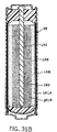
- FIGURE 3B is an enlarged representative cross-section of
the side wall and grommet and other seal structures at and
adjacent the top of the cell, also showing the air cathode,
and is taken at dashed circle 3B in FIGURE 2.
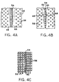
- FIGURE 4 shows a representative cathode current collector
used in air cathode assemblies of the invention.
- FIGURES 4A, 4B, 4C illustrate respectively a continuous-weld
butt joint, a spot weld butt joint, and a joint formed
by welding interdigitated wires or fingers.
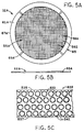
- FIGURE 5 shows a representative perforated metal sheet
useful for making the cathode current collector of FIGURE 4.
- FIGURE 5A shows a representative perforated metal cathode
current collector for use in a button cell, and having a
generally imperforate contact zone.
- FIGURE 5B shows a representative edge view of the cathode
current collector of FIGURE 5A.
- FIGURE 5C shows a metal strip illustrating an array of
patterns of circular etched precursors of cathode current
collectors, from which current collectors of FIGURE 5A can be
made.
- FIGURE 5D shows a representative cross-section of an air
depolarized button cell employing a cathode current collector
of FIGURES 5A and 5B.
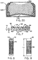
- FIGURE 6 shows an enlarged portion of a corner of the
metal sheet of FIGURE 5, illustrating hexagonal perforations.
- FIGURE 7 is an enlarged representative cross-section of
the air cathode illustrated in FIGURE 3A.
- FIGURE 8 is a representative pictorial view of an
elongate cylindrical cathode current collector having circular
perforations.
- FIGURE 9 is a representative pictorial view of an
elongate cylindrical cathode current collector having square
perforations.
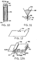
- FIGURE 10 is a representative pictorial view of a
cylindrical cathode current collector of the invention, and
active carbon catalyst secured to the current collector.
- FIGURE 11 is a representative elevation view of apparatus
for forming a sheet of the active carbon catalyst.
- FIGURES 12 and 12A are representative pictorial views,
with parts cut away, of an active carbon sheet, and a stack
of such sheets being formed into a cross-bonded composite of
such sheets.
- FIGURE 13 is a representative pictorial view of the
assembled air cathode, including cathode current collector,
active carbon catalyst, and diffusion member.
- FIGURE 14 is a representative pictorial view of a stack
of pressure rolls used for assembling the active carbon
catalyst, and the diffusion member, to the cathode current
collector.
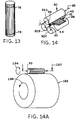
- FIGURE 14A is a representative orthogonal view
illustrating alternative apparatus and methods for assembling
the active carbon catalyst, and the diffusion member, to the
cathode current collector.
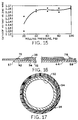
- FIGURE 15 is a graph illustrating the effect of rolling
pressure on cathode voltage.
- FIGURE 16 is an enlarged longitudinal cross-section, with
parts cut away, of an air cathode useful in assembling an
elongate cell of the invention.
- FIGURE 17 is an enlarged transverse cross-section, with
parts cut away, of an air cathode useful in assembling an
elongate cell of the invention.
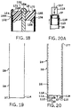
- FIGURE 18 is a cross-section of a top portion of a cell
of the invention illustrating a stop groove in the cathode
can.
- FIGURE 19 is a representative cross-section of a drawn,
or drawn and ironed, pre-form used to make cathode cans for
use in cells of the invention.
- FIGURE 20 is a representative cross-section of a second
stage pre-form, made from the pre-form of FIGURE 19.
- FIGURE 20A illustrates the process of converting the pre-form
of FIGURE 19 to the cross-section configuration shown in
FIGURE 20.
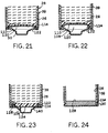
- FIGURES 21-24 and 28 are representative cross-sections
of bottom portions of cathode cans made using pre-forms of
FIGURES 19 and 20.
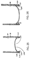
- FIGURE 25 is a representative cross-section of a second
embodiment of a second stage pre-form, made from the pre-form
of FIGURE 19.
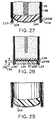
- FIGURES 26-27 are representative cross-sections of bottom
portions of cathode cans made using pre-forms of FIGURE 25.
- FIGURE 28 is a representative cross-section showing a
wide seal bead being formed at the bottom flange of the
cathode can.
- FIGURE 29 is a photograph showing a cross-section of the
bottom portion of a partially assembled cell, configured as
the bottom portion of the cell in FIGURE 26, and made using
in situ melting as the method of placing the bottom seal.
- FIGURE 30 is a representative cross-section of a cell of
the invention similar to the cell of FIGURE 2, and
illustrating an alternate top seal structure.
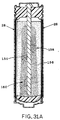
- FIGURE 31A is a representation of a photograph showing
a cross-section of a portion of a cell which has undergone
significant discharge, wherein the zinc was loaded into the
anode cavity in generally dry condition, and illustrating
progression of the reaction front from the cathode current
collector toward the anode current collector.
- FIGURE 31B is a representation of a photograph showing
a cross-section of a portion of a cell which has undergone
significant discharge, wherein the zinc was loaded into the
anode in a wet or gelled condition, and illustrating
progression of the reaction front from the cathode current
collector toward the anode current collector.
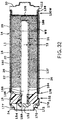
- FIGURE 32 is a cross-section of a cell of the invention
as in FIGURE 2, and employing a hollow tubular anode current
collector as a mass-control chamber.
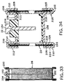
- FIGURE 33 is a cross-section of a can-less embodiment of
a cell of the invention.
- FIGURE 34 is a fragmentary cross-section showing top and
bottom portions of the cell of FIGURE 33, further enlarged.
- FIGURES 34A-34D illustrate cross-sections of additional
embodiments of top closure structure of the cell.
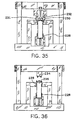
- FIGURES 35 and 36 show representative elevation views of
apparatus useful for closing and crimping the top and bottom
members of can-less embodiments of cells of the invention.
- FIGURE 37 shows a cross-section of a can-less embodiment
of cells of the invention, utilizing a hollow anode current
collector.
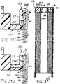
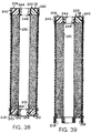
- FIGURE 38 shows a cross-section of a can-less embodiment
of cells of the invention, utilizing a hollow anode current
collector, having central openings in both the top and the
bottom of the cell.
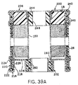
- FIGURE 39 illustrates a cross-section as in FIGURE 38,
and utilizing a modified bottom structure of the cell.
- FIGURE 39A is a fragmentary cross-section showing top and
bottom portions of the cell of FIGURE 39, further enlarged.
-
-
The invention is not limited in its application to the
details of construction or the arrangement of the components
set forth in the following description or illustrated in the
drawings. The invention is capable of other embodiments or
of being practiced or carried out in various ways. Also, it
is to be understood that the terminology and phraseology
employed herein is for purpose of description and illustration
and should not be regarded as limiting. Like reference
numerals are used to indicate like components.
DESCRIPTION OF THE ILLUSTRATED EMBODIMENTS
-
An elongate cylindrical metal-air cell 10 is shown in
pictorial view in FIGURE 1. A longitudinal cross-section of
the cell of FIGURE 1 is shown in FIGURE 2. An enlarged
portion of the cross-section of the cell of FIGURE 2, at the
bottom of the cell, is shown in FIGURE 3A. An enlarged
portion of the cross-section of the cell of FIGURE 2, at the
top of the cell, is shown in FIGURE 3B.
-
The structure of cell 10 represents the result of
applicant drawing on a combination of technologies including
from, among other places, (i) 2-electrode cylindrical bobbin
cell technology (e.g. zinc-manganese dioxide round cells), and
(ii) zinc-air hearing aid cell technology (zinc-air button
cells), and making novel combinations using such information,
in addition to elements novel in and of themselves, in
arriving at cell 10 as illustrated, as well as other
embodiments of the invention.
-
As with zinc-air button cells, the active air cathode
assembly in an elongate cell of the invention is quite thin,
allowing for a large fraction of the cell volume to
potentially be occupied by zinc anode material, thus providing
for disposition of anode material in close proximity with the
air cathode assembly adjacent the outer cylindrical sides of
the elongate cell, as well as allowing for increased weight
of anode material in the elongate cell. Greater anode weight
potentially enables the cell to deliver about two to three
times the discharge watt-hours of a standard 2-electrode
alkaline zinc-manganese dioxide cell of the same size and
configuration.
-
The dominant electrochemical reactions associated with
operation of zinc-air cells, in general, are generally
considered to be as follows.
Similar reaction mechanisms can be derived for electroactive
reactions of other air depolarized cells.
-
However, whereas in air depolarized button cells the air
cathode is a generally planar element of the cell along the
bottom wall of the cell, air cathodes in elongate air
depolarized cells of the invention are disposed along the
elongate, generally arcuate, side walls of the cells, whereby
typical such air cathodes are correspondingly arcuate in
shape. While typical elongate cells of the invention are
cylindrical, and thus have circular cross-sections, in the
alternative, elongate cells of the invention need not be
cylindrical. Rather, such cells can have a variety of cross-sectional
shapes, including any closed-perimeter cross-section.
The cross-section can thus be ovoid, square,
rectangular, or any other polygonal cross-section, arcuate
cross-section, or combination of straight-line and arcuate
cross-section. It is preferred, however, that the cross-section
define a perimeter devoid of acute interior angles,
such that the thickness of electroactive anode material
between the cathode assembly and the anode current collector
is relatively uniform about the perimeter of the cell.
-
Still referring to FIGURES 1, 2, 3A, and 3B, cell 10 has
an anode 12, a cathode 14, a separator 16, and a grommet 18.
In general, anode 12 includes anode mix 20, anode current
collector 22, and an optional anode cap 24. Cathode 14
includes a cylindrical air cathode assembly 26, a cathode can
28, and an optional cathode cap 30. Cylindrical air cathode
assembly 26 includes a cathode current collector 32, an active
carbon catalyst 34, and an air diffusion member 36. Cathode
can 28 has a bottom wall 37 and a side wall 39. A
multiplicity of air ports 38, extend through, and are
generally evenly distributed about, side wall 39, for entry
of air, and thus cathodic oxygen, into the cell at the
cathode.
-
Separator 16 serves as a barrier to flow of electricity
between anode 12 and cathode 14, while accommodating flow of
electrolyte between the anode and the cathode.
-
Grommet 18 assists in blocking flow of electrolyte and
electroactive anode material past the top edge of air cathode
assembly 26, and out the top of the cell. Further, grommet
18 electrically insulates anode mix 20 from cathode current
collector 32. Still further, grommet 18 separates, and
electrically insulates, anode current collector 22 from the
cathode, especially cathode can 28.
-
Separator 16 and grommet 18 thus, in combination, prevent
internal shorting of the cell; namely prevent direct flow of
electricity between the anode and cathode internally
(shorting) in the cell without the application of such
electricity to a circuit outside the cell.
-
Both the anode and the cathode are impregnated with
suitable alkaline electrolyte based on, for example, aqueous
potassium hydroxide liquid.
THE CATHODE
-
Cathode 14 includes cylindrical air cathode assembly 26,
cathode can 28, and optional cathode cap 30. Cylindrical air
cathode assembly 26 includes cathode current collector 32,
active carbon catalyst 34, and air diffusion member 36.
Cathode can 28 includes bottom wall 37, side wall 39, and air
ports 38 (FIGURE 3A) through side wall 39, for entry of air,
and thus cathodic oxygen, into the cell.
THE AIR CATHODE ASSEMBLY
-
Air cathode assembly 26 is structured with active carbon
catalyst 34 generally interposed between current collector 32
and air diffusion member 36. In the cylindrical environment,
in the preferred embodiments, the cathode current collector
and the active carbon catalyst, in combination, generally form
the inside surface of the cathode assembly, and the air
diffusion member generally forms the outside surface of the
cathode assembly. The invention does contemplate embodiments
wherein active carbon catalyst fully encloses the inside
surface of the cathode current collector opposite the reaction
surface area such that the inside surface of the cathode
assembly is defined generally overall by an inner surface of
the active carbon catalyst.
THE CATHODE CURRENT COLLECTOR
-
As illustrated in FIGURE 4, cathode current collector 32
has a cylindrical configuration and collects and transports
electric current at and through, to and from, the cathode.
The cathode current collector generally provides that
structural material which contributes most to defining the
overall length, and the inner diameter, of the air cathode.
In the embodiment illustrated in FIGURE 4, the current
collector further provides substantially all the structural
hoop strength present in the air cathode.
-
A preferred embodiment of cathode current collector 32
for use in an elongate cylindrical cell is illustrated in
FIGURE 4 and is generally made from a square or otherwise
rectangular, perforated metal sheet 40, illustrated in FIGURE
5. Metal sheet 40 has top and bottom edge portions 42, 44,
respectively, and right and left edge portions 46, 48,
respectively. As illustrated in FIGURES 4 and 5, top and
bottom edge portions 42, 44, and right and left edge portions
46, 48, are preferably not perforated like the remainder of
sheet 40.
-
While top and bottom edge portions 42, 44, and right and
left edge portions 46, 48, can have some perforations in some
embodiments, the high level of perforations extant over the
remaining majority of sheet 40 is not preferred in especially
right and left edge portions 46, 48.
-
For a "AA" size elongate cell, top and bottom edge
portions 42, 44 typically have widths "W1" of about 0.1 inch.
See FIGURE 6. As discussed hereinafter, bottom edge portion
44 provides a smooth surface for facilitating electrical
contact between current collector 32 and the cathode can. Top
edge portion 42 provides a smooth surface for assisting in
creating a seal against leakage of liquid electrolyte past the
cathode assembly and grommet 18.
-
Current collector 32 can be fabricated from a metal sheet
as illustrated in FIGURE 5 into a cylindrical configuration
such as that shown in FIGURE 4 by, for example, welding, such
as laser butt welding (FIGURES 4A, 4B), respective left and
right distal edges 50, 52 of edge portions 46, 48 to each
other to create a joint 54 along the length of the
cylindrically configured sheet 40, thereby to fixedly secure
the cylindrical configuration.
-
While joint 54 can be formed by e.g. welding overlapped
elements of the structure of edge portions 46, 48, the
resulting double thickness of sheet material 40 at the
resulting joint 54 is not preferred. Accordingly, joint 54
is preferably fabricated without layer-on-layer overlapping
of the structures of edge portions 46, 48 one on the other.
Rather, distal edges 50, 52 are preferably butted against each
other in fabrication of the butt welded embodiments shown in
e.g. FIGURES 4A, 4B.
-
The illustrated e.g. butt welding thus creates
longitudinal joint 54, which can be a series of spot welds
(FIGURE 4B), or can be a continuous weld (FIGURE 4A). Any
other operable method of joining edges 50, 52 which thereby
effectively converts metal sheet 40 into the cylindrical, or
otherwise closed, configuration seen in FIGURE 4, is
acceptable. The recited exemplary and preferred laser butt
welding of metal sheet 40 can be done by Laser Services, Inc.,
Westford, Massachusetts, USA.
-
Right and left edge portions 46, 48 typically have widths
"W2" of about 0.03 inch, to provide desirable quantities of
material from which butt weld 54 can be formed.
-
Metal sheet 40 includes perforations 56 (FIGURES 5, 6,
7) extending through the thickness "T1" (FIGURE 7) of metal
sheet 40, from outer surface 58 to inner surface 60. A
typical such metal sheet, suitable for fabricating cylindrical
current collector 32 for a "AA" size elongate cell, contains
about 4000 of such perforations 56 as illustrated by Table 1.
The number of perforations depends on the sizes and
configurations of the perforations, and the widths "W3" of
webs 62 between the respective perforations. Perforations 56
are preferably regular hexagons, measuring about .02 inch
between opposing straight sides thereof. In the embodiments
illustrated in FIGURES 4, 5, and 6, the widths "W3" of webs
62 are preferably also about 0.02 inch. Accordingly, in the
embodiments illustrated in FIGURES 4, 5, and 6, perforations
56 represent about 65% of the overall surface area of metal
sheet 40. In general, for a cell intended for use to deliver
a high rate of electrical discharge, perforations 56 should
usually represent about 45% to about 70% of the overall
surface area of that portion of metal sheet 40 which is
perforated.
-
While perforations 56 have been illustrated as regular
hexagons, a variety of other shapes are acceptable. There can
be mentioned, for example, circles, squares, and e.g.
equilateral triangles. Circular perforations 56 are
illustrated in current collector 32 shown in FIGURE 8. Square
perforations 56 are illustrated in current collector 32 shown
in FIGURE 9. However, because of advantageous resulting
strength of the so-fabricated cathode current collector, and
effective securement of the active cathode catalyst to current
collectors having hexagonal perforation, regular hexagonal
perforations 56, as illustrated in FIGURES 5 and 6, are
preferred. After hexagons, the other shapes which create
corners are preferred because the corners improve securement
of the active cathode catalyst to the current collector, as
compared to, for example, circles, ellipses, and like shapes
which are devoid of corner structure where two side edges of
the corresponding opening come together.
-
Table 1 illustrates typical parameters of various
perforations such as those shown in FIGURES 5 and 6 for a
cathode current collector sized for a "AA" size elongate cell.
The column labeled "Open %" refers to that portion of the
metal sheet which is perforated, irrespective of
edge portions
42, 44, 46, 48.
-
In general, the reaction sites where the cathode half
reaction takes place are believed to be located toward the
outer surface 63 of active carbon catalyst 34. Since
electrolyte flows through perforations 56 to reach the
reaction sites, the fraction of the projected cross-section
of current collector 32 which is represented by the
perforations 56 has an influence on the reaction rate. The
greater the fraction of the surface area of current collector
32 represented by the perforations, the greater the potential
capacity of the cathode assembly for movement of electrolyte
through the perforations; and thus the greater the potential
reaction rate.
-
Where a lesser fraction of the surface area of the
current collector is represented by the perforations, the
potential reaction rate is correspondingly less. Thus,
assuming that other parameters are not otherwise controlling,
the projected area of the perforations can positively, or
negatively, affect the reaction rate. Where the perforations
represent a significant limiting factor in the reaction rate,
the open fraction of the current collector surface area thus
represents the ability to design the current collector as the
control mechanism for determining the overall limiting
reaction rate of the cell, and thus the limiting current of
the cell. Accordingly, where it is desired to increase, or
decrease, the limiting current of the cell, the number and/or
sizes of perforations 56 can be specified accordingly.
-
Where the sizes of perforations 56 are desirably
reduced, but limiting current is to be maintained or
increased, the number of perforations is accordingly
increased. Thus, the number and sizes of perforations 56
depends in general on the performance parameters desired for
cell 10, in combination with the physical strength required
of the current collector. The inventors thus contemplate a
wide range of sizes for perforations 56, and a wide range of
numbers of perforations, for a given cell size, which can be
used for cathode current collectors 32 of the invention.
Accordingly, in a size "AA" elongate cell, the number of
perforations 56 can be as low as about 200 where a high rate
of electromotive force production is not necessary.
-
If cathode current collector 32 has less than about 200
perforations, and maintains the perforations having the
suggested range of fractions of the overall surface area of
the current collector, the physical strength of the current
collector and/or securement of the active carbon catalyst to
the current collector may be compromised.
-
In general, increasing the number of perforations does
not appear to have any negative affect on cell performance.
However, as the number of perforations is increased over a
given metal sheet surface area, the sizes of the perforations
necessarily decrease. Further, as the target size of the
perforation is reduced, the ability to fabricate perforations
to precisely uniform and controllable sizes, configurations,
and spacing, decreases unless additional fabrication controls
are employed.
-
Whatever the target number of perforations and the
target size of the perforations, it is preferred that all
perforations on a given current collector be generally the
same size, and that the perforations be generally uniformly
distributed over the perforated region 55 of the current
collector. The perforated region 55 is that portion
bounded by the imperforate top, bottom, left, and right
portions, as appropriate. "Imperforate" border regions
include any border region or portion of a border region which
is perforated to an extent significantly less than the extent
of perforation of the central region, whereas "truly
imperforate" refers to e.g. border regions which are fully
without perforations. It is within the scope of the invention
that any one current collector have any one, any combination,
or all, of perforated borders, imperforate borders, and truly
imperforate borders.
-
In particular, the smaller the target size for the
perforations, the greater the difficulty, and cost, of
repeatedly making the perforations to specific size,
configuration, spacing, and/or location. Thus, as the target
size of the perforations is reduced, one either sacrifices
precision and repeatability of size, configuration, spacing,
and/or location of the perforations, or tolerates increased
cost. However, where suitable manufacturing controls are in
place for fabricating perforations 56, and the cost can be
tolerated, the number of such perforations in a cathode
current collector sized for a "AA" size elongate cell, can be
any number up to and including 10,000 perforations, or more.
However, for a "AA" size cell, the number of perforations is
preferred to be about 500 to about 6000 perforations, with a
normal average number of perforations being about 4000
perforations.
-
Accordingly, the actual number of perforations used in
a particular implementation of the invention results from
balancing the benefit, if any, in the particular use for which
the cells are planned, of a larger number of smaller
perforations against the cost of making such larger number of
smaller perforations.
-
The acceptable range of the number and sizes of
perforations, of course, depends on the size of the overall
surface area of metal sheet 40 being perforated. Thus, where
a larger cell is being fabricated, and a respectively larger
overall surface area of metal sheet is being perforated as the
current collector, the upper end of the range of the
acceptable number of perforations is increased accordingly.
Where a smaller cell is being fabricated, and a respectively
smaller overall area is being perforated as the current
collector, the lower end of the range of the acceptable number
of perforations is reduced accordingly.
-
In the preferred embodiment, perforations 56 as in
FIGURES 5 and 6 are preferably fabricated by placing a
suitable photo mask on metal sheet 40. The unmasked areas of
the sheet are then acid etched to thereby fabricate the
perforations.
-
In an alternate construction, current collector 32 can
be made of woven wires rather than a perforated metal sheet.
Preferred screen size corresponds to greater size wire and
openings than 200 standard mesh size. Mesh sizes of about 16
to about 100 tend to work well. Mesh sizes 24, 37, and 40
work particularly well. Similar sizes for perforations 56 and
webs 62 are contemplated in the embodiments made with etched
metal sheet.
-
In some embodiments, metal sheet 40 is perforated right
up to and including right and left distal edges 50, 52, while
edge portions 42, 44 are retained imperforate, whereby edge
portions 46, 48 are obviated. Further, woven wire embodiments
may not include imperforate edge portions 46, 48. In such
embodiments, butt welding of distal edges 50, 52 to create
joint 54 is somewhat more difficult because of the void spaces
between webs 62 at distal edges 50, 52, or between adjacent
wires in woven wire embodiments. In place of butt welding,
cooperating webs 62, or corresponding wires 62, can be
interdigitated, and edges of such interdigitated webs or wires
can be welded together as a third example of methods of
forming joint 54. Given the greater precision required for
joinder of edges 50, 52, where perforations 56 extend to edges
50, 52, fabrication considerations suggest that such
embodiments are not preferred.
-
In still other embodiments, metal sheet is perforated
right up to top and bottom distal edges 57, 59, while edge
portions 46, 48 are or are not retained imperforate, whereby
edge portions 42, 44 are obviated. In such embodiments, use
of the upper edge area of cathode current collector 32 in
forming a seal against electrolyte leakage may be somewhat
degraded such that there may be a need to employ other
provisions for leakage control. Similarly, use of the lower
edge area of the cathode current collector as a contact
surface for making electrical contact with the cathode can may
be somewhat less robust than imperforate embodiments, such
that other provisions for electrical contact may be employed.
However, such spaced contacts between the cathode current
collector and the cathode can or other cathode terminal is
routinely used with satisfactory result, in air depolarized
button cells. Nonetheless, considerations of performance
potential suggest that perforations up to top and bottom
distal edges 57, 59 are not preferred.
-
Metal sheet 40 can be made from any material which
provides suitable conductivity for collecting and transmitting
the electrical current flowing through the cathode, while
tolerating the alkaline electrolyte environment. Typical
material for metal sheet 40 for embodiments illustrated in
FIGURES 1, 2, 3A, 3B, 4, 5, 6, and 7, for a size "AA" elongate
cell, is nickel sheet .005 inch thick. The range of
thicknesses of the cathode current collector for a size "AA"
cell is from about .003 inch to about .010 inch. Thinner
materials outside the recited range may be difficult to
fabricate, and may lack sufficient structural strength.
Thicker materials may be too rigid to fabricate into annular
shape. In addition, such thicker materials do use greater
amounts of raw materials, and do occupy a greater fraction of
the limited space available inside the cell.
-
The full complement of sizes within the recited range
can be utilized in the invention, for example and without
limitation, .004 inch, .006 inch, .007 inch, or .008 inch.
Thinner material is preferred where emphasis is placed on
minimizing the thickness of non-reactive materials, thus to
provide greater internal volume inside the cell for packing
in a greater quantity of electroactive anode material or thus
to control weight of the cell. Thicker material is preferred
where emphasis is placed on physical strength and/or rigidity
of the air cathode assembly.
-
Hoop strength of annular current collector 32 as in
FIGURE 4 is related to the mathematical square of the
thickness of sheet metal 40. Thus, the strength of a current
collector .007 inch thick has approximately two times the hoop
strength (7 X 7 = 49) of a corresponding current collector
which is .005 inch thick (5 X 5 = 25). Overall, the ratio of
the strength of the .007 inch thick current collector to the
strength of the .005 inch thick current collector is thus
49/25 = 1.96/1.
-
In other embodiments, metal sheet 40 is replaced with
e.g. cross-bonded woven wire of a size similar to metal sheet
40. In such structure, the wires generally take the place of
webs 62. The diameter of such woven wire is generally about
.003 inch to about .010 inch thick and includes the full
complement of sizes within the recited range, as recited
herein for the sheet metal thickness. Current collectors can
be fabricated from such wire by butt welding, as in FIGURE 4,
adjoining surfaces of respective cooperating wires in the
weave. In place of butt welding, cooperating wires can be
interdigitated as discussed herein above, and cooperating
edges of such interdigitated wires welded together, as shown
in FIGURE 4C. The bottom edge of FIGURE 4C illustrates
perforations 56 extending to the distal edge 59 of the bottom
of the current collector. FIGURE 4C further illustrates the
wires (e.g. 62) interdigitated at the lower portion of the
FIGURE, and the interdigitated wires welded to each other to
form joint 54 at the upper portion of the FIGURE.
-
Still another embodiment of the cathode current
collector is represented by an article woven or otherwise
fabricated as a seamless annulus, e.g. cylinder. Where a
seamless annulus is woven, top and bottom edge portions 42,
44, and right and left edge regions 46, 48, are obviated,
although imperforate edge portion elements representative of
imperforate edge portions 42, 44 can be secured to the woven
article as by welding at or adjacent upper and lower distal
edges of the seamless annular current collector.
-
Regarding other materials which can be used in place of
the nickel sheet, there can be mentioned nickel plated steel,
nickel plated stainless steel such as 305 stainless steel,
nickel plated iron, and like materials, either alone or as
composite compositions or platings, such other like materials
being, for example, noble metals such as gold, silver,
platinum, palladium, iridium, rhodium, and the like, which can
tolerate the alkaline environment inside the cell without
excessive local e.g. gas generating reactions. Where a
plating is used, the substrate is preferably plated after
perforations 56 are fabricated.
-
FIGURES 5A, 5B, 5C, and 5D represent a further
implementation of the concept of providing a cathode current
collector 32A in an air depolarized cell 510, wherein the
cathode current collector has an imperforate border region
61A, the outer edge 67A of imperforate border region 61A being
an elongate electrical contact surface providing electrical
contact, directly or indirectly, with cathode can 528 or other
cathode conductor or terminal. In the embodiments represented
by FIGURES 5A, 5B, 5C, and 5D, current collector 32A
represents a flat sheet configuration such as the flat disc-like
configuration used for cathode current collectors in
commercially available air depolarized button cells.
-
As seen in FIGURE 5A, current collector 32A has a
generally perforated central region 55A, and an imperforate
border region 61A extending entirely about and thus generally
encompassing or surrounding the central region. While any of
the above illustrated or suggested configurations can be
employed for the perforations, perforations 56A further
illustrate perforations having square configurations.
-
Optional slots 65A extend inwardly from outer edge 67A
of border region 61A, generally toward the central region, and
may extend the full distance to the central region. Slots 65A
provide structure effective to enhance predictability,
repeatability, and thus overall control of doming of the
cathode assembly, the doming being illustrated at 529 in
FIGURE 5D, in an air depolarized button cell. Namely, the
number, and the shapes, such as depths and widths, of slots
65 are related to the degree of doming of the air cathode
assembly.
-
A wide range of shapes are contemplated for slots 65A,
including without limitation the illustrated rectangles, as
well as squares, circles, semi-circles, triangles, slits,
dart-shaped openings, irregular openings, and the like. While
the illustrated rectangular slot openings extend generally
perpendicular to outer edges 67A, other angles and opening
shapes can be used so long as the respective openings extend
generally toward central region 55A. Accordingly, in general,
and with allowance for variations according to the shapes of
slots 65A, the greater the fraction of the surface area which
is defined by width "W5" and which is also occupied by slots
65A, the greater is the control over doming.
-
The invention contemplates a variety of widths "W5" of
border region 61A. Where a seal or grommet 518 is used
between an anode can 531 and cathode can 528 in a button cell,
as illustrated generally in FIGURE 5D, such seal or grommet
overlies an outer peripheral portion of the air cathode
assembly, thereby blocking off that outer peripheral portion
of the air cathode assembly from access to anode material at
the separator. Such blocking off of the outer peripheral
portion of the air cathode assembly significantly reduces
usefulness of that outer peripheral portion in the cathode
half reaction, such that the remaining inner portion of the
air cathode assembly, namely that portion inwardly of and not
blocked off by, the seal or grommet, is sometimes referred to
as the reaction surface area or similar nomenclature.
-
Returning again to FIGURE 5A, the width "W5" of border
region 61A can generally correspond with the entire outer
peripheral portion of the air cathode assembly, which will
face the seal or grommet, without negatively affecting or
otherwise controlling the useful size of the reaction surface
area of the air cathode assembly. And the wider the border
region, the more effective is the border region in assisting
in controlling doming of the cathode assembly, and in
assisting in controlling leakage of electrolyte around the
outer edge of the cathode assembly, as well as providing
improved electrical contact with the cathode can, as compared
to a current collector wherein the border region and central
region are similarly perforated.
-
While current collector 32A is preferably configured as
a single sheet having suitable perforations, slots, etc., a
variety of other structures and configurations are
contemplated, along with corresponding methods of fabricating
such other structures and configurations. For example, the
current collector can be made from an imperforate band
affixed, as by welding, to a woven wire central region.
-
In current collector 32A, e.g. sheet material structure
used in central region 55A, wire structure used in central
region 55A, or sheet or wire used in border region 61A, can
have thicknesses of about .003 inch to about .010 inch, with
thicknesses of about .004 to about .008 inch being preferred.
Most preferred material thicknesses are about .005 inch to
about .007 inch, including about .006 inch.
-
The range of materials which can be used to fabricate
current collector 32A includes the same compositions, and the
same structures, as are recited above for current collector
32. Any known method for making perforations in metal sheet
can be used to make perforations 56A, including the use of
woven wire to fabricate the perforated central region, or the
above noted combination of photo mask and acid etching of
metal sheet. Thus, "perforated," "imperforate," and like
expressions include, without limitation, both perforated metal
sheet material, woven wire articles, and articles made of
woven web material. Web material is an elongate wire-like or
strap-like structure having width greater than top-to-bottom
thickness.
-
Perforations 56A, and the corresponding webs, can have
any of the shapes and configurations described above for
perforations 56 such as square, circular, hexagonal, and the
like.
-
FIGURE 5C illustrates generally a process for
fabricating current collectors 32A. As suggested in FIGURE
5C, cooperating registration holes 533 are fabricated along
opposing edges 535, 537 of a suitable metal strip 539 having
thickness and composition consistent with the above recited
thicknesses and compositions. Suitable photo mask and acid
etching are then employed, in cooperation with registration
holes 533, thereby to fabricate multiple spaced circular
arrays 541 of perforations 56A representing respective central
portions 55A of precursors of current collectors 32A. The
respective arrays 541 are subsequently punched from metal
strip 539, along with a corresponding border region about each
array, to thus fabricate a corresponding number of cathode
current collectors 32A. As an array is punched out of strip
539, the correspondingly punched border region becomes region
61A in the respective current collector 32A.
-
An advantage of the border region 61A, as compared to
a current collector made entirely of woven wire or the like,
is that the entire outer edge 67A of the border region is
available for making electrical contact with the cathode can
whereas only ends of the respective wires are so available in
a current collector made entirely from wire, for making
electrical contact with the cathode can. In addition, the
border region participates in the formation of an effective
seal against leakage of electrolyte out past the grommet and
thence out of the cell.
THE ACTIVE CARBON CATALYST
-
Active carbon catalyst 34 is generally supported on
current collector 32. The active carbon catalyst provides
reaction sites where oxygen from the air reacts with water
from the electrolyte, e.g. according to the above cathode half
reaction, to generate the hydroxyl ions which are later used
in the anode to release electrons, e.g. according to the anode
half reaction. Carbon particles in the active carbon catalyst
thus provide solid reaction sites for the air/liquid interface
where aqueous liquid and gaseous oxygen come together and
effect the electroactive cathode half reaction.
-
The carbon catalyst cooperates with the current collector
in collecting and/or conducting current within the cathode in
support of the cathode half reaction.
-
In order to limit internal resistance in the cathode,
during the process of joining carbon catalyst to the current
collector, the carbon catalyst is brought into intimate
contact with current collector 32, including and especially
at perforations 56. Referring to FIGURES 3A, 7 and 10, carbon
catalyst 34 preferably extends through perforations 56 and
extends outwardly of the projections of perforations 56 at and
adjacent inner surface 60 of current collector 32. Thus, the
carbon catalyst is generally intimately interlocked with
current collector 32, through perforations 56, about the
perimeter edges of the respective perforations, at both outer
and inner surfaces 58, 60 of the current collector.
-
Referring to FIGURE 10, upon completion of assembly of
the carbon catalyst to the cathode current collector, carbon
catalyst 34 preferably covers the entirety of that portion of
cylindrical outer surface 58 of the current collector which
lies between top edge portion 42 and bottom edge portion 44.
-
Carbon catalyst 34 is a combination of carbon particles,
a binder, and processed potassium permanganate. During
processing of the potassium permanganate in creating carbon
catalyst 34, the carbon reduces the manganese to valence state
+2 (hereinafter "manganese (II)"). The combination of valence
state +2 manganese, with suitably activated carbon, acts
successfully as catalyst for reduction of oxygen in air
cathodes. As a result of in situ reactions, catalytically
active manganese (II) forms in the matrix of the active carbon
catalyst.
-
Carbon catalyst 34 can be fabricated, and mounted on
current collector 32 as follows. The carbon used in
fabricating catalyst 34 is represented by carbon particles
having surface area greater than 50 square meters per gram
(m2/g), preferably greater than 150 m2/g, more preferably
greater than 250 m2/g, still more preferably between about 250
m2/g and 1500 m2/g, yet more preferably between about 700 m2/g
and 1400 m2/g, further more preferably between about 900 m2/g
and 1300 m2/g, and most preferably between about 1000 m2/g and
1150 m2/g.
-
In a preferred embodiment, carbon of the present
invention has the following characteristics; surface area
between 1000 m2/g and 1150 m2/g, apparent density of about
0.47 g/cc to about 0.55 g/cc, preferably about 0.51 g/cc; real
density of about 1.7 g/cc to about 2.5 g/cc, preferably about
2.1 g/cc; pore volume of about 0.80 to about 1.0 g/cc,
preferably about 0.90 g/cc; specific heat at 100 degrees C of
about 0.20 to about 0.30, preferably about 0.25; and about 65%
to 75% of such material will pass through a wet -325 US
Standard mesh screen wherein the nominal opening size is .0017
inch (.045 mm). Such preferred carbon is available as PWA
activated carbon from Activated Carbon Division of Calgon
Corporation, Pittsburgh, PA.
-
Generally, a range of carbon particle sizes is acceptable
for processing of the material required in fabricating the
active carbon catalyst. Particle size can be measured using
a laser light scattering technique such as, for example, that
provided by using a Model 7991 MICROTRAK particle-size
analyzer manufactured by Leeds & Northrup.
-
Typical particle sizes of particles of the preferred PWA
carbon are given numerically in Table 2.
| Particle Size of PWA Activated Carbon Particles |
| Diameter, Microns | Volumetric Percent |
| 125-176 | -0- |
| 88-125 | 11.8 |
| 62-88 | 7.1 |
| 44-62 | 9.7 |
| 31-44 | 17.1 |
| 22-31 | 12.4 |
| 16-22 | 7.4 |
| 11-16 | 7.3 |
| 7.8-11 | 10.0 |
| 5.5-7.8 | 5.1 |
| 3.9-5.5 | 5.6 |
| 2.8-3.9 | 4.1 |
| 0.0-2.8 | 2.0 |
-
As illustrated in TABLE 2, PWA activated carbon particles
have sizes ranging primarily between about 8 microns and about
125 microns, with about 71% by volume being small enough to
pass through the .045 mm opening of a -325 mesh screen, about
65% by volume of the particle sizes being between 16 microns
and 125 microns, about 40% by volume being between 22 microns
and about 62 microns, and a small fraction of about 6% by
volume being less than 4 microns.
-
In the embodiments contemplated for use in this
invention, a degree of physical mechanical integrity is
required of sheets of the active carbon material to enable the
process of joining and securing the active carbon to the
cathode current collector. To that end, polymeric halogenated
hydrocarbon binder, or other suitable binder, is distributed
substantially evenly throughout the mixture of carbon
particles and manganese moiety. While choosing to not be
bound by theory, applicants believe that, in some embodiments,
upon completion of the steps performed in fabricating the
carbon composition into finished sheet form, the halogenated
hydrocarbon binder forms a 3-dimensional web of interlocking
fibers or fibrils of the binder material, thus imparting
desired physical sheet integrity to the active carbon catalyst
composition/mixture.
-
A preferred binder is polytetrafluoroethylene (PTFE).
The optimum amount of PTFE is about 5% by weight of the
finished active carbon catalyst product. Other binders known
to bind carbon particles of the stated size range, in
fabricating electrodes, are acceptable.
-
More or less binder can be used, between about 3% by
weight and about 10% by weight. Where less than about 3%
binder is used, the binding effect may be unacceptably low.
Where greater than 10% binder is used, dielectric or
electrical insulating properties of the binder can result in
less desirable electrical performance of the electrode.
-
The following steps can be used to make the active carbon
catalyst. 1000 milliliters of distilled water is placed in
a non-reactive container. 19 grams of KMnO4 (potassium
permanganate) are added to the container. The mixture of
KMnO4 and water is mixed for ten minutes. 204 grams of PWA
activated carbon having appropriate particle sizes set forth
above are added slowly to the central mix vortex while mixing
is continued. After ten minutes of further mixing, 51 grams
of PTFE (TEFLON T-30 available from DuPont Company,
Wilmington, Delaware) is added slowly, uniformly, and without
interruption to the mix vortex, and mixing is continued for
yet another ten minutes at the speed required to maintain a
vortex in the mix after the PTFE is added, so as to make a
generally homogeneous mixture of the liquid and solid
components and to fibrillate the PTFE.
-
The resulting powder mixture is then separated from the
water by e.g. filtration through Whatman #1 or equivalent
filter paper, and heated in an oven at about 100 degrees C.
to about 140 degrees C. for 16 hours or until dry, to obtain
a dry cake of the carbon, manganese moiety, and PTFE.
-
3 grams of Black Pearls 2000 carbon black, and optionally
5 grams of pre-densified cathode mix from previous
manufacturing runs, are placed in a Model W10-B Littleford
Lodige High Intensity Mixer along with the above-obtained dry
cake of carbon, manganese moiety, and PTFE. The mixture is
mixed at 2600 rpm at ambient temperature for 30 minutes, or
until any and all agglomerates in the mixture are broken down,
and the mixture becomes free flowing, thereby to make a free-flowing
powder mixture 64.
-
The resulting free flowing powder mixture 64 is rolled
into web form in a manner generally illustrated in FIGURE 11.
Referring to FIGURE 11, carbon powder mixture 64 is placed in
a hopper 66 and fed downwardly through the hopper to a
discharge opening such as slot 68, which feeds the powder
mixture to a first nip formed by a pair of polished steel
rolls 70 at suitable speed to position a sufficient amount of
the carbon powder mixture above the nip formed between the
rolls, with which to form a generally continuous web of such
powder mixture. Rolls 70 are driven in cooperating directions
illustrated by arrows 72, at constant common speeds, thus to
draw the powder into the nip between the rolls. The spacing
between rolls 70 is set at a fixed distance sufficient to draw
the carbon powder mixture into the nip and, by the pressure
exerted on the carbon powder mixture as the mixture passes
through the nip, to fabricate the carbon powder mixture into
a web 74, having a thickness of about 0.004 to about 0.010
inch, preferably about .004 inch to about .006 inch, and a
with machine direction (MD) and a cross machine direction
(CD). The constant speed of rolls 70 produces a web 74 having
a relatively uniform thickness along the length of the web.
-
While the web fabricated at rolls 70 can thus be
consolidated from powder form to a single web body, the web
so fabricated is quite fragile.
-
After the web is consolidated as illustrated in FIGURE
11, the web may be wound up as a roll (not shown) or otherwise
consolidated or packaged for storage and/or shipment. In some
embodiments, web 74 is cut cross-wise (along the CD direction)
to thereby produce individual, e.g. generally rectangular
sheets 80, illustrated in FIGURE 12. In such embodiments, 2
to about 6 such individual sheets 80 are stacked on top of
each other with the machine direction (MD) in sequential
sheets in the stack being oriented transverse, preferably
perpendicular, to each other. FIGURE 12A shows such a stack
82 of 4 sheets 80A, 80B, 80C, 80D. Arrows 84 indicate the MD
in each sheet, illustrating the sheets being oriented
perpendicular to each other. A stack of 4 such sheets, each
having a thickness of about 0.005 inch, has a combined
thickness of nominally about .020 inch.
-
With sheets 80 so stacked and arranged, the 4-sheet stack
is passed through a second nip illustrated by rolls 86. Rolls
86 are shown spaced apart for illustration purposes in FIGURE
12A. The spacing at the nip between rolls 86 is set and held
at a uniform nip gap significantly smaller than the sum of the
thicknesses of the sheets in the stack.
-
The size of the spacing between rolls 86 at the gap
should be less than 75% of the combined thicknesses of the
sheets making up the stack. Preferred size of the spacing is
from about 20% up to about 60% of the combined free
thicknesses of the sheets making up the stack, with a more
preferred range of about 25% to about 40% of the combined
thicknesses.
-
During processing of the stack 82 of sheets, rolls 86
preferably rotate at a generally constant speed in cooperating
directions illustrated by arrows 87, and thereby draw the
stack into the nip, thus working the composite 4-sheet stack.
As stack 82 passes through the nip, the sheets are, in
combination, mechanically worked by rolls 86, with the result
that the worked composite sheet stack 82W is significantly
stronger than the unworked sheets, whether taken alone or in
combination. The composite sheet stack is preferably so
worked in suitable nips, preferably from 2 to about 6 times,
or more, until the worked composite sheet stack is suitably
toughened or otherwise strengthened that the resulting worked
composite sheet stack 82W can be handled by commercial speed
production equipment in fabricating elongate electrochemical
cells of the invention having cathode assemblies having
generally arcuate configurations generally corresponding with
the outer arcuate sides of the respective cells.
-
The overall effect of the working of the stack of sheets
is to reduce the thickness of the stack and to effectively
cross-bond and thereby consolidate the sheets to each other,
such that the directionality of the strength of web 74 (e.g.
the MD/CD ratio of tensile strength) is more evenly
distributed in the MD and CD directions in the thus-consolidated,
unitary worked sheet 82W than in an unworked
sheet of similar thickness. Namely, the ratio of crossing
tensile strengths is closer to "1" in the unitary worked sheet
than in the unworked sheets, whether the unworked sheets are
taken individually or in combination. In addition, applicants
contemplate that the work done in the first and second nips
at rolls 70 and 86 further fibrillates the binder, and
interconnects the associated fibrils, into a three-dimensional
net-like arrangement of interconnected binder fibrils, thus
to assist the binder in its role of binding the carbon and
Mn(II) moieties into the resulting worked sheets 82W, or
otherwise containing or holding the carbon and Mn(II) moieties
in sheet form. As a mechanical act, the contemplated three-dimensional
net-like binder arrangement is believed to receive
and hold the carbon particles in the sheet structure,
primarily by mechanical entrapment.
-
PTFE, as a binder, can also serve as a chemical bonding
agent, bonding carbon particles together to form an
adhesively-defined matrix. While adhesive properties of PTFE
are generally activated by heat, applicants contemplate that
the work energy utilized in the working of the stack of carbon
sheets as at the nip formed by rolls 70 and 86 may be
effective to so heat the compositions of the materials being
rolled as to concomitantly and concurrently activate the
adhesive properties of the PTFE. Applicants thus contemplate
that the binding performance of the PTFE in active carbon
catalyst of the invention may be a combination of mechanical
entrapment and such chemical adhesion.
-
The resulting worked sheet 82W is sufficiently strong, in
all directions, to tolerate commercial processing. The
typical worked sheet has an overall thickness in the range of
about .003 to about .010 inch, preferably about .004 go about
.008 inch, and most preferably about .005 go about .007 inch.
-
The following description applies to assembling a worked
carbon sheet 82W to a cylindrical cathode current collector
32 such as that described in FIGURE 4. A work piece 88
(FIGURE 14) of suitable size is cut, as necessary, from worked
sheet 82W. Work piece 88 has a width sized to cover the full
length of cathode current collector 32, save top and bottom
edge portions 42, 44, as shown in FIGURE 10. Thus, work piece
88 is narrower than cathode current collector 32 is long.
-
Work piece 88 has a length sufficient to wrap about the
entire circumference of cathode current collector 32, and to
provide for a modest overlap between the leading edge of the
wrap and the trailing edge of the wrap.
-
Work piece 88 is assembled to cathode current collector
32 using, for example, a 3-roll stack 90 of assembly rolls
92A, 92B, 92C. The lengths of rolls 92A, 92B, 92C are
generally greater than the lengths of the cathode current
collectors whose assembly, to other elements of the air
cathode assembly, they facilitate. Rolls 92A, 92B, 92C are
aligned with each other as shown in FIGURE 14, and are spaced
from each other whereby the rolls typically, but not
necessarily always, rotate without touching each other.
-
Optionally, and preferably, current collector 32 is first
slipped over an e.g. steel mandrel 93. The mandrel generally
fills the space across the diameter of the current collector.
The current collector, in combination with the mandrel, when
the mandrel is used, is then inserted into the central opening
defined by the stack of rolls 92A, 92B, 92C, as illustrated
in FIGURE 14. Pressure is then applied to the stack of rolls
as illustrated by arrows 95, bringing the rolls together, and
against cathode current collector 32. Rolls 92B, 92C, are
preferably fixedly mounted to a support such that rolls 92B,
92C resist the pressure applied by roll 92A through mandrel
93 and current collector 32. Accordingly, the force applied
by roll 92A is effectively applied to current collector 32 and
mandrel 93. Thus, the pressure on the rolls causes the rolls
to apply pressure to outer surface 58 of the current
collector.
-
With pressure thus being applied to the outer surface of
the cathode current collector in the midst of the 3-roll
stack, workpiece 88 of the worked carbon sheet is directed
into a third nip defined between the current collector and top
roll 92A, centered between top and bottom edge portions 42,
44 of the current collector. E.g. top roll 92A is then driven
in the direction indicated by arrow 94. Drives of bottom
rolls 92B, 92C are connected to the drive of top roll 92A
through suitable gearing or other apparatus, not shown, which
causes the bottom rolls to rotate in unison at constant and
common speed and direction with top roll 92A, such that rolls
92A, 92B, 92C provide a common drive direction driving cathode
current collector 32.
-
With the rolls and the current collector so turning in
common, the current collector being driven collectively and
in common by the rolls, and with a leading edge of carbon
sheet work piece 88 disposed against the nip, the work piece
is drawn into the nip by rotation of the rolls and the current
collector. As the work piece is drawn into the nip, downward
force is being applied to top roll 92A and thus to cathode
current collector 32, pressing the carbon sheet work piece
against the outside surface of the cathode current collector.
Rotation of rolls 92A, 92B, 92C, and current collector 32
continues, progressively drawing the work piece into the nip,
and onto outer surface 58 of the current collector.
-
Accordingly, continued rotation of rolls 92A, 92B, 92C,
and current collector 32 progressively brings the overall
length of each portion of the work piece into sequential
pressure relationships with all 3 of rolls 92A, 92B, 92C at
the nips formed between the respective rolls and current
collector 32. Rotation of the rolls, and of the current
collector, continues until the full length of the work piece
has been worked by all three pressure rolls.
-
As drawn into the entrance nip at roll stack 90, work
piece 88 is a generally soft, pliable carbon-based sheet
material. The pressure exerted by rolls 92A, 92B, 92C deforms
the soft, carbon-based sheet material, thus "extruding" the
carbon material into and through perforations 56 adjacent work
piece 88 as illustrated in FIGURES 3A, 3B, and 7.
-
As the so-extruded carbon material moves through
perforations 56, the carbon material is confined to the cross-sections
of the respective perforations. As the leading edges
of the extrusions in the respective perforations reach inner
surface 60 of current collector 32, the carbon material
encounters mandrel 93, whereby extension of the carbon
material inwardly of inner surface 60 of the current collector
is resisted and limited by mandrel 93. The combined forces
of roll 92A and mandrel 93 thus squeeze the carbon material
between them, causing lateral plastic deformation flow of the
carbon material inwardly of inner surface 60. Thus, the
leading edges of the carbon material, which is extruded
through perforations 56, flow and extend outwardly of
projections of the respective perforations 56 at and adjacent
the inner surface of current collector 32, thus to
mechanically interlock at least leading portions of the
respective carbon extrusions to the cathode current collector
by the mechanical interlocking of the carbon work piece
between inner and outer surfaces of the cathode current
collector, through perforations 56.
-
In the illustrated process, the resisting force of
mandrel 93 limits the thickness of projection of the carbon
material inwardly of inner surface 60 of the current
collector. Overall, the result of the illustrated process is
that the surface of the combination of current collector and
carbon catalyst is a generally continuous matrix of webs 62
of the current collector interspersed with discontinuous
regions of the carbon material, and wherein the carbon
material extends inwardly of webs 62, typically about 1
millimeter or less. Other processes can be used, if desired
to apply the carbon material as a layer, including over webs
62, such that the carbon covers substantially all of the inner
surface of the cathode current collector, and defines
substantially the entirety of the inner surface of the
combination of the current collector and the carbon material.
-
The common and relatively constant speeds of rolls 92
provide a generally uniform thickness "T2" to the resulting
layer of carbon-based material which is applied to the outside
surface 58 of cathode current collector 32.
-
In the embodiment illustrated in FIGURE 14, the pressure
on the carbon sheet workpiece and on the cathode current
collector in stack 90 is applied by a pair of pneumatic
cylinders (not shown) having working diameters (cylinder bore
size) of 1.06 inches. The pneumatic cylinders urge top roll
92A downwardly against the outer surface of current collector
32 as illustrated by arrows 95, and apply force through
current collector 32 and mandrel 93 against bottom rolls 92B,
92C.
-
As illustrated in FIGURE 14, downward force on top roll
92A is transferred through current collector 32 to mandrel 93
at top roll 92A, and from mandrel 93 back through current
collector 32 to rolls 92B, 92C at the interfaces of rolls 92B,
92C with current collector 32. Accordingly, when downward
force is applied to roll 92A, with mandrel 93 and current
collector 32 in place as seen in FIGURE 14, the force passes
through mandrel 93 and is applied to current collector 32,
substantially simultaneously, at the 3 locations of linear
contact, namely the three nips, between current collector 32
and respective rolls 92A, 92B, 92C.
-
The relationship of the mandrel in the stack is such that
the mandrel is held in the stack generally by the forces
applied by the stack of rolls. Namely, the mandrel generally
floats, in surface-to-surface contact with rolls 92A, 92B,
92C, within the opening defined between rolls 92A, 92B, 92C,
both when rolls 92A, 92B, 92C are motionless, and when the
rolls are turning in performance of the operations the rolls
were designed to accomplish.
-
As work piece 88 is introduced into the nip, the force
being applied by the top roll against the current collector
is thus imposed on the work piece, and much of the respective
force is accordingly transmitted through the work piece to the
current collector. As the work piece is drawn into the stack
of rolls, force is first applied to the leading edge of the
work piece by roll 92A.
-
As the work piece leading edge progresses past roll 92A,
the movement of the leading edge out of the nip at roll 92A
correspondingly releases the nip force from the leading edge,
and such force is correspondingly applied and released twice
more as the leading edge respectively passes through the nips
defined between rolls 92B and 92C and current collector 32.
The remaining portions of the carbon sheet work piece are
likewise subjected to three consecutive applications of lines
of force at rolls 92A, 92B, 92C, with corresponding releases
of the force between respective force applications as such
portions pass into and through the respective working nips.
Thus, when the full length of the work piece has been received
into the stack of rolls, and the stack is effecting rotation
of the work piece in the stack, force is being simultaneously
applied to the work piece at three spaced lines extending
along the length of current collector 32 and respectively
along the width of work piece 88. It will be understood that
force is being applied constantly and uniformly to the rolls,
and that the application and release of force to current
collector 32 and work piece 88 is a result of the current
collector and work piece passing between a roll and the
current collector (force applied) and out from between a roll
and the current collector (force released), all while a
preferably uniform force is being constantly applied to roll
92A, and thus at the three nips.
-
In the above process, some of the force at one or more of
rolls 92A, 92B, 92C performs the above noted step of deforming
the soft and pliable material of work piece 88, thereby to
extrude the carbon material into perforations 56 as
illustrated. The extent of the extrusion or other deformation
of the workpiece at any given locus about the circumference
of the outer surface of the current collector is a function
of the nature and amount of forces applied at that locus by
rolls 92A, 92B, 92C at their respective lines of contact with
the work piece, in combination with the time over which the
respective forces are applied as well as being a function of
the nature of the surfaces of rolls 92A, 92B, 92C. As force
is increased for a given time interval over which the force
is applied, in general, the amount of material deformed
through perforations 56 increases.
-
The length of work piece 88 is defined herein to be long
enough to assuredly cover the entire circumference of current
collector 32. As noted above, the forces applied on the work
piece as the work piece is being assembled to the current
collector cause the work piece to deform. Such deformation
includes deformation of the length and width dimensions, as
well as the above described deformation of the thickness
parameters. Accordingly, considering the plastic deformation
of work piece 88, in order to ensure that the work piece fully
covers the circumference of the current collector, the length
of the work piece is specified such that the deformed length
will be slightly longer than is expected to be needed to fully
cover the circumference of the current collector. Thus, by
the time the full length of the work piece has been received
at roll 92A, and the work piece has been plastically deformed
in length, width, and thickness by the forces applied by stack
90 of rolls, the trailing edge of the work piece slightly
overlaps the leading edge of the work piece on the current
collector.
-
As the trailing edge of the work piece is pressed onto
the current collector, and progresses about stack 90, the
forces of rolls 92A, 92B, 92C, physically and plastically
deform the combination of the leading and trailing edges thus
to create a smooth boundary between the leading and trailing
edges of the work piece in application of the carbon-based
material to the cathode current collector, to thus form,
mount, bind, secure, and otherwise join the active carbon
catalyst onto the current collector, and wherein the current
collector serves as a substrate receiving the deformable
carbon work piece thereonto.
-
Similarly, if the residence time over which a given
amount of force is applied is increased, the amount of carbon
work piece material deformed through perforations 56
increases. Thus, to the extent the speed of rotation of rolls
92A, 92B, 92C is inconsistent, and a constant force is being
applied, the time over which force is applied to given
locations about the circumference of the current collector is
similarly inconsistent, whereby the amount of material
deformed through perforations 56 is likely to be inconsistent,
resulting in varying thicknesses "T2" about the circumference
of the cathode current collector and varying thicknesses of
projections of the carbon material inwardly of inner surface
60. Thus, general constancy of force application, and general
constancy of speed of rolls 92A, 92B, 92C, while not
necessarily critical to basic operability of the air cathode
assembly, assist in providing general overall uniformity of
the application and bonding of active carbon catalyst layer
34 to the cathode current collector.
-
Where the diameters of the two pneumatic cylinders are
the above recited 1.06 inches, and the width of the work piece
is about 1.6 inches, the pneumatic pressure applied to each
cylinder is between about 40 psi and about 100 psi, preferably
about 60 psi to about 100 psi, still more preferably about 85
psi to about 90 psi. The force thus applied to the carbon
workpiece by the two pneumatic cylinders, in combination,
through roll 92A, is accordingly about 70 pounds to about 221
pounds applied over the 1.6 inch width of the work piece.
Accordingly, the force applied to the carbon work piece by
roll 92A is about 44 pounds to about 138 pounds per inch width
of the work piece.
-
Considering the force levels suggested above, acceptable
speeds for rotation of rolls 92A, 92B, 92C, are about 10 to
about 150 revolutions per minute (rpm). Preferred speeds are
between about 25 rpm and about 75 rpm, more preferably about
40 rpm to about 60 rpm. Within the stated speed range, the
faster the roll speed, generally the more uniform the effect
of the application of the force is believed to be. The slower
the roll speed, and the greater the force, the greater is the
extent of the deformation of the carbon catalyst composition
caused by passage under a given roll at a respective nip.
-
FIGURE 15 shows in graph format the general affect of
pneumatic cylinder pressure, using the above-noted cylinders,
on the voltage of the resulting air cathode made from the work
product of the assembly step illustrated in FIGURE 14 as
tested in a cathode half cell testing device on a discharge
current of 80 mA/cm2. As seen in FIGURE 15, and assuming
appropriate speed of rotation of rolls 92A, 92B, 92C, air
pressure appears to have no substantial affect, or little
affect, on voltage of the completed air cathode assembly when
the air pressure on the cylinders is between about 40 psi and
about 100 psi. When the air pressure is reduced from 40 psi
to 20 psi, there is a distinct drop in voltage, from about
1.16 volts to about 1.14 volts. Accordingly, where the
pressure is reduced to 20 psi at the pneumatic cylinders, the
voltage of air cathodes made from such combinations is reduced
by about 2% - 4%. Thus, 20 psi to 40 psi is less preferred.
Preferred pressure is about 60 psi to about 80 psi.
-
While assembly of the carbon sheet work piece to the air
cathode at less than 20 psi can be done, and while the
resulting air cathode has some functionality, the performance
drops off still further as the pneumatic pressures drop below
20 psi. Accordingly, less than 20 psi pressure is not
preferred.
-
FIGURE 14A illustrates alternate apparatus, and alternate
methods, for assembling a sheet of active carbon catalyst to
the cathode current collector. As seen in FIGURE 14A, mandrel
roll 93 is urged, by downwardly-directed forces illustrated
as arrows 190, against a single, fixedly-mounted working roll
192. The diameter of working roll 192 is substantially larger
than that illustrated for rolls 92A, 92B, 92C of FIGURE 14.
Mandrel 93 is, of course, the same size as in FIGURE 14 in
order to fit inside current collector 32.
-
Whereas rolls 92A, 92B, 92C are, for example, about 0.5
inch to about 0.8 inch in diameter, and mandrel 93 is of
similar size, e.g. about 0.5 inch, working roll 192 is
preferably about 4 inches to about 8 inches diameter, with a
preferred size of about 6 inches diameter. The larger e.g.
6 inch diameter of roll 192 reduces the angle of attack
between the surfaces of mandrel roll 93, current collector 32
and working roll 192. The reduced angle facilitates feeding
of the carbon workpiece into the nip. Further, the reduced
contact angle maintains pressure at a given locus on the
carbon sheet for a substantially greater distance of circular
travel than do any one of the nips in the embodiment of FIGURE
14.
-
Mandrel 93 and working roll 192 are both cooperatively
driven at cooperative surface speeds in the directions shown
by arrows 194, 196, by suitable drive apparatus (not shown).
-
A further advantage of the larger working roll 192 is
that carbon sheet 80 illustrated in FIGURE 12, fabricated as
at FIGURE 11, need not be cross-laminated as at FIGURE 12A.
Rather, the carbon web as fabricated at 74 in FIGURE 11 can
be trimmed for size to make sheet 80, and fed into the nip
between mandrel 93 and roll 192 without further preliminary
processing of the carbon sheet. Namely, whereas preliminary
working of sheet 80, to strengthen the sheet, is generally
indicated when apparatus and process of FIGURE 14 is used, no
such preliminary working is required when using the apparatus
and process of FIGURE 14A.
-
In view of the comparative teachings with respect to
FIGURES 14 and 14A, one can use as a support structure, as at
roll 192, any structure having greater arc radius than the arc
radius of mandrel 93 by a ratio of at least about 4/1,
preferably at least about 8/1, more preferably at least about
12/1, optionally up to and greater than 16/1, including all
ratios between 4/1 and the inverse arc represented by mandrel
93. One can use, for example, any of a variety of rolls 192.
One can also use an endless belt (not shown) presenting, under
pressure, any desired curvature to cathode current collector
32, or to the carbon catalyst, at the respective nip,
including a flat presentation e.g. an infinite radius (not
shown), or an inverse concave curvature up to a curvature that
more-or-less, or generally, follows the curvature of the
cathode current collector as effected by mandrel 93. Thus,
an arc radius ratio of at least about 4/1 includes flat
presentations, and structures (e.g. inverted arcs) that tend
to follow the outline of mandrel 93 and/or current collector
32.
-
For use of the embodiment of FIGURE 14A to apply the
carbon to the cathode current collector, the disclosed
cylinders are preferably powered to about 40 psi to about 60
psi, more preferably about 50 psi.
AIR DIFFUSION MEMBER
-
Air diffusion member 36 preferably performs a variety of
functions in the cell, and provides a variety of properties
to the cell. First, diffusion member 36 provides a moisture
barrier, tending to prevent, discourage, retard, or otherwise
attenuate, passage of moisture vapor into or out of the cell.
-
Second, diffusion member 36 provides a liquid barrier, to
prevent, retard, attenuate, or otherwise discourage leakage
of liquidous electrolyte out of the cell.
-
Third, in preferred embodiments, diffusion member 36
provides a folded-over seal layer at the top of the cell.
Such seal layer, in combination with the separator, physically
and electrically isolates the cathode current collector and
the active carbon catalyst from grommet 18 and anode mix 20.
-
Fourth, diffusion member 36 can be used to control the
rate of diffusion of air into and out of the cell to and from
the reaction sites on the active carbon catalyst. As such,
the diffusion member sets the upper limit of the rate at which
oxygen can reach the cathode reaction sites. To the extent
the diffusion rate through the diffusion member is lower than
the rate at which oxygen can be used at the reaction surface,
namely the oxygen reaction rate, the diffusion member defines
the upper limit of the cathode reaction rate at the reaction
surface. By so controlling the cathode reaction rate, and
assuming the anode reaction rate is not controlling, diffusion
member 36 provides a control to the limiting current, namely
that maximum current flow which can be produced by the cell
when an external circuit which is powered by the cell operates
under high demand conditions.
-
Fifth, diffusion member 36 distributes air laterally
along its own length and width, especially the incoming air
entering the cell. Such lateral distribution affects the
degree to which oxygen is provided uniformly over the entirety
of the area of the reaction surface of the cathode assembly,
rather than having oxygen much more concentrated at those
portions of the reaction surface which are directly opposite
air ports 38 and correspondingly much less concentrated at
those portions of the reaction surface which are between
projections of the air ports onto the reaction surface.
-
In view of the above multiple functions of diffusion
member 36, the material from which the diffusion member is
fabricated must have certain properties. Such material must
be sufficiently porous as to provide an adequate conduit for
flow of oxygen therethrough, both through the thickness of the
material and internally along the lateral length and width of
the material. Suitable such materials are certain ones of the
microporous polymeric films.
-
The material should be generally a barrier to
transmission of water, whether in liquid or vapor form.
Specifically, the air diffusion member serves as a barrier to
loss of the liquid aqueous potassium hydroxide or similar
electrolyte from the cell, through the air cathode and
preferably attenuates movement of water vapor into or out of
the cell. Since the electrolyte is an aqueous composition,
the material from which the air diffusion member is fabricated
must be generally hydrophobic. Certain ones of the
microporous polymeric films are hydrophobic.
-
The material must be tolerant of, and generally inert to,
the electrolyte, for example the alkaline electrolyte
environment of aqueous potassium hydroxide-based electrolyte
which is typical of metal-air electrochemical cells.
-
The material must embody suitable internal structure, and
suitable surface properties, to provide sealing properties,
for example, to provide, in combination with the separator,
a pressure seal gasket-type affect at the top of the air
cathode, thereby to provide a seal layer between the grommet
and the cathode current collector. At the bottom of the cell,
the material provides a seal between the bottom member of the
cell and the combination of the cathode current collector and
the active carbon catalyst.
-
The material from which air diffusion member 36 is
fabricated is preferably subject to manipulation such as
during fabrication in order to limit, namely to reduce to a
desired amount, the rate at which oxygen and water vapor
penetrate through the diffusion member and reach the reaction
surface of active carbon catalyst 34. Such capacity for
manipulating the air diffusion rate enables the cell
manufacturer to control the target air diffusion
specifications of the cells being manufactured by making
changes in the assembly process without necessarily changing
the raw material from which the air diffusion member is
fabricated. To the extent the diffusion rate of water vapor
can be so manipulated/reduced and controlled without limiting
oxygen diffusion so much that the cathode reaction rate is
reduced, passage of water vapor into or out of the cell can
be correspondingly reduced without affecting the limiting
current of the cell.
-
A preferred air diffusion member 36 for a "AA" size cell
has a thickness of about .0035 inch. A suitable range of
thicknesses is about 0.002 inch to about 0.006 inch, with a
preferred range of about .0025 inch to about .005 inch, and
a most preferred range of about 0.003 inch to about 0.004
inch. Such air diffusion member 36 can be fabricated from a
generally continuous web of microporous
polytetrafluoroethylene (PTFE). The microporous PTFE used for
diffusion member 36 has the same general chemical composition
(PTFE) as the above-noted preferred material used as the
binder in the active carbon catalyst 34. The application is,
of course, different in that the PTFE used in the catalyst is
obtained in powder form, whereas the PTFE used in the
diffusion member is obtained in the form of a continuous
microporous web.
-
A preferred web for fabricating diffusion member 36 has
a width equivalent to the length "L1" of cathode current
collector 32, plus about 0.125 inch, and a thickness, prior
to assembly into the air cathode as air diffusion member 36,
of about 0.002 inch. A suitable range of thicknesses for the
web is about 0.001 inch to about 0.005 inch, with a preferred
range of about 0.0015 inch to about 0.0025 inch. Such web of
microporous PTFE is available from Performance Plastics
Products Inc., Houston, Texas, as PTFE Ultrathin Membrane.
The thickness of a web of the above described PTFE material
typically varies along the length of the web by up to plus or
minus 10%, as received from the supplier.
-
In air cathode 26, air diffusion member 36 is preferably
consolidated from multiple thicknesses of the above described
PTFE web. Referring to FIGURES 7 and 16, three such
thicknesses are illustrated by dashed lines 96. It should be
noted, however, that the consolidated air diffusion member
operates more like a single layer than like the multiple
layers suggested in FIGURES 7 and 16.
-
The invention contemplates that an acceptable cell 10,
namely a cell that does not leak electrolyte, can be
fabricated using as few as 2 layers of material to fabricate
diffusion member 36. Up to 5 or more layers may be used.
However, about 3 layers is preferred in order that thickness
variations along the length of the web be accommodated among
the layers thereby to reduce the overall thickness variations,
and in order that the length of the interface between layers
along the length of the web, from the leading edge to the
trailing edge, be sufficiently long to avoid seepage of
electrolyte along the inter-layer interface between the layers
of hydrophobic material and thence out of the cell.
-
The multiple layer configuration of diffusion member 36
is preferably fabricated as the web of material from which the
diffusion member is made is joined to the subassembly
represented in FIGURE 10 by the combination of the current
collector and the carbon catalyst.
-
Referring now to FIGURES 10 and 14, after the active
carbon catalyst work piece has been applied to the cathode
current collector to fabricate the subassembly represented in
FIGURE 10, a strip of PTFE, of suitable width as described
above, is fed to the nip between roll 92A and the active
carbon catalyst which is disposed on the cathode current
collector.
-
The PTFE strip has a length sufficient to wrap about the
outer surface of the active carbon catalyst the number of
times required to develop the number of layers desired in
diffusion member 36, preferably plus a modest excess which
wraps past the starting point on the circumference where
wrapping of the PTFE was commenced.
-
Thus, the PTFE strip can be assembled to the cathode
current collector at outer surface 63 of the active carbon
catalyst using the same 3-roll stack 90 of assembly rolls 92A,
92B, 92C as is used to assemble the active carbon catalyst to
the cathode current collector, or single roll 192 of FIGURE
14A.
-
As with application of the carbon-based work piece 88 to
the current collector, pressure is applied to the stack of
rolls, bringing the rolls together, and against cathode
current collector 32 and active carbon catalyst 34, while the
PTFE layer is being assembled into the air cathode structure.
As with assembly of the carbon-based work piece to the current
collector, the pressure on the rolls causes the rolls to apply
pressure to outer surface 63 of the active carbon catalyst.
-
With pressure thus being applied to the outer surface of
the catalyst in the midst of the 3-roll stack, the incoming
PTFE strip is directed into the nip defined between the carbon
catalyst and top roll 92A. As before, top roll 92A is driven
in the direction indicated by arrow 94. Bottom rolls 92B, 92C
accordingly rotate in unison at common speed with top roll
92A, and in directions providing a common annular drive
direction to both the combination of the cathode current
collector and the active carbon catalyst.
-
With the rolls and the current collector so turning in
common, and with a leading edge of the PTFE strip disposed
against the nip, the PTFE strip is drawn into the nip by
rotation of the rolls and the current collector-catalyst
combination. As the PTFE strip is drawn into the nip, the
pressure between top roll 92A and the active carbon catalyst
presses the PTFE strip against outer surface 63 of the active
carbon catalyst. Rotation of rolls 92A, 92B, 92C, and the
current collector-catalyst combination continues, drawing the
PTFE strip into the nip, and onto outer surface 63 of the
active carbon catalyst.
-
Accordingly, and similar to the assembly of the catalyst
to the current collector, continued rotation of rolls 92A,
92B, 92C, and the current collector-catalyst combination
progressively brings each portion of the length of the PTFE
strip into sequential pressure relationships with all 3 of
rolls 92A, 92B, 92C. Rotation of the rolls and of the current
collector-catalyst combination continues until the full length
of the PTFE strip has been drawn into the nip and worked by
all three pressure rolls.
-
As drawn into the entrance nip at roll 92A of stack 90,
the PTFE strip is a generally soft, pliable material. The
force exerted by rolls 92A, 92B, 92C urges portions of the
PTFE material into the catalyst composition whereby the
structure of the PTFE which defines the microporous nature of
the PTFE strip forms mechanical affixations with the active
carbon catalyst, thus mechanically "bonding" the PTFE to
active carbon catalyst 34. Applicants contemplate that, at
the same time, the stack pressure likely further deforms the
carbon material into and through perforations 56.
-
As the rotating current collector, catalyst, and PTFE
strip complete a full revolution in roll stack 90, the
incoming PTFE begins to encounter, and to be fed over, the
underlying first layer of the PTFE. The pressure being
applied by roll stack 90 urges the overlying incoming PTFE
material into intimate contact with the underlying PTFE
material such that the microporous structure of the two layers
of PTFE which defines the microporous nature of the PTFE strip
forms mechanical affixations between the two PTFE layers, thus
lightly mechanically "bonding" the overlying and underlying
PTFE layers to each other. Third and subsequent layers of
PTFE, if applied, mechanically bond to the respective
underlying layers in a similar manner. In preferred
embodiments, the PTFE strip is wrapped about 3.25 times around
the outer circumference of the current collector-catalyst
combination.
-
The result, of wrapping the PTFE strip about the current
collector-catalyst combination multiple times without an
intervening leading or trailing end edge of the strip, is the
application of multiple layers of the PTFE without deploying
multiple seams at layer joinders. Rather, the multiple layer
diffusion member so fabricated is effectively seamless in that
there is no intermediate seam, or series of seams defining the
multiple layers, which seams could provide leakage paths for
exodus of liquid electrolyte from cell 10. By providing a
full number of wraps plus a modest overlap of the starting
point on the circumference of the assembly, a full complement
of the desired thickness is provided over the entire
circumference of the assembly so created.
-
The terminal end edge of the strip is subjected to the
same pressures as the rest of the strip. Accordingly, the
same bonding principles bond the end edge of the strip to the
underlying layer of PTFE, whereby the end edge of the strip
is suitably bonded into the overall assembly. FIGURE 17 shows
a representative cross-section of the cathode assembly
assemblage at the instantly above-described stage of assembly,
whereby about 3.25 circumferential wraps of the PTFE have been
applied to the assemblage of the carbon on the cathode current
collector.
-
In preferred embodiments, as the PTFE strip is fed into
the nip formed between roll 92A and the active carbon
catalyst, the strip is positioned such that a first side edge
of the strip is aligned laterally with a first side edge of
the current collector-catalyst combination, and the second
edge of the strip extends, as an edge portion, outwardly of
the opposing side edge of the current collector, which will
be disposed toward the top of the cell, by preferably about
0.125 inch. Thus, when the PTFE strip has been fully
assembled to the current collector-catalyst combination,
thereby to apply the strip to the current collector-catalyst
combination and to fabricate the diffusion member, one side
edge of the multiple layers of PTFE strip extends outwardly
of the corresponding top edge of the current collector.
-
As the PTFE strip is applied to and through the nip
between roll 92A and carbon catalyst 34, pressure is applied
by stack 90 directly to the PTFE strip, indirectly to
workpiece 88, and indirectly to current collector 32, in the
same manner as is used in assembling the active carbon
catalyst to the current collector. Speed of rotation of the
rolls is generally the same as described above for applying
the active carbon catalyst material to the current collector.
Pressure applied to the PTFE web by stack 90 is in the range
of about 30 psi to about 100 psi, preferably about 35 psi to
about 70 psi, still more preferably about 35 psi to about 50
psi.
-
Using the above described PTFE strip, and the above
described pressure and speed on rolls 92A, 92B, 92C, the PTFE
strip is compressed as it enters and traverses the stack,
whereby the effective thickness of the sheet material is
reduced as the strip is assembled with the current collector
and the catalyst. Increased compressing of the PTFE in
general reduces permeability of the PTFE to air flow
therethrough. Permeability is also reduced as the number of
layers of PTFE is increased.
-
Starting with a PTFE strip thickness of 0.002 inch, the
overall thickness of a three layer diffusion member 36, so
fabricated, is preferably about 0.0035 inch. This and other
thicknesses of PTFE strip can accordingly be used, in this and
other numbers of layers of PTFE strip material, for example,
4 layers, 5 layers, 6 layers, 7 layers, or more, to fabricate
any desired thickness and/or any desired diffusion rate for
diffusion member 36.
-
After the PTFE strip is thus assembled to the current
collector-catalyst combination, the pressure is released from
roll stack 90, and the current collector, carbon catalyst,
diffusion member assemblage is removed from the stack.
-
A separator 16 is then juxtaposed adjacent the inner
surface of the cathode assemblage. Separator 16 can be
juxtaposed adjacent the inner surface either before or after
the cathode assemblage is assembled to a bottom closure member
such as to bottom closure member 202 or to cathode can 28.
-
The upstanding free edge region of the PTFE diffusion
member is then rolled or folded inwardly about the
circumference of the cell, down over the top of the separator,
and downwardly onto the top portion of the inner surface of
the separator. The downwardly-depending portion of the PTFE
on the inner surface of the separator provides a seal shield,
in slot 174 (FIGURE 3B), against movement of electrolyte or
electricity from anode mix 20 through slot 174 and to the
cathode current collector or the cathode can.
-
The rolling of the PTFE upstanding free edge region can,
in theory, be done any time after the air cathode assembly is
formed. The preferred sequencing is to roll the PTFE free
edge shortly after removing the assembled air cathode from the
stack of rolls 90.
-
Top and bottom rings 76, 78, respectively, of a solution
of a seal composition of e.g. bitumen and toluene are applied
to the PTFE diffusion member, such as by painting on of the
composition, in areas of the diffusion member which are to be
compressed by bottom seal groove 122 (FIGURES 21-23) or 130
(FIGURES 3A, 24); and top seal groove 176 (FIGURE 3B) or 180
(FIGURE 30). Rings 76, 78 are generally positioned where
crimping seal force will be applied to them such as at seal
grooves 102, 130, 176. Typical positions of rings 76, 78 are
illustrated in FIGURES 3A, 3B, 13, and 16. The bitumen rings
dry to a tacky, non-smearing consistency in a few minutes at
ambient temperature, and serve as seal rings between the
diffusion member and inner surface of cathode can side wall
39 at the top and bottom seal grooves, or at inner surfaces
of other corresponding top and bottom closure members of the
cell.
-
Longitudinal and transverse cross-sections of the
completed air cathode assembly are illustrated generally in
FIGURES 16 and 17 though without illustrating the carbon
catalyst (as at FIGURES 3A, 3B) in perforations 56.
-
In some embodiments, once the leading edge of the PTFE
strip has been secured in the nip at roll 92A, a modest level
of tension can be applied on the strip, thereby to enable the
above described reduction in the thickness of diffusion member
36, by stretching when desired.
-
The making of cylindrical air cathode assemblies has been
described above, and such cylindrical air cathode assembly is
illustrated in FIGURE 13. In the finished air cathode
assembly, the combination of inner surface 60 of current
collector 32 and the adjacent innermost surface of catalyst
34 represents the inner surface of the air cathode assembly.
-
As with work piece 88 of active carbon catalyst 34,
diffusion member 36 can be joined into the cathode assembly
by using the alternate apparatus and methods illustrated in
FIGURE 14A. The same or similar pressures apply as are used
with stack 90 to join the PTFE web to the active carbon
catalyst. The number of layers of PTFE applied is typically
not affected by the choice of using apparatus of FIGURE 14A.
-
Irrespective of the apparatus used to join the PTFE strip
into the cathode assembly, that of FIGURE 14, that of FIGURE
14A, or other apparatus (not shown), a further option for the
PTFE web is that the PTFE web not extend the recited e.g. .125
inch past the edge of the current collector. Rather, in some
embodiments, the respective edge of the PTFE strip corresponds
with, and overlies, the respective edge of the current
collector.
CATHODE CAN
-
Cathode can 28 generally comprehends an exo-skeletal
structure of cell 10, which provides much of the physical
structural strength of the cell. The cathode can is
positioned outwardly of the anode, including outwardly of
anode mix 20, outwardly of anode current collector 22, and
also outwardly of cathode assembly 26. The cathode can is
similarly disposed outwardly of grommet 18 about the
circumference of the cell. Thus, cathode can 28 functions to
encase, and to generally enclose, various elements inside cell
10.
-
The cathode can provides physical structural support to,
and protects, air cathode 26, as well as other elements inside
cell 10. For example, the cathode can provides physical
structural protection to grommet 18 about the circumference
of the cell. Cathode can 28 and, to some degree, air cathode
assembly 26 and separator 16, provide physical support to, and
structural protection for, anode mix 20.
-
Cathode can 28, in combination with other elements,
secures other elements in place in the cell, thus to fix the
juxtaposition of various ones of the elements of the cell in
their appropriate positions for proper functioning of the
cell.
-
By means of air ports 38, cathode can 28 admits cathodic
oxygen into the cell adjacent air cathode assembly 26, thereby
to provide the cathodic electroactive oxygen which ultimately
reacts at the cathode to provide the hydroxyl ions consumed
in the anode.
-
Cathode can 28 is fabricated from a single piece of sheet
metal. Preferred metal sheet is a three-layer structure
having a core layer of cold rolled steel (CRS), and outwardly
disposed layers of nickel on opposing sides of the CRS core
layer.
-
The general cylindrical shape of cathode can 28 is
fabricated using drawing, or drawing and ironing steps,
performed on metals tempered and otherwise fabricated in known
manner, to have suitable drawing, or drawing and ironing
properties. Such materials can be obtained from Thomas Steel
Strip Corporation, Warren, Ohio USA.
-
Strength and ductility are important physical
characteristics of the cathode can. Drawn, or drawn and
ironed, cathode cans may be formed of virtually any metal that
is plated, clad, or otherwise coated, with appropriate metal,
such appropriate metal having a hydrogen overvoltage similar
to that of the cathode, and being insoluble, preferably
generally inert, in the presence of the electrolyte, e.g.
alkaline electrolyte, or when otherwise exposed to a high pH
environment.
-
The cathode can may be formed entirely of a metal or
alloy having a hydrogen overvoltage similar to that of the
cathode (as opposed to plating or cladding the can) so long
as sufficient strength and ductility are available from the
material selected. Materials in addition to nickel, having
such hydrogen overvoltage properties, include, for example and
without limitation, stainless steel, palladium, silver,
platinum, and gold. Such materials can be coated as one or
more coating layers onto the core layer by, for example,
plating, cladding, or other application process. The ones of
such materials providing sufficient strength and ductility can
also be used as single layer materials in place of the
composite structure which comprehends CRS or other suitable
material as a core layer.
-
Steel strip plated with nickel and nickel alloy is
generally used because of cost considerations, and because
pre-plated, or clad, steel strip, which generally require no
post-plating processes, are commercially available. The metal
in the can must be both ductile enough to withstand the
drawing process, and strong and rigid enough, to tolerate and
otherwise withstand the cell crimping and closure process as
well as to provide primary overall structural strength to the
cell during shipment of the cell to market, and during the
contemplated use life of the cell.
-
Cathode cans, for example, can be made of cold-rolled
steel plated with nickel. Cathode cans may also be formed
from cold-rolled mild steel, with preferably at least the
inside portions of the cans being subsequently post plated
with nickel. Other examples of materials for cathode cans
include nickel-clad stainless steel; nickel-plated stainless
steel; INCONEL (a non-magnetic alloy of nickel); pure nickel
with minor alloying elements (e.g. NICKEL 200 and related
family of NICKEL 200 alloys such as NICKEL 201, etc.), all
available from Huntington Alloys, a division of INCO,
Huntington, West Virginia USA. Some noble metals may also
find use as plating, cladding, or other coating for can
metals, including covering steel strip plated with nickel, and
mild steel strip subsequently plated with nickel after
fabricating the can.
-
Where multiple layers are used, e.g. CRS coated on
opposing sides with nickel, the invention contemplates
additional e.g. fourth, fifth, etc. layers, either between the
nickel and CRS, or with a nickel layer between the CRS and the
additional layer(s). For example, gold, platinum, palladium,
or other excellent electrical conductor can be deposited on
some or all of the outer surface of the cathode can (outside
the nickel layer) after the can is drawn, or drawn and ironed.
As an alternative, such fourth etc. layer can be, for example,
a bond-enhancing layer between the CRS and the nickel.
-
Where the can is fabricated using a typical raw material
structure of
/NI/CRS/NI/
as the sheet structure, such sheet structure is preferably
about .010 inch thick, with a thickness range of about .006
inch to about .020 inch, and a preferred range of about .008
inch to about .014 inch. In such embodiments, each of the
nickel layers represents about 2% to about 10%, preferably
about 3% to about 7%, more preferably about 4% to about 6%,
most preferably about 5%, of the overall thickness of the
metal sheet in such 3-layer structure.
-
Cathode can 28 includes bottom wall 37, and side wall 39
extending upwardly from bottom wall 37. Given the above noted
drawing, or drawing and ironing process used in making can 28,
the thickness of bottom wall 37 is typically, but not
necessarily, about 80% of the thickness of the raw sheet
material from which the can was fabricated. Thus, where the
raw sheet material from which the can was fabricated was .010
inch thick, the thickness of the bottom wall of a can made
from such sheet material is typically about .008 inch.
-
Similarly, the thickness of side wall 39 is about 50% of
the thickness of the raw sheet material from which the can was
fabricated. Thus, where the raw sheet material from which the
can was fabricated was .010 inch thick, the thickness of the
side wall of a can made from such sheet material is typically
about .005 inch.
CATHODE CAN SIDE WALL
-
After the basic shape and structure of the can are formed
by drawing, or drawing and ironing, or other fabrication
process, the finishing steps are performed on the side wall
and the bottom wall. Accordingly, air ports 38 are formed in
side wall 39. For the illustrated size "AA" cell, about 400
air ports 38 are preferably formed by e.g. laser piercing side
wall 39 at evenly spaced locations, in a pattern generally
evenly distributing the air ports over that portion of side
wall 39 which is disposed opposite the reaction surface of the
cathode assembly in the finished cell 10. Where 400 air ports
are used, each air port is e.g. .015 inch nominal diameter,
with a preferred range of about .010 inch to about .025 inch.
-
Larger or smaller numbers of air ports can be used
depending on the use which is expected to be made of the cell.
A larger number of relatively smaller air ports is preferred
where greater limiting current is desired and where moisture
vapor movement into or out of the cell is to be suppressed.
Where the number of air ports is greater than 400, the average
size of the air ports is preferably reduced in order to avoid
excessive evaporation of electrolyte out of the cell, or
ingress of moisture vapor into the cell. In general, as the
sizes of the air ports are reduced, the overall open area of
all air ports 38, taken in combination, can be reduced without
reducing the limiting current of the cell, but beneficially
reducing the overall rate of evaporation of electrolyte vapor
from the cell or ingress of moisture vapor into the cell.
-
Where the number of air ports is less than 400, the
average size of the air ports is increased, in order to
compensate for the smaller number of air ports, and thus to
provide sufficient oxygen at the reaction sites on the air
cathode to sustain the desired level of electrical power
production. In general, as the sizes of the air ports are
increased and the number of air ports is decreased, the
overall open area of all the air ports 38, taken in
combination, should be increased in order to maintain the
limiting current of the cell. However, the overall rate of
evaporation of electrolyte vapor from the cell generally
increases as the overall open area of all air ports increases.
Thus, the decision regarding the number of air ports, and the
sizes of the air ports, balances the anticipated electrolyte
evaporation rate against such factors as cell limiting
current.
-
Using laser piercing technology, air ports can generally
be any size desired, from a low of about .001 inch up to about
.025 inch, or more. The lower end of the range is generally
established by (i) the higher cost of making a larger number
of smaller air ports, and (ii) the practical limit of laser
technology to effectively make perforations in metal sheet
wherein the cross-section (diameter) of the air port so made
is less than the thickness of the material so perforated.
While such lower port diameter/material thickness ratio
perforations can be made, the cost, precision, repeatability,
and other factors generally discourage making such
perforations at the lower end of the range. Accordingly,
preferred lower end of the range of sizes for air ports is
about .003 inch, more preferably about .005 inch, and most
preferably about .008 inch. The most preferred range is, as
stated above, about .010 inch to about 0.025 inch.
-
Larger air ports are cheaper and easier to make than
smaller air ports. The upper end of the range of sizes of
air ports 38, with corresponding reduction in the number of
air ports, is generally defined in terms of at least three
factors. First, there is the risk that the air ports may
obviate the side wall continuing to provide its normal
functions of structural support, protection of the air cathode
assembly, and the like, as larger openings are made in the
side wall of the can.
-
Second, a smaller number of air ports places greater
reliance on lateral distribution of cathodic oxygen to those
portions of the reaction surface of catalyst 34 which are
laterally displaced from the air ports. As the number of air
ports decreases without corresponding increase in the sizes
of the air ports, the distance between any two of the
remaining air ports is increased, whereby there is increased
requirement for lateral transport of oxygen entering the cell
at the respective air ports, and transport from the respective
air ports to areas of the reaction surface displaced from the
respective air port but still further displaced from any other
of the air ports.
-
Third, the smaller number of air ports generally requires
that the individual air ports, on average, be larger than when
a larger number of air ports is used, whereby the potential
for vapor loss, or gain, through ports 38, increases as the
number of air ports is decreased.
-
In general, where the size of the air port exceeds about
.060, the size of the air port also admits of passage of a
wide variety of foreign objects into the cell through the
respective air ports. Accordingly, air ports larger than
about .060 inch are generally not used in cells of the "AA"
size. Preferred air ports are no larger than about .050 inch.
More preferred air ports are no larger than about .040 inch,
while air ports as low as .030 are preferred for some
embodiments. The most preferred air ports, for "AA" size
cells, have cross-sections equivalent to openings about .010
inch to about .025 inch diameter.
-
It will be appreciated that the smaller the air port, the
greater the variations in the dimensional uniformity of the
cross-sections of the open areas defined by such air ports.
While discussion here generally addresses circular openings,
the cross-sections of the openings is greatly influenced by
the methods, and fabrication controls, used in fabricating
such air ports. Accordingly, a wide variety of cross-sections
are contemplated for air ports 38, especially the smaller air
ports wherein the feasibility of controlling the cross-section,
when a port is fabricated, tends to be less precise
as port size decreases. Some of such cross-sections will be
fabricated intentionally. Others of such cross-sections are
cross-sections necessarily following from the processes used
to make such air ports.
-
Referring to FIGURES 18 and 30, stop groove 102 is formed
in side wall 39 of the cathode can by urging a forming tool
against the side wall at a suitable location and rotating the
can, thus to bring the entire circumference of the cathode can
into forming contact with the forming tool. A suitably-shaped
mandrel (not shown) is preferably used to support the inside
surface of the side wall across from the forming tool, thus
to assist the forming tool in fabricating the stop groove.
-
Referring to FIGURE 18, stop groove 102 provides a ledge
104 which receives and abuts against a corresponding step 106
(FIGURE 3B) in the diameter of grommet 18.
CATHODE CAN BOTTOM WALL
-
The above-noted drawing, or drawing and ironing, or other
can fabrication process, produces a cathode can pre-form,
illustrated in FIGURE 19, having the basic shape and structure
representative of the finished cathode can. Side wall 39 has
been formed to its full height. Bottom wall 37 is flat
between bottom portions of the side wall.
-
The bottom and side walls of the pre-form are then
further worked to provide the desired finished structure of
bottom wall 37. The air ports described earlier are
preferably fabricated in side wall 39 before such further
working. However, to the extent fabrication of the air ports
is compatible with air port fabrication after certain working
of the bottom and side walls, such sequencing is acceptable.
-
As illustrated in FIGURES 20-28, in a variety of
embodiments of cells of the invention, certain working or
support of bottom wall 37 cooperates with corresponding
working or support of the lower portion of side wall 39, or
certain working or support of the lower portion of side wall
39 cooperates with corresponding working or support of bottom
wall 37, in producing the finished structure at the bottom of
the cathode can.
-
FIGURE 20 represents further working of the bottom wall
of FIGURE 19 by a forming process illustrated in FIGURE 20A.
FIGURE 20 illustrates a central elevated platform 108, and
downwardly depending inner wall 110 extending from platform
108 to the lowest extremity 112 of the bottom wall. Inner
wall 110 and the lower portion 114 of side wall 39, in
combination, define a recessed annular slot 116 at the base
of the can pre-form.
-
Referring to FIGURE 20A, the can pre-form of FIGURE 19 is
placed on a hollow cylindrical lower tool 113. Tool 113 is
rigidly mounted to an underlying support (not shown). Bottom
wall 37 of the pre-form is disposed upwardly. The open end
of the pre-form is disposed in a downward direction. An upper
tool 115 advances downwardly against bottom wall 37 as shown
by arrow 117. As upper tool 115 advances down, tool 115
pushes bottom wall 37 into the open central portion of lower
tool 113. Correspondingly, side wall 39 is drawn upwardly
toward the bottom wall as suggested by arrows 119. Tool 115
is advanced a predetermined distance, then stopped. Tool 115
generally does not abut tool 113, not even through bottom wall
37, but rather operates inside the walls of tool 113.
-
The overall result of the advance of tool 115, against
the fixed support of can 28 by tool 113, is inward deformation
of bottom wall 37 to form platform 108 and slot 116. Platform
108 and slot 116, and downward-most movement of tool 115, are
illustrated in dashed outline in FIGURE 20A.
-
After formation of slot 116, air cathode assembly 26 is
inserted into the slot, as illustrated in dashed outline in
FIGURE 20. When the air cathode assembly is disposed in slot
116, inner surface 60 of current collector 32, at imperforate
bottom edge portion 44, is disposed against the nickel layer
on the corresponding interior surface 118 of wall 110. See
also FIGURE 3A.
-
The facing surfaces 60 and 118 form the contact surfaces
whereby electrical energy transported to and from the air
cathode assembly is transferred to and from cathode can 28.
In order to implement such energy transfer, the contact
surfaces 60, 118 are brought into intimate electrical contact
with each other in such manner as to maintain such intimate
contact throughout the life of the cell. Such intimate
contact is generally developed by urging surfaces 60, 118
toward each other, either directly or indirectly.
-
Referring to FIGURE 21, a forming tool (not shown) is
inserted into the opening 120 above extremity 112 and below
platform 108. The forming tool is turned about the
circumference of inner wall 110, at the top of the inner wall
and preferably against a supporting tool on the outer surface
of lower portion 114 of side wall 39, thus to urge interior
surface 118 of inner wall 110 against surface 60 of the
current collector. As interior surface 118 is urged against
surface 60, a bottom seal groove 122 is formed in inner wall
110. The recited forming of bottom seal groove 122 urges
surface 118 of wall 110 into forced contact with inner surface
60 of current collector 32 thus to make the desired intimate
physical and electrical contact.
-
In the alternative, instead of the forming tool being
turned about the circumference of the can, groove 122 can be
made by holding the forming tool stationary and turning the
circumference of inner wall 110 about the forming tool.
-
In addition to established electrical contact with the
current collector, the forcing of inner wall 110 against the
air cathode, thus crimping inner wall 110 against the air
cathode assembly, also traps or otherwise fixes the air
cathode assembly in its specified especially longitudinal
assembled position in the cell as well as generally defining
its position with respect to the remaining elements of the
cell. In addition, the crimping of inner wall 110 against the
air cathode assembly also urges the air cathode assembly
against the lower portion 114 of side wall 39, thus closing
off any free path of travel for escape of electrolyte from the
cell through slot 116. It may be noted by comparing FIGURES
20 and 21 that inner wall 110 of FIGURE 21 has a lower height
than the corresponding wall 110 of FIGURE 20. The height of
such wall 110 is thus adjusted depending on the ultimate
configuration anticipated for the bottom structure of the
cathode can.
-
FIGURE 22 illustrates a bottom structure much like the
structure of FIGURE 21, but with a higher height for inner
wall 110 between the lowest extremity 112 and platform 108,
and wherein bottom seal groove 122 is intermediate the upper
and lower ends of wall 110. The advantage of the embodiment
of FIGURE 22 is that a wider variety of forming tools can be
used to fabricate bottom seal groove 122. The respective
advantage of the embodiment of FIGURE 21 is that the height
of inner wall 110, and thus of opening 120, is smaller than
in FIGURE 22, whereby the length of anode cavity 137, and the
respective contained volume inside the completed cell 10, are
correspondingly increased. The increased contained volume can
be filled with additional anode mix 20 thus providing a
potentially longer cycle life in the cell of FIGURE 21
compared to the cell of FIGURE 22.
-
FIGURE 23 shows another embodiment derived from the
embodiment of FIGURE 22. In FIGURE 23, and after fabrication
of bottom seal groove 122, platform 108 of FIGURE 22 has been
urged downwardly such that bottom surface 124 of platform 108
is at the same height as bottom surface 126 of extremity 112.
The result is a contained volume, inside the completed cell,
even greater than the contained volume of the embodiment of
FIGURE 21.
-
Referring back to FIGURE 19, FIGURE 24 represents an
embodiment wherein no further fabrication is done to the
bottom of the can prior to inserting the air cathode assembly
into the can. Rather, the air cathode assembly is inserted
into the can shown in FIGURE 19. Next a conductive inner plug
128, for example in the shape of a disc, is inserted into the
can, inwardly of, and juxtaposed closely adjacent, the inside
surface of the current collector. Such conductive inner plug
128 can be, for example, nickel plated cold rolled steel, or
any of the other materials recited for use in fabricating the
cathode can. Plug 128 can also be formed from a non-conductive
substrate such as a suitably hard plastic, suitably
coated with a conductive material such as nickel.
-
A wide variety of shapes can be used for plug 128 so long
as the respective plug provides suitable electrical contact,
and suitable physical support to fixedly hold and secure the
cathode assembly against the cathode can or other bottom
closure member at the bottom of the cell.
-
A forming tool (not shown) is urged against the outer
surface of lower portion 114 of side wall 39. The forming
tool is turned about the circumference of side wall 39 against
plug 128, thereby forming bottom seal groove 130 and
establishing electrical contact between the current collector
and plug 128. Accordingly, plug 128 must be suitably rigid
and otherwise resistant to deformation about its
circumferential edge to accommodate formation of groove 130.
-
In the embodiment shown in FIGURE 24, the entire area of
the bottom surface of plug 128 is in surface-to-surface
contact with the top surface of bottom wall 37, thereby
establishing effective electrical contact between plug 128 and
bottom wall 37. Thus, plug 128 provides a path for flow of
electricity between current collector 32 and can 28. Bottom
wall 98 of the cathode can can have a wide variety of
configurations so long as plug 128 is properly supported for
formation of seal groove 120.
-
As in the previous embodiments, such turning at lower
portion 114 can comprise either making the can stationary and
moving the tool, or making the tool stationary and rotating
the can. Rotating the can against a stationary tool is
preferred. In any event, bottom seal groove 130 performs
generally the same functions as bead 122.
-
Thus, in addition to establishing electrical contact
between current collector 32 and plug 128, the forcing of side
wall 39 against the plug, thus crimping side wall 39 against
the plug, also traps or otherwise fixes the air cathode
assembly in its specified position with respect to the
remaining elements of the cell. In addition, the crimping of
side wall 39 against the air cathode assembly, and thus
against plug 128, closes off any free path of travel for
escape of electrolyte from the cell past plug 128 and around
the lower end of the current collector.
-
FIGURE 25 represents a further embodiment of fabricating
the bottom of the can prior to inserting the air cathode
assembly into the can. In the embodiment of FIGURE 25, an
outwardly domed forming tool is urged against the outer
surface of the bottom of the can, forming the illustrated
upwardly-shaped dome in bottom wall 37. The resulting opening
120 is defined by an upwardly, typically spherically, curved
surface wherein the curvature of inner wall 110 merges into
central platform 108, thereby to form slot 116 between inner
wall 110 and lower portion 114 of side wall 39.
-
Air cathode assembly 26 is then inserted into the can,
with the inner surface of bottom edge portion 44 of the
current collector juxtaposed against inner wall 110. A
downwardly domed forming tool, generally reflecting
substantially the full transverse cross-section of the
interior of the can, is then preferably but not necessarily
urged against the inner surface of platform 108, forming the
platform downwardly as shown in FIGURE 26, and correspondingly
urging the outer portions of the outer surface of platform 108
toward inner wall 110, thus to form an acute angle α with
inner wall 110. The urging of the outer portion of platform
108 toward inner wall 110 urges inner wall 110 against the
cathode current collector, thus to form the above recited
intimate electrical and physical contact between inner wall
110 and air cathode assembly 26.
-
FIGURE 27 represents a subsequent step being performed on
the embodiment of FIGURE 26. Referring to FIGURE 26, a
forming tool (not shown) is urged against the lower portion
114 of side wall 39, forming a wide bottom seal groove 130W.
Wide bottom seal groove 130W further solidifies and makes
certain the electrical and physical contact effected by the
downwardly directed forming step used to arrive at the bottom
wall structure shown in FIGURE 26. Wide bottom seal groove
130 also further enhances the bottom seal between the cathode
can and the air cathode assembly.
-
FIGURE 28 represents still another embodiment of bottom
wall structure which is derived from the embodiment of FIGURE
20. After the cathode can is formed as in FIGURE 20, a
forming tool 132, mounted on e.g. shaft 134 is urged against
the lower portion 114 of side wall 39. Forming tool 132
operates against the support of back-up tool 136 which is
located inside, and substantially fills, the cross-section of
opening 120. The result of the combined operation of tools
132, 136 is to form wide bottom seal groove 130W. The
fabrication of wide bottom seal groove 130W by urging lower
portion 114 of side wall 39 against inner wall 110, with the
back-up of tool 136 in place as shown, essentially crimps wall
portions 114 and 110 against each other over greater than 50%,
for example, 75%, of the height of inner wall 110. Namely,
the air cathode assembly, especially the contact portion of
the cathode current collector, is urged directly against inner
wall 110, thus further solidifying and making certain the
electrical and physical contacts initiated by the forming step
used to form platform 108 and inner wall 110 as at FIGURE 20A,
to flat and vertical conditions respectively.
-
Certain parts of the working of bottom wall 37 are done
before cell assembly, and certain other parts are done during
cell assembly. The parts of the working of the bottom wall
of the can which are done before cell assembly can be done
either before or after fabrication of air ports 38.
THE SEPARATOR
-
Separator 16 is positioned generally between air cathode
assembly 26 and anode mix 20. Separator 16, in combination
with bottom wall 98 of the cathode can and grommet 18, thus
defines anode cavity 137 (FIGURE 32). The overall function
of the separator is to maintain physical and electrical
separation between anode mix 20, in the anode cavity, and the
air cathode assembly. While maintaining the recited physical
and electrical separation, separator 16 is required to enable
facile passage of electrolyte, especially hydroxyl ions,
therethrough, between the anode cavity and the air cathode
assembly.
-
Suitable materials for making separator 16 are, for
example, a tightly woven nylon web, a microporous
polypropylene web, a nonwoven polypropylene web or a
cellulosic web. The separator can be coated with a suitable
ion exchange resin. An exemplary material is Acropor, NFWA
from Gelman Sciences, a resin-coated woven nylon cloth. In
addition, any separator material known to be suitable for use
in an alkaline Zn/MnO2 cell can be used in cells of the
invention, so long as the resulting separator has suitable
porosity to pass electrolyte and hydroxyl ions while being
generally impervious to passage of anode material and electric
current. In general, preferred separator webs are coated on
at least one surface with at least one of a number of well-known
ion exchange resins.
-
The parent web from which the separator is ultimately
fabricated is generally about .001 inch to about .005 inch
thick, with preferred thickness of about .002 inch or about
.003 inch. Such thicknesses and materials are well known in
the art. Any separator material, of any thickness, generally
known for use in alkaline electrochemical cells, can be used
in cells of the invention.
-
Individual separators 16 are fabricated by cutting
appropriate sized, e.g. rectangular, work pieces from a larger
parent web. Such work pieces are sized such that a length or
height dimension of the separator can extend from the bottom
of the cathode can, above slot 116, (FIGURE 3A) to generally
the top of the cathode current collector (FIGURE 3B). Width
of the separator work piece is sufficiently great to extend
about 1.25 to about 1.5 times around the circumference of the
inside surface of the air cathode assembly.
-
During cell assembly, separator 16 is positioned against
the air cathode assembly, preferably in surface-to-surface
relationship with the air cathode assembly over the entirety
of that portion of the inner surface of the air cathode
assembly which extends above slot 116.
-
In generally preferred embodiments, the separator is not
adhered or otherwise bonded to the air cathode assembly.
Experiments have shown that cells fabricated with the
separator unbonded to the air cathode assembly produce greater
closed circuit voltage than cells fabricated with the
separator bonded to the air cathode assembly by e.g. an
adhesive which is a combination of carboxymethyl cellulose and
polyvinyl acetate, or the like. Thus, the inventors
contemplate that normally-used adhesive may interfere with
movement of the reacting ions in the cell especially at high
rate demand levels.
-
Accordingly, in assembling a separator work piece into a
cell, the separator work piece is generally formed into a
cylindrical shape, with side edges overlapped. The
cylindrically-shaped work piece is inserted into the cavity
defined inside air cathode assembly 26, and optionally inside
the cathode can, preferably without placing any adhesive on
the separator for bonding the separator to the cathode
assembly. The separator work piece is then released inside
the air cathode assembly. The natural resilience of the
separator work piece material causes the work piece to expand
outwardly against the inner surface of the current collector.
The natural resilience of the separator work piece then holds
the separator work piece in place while additional elements
of the cell are installed and secured in the cell.
-
On the other hand, if a gas bubble should occur at
separator 16, such as between separator 16 and air cathode
assembly 26, the cell output rate is reduced at high rate
demands, and the overall cell output at high rate is reduced.
Accordingly, in some embodiments where high rate demand is not
a controlling issue, the separator can be adhered to the
cathode current collector.
THE BOTTOM ISOLATION CUP
-
As illustrated in FIGURE 3A, a bottom seal member such as
bottom isolation cup 142 can be disposed on the bottom of the
anode cavity, in surface-to-surface relationship with the
bottom wall of cathode can 28, between the positively-charged
bottom wall and the negatively-charged anode material. Cup
142 has a bottom wall 144 disposed against central platform
108 of bottom wall 37 of the can, and a side wall 146
extending upwardly from bottom wall 144 and engaging against
the inner surface of separator 16.
-
Side wall 146 of isolation cup 142 is formed while being
inserted into the anode cavity by pushing an appropriately-sized
circle of material through a forming tube (not shown)
using a punch (not shown) which closely approaches the outline
of the inner surface of the forming tube and the separator in
the cell. The isolation cup is thus formed as part of the
process of the circle of resiliently deformable material being
pushed directly into the anode cavity of the cell, inside
separator 16. Side wall 146 is thus formed and thereby
engaged against separator 16, by the process of forming and
placing isolation cup 142. In addition, the forming and
placing of isolation cup 142 by the punch and forming tube
further urges separator 16 outwardly against air cathode
assembly 26, thereby further assuring proper expansion of the
separator against the air cathode assembly.
-
The function of isolation cup 142, after being placed and
positioned in the cell, is to serve as a platform for, and to
assist in, physically and electrically isolating the anode
mix, in the anode cavity, from bottom portions of the cathode
can. For example, isolation cup 142 is physically interposed
between the anode mix and central platform 108.
-
Isolation cup 142 can be made from any of the same
materials, and in the same thicknesses, as can be used to
fabricate separator 16.
-
As illustrated in FIGURE 3A, the isolation cup is
positioned inwardly of separator 16 at, and in surface-to-surface
relationship with, the bottom of can 28. In general,
the isolation cup is placed in the can, inwardly of the
separator, and at the bottom of the separator and the bottom
of the can, after the separator has been positioned inside the
air cathode assembly. In such arrangement of separator and
isolation cup, the combination of the separator and isolation
cup covers the entirety of the otherwise exposed surface area
of the cathode current collector.
-
The isolation cup and the separator form, between
themselves, a joint 148 which extends from the top of side
wall 146 to the bottom-most interface of separator 16 with
side wall 146 adjacent bottom edge 150 of separator 16.
-
In an alternate structure (not shown), isolation cup 142
is inserted first into the anode cavity, followed by insertion
of separator 16. In such embodiment, side wall 146 of the
isolation cup is disposed against cathode assembly 26 at
cathode current collector 32. The lower edge of the separator
is at the upper surface of bottom wall 144 of the cup. The
bottom portion of the separator is in face-to-face relation
to side wall 146, while the remainder of the outer surface of
the separator is in face-to-face relation to the cathode
assembly at current collector 32.
BOTTOM SEAL
-
As illustrated in e.g. FIGURE 3A, bottom seal 140 can be
positioned over isolation cup 142, at and about joint 148, and
up against separator 16 above joint 148.
-
The function of bottom seal 140 in such embodiment is to
serve as a cap, and to assist in forming a bottom covering
over the bottom wall of the cathode can, physically and
electrically isolating the negatively-charged anode mix, in
the anode cavity, from bottom portions of the positively-charged
cathode can. For example, bottom seal 140 is
physically interposed as a mass of material, imperforate, and
generally impregnable to the anode mix, between anode mix 20
and isolation cup 142, between anode mix 20 and separator 16
at loci above joint 148, and between anode mix 20 and joint
148.
-
Bottom seal 140 is placed in the bottom of the cathode
can after the air cathode assembly has been installed,
preferably after the air cathode assembly has been fixed in
place; after the separator has been installed, and after any
isolation cup has been installed. The separator, and
preferably any isolation cup, are not fixedly mounted to any
other element at this stage of the assembly. The separator
is, rather, held in place by the natural cylindrical
restorative forces of the material from which the separator
work piece is fabricated, by the restorative assist applied
by isolation cup 142, and by the tooling used to install
isolation cup 142. The isolation cup is held in place by
friction between side wall 146 of cup 142, and the separator,
the friction being associated with restorative forces in side
wall 146.
-
Bottom seal 140 can be placed in position at the bottom
of the anode cavity in either solid or liquid form. When
placed in the cavity in liquid form, a nozzle is inserted into
the cavity, adjacent the bottom of the cavity, and the liquid
material is dispensed toward the bottom of the cavity. In
preferred ones of such embodiments, the can is spinning during
such dispensing, to preferably distribute the seal material
about the bottom of the cavity, including about the entire
circumference of joint 148. All the other elements in the can
at that time are generally at ambient temperature, whereby the
seal material is rapidly cooled, and solidifies in a short
time.
-
In preferred embodiments, the seal material is placed in
the bottom of the cathode can in solid form, preferably as a
single pellet of material. When placed in the cavity in solid
form, one or more solid pellets of the seal material are
placed in the bottom of the cathode can cavity. For a "AA"
size cell, about 0.25 gram of solid polymeric seal material
is sufficient to provide an effective bottom seal.
-
A heater can then be placed against or adjacent the
outside surface of the bottom wall of the cathode can. A
suitable heater is a contact heater which transfers heat to
the can by conduction. Alternatively, the bottom wall of the
cathode can is heated by a radiant or hot air heater.
Further, a stream of e.g. hot air can be directed against the
solid sealant pellet from inside the can, thus to melt and
distribute the pellet. For purposes of simplicity and
effectiveness, a contact heater, such as a hot plate or the
like, heating bottom wall 37 of the can is preferred.
-
By whatever method, sufficient heat is transferred
through the bottom wall of the cathode can to melt the pellet
of seal material, or is conveyed to the pellet in some other
manner effective to melt the pellet. The melted seal material
flows as it melts, spreads out over the inner surface of the
bottom of the cavity defined inside the can, and moves some
distance up the sides of the separator. FIGURE 29 is
representative of a photograph showing such in situ melted
bottom seal material 140 after the seal material has melted,
has distributed itself, including up the side wall of the can,
without resorting to centrifugal force, and has re-solidified.
Centrifugal force can be used to distribute the melted
material, if desired.
-
In general, one or the other of the bottom isolation cup
(FIGURE 2) or the bottom seal (FIGURES 21-23, 27, 29-30) are
used as the bottom seal member in a given cell. Some
embodiments use both the isolation cup and the bottom seal
(FIGURE 3A). When plug 128 is used, the plug takes on the
electrical properties of the bottom wall, whereby isolation
cup 142, or seal 140, or both, are disposed between the anode
material and the plug. Thus, in these embodiments, the plug
functions as a portion of bottom wall 37.
-
FIGURE 29 shows an embodiment wherein isolation cup 142
is not used. FIGURE 3A illustrates the relationship of the
seal to the isolation cup where the cup is used. As seen in
FIGURE 3A, the isolation cup is disposed between bottom wall
37 and bottom seal 140, and covers the entire circumference
of the top of joint 148. Thus, bottom seal 140 provides an
additional barrier, e.g. at joint 148, to electrolyte
traveling along the inner surface of the separator, downwardly
around bottom edge 59 of the current collector, and the bottom
edge of the diffusion member, and thence out of the cell at
an air port 38. A first barrier is the above recited crimp
of the can as at seal groove 130 or 130W at flange 138 against
inner wall 110 through current collector 32 and air diffusion
member 36. A second barrier is joint 148 between the
separator and side wall 146 or isolation cup 142. The bottom
seal 140 is thus a third barrier to electrolyte leakage at the
bottom of the cell.
-
Bottom seal 140 can be made from any polymeric material
having suitable dielectric properties, having suitable
chemical tolerance for the alkaline environment inside the
cell, and having a melting temperature to accommodate
placement and melting of the seal material in the cell without
deleterious distortion of any of the other materials in the
cathode can at the time the seal material is introduced into
the can and distributed by heating.
-
As used herein, "melting temperature" refers to that
minimum temperature where the polymer as a whole is subject
to fluid flow. Such definition allows for unmelted included
particles so long as the melt phase is the continuous phase.
-
While no minimum melting temperature is contemplated,
materials found to have the properties described above
generally have melting temperatures of at least about 350
degrees F., for example linear low density polyethylene.
-
At the upper end of the range, melting temperatures are
acceptable in some embodiments up to about 650 degrees F.
Above the recited upper end of 650 degrees F., the heat
required to melt the respective seal material causes
deleterious affect on at least one other element present in
the cathode can when the seal material is melted in the can.
-
Thus, a wide variety of thermoplastic materials such as
polyolefin and olefin copolymer compositions can be used for
bottom seal 140. There can be mentioned as specific examples
of such materials, without limitation, the low density
polyethylenes, the ethylene vinyl acetates, the linear low
density polyethylenes, mixtures and copolymers of the above
materials, and the like.
THE ANODE
-
Anode 12 includes electroactive anode mix 20, and anode
current collector 22 centrally disposed and in intimate
physical and electrical contact with the anode mix. Anode
current collector 22 is held in position in the cell, and is
electrically isolated from the cathode, by grommet 18.
-
The primary function of the anode is to react zinc metal
with hydroxyl ions to thereby produce electrons according to
the anode half reaction, the reaction correspondingly
producing zinc oxide. The locus of such anode reaction is
initially located adjacent the air cathode assembly in a fresh
unused cell and, as the cell is used, the locus of reaction
moves, generally as a reaction front, from the region of the
cathode assembly toward the anode current collector.
-
FIGURE 31A illustrates a cell of the invention after
significant discharge, and thus illustrates the general nature
of the movement of reaction front 156. As seen in FIGURE 31A,
the relatively less-densely stippled anode mix material 158,
generally emanating inwardly from air cathode assembly 26, is
reacted zinc oxide. The relatively more-densely stippled
anode mix material 160, generally disposed about the lower
portion of the anode current collector, is unreacted zinc.
THE ANODE MIX
-
In general, anode mix 20 can be any anode mix that is
known for use in a zinc electrochemical cell operating in an
aqueous alkaline environment, and especially any anode mix
used in an alkaline cell, including an alkaline air
depolarized cell.
-
In general, such anode mix includes about 25% by weight
to about 45% by weight potassium hydroxide, about 55% by
weight to about 75% by weight particulate zinc, and suitable
additives. Exemplary metal additives include bismuth, indium,
cadmium, lead, and/or aluminum, as well as others known in the
art. In a preferred embodiment, the additive package includes
lead, indium, and aluminum. The indium is preferably present
as indium compound in sufficient fraction to enable increased
rate of electrochemical output of at least the anode portion
of the electrochemical cell. A preferred amount of indium in
the indium compound is about 0.02% by weight to about 0.5% by
weight, based on the weight of the particulate zinc.
-
The aqueous potassium hydroxide liquid contains about 30%
by weight to about 40% by weight, preferably 32.5% by weight
to about 37.5% by weight, KOH.
-
The anode mix preferably also includes about 0.1% by
weight to about 0.4% by weight of an organic surfactant
comprising hydroxyethylcellulose, and may include from 0.0%
up to about 12% by weight mercury, the percentages of the
organic surfactant, and the mercury where appropriate, being
based on the weight of the zinc. The anode mix generally also
contains about 0.1% by weight to about 1.0% by weight, based
on the weight of the zinc, of a gelling agent, and zinc oxide
in amount of about 1% by weight to about 4% by weight,
preferably about 2% by weight, based on the weight of the
potassium hydroxide.
-
The above anode mix is prepared as follows. A dry solid
powder coating composition comprising equal amounts of organic
surfactant, gelling agent, and MgO is added to a desired
amount of particulate zinc, in amount of about 3% by weight
coating composition to about 97% by weight particulate zinc,
and mixed in a coating and mixing step to form a first dry-coated
mixture of particulate zinc and the coating
composition. At that point, especially the organic surfactant
and the gelling agent are coated on the surfaces of the zinc
particles, but have not yet, in general, been activated.
-
The dry coated zinc mixture is then mixed, 2 parts fresh
uncoated zinc particles with 1 part of the coated zinc
particles mixture to form a second mixture of coated zinc
particles with uncoated zinc particles, whereby each component
of the coating is then present at a concentration of about
0.33% by weight of the second mixture.
-
It will be understood, of course, that some of the
coating material will transfer from the coated particles to
the uncoated particles during the mixing of coated and
uncoated particles. However, such transfer does not severely
adversely detract from the benefits of using the combination
of coated and uncoated zinc particles.
-
Indium compound, with or without other additives, is then
added to, and mixed with, the second mixture in the desired
amount, such as about 0.02% by weight to about 0.5% by weight
indium in the indium compound, based on the weight of the
second mixture, to make a third dry mixture including the
indium compound. The third dry mixture includes (i) zinc
particles coated with surfactant, gelling agent, and MgO, (ii)
the zinc particles added after the coating and mixing step,
and (iii) indium compound.
-
For the above indicated size "AA" cell, about 8.5 grams
of the third dry mixture can be placed into the anode cavity
inside cathode can 28, inside separator 16 and above bottom
seal 140 or isolation cup 142, the about 8.5 grams of dry
mixture providing the preferred about 67% by weight of the
material which will eventually be the full weight of anode mix
20.
-
Aqueous potassium hydroxide (about 33 percent by weight
KOH in aqueous solution) can be used without any additives.
A preferred potassium hydroxide is prepared for use in the
anode by adding to a quantity of aqueous potassium hydroxide
preferably about 2% by weight ZnO. The resulting potassium
hydroxide has a fluid consistency resembling that of water.
No other additives need generally be used to prepare the
potassium hydroxide for use in making the anode mix 20.
-
The so prepared potassium hydroxide is added to the third
dry mixture in the anode cavity, in amount to provide the
preferred about 33% by weight of electrolyte in the finished
anode mix 20. When the liquid potassium hydroxide is placed
in the anode cavity, the potassium hydroxide coacts with the
gelling agent, converting the anode mix from a consistency
resembling water to a gel consistency, in situ in the anode
cavity.
-
In any of the embodiments, the zinc oxide need not be
initially provided in the alkaline electrolyte mixture, as an
equilibrium quantity of zinc oxide is ultimately self-generated
in situ over time by the exposure of the zinc to the
alkaline environment and operating conditions extant inside
the cell, with or without addition of zinc oxide per se. The
zinc used in forming such zinc oxide is drawn from the
particulate zinc already in the cell, and the oxygen is drawn
from hydroxyl ions already in the cell.
-
Any of the conventionally known gelling agents can be
used in any conventionally known amounts. Preferred gelling
agent composition is carboxypolymethylene, available from B.F.
Goodrich Company, Cleveland, Ohio, under the trade name
CARBOPOL®. Preferred amount of the CARBOPOL® gelling agent
is about 3% by weight, based on the weight of the zinc
particles.
-
When surfactant is present in the alkaline electrolyte
together with the zinc, the surfactant is believed to be
chemically adsorbed on the surface of the zinc through the
metal soap principle to form an hydrophobic monomolecular
layer which provides a corrosion-inhibiting effect at the zinc
surface, while at the same time making the zinc sufficiently
available for the electrochemical oxidation reaction that the
desired rate of production of electrochemical power can be
maintained under heavy loading of the cell.
-
A suitable surfactant is available from Aqualon company,
Wilmington, Delaware, as "Natrosol®." The Natrosol®
surfactant is an hydroxyethylcellulose-based surfactant.
While choosing not to be bound by technical theory, applicants
believe that the hydroxyethylcellulose-based surfactant is at
least in part enabling of the greater rates of power generated
by anodes made with such material, and thus the increased rate
of electrochemical output from such cells.
-
In the above illustrated method of making anode material
26, the indium compound is added to the mixture after the
organic surfactant is mixed with the particulate zinc.
-
An indium compound preferred for use herein is indium
hydroxide. Methods of making suitable indium hydroxide are
disclosed in United States Patent 5,168,018 Yoshizawa, and
thus are well known.
-
When indium hydroxide powder is mixed with the
particulate zinc, the indium hydroxide powder may coat the
zinc particles. When the potassium hydroxide is added to the
particulate zinc, part of the indium hydroxide may be
electrodeposited onto the surfaces of the zinc particles
through the principle of substitution plating, thereby raising
the hydrogen overvoltage on the respective surfaces of the
zinc particles. Any remaining portion of the indium hydroxide
which is not so electrodeposited is believed to be retained
in solid form in the alkaline electrolyte.
-
This "remaining portion" of indium hydroxide, if any, may
be electrodeposited onto fresh surface of zinc exposed when
the zinc is subjected to discharging, whereby the "remaining
portion" of the indium can deposit on newly formed surface
area of the zinc particles to thereby protect such newly
formed surface areas from unwanted side reactions.
-
The smaller the particle size of the indium compound, the
better the dispersion in the alkaline electrolyte, so that the
indium compound can be effective uniformly throughout the
anode mix. If the indium compound particle is too small,
however, it may be immediately dissolved in the alkaline
potassium hydroxide whereby the amount of the indium compound
available to be used after partial discharge of the cell may
be insufficient.
-
The potassium hydroxide need not have any additives,
although use of the ZnO as indicated above is preferred. The
optional use of ZnO discussed above is well known, so is not
discussed further here.
-
The amount of potassium hydroxide can vary from a low of
about 25% by weight of anode mix 20 to a high of about 45%.
The balance of the anode mix is made up primarily of the
particulate zinc, making allowance for the noted preferred
additives. Preferred concentration for the potassium
hydroxide is about 27% to about 40% by weight, with a most
preferred concentration of about 30% to about 37% by weight
of the anode mix.
-
The particulate zinc can generally be made from any
battery grade zinc composition. Preferred particle size is
about 100 to about 500 microns average, with at least about
90 weight percent of the zinc being within the stated range.
-
In a first series of embodiments of the anode material
wherein dry zinc composition is placed in the anode cavity
followed by addition of electrolyte, the zinc preferably
includes a small amount of lead as an alloying agent, such as
about 200 parts per million (ppm) by weight to about 1000 ppm
by weight based on the weight of the particulate zinc.
Preferred amount of lead is about 500 ppm by weight, or less.
For use in the dry zinc addition method, indium preferably
comprises no more than 5 ppm by weight of the particulate zinc
alloy.
-
In the illustrated embodiments, the composition of the
anode mix may include mercury as a functioning component
therein. The amount of mercury can, however, be reduced as
compared to conventional alkaline electrochemical cells.
While an overall range of 0.0% by weight to about 12% mercury
by weight is contemplated, preferred range for the mercury is
up to about 3% by weight. A more preferred range is about 1%
by weight to about 3% by weight mercury. Where suitable
hydrogen overvoltage can otherwise be obtained, the preferred
anode composition is free from effective amounts of mercury.
However, where mercury is used, preferred particulate zinc is
amalgamated such that the surface of the zinc bears an
equivalent proportion of the mercury content to that of the
bulk of the zinc.
-
While the precise mechanism is not fully understood, and
while applicants choose to not be bound by technical theory
here, applicants believe that mercury, where used, and in the
presence of the indium and the organic surfactant, facilitates
an increased electrochemical reaction rate capacity in the
anode, thus releasing electrons from the zinc at an increased
electrochemical reaction rate, enabling a faster discharge of
the cell under high rate conditions.
-
The method of associating mercury with the zinc is not
critical. Thus, mercury can be associated with the zinc as
by physically mixing mercury with the zinc particles, by
alloying mercury with zinc, by solution displacement reaction,
and the like.
-
In the recently above noted embodiments, the particulate
zinc alloy is preferably free from functionally detectable
amounts of indium. To the extent the particulate zinc may
comprise indium as an alloy component therein, the amount of
indium alloyed with the zinc is generally less than 100 ppm
by weight, based on the weight of the zinc.
-
It is believed that indium compound in the anode
composition, separate from any indium alloyed in the zinc,
provides a trigger mechanism enabling the desired high
reaction rate in the anode mix. Conventional cells, on the
other hand, exhibit steadily declining voltage under high
drain rates, which suggests that the reaction rate of the
electrochemical reactions in such cells is insufficient to
maintain a constant voltage at high drain rates.
-
While the preferred embodiments have been described with
respect to using indium hydroxide as the indium compound,
indium chloride and indium sulfate are also contemplated to
work as well, and so are within the scope of the invention.
Applicants further contemplate that indium bromide, indium
oxide, and indium sulfide, as well as other indium compounds,
may work in place of the disclosed indium hydroxide.
-
Additional metal compounds contemplated to work, in
addition to or in place of the indium compound, are compounds
of cadmium, gallium, thallium, germanium, tin, and lead.
Respectively, such compounds as CdO, Ga2O3, Tl2O3, GeO2, SnO,
and PbO are contemplated.
-
In a second series of embodiments, the additive package
includes about 0.1% by weight to about 0.5% by weight,
preferably about 0.2% by weight to about 0.4% by weight, of
a solid polyethylene oxide surfactant such as those disclosed
in USA Patents 5,128,222 Yoshizawa et al and 5,308,374
Yoshizawa et al, for example Surflon® S-161, available from
Asahi Glass Company, Tokyo, Japan; about 0.1% by weight to
about 0.5% by weight, preferably about 0.2% by weight to about
0.4% by weight, of indium hydroxide; about 0.1% by weight to
about 0.5% by weight, preferably about 0.2% by weight to about
0.4% by weight, of polyacrylic acid gelling agent; and about
0.1% by weight to about 1.0% by weight, preferably about 0.3%
by weight to about 0.8% by weight, of a gelling agent such as
the above mentioned CARBOPOL carboxypolymethylene.
-
In the above described composition, the polyacrilic acid
gelling agent can be a material such as potassium
polyacrylate, for example Aridall 1460 from Chemdal
Corporation, Palatine, Illinois, USA and may operate as a
viscosity modifier, in combination with operating as a
"superabsorbent," and such properties may operate on the basis
of cross-linking of such material.
-
The particulate zinc is alloyed with bismuth, indium, and
calcium in amounts of about 300 ppm by weight bismuth, 300 ppm
by weight indium, and 300 ppm by weight calcium. This
embodiment is preferably devoid of mercury because of
environmental concerns; however, cells of the invention are
readily operable when mercury is included in the anode mix in
well known amounts.
-
In this second series of embodiments, the potassium
hydroxide electrolyte is combined with the particulate zinc
before the zinc is placed in the anode cavity. The sequence
of steps for making the anode mix is as follows.
-
An aqueous potassium hydroxide electrolyte composition is
made at a concentration of 37.5% by weight KOH, 3.7% by weight
zinc oxide. An aqueous surfactant composition is made by
mixing solid Surflon® S-161 surfactant solids with water at
a 10% solids concentration.
-
999 grams of the KOH solution are mixed with 0.9 gram of
the surfactant solution, 0.9 gram of solid indium hydroxide,
9.0 grams Aridall 1460, and 14.4 grams CARBOPOL© 940. The
resulting composition is mixed vigorously for about 15-18
minutes until a thoroughly mixed composition is obtained. The
resulting gel is then aged for e.g. 16 hours at room
temperature.
-
After the proper aging, 1976 grams of particulate zinc is
added to the gel and mixed in at moderate speed until an
homogeneous finished anode mix 20 is obtained.
-
Greater or lesser amounts of each of the alloying
materials alloyed with the zinc can be used in various
embodiments. Typically, the amount of any one alloying
material is in the range of about 50 ppm by weight to about
750 ppm by weight. Where the amount is less than about 50 ppm
by weight, the affect is generally insufficient. Where the
amount is greater than 750 ppm, the desired affect is
generally not enhanced.
-
A variety of other zinc alloys are acceptable. There can
be mentioned, for example, combinations of bismuth-indium-aluminum-lead,
aluminum-indium-lead, bismuth-indium-lead,
indium-lead, and lead only. One preferred zinc alloy contains
500 ppm lead as the only significant alloying material.
Another alloy contains 500 ppm lead, 300 ppm indium, and 70
ppm aluminum. Yet another alloy contains 500 ppm lead and 300
ppm indium. In addition, cells of the invention can employ
any other zinc alloy known for use in a zinc electrochemical
cell operating in an aqueous alkaline environment.
-
The surfactant can be, in addition to the specific
surfactant compositions disclosed, any surfactant known for
use in a zinc electrochemical cell operating in an aqueous
alkaline environment.
ANODE CURRENT COLLECTOR
-
In a first embodiment illustrated in e.g. FIGURE 2, anode
current collector 22 includes an elongate shank 150, and a
head 152 on one end of the shank. Head 152 can serve as the
anode terminal as illustrated in FIGURE 1, or can be in
intimate electrical contact with anode cap 24 as suggested in
FIGURE 2. Preferably, current collector 22, and especially
shank 150, is symmetrically shaped. Most preferably, shank
150 is in the shape of a solid round rod. In cell 10, shank
150 is immersed in, and is in intimate electrical contact
with, anode mix 20.
-
The function of current collector 22 is to collect
electrical energy, produced by electroactive reactions in the
anode, and to conduct the electrical energy, as electric
current between the anode mix and the anode terminal. The
functioning of the current collector requires at least a
minimum threshold amount of surface area on shank 150 to be
in intimate contact with anode mix 20 in order to "collect"
the electric current produced in the anode mix.
-
In electrochemical cells of the invention, the anode
current collector is not the primary electroactive anode
material, but is rather a receiver and transporter of the
electricity produced at the mass of electroactive anode
material, the mass of electroactive anode material, namely
anode mix 20, being the primary electroactive anode material.
As usual, the current collector can be affected by side
reactions such as oxidation, not per se productive of useful
electric energy. And while the anode current collector can
participate in the primary electroactive reaction on a
secondary basis, the primary electroactive reaction is
primarily carried out based on the reactivity of anode mix 20,
not the typically and generally unreactive current collector
22.
-
The outer surface of shank 150 is finished to a desired
uniform surface smoothness, and is preferably free of
deviations from the general surface finish. Such deviations
might be, for example, burrs, nicks, and scratches, which
would add surface area and thus promote an unnecessary amount
of gassing, especially where the surface of shank 150 may be
plated with a gas suppressing plating material. Non-symmetrical
current collectors can be used, provided
accommodating modifications are made in cooperating ones of
the other elements, for example grommet 18, with which the
current collector interfaces and cooperates.
-
The anode current collector should efficiently collect
current, and should conduct the current so collected to the
anode terminal with minimal loss to internal resistance.
Thus, in addition to the physical characteristics of the outer
surface providing an efficient collector of electrical energy,
the outer surface of the composition of current collector 22
should be a good conductor of electricity.
-
In general, known and commonly used current collectors
incorporate large fractions of copper in their compositions
because copper is a cost effective, good collector and good
conductor, having low internal resistance. The particular
composition selected for the anode current collector depends
on the use anticipated for the cell, the environment in which
the cell will be used, and the known efficiency of the
materials under consideration, for collecting and conducting
electricity under the anticipated use, and use environment,
conditions. For primary cells, discharge capacity for a
single discharge is a prominent consideration. Oxidation of
the anode current collector, on the other hand, is of little
concern so long as no oxidation occurs that would impede
operation of the cell until after the cell is fully
discharged.
-
Pure copper is generally not satisfactory for use as
current collector 18, even under primary cell conditions.
Accordingly, the copper is mixed or alloyed with additives,
and/or the current collector is plated with, for example, tin,
gold, or other oxidation suppressing plating material in order
to obtain the desired collection and conduction properties in
the current collector, without incurring unacceptable levels
of oxidation of the current collector.
-
As suggested by the above noted plating, properties of
collecting and conducting current are substantially controlled
by the composition of the material at the outer surface of
current collector 22. Accordingly, the current collector can
comprise a substrate made of any of a variety of materials
selected for other than current collecting or current
conducting properties. Such substrate has the general size
and shape desired for the finished current collector. The
substrate material can be selected based on, for example,
weight, cost, strength, or the like. The substrate is coated,
such as by plating, cladding, or the like with an outer layer
having desired properties associated with collecting and
conducting electrical energy. The material used as the
coating can also be used as the substrate, as in FIGURE 2,
whereby the coating per se is obviated.
-
It is known to use, for example, a number of brass
compositions in making current collectors, such as 50% by
weight to 80% by weight copper, and respectively 20% by weight
to 50% by weight zinc. Specific examples are 70% by weight
copper and 30% by weight zinc, 65% by weight copper and 35%
by weight zinc, 60% by weight copper and 40% by weight zinc,
and 50% by weight copper and 50% by weight zinc. Such
materials can be used as the entire mass of the current
collector, or as a coating on an underlying substrate.
Multiple effective coating layers can be used on a substrate
so long as the electrically effective outer layer exhibits the
desired collection and conduction properties.
-
The above-noted brass compositions are sufficiently
effective at suppressing oxidation as to be acceptable for use
in primary cells which employ a single discharge cycle before
the cell is disposed of. In general, the higher the copper
fraction, the lower the internal resistance in the current
collector. Similarly, the lower the copper fraction, the
higher the internal resistance. It is known to use an anode
current collector composition having copper modified with up
to about 11% by weight silicon, and generally comprising up
to about 0.5% manganese, and the balance copper. A most
preferred anode current collector is a brass substrate having
about 60% by weight copper and about 40% by weight zinc, and
plated with tin over the brass.
-
In general, the anode current collector is assembled to
grommet 18 by pushing shank 150 through aperture 154 in the
grommet. The combination grommet-current collector is then
emplaced in the can, with concurrent driving of shank 150 of
current collector 22 into zinc anode mix 20. This brings the
shank into intimate electrical contact with the zinc anode
mix.
THE GROMMET
-
Referring to FIGURES 3B and 18, in the embodiments
illustrated, grommet 18 has a first major diameter 162,
generally corresponding with the general inner diameter of the
cathode can, an intermediate diameter 164, and a minor
diameter 166. Ledge 106 defines a step diameter change
between major diameter 162 and intermediate diameter 164.
Ledge 168 defines an arcuate diameter change between
intermediate diameter 164 and minor diameter 166. Central
aperture 154 extends through the grommet, from top to bottom,
and is operative to receive shank 150 of anode current
collector 22 while excluding head 152, thus to present head
152 for electrical contact with either an outside circuit or
anode cap 24 (FIGURE 2).
-
The functions of grommet 18 are generally as follows.
First, the grommet provides cell closure at the top of the
cell, preventing escape, such as by leakage, of materials of
the anode mix, especially leakage of electrolyte.
-
Second, the grommet provides structural integrity to the
top of the cell, in cooperation with the hoop strength of
especially the cathode can, to resist transverse crushing of
the cell at the top portion of the cell.
-
Third, the grommet is made of an electrically insulating,
preferably polymeric, material, such as for example nylon,
which electrically isolates the anode current collector from
any transmission of electricity through the grommet, between
the anode and the cathode. Certainly, other materials can be
used to make grommet 18 so long as they provide the above
described functions. There may be mentioned, for example,
polypropylene, certain of the polyethylenes and other
polyolefins and olefin copolymers, and the like as materials
useful for making grommet 18.
-
Fourth, at and below ledge 168, the grommet at minor
diameter 166 interfaces directly with air cathode assembly 26,
and indirectly with separator 16, in some embodiments directly
with separator 16, thereby to trap the air cathode assembly
and the separator between the grommet, at minor diameter 166,
and the cathode can at an upper portion of side wall 39.
-
Referring especially to FIGURE 18, ledge 106 is
fabricated in the grommet, and stop groove 102 is fabricated
in the can side wall, before the grommet is assembled into the
can, such that the stop groove receives ledge 106, and thereby
stops downward movement of the grommet into the can when the
grommet has been pushed the desired distance into the can.
Namely, ledge 106 and stop groove 102 cooperatively stop
movement of the grommet inwardly into the can when the grommet
is properly positioned in the can with the rest of the cell
elements during cell assembly.
-
With ledge 106 of the grommet properly positioned on
ledge 104 of stop groove 102, ledge 106 of the grommet comes
into generally controlling engagement with the air cathode and
separator, as is discussed in more detail hereinafter.
-
As seen especially in FIGURE 18, a properly positioned
grommet 18 fills the entire cross-section of the top opening
of the cathode can, thus closing the top of the can to ingress
into, or egress out of, the anode mix-receiving cavity 137
inside the cell. Still referring to FIGURE 18, when the
grommet is properly seated in the cell, top 169 of the grommet
is modestly below the top of the can. The top of the can is
then crimped over as illustrated in FIGURES 1 and 18. Note
also FIGURE 2 wherein anode cap 24 is shown optionally placed
on top of the grommet before the crimping, thereby to crimp
the anode cap to the top of the cell at cap slots 170.
END CAPS
-
Anode end cap 24 is positioned at the anode end of the
cell, in electrical and preferably in physical contact with
head 152 of the anode current collector. The anode end cap
is not used in all embodiments. Where anode end cap 24 is
used, the anode end cap is secured in position at slot 170 by
the crimping of the top of side wall 39 of the cathode can
inwardly and downwardly against the anode cap at cap slot 170.
In such embodiments, the upstanding top distal ridge 172 of
the grommet is crimped inwardly along with the top edge of the
cathode can such that ridge 172 serves to separate, so as to
physically isolate, and electrically insulate, the top edge
of the cathode can from the top surface of anode cap 24.
-
Such crimping of side wall 39 and top distal ridge 172
over the anode cap in fixing the anode cap in place is
suggested in FIGURE 2. Preferably, electrical contact,
between the anode cap and head 152 of the anode current
collector, is ensured by lightly tacking the anode cap to head
152 by, for example, welding the anode cap to head 152 of the
anode current collector.
-
Closure of the cell by inwardly crimping the top edge of
the cathode can side wall downwardly and inwardly against
ridge 172 of the grommet, without using an anode end cap, is
comprehended in the invention, and is illustrated in FIGURE
18. In such embodiment, head 152 of the anode current
collector operates as the anode terminal of the cell.
-
Cathode end cap 30 is positioned at the cathode end of
the cell, typically at the distal edge of flange 138. Cap 30
is securely affixed to the bottom of the cathode can,
preferably by welding the cathode cap to flange 138 of the
cathode can.
-
As illustrated, the anode and cathode caps exhibit
traditional cross-sectional shapes for anode and cathode caps
on round electrochemical cells. Other cross-section
configurations can be used if desired, and a wide variety of
such configurations will be obvious to those skilled in the
art, typically based on the configurations of the appliances
in which respective ones of the cells of the invention are to
be used.
-
The general function of either of anode cap 24 or cathode
cap 30 is to facilitate making electrical contact between
terminals of an outside electric circuit and the electrodes
of the cell. To the extent the electrode caps make the
contact more certain, more cost effective, or easier for the
user to effect, caps 24 and/or 30 are preferably selected for
use.
-
To the extent the electrode caps do not provide any net
advantage to the cell, such electrode caps need not be used.
The occurrence, or not, of such net advantage depends on the
intended end use of the cell. Where the cell is to be used
in a conventional appliance, where the appliance terminals are
configured to receive conventional cells, the electrode caps
may be used. Where the appliance is specifically structured
to use cells of the invention, the appliance terminals are
preferably structured to interface with head 152 on the anode
current collector, and either platform 108 or flange 138 of
the cathode can, obviating anode and cathode caps 24, 30. As
a further option, platform 108 and head 152 can be so
configured as to be disposed in the physical location and
physical arrangement usually extant in conventional cells of
the standard size of interest.
-
Anode cap 24 and cathode cap 30 can be fabricated from
any conductive material which can readily make good electrical
contacts, and which will tolerate the physical stresses which
are typically placed on such caps during routine use of the
cell. A variety of such materials can be used for caps 24,
30. One can use, for example, a wide variety of materials
such as those recited for use in fabricating the cathode can.
Among the materials which can be used for either or both of
the anode cap and the cathode cap are, for example and without
limitation, cold rolled steel, optionally coated on one or
both sides with nickel; and stainless steel such as 305
stainless steel, optionally coated on one or both sides with
nickel. Other materials known in the battery art for use as
electrode caps in alkaline round cells are equally useful in
cells of the invention.
CORNER STRUCTURE DETAIL
-
FIGURES 3A and 3B, taken at dashed circles 3A and 3B
respectively in FIGURE 2, represent enlargements of the top
and bottom respectively of the interior structure of the cell
at and adjacent the top and bottom of the air cathode.
FIGURES 3A and 3B illustrate especially the seals, about the
air cathode assembly at the top and bottom of cell 10, against
electrolyte leakage, and in promotion of electrical isolation
of the anode and cathode from each other.
-
Referring to, for example, FIGURE 7, any electrolyte
traversing through the air cathode assembly must pass through
the PTFE air diffusion member. However, the PTFE is
hydrophobic, whereby the aqueous electrolyte generally does
not traverse through the PTFE. Accordingly, the PTFE air
diffusion member is effective in normal use to prevent aqueous
electrolyte from passing through the PTFE and thence out of
the cell.
-
The cell is especially vulnerable to leakage of
electrolyte, however, at any location where the electrolyte
can by-pass the PTFE, and traverse a path that does not
require that the electrolyte traverse through the PTFE or
along a surface of the PTFE. Such paths potentially exist at
the top and the bottom of the cell adjacent the separator and
the air cathode assembly. And while such paths devoid of such
PTFE can be effectively sealed against electrolyte leakage,
such seal paths are more difficult to seal than corresponding
paths employing such PTFE.
CORNER STRUCTURE AT THE BOTTOM OF THE CELL
-
Referring to FIGURE 3A, inner wall 110 of bottom wall 37,
and lower portion 114 of side wall 39 form the inner and outer
walls of flange 138 at the bottom of the cell, thus at slot
116 on the interior of the cell. As discussed with respect
to the bottom structure overall, cathode current collector 32
and air diffusion member 36 extend downwardly into slot 116.
-
As illustrated in FIGURES 21-24, the invention
contemplates various implementations of crimping the flange
in order to collapse slot 116 at various bottom seal grooves
such as 122, 130, and the like, thereby to bring inner wall
110 and lower portion 114 of side wall 39 together in intimate
relationships with the current collector and the air diffusion
member, and into close proximate relationship with each other.
-
FIGURE 3A illustrates that carbon catalyst 34 need not,
and preferably does not, extend into slot 116, but is confined
between air diffusion member 36 and current collector 32 above
slot 116. Similarly, the bottom edge of separator 16 extends
generally to, but not into, slot 116. Thus, in preferred
embodiments, the material extending into slot 116 is limited
to the cathode current collector and the air diffusion member.
As illustrated in FIGURE 3A, the air diffusion member is
rather compressible, and is accordingly highly compressed in
the area of crimped bottom seal groove 130W, and by its
typical resilience, entirely fills any residual width of the
slot with its hydrophobic composition.
-
Referring to the bottom of the cell and FIGURE 3A, liquid
may potentially traverse a path downwardly to the bottom of
slot 116, about the bottom edges of the cathode current
collector and the air diffusion member, and upwardly along the
outer surface of the diffusion member to an air port, thence
to exit the cell. Points along such path are where separator
16 meets isolation cup 142 and where the bottom of separator
16 meets air cathode assembly 26, as well as the first choke
region adjacent inner wall 110 at the wide bottom seal groove
in slot 116 and the second choke region adjacent lower portion
114 of side wall 39 at wide bottom seal groove 130W.
-
Such path generally begins where separator 16 meets
bottom seal 140, and passes between separator 16 and bottom
seal 140; and/or the path traverses between separator 16 and
isolation cup 142 along joint 148, thence downwardly past the
bottom of separator 16, thence continuing downwardly between
wall 110 and cathode current collector 32, through the first
choke region at the wide bottom seal groove in slot 116. The
path then traverses past the bottom end of the cathode current
collector and around the end of the current collector and air
diffusion member 36, to the outer surface of the air diffusion
member. Once on the outer surface of the air diffusion
member, the path traverses upwardly through the second choke
region, namely past seal groove 130W between air diffusion
member 36 and lower portion 114 of side wall 39, and finally
must pass around or through seal ring 78 before advancing to
an air port 38. If the seeping material should reach an air
port, the material would be free to escape entirely from the
cell, through the air port.
-
Returning now to FIGURE 3A, bottom seal 140 provides a
first obstacle to traverse of liquid along such path. Namely,
bottom seal 140 is a liquid impervious polymer, and is in
intimate physical contact with the separator along a
meaningful height of the separator about the circumference of
the cell at the bottom of the cell, thus blocking movement of
liquid along the interface between seal 140 and separator 16
at the bottom of the cell.
-
Any liquid which manages to get past the bottom seal
and/or the isolation cup, next encounters the pressure exerted
on inner wall 110 and current collector 32 opposite compressed
wide bottom seal groove 130W, on flange 138. The recited
crimp seal at bottom seal groove 130W substantially reduces
the width "W4" (FIGURE 3A) across slot 116 to that width which
is occupied by the cathode current collector and the highly
compressed air diffusion member after the flange has been
permanently deformed under the crimping force of e.g. tools
132 and 136.
-
As illustrated in FIGURE 3A, diffusion member 36 is
typically compressed in the sealing groove to no more than
about 50 percent, preferably no more than about 35%, more
preferably no more than about 25%, of the thickness of such
diffusion member outside the sealing groove and adjacent e.g.
an air port 38. The crimping is practiced specifically to
provide such an obstacle to flow of liquid electrolyte.
-
For effective leakage prevention, the seal at wide bottom
seal groove 130W substantially closes slot 116 except for the
widths required by the cathode current collector and the
highly compressed air diffusion member. The deformation
properties of the e.g. cold rolled steel core layer of side
wall 39 of the cathode can are such as to maintain permanent
the substance of the deformation imposed at the crimping step,
and to maintain substantial pressure against the air diffusion
member and the cathode current collector, thereby to maintain
slot 116 closed to traverse of liquid electrolyte after tools
132, 136 are removed.
CORNER STRUCTURE AT THE TOP OF THE CELL
-
Referring to FIGURE 3B, a top edge region of air
diffusion member 36 is wrapped inwardly and downwardly about
the circumference of top distal edge 57 of the cathode current
collector, and about the top of separator 16, and thence
downwardly along a top portion of the inner surface of the
separator.
-
FIGURE 3B illustrates that carbon catalyst 34 need not,
and preferably does not, extend into the slot 174 between
minor diameter 166 and wide sealing groove 176 below the top
edge 177 (FIGURE 32) of side wall 39. Rather the carbon
catalyst is generally confined between air diffusion member
36, current collector 32 and separator 16, below slot 174.
-
In preferred embodiments, the material extending into
slot 174 is limited to the cathode current collector and the
air diffusion member, and the top edge of separator 16
generally abuts the bottom of the grommet, whereby the
separator does not extend upwardly into the slot. As
illustrated in FIGURE 3B, the air diffusion member is rather
compressible, and thus is highly compressed, as discussed for
the corner structure at the bottom of the cell, in the area
of wide sealing groove 176, and the typical resilience of the
diffusion member entirely fills any residual width of the
slot, both against the cathode can and against the grommet,
whereby the hydrophobic properties on both surfaces of slot
174 impede entry of aqueous electrolyte into the slot and
traverse of aqueous electrolyte along or through the slot.
-
Referring to the top region of the cell and to FIGURE 3B,
liquid may potentially traverse a path upwardly to the top of
slot 174. From there, the liquid could take either or both
of two paths. First, the liquid might traverse the outer
surface of the air diffusion member, and downwardly along the
outer surface of the diffusion member to an air port, thence
to exit the cell. Points along the overall such path are
where the grommet meets the distal edge of the air diffusion
member, arcuate ledge 168, and the outer surface of the air
diffusion member in the choke region where the air diffusion
member is crimped, and thus compressed inwardly, by can side
wall 39 at wide sealing groove 176.
-
Such path is impeded both by the hydrophobic nature of
the air diffusion member and by the choke points defined by
the pressure between the air diffusion member and the grommet
and between the air diffusion member and the cathode can side
wall at wide sealing groove 176.
-
Second, liquid could traverse from the top of slot 174
upwardly between grommet 18 and side wall 39 of the cathode
can, thus to the top of the grommet and thence out of the
cell.
-
Such path traverses, for example, from inside the anode
cavity, along slot 174 between grommet 18 and air diffusion
member 36, thence upwardly between grommet 18 and side wall
39 to the top of the cell. Once the leaking material reaches
the top of the cell, the material is free to escape entirely
from the cell.
-
Returning now to FIGURE 3B, wide sealing groove 176
provides a first obstacle to traverse of liquid along the
upwardly directed portion of the path leading to ledge 168.
Namely, wide sealing groove 176 exerts a force compressing air
diffusion member 36 against grommet 18 whereby air diffusion
member 36 is in intimate physical and compressive contact with
the grommet for substantially the full height of slot 174
about the entirety of the circumference of the cell adjacent
the top of the cell, thus blocking movement of liquid between
grommet 18 and air diffusion member 36 to the top of the slot.
-
Any liquid which manages to get past the compressed
hydrophobic diffusion member and thus through slot 174 and to
ledge 168, depending on the path of interest, next encounters
either the pressure between compressed wide sealing groove 176
and the compressed air diffusion member on the downwardly
directed path, or encounters the pressure between the grommet
and side wall 39 of the cathode can. Referring to the
downwardly directed path, the pressure between wide sealing
groove 176 and the hydrophobic air diffusion member
constitutes a significant obstacle to traverse of aqueous
electrolyte. In addition, in order to completely traverse
wide sealing groove 176, the electrolyte must pass around or
through seal ring 76 before advancing to an air port.
-
Referring to the upwardly directed path, upward of ledge
168, a grommet lock groove 178 in side wall 39 (FIGURE 2)
preferably extends about the circumference of the cell between
wide sealing groove 176 and the top of grommet 18. Grommet
lock groove 178 is formed in can side wall 39 after the
grommet has been installed in the can, and thus crimps the
side wall of the cathode can against grommet 18 with
sufficient pressure (i) to hold, or at least assist in
holding, the grommet in the can and (ii) to block flow of
electrolyte between grommet 18 and side wall 39 upwardly
toward the top of the cell. Grommet lock groove 178 exerts
sufficient ongoing active pressure against grommet 18 to
substantially impede flow of liquid e.g. electrolyte upwardly
past grommet lock groove 178. The crimping of grommet lock
groove 178 is practiced specifically for, among other
functions, creating such an obstacle to flow of liquid
electrolyte.
-
For effective leakage prevention, wide sealing groove 176
substantially closes slot 174 except for the width required
by the combination of the cathode current collector, and the
two layers of the highly compressed air diffusion member. The
deformation properties of the e.g. cold rolled steel core
layer of side wall 39 of the cathode can are such as to
maintain the deformation of groove 176 as imposed at the
crimping step, thereby to maintain slot 174 closed to traverse
of liquid electrolyte after the crimping force of the
respective tooling is released.
-
Wide sealing groove 176, as illustrated in FIGURES 2 and
3B is fabricated by placing a grooving tool in the existing
grommet stop groove 102 (See also FIGURE 30) and working the
tool about the circumference of the can as well as downwardly,
thus using the tool to widen the existing groove downwardly
such that the groove extends continuously downwardly from the
stop groove, and continuously about the circumference of the
can. Thus, the height of the comparatively wider sealing
groove 176 incorporates, and expands on, the original rather
narrower stop groove 102.
-
In another embodiment, illustrated in FIGURE 30, a
separate top sealing groove 180 is fabricated in side wall 39
below grommet stop groove 102 and above the bottom of slot
174. Such top sealing groove 180 performs generally the same
function as wide sealing groove 176, but over a lesser height
of the cell, and separate from stop groove 102.
-
In yet another embodiment, not shown, of corner structure
at the top of the cell, namely adjacent the top of anode
cavity 137, but referring for guidance to FIGURE 3B, diffusion
member 36 extends upwardly into slot 174 and terminates at a
top edge adjacent the corresponding top edge of cathode
current collector 32. Namely, in this embodiment, diffusion
member 36 is not turned inwardly and downwardly inside the
cathode current collector between the cathode current
collector and grommet 18. Rather, cathode current collector
32 is in direct surface-to-surface relationship with grommet
18.
-
While the separator is generally wettable by aqueous
liquids, the pressure at e.g. wide sealing groove 176 is
effective to at least partially suppress migration of aqueous
liquid upwardly into slot 174 in those embodiments where
separator extends upwardly into slot 174. Thus, while the
separator is generally hydrophilic, under the pressure of
sealing groove 174, the separator loses at least part of its
hydrophilic characteristic properties, and serves as the first
line of defense against leakage of liquid electrolyte out of
the cell. Any liquid electrolyte which does manage to get
past the separator in the slot, still must traverse the choke
points and other obstacles in one of the upwardly and
downwardly directed paths described earlier herein, in order
to effectively leak out of the cell.
SEALING TAPE
-
As with other air depolarized electrochemical cells, a
seal tape, suggested in dashed outline at 182 in FIGURE 1, is
installed on the outside surface of the cathode can, covering
the air ports. In the cylindrical embodiments of cells of the
invention, the sealing tape is installed about the entire
circumference of the outer surface of side wall 39 and
preferably extends from proximate e.g. bottom seal groove 130
to a location generally proximate sealing groove 176 or 180,
as applies. Tape 182 covers air ports 38, and blocks
unrestricted access of air to the air ports, until such time
as the cell is to be placed into service. When placement of
the cell into service is imminent, the tape is removed,
thereby exposing the air ports to ambient air, whereby the
cathode half reaction is facilitated.
-
Seal tape 182 can be made from any of the seal tape
materials known for use over air ports of air depolarized
cells. Preferred materials are those known for use where
chemical reactions are suitably suppressed, for lack of air,
until such time as the cell is to be placed into service.
-
Such material can have, for example, a 2 inch wide base
web about .002 inch thick and with suitable known porosity,
with e.g. suitable pressure sensitive adhesive mounted
thereon. The tape is applied by wrapping a suitable length
of the tape, adhesive side inward, about the entire
circumference of that portion of side wall 39 which contains
air ports 38, namely the portion of side wall 39 which extends
e.g. between bottom flange 138 and e.g. either wide seal
groove 176 or top seal groove 180.
REVIEW OF CERTAIN ASPECTS OF THE INVENTION
-
Electrical contact between the cathode current collector
and the cathode can is effected at flange 138 at the bottom
of the cell, with either groove 122 or 130 providing active
holding force, or both grooves 122 and 130 where both grooves
are used, holding inner surface 60 of the bottom edge portion
of the cathode current collector against the inner surface of
inner wall 110, thereby establishing and maintaining
electrical contact between cathode current collector 32 and
cathode can 28.
-
Bottom seal material 140 can be placed in the bottom of
the anode cavity by spraying melted seal material from a
nozzle inserted into the anode cavity and toward the bottom
of the cathode can, preferably with concurrent rotation of
either the nozzle or the can. In the alternative, the
uniformity of placement of bottom seal material 140, about the
bottom of the anode cavity, is increased, over spraying melted
seal material, when the seal material is placed in the anode
cavity as a solid pellet or pellets, and is melted in situ
before being solidified by subsequent cooling of the so-melted
seal material. However, applicants have noticed a modest
performance advantage in cells which were constructed with the
in situ melting step, as compared to cells wherein the seal
material was applied as a melted spray.
-
Applicants contemplate that the noted improved uniformity
of in situ melting of the seal material, over spray
application of already-melted seal material 140, may be
related to the very nature of spray applications. Namely, the
amount of material applied adjacent and at an edge of the
spray pattern varies according to the exact position in the
spray pattern. Thus, in order to assuredly cover an area of
interest, one normally directs the spray pattern so as to
apply acceptable amounts/thicknesses of material throughout
the target area. Accordingly, in obtaining the minimum
desired full thickness coverage of spray material throughout
the target area, the edges of the spray pattern generally
apply lesser amounts of the spray material outside the target
area.
-
In the case of cells of the invention, the spray target
applies seal material at the same height as generally the same
amount of seal material (allowing for edge overspray) would
reach in the meniscus adjacent the separator if the insulating
melt plug (e.g. seal 140) were developed by in situ melting
of one or more particles of the seal material as described
above. In order for the spray application to cover the target
area including the meniscus height, the lighter edge areas of
the spray pattern necessarily reach above the purported
meniscus height.
-
While choosing to not be limited to technical theory
here, applicants contemplate that the lighter spray coverage
in such higher areas above the meniscus zone, may impede
electrical and/or physical mobility of reactant moieties to,
from, or in, the cathode assembly adjacent where the lighter
spray has been applied above the meniscus height,
correspondingly reducing the level of electrochemical
reactivity at respective adjacent portions of the reaction
surface of the cathode assembly. Accordingly, where other
factors are equal, the in situ melting method of applying
thermoplastic seal material 140 is preferred.
-
The active carbon catalyst is mechanically bonded between
outer and inner surfaces 58, 60 of the cathode current
collector by carbon catalyst material extending outwardly from
projected open areas of the perforations, on both such outer
and inner surfaces of the cathode current collector.
-
An exemplary air diffusion member 36 is preferably
fabricated by wrapping about 3.25 wraps of a suitable e.g.
.002 inch thick layer of microporous PTFE about active carbon
catalyst 34, with suitable pressure and/or tension on the PTFE
sheet material as the PTFE is wrapped. The affect of applying
pressure and/or tension on the PTFE sheet as the sheet is
wrapped about the carbon catalyst is that the resulting
multiple-layer PTFE diffusion member has an overall thickness
smaller than the corresponding multiple of the nominal, at
rest, single layer thickness of the web so wrapped. In the
above example, the resulting thickness of the 3-layer wrap is
about .0035 inch. Suitable such wrapped multiple layer
diffusion members have resulting thicknesses about 50% to
about 70%, preferably about 55% to about 65%, most preferably
about 60%, as great as the sum of the thicknesses of the
layers wrapped.
-
The effect of wrapping the PTFE while subjecting the PTFE
to compressive and/or tensile reduction in thickness is to
establish a desired air diffusion rate through the air
diffusion member, depending on the amount of compression
imposed. Greater levels of compression, including greater
levels than those recited above, can be used to establish
lower rates of air diffusion, for example, to establish a
lower air diffusion rate as a tool for controlling vapor
transport into or out of the cell.
-
Lower diffusion rate can also be used to establish an
upper limit on the cathode reaction rate by reducing the
supply of oxygen available at the cathode reaction surface.
Lesser levels of compression and/or tension, including lesser
levels than those recited above, can be used to establish
higher rates of air diffusion and thus greater supply of
oxygen to the cathode reaction surface.
-
Another effect of wrapping the PTFE as a continuous
(essentially endless) web is to avoid any end edges extending
substantially through one or more layers of the thickness of
the diffusion member. Where e.g. 3.25 wraps are used, for any
electrolyte to get through the diffusion member, the
electrolyte must either traverse through the thickness of 3
layers of the PTFE (not likely), or traverse along facing
surfaces of adjoining layers of the PTFE for 3.25 times the
circumference of the diffusion member (again not likely).
Given the above obstacles to liquid egress from the cell,
liquid electrolyte in general does not exit the cell through
the PTFE diffusion member. Thus, the multiple layer endless
wrap structure of the PTFE diffusion member is a significant
factor in impeding such liquid exit through the diffusion
member.
-
In technically preferred embodiments, the diffusion
member is turned inwardly about the circumference of the cell,
over the top of the separator or cathode current collector,
and downwardly onto the top portion of the inner surface of
the respective cathode current collector or separator. The
downwardly-depending portion of the PTFE on the inner surface
of the cathode current collector or separator provides a
first-encountered sealing shield, in slot 174, impeding
movement of electrolyte or electricity from anode mix 20 to
the cathode current collector or the cathode can, thus
impeding internal electrical shorting in the cell.
OVERALL METHOD OF MAKING A CELL
-
The following materials are provided for assembly of a
cell of the invention. A cathode can as described above is
provided. Such cathode can has air ports 38 in side wall 39,
in suitable number, preferably evenly distributed over side
wall 39 adjoining the prospective reaction surface area of the
air cathode assembly. The cathode can includes provision for
stabilization of the bottom of the air cathode assembly as at
either slot 116 or through plug 128, or the like, optionally
in combination with groove 122 or 130. The cathode can
preferably further includes grommet stop groove 102.
-
An air cathode assembly 26 as described above, is
provided. In such air cathode assembly, an upstanding free
edge region of the PTFE diffusion member preferably extends
e.g. about .050 inch to about .150 inch, preferably about .100
inch to about .125 inch, above the top of the cathode current
collector.
-
A grommet 18 is provided, including ledge 106 properly
positioned for interfacing with grommet stop groove 102.
Either grommet stop groove 102 or ledge 106, or both, can be
continuous as shown, or can be intermittent about the
circumference of the can and grommet. The only requirement
is suitable interface to stop advance of the grommet as the
grommet is assembled into the cell.
-
A separator 16 as described above is provided. The
height of the separator is such as to extend generally from
the top of slot 116 or plug 128 to and into what will become
slot 174 between grommet 18 and side wall 39 of the cathode
can. The width of the separator is sufficient to extend more
than the full circumference of the anode cavity. The
composition of the separator is preferably as described above,
though a wide variety of known separator materials can be
tolerated in the invention. The thickness and resiliency of
the sheet material used to make separator 16 is such as to
anticipate a resilient expansion of a lightly coiled such
material inside the air cathode assembly when the lightly
coiled material is released inside the cathode can.
-
A suitable anode mix or anode mix precursor is provided.
The anode mix is preferably the above described wet anode mix,
preferably made as described, with the electrolyte composition
being incorporated with the dry powder prior to the anode mix
being incorporated into the cell. However, a wide variety of
known anode mixes, including dry anode mixes, subsequently
wetted inside the anode cavity, can be used in cells of the
invention; and a wide variety of known operable methods of
making such anode mixes, are acceptable, and operable in
making cells of the invention, although the above described
anode mixes are preferred. The reason such anode mixes are
preferred is because such anode mixes can potentially provide
higher discharge rates than other, more widely-used anode
mixes.
-
A suitable anode current collector is provided. While a
wide variety of anode current collectors can be used, a
preferred anode current collector for some embodiments is a
brass nail (70% copper, 30% zinc) in the form of a solid rod,
coated (e.g. plated) with tin, gold, or other material
providing a sufficiently high hydrogen overvoltage to impede
self-generation of hydrogen gas inside the environment extant
in the cell.
-
A suitable bottom seal material 140 is provided. The
bottom seal material can be provided in either solid or
melted/liquid form, depending on the method which is to be
used in placing the seal material into the cell. When the
seal material is provided in melted form, the melted material
is generally contained in suitable spray machinery, including
a suitable reservoir, a spray nozzle, and a pump for
pressurizing the melted seal material. When the seal material
is provided in solid form, preferably a single pellet of
suitable weight (e.g. 0.25 gram for a size "AA" cell) is
provided. Multiple pellets, of suitable combined mass, for
use in a single cell are acceptable, but less desirable.
-
Given the above provided materials, air cathode assembly
26 is inserted into the cathode can, with the bottom of the
air cathode assembly extending to the inside surface of the
lowest extremity 112 of bottom wall 37.
-
The bottom wall of the cell is then crimped, either at
flange 138 or against a conductive plug 128, using a groove
e.g. 122 or 130, thus to fix air cathode assembly 26 in
position in the can to provide electrical contact between the
cathode current collector and the cathode can, and to effect
a seal impeding flow of electrolyte around the lower end of
the cathode assembly and thence out of the cell.
-
The separator is then rolled generally and loosely into
cylindrical form, and is inserted into the cathode can,
inwardly of the air cathode assembly. The separator is
preferably pushed downwardly into the can until the bottom
edge of the separator reaches the top of slot 116, or plug
128, whichever is being used. Once in the can, the separator
is released, whereupon the separator automatically and
resiliently uncoils/expands against the inner surface of the
cathode current collector, thereby generally defining the
circumferential side wall about the anode cavity of the cell.
The bottom of the anode cavity is defined by the uppermost one
of the bottom covering materials, namely seal 140 or isolation
cup 142.
-
In some executions of separators in conventional metal-air
cells, the separator is adhesively bonded to the cathode
current collector. While the separator can be e.g. adhesively
bonded to the cathode current collector in cells of the
invention, the high drain rate performance of the cell is
improved, compared to a cell having an adhesively bonded
separator, where the separator is not bonded to the cathode
current collector. Accordingly, the invention contemplates
preferred cells wherein no adhesive bonding is present between
the outer surface of the separator and the inner surface of
the cathode current collector.
-
In embodiments where an isolation cup 142 is used, the
isolation cup is typically inserted into the anode cavity
after the separator is inserted into the cell. The isolation
cup is placed inwardly of the separator, at the bottom of the
anode cavity, with bottom wall 144 of the isolation cup
against the central portion (e.g. central platform 108) of the
bottom wall of the cathode can. For example, the bottom
surface of bottom wall 144 is against the top surface of
central platform 108 in FIGURES 2 and 3A, although small
spacings are shown between the elements in the drawings for
ease of visually distinguishing the elements from each other.
-
In the alternative, the isolation cup can be inserted
into the anode cavity, followed by insertion of the separator
into the anode cavity, including into the isolation cup such
that the bottom edge of the separator extends to the top
surface of bottom wall 144 of the isolation cup. Once the
separator and isolation cup are in place in the anode cavity,
the bottom seal material, if used, is next inserted. Where
pre-melted seal material is used, a spray nozzle is thus
inserted into the anode cavity, with the spray orifice of the
nozzle generally disposed toward the bottom of the cavity.
-
Preferably the cathode can and contents are rotated while
liquid (melted) seal material at e.g. 500-575 degrees F. is
dispensed from the nozzle onto the bottom of the can, or the
isolation cup as appropriate. Seal material is accordingly
dispensed onto the lower portion of separator 16 at the same
time. In general, the cathode can and contents are at
approximately ambient temperature when the seal material is
dispensed. Accordingly, the cooler temperature of the cathode
can and contents rapidly cools the dispensed seal material to
below its solidification temperature, whereby the seal
material rapidly reverts to the solid state after placement
into the anode cavity in melted condition and before flowing
down by gravity off the side wall of the separator.
-
Where seal material is introduced into the anode cavity
in solid state, preferably a single pellet of e.g. 0.25 gram
(for size "AA" cell) of seal material is placed in the bottom
of the anode cavity, against central platform 108 or isolation
cup 142. The desired amount of seal material can be placed
in the anode cavity as more than one pellet, but the single
pellet is preferred.
-
The solid seal material is then melted by heating, and
after melting is cooled and thereby re-solidified. The
melting can be done by, for example, inserting a hot air
nozzle into the cavity above the seal material pellet and
using hot air to melt the pellet. In the alternative, and
preferably, a hot contact heater contacts the outer surface
of bottom wall 37, and provides melting heat to the seal
material by conduction through bottom wall 37. Either way,
the seal material must be heated sufficiently that the seal
material melts or otherwise flows and fills the bottom of the
cavity, especially to close off joint 148 and/or any other
joint between separator 16 and a bottom member of the anode
cavity such as platform 108 of the can or isolation cup 142.
-
The heated, fluid seal material flows to fill the joints,
and preferably forms a meniscus (FIGURES 3A and 29) providing
a significant seal interface between seal material 140 and the
lower portion of separator 16 where separator 16 interfaces
with the bottom of the anode cavity, whatever the structure
at the bottom of the anode cavity.
-
The upwardly-inclined meniscus at the separator provides
a suitably long path that any potentially leaking electrolyte
must travel in order to leak past the seal material and
downwardly into slot 116. Especially where the central
portion of bottom wall 37 is lower than outer portions of the
bottom wall, such as at FIGURES 27 and 29, the meniscus is
important to retaining suitable thickness of the insulating
melt plug at separator 16.
-
Once the seal material flows, and fills the appropriate
locations in the bottom of the anode cavity, cooling is again
provided, effective to solidify the seal material in the
bottom of the anode cavity, thus to fix the seal material in
the desired location at the bottom of the anode cavity.
-
With the bottom of the can properly protected by seal
material or the isolation cup, or both, a suitable quantity,
e.g. about 13.5 grams of wet gelled zinc pre-mix composition
is added to the anode cavity, whereby the finished and
functional wet electrolyte composition is then in place in the
anode cavity. In the alterative, e.g. about 8.5 grams of a
dry zinc pre-mix is added to the anode cavity followed by
addition of suitable electrolyte composition.
-
The anode current collector is assembled to the grommet
by inserting shank 150 of the anode current collector through
aperture 154 of the grommet, until head 152 of the anode
current collector abuts the top of the grommet about aperture
154.
-
The subassembly of the grommet and the anode current
collector is then inserted into the anode cavity, with the
shank of the current collector disposed inwardly of the
grommet, and penetrating into, and into intimate physical and
electrical contact with, the anode mix. The grommet/current
collector subassembly is preferably advanced into the anode
cavity until grommet ledge 106 abuts ledge 104 of stop groove
102 of side wall 39 of the cathode can.
-
After the grommet and anode current collector are
inserted into the cathode can, suitable grooves are formed or
expanded about the side wall of the cathode can to lock the
grommet in place, and to provide effective seals against
leakage of e.g. electrolyte out of the cell past grommet 18.
For example, the cell can be turned against suitable tools to
create grommet lock groove 178 (FIGURE 30) and/or top sealing
groove 180, or both (FIGURE 30), about the entire
circumference of side wall 39. Grommet lock groove 178 is
optional. Top sealing groove 180 is obviated where grommet
stop groove 102 is expanded downwardly as shown in, for
example, FIGURES 2 and 3B to form wide grommet lock groove
176, generally extending between and including what are shown
as stop groove 102 and sealing groove 180 in FIGURE 30.
-
Inserting grommet 18 and anode current collector 22 into
the can, and forming the recited grooves 176, 178, 180, as
appropriate, completes the closure of the cell, including
forming a desirably tight closure and seal of the cell.
-
Wide sealing groove 176 is fabricated by placing the
working tool into grommet stop groove 102, and holding the
tool at a suitable radius to provide inwardly-directed sealing
force against grommet 18 while turning the cell and gradually
moving the working tool downwardly from the height of stop
groove 102. As the tool is moved gradually downwardly while
holding the recited radius, stop groove 102 is expanded
downwardly and optionally inwardly, thereby to bring pressure
to bear against the diffusion member, cathode current
collector, and separator, and indirectly against grommet 18,
over an expanding vertical height eventually reaching the
dimension "H1" (FIGURE 3B) and locking the diffusion member,
the cathode current collector, and separator in a press-fit
configuration in slot 174, against grommet 18, thus to form
the wide grommet lock groove as illustrated in FIGURES 2 and
3B.
-
Height "H1" of wide grommet lock groove 176 is
substantially greater than the height of grommet stop groove
102 illustrated in e.g. FIGURES 18 and 31. Typical ratio of
the height "H1" of grommet lock groove 176 to the height of
grommet stop groove 102 is of the order of about 2/1 to about
10/1, with preferred ratio of about 4/1 to about 8/1.
-
With suitable sealing grooves and/or locking grooves
having been formed in side wall 39, the cell is at that point
adequately closed and sealed against leakage of contents of
the cell. Top edge 177 of the cathode can is then crimped
inwardly, along with top ridge 172 of the grommet, against the
top surface of the grommet, thereby to provide the final
closure crimp in closure of the cell.
-
If an anode end cap 24 is to be used, the anode end cap
is placed against the top of the grommet before the top edge
of the can and top ridge of the grommet are crimped over. In
such event, the circular outer perimeter of the anode cap is
thus trapped in slot 170 as the top edge of the can and the
top ridge of the grommet are crimped over, holding the anode
cap to the anode end of the cell. The anode cap is
electrically isolated from top edge 177 of cathode can 28 by
the intervening electrically insulating top ridge 172 of the
grommet.
-
While the anode cap is thus placed in close, and likely
touching, proximity with head 152 of the anode current
collector, a spot weld is preferably formed between head 152
and cap 24, thus to establish excellent electrical contact
between the anode current collector 22 and anode cap 24.
-
Correspondingly, if a cathode cap 30 is to be used, the
cathode cap is placed against preferably the lowest extremity
112 of the cathode can, and welded in place, thereby to obtain
physical securement of the cathode cap to the cathode can and
to establish excellent electrical contact with the cathode
can.
HOLLOW ANODE CURRENT COLLECTOR
-
FIGURES 31A and 31B represent cross-sections of
representative cells after significant discharge of the
respective cells. FIGURE 31A represents a cell having an
anode wherein the zinc was placed in the anode cavity in the
dry condition, with the electrolyte having been added to the
anode cavity after addition of the dry zinc.
-
By contrast, FIGURE 31B represents a cell having an anode
wherein the zinc was placed in the anode cavity in the wet
condition. Namely, the electrolyte was added to, and mixed
with, the zinc before the zinc was placed into the anode
cavity.
-
Both of FIGURES 31A and 31B illustrate movement of
reaction front 156 of the anode half reaction as oxygen from
the air combines with the zinc in the anode, through the
auspices of hydroxyl components of the electrolyte. As
illustrated therein, the relatively lighter colored anode mix
material 158, namely the reacted zinc oxide, generally
emanates inwardly from air cathode assembly 26. The
relatively darker colored anode mix material 160, namely the
unreacted zinc, is generally disposed relatively inwardly in
the cell, about the anode current collector.
-
As FIGURES 31A and 31B illustrate generally, in a fresh,
unused cell, being put into use for the first time, the anode
half reaction between hydroxyl ion and zinc initially takes
place immediately adjacent the air cathode assembly. Thus,
the reactive hydroxyl ion reacts with one of the first
available zinc particles it encounters as it leaves the
cathode assembly. Namely, the reactive hydroxyl ion reacts
with a zinc particle which is close in distance to the cathode
assembly.
-
As the zinc immediately adjacent the cathode assembly is
used up in electrochemical reaction in the cell, and is thus
converted to zinc oxide, the hydroxyl ions have to travel
further inwardly from the cathode assembly, through the light-colored
zone of reacted zinc oxide, in order to reach and
associate with, and thus to react with, unreacted zinc,
whereby reaction front 156 gradually moves inwardly toward
the anode current collector as the zinc metal is progressively
used up in the electrochemical reaction. Further, the reacted
zinc oxide tends to coalesce toward a physical structure more
representative of a single agglomerated article, more stone-like
in nature, and less easily traversed by the hydroxyl
ions.
-
FIGURES 31A and 31B, representing dry and wet addition of
the zinc, respectively, illustrate somewhat different paths
of movement of the reaction front as use of the cell
progresses. Both FIGURES 31A and 31B represent cells that are
substantially used up, namely substantially used up assuming
relatively high drain rates of one ampere, and using an end
point of 0.9 volt. In FIGURE 31A, the reaction front has
progressed substantially all the way to the anode current
collector at loci upwardly in the cell. But toward the bottom
of the cell, the reaction front has moved inwardly from the
cathode current collector to a lesser degree. Namely, the
zinc oxide is about 2-3 millimeters thick. Accordingly, the
cell of FIGURE 31A illustrates unreacted zinc 160 in a bell-shaped
configuration, open at the bottom, and focused about
the anode current collector at the bottom of the cell.
-
The cell from which FIGURE 31A is derived approximated a
"AA" cell in size. The reaction front at lower portions of
the cell was about 2 millimeters to 3 millimeters from the
cathode current collector.
-
The result is that a first generally cylindrical portion
of the anode mix, taken along the full length of the anode
cavity, and which is defined inwardly of the reaction front
at the lower portion of the anode cavity, has a relatively
lower overall fraction of reacted zinc oxide, and a relatively
higher overall fraction of unreacted zinc.
-
By comparison, a second generally cylindrical portion of
the anode mix, taken along the full length of the anode
cavity, and which is defined outwardly of the reaction front
at the lower portion of the anode cavity, has a relatively
higher overall fraction of reacted zinc oxide, compared to the
first generally cylindrical portion of the anode mix. So,
comparing the first and second cylindrical portions of the
anode mix, the second outward cylindrical portion of the anode
mix is more effectively used in the cell than is the first
inward portion of the anode mix, in the embodiment of FIGURE
31A.
-
Referring now to FIGURE 31B, which represents the zinc
having been added to the anode cavity in the wet condition,
the first outward generally cylindrical portion is designated
161A, and the second inward generally cylindrical portion is
designated 161B. As seen in FIGURE 31B, the outward portion
161A represents a high fraction of conversion of zinc to zinc
oxide, and the inward portion 161B represents a low fraction
of conversion of zinc to zinc oxide. However, the reaction
front represents a relatively cylindrical surface, all along
the height of the anode mix in the anode cavity.
-
It should be understood that the reaction front profiles
illustrated in FIGURES 31A and 31B represent only high drain
operation of the cells. While greater fractions of the zinc
can be reacted, and thus used up, where drain rate and/or
voltage are lower, typical demands anticipated for cells of
the invention are focused on higher drain applications,
whereby low drain rate properties are not anticipated to have
significant value. Accordingly, the higher drain rate
profiles illustrated in FIGURES 31A and 31B are believed to
represent the more typical real life use of such cells. Cells
of the invention can, of course, also be used in moderate and
low drain rate applications.
-
FIGURE 32 represents a further embodiment of the
invention which takes advantage of the high use rate
characteristics of outer cylindrical portion 161A, though the
outer and inner cylindrical portions are not specifically
illustrated in FIGURE 32. As illustrated in FIGURE 32,
elongate shank 150 of anode current collector 22 is tubular,
including side wall 184 and end wall 186 defining cavity 188
inside shank 150.
-
As illustrated, shank 150 has a diameter "D1", preferably
but not necessarily generally constant along the length of the
shank, including through grommet 18. Side wall 184 has a
thickness "T3." Separator 16 defines width "W5" of anode
cavity 137. The purpose and benefit of the embodiment of
FIGURE 32 is to reduce the weight of cell 10 by eliminating
some or all of the lesser-used zinc of inward portion 161B
while retaining all, or nearly all, of the more-used zinc of
outward portion 161A. The overall result is that significant
weight is eliminated with elimination of the inward portion
of the zinc, while overall energy capacity of the cell is
reduced to a lesser degree. Correspondingly, the ratio of the
overall energy available from the cell to the weight of the
cell (the energy/weight ratio) is increased over the ratio for
a cell having a solid shank 150, as represented by cells of
either of FIGURES 31A, 31B or similar cell wherein the shank
is merely larger in diameter.
-
Referring to FIGURES 31A, 31B, the unreacted zinc 160 at
termination of operation of the cell is weight in the cell
which provides no operational benefit to the cell. Namely,
the unreacted zinc 160 contributes to the denominator "weight"
of the ratio without contributing to the numerator "energy"
of the ratio, namely the total energy available from the cell.
-
By replacing the unreacted zinc of FIGURES 31A, 31B with
a less dense material inside shank 150, typically air, the
weight of the cell is reduced while reducing the total energy
available from the cell to a lesser degree, whereby the ratio
of energy to weight is favorably advanced.
-
Thus, as diameter "D1" of hollow shank 150 is increased,
the amount of unreacted zinc existing in the cell after full
effective discharge of the cell is decreased until the shank
is sufficiently large, thus sufficiently close to the
separator, that substantially all the zinc is consumed by the
time the cell reaches the end point voltage, of typically
about 0.9 volt to about 1.0 volt. Namely, the greater the
diameter "D1," the closer is side wall 184 to separator 16,
and thus the less the distance between shank 150 and separator
16.
-
In comparing variations of the embodiments represented by
FIGURE 32, and in light of the teachings respecting FIGURES
31A, 31B, and further assuming that the diameter of the shank
does not extend outwardly beyond the reaction front
represented in e.g. FIGURE 31B, the closer side wall 184 of
shank 150 comes to separator 16, the less the amount of
unreacted zinc at the end point. Where the ratio of total
energy to weight is an important operational criterion of the
cell, the preferred construction is a cell having no, or
substantially no, unreacted zinc at the cell end point, namely
when the cell can no longer provide the threshold required
voltage at the effective load. Accordingly, the diameter of
shank 150 preferably corresponds generally with the diameter
of the reaction front when the end point voltage of the cell
is reached.
-
In that regard, compared to an anode current collector
having a solid shank, improvement in the energy/weight ratio
is seen at any time when the expanded diameter of shank 150
displaces what would otherwise have been unreacted zinc at the
end point of the use life of the cell. Accordingly, some
benefit is usually seen when the distance between side wall
184 and separator 16 is no more than 40 percent of the average
distance across the diameter, or other cross-section, of anode
cavity 137. Depending at least in part on width "W5" of anode
cavity 137, further improvements are seen in the energy/weight
ratio in cells wherein the distance between side wall 184 and
separator 16 is less than 40 percent of the average distance
across the diameter. Thus, a distance of no more than 30
percent typically provides an improvement over the 40 percent
distance.
-
A still further improvement is typically obtained when
the distance is no more than 25 percent. Yet further
improvement is seen in at least some embodiments when the
distance is no more than 20 percent. In some embodiments,
still further improvements are seen when the distance is no
more than 15 percent, or 10 percent. The actual optimum
percentage depends on a variety of parameters relating to the
specific cell under consideration. Such parameters can
include, for example, size and configuration of the anode
cavity, the wet or dry condition of the zinc when placed in
the anode cavity, end point voltage, drain parameters
including drain rate, and the like.
-
As used herein, "average distance across the diameter"
means the average distance taken across the cross-section of
the cell, and wherein diameter is the diameter of a cell
having the same cross-sectional area as the specific cell
being evaluated. Thus are cells having non-cylindrical
configurations provided for, as well as cylindrical cells.
-
Once the expanded diameter of shank 150 reaches the point
where no substantial mass of unreacted zinc as at 160 remains
when the cell reaches the end point, namely the diameter of
the shank corresponds with the reaction front at the end
point, any further reduction in the distance between shank 150
and separator 16 does not significantly further improve the
energy/weight ratio, whereby the average distance between the
tubular anode current collector and the separator is
sufficiently small that substantially no unitary unreacted
mass of zinc remains proximate the anode current collector
when the cell reaches typical end point voltage of about 0.9
volt to about 1.0 volt. Where the reaction front is not
parallel to shank 150, the optimum diameter is somewhat less
than where the reaction front is parallel to shank 150, and
a corresponding adjustment in the designed cross-section of
shank 150 is preferred.
-
Still referring to FIGURE 32, side wall 184 and end wall
186 of shank 150 define cavity 188 inside shank 150. Cavity
188 can be open to ambient atmosphere through port 189 in head
152 of current collector 22. Accordingly, any pressure
imposed on shank 150 which translates to a dimensional change
in e.g. diameter of shank 150 results in a corresponding
ingress or egress of air into or out of cavity 188 through
port 189. Correspondingly, cavity 188 is not open to anode
cavity 137, which would obviate the pressure moderating effect
of port 189.
-
Side wall 184 can be defined by a suitable material have
a suitable thickness "T3," for example and without limitation,
about .006 inch to about .020 inch, defining a structural
strength in shank 150 such that shank 150 withstands forces
typically exerted inside anode cavity 137. Such forces
represent, for example, the increased volume requirement of
the anode material as the zinc is converted to zinc oxide in
the electrochemical reaction. Such suitable material can be
any of the brass compositions conventionally used for anode
current collectors in cells having alkaline environments, for
example, brass having compositions of 70 percent copper 30
tin, or 60 copper 40 tin. Other brass compositions, as well
as other conventional anode material compositions, can be used
as desired. The composition requirements are only limited by
the suitability of the material for use as a current collector
in the alkaline e.g. potassium hydroxide environment. Various
material compositions are known for use in such alkaline
environments, and all such materials are contemplated for use
in the instant invention.
-
In other embodiments, thickness "T3" is selected, along
with suitable material, to be thinner, for example and without
limitation, about .002 to about .020 inch thick, such that
shank 150 collapses under forces typically extant in the anode
cavity during typical conditions to which the cell is exposed.
While the same materials as above can be used, e.g. the
thickness of side wall 184 is reduced, whereby the side wall
of the shank which passes through grommet 18 can collapse to
a dimension less than the effective diameter of the shank as
the shank passes through grommet 18, thus providing additional
space inside the cell. As needed, a reinforcing sleeve or
collar 198 can be used to reinforce shank 150 inside grommet
18 so the seal between shank 150 and grommet 18 at aperture
154 is not broken by any collapse of shank 150 inwardly inside
grommet 18. Accordingly, collar 198 is preferably confined
to the region of the grommet and thus extends less than the
full length of shank 150.
-
In yet other embodiments of the cell of FIGURE 32, side
wall 184 is made of a plurality of materials, typically a
substrate defined by a substrate material, having a first
material disposed on the polymeric substrate composition and
optionally a second material disposed on the first material,
and wherein the combination of the first and second materials
is suitable to collect electrical energy from the anode mass
and to conduct such electrical energy between the anode mass
and the anode terminal. Such substrate material can be rigid,
whereby the tube does not collapse during discharge of the
cell. In the alternative, the substrate can be rather
collapsible, thereby to facilitate increasing the volume of
the anode cavity during discharge of the cell.
-
As to the materials disposed on the substrate, there can
be mentioned any and all of the materials conventionally known
for use in shank 150. Thus, there can be mentioned gold,
copper, silicon-copper alloys, silicon modified brass,
conventional brass such as 70/30 brass and 60/40 brass and the
like, as well as tin and various tin alloys, and such
materials coated with suitable such materials, for example,
tin-plated brass.
-
As illustrated, cavity 188 is preferably vented to the
atmosphere through head 152. In the alternative, cavity 188
can be closed and sealed. Where the cavity is open to the
atmosphere, cavity 188 contains ambient air, and enables air
to move in and out of cavity 188 at will.
-
Cavity 188 is a closed chamber, closed especially to the
anode cavity, such that contents of the anode cavity cannot
move into cavity 188. Thus, side wall 184 is imperforate to
the anode cavity, and end wall 186 is imperforate and closed
to the anode cavity.
-
Shank 150 can be made with a closed bottom wall by
providing a plug at the end of a tube comprising side wall
184, or by drawing and ironing a metal cup, thereby to form
the bottom as part of a one-piece drawn and ironed work piece.
-
In embodiments where the cavity is a totally closed
chamber, the cavity can contain other materials, generally
placed in the cavity when the cavity is formed. Such other
materials can be, for example and without limitation, any of
the inert gases such as helium, argon, and the like. Such
other materials can also include liquids and/or solids, so
long as the density of the material disposed in cavity 188 is
sufficiently small to contribute to the cavity reducing the
overall weight of the cell. Thus, the density of any material
contained in cavity 188 is generally no more than 80 percent
of the density of the anode mix. Preferred materials have
densities of no more than 60 percent of the density of the
anode mix. Yet more preferred materials have densities of no
more than 40 percent of the density of the anode mix. Still
more preferred materials have densities of no more than 20
percent of the density of the anode mix. Other preferred
materials have densities of no more than 10 percent of the
density of the anode mix. Finally, gaseous materials can be
used in cavity 188, the densities of such gases being no more
than 5 percent of the density of the anode mix.
-
In the interest of minimizing the weight of the cell,
cavity 188 typically contains a gas such as air.
-
The tube defining shank 150 is not necessarily
cylindrical, whereby the tube can be oval, ovoid, or otherwise
annular, or may be hexagonal, or any other desired closed
cross-section shape.
-
Shank 150 generally reaches to nearly the bottom of anode
cavity 188, for example within about .005 inch to about .020
inch, preferably within .010 inch, of the bottom wall 186,
whereby bottom wall 186 of shank 150 is preferably in close
proximity to the respective seal 140 or isolation cup 142,
such that the clearance between bottom wall 186 and the seal
or isolation cup is minimal.
-
The reach of the shank to nearly the bottom of the anode
cavity optimizes use of the anode zinc material by locating
surface of the anode current collector proximate the bottom-most
zinc in the anode cavity, thereby to facilitate efficient
use of such zinc. Nonetheless, for ease of assembly, a
measurable distance may exist between bottom wall 186 and the
respective seal or isolation cup, whereby some anode material
may be disposed between bottom wall 186 and the bottom of the
anode cavity.
-
As used herein, references to AA size cells refer to the
ANSI specifications for AA size Alkaline Manganese Cells.
Conventional AA size cells have ANSI specified overall height
of about 1.96 inches (50 mm) and overall diameter of about
0.55 inch (14 mm).
-
Table 3 illustrates comparative output of AA size cells
of the invention compared to AA size conventional cells.
| Ex. No. | Discharge Current | Current per Cathode Area | hr to 0.9V Best of 5 cells | Ahr to 0.9V Best of 5 Cells |
| 1 | 1 Amp | 157 mA/cm2 | 4.6 | 4.6 |
| 2 | .05 Amp | 8 mA/cm2 | NA | 6.2 (est) |
| 3C | 1 Amp | 135 mA/cm2 | 1.0 | 1.0 |
| 4C | .05 Amp | 7 mA/cm2 | 46.0 | 2.3 |
Referring to Table 3, Examples 1 and 2 represent cells of the
invention. Examples 3 and 4 represent conventional cells.
"Best of 5 cells" means that 5 cells were tested, and the
number reported was the best cell of the 5 tested.
-
Table 3 shows that cells of the invention have distinct
advantage over same-sized conventional alkaline manganese
cells.
CAN-LESS CELL DESIGN
-
FIGURES 33 and 34 illustrate yet another set of
embodiments of cells of the invention, wherein the cathode can
per se has been deleted as a receptacle for receiving and
containing the remaining elements of the cell, and structural
strength of the cell is provided by other cell elements. To
that end, the cathode current collector is preferably .007
inch thick instead of the 0.005 inch thickness indicated for
the previous embodiments which do include a cathode can. A
top e.g. closure member is used to consolidate the cell
elements at the top of the cell. A bottom e.g. closure member
is used to consolidate the cell elements at the bottom of the
cell.
-
FIGURES 35 and 36 illustrate first and second apparatus
and methods for assembling the top and bottom closure members
with the remaining elements of the cell.
-
Finally, FIGURES 37 and 38 illustrate embodiments of the
can-less cells employing hollow anode current collectors.
BASIC CAN-LESS CELL DESIGN
-
Referring now specifically to FIGURES 33 and 34, cathode
assembly 26 is configured and assembled as in the above
described embodiments except that a thicker cathode current
collector is used. Preferred cathode current collector is
0.007 inch thick, thereby providing additional hoop strength
to the cathode assembly. Cathode assembly 26 is made in the
manner described above, making allowance for the thicker
current collector material.
-
Annular top closure member 200 receives the top end of
the cathode assembly, while annular bottom closure member 202
receives the bottom end of the cathode assembly. Anode
current collector 22 is received through top closure member
200 and projects into the anode mix as in the earlier
embodiments.
-
Top closure member 200 includes a slimmed-down nylon
grommet 204 received in a metal contoured top washer 206.
Grommet 204 receives anode current collector 22 through
central aperture 154. Contoured top washer 206 includes an
outer annular slot 208 which receives an annular member 210
of grommet 204, the grommet having a corresponding annular
slot 211, whereby the combination of slots 208, 211 define an
annular receptacle receiving the top edge region of the
cathode assembly.
-
FIGURE 34A illustrates another embodiment of the can-less,
receptacle-less structure, wherein the illustration
shows the cell immediately prior to crimping of the top
closure member inwardly in final closure of the cell. As
shown, grommet 204 is constructed with a substantial angle β
in slot 211, of about 2 degrees to about 90 degrees,
preferably about 5 degrees to about 30 degrees, more
preferably about 5 degrees to about 20 degrees. Thus, slot
211 is quite open at the bottom to receive cathode assembly
26. Angle β is defined by upwardly extending leg 210A, outer
flange 210B, and downwardly depending leg 210C, of annular
grommet member 210, Top washer 206 is placed over the
grommet, whether before or after the grommet is assembled to
the cathode assembly. Final crimping of top washer 206
inwardly against leg 214, accordingly, also substantially
collapses angle β of the grommet while closing slot 211 and
crimping leg 212 against the side of the top closure
structure.
-
FIGURE 34A further illustrates in dashed outline that leg
210C can initially extend outwardly from flange 210B. I such
case, leg 210C is pushed downwardly when top washer 206 is
assembled to the grommet, to the position shown for leg 210C
in solid outline in FIGURE 34A.
-
FIGURE 34B illustrates a further embodiment of the can-less
receptacle-less structure, as in FIGURE 34A, but without
downwardly extending leg 210C. Rather, annular member 210
ends at the outer edge of outer flange 210B approximately in
line with the outer surface of diffusion member 36. In this
embodiment, outer leg 212 of washer 206 is crimped directly
against the outer surface of the diffusion member. Thus, in
this embodiment, diffusion member 36 takes on an additional
function of providing electrical insulation between top washer
206 and cathode current collector 32.
-
FIGURE 34C illustrates a yet further embodiment derived
from the structure of FIGURES 34A and 34B, and wherein the
diffusion member is folded inwardly, as in FIGURE 3A, over the
top of the cathode current collector and downwardly along
upwardly extending leg 210A of the grommet. Diffusion member
36, accordingly, lines a substantial portion of the
combination of slots 208 and 211, and may line the entirety
of the combination slot.
-
FIGURE 34D illustrates a yet further embodiment derived
from the structures of FIGURES 34A-34C, wherein outer flange
210B has been omitted, such that the annular receptacle which
receives the cathode assembly is defined on the inner surface
by leg 210A of the grommet, and the balance of the
receptacle/slot is defined by leg 212, and the associated top
curvature, of washer 206. Accordingly, diffusion member 36
provides the electrical separation, electrical insulation
between the cathode current collector and the washer over both
the outer and top portions of the combination slot.
-
As suggested by the drawings, the embodiments of FIGURES
34B-34D depend quite heavily on the ability of the diffusion
member to provide adequate electrical insulation, as well as
on the physical durability of the diffusion member to not be
crushed or cut to the point of failure during cell assembly
and use. However, assuming a fixed maximum outer diameter for
the cell, by eliminating outer leg 210C, the cathode assembly
can be moved outwardly a distance corresponding to the
thickness attributed to leg 210C. Such movement of the
cathode assembly adds correspondingly to the volume of
electroactive negative electrode material which can be loaded
into the cell, thereby increasing the potential
electrochemical capacity of the cell.
-
Top closure member 200 provides assembly integrity, and
structural strength, to the top of the cell. Grommet 204
provides electrical insulation between the anode mix and the
top closure member.
-
Downwardly depending outer and inner legs 212, 214,
respectively, on opposing sides of slot 211 are effectively
crimped toward each other to provide leak-proof closure of the
top of the cell, generally taking the place of grooves 102,
176, 178, 180 of earlier embodiments, as appropriate. As with
the embodiments which utilize a cathode can, the diffusion
member can terminate at the top of the current collector, or
can be folded over at the top of the cathode assembly, and
thence extend downwardly inside the inner surface of the
cathode current collector. Separator 16 generally terminates
at or slightly above bottom slot 211.
-
Bottom member 202 includes a contoured metal bottom
washer 216 having an annular slot 218, and an outer bottom
seal member 220 received in slot 218. Seal member 220
includes a lower leg 222 extending inwardly from the outer
region of slot 218 and under the bottom edge of the cathode
assembly. Seal member 220 can be fabricated from any of a
variety of electrically insulating materials. Typical such
materials are polymers of the olefin and olefin copolymer
classes. Seal member 220 is generally non-compressible in the
sense that the density of the seal member generally reflects
the unfoamed density of the respective material from which the
seal member is fabricated. Seal member 220 is thus
substantially less compressible than the above noted
microporous PTFE diffusion member 36.
-
Upwardly extending outer and inner legs 224, 226
respectively, on opposing sides of slot 218 are effectively
crimped toward each other to provide leak-proof closure of the
bottom of the cell, generally taking place of grooves 122, 130
and the like at the bottom of the cathode can. Indeed,
upwardly extending leg 224 takes the position of lower portion
114 of can side wall 39; and leg 226 takes the position of
inner wall 110 of the can bottom. Platform 108 extends across
the bottom of the cell as in e.g. the embodiments of FIGURES
2, 28, 30, and 32.
-
Omitting the cathode can from the design of the can-less
cells as in FIGURES 33 and 34 provides multiple desirable
features. First, by incorporating the much lighter weight top
and bottom members in the cell in place of the can, yet
allowing for the increased weight of the thicker cathode
current collector, a substantial fraction (e.g. about 25%) of
the weight of the cell is eliminated, accordingly enhancing
the energy/weight ratio of the cell. Thus does the can-less
design reduce the weight required for generating a given
amount of energy.
-
Second, a major portion of the length of the outer
surface of the cell is represented by the cathode assembly,
namely the diffusion member being openly exposed to ambient
environment. Accordingly, the can-less embodiments are also
known herein as having the cathode assembly "openly exposed
such as at an outer surface to the ambient environment." Such
statement or the like thus refers to a cell wherein there is
no traditional cathode can to provide traditional containment
and/or protection features to the cathode assembly or other
contained elements.
-
In such embodiments, the diffusion member represents the
only barrier to the cathode reaction surface receiving maximum
available oxygen. By suitably selecting and fabricating the
porosity of the diffusion member, maximum oxygen availability
can be obtained while suitably controlling water vapor
transmission. Such free availability of oxygen is
advantageous where a high discharge rate is contemplated for
the cell.
-
Third, the cost of the cathode can is obviated, including
the cost of fabricating the can, including air ports 38.
-
The can-less embodiments are fabricated in a manner
similar to fabrication of the can embodiments of the invention
except for utilization of the can. Thus, bottom seal member
220 is first seated in slot 218 of bottom washer 216. Then,
the cathode assembly is inserted into slot 218 inwardly of
seal member 220, and onto the top surface of lower leg 222 as
illustrated in FIGURE 34. Bottom closure member 202 is then
crimped to the cathode assembly, establishing the electrical
contact between bottom washer 216 and the cathode assembly at
upstanding leg 226, whereby the bottom closure member takes
on the electrical contact function of the cathode can. The
crimping of the bottom closure member also establishes
crimping closure between seal member 220 and upstanding leg
224, thus to prevent leakage of electrolyte out of the bottom
of the cell. Finally, joining the bottom closure member to
the cathode assembly generally defines a receptacle for
receiving the anode material.
-
With the bottom closure member joined with the cathode
assembly, and sealed to the bottom of the cathode assembly,
the subassembly is then placed in an upright disposition, with
the top of the cathode assembly extending upwardly to define
a generally open receptacle.
-
Next the separator is inserted in the manner described
earlier. The separator material and structure can be that of
any of the separators described earlier. After the separator
has been inserted, either or both of isolation cup 142 and/or
seal 140 are inserted into the open receptacle to finish
defining the interior of the anode cavity. The anode mix is
then placed in the cell, either a wet anode mix or the 2-step
addition of a dry anode mix as described earlier herein.
-
With the anode mix in place, the top closure member,
including the anode current collector, is placed on the top
of the cathode current collector, correspondingly inserting
the anode current collector into the anode mix. The
combination of top closure member 200 and anode current
collector 22 is then crimped in place to thereby seal the
cell. Inserting the anode current collector into the anode
mix establishes electrical contact between the anode mix and
the anode terminal at head 152 of the anode current collector.
The crimping of the top closure member to the cathode current
collector closes the cell to leakage of electrolyte out of the
cell.
-
Top and bottom closure members 200, 202 can be crimped to
the cathode assembly at the above respective steps using
apparatus such as that illustrated in FIGURE 35. Referring
to FIGURE 35, a spring-mounted holder 228 receives the top end
of the cathode assembly, and supports the top end while the
bottom end of the cathode assembly is disposed upwardly in the
apparatus shown.
-
Bottom closure member 202 is then placed on the upwardly-disposed
bottom end of the cathode assembly. A slotted, cone-shaped
collet 230 is then advanced downwardly onto the bottom
closure member and against conically-shaped female tooling
231, simultaneously clamping downwardly and inwardly on the
bottom closure member. An inner supporting tool 232 provides
support to inner leg 226 while collet 230 crimps inwardly on
leg 224, thereby to establish crimped electrical contact
between the cathode current collector and bottom closure
member 202 at leg 226. The crimp closure also crimps the
cathode assembly against seal member 220, thus establishing
the seal against leakage of electrolyte out of the cell about
the bottom edge of cathode assembly 26.
-
With the bottom closure member thus secured to the bottom
of the cathode assembly, the subassembly is then turned right-side-up,
with the bottom of the cell being disposed
downwardly. The separator is then inserted into the
subassembly, followed by isolation cup 142 and/or seal 140 to
thereby complete the definition of the anode cavity. Then,
the anode mix is placed in the anode cavity. With the anode
mix in place, the subassembly of top closure member and anode
current collector is then assembled to the cathode assembly
and the bottom closure member. Accordingly, the anode current
collector is inserted into the anode mix and the top closure
member is seated on the top of the cathode assembly such that
the top of the cathode assembly is received in slot 211.
-
The above described assemblage is then placed in holder
228 of the closure apparatus illustrated in FIGURE 35, with
the bottom closure member being received in holder 228 and the
loosely assembled top closure member extending upwardly
therefrom. Collet 230 is then brought down onto top closure
member 200, crimping outer leg 212 of the top closure member
downwardly and inwardly while supporting tool 232 supports
inner leg 214 in channel 236 of top closure member 200.
-
The crimping process practiced in the working of FIGURE
35 in general provides closure grooves crimping the top and
bottom closure members to the cathode assembly, and thus
provides the same function as corresponding grooves 102, 176,
178, 180, 122, 130, and the like, which provide closure seals
on the previously described embodiments which use cathode
cans. Thus, in the embodiments which use cathode cans, the
top and bottom portions of the cathode can serve the same
closure functions as the bop and bottom closure members in the
can-less embodiments. Accordingly, wherever herein we refer
to a "top closure member" or a "bottom closure member," as
respects closure and/or seal functions at the top and bottom
of the cell, we specifically include respective top and bottom
portions of the cathode can as the top and bottom closure
members, in those embodiments which use a cathode can.
-
As an alternative to the tooling of FIGURE 35, in the
embodiment of FIGURE 36, top closure member tool 234 advances
downwardly onto channel 236, and pushes the entire cell
assembly downwardly such that the respective outer leg 212 or
224, as appropriate, is crimped inwardly against tool 234 by
conically-shaped receptacle tooling 238.
CAN-LESS CELL HAVING HOLLOW ANODE CURRENT COLLECTOR
-
The embodiments of FIGURES 37, 38, 39, and 39A take the
invention yet another step further in improving the
energy/weight ratio of the cell. In FIGURE 37, the bottom
corner structure is generally as disclosed with respect to
FIGURES 2 and 3A. At the top of the cell, grommet 18 includes
an annular slot 240 which receives the top of the air cathode
assembly. Top contour washer 206 is received on the top of
grommet 18, and extends downwardly about the outer edge of
grommet 18, crimping an outer flange 242 of the grommet,
outwardly of slot 240, onto the cathode assembly, thus locking
the cathode assembly into slot 240. A downwardly depending
lip 244 of contoured washer 206 makes physical and electrical
contact with the outer surface of shank 150 of the anode
current collector. Optional anode terminal disc 246 closes
the cavity 188 inside shank 150. A vent 189 (not shown in
FIGURE 37) can be used as desired. A support collar 248 is
illustrated in FIGURE 37 supporting the inner surface of shank
150. Collar 248 is preferably conductive, but can be non-conductive
in the embodiment illustrated in FIGURE 37.
-
The crimping of the downwardly depending outer leg of
washer 206 against flange 242 provides a liquid-tight crimp
seal against leakage of electrolyte out of the top of the
cell. Flange 242 provides electrical insulation between the
cathode assembly and the conductive, typically metal, contour
washer 206 which carries the anode charge. Flange 242 is, of
course, sufficiently thick to provide the desired electrical
isolation between the anode and the cathode.
-
The embodiment of FIGURE 38 further illustrates a can-less
cell wherein the bottom structure is similar to the top
structure illustrated in FIGURE 37. In FIGURE 38, the top
structure is the same as has been described for FIGURE 37.
Thus, grommet 18 electrically isolates the cathode assembly
from contour washer 206 which carries the charge of the anode
terminal. Grommet 18 further provides leakage control about
the cathode assembly at the top of the cell.
-
Turning attention now to the bottom of the cell, bottom
grommet 250 includes an inwardly disposed annular slot 252
which receives an upwardly depending lip 254 of bottom contour
washer 216. Bottom contour washer 216 is received on the
bottom of grommet 250, and extends upwardly about the outer
edge of grommet 250, and upwardly about the bottom edge of
cathode assembly 26, crimping the conductive metal bottom
contour washer against the outer surface of the bottom edge
of the cathode assembly. The bottom washer is thus in
intimate electrical contact with the cathode current
collector, and serves as the cathode terminal.
-
An inner flange 258 of grommet 250, disposed inwardly
of slot 252, isolates shank 150 of the anode current collector
from contour washer 216 which carries the cathode charge. A
second support collar 256 supports the inner surface of shank
150 at bottom grommet 250. Collar 256 is preferably non-conductive.
-
FIGURES 39 and 39A illustrate an embodiment having a
hollow anode current collector, and top member 200 as in the
embodiments of FIGURES 37 ane 38, and wherein the bottom
member more resembles the embodiments of FIGURES 33 and 34.
Addressing specifically the bottom structure of FIGURE 39A,
bottom member 202 includes a contoured metal bottom washer 216
having a first outer annular slot 218 and a second inner
annular slot 260. Seal member 220 in outer slot 218 includes
a lower leg 222 extending inwardly from the outer region of
slot 218 and under the bottom edge of the cathode assembly.
Upwardly extending outer and inner legs 224, 226 respectively,
on opposing sides of slot 218 are effectively crimped toward
each other to provide leak-proof closure of the bottom of the
cell about the bottom edge portion of the cathode assembly,
and provide electrical contact between the cathode current
collector and washer 216 at leg 226. A foreshortened platform
108 extends inwardly of slot 218 to slot 260.
-
An inner bottom seal member 262 is disposed in inner
bottom slot 260 of washer 216 and receives shank 150 of anode
current collector 22. Seal member 262 provides liquid seal,
sealing the bottom of the anode cavity against leakage out of
the cell at seal member 262. In addition, seal member 262
electrically isolates the anode charge on shank 150 from the
cathode charge on bottom washer 216.
-
While the invention has been described herein in terms of
cells used under high discharge rate conditions, the invention
is readily adapted and applied to cells used under moderate
and/or low discharge rate conditions.
-
The principles taught herein with respect to cylindrical
cells can, in general, be applied to other configurations of
elongate cells. Accordingly, elongate cells of non-similar
cross-section are contemplated, such as cells having e.g. oval
cross-sections, hexagonal cross-sections, and other polygonal
shapes.
-
As used throughout this teaching, the term "anode" refers
to the negative electrode of the electrochemical cell.
Respectively, the term "cathode" refers to the positive
electrode of the electrochemical cell.
-
Those skilled in the art will now see that certain
modifications can be made to the apparatus and methods herein
disclosed with respect to the illustrated embodiments, without
departing from the spirit of the instant invention. And while
the invention has been described above with respect to the
preferred embodiments, it will be understood that the
invention is adapted to numerous rearrangements,
modifications, and alterations, and all such arrangements,
modifications, and alterations are intended to be within the
scope of the appended claims.
-
To the extent the following claims use means plus
function language, it is not meant to include there, or in the
instant specification, anything not structurally equivalent
to what is shown in the embodiments disclosed in the
specification.