EP0940259A2 - Electrical refurbishment for ink delivery system - Google Patents
Electrical refurbishment for ink delivery system Download PDFInfo
- Publication number
- EP0940259A2 EP0940259A2 EP99301566A EP99301566A EP0940259A2 EP 0940259 A2 EP0940259 A2 EP 0940259A2 EP 99301566 A EP99301566 A EP 99301566A EP 99301566 A EP99301566 A EP 99301566A EP 0940259 A2 EP0940259 A2 EP 0940259A2
- Authority
- EP
- European Patent Office
- Prior art keywords
- ink
- memory device
- ink container
- printer
- contacts
- Prior art date
- Legal status (The legal status is an assumption and is not a legal conclusion. Google has not performed a legal analysis and makes no representation as to the accuracy of the status listed.)
- Granted
Links
Images


Classifications
-
- B—PERFORMING OPERATIONS; TRANSPORTING
- B41—PRINTING; LINING MACHINES; TYPEWRITERS; STAMPS
- B41J—TYPEWRITERS; SELECTIVE PRINTING MECHANISMS, i.e. MECHANISMS PRINTING OTHERWISE THAN FROM A FORME; CORRECTION OF TYPOGRAPHICAL ERRORS
- B41J2/00—Typewriters or selective printing mechanisms characterised by the printing or marking process for which they are designed
- B41J2/005—Typewriters or selective printing mechanisms characterised by the printing or marking process for which they are designed characterised by bringing liquid or particles selectively into contact with a printing material
- B41J2/01—Ink jet
- B41J2/17—Ink jet characterised by ink handling
- B41J2/175—Ink supply systems ; Circuit parts therefor
- B41J2/17503—Ink cartridges
- B41J2/17543—Cartridge presence detection or type identification
- B41J2/17546—Cartridge presence detection or type identification electronically
-
- B—PERFORMING OPERATIONS; TRANSPORTING
- B41—PRINTING; LINING MACHINES; TYPEWRITERS; STAMPS
- B41J—TYPEWRITERS; SELECTIVE PRINTING MECHANISMS, i.e. MECHANISMS PRINTING OTHERWISE THAN FROM A FORME; CORRECTION OF TYPOGRAPHICAL ERRORS
- B41J2/00—Typewriters or selective printing mechanisms characterised by the printing or marking process for which they are designed
- B41J2/005—Typewriters or selective printing mechanisms characterised by the printing or marking process for which they are designed characterised by bringing liquid or particles selectively into contact with a printing material
- B41J2/01—Ink jet
- B41J2/135—Nozzles
- B41J2/165—Preventing or detecting of nozzle clogging, e.g. cleaning, capping or moistening for nozzles
- B41J2/16517—Cleaning of print head nozzles
- B41J2/16535—Cleaning of print head nozzles using wiping constructions
- B41J2/16538—Cleaning of print head nozzles using wiping constructions with brushes or wiper blades perpendicular to the nozzle plate
-
- B—PERFORMING OPERATIONS; TRANSPORTING
- B41—PRINTING; LINING MACHINES; TYPEWRITERS; STAMPS
- B41J—TYPEWRITERS; SELECTIVE PRINTING MECHANISMS, i.e. MECHANISMS PRINTING OTHERWISE THAN FROM A FORME; CORRECTION OF TYPOGRAPHICAL ERRORS
- B41J2/00—Typewriters or selective printing mechanisms characterised by the printing or marking process for which they are designed
- B41J2/005—Typewriters or selective printing mechanisms characterised by the printing or marking process for which they are designed characterised by bringing liquid or particles selectively into contact with a printing material
- B41J2/01—Ink jet
- B41J2/17—Ink jet characterised by ink handling
- B41J2/175—Ink supply systems ; Circuit parts therefor
- B41J2/17503—Ink cartridges
- B41J2/17506—Refilling of the cartridge
-
- B—PERFORMING OPERATIONS; TRANSPORTING
- B41—PRINTING; LINING MACHINES; TYPEWRITERS; STAMPS
- B41J—TYPEWRITERS; SELECTIVE PRINTING MECHANISMS, i.e. MECHANISMS PRINTING OTHERWISE THAN FROM A FORME; CORRECTION OF TYPOGRAPHICAL ERRORS
- B41J2/00—Typewriters or selective printing mechanisms characterised by the printing or marking process for which they are designed
- B41J2/005—Typewriters or selective printing mechanisms characterised by the printing or marking process for which they are designed characterised by bringing liquid or particles selectively into contact with a printing material
- B41J2/01—Ink jet
- B41J2/17—Ink jet characterised by ink handling
- B41J2/175—Ink supply systems ; Circuit parts therefor
- B41J2/17503—Ink cartridges
- B41J2/1752—Mounting within the printer
- B41J2/17523—Ink connection
-
- B—PERFORMING OPERATIONS; TRANSPORTING
- B41—PRINTING; LINING MACHINES; TYPEWRITERS; STAMPS
- B41J—TYPEWRITERS; SELECTIVE PRINTING MECHANISMS, i.e. MECHANISMS PRINTING OTHERWISE THAN FROM A FORME; CORRECTION OF TYPOGRAPHICAL ERRORS
- B41J2/00—Typewriters or selective printing mechanisms characterised by the printing or marking process for which they are designed
- B41J2/005—Typewriters or selective printing mechanisms characterised by the printing or marking process for which they are designed characterised by bringing liquid or particles selectively into contact with a printing material
- B41J2/01—Ink jet
- B41J2/17—Ink jet characterised by ink handling
- B41J2/175—Ink supply systems ; Circuit parts therefor
- B41J2/17503—Ink cartridges
- B41J2/17526—Electrical contacts to the cartridge
-
- B—PERFORMING OPERATIONS; TRANSPORTING
- B41—PRINTING; LINING MACHINES; TYPEWRITERS; STAMPS
- B41J—TYPEWRITERS; SELECTIVE PRINTING MECHANISMS, i.e. MECHANISMS PRINTING OTHERWISE THAN FROM A FORME; CORRECTION OF TYPOGRAPHICAL ERRORS
- B41J2/00—Typewriters or selective printing mechanisms characterised by the printing or marking process for which they are designed
- B41J2/005—Typewriters or selective printing mechanisms characterised by the printing or marking process for which they are designed characterised by bringing liquid or particles selectively into contact with a printing material
- B41J2/01—Ink jet
- B41J2/17—Ink jet characterised by ink handling
- B41J2/175—Ink supply systems ; Circuit parts therefor
- B41J2/17503—Ink cartridges
- B41J2/17543—Cartridge presence detection or type identification
- B41J2/1755—Cartridge presence detection or type identification mechanically
-
- B—PERFORMING OPERATIONS; TRANSPORTING
- B41—PRINTING; LINING MACHINES; TYPEWRITERS; STAMPS
- B41J—TYPEWRITERS; SELECTIVE PRINTING MECHANISMS, i.e. MECHANISMS PRINTING OTHERWISE THAN FROM A FORME; CORRECTION OF TYPOGRAPHICAL ERRORS
- B41J2/00—Typewriters or selective printing mechanisms characterised by the printing or marking process for which they are designed
- B41J2/005—Typewriters or selective printing mechanisms characterised by the printing or marking process for which they are designed characterised by bringing liquid or particles selectively into contact with a printing material
- B41J2/01—Ink jet
- B41J2/17—Ink jet characterised by ink handling
- B41J2/175—Ink supply systems ; Circuit parts therefor
- B41J2/17503—Ink cartridges
- B41J2/17553—Outer structure
-
- B—PERFORMING OPERATIONS; TRANSPORTING
- B41—PRINTING; LINING MACHINES; TYPEWRITERS; STAMPS
- B41J—TYPEWRITERS; SELECTIVE PRINTING MECHANISMS, i.e. MECHANISMS PRINTING OTHERWISE THAN FROM A FORME; CORRECTION OF TYPOGRAPHICAL ERRORS
- B41J2/00—Typewriters or selective printing mechanisms characterised by the printing or marking process for which they are designed
- B41J2/005—Typewriters or selective printing mechanisms characterised by the printing or marking process for which they are designed characterised by bringing liquid or particles selectively into contact with a printing material
- B41J2/01—Ink jet
- B41J2/17—Ink jet characterised by ink handling
- B41J2/175—Ink supply systems ; Circuit parts therefor
- B41J2/17566—Ink level or ink residue control
-
- B—PERFORMING OPERATIONS; TRANSPORTING
- B41—PRINTING; LINING MACHINES; TYPEWRITERS; STAMPS
- B41J—TYPEWRITERS; SELECTIVE PRINTING MECHANISMS, i.e. MECHANISMS PRINTING OTHERWISE THAN FROM A FORME; CORRECTION OF TYPOGRAPHICAL ERRORS
- B41J25/00—Actions or mechanisms not otherwise provided for
- B41J25/34—Bodily-changeable print heads or carriages
-
- B—PERFORMING OPERATIONS; TRANSPORTING
- B41—PRINTING; LINING MACHINES; TYPEWRITERS; STAMPS
- B41J—TYPEWRITERS; SELECTIVE PRINTING MECHANISMS, i.e. MECHANISMS PRINTING OTHERWISE THAN FROM A FORME; CORRECTION OF TYPOGRAPHICAL ERRORS
- B41J2/00—Typewriters or selective printing mechanisms characterised by the printing or marking process for which they are designed
- B41J2/005—Typewriters or selective printing mechanisms characterised by the printing or marking process for which they are designed characterised by bringing liquid or particles selectively into contact with a printing material
- B41J2/01—Ink jet
- B41J2/17—Ink jet characterised by ink handling
- B41J2/175—Ink supply systems ; Circuit parts therefor
- B41J2/17566—Ink level or ink residue control
- B41J2002/17569—Ink level or ink residue control based on the amount printed or to be printed
-
- B—PERFORMING OPERATIONS; TRANSPORTING
- B41—PRINTING; LINING MACHINES; TYPEWRITERS; STAMPS
- B41J—TYPEWRITERS; SELECTIVE PRINTING MECHANISMS, i.e. MECHANISMS PRINTING OTHERWISE THAN FROM A FORME; CORRECTION OF TYPOGRAPHICAL ERRORS
- B41J2/00—Typewriters or selective printing mechanisms characterised by the printing or marking process for which they are designed
- B41J2/005—Typewriters or selective printing mechanisms characterised by the printing or marking process for which they are designed characterised by bringing liquid or particles selectively into contact with a printing material
- B41J2/01—Ink jet
- B41J2/17—Ink jet characterised by ink handling
- B41J2/175—Ink supply systems ; Circuit parts therefor
- B41J2/17566—Ink level or ink residue control
- B41J2002/17573—Ink level or ink residue control using optical means for ink level indication
-
- B—PERFORMING OPERATIONS; TRANSPORTING
- B41—PRINTING; LINING MACHINES; TYPEWRITERS; STAMPS
- B41J—TYPEWRITERS; SELECTIVE PRINTING MECHANISMS, i.e. MECHANISMS PRINTING OTHERWISE THAN FROM A FORME; CORRECTION OF TYPOGRAPHICAL ERRORS
- B41J2/00—Typewriters or selective printing mechanisms characterised by the printing or marking process for which they are designed
- B41J2/005—Typewriters or selective printing mechanisms characterised by the printing or marking process for which they are designed characterised by bringing liquid or particles selectively into contact with a printing material
- B41J2/01—Ink jet
- B41J2/17—Ink jet characterised by ink handling
- B41J2/175—Ink supply systems ; Circuit parts therefor
- B41J2/17566—Ink level or ink residue control
- B41J2002/17576—Ink level or ink residue control using a floater for ink level indication
Definitions
- This invention relates in general to refurbishing printer ink containers and in particular to refurbishing the electrical information storage device in printer ink containers.
- ink-jet printer uses a disposable ink pen that is mounted to and moves with the carriage.
- the ink reservoir portion of the ink pen is replaceable separate from the ink pen.
- the entire printhead and ink reservoir are replaced as a unit once the ink is depleted.
- Another category of printer uses reservoirs that are not located on the carriage. In this category of printer the reservoir intermittently replenishes the printhead with ink. The printhead travels to a stationary reservoir periodically for replenishment. Another type makes use of a replaceable ink reservoir connected to the printhead by a fluid conduit. The printhead is replenished with ink through this fluid conduit.
- a replaceable cartridge which has a memory device mounted to the housing.
- a electrical connection between the printer and the memory device is established.
- This electrical connection allows for the exchange of information between the printer and the memory.
- the memory device contains ink container parameters that are utilized by the printer to ensure reliable printer operation and print quality. These parameters are updated automatically when the cartridge is mounted to the printer. The exchange of information assures compatibility of the cartridge with the printer.
- Another function for the memory device discussed in serial number 08/785,580 is to prevent the use of the cartridge after the supply of ink is depleted. Operating a printer when the reservoir has been depleted of ink can damage or destroy the printhead portion of the cartridge.
- the memory devices concerned with this application are associated with the ink container and are updated with information relating to the current amount of ink remaining in the reservoir. When a new ink container is installed, the printer will read information from the memory device, which indicates the amount of ink remaining in the reservoir. During usage, the printer counts the drops of ink being used and updates the memory device associated with the ink container to indicate how much ink is remaining in the ink containers.
- this type of memory device When the ink is substantially depleted, this type of memory device will provide a signal to the printer which indicates that the reservoir is out of ink or low in ink. When substantially depleted of ink, these ink reservoirs are typically discarded and a new ink reservoir along with a new memory device is installed.
- This application describes different methods of refurbishing an ink reservoir that has a memory device that has been altered during usage. For example, after an ink reservoir is used in a printing system and partially depleted of ink the memory device associated with this ink reservoir reflects this partially depleted condition. Refurbishment of this ink reservoir that involves only refilling the ink reservoir is insufficient because the memory device reflects a partially depleted condition.
- One aspect of the technique of the present invention makes use of that a new source of signals when electrically connected to the printer station terminals, provide a signal indicative of more available ink than the partially depleted condition.
- the source of signals provides enabling information which allows the reservoir to be refilled and used again.
- the source of signals may be a second memory device similar to the original. Alternately, this source of signals may be a emulator which is an electronic circuit which functions in a similar manner to the original memory device.
- the memory device may be altered by an energy source such as an electric field or exposure to high-energy particles such as x-rays. Once altered the memory is written to again to provide data such as address information and initial volume size. The refilled cartridge having new data stored in the memory is inserted into the printer to exchange information with the memory a manner similar to a new cartridge.
- an energy source such as an electric field or exposure to high-energy particles such as x-rays.
- the memory device and its associated electrical contacts are formed on a substrate that is bonded to the cartridge housing.
- a second refurbishment technique of the present invention involves removing original substrate, including the memory device and the contacts, by prying it from the cartridge housing. A new substrate with new electrical contacts and a new memory device are bonded to the cartridge housing in the same place.
- a new substrate with a new source of signals and new set of electrical contacts are bonded on top of the first substrate.
- the new substrate covers and insulates the original contacts, blocking them from contacting the mating contacts of the printer.
- a fourth refurbishment method of the present invention electrical continuity between the memory device and the contacts is severed.
- the new source of signals is electrically connected to the portion of the original contacts which are electrically isolated from the original memory device.
- the new source of signals is mounted to the cartridge, or if desired, remotely located from the cartridge.
- the present invention comprises methods for electrically refurbishing ink containers for printing systems
- the invention may be more clearly understood by first thoroughly discussing one of the printing systems for which this invention may be adapted.
- Figure 1 illustrates a portion of an ink-jet printing system 10 having an original equipment ink cartridge or container 12.
- the ink-jet printing system 10 includes an ink container receiving station 14, an ink-jet printhead 16, and a print controller 18. Printing is accomplished by the ejection of ink from the printhead 16 under the control of print controller 18.
- Printhead 16 is connected to the controller 18 by link 19 for controlling ejection of ink.
- Ink is provided to the printhead 16 by way of a fluid conduit 21, which joins the printhead 16 to the receiving station 14.
- Ink container 12 includes a fluid outlet 20 which communicates with a fluid reservoir 22.
- Ink container 12 also includes electrical terminals or contacts 24 which communicate with an information storage device 26 such as a memory device.
- Fluid outlet 20 and electrical contacts 24 allow ink container 12 to interconnect with a fluid inlet 28 and electrical contacts 30, respectively, on receiving station 14.
- Receiving station 14 enables ink to be transferred from fluid reservoir 22 to printhead 16 via fluid conduit 21.
- receiving station 14 allows the transfer of information between information storage device 26 and print controller 18 via a link 32.
- printer 10 is capable of holding four ink containers 12 at the same time.
- Printer 10 includes a tray 40 for holding a paper supply.
- a sheet of paper from tray 40 is fed into printer 10 using a sheet feeder (not shown).
- a stepper motor (not shown), connected to scanning carriage 44 using a conventional drive belt and pulley arrangement, is used for transporting scanning carriage 44 across print zone 42.
- a ribbon cable (not shown) carries electrical signals to the scanning carriage 44 for selectively energizing the printheads 16 ( Figures 1 and 2). As the printheads 16 are selectively energized, ink of a selected color is ejected onto the print media as scanning carriage 44 passes through print zone 42.
- Each ink container 12 has its own electrical contacts 24 and fluid outlet 20 (Figure 3).
- Ink containers 12 may be referred to as a off-axis ink supply since the ink supply is spaced from a scan axis defined by scanning carriage 44.
- ink containers 12 are typically separate ink containers for each color with a container for black ink.
- ink container 12 for the embodiment shown in Figure 2 is an ink container 54 for black ink, an ink container 56 for yellow ink, an ink container 58 for magenta ink, and an ink container 60 for cyan ink.
- Receiving station 14 contains mechanical, fluid and electrical interfaces for each ink container 12. Ink passes through the fluid interfaces in receiving station 14, fluid conduits 21 and then to printheads 16 on print scanning carriage 44.
- receiving station 14 has four separate electrical connector posts 70, one for each of the cartridges 12.
- the four electrical contacts 30 are mounted to each electrical connector post 70, as shown in Figure 8.
- Each connector post 70 protrudes upwardly and has a tapered leading edge portion 71.
- Contacts 30 are outwardly spring biased from connector post 70.
- Ink container 12 contains a supply of media marking fluid such as ink.
- ink container 12 has fluid outlet 20 and electrical contacts 24.
- ink container has aligning ribs 62 on each side edge. Aligning ribs 62 mate with slots 66 on receiving station 14 to assist in aligning ink container 12 for insertion into receiving station 14. Aligning ribs 62 and slots 66 also provide a keying function to ensure that ink container 12 contains ink having the proper parameters, such as color and ink compatibility with printer 10.
- Ink container also has latch shoulders 64 on each side edge, as shown in Figure 3, which are engaged by resilient latches 68 mounted on the sidewalls of receiving station 14.
- ink container 12 is aligned and inserted into receiving station 14, latches 68 on receiving station 14 engage corresponding latch shoulders 64 on ink container 12. Insertion of ink container 12 into receiving station 14 forms both electrical and fluid interconnects between contacts 24 and 30, and ports 20 and 28, respectively.
- Ink container 12 is shown in detail in Figures 4-7.
- Ink container 12 includes an outer surface or housing 72 having a leading edge or end 74 and a trailing edge or end 76 relative to the direction of insertion of ink container 12 into receiving station 14.
- Contacts 24 are located in a small cavity 80 on a lower side of housing 72 adjacent to leading edge 74.
- contacts 24 are metal conductive layers disposed on a non-conductive substrate 78 such as epoxy and fiberglass.
- traces or leads 81 are disposed on substrate 78, each extending from one of the contacts 24.
- Memory device 26 is mounted to substrate 78, and the terminals of memory device 26 are joined to the traces 81. This places terminals of the memory device 26 in electrical continuity with contacts 24.
- a protective coating (not shown), such as epoxy, is used to encapsulate memory device 26 after its terminals are bonded to traces 81.
- a backside of the substrate 78, opposite the contacts 24 and memory device 26, is bonded by adhesive or swaged to a sidewall of cavity 80 ( Figure 7).
- cavity 80 is sized to be small enough to reduce the possibility of fingers from entering cavity 80.
- the proper sizing of the entrance is important for preventing contamination of contacts 24 during handling of ink container 12.
- cavity 80 closely receives one of the connector posts 70. As ink container 12 is inserted into printer 10, contacts 30 are compressed against contacts 24 to form a low resistance electrical connection between printer 10 and memory device 26.
- Each ink container 12 has ink related parameters which are unique to the particular ink container and the ink within the ink container. These parameters are stored in the information storage device 26 associated with the ink container 12. The parameters in the information storage device 26 are provided to the controller 18 automatically without requiring the user to configure printer 10 for the particular ink container 12 installed.
- Memory device 26 has a read-only section, a write-once section, and a multiple write/erase section. The read only section is write enabled during the initial installation. When the cartridge is first installed in the printer 10, the printer 10 reads ink container information such as the manufacturer identity, part identification, date code of ink supply, system coefficients, service mode and ink supply size.
- the printer 10 then stores the installation date in the read only section of storage device 26, then initiates a write protect feature to assure that the information in the read-only section remains the same.
- the initial installation date is used by the printer 10 to determine if an ink container has been installed for an extended period of time which, if long enough, can reduce print quality.
- the write once section is a portion of memory which can be written to by printer 10 only one time.
- the multiple write/erase section can be written to and erased repeatedly. Both of these sections deal with storing information concerning current ink quantity. As will be explained below, the coarse bit information is stored in the write once section and the fine bit data is stored in the multiple write/erase section.
- controller 18 Upon insertion of ink container 12 into printing system 10, controller 18 reads parameter information from information storage device 26 for controlling various printing functions. For example, controller 18 uses parameter information to compute an estimate of remaining ink. If the ink remaining is less than a low ink threshold volume, a message is provided to the user indicating such. Further, when a substantial portion of the ink below the threshold volume is consumed, controller 18 can disable printing system 10 to prevent operation of the printhead 16 without a supply of ink. Printhead 16 operation without ink can result in reduction of printhead reliability or catastrophic failure of the printhead 16. Controller 18 can also provide notice to the user when the ink is beyond its shelf life so that ink container 12 can be replaced to ensure maximum print quality.
- the volume information includes the following: (1) initial supply size data in a write protected portion of memory, (2) coarse ink level data stored in write once portion of memory, and (3) fine ink level data stored in a write/erase portion of memory.
- the initial supply size data is indicative of the amount of deliverable ink initially present in ink container 12.
- the coarse ink level data includes a number of write once bits that each correspond to some fraction of the deliverable ink initially present in ink container 12. In a first preferred embodiment, eight coarse ink level bits each corresponding to one eighth of the deliverable ink initially in ink container 12. In a second preferred embodiment, to be used in the discussion that follows, seven coarse ink level bits each correspond to one eighth of the deliverable ink initially present in ink container 12 and one coarse ink level bit corresponds to an out of ink condition. However, more or less coarse bits can be used, depending on the accuracy desired for a coarse ink level counter.
- the fine ink level data is indicative of a fine bit binary number that is proportional to a traction of one eighth of the volume of the deliverable ink initially present in ink container 12.
- the entire range of the fine bit binary number is equivalent to one coarse ink level bit. This will be further explained below.
- Printing system 10 reads the initial supply size data and calculates the amount or volume of deliverable ink initially present in ink container 12.
- the drop volume ejected by the printhead 16 is determined by printing system 10 by reading parameters and/or performing calculations. Using the initial volume of deliverable ink in ink container 12 and the drop volume of printhead 16, the printing system 10 calculates the fraction of the initial deliverable ink volume that each drop represents. This enables the printing system 10 to monitor the traction of the initial volume of deliverable ink remaining in ink container 12.
- printing system 10 While printing, printing system 10 maintains a drop count equal to the number of ink drops that have been ejected by printhead 16. After printing system 10 has printed a small amount, typically one page, it converts the drop count to a number of increments or decrements of the fine bit binary number. This conversion utilizes the fact that the entire range of the fine bit binary number corresponds to one eighth of the initial volume of deliverable ink in ink container 12. Each time the fine bit binary number is fully decremented or incremented, the printing system 10 writes to one of the coarse ink level bits to "latch down" the bit.
- Printing system 10 periodically queries the coarse and fine ink level bits to determine the fraction of the initial deliverable ink that is remaining in ink container 12. Printing system 10 can then provide a "gas gauge” or other indication to a user of printing system 10 that is indicative of the ink level in ink container 12. In a preferred embodiment, the printing system provides a "low ink warning" when seventh (second to last) coarse ink level bit is set. Also in a preferred embodiment, the printing system sets the last coarse ink level bit when the ink container 12 is substantially depleted of ink. This last coarse ink level bit is referred to as an "ink out” bit. Upon querying the coarse ink level bits, the printing system interprets a "latched down" ink out bit as an "ink out” condition for ink container 12.
- printer 10 In printing system 10, the transfer of data between printer 10 and memory device 26 is in serial fashion on the single data line relative to ground. As explained above, while the ink in ink container 12 is being depleted, memory device 26 stores data which is indicative of its initial and current states. Printer 10 updates memory device 26 to indicate the volume of ink remaining. When most or substantially all of the deliverable ink has been depleted, printer 10 alters memory device 26 to allow ink container 12 to provide an "ink out" signal. Printer 10 may respond by stopping printing with ink container 12. At that point, the user will insert a new ink container 12 or one that has been refilled and electrically refurbished in accordance with this invention.
- Ink container 12 is fluidically refurbished by refilling it with ink. After the ink container 12 is partially depleted of ink, the memory device 26 that contains remaining ink. As explained above, the coarse bit counter reflecting remaining ink is stored in the write once section of memory 26. Consequently, refilling the ink container 12 results in the alteration of the amount of ink remaining but does not change the coarse bit counter indicating the amount of remaining ink. Therefore, the memory device 26 does not provide accurate ink remaining information resulting in improper low ink condition signals. In addition, because the refilled ink does not have the same ink parameters as those ink parameters stored in the memory device 26 then the printing system 10 can not properly compensate for this refilled ink to ensure high print quality.
- the purpose of this invention is to electrically refurbish ink container 12 so that the benefits previously provided by memory device 26 still exist.
- the pre-existing data in memory device 26 is prevented from further communication with printer 10 when cartridge 12 is installed again.
- all of the data in memory device 26 is erased. This can be accomplished by exposing the memory device 26 to a energy source such as an x-ray or electric field. This energy source, if sufficient, resets the data in memory device 26.
- the reservoir of ink container 12 is then refilled.
- memory device 26 can be reprogrammed to reflect parameters of the refilled ink container 12.
- the printing system operates with the ink container 12 in a manner similar to the initial ink container.
- memory device 26 is disabled and replaced with an identical one or with an emulator 84 (Fig. 10).
- the new memory device 26 may be an emulator or a substantial replica of the original memory device 26.
- Emulator 84 is a electronic circuit that is functionally equivalent to memory device 26 in providing information to printer 10 ( Figure 1) although structurally this device may be very different. Emulator 84 would likely have a portion that functions as a memory and would likely provide information regarding the volume of reservoir 22, the type of ink, color, etc.
- emulator 84 may be reset in a different manner whenever a new ink supply is provided. Further, emulator 84 may be configured to provide information to printer 10 which enables it to operate regardless of the actual condition of the ink in ink reservoir 22.
- the new source of signals such as emulator 84 or a new memory device 26, must be provided with the data required for proper operation of printer 10.
- the new source of signals must be able to communicate with printer 10 over a single wire input/output in serial fashion.
- the data provided by the memory device 26 is used by printer 10 to generate a indication of the volume of ink available.
- Another refurbishment method allows the original substrate 78, memory device 26 and contacts 24 to remain in place.
- a new substrate 78, along with a new memory device 26 and contacts 24, will be bonded on top of the original memory device 26 and contacts 24.
- the original contacts 24 will not be able to electrically engage printer contacts 30 (Fig. 8) because they will be covered and insulated from engagement by the new substrate 78.
- This technique may be performed several times before electrical connection with printer 10 becomes difficult due to space constraints.
- Cavity 80 becomes effectively smaller each time a new substrate 78, along with new contacts 24 and a new memory device 26, are installed on top of an earlier set.
- a usable portion of the original contacts 24 remains in place and is electrically separated from the original memory device 26.
- a cut is made through substrate 78 transversely across one or more contacts 24 with a sharp object such as knife 85 as shown in Figure 9.
- the cut divides substrate 78 into retained and disposable portions 78a, 78b, the retained portion 78a of which contains a significant portion of contacts 24.
- Substrate disposable portion 78b contains memory device 26, along with traces 81 and a small adjacent part of contacts 24. This cut severs electrical continuity between the four terminals of memory device 26 with the part of contacts 24 contained on the substrate retained portion 78a.
- the size of contacts 24 on substrate retained portion 78a would be smaller than the original contacts 24, they are of adequate size to mate with printer contacts 30 ( Figure 8).
- the disposable substrate portion 78b along with the first memory device 26, traces 81, and the part of contacts 24 contained thereon.
- a new memory device 26 may then be mounted adjacent to or on the original contacts 24 contained on the retained substrate portion 78a, with its terminals connected to them.
- the new memory device 26 could be mounted elsewhere on housing 72 other than cavity 80 (Fig. 7) or even remotely from printer 10 and connected to original contacts 24 by leads. If an emulator 84 is used rather than the memory device 26, it too may be mounted on housing 72 in a place other than in cavity 80, or it may be mounted in cavity 80 adjacent to or on substrate retained portion 78a.
- the contacts 24 on substrate retained portion 78a may be connected to leads 82 that are attached to a remotely located emulator 84.
- Contacts 24 may be connected to leads 82 or to leads or terminals of a new memory device 26 by soldering, wire bonding, TAB bonding, etc.
- ink container 12 In addition to electrically refurbishing ink container 12, it will also be refilled with ink.
- Various methods for refilling ink container 12 are described in a patent application entitled "Ink Container Refurbishment Method" attorney docket number 10971937-1, filed concurrently with this application.
- FIG 11. Another type of ink cartridge that may be refurbished in accordance with this invention is illustrated in Figure 11.
- Cartridge 86 is used with a different printer (not shown) than printer 10 of Figures 1-10 and holds a larger volume of ink than cartridge 12 ( Figure 1).
- cartridge 86 has an inductive ink level sensor (not shown) as well as a memory device 87.
- the printing system with which cartridge 86 is used identifies three phases of ink usage.
- phase one both fine and coarse counters are used as described above for printer 10. Ink drops are counted and recorded in the fine counter portion of memory device 86. Each time the fine counter fully increments or decrements, another coarse counter bit will be set. During phase two, only the ink level sensor is used. At the start of phase three, the fine counter is reset and used in the same manner as during the first phase. When the final coarse counter bit is set, a "ink out" warning will be indicated to the printer.
- the three-phase arrangement is provided because the inductive ink level sensor provided with ink container 86 is sufficiently accurate in the second phase but not in the first and third phases.
- the invention has several advantages.
- the electrical refurbishment methods described allow ink containers which are otherwise single use to be reused while maintaining the electrical interconnect between the ink container and the printer.
- the present invention has been described with respect to the preferred embodiment where the portion 16 the ink container 12 is mounted off of the print carriage 22 the present invention is suited for other printer configurations as well.
- the ink container portion may each be mounted on the printing carriage 22.
- each of the printhead and the ink container portion are separately replaceable.
- Each of the printhead and the ink container includes a storage device 26 providing information to the printer 10.
- Each ink container of a plurality of ink containers may be separately replaceable or replaceable as an integrated unit. For the case where the plurality of ink containers is integrated into a single replaceable printing component then only a single storage device 26 is required for this single replaceable printing component.
Abstract
Description
- This application is a continuation-in-part of U.S. application serial number 08/785,580, filed January 21, 1997, "Apparatus Controlled by Data From Consumable Parts With Incorporated Memory Devices". Also, this application is related to commonly assigned patent application attorney docket number 10971933-1, entitled "Ink Delivery System Adapter" and to patent application attorney docket number 10971937-1, entitled "Ink Container Refurbishment Method". Both applications are filed concurrently with this application and are incorporated herein by reference.
- This invention relates in general to refurbishing printer ink containers and in particular to refurbishing the electrical information storage device in printer ink containers.
- One type of prior art ink-jet printer has a printhead mounted to a carriage that is moved back and forth over print media, such as paper. As the printhead passes over appropriate locations on the printing surface, a control system activates ink-jets on the printhead to eject ink drops onto the print media to form desired images and characters. To work properly, such printers must have a reliable supply of ink for the printhead.
- One category of ink-jet printer uses a disposable ink pen that is mounted to and moves with the carriage. In some types ink-jet printers in this category the ink reservoir portion of the ink pen is replaceable separate from the ink pen. In others, the entire printhead and ink reservoir are replaced as a unit once the ink is depleted.
- Another category of printer uses reservoirs that are not located on the carriage. In this category of printer the reservoir intermittently replenishes the printhead with ink. The printhead travels to a stationary reservoir periodically for replenishment. Another type makes use of a replaceable ink reservoir connected to the printhead by a fluid conduit. The printhead is replenished with ink through this fluid conduit.
- In the parent application to this application serial number 08/785,580, a replaceable cartridge is described which has a memory device mounted to the housing. When inserted into the printer station, a electrical connection between the printer and the memory device is established. This electrical connection allows for the exchange of information between the printer and the memory. The memory device contains ink container parameters that are utilized by the printer to ensure reliable printer operation and print quality. These parameters are updated automatically when the cartridge is mounted to the printer. The exchange of information assures compatibility of the cartridge with the printer.
- Another function for the memory device discussed in serial number 08/785,580 is to prevent the use of the cartridge after the supply of ink is depleted. Operating a printer when the reservoir has been depleted of ink can damage or destroy the printhead portion of the cartridge. The memory devices concerned with this application are associated with the ink container and are updated with information relating to the current amount of ink remaining in the reservoir. When a new ink container is installed, the printer will read information from the memory device, which indicates the amount of ink remaining in the reservoir. During usage, the printer counts the drops of ink being used and updates the memory device associated with the ink container to indicate how much ink is remaining in the ink containers. When the ink is substantially depleted, this type of memory device will provide a signal to the printer which indicates that the reservoir is out of ink or low in ink. When substantially depleted of ink, these ink reservoirs are typically discarded and a new ink reservoir along with a new memory device is installed.
- This application describes different methods of refurbishing an ink reservoir that has a memory device that has been altered during usage. For example, after an ink reservoir is used in a printing system and partially depleted of ink the memory device associated with this ink reservoir reflects this partially depleted condition. Refurbishment of this ink reservoir that involves only refilling the ink reservoir is insufficient because the memory device reflects a partially depleted condition. One aspect of the technique of the present invention makes use of that a new source of signals when electrically connected to the printer station terminals, provide a signal indicative of more available ink than the partially depleted condition. The source of signals provides enabling information which allows the reservoir to be refilled and used again. The source of signals may be a second memory device similar to the original. Alternately, this source of signals may be a emulator which is an electronic circuit which functions in a similar manner to the original memory device.
- In one refurbishment method, the memory device may be altered by an energy source such as an electric field or exposure to high-energy particles such as x-rays. Once altered the memory is written to again to provide data such as address information and initial volume size. The refilled cartridge having new data stored in the memory is inserted into the printer to exchange information with the memory a manner similar to a new cartridge.
- In one preferred embodiment, the memory device and its associated electrical contacts are formed on a substrate that is bonded to the cartridge housing. A second refurbishment technique of the present invention involves removing original substrate, including the memory device and the contacts, by prying it from the cartridge housing. A new substrate with new electrical contacts and a new memory device are bonded to the cartridge housing in the same place.
- In a third refurbishment technique of the present invention, rather than removing the first substrate, first memory device and first contacts, a new substrate with a new source of signals and new set of electrical contacts are bonded on top of the first substrate. The new substrate covers and insulates the original contacts, blocking them from contacting the mating contacts of the printer.
- In a fourth refurbishment method of the present invention, electrical continuity between the memory device and the contacts is severed. The new source of signals is electrically connected to the portion of the original contacts which are electrically isolated from the original memory device. The new source of signals is mounted to the cartridge, or if desired, remotely located from the cartridge.
-
- Figure 1 is a schematic diagram of an ink-jet ink cartridge connected to a printhead, the ink cartridge being of a type for refurbishment in accordance with this invention.
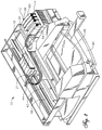
- Figure 2 is a isometric view of an ink-jet printer having several of the ink cartridges of Figure 1.
- Figure 3 is a isometric view of an ink supply station on the ink-jet printer of Figure 2.
- Figure 4 is a side view of the ink container of Figure 1.
- Figure 5 is a front view of the ink container of Figure 1.
- Figure 6 is a bottom view of the ink container of Figure 1.
- Figure 7 is a enlarged bottom view of the ink container of Figure 1, showing details of the electrical interconnect portion of the ink container.
- Figure 8 is an isometric view of a lower portion of the ink container of Figure 1, shown prior to engaging the electrical connector of the ink-jet printer of Figure 2.
- Figure 9 is an enlarged view of the electrical contacts and memory device of the ink container of Figure 1, showing traces between the contacts and the memory device being severed to disable the memory device.
- Figure 10 is an enlarged view of the electrical contacts of Figure 9, shown attached to a new source of signals.
- Figure 11 is an end isometric view of a second type of ink cartridge for refurbishment in accordance with this invention, the second type having a larger volume reservoir than the ink cartridge of Figures 1-10.
-
- Although the present invention comprises methods for electrically refurbishing ink containers for printing systems, the invention may be more clearly understood by first thoroughly discussing one of the printing systems for which this invention may be adapted.
- Figure 1 illustrates a portion of an ink-
jet printing system 10 having an original equipment ink cartridge orcontainer 12. The ink-jet printing system 10 includes an inkcontainer receiving station 14, an ink-jet printhead 16, and aprint controller 18. Printing is accomplished by the ejection of ink from theprinthead 16 under the control ofprint controller 18.Printhead 16 is connected to thecontroller 18 bylink 19 for controlling ejection of ink. Ink is provided to theprinthead 16 by way of afluid conduit 21, which joins theprinthead 16 to the receivingstation 14.Ink container 12 includes afluid outlet 20 which communicates with afluid reservoir 22.Ink container 12 also includes electrical terminals orcontacts 24 which communicate with aninformation storage device 26 such as a memory device. -
Fluid outlet 20 andelectrical contacts 24 allowink container 12 to interconnect with afluid inlet 28 andelectrical contacts 30, respectively, on receivingstation 14. Receivingstation 14 enables ink to be transferred fromfluid reservoir 22 toprinthead 16 viafluid conduit 21. In addition, receivingstation 14 allows the transfer of information betweeninformation storage device 26 andprint controller 18 via alink 32. - Referring now to Figure 2,
printer 10, with its cover removed, is capable of holding fourink containers 12 at the same time.Printer 10 includes atray 40 for holding a paper supply. When a printing operation is to be initiated, a sheet of paper fromtray 40 is fed intoprinter 10 using a sheet feeder (not shown). - During printing, the paper passes through a
print zone 42 whereupon ascanning carriage 44 containing one ormore printheads 16 is scanned across the sheet for printing a swath of ink thereon. The sheet of paper is stepped through theprint zone 42 as thescanning carriage 44 prints a series of swaths of ink to form images thereon. After printing is complete, the sheet is positioned into anoutput tray 46. The positioning ofpaper supply 40 andoutput tray 46 can vary depending on the particular sheet feed mechanism used. Scanningcarriage 44 slides through theprint zone 42 on a scanning mechanism which includes aslide rod 48. A positioning means such as a coded strip (not shown) is used in conjunction with a photo detector for precisely positioning scanningcarriage 44. A stepper motor (not shown), connected to scanningcarriage 44 using a conventional drive belt and pulley arrangement, is used for transportingscanning carriage 44 acrossprint zone 42. A ribbon cable (not shown) carries electrical signals to thescanning carriage 44 for selectively energizing the printheads 16 (Figures 1 and 2). As theprintheads 16 are selectively energized, ink of a selected color is ejected onto the print media as scanningcarriage 44 passes throughprint zone 42. - Each
ink container 12 has its ownelectrical contacts 24 and fluid outlet 20 (Figure 3).Ink containers 12 may be referred to as a off-axis ink supply since the ink supply is spaced from a scan axis defined by scanningcarriage 44. In the case of color printing,ink containers 12 are typically separate ink containers for each color with a container for black ink. For example,ink container 12 for the embodiment shown in Figure 2 is anink container 54 for black ink, anink container 56 for yellow ink, anink container 58 for magenta ink, and anink container 60 for cyan ink. Receivingstation 14 contains mechanical, fluid and electrical interfaces for eachink container 12. Ink passes through the fluid interfaces in receivingstation 14,fluid conduits 21 and then to printheads 16 onprint scanning carriage 44. - Referring to Figure 3, receiving
station 14 has four separate electrical connector posts 70, one for each of thecartridges 12. The fourelectrical contacts 30 are mounted to eachelectrical connector post 70, as shown in Figure 8. Eachconnector post 70 protrudes upwardly and has a taperedleading edge portion 71.Contacts 30 are outwardly spring biased fromconnector post 70. - Referring again to Figure 3, one of the
ink containers 12 is positioned for insertion into receivingstation 14 ofprinter 10.Ink container 12 contains a supply of media marking fluid such as ink. As described above,ink container 12 hasfluid outlet 20 andelectrical contacts 24. Also, as shown in Figure 7, ink container has aligningribs 62 on each side edge. Aligningribs 62 mate withslots 66 on receivingstation 14 to assist in aligningink container 12 for insertion into receivingstation 14. Aligningribs 62 andslots 66 also provide a keying function to ensure thatink container 12 contains ink having the proper parameters, such as color and ink compatibility withprinter 10. Ink container also has latch shoulders 64 on each side edge, as shown in Figure 3, which are engaged byresilient latches 68 mounted on the sidewalls of receivingstation 14. - Once
ink container 12 is aligned and inserted into receivingstation 14, latches 68 on receivingstation 14 engage corresponding latch shoulders 64 onink container 12. Insertion ofink container 12 into receivingstation 14 forms both electrical and fluid interconnects betweencontacts ports -
Ink container 12 is shown in detail in Figures 4-7.Ink container 12 includes an outer surface orhousing 72 having a leading edge or end 74 and a trailing edge or end 76 relative to the direction of insertion ofink container 12 into receivingstation 14. There are four terminals orcontacts 24 on the ink container, 24a for ground, 24b for clocking signals, 24c for power, and 24d for input and output data.Contacts 24 are located in asmall cavity 80 on a lower side ofhousing 72 adjacent to leadingedge 74. - Referring to Figure 9,
contacts 24 are metal conductive layers disposed on anon-conductive substrate 78 such as epoxy and fiberglass. Four traces or leads 81 are disposed onsubstrate 78, each extending from one of thecontacts 24.Memory device 26 is mounted tosubstrate 78, and the terminals ofmemory device 26 are joined to thetraces 81. This places terminals of thememory device 26 in electrical continuity withcontacts 24. A protective coating (not shown), such as epoxy, is used to encapsulatememory device 26 after its terminals are bonded to traces 81. A backside of thesubstrate 78, opposite thecontacts 24 andmemory device 26, is bonded by adhesive or swaged to a sidewall of cavity 80 (Figure 7). With theink container 12 properly inserted into the receivingstation 14,electrical contacts 24 associated with the ink container are positioned for engagement with electrical contacts 30 (Figure 8) associated with the receivingstation 14. - The entrance to
cavity 80 is sized to be small enough to reduce the possibility of fingers from enteringcavity 80. The proper sizing of the entrance is important for preventing contamination ofcontacts 24 during handling ofink container 12. Referring to Figure 8,cavity 80 closely receives one of the connector posts 70. Asink container 12 is inserted intoprinter 10,contacts 30 are compressed againstcontacts 24 to form a low resistance electrical connection betweenprinter 10 andmemory device 26. - Each
ink container 12 has ink related parameters which are unique to the particular ink container and the ink within the ink container. These parameters are stored in theinformation storage device 26 associated with theink container 12. The parameters in theinformation storage device 26 are provided to thecontroller 18 automatically without requiring the user to configureprinter 10 for theparticular ink container 12 installed.Memory device 26 has a read-only section, a write-once section, and a multiple write/erase section. The read only section is write enabled during the initial installation. When the cartridge is first installed in theprinter 10, theprinter 10 reads ink container information such as the manufacturer identity, part identification, date code of ink supply, system coefficients, service mode and ink supply size. Theprinter 10 then stores the installation date in the read only section ofstorage device 26, then initiates a write protect feature to assure that the information in the read-only section remains the same. The initial installation date is used by theprinter 10 to determine if an ink container has been installed for an extended period of time which, if long enough, can reduce print quality. - The write once section is a portion of memory which can be written to by
printer 10 only one time. The multiple write/erase section can be written to and erased repeatedly. Both of these sections deal with storing information concerning current ink quantity. As will be explained below, the coarse bit information is stored in the write once section and the fine bit data is stored in the multiple write/erase section. - Upon insertion of
ink container 12 intoprinting system 10,controller 18 reads parameter information frominformation storage device 26 for controlling various printing functions. For example,controller 18 uses parameter information to compute an estimate of remaining ink. If the ink remaining is less than a low ink threshold volume, a message is provided to the user indicating such. Further, when a substantial portion of the ink below the threshold volume is consumed,controller 18 can disableprinting system 10 to prevent operation of theprinthead 16 without a supply of ink.Printhead 16 operation without ink can result in reduction of printhead reliability or catastrophic failure of theprinthead 16.Controller 18 can also provide notice to the user when the ink is beyond its shelf life so thatink container 12 can be replaced to ensure maximum print quality. - In operation, the
printing system 10 reads initial volume information from thememory device 26 associated with theink container 12. As ink is used during printing this ink is monitored by theprinting system 10 and thememory device 26 is updated to contain information relating to remaining ink in theink container 12. Theprinting system 10 thereafter monitors the level of deliverable ink inink container 12 viamemory device 26. In a preferred embodiment, data is transferred between theprinter 10 and thememory device 26 in serial fashion using thesingle data line 24 relative to ground. - In a preferred embodiment, the volume information includes the following: (1) initial supply size data in a write protected portion of memory, (2) coarse ink level data stored in write once portion of memory, and (3) fine ink level data stored in a write/erase portion of memory. The initial supply size data is indicative of the amount of deliverable ink initially present in
ink container 12. - The coarse ink level data includes a number of write once bits that each correspond to some fraction of the deliverable ink initially present in
ink container 12. In a first preferred embodiment, eight coarse ink level bits each corresponding to one eighth of the deliverable ink initially inink container 12. In a second preferred embodiment, to be used in the discussion that follows, seven coarse ink level bits each correspond to one eighth of the deliverable ink initially present inink container 12 and one coarse ink level bit corresponds to an out of ink condition. However, more or less coarse bits can be used, depending on the accuracy desired for a coarse ink level counter. - The fine ink level data is indicative of a fine bit binary number that is proportional to a traction of one eighth of the volume of the deliverable ink initially present in
ink container 12. Thus, the entire range of the fine bit binary number is equivalent to one coarse ink level bit. This will be further explained below. -
Printing system 10 reads the initial supply size data and calculates the amount or volume of deliverable ink initially present inink container 12. The drop volume ejected by theprinthead 16 is determined by printingsystem 10 by reading parameters and/or performing calculations. Using the initial volume of deliverable ink inink container 12 and the drop volume ofprinthead 16, theprinting system 10 calculates the fraction of the initial deliverable ink volume that each drop represents. This enables theprinting system 10 to monitor the traction of the initial volume of deliverable ink remaining inink container 12. - While printing,
printing system 10 maintains a drop count equal to the number of ink drops that have been ejected byprinthead 16. After printingsystem 10 has printed a small amount, typically one page, it converts the drop count to a number of increments or decrements of the fine bit binary number. This conversion utilizes the fact that the entire range of the fine bit binary number corresponds to one eighth of the initial volume of deliverable ink inink container 12. Each time the fine bit binary number is fully decremented or incremented, theprinting system 10 writes to one of the coarse ink level bits to "latch down" the bit. -
Printing system 10 periodically queries the coarse and fine ink level bits to determine the fraction of the initial deliverable ink that is remaining inink container 12.Printing system 10 can then provide a "gas gauge" or other indication to a user ofprinting system 10 that is indicative of the ink level inink container 12. In a preferred embodiment, the printing system provides a "low ink warning" when seventh (second to last) coarse ink level bit is set. Also in a preferred embodiment, the printing system sets the last coarse ink level bit when theink container 12 is substantially depleted of ink. This last coarse ink level bit is referred to as an "ink out" bit. Upon querying the coarse ink level bits, the printing system interprets a "latched down" ink out bit as an "ink out" condition forink container 12. - In
printing system 10, the transfer of data betweenprinter 10 andmemory device 26 is in serial fashion on the single data line relative to ground. As explained above, while the ink inink container 12 is being depleted,memory device 26 stores data which is indicative of its initial and current states.Printer 10updates memory device 26 to indicate the volume of ink remaining. When most or substantially all of the deliverable ink has been depleted,printer 10 altersmemory device 26 to allowink container 12 to provide an "ink out" signal.Printer 10 may respond by stopping printing withink container 12. At that point, the user will insert anew ink container 12 or one that has been refilled and electrically refurbished in accordance with this invention. -
Ink container 12 is fluidically refurbished by refilling it with ink. After theink container 12 is partially depleted of ink, thememory device 26 that contains remaining ink. As explained above, the coarse bit counter reflecting remaining ink is stored in the write once section ofmemory 26. Consequently, refilling theink container 12 results in the alteration of the amount of ink remaining but does not change the coarse bit counter indicating the amount of remaining ink. Therefore, thememory device 26 does not provide accurate ink remaining information resulting in improper low ink condition signals. In addition, because the refilled ink does not have the same ink parameters as those ink parameters stored in thememory device 26 then theprinting system 10 can not properly compensate for this refilled ink to ensure high print quality. - The purpose of this invention is to electrically refurbish
ink container 12 so that the benefits previously provided bymemory device 26 still exist. In this invention, the pre-existing data inmemory device 26 is prevented from further communication withprinter 10 whencartridge 12 is installed again. In one technique, all of the data inmemory device 26 is erased. This can be accomplished by exposing thememory device 26 to a energy source such as an x-ray or electric field. This energy source, if sufficient, resets the data inmemory device 26. The reservoir ofink container 12 is then refilled. Thenmemory device 26 can be reprogrammed to reflect parameters of the refilledink container 12. When installed in theprinting system 10 the printing system operates with theink container 12 in a manner similar to the initial ink container. - In another refurbishment method,
memory device 26 is disabled and replaced with an identical one or with an emulator 84 (Fig. 10). Thenew memory device 26 may be an emulator or a substantial replica of theoriginal memory device 26.Emulator 84 is a electronic circuit that is functionally equivalent tomemory device 26 in providing information to printer 10 (Figure 1) although structurally this device may be very different.Emulator 84 would likely have a portion that functions as a memory and would likely provide information regarding the volume ofreservoir 22, the type of ink, color, etc. Optionally, unlikeoriginal memory device 26,emulator 84 may be reset in a different manner whenever a new ink supply is provided. Further,emulator 84 may be configured to provide information toprinter 10 which enables it to operate regardless of the actual condition of the ink inink reservoir 22. - The new source of signals, such as
emulator 84 or anew memory device 26, must be provided with the data required for proper operation ofprinter 10. The new source of signals must be able to communicate withprinter 10 over a single wire input/output in serial fashion. The data provided by thememory device 26 is used byprinter 10 to generate a indication of the volume of ink available. - In one technique for refurbishing
ink container 12, thefirst memory device 26 will be removed fromcavity 80 of housing 72 (Fig. 7). Substrate 78 (Fig. 9), along withmemory device 26 andcontacts 24, may be pried off or otherwise removed as a unit fromcavity 80. Anew substrate 78, having anew memory device 26 oremulator 84 andcontacts 24, may be adhesively bonded to a sidewall ofcavity 80 in the same place that held theoriginal substrate 78,memory device 26 andcontacts 24. Alternately, asubstrate 78 containing only a new set ofcontacts 24 may be mounted incavity 80. Thenew memory device 26 oremulator 84 may be mounted at another place onhousing 72 of refurbishedcartridge 12 and connected to the new set ofcontacts 24 by leads. As indicated in Figure 10,emulator 84 may also be located remotely from or not immediately adjacent toprinter 10 and connected byleads 82 tocontacts 24 withincavity 80. - Another refurbishment method allows the
original substrate 78,memory device 26 andcontacts 24 to remain in place. Anew substrate 78, along with anew memory device 26 andcontacts 24, will be bonded on top of theoriginal memory device 26 andcontacts 24. As the material ofsubstrate 78 is an electrical insulator, it will insulate thenew contacts 24 and traces 81 (Fig. 9) from theoriginal contacts 24 and traces 81. Theoriginal contacts 24 will not be able to electrically engage printer contacts 30 (Fig. 8) because they will be covered and insulated from engagement by thenew substrate 78. This technique may be performed several times before electrical connection withprinter 10 becomes difficult due to space constraints.Cavity 80 becomes effectively smaller each time anew substrate 78, along withnew contacts 24 and anew memory device 26, are installed on top of an earlier set. - In another refurbishment process, a usable portion of the
original contacts 24 remains in place and is electrically separated from theoriginal memory device 26. In this method, preferably a cut is made throughsubstrate 78 transversely across one ormore contacts 24 with a sharp object such asknife 85 as shown in Figure 9. The cut dividessubstrate 78 into retained anddisposable portions portion 78a of which contains a significant portion ofcontacts 24. Substratedisposable portion 78b containsmemory device 26, along withtraces 81 and a small adjacent part ofcontacts 24. This cut severs electrical continuity between the four terminals ofmemory device 26 with the part ofcontacts 24 contained on the substrate retainedportion 78a. Although, the size ofcontacts 24 on substrate retainedportion 78a would be smaller than theoriginal contacts 24, they are of adequate size to mate with printer contacts 30 (Figure 8). - Normally, one would then remove from
cavity 80 thedisposable substrate portion 78b, along with thefirst memory device 26, traces 81, and the part ofcontacts 24 contained thereon. Anew memory device 26 may then be mounted adjacent to or on theoriginal contacts 24 contained on the retainedsubstrate portion 78a, with its terminals connected to them. Optionally, thenew memory device 26 could be mounted elsewhere onhousing 72 other than cavity 80 (Fig. 7) or even remotely fromprinter 10 and connected tooriginal contacts 24 by leads. If anemulator 84 is used rather than thememory device 26, it too may be mounted onhousing 72 in a place other than incavity 80, or it may be mounted incavity 80 adjacent to or on substrate retainedportion 78a. Alternately, as illustrated in Figure 10, thecontacts 24 on substrate retainedportion 78a may be connected to leads 82 that are attached to a remotely locatedemulator 84.Contacts 24 may be connected to leads 82 or to leads or terminals of anew memory device 26 by soldering, wire bonding, TAB bonding, etc. - The above descriptions thus explain several ways to refurbish memory device 26: (1) erase and reprogram; (2) remove and replace the
entire substrate 78, along withcontacts 24 andmemory device 26; (3) mount anew substrate 78 along with anew memory device 26 andcontacts 24 on top of theoriginal substrate 78,contacts 24, andmemory device 26; (4) or sever theoriginal substrate 78 into retained anddisposable portions new memory device 26 oremulator 84 to thecontacts 24 on retainedportion 78a. The above descriptions also explain that the new source of signals could be an emulator 84 or asubstitute memory device 26. Theemulator 84 ornew memory device 26 may be mounted tohousing 72 incavity 80 or elsewhere, or they may be located remotely. - In addition to electrically refurbishing
ink container 12, it will also be refilled with ink. Various methods forrefilling ink container 12 are described in a patent application entitled "Ink Container Refurbishment Method" attorney docket number 10971937-1, filed concurrently with this application. Another type of ink cartridge that may be refurbished in accordance with this invention is illustrated in Figure 11.Cartridge 86 is used with a different printer (not shown) thanprinter 10 of Figures 1-10 and holds a larger volume of ink than cartridge 12 (Figure 1). Unlikecartridge 12,cartridge 86 has an inductive ink level sensor (not shown) as well as amemory device 87. The printing system with whichcartridge 86 is used identifies three phases of ink usage. During phase one, both fine and coarse counters are used as described above forprinter 10. Ink drops are counted and recorded in the fine counter portion ofmemory device 86. Each time the fine counter fully increments or decrements, another coarse counter bit will be set. During phase two, only the ink level sensor is used. At the start of phase three, the fine counter is reset and used in the same manner as during the first phase. When the final coarse counter bit is set, a "ink out" warning will be indicated to the printer. The three-phase arrangement is provided because the inductive ink level sensor provided withink container 86 is sufficiently accurate in the second phase but not in the first and third phases. -
Ink container 86 has ahousing 88 which contains an ink reservoir (not shown).Housing 88 has a leading end or edge 90 and trailing end or edge 92 relative to a direction of insertion into a printer (not shown). Leadingedge 90 includes anair inlet 94 and afluid outlet 96 which connect to the printer. - A plurality of
electrical contacts 98 are disposed within a receptacle on leadingend 90 for providing electrical connection betweenink container 86 and the printer. Originally,contacts 98 are electrically interconnected tomemory device 87 and to the ink volume sensor (not shown). The electrical refurbishment techniques described above forink container 12 are equally applicable toink container 86,information storage device 87 andcontacts 98. The new source of signals to replacememory device 87 may be a near duplicate to the original one or an emulator. - The invention has several advantages. The electrical refurbishment methods described allow ink containers which are otherwise single use to be reused while maintaining the electrical interconnect between the ink container and the printer.
- Although the present invention has been described with respect to the preferred embodiment where the
portion 16 theink container 12 is mounted off of theprint carriage 22 the present invention is suited for other printer configurations as well. For example, the ink container portion may each be mounted on theprinting carriage 22. For this configuration each of the printhead and the ink container portion are separately replaceable. Each of the printhead and the ink container includes astorage device 26 providing information to theprinter 10. Each ink container of a plurality of ink containers may be separately replaceable or replaceable as an integrated unit. For the case where the plurality of ink containers is integrated into a single replaceable printing component then only asingle storage device 26 is required for this single replaceable printing component.
Claims (17)
- A method of re-using an ink container (12) which is at least partially depleted of ink, the ink container (12) including a first memory device (26) associated with the ink container (12) for communication with a printer (10) when the ink container (12) is connected to the printer (10), the first memory device (26) containing first parameters relating to the ink contained in the ink container (12) while in its at least partially depleted condition, the method comprising:(a) refilling the ink container (12) with ink;(b) preventing the first parameters from further communication with the printer (10); and(c) electronically providing second parameters for communication with the printer (10) which relate to the ink container (12) when refilled.
- The method of claim 1 wherein step (c) comprises providing a second memory device (26) associated with the ink container (12) and storing the second parameters in the second memory device (26).
- The method of claim 1 wherein step (b) comprises:altering the first memory device (26) to remove the first parameters; and step (c) comprises:storing the second parameters in the first memory device (26).
- The method of claim 1 wherein (b) comprises:removing the first memory device (26) from the ink container (12); and step (c) comprises:providing a second memory device (26) associated with the ink container (12) and storing the second parameters in the second memory device (26).
- A method of re-using an ink container (12) having a reservoir (22) that has been at least partially depleted of ink, the ink container (12) having a first memory device (26) that is coupled to a plurality of ink container contacts (24) which engage mating printer contacts (30) of a printing system (10) upon installation of the ink container (12) into the printing system (10) for communicating between the first memory device (26) and the printing system (10), the first memory device (26) having been electrically altered during usage of ink from the ink container (12) such that it provides a remaining ink quantity signal to the printing system (10) indicative of at least a partially depleted state, the method comprising:(a) preventing the remaining ink quantity signal from communicating further with the printing system (10); and(b) providing a source of signals which when electrically connected to the printer contacts (30), provides a signal indicative of more available ink than the amount previously signaled by the remaining ink quantity signal prior to step (a).
- The method of claim 5 wherein step (b) comprises providing a second memory device (26) as the source of signals.
- The method of claim 5 wherein the first memory device (26) has write-once sectors of memory that have been altered by the printing system (10) to be indicative of ink usage; and wherein step (b) comprises:providing a second memory device (26) as the source of signals, the second memory device (26) having corresponding write-once sectors of memory that have not been altered by the printing system (10).
- The method of claim 5 wherein the ink container contacts (24) are disposed on an end of the ink container (12); and wherein step (b) comprises:mounting a second plurality of ink container contacts (24) on the end of the ink container (12) proximate to the same location as said first mentioned ink container contacts (24), such that upon installation of the ink container (12) into the printing system (10), the second plurality of ink container contacts (24) connect to the printer contacts (30).
- The method of claim 5 wherein step (a) comprises severing electrical continuity between the first memory device (26) and at least a portion of the ink container contacts (24); andstep (b) comprises connecting the source of signals to said at least a portion of the ink container contacts (24).
- The method of claim 5 wherein step (b) comprises providing an emulator (84) as the source of signals.
- A method for re-using a printer ink container (12) having an ink reservoir (22) that has been substantially depleted of ink, the ink container (12) having a first memory device (26) and a set of first contacts (24) for exchanging information with a printer (10) via an electrical connector (30) on the printer (10), the first memory device (26) having stored therein characteristics of the ink in the ink container (12) including the quantity of ink left in the substantially depleted condition, the printer (10) having a circuit (18) which reads information from the first memory device (26) to enable the printer (10) to operate and which provides ink usage information to the first memory device (26), the method comprising:(a) disabling the first memory device (26) on the ink container (12) such that the first memory device (26) may no longer provide information to the printing system (10); and(b) electrically connecting to the ink container (12) an electrical device (84) having a source of signals for providing enabling information to the printer (10) to enable the printer (10) to operate.
- The method of claim 11 wherein the first memory device (26) and the first contacts (24) are mounted to a first substrate (78) that is secured to the ink container (12), and wherein step (a) comprises:removing the first substrate (78) along with the first memory device (26) and the first contacts (24) from the ink container (12) by prying the first substrate (78) from the ink container (12).
- The method of claim 11 wherein:the first memory device (26) and the first contacts (24) are mounted to a first substrate (78) that is secured to the ink container (12);step (a) comprises severing the first substrate (78) into a retained portion and a disposable portion, with at least a portion of the first contacts (24) being located on the retained portion and the first memory device (26) being located on the disposable portion; andstep (b) comprises connecting the source of signals to said at least a portion of the ink container contacts (24) on the retained portion of the first substrate (78).
- The method of claim 11 wherein step (b) comprises providing the electrical device (84) with serial input/output circuitry so that input/output data, clocking requirements, electrical power and an electrical ground may be established between the electrical device (84) and the printer (10) when the ink container (12) is connected to the printer (10).
- The method of claim 11 wherein step (b) comprises providing the electrical device (84) with a memory portion to enable the circuit (18) of the printer (10) to write ink usage information to the memory portion.
- A refurbished ink container (12) for a printer (10), comprising:a reservoir (22) which is filled with a replacement ink which has replaced original ink stored therein; anda source of signals associated with the container (12) which is adapted to provide parameters relating to the replacement ink when electrically connected to the printer (10), the source of signals having a memory portion (26) which is capable of being written to by the printer (10) for storing information relating to usage of the replacement ink stored in the reservoir (22).
- The ink container (12) of claim 16 wherein the source of signals has a single data terminal (24d) and a reference terminal (24a), the source of signals adapted to be responsive to control signals received from the printer (10) on the single data terminal (24d) relative to the reference terminal (24a) for providing to the single data terminal (24d) relative to the reference terminal (24a) a data signal representative of stored information in the memory portion (26), the data signal adapted to be sensed by the printer (10).
Applications Claiming Priority (2)
| Application Number | Priority Date | Filing Date | Title |
|---|---|---|---|
| US34875 | 1998-03-04 | ||
| US09/034,875 US6227638B1 (en) | 1997-01-21 | 1998-03-04 | Electrical refurbishment for ink delivery system |
Publications (3)
| Publication Number | Publication Date |
|---|---|
| EP0940259A2 true EP0940259A2 (en) | 1999-09-08 |
| EP0940259A3 EP0940259A3 (en) | 1999-11-17 |
| EP0940259B1 EP0940259B1 (en) | 2004-06-02 |
Family
ID=21879146
Family Applications (1)
| Application Number | Title | Priority Date | Filing Date |
|---|---|---|---|
| EP99301566A Expired - Lifetime EP0940259B1 (en) | 1998-03-04 | 1999-03-02 | Electrical refurbishment for ink delivery system |
Country Status (6)
| Country | Link |
|---|---|
| US (1) | US6227638B1 (en) |
| EP (1) | EP0940259B1 (en) |
| JP (1) | JP3827879B2 (en) |
| KR (1) | KR100588924B1 (en) |
| CN (1) | CN1109606C (en) |
| DE (1) | DE69917694T2 (en) |
Cited By (21)
| Publication number | Priority date | Publication date | Assignee | Title |
|---|---|---|---|---|
| EP0940254A2 (en) * | 1998-03-04 | 1999-09-08 | Hewlett-Packard Company | Electrical storage device for a replaceable printing component |
| GB2346830A (en) * | 1998-11-26 | 2000-08-23 | Seiko Epson Corp | Ink cartridge with memory unit storing specific information relating to the cartridge in different data bit lengths |
| GB2354202A (en) * | 2000-08-07 | 2001-03-21 | Dynamic Cassette Int | Ink cartridge having a removable memory device thereon on which data may be inputted or altered by a data altering device |
| WO2002011986A2 (en) * | 2000-08-07 | 2002-02-14 | Dynamic Cassette International Ltd. | A printer cartridge kit and method |
| US6685298B2 (en) * | 2001-09-28 | 2004-02-03 | Hewlett-Packard Development Company, L.P. | Method and apparatus for preventing theft of replaceable printing components |
| US6923531B2 (en) | 1998-11-26 | 2005-08-02 | Seiko Epson Corporation | Ink cartridge with memory |
| US6969140B2 (en) | 1998-11-26 | 2005-11-29 | Seiko Epson Corporation | Printer and ink cartridge attached thereto |
| GB2427853A (en) * | 2005-06-30 | 2007-01-10 | Dynamic Cassette Int | An ink cartridge and a memory device |
| US7195346B1 (en) | 1998-11-02 | 2007-03-27 | Seiko Epson Corporation | Ink cartridge and printer using the same |
| EP1681166A3 (en) * | 1999-10-04 | 2007-08-15 | Seiko Epson Corporation | Recording apparatus, semiconductor device, and recording head apparatus |
| WO2008079482A2 (en) * | 2006-10-27 | 2008-07-03 | Static Control Components, Inc. | Method and apparatus for spoofing imaging devices |
| USRE41238E1 (en) | 1998-11-26 | 2010-04-20 | Seiko Epson Corporation | Printer and ink cartridge attached thereto |
| US7934822B2 (en) | 2001-04-03 | 2011-05-03 | Seiko Epson Corporation | Ink cartridge |
| US7954934B2 (en) | 1998-05-18 | 2011-06-07 | Seiko Epson Corporation | Ink-jet printing apparatus and ink cartridge therefor |
| US8100502B2 (en) | 2004-01-21 | 2012-01-24 | Silverbrook Research Pty Ltd | Printer cartridge incorporating printhead integrated circuit |
| US8109616B2 (en) | 2004-01-21 | 2012-02-07 | Silverbrook Research Pty Ltd | Cover assembly including an ink refilling actuator member |
| US8292406B2 (en) | 2004-01-21 | 2012-10-23 | Zamtec Limited | Inkjet printer with releasable print cartridge |
| US8366236B2 (en) | 2004-01-21 | 2013-02-05 | Zamtec Ltd | Print cartridge with printhead IC and multi-functional rotor element |
| US8434858B2 (en) | 2004-01-21 | 2013-05-07 | Zamtec Ltd | Cartridge unit for printer |
| EP2844487B1 (en) | 2012-04-30 | 2017-08-16 | Hewlett-Packard Development Company, L.P. | Flexible substrate with integrated circuit |
| WO2020023014A1 (en) * | 2018-07-23 | 2020-01-30 | Hewlett-Packard Development Company, L.P. | Detecting connections at fluidic interconnects |
Families Citing this family (41)
| Publication number | Priority date | Publication date | Assignee | Title |
|---|---|---|---|---|
| US7249831B2 (en) | 1995-04-27 | 2007-07-31 | Hewlett-Packard Development Company, L.P. | Ink container refurbishment system |
| KR100687945B1 (en) * | 1998-05-25 | 2007-02-27 | 세이코 엡슨 가부시키가이샤 | Ink cartridge, ink-jet printing apparatus, and refilling device, and method for operating refilling device |
| US6658219B1 (en) * | 1999-09-30 | 2003-12-02 | Fuji Photo Film Co., Ltd. | Method, device, system and recording medium for detecting improper cartridge, and cartridge |
| US6520615B1 (en) * | 1999-10-05 | 2003-02-18 | Hewlett-Packard Company | Thermal inkjet print head with integrated power supply fault protection circuitry for protection of firing circuitry |
| JP4510981B2 (en) * | 2000-02-29 | 2010-07-28 | セイコーエプソン株式会社 | Inkjet recording device |
| KR100413676B1 (en) * | 2000-07-20 | 2003-12-31 | 삼성전자주식회사 | Developer container of printer |
| US6796635B2 (en) * | 2000-10-11 | 2004-09-28 | Seiko Epson Corporation | Ink cartridge and inkjet printer |
| US6505926B1 (en) | 2001-08-16 | 2003-01-14 | Eastman Kodak Company | Ink cartridge with memory chip and method of assembling |
| JP3697247B2 (en) * | 2002-04-22 | 2005-09-21 | キヤノン株式会社 | Information processing apparatus, monitoring method, program, and storage medium |
| US6705713B2 (en) | 2002-07-18 | 2004-03-16 | Eastman Kodak Company | Disposable ink assemblage |
| US6712459B2 (en) | 2002-07-18 | 2004-03-30 | Eastman Kodak Company | Ink cartridge having shielded pocket for memory chip |
| US6715864B2 (en) | 2002-07-18 | 2004-04-06 | Eastman Kodak Company | Disposable ink supply bag having connector-fitting |
| US20040012660A1 (en) * | 2002-07-18 | 2004-01-22 | Eastman Kodak Company | Ink cartridge having connectable-disconnectable housing and ink supply bag |
| US6702435B2 (en) | 2002-07-18 | 2004-03-09 | Eastman Kodak Company | Ink cartridge having ink identifier oriented to provide ink identification |
| US6709093B2 (en) | 2002-08-08 | 2004-03-23 | Eastman Kodak Company | Ink cartridge in which ink supply bag held fast to housing |
| US6755501B2 (en) | 2002-08-08 | 2004-06-29 | Eastman Kodak Company | Alternative ink/cleaner cartridge |
| US6830323B2 (en) | 2002-08-13 | 2004-12-14 | Eastman Kodak Company | Restricting flash spread when welding housing halves of cartridge together |
| US6705714B1 (en) | 2002-08-21 | 2004-03-16 | Eastman Kodak Company | Ink cartridge having ink supply bag filled to less than capacity and folded in cartridge housing |
| US6837576B2 (en) | 2002-08-21 | 2005-01-04 | Eastman Kodak Company | Method of filling ink supply bag for ink cartridge |
| DE60308460T2 (en) * | 2002-09-20 | 2007-10-31 | Océ-Technologies B.V. | Ink tank and mounting base |
| US7589850B2 (en) * | 2002-12-30 | 2009-09-15 | Lexmark International, Inc. | Licensing method for use with an imaging device |
| DE10301256B3 (en) * | 2003-01-15 | 2004-09-09 | Pelikan Hardcopy Production Ag | Method for inserting a carrier board into a holding device on a cartridge or cartridge, and holding device therefor |
| US7063399B2 (en) * | 2003-06-25 | 2006-06-20 | Lexmark International, Inc. | Imaging apparatus and method for facilitating printing |
| US7099599B2 (en) * | 2003-08-15 | 2006-08-29 | Static Control Components, Inc. | System and method for port testing and configuration |
| US7592567B2 (en) * | 2003-09-11 | 2009-09-22 | Wazana Brothers International, Inc. | Apparatus and method for disassembling containers having thermoplastic joining surfaces |
| JP4254631B2 (en) * | 2004-06-25 | 2009-04-15 | ブラザー工業株式会社 | Buffer tank for inkjet printer and inkjet printer |
| JP2006075997A (en) * | 2004-09-07 | 2006-03-23 | Seiko Epson Corp | Reuse method of liquid cartridge |
| US20060190324A1 (en) * | 2005-02-24 | 2006-08-24 | Lexmark International, Inc. | Method for providing reduced cost imaging to customers |
| US7424245B2 (en) | 2005-10-19 | 2008-09-09 | Static Control Components, Inc. | Systems and methods for remanufacturing imaging components |
| US20080165214A1 (en) * | 2007-01-05 | 2008-07-10 | Kenneth Yuen | Ink cartridge fluid flow arrangements and methods |
| US20080165232A1 (en) * | 2007-01-10 | 2008-07-10 | Kenneth Yuen | Ink cartridge |
| US20080186187A1 (en) * | 2007-02-06 | 2008-08-07 | Christopher Alan Adkins | Ink tank having integrated rfid tag |
| US20080204528A1 (en) * | 2007-02-28 | 2008-08-28 | Kenneth Yuen | Ink cartridge |
| CN101486272B (en) * | 2008-01-15 | 2013-01-30 | 珠海纳思达电子科技有限公司 | Print head chip protector, ink cartridge thereof and control method |
| JP4824794B2 (en) * | 2009-07-09 | 2011-11-30 | シルバーブルック リサーチ ピーティワイ リミテッド | Printer having replenishment control interface |
| JP5891708B2 (en) * | 2011-10-28 | 2016-03-23 | セイコーエプソン株式会社 | Printing device |
| CN102768484B (en) * | 2012-07-16 | 2014-11-26 | 珠海艾派克微电子有限公司 | Information storage device of imaging device, and imaging box |
| CN107206798B (en) * | 2015-04-17 | 2019-03-26 | 惠普发展公司,有限责任合伙企业 | Printing equipment and supporting member for printing equipment |
| MX2020001166A (en) | 2018-01-31 | 2020-03-12 | Hewlett Packard Development Co | Print substance end-of-life predictions. |
| US20230104973A1 (en) * | 2020-03-19 | 2023-04-06 | Hewlett-Packard Development Company, L.P. | Printing fluid reservoirs fluidically coupled to bottle seats and charging ports |
| JP2022162689A (en) | 2021-04-13 | 2022-10-25 | 株式会社リコー | Consumables supply method, consumables storage container, image forming apparatus, and consumables storage container for recharging |
Family Cites Families (14)
| Publication number | Priority date | Publication date | Assignee | Title |
|---|---|---|---|---|
| JPS588352B2 (en) | 1977-11-04 | 1983-02-15 | 株式会社リコー | Inkjet recording device |
| US5068806A (en) | 1988-12-02 | 1991-11-26 | Spectra-Physics, Inc. | Method of determining useful life of cartridge for an ink jet printer |
| DE69034240T2 (en) | 1989-08-05 | 2008-01-10 | Canon K.K. | Ink jet recording device and ink cartridge therefor |
| JP3222454B2 (en) | 1990-02-02 | 2001-10-29 | キヤノン株式会社 | Ink tank cartridge |
| US5265315A (en) | 1990-11-20 | 1993-11-30 | Spectra, Inc. | Method of making a thin-film transducer ink jet head |
| IT1256844B (en) | 1992-06-08 | 1995-12-21 | Olivetti & Co Spa | METHOD AND DEVICE FOR THE RECOGNITION OF THE END-INK IN AN INK-JET PRINT HEAD. |
| IT1272076B (en) | 1993-12-16 | 1997-06-11 | Olivetti Canon Ind Spa | INK LEVEL MEASURING DEVICE OF A PRINTING MODULE INK JET |
| WO1996005061A1 (en) | 1994-08-09 | 1996-02-22 | Encad, Inc. | Printer ink cartridge |
| US5699091A (en) | 1994-12-22 | 1997-12-16 | Hewlett-Packard Company | Replaceable part with integral memory for usage, calibration and other data |
| CA2164536A1 (en) | 1995-01-03 | 1996-07-04 | William G. Hawkins | Ink supply identification system |
| US5721576A (en) | 1995-12-04 | 1998-02-24 | Hewlett-Packard Company | Refill kit and method for refilling an ink supply for an ink-jet printer |
| US5732751A (en) | 1995-12-04 | 1998-03-31 | Hewlett-Packard Company | Filling ink supply containers |
| CN1101315C (en) | 1995-12-18 | 2003-02-12 | 精工爱普生株式会社 | Printing apparatus and control method thereof |
| WO1998004414A1 (en) | 1996-07-30 | 1998-02-05 | Philips Electronics N.V. | Printing device |
-
1998
- 1998-03-04 US US09/034,875 patent/US6227638B1/en not_active Expired - Lifetime
-
1999
- 1999-01-08 CN CN99101042.6A patent/CN1109606C/en not_active Expired - Fee Related
- 1999-03-02 DE DE69917694T patent/DE69917694T2/en not_active Expired - Lifetime
- 1999-03-02 EP EP99301566A patent/EP0940259B1/en not_active Expired - Lifetime
- 1999-03-02 KR KR1019990006758A patent/KR100588924B1/en not_active IP Right Cessation
- 1999-03-04 JP JP05631699A patent/JP3827879B2/en not_active Expired - Fee Related
Cited By (57)
| Publication number | Priority date | Publication date | Assignee | Title |
|---|---|---|---|---|
| US6559973B2 (en) | 1998-03-04 | 2003-05-06 | Hewlett-Packard Company | Electrical storage device for a replaceable printing component |
| EP0940254A3 (en) * | 1998-03-04 | 2000-04-12 | Hewlett-Packard Company | Electrical storage device for a replaceable printing component |
| EP1745933A3 (en) * | 1998-03-04 | 2008-04-09 | Hewlett-Packard Company | Electrical storage device for a replaceable printing component |
| US6271928B1 (en) | 1998-03-04 | 2001-08-07 | Hewlett-Packard Company | Electrical storage device for a replaceable printing component |
| US6922259B2 (en) | 1998-03-04 | 2005-07-26 | Hewlett-Packard Development Company, L.P. | Electrical storage device for a replaceable printing component |
| EP0940254A2 (en) * | 1998-03-04 | 1999-09-08 | Hewlett-Packard Company | Electrical storage device for a replaceable printing component |
| US7954934B2 (en) | 1998-05-18 | 2011-06-07 | Seiko Epson Corporation | Ink-jet printing apparatus and ink cartridge therefor |
| US7393092B2 (en) | 1998-11-02 | 2008-07-01 | Seiko Epson Corporation | Ink cartridge and printer using the same |
| US7195346B1 (en) | 1998-11-02 | 2007-03-27 | Seiko Epson Corporation | Ink cartridge and printer using the same |
| US6447090B1 (en) | 1998-11-26 | 2002-09-10 | Seiko Epson Corp. | Ink cartridge and printer using the same |
| US7267415B2 (en) | 1998-11-26 | 2007-09-11 | Seiko Epson Corporation | Printer and ink cartridge attached thereto |
| USRE41377E1 (en) | 1998-11-26 | 2010-06-15 | Seiko Epson Corporation | Printer and ink cartridge attached thereto |
| GB2346830B (en) * | 1998-11-26 | 2003-05-21 | Seiko Epson Corp | Ink cartridge and printer using the same |
| USRE41238E1 (en) | 1998-11-26 | 2010-04-20 | Seiko Epson Corporation | Printer and ink cartridge attached thereto |
| GB2346830A (en) * | 1998-11-26 | 2000-08-23 | Seiko Epson Corp | Ink cartridge with memory unit storing specific information relating to the cartridge in different data bit lengths |
| US7134738B2 (en) | 1998-11-26 | 2006-11-14 | Seiko Epson Corporation | Printer and ink cartridge attached thereto |
| US6969140B2 (en) | 1998-11-26 | 2005-11-29 | Seiko Epson Corporation | Printer and ink cartridge attached thereto |
| US6923531B2 (en) | 1998-11-26 | 2005-08-02 | Seiko Epson Corporation | Ink cartridge with memory |
| US6955411B2 (en) | 1998-11-26 | 2005-10-18 | Seiko Epson Corporation | Ink cartridge and printer using the same |
| EP1681166A3 (en) * | 1999-10-04 | 2007-08-15 | Seiko Epson Corporation | Recording apparatus, semiconductor device, and recording head apparatus |
| GB2354202A (en) * | 2000-08-07 | 2001-03-21 | Dynamic Cassette Int | Ink cartridge having a removable memory device thereon on which data may be inputted or altered by a data altering device |
| EP1275510A3 (en) * | 2000-08-07 | 2004-09-29 | Dynamic Cassette International Limited | A printer cartridge kit and method |
| EP1179431A1 (en) * | 2000-08-07 | 2002-02-13 | Dynamic Cassette International Limited | A printer cartridge kit and method |
| WO2002011986A2 (en) * | 2000-08-07 | 2002-02-14 | Dynamic Cassette International Ltd. | A printer cartridge kit and method |
| EP1275510A2 (en) * | 2000-08-07 | 2003-01-15 | Dynamic Cassette International Limited | A printer cartridge kit and method |
| EP1598195A3 (en) * | 2000-08-07 | 2007-12-05 | Dynamic Cassette International Limited | A printer cartridge kit and method |
| EP1892102A2 (en) | 2000-08-07 | 2008-02-27 | Dynamic Cassette International Limited | A printer cartridge apparatus and method |
| EP1598195A2 (en) | 2000-08-07 | 2005-11-23 | Dynamic Cassette International Limited | A printer cartridge kit and method |
| WO2002011986A3 (en) * | 2000-08-07 | 2002-04-11 | Dynamic Cassette Int | A printer cartridge kit and method |
| EP1892102A3 (en) * | 2000-08-07 | 2008-07-02 | Dynamic Cassette International Limited | A printer cartridge apparatus and method |
| GB2354202B (en) * | 2000-08-07 | 2002-09-18 | Dynamic Cassette Int | A printer cartridge kit and method |
| US7934794B2 (en) | 2001-04-03 | 2011-05-03 | Seiko Epson Corporation | Ink cartridge |
| US7934822B2 (en) | 2001-04-03 | 2011-05-03 | Seiko Epson Corporation | Ink cartridge |
| US6685298B2 (en) * | 2001-09-28 | 2004-02-03 | Hewlett-Packard Development Company, L.P. | Method and apparatus for preventing theft of replaceable printing components |
| US6739691B2 (en) | 2001-09-28 | 2004-05-25 | Hewlett-Packard Development Company, L.P. | Method and apparatus for preventing theft of replaceable printing components |
| US8251501B2 (en) | 2004-01-21 | 2012-08-28 | Zamtec Limited | Inkjet print engine having printer cartridge incorporating maintenance assembly and cradle unit incorporating maintenance drive assembly |
| US8398216B2 (en) | 2004-01-21 | 2013-03-19 | Zamtec Ltd | Reservoir assembly for supplying fluid to printhead |
| US8292406B2 (en) | 2004-01-21 | 2012-10-23 | Zamtec Limited | Inkjet printer with releasable print cartridge |
| US8251499B2 (en) | 2004-01-21 | 2012-08-28 | Zamtec Limited | Securing arrangement for securing a refill unit to a print engine during refilling |
| US8100502B2 (en) | 2004-01-21 | 2012-01-24 | Silverbrook Research Pty Ltd | Printer cartridge incorporating printhead integrated circuit |
| US8109616B2 (en) | 2004-01-21 | 2012-02-07 | Silverbrook Research Pty Ltd | Cover assembly including an ink refilling actuator member |
| US8220900B2 (en) | 2004-01-21 | 2012-07-17 | Zamtec Limited | Printhead cradle having electromagnetic control of capper |
| US8235502B2 (en) | 2004-01-21 | 2012-08-07 | Zamtec Limited | Printer print engine with cradled cartridge unit |
| US8348386B2 (en) | 2004-01-21 | 2013-01-08 | Zamtec Ltd | Pagewidth printhead assembly with ink and data distribution |
| US8485651B2 (en) | 2004-01-21 | 2013-07-16 | Zamtec Ltd | Print cartrdge cradle unit incorporating maintenance assembly |
| US8439497B2 (en) | 2004-01-21 | 2013-05-14 | Zamtec Ltd | Image processing apparatus with nested printer and scanner |
| US8434858B2 (en) | 2004-01-21 | 2013-05-07 | Zamtec Ltd | Cartridge unit for printer |
| US8240825B2 (en) | 2004-01-21 | 2012-08-14 | Zamtec Limited | Ink refill unit having a clip arrangement for engaging with the print engine during refilling |
| US8366244B2 (en) | 2004-01-21 | 2013-02-05 | Zamtec Ltd | Printhead cartridge cradle having control circuitry |
| US8366236B2 (en) | 2004-01-21 | 2013-02-05 | Zamtec Ltd | Print cartridge with printhead IC and multi-functional rotor element |
| US8376533B2 (en) | 2004-01-21 | 2013-02-19 | Zamtec Ltd | Cradle unit for receiving removable printer cartridge unit |
| GB2427853A (en) * | 2005-06-30 | 2007-01-10 | Dynamic Cassette Int | An ink cartridge and a memory device |
| WO2008079482A2 (en) * | 2006-10-27 | 2008-07-03 | Static Control Components, Inc. | Method and apparatus for spoofing imaging devices |
| WO2008079482A3 (en) * | 2006-10-27 | 2008-10-16 | Static Control Components Inc | Method and apparatus for spoofing imaging devices |
| US8061794B2 (en) | 2006-10-27 | 2011-11-22 | Static Control Components, Inc. | Method and apparatus for spoofing imaging devices |
| EP2844487B1 (en) | 2012-04-30 | 2017-08-16 | Hewlett-Packard Development Company, L.P. | Flexible substrate with integrated circuit |
| WO2020023014A1 (en) * | 2018-07-23 | 2020-01-30 | Hewlett-Packard Development Company, L.P. | Detecting connections at fluidic interconnects |
Also Published As
| Publication number | Publication date |
|---|---|
| CN1227794A (en) | 1999-09-08 |
| KR100588924B1 (en) | 2006-06-09 |
| US6227638B1 (en) | 2001-05-08 |
| EP0940259B1 (en) | 2004-06-02 |
| CN1109606C (en) | 2003-05-28 |
| DE69917694T2 (en) | 2005-07-21 |
| JPH11291517A (en) | 1999-10-26 |
| JP3827879B2 (en) | 2006-09-27 |
| KR19990077516A (en) | 1999-10-25 |
| EP0940259A3 (en) | 1999-11-17 |
| DE69917694D1 (en) | 2004-07-08 |
Similar Documents
| Publication | Publication Date | Title |
|---|---|---|
| US6227638B1 (en) | Electrical refurbishment for ink delivery system | |
| US6170937B1 (en) | Ink container refurbishment method | |
| US6039430A (en) | Method and apparatus for storing and retrieving information on a replaceable printing component | |
| EP1060081B1 (en) | Ink container refurbishment system | |
| US6106088A (en) | Printhead assembly with integral lifetime monitoring system | |
| EP0968090B1 (en) | Ink container having electronic and mechanical features enabling plug compatibility between multiple supply sizes | |
| US6158837A (en) | Printer having print mode for non-qualified marking material | |
| US7249831B2 (en) | Ink container refurbishment system | |
| KR100613544B1 (en) | Ink delivery system adapter | |
| EP1745933B1 (en) | Electrical storage device for a replaceable printing component | |
| US7008050B2 (en) | Ink container refurbishment system | |
| EP1287997B1 (en) | Ink delivery system Adapter | |
| US6065824A (en) | Method and apparatus for storing information on a replaceable ink container | |
| KR100485565B1 (en) | Inkjet printer service station controlled by data from consumable parts with incorporated memory devices | |
| US6318850B1 (en) | Ink container refurbishment system | |
| US6312083B1 (en) | Printhead assembly with ink monitoring system | |
| EP0854043B1 (en) | Apparatus controlled by data from consumable parts with incorporated memory devices | |
| EP0720916A2 (en) | Ink supply identification system for a printer | |
| US20050168548A1 (en) | Systems and methods for refilling printing cartridges | |
| EP0878307A2 (en) | Mechanical and electrical keying arrangement for replaceable ink cartridge | |
| TW200307607A (en) | Recording liquid container and ink jet recording apparatus |
Legal Events
| Date | Code | Title | Description |
|---|---|---|---|
| PUAI | Public reference made under article 153(3) epc to a published international application that has entered the european phase |
Free format text: ORIGINAL CODE: 0009012 |
|
| AK | Designated contracting states |
Kind code of ref document: A2 Designated state(s): DE FR GB |
|
| AX | Request for extension of the european patent |
Free format text: AL;LT;LV;MK;RO;SI |
|
| PUAL | Search report despatched |
Free format text: ORIGINAL CODE: 0009013 |
|
| AK | Designated contracting states |
Kind code of ref document: A3 Designated state(s): AT BE CH CY DE DK ES FI FR GB GR IE IT LI LU MC NL PT SE |
|
| AX | Request for extension of the european patent |
Free format text: AL;LT;LV;MK;RO;SI |
|
| 17P | Request for examination filed |
Effective date: 20000118 |
|
| AKX | Designation fees paid |
Free format text: DE FR GB |
|
| RAP1 | Party data changed (applicant data changed or rights of an application transferred) |
Owner name: HEWLETT-PACKARD COMPANY, A DELAWARE CORPORATION |
|
| 17Q | First examination report despatched |
Effective date: 20021023 |
|
| GRAP | Despatch of communication of intention to grant a patent |
Free format text: ORIGINAL CODE: EPIDOSNIGR1 |
|
| GRAS | Grant fee paid |
Free format text: ORIGINAL CODE: EPIDOSNIGR3 |
|
| GRAA | (expected) grant |
Free format text: ORIGINAL CODE: 0009210 |
|
| AK | Designated contracting states |
Kind code of ref document: B1 Designated state(s): DE FR GB |
|
| REG | Reference to a national code |
Ref country code: GB Ref legal event code: FG4D |
|
| REF | Corresponds to: |
Ref document number: 69917694 Country of ref document: DE Date of ref document: 20040708 Kind code of ref document: P |
|
| ET | Fr: translation filed | ||
| PLBE | No opposition filed within time limit |
Free format text: ORIGINAL CODE: 0009261 |
|
| STAA | Information on the status of an ep patent application or granted ep patent |
Free format text: STATUS: NO OPPOSITION FILED WITHIN TIME LIMIT |
|
| 26N | No opposition filed |
Effective date: 20050303 |
|
| REG | Reference to a national code |
Ref country code: GB Ref legal event code: 732E Free format text: REGISTERED BETWEEN 20120329 AND 20120404 |
|
| PGFP | Annual fee paid to national office [announced via postgrant information from national office to epo] |
Ref country code: DE Payment date: 20130221 Year of fee payment: 15 Ref country code: GB Payment date: 20130228 Year of fee payment: 15 |
|
| PGFP | Annual fee paid to national office [announced via postgrant information from national office to epo] |
Ref country code: FR Payment date: 20130429 Year of fee payment: 15 |
|
| REG | Reference to a national code |
Ref country code: DE Ref legal event code: R119 Ref document number: 69917694 Country of ref document: DE |
|
| GBPC | Gb: european patent ceased through non-payment of renewal fee |
Effective date: 20140302 |
|
| REG | Reference to a national code |
Ref country code: FR Ref legal event code: ST Effective date: 20141128 |
|
| REG | Reference to a national code |
Ref country code: DE Ref legal event code: R119 Ref document number: 69917694 Country of ref document: DE Effective date: 20141001 |
|
| PG25 | Lapsed in a contracting state [announced via postgrant information from national office to epo] |
Ref country code: DE Free format text: LAPSE BECAUSE OF NON-PAYMENT OF DUE FEES Effective date: 20141001 Ref country code: FR Free format text: LAPSE BECAUSE OF NON-PAYMENT OF DUE FEES Effective date: 20140331 Ref country code: GB Free format text: LAPSE BECAUSE OF NON-PAYMENT OF DUE FEES Effective date: 20140302 |