EP0919154A2 - Hair dryer - Google Patents
Hair dryer Download PDFInfo
- Publication number
- EP0919154A2 EP0919154A2 EP98301736A EP98301736A EP0919154A2 EP 0919154 A2 EP0919154 A2 EP 0919154A2 EP 98301736 A EP98301736 A EP 98301736A EP 98301736 A EP98301736 A EP 98301736A EP 0919154 A2 EP0919154 A2 EP 0919154A2
- Authority
- EP
- European Patent Office
- Prior art keywords
- heater
- hair dryer
- ceramic material
- dryer according
- connection member
- Prior art date
- Legal status (The legal status is an assumption and is not a legal conclusion. Google has not performed a legal analysis and makes no representation as to the accuracy of the status listed.)
- Withdrawn
Links
Images


Classifications
-
- H—ELECTRICITY
- H05—ELECTRIC TECHNIQUES NOT OTHERWISE PROVIDED FOR
- H05B—ELECTRIC HEATING; ELECTRIC LIGHT SOURCES NOT OTHERWISE PROVIDED FOR; CIRCUIT ARRANGEMENTS FOR ELECTRIC LIGHT SOURCES, IN GENERAL
- H05B3/00—Ohmic-resistance heating
- H05B3/10—Heater elements characterised by the composition or nature of the materials or by the arrangement of the conductor
- H05B3/12—Heater elements characterised by the composition or nature of the materials or by the arrangement of the conductor characterised by the composition or nature of the conductive material
- H05B3/14—Heater elements characterised by the composition or nature of the materials or by the arrangement of the conductor characterised by the composition or nature of the conductive material the material being non-metallic
- H05B3/148—Silicon, e.g. silicon carbide, magnesium silicide, heating transistors or diodes
-
- A—HUMAN NECESSITIES
- A45—HAND OR TRAVELLING ARTICLES
- A45D—HAIRDRESSING OR SHAVING EQUIPMENT; EQUIPMENT FOR COSMETICS OR COSMETIC TREATMENTS, e.g. FOR MANICURING OR PEDICURING
- A45D20/00—Hair drying devices; Accessories therefor
- A45D20/04—Hot-air producers
- A45D20/08—Hot-air producers heated electrically
- A45D20/10—Hand-held drying devices, e.g. air douches
- A45D20/12—Details thereof or accessories therefor, e.g. nozzles, stands
-
- H—ELECTRICITY
- H05—ELECTRIC TECHNIQUES NOT OTHERWISE PROVIDED FOR
- H05B—ELECTRIC HEATING; ELECTRIC LIGHT SOURCES NOT OTHERWISE PROVIDED FOR; CIRCUIT ARRANGEMENTS FOR ELECTRIC LIGHT SOURCES, IN GENERAL
- H05B3/00—Ohmic-resistance heating
-
- H—ELECTRICITY
- H05—ELECTRIC TECHNIQUES NOT OTHERWISE PROVIDED FOR
- H05B—ELECTRIC HEATING; ELECTRIC LIGHT SOURCES NOT OTHERWISE PROVIDED FOR; CIRCUIT ARRANGEMENTS FOR ELECTRIC LIGHT SOURCES, IN GENERAL
- H05B3/00—Ohmic-resistance heating
- H05B3/10—Heater elements characterised by the composition or nature of the materials or by the arrangement of the conductor
- H05B3/12—Heater elements characterised by the composition or nature of the materials or by the arrangement of the conductor characterised by the composition or nature of the conductive material
- H05B3/14—Heater elements characterised by the composition or nature of the materials or by the arrangement of the conductor characterised by the composition or nature of the conductive material the material being non-metallic
- H05B3/141—Conductive ceramics, e.g. metal oxides, metal carbides, barium titanate, ferrites, zirconia, vitrous compounds
Definitions
- the present invention relates to a hair dryer comprising a heater.
- a conventional hair dryer is illustrated in Figure 1 and includes a body 1 containing a motor 5 for driving a fan 5a and a coil type heater 6 which is wound on a bracket 7. Air inlet ports 2 and a discharge port 3 are provided in the body to allow the flow of air therethrough.
- a handle 4 extends from the body 1 on which a switch 8 for controlling the operation of the hair dryer is mounted and a lead through which electrical current may be supplied to the hair dryer extends from a lower end of the handle.
- a plug (not shown) is attached to the free end of the lead 9 for insertion into an electrical supply socket.
- the heater 6 radiates heat and the fan, driven by the motor 5, draws air into the body 1 through the inflow ports 2 toward the heater 6. The air blown toward the heater 6 is thereby heated and discharged through the discharge ports 3.
- bracket 7 In addition to the aforementioned disadvantages, the bracket 7 must be quite large to accommodate the heater 6 which must be wound around the bracket many times to ensure its efficiency. This results in an increase in the overall size and weight of the hair dryer.
- the wire forming the coil of the heater 6 may eventually break after continuous use due to the repetition of supply and interruption of electrical power.
- a hair dryer according to the present invention is characterised in that the heater is formed from a ceramic material.
- the ceramic material is silicon carbide (SiC), lanthanum chromate (LaCrO 3 ) or zirconium dioxide (ZrO 2 ).
- the ceramic material may contain metal powder.
- the hair dryer includes a body and an insulating member disposed between the heater and the body.
- the hair dryer according to the present invention has a body 10, a motor 15, a fan 15a, a grip 14, a switch 18, and a cord 19, as does a conventional hair dryer of the type illustrated in Figure 1.
- the heater 20 may also be manufactured with a compound material comprising a ceramic material and metal powder.
- the heater 20 is disc shaped to conform with the shape of the body 10, and has a webbed construction.
- the heater 20 is disposed so that air blown by the fan 15a is discharged through the discharge port 13 via the heater 20.
- the heater 20 is surrounded by a member 23 which has a pair of connection terminals 26, each having a pair of holes 25a and 25b.
- the hole 25a formed in the outer edge of the connection terminal 26 is used to fix the connection member 23 to the body 10 by means of screw, and the hole 25b formed in the inner edge of the connection terminal 26 is used to connect the connection terminal to the electrical cord 19.
- the hair dryer has a control portion 30 for controlling the supply of electrical power from a power supply portion 29, a heat-radiating portion 40 for radiating heat, and a blowing portion 50 for blowing air toward the heater 20.
- the control portion 30 comprises a filter 31 for reducing electrical noise, a fuse 33 for preventing the hair dryer form overloading and a user operated switch 18 for controlling the supply of electric power to the heater 20 and the motor 15.
- the heat-radiating portion comprises a bimetal switch 41 and the heater 20.
- the heater 20 radiates heat when the switch 19 is turned on, and the bimetal switch 41 prevents the heater 20 from overheating by disconnecting the supply of electrical power to the heater 20.
- the blowing portion 50 comprises a voltage divider 51, a rectifier 53, and a motor 15.
- the electrical power supplied from the power supply portion 29 is stepped down to an appropriate voltage and is then rectified into a direct current.
- the voltage rectified from the rectifier 53 is applied to the motor 15, to drive fan 15a.
- the heater 20 radiates heat and the fan 15a operates to into the body 10 through the inflow ports 12 and blow it toward the heater 20.
- the heater 20 heats the air before it is discharged through the discharge port 13.
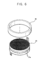
- FIG. 5 A second embodiment is illustrated in Figures 5 and 6.
- a pair of ribs 61 are provided within the body between which the connection member 23a fits.
- a ring-shaped insulation member 60 is disposed between the ribs and insulates the heater 20 from the body 20 so that the heat generated from the heater 20 is not transferred to the body 20 through the connection member 23a which could otherwise cause deformation of the body 20.
- the insulation member 60 is made of mica.
- the heater 20 is disc shaped rather than having a webbed construction. It is formed with a plurality of holes 21 through which air blown by the fan 15a passes as it travels towards the discharge port 13.
- the heater 20 of this embodiment is easier to manufacture than previously described embodiments.
- a heater 20 is made of a heat-radiating ceramic material, it is no longer necessary to wind a coil of wire around on a bracket and so the manufacturing process is simplified. In addition, the ceramic heater is small and light in comparison with a coil type heater, so the weight and size of the hair dryer can be reduced.
- the heater 20 can maintain continuous heat intensity, and overheating is prevented by the bimetal switch 41.
- the ceramic heater 20 heats up much faster than conventional heaters.
Landscapes
- Chemical & Material Sciences (AREA)
- Engineering & Computer Science (AREA)
- Ceramic Engineering (AREA)
- Cleaning And Drying Hair (AREA)
- Compositions Of Oxide Ceramics (AREA)
Abstract
Description
- The present invention relates to a hair dryer comprising a heater.
- A conventional hair dryer is illustrated in Figure 1 and includes a body 1 containing a
motor 5 for driving afan 5a and acoil type heater 6 which is wound on abracket 7.Air inlet ports 2 and adischarge port 3 are provided in the body to allow the flow of air therethrough. - A
handle 4 extends from the body 1 on which aswitch 8 for controlling the operation of the hair dryer is mounted and a lead through which electrical current may be supplied to the hair dryer extends from a lower end of the handle. A plug (not shown) is attached to the free end of thelead 9 for insertion into an electrical supply socket. - When the hair dryer is in use, the
heater 6 radiates heat and the fan, driven by themotor 5, draws air into the body 1 through theinflow ports 2 toward theheater 6. The air blown toward theheater 6 is thereby heated and discharged through thedischarge ports 3. - A problem with a conventional hair dryer of the type discussed above, is that the
heater 6 and thebracket 7 on which the heater is wound, are manufactured separately. Furthermore, the process of winding theheater 6 onto thebracket 7 must be done manually. This results in a complex manufacturing process and increased costs. - In addition to the aforementioned disadvantages, the
bracket 7 must be quite large to accommodate theheater 6 which must be wound around the bracket many times to ensure its efficiency. This results in an increase in the overall size and weight of the hair dryer. - Furthermore, it is difficult to accurately and finely control the temperature of the heated air using a conventional heater, which can result in hair damage caused by overheating. Also, the wire forming the coil of the
heater 6 may eventually break after continuous use due to the repetition of supply and interruption of electrical power. - Finally, it takes a considerable length of time for the heater of a conventional hair dryer to reach the required operating temperature resulting in an increase in consumption of electrical power whilst the hair dryer is not being used.
- It is an object of the present invention to overcome or substantially alleviate the disadvantages referred to above.
- A hair dryer according to the present invention is characterised in that the heater is formed from a ceramic material.
- Preferably, the ceramic material is silicon carbide (SiC), lanthanum chromate (LaCrO3) or zirconium dioxide (ZrO2).
- In one embodiment, the ceramic material may contain metal powder.
- In a preferred embodiment, the hair dryer includes a body and an insulating member disposed between the heater and the body.
- Embodiments of the present invention will now be described, by way of example only, with reference to the accompanying drawings, in which:
- Figure 1 is side sectional view of a conventional hair dryer;
- Figure 2 is a side sectional view of a hair dryer according to a first embodiment of the present invention;
- Figure 3 is a perspective view of the heater shown in Figure 2;
- Figure 4 is a block diagram of the hair dryer according to an embodiment of the present invention;
- Figure 5 is a side sectional view of a hair dryer according to another embodiment of the present invention;
- Figure 6 is a perspective view of the heater shown in Figure 5;
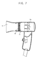
- Figure 7 is a perspective view of a hair dryer according to yet another embodiment of the present invention.
-
- The hair dryer according to the present invention has a
body 10, amotor 15, afan 15a, agrip 14, aswitch 18, and acord 19, as does a conventional hair dryer of the type illustrated in Figure 1. - A
heater 20 made from a heat-radiating ceramic material such as silicon carbide (SiC), lanthanum chromate (LaCrO3), or zirconium dioxide (ZrO2) is mounted within thebody 10. Theheater 20 may also be manufactured with a compound material comprising a ceramic material and metal powder. - The
heater 20 is disc shaped to conform with the shape of thebody 10, and has a webbed construction. Theheater 20 is disposed so that air blown by thefan 15a is discharged through thedischarge port 13 via theheater 20. - The
heater 20 is surrounded by amember 23 which has a pair ofconnection terminals 26, each having a pair ofholes hole 25a formed in the outer edge of theconnection terminal 26 is used to fix theconnection member 23 to thebody 10 by means of screw, and thehole 25b formed in the inner edge of theconnection terminal 26 is used to connect the connection terminal to theelectrical cord 19. - A block diagram of the hair dryer is illustrated in Figure 4. The hair dryer has a
control portion 30 for controlling the supply of electrical power from apower supply portion 29, a heat-radiatingportion 40 for radiating heat, and a blowingportion 50 for blowing air toward theheater 20. - The
control portion 30 comprises afilter 31 for reducing electrical noise, afuse 33 for preventing the hair dryer form overloading and a user operatedswitch 18 for controlling the supply of electric power to theheater 20 and themotor 15. - The heat-radiating portion comprises a
bimetal switch 41 and theheater 20. Theheater 20 radiates heat when theswitch 19 is turned on, and thebimetal switch 41 prevents theheater 20 from overheating by disconnecting the supply of electrical power to theheater 20. - The blowing
portion 50 comprises avoltage divider 51, arectifier 53, and amotor 15. The electrical power supplied from thepower supply portion 29 is stepped down to an appropriate voltage and is then rectified into a direct current. The voltage rectified from therectifier 53 is applied to themotor 15, to drivefan 15a. - When the
switch 18 is operated theheater 20 radiates heat and thefan 15a operates to into thebody 10 through theinflow ports 12 and blow it toward theheater 20. Theheater 20 heats the air before it is discharged through thedischarge port 13. - A second embodiment is illustrated in Figures 5 and 6. In this embodiment a pair of
ribs 61 are provided within the body between which theconnection member 23a fits. - A ring-
shaped insulation member 60 is disposed between the ribs and insulates theheater 20 from thebody 20 so that the heat generated from theheater 20 is not transferred to thebody 20 through theconnection member 23a which could otherwise cause deformation of thebody 20. Theinsulation member 60 is made of mica. - In a third embodiment illustrated in Figure 7, the
heater 20 is disc shaped rather than having a webbed construction. It is formed with a plurality ofholes 21 through which air blown by thefan 15a passes as it travels towards thedischarge port 13. Theheater 20 of this embodiment is easier to manufacture than previously described embodiments. - A
heater 20 is made of a heat-radiating ceramic material, it is no longer necessary to wind a coil of wire around on a bracket and so the manufacturing process is simplified. In addition, the ceramic heater is small and light in comparison with a coil type heater, so the weight and size of the hair dryer can be reduced. - Furthermore, the
heater 20 can maintain continuous heat intensity, and overheating is prevented by thebimetal switch 41. - Moreover, as there is no coil, malfunctions are reduced. Additionally, the
ceramic heater 20 heats up much faster than conventional heaters. - Although the present invention has been described and illustrated in detail, it is clearly understood that the same is by way of illustration and example only and is not to be taken by way of limitation, wherein the scope of the present invention is limited only by the terms of the appended claims.
Claims (15)
- A hair dryer comprising a heater (20), characterised in that the heater (20) is formed from a ceramic material.
- A hair dryer according to claim 1, wherein the ceramic material is silicon carbide (SiC), lanthanum chromate (LaCrO3) or zirconium dioxide (ZrO2).
- A hair dryer according to claim 1 or 2, wherein the ceramic material contains metal powder.
- A hair dryer according to any preceding claim, wherein the heater (20) has a webbed construction.
- A hair dryer according to any of claims 1 to 3, wherein the heater (20) has a plurality of holes extending through it.
- A hair dryer according to any preceding claim, comprising a body (10) and an insulating member disposed between the heater (20) and the body (10).
- A hair dryer according to any preceding claim, comprising a bimetallic switch (41) for terminating power to the heater (20) when a predetermined temperature has been reached.
- A hair dryer comprising:a body being formed with an inflow port and a discharge port;a heater made of a heat-radiating ceramic material;a connection member being installed on a side of said heater, said connection member for connecting said heater with an external power source; anda fan for blowing air flowing into said body through the inflow port and for discharging air heated by said heater through the discharge port.
- The hair dryer as claimed in claim 8, wherein said ceramic material is selected from a group consisting of silicon carbide (SiC), lanthanum chromate (LaCrO3), and zirconium dioxide (ZrO2).
- The hair dryer as claimed in claim 9, wherein metal powder is combined with said ceramic material.
- The hair dryer as claimed in claim 8, wherein said heater is formed into a web shape.
- The hair dryer as claimed in claim 8, wherein said heater is formed with a plurality of holes.
- The hair dryer as claimed in claim 8, wherein said connection member is fixed at an inner side of said body, and an insulation member is disposed between said connection member and said body.
- The hair dryer as claimed in claim 13, wherein said insulation material is mica.
- The hair dryer as claimed in claim 8, further comprising a bimetal switch for interrupting a supply of electrical power to said heater when a temperature of said heater rises higher than a predetermined temperature.
Applications Claiming Priority (6)
| Application Number | Priority Date | Filing Date | Title |
|---|---|---|---|
| KR9764502 | 1997-11-29 | ||
| KR1019970064502A KR19990043490A (en) | 1997-11-29 | 1997-11-29 | Hair Dryer Using Ceramic Heater |
| KR9764511 | 1997-11-29 | ||
| KR1019970064512A KR19990043500A (en) | 1997-11-29 | 1997-11-29 | Hair dryer |
| KR9764512 | 1997-11-29 | ||
| KR1019970064511A KR19990043499A (en) | 1997-11-29 | 1997-11-29 | Hair dryer |
Publications (2)
| Publication Number | Publication Date |
|---|---|
| EP0919154A2 true EP0919154A2 (en) | 1999-06-02 |
| EP0919154A3 EP0919154A3 (en) | 2001-01-24 |
Family
ID=27349641
Family Applications (1)
| Application Number | Title | Priority Date | Filing Date |
|---|---|---|---|
| EP98301736A Withdrawn EP0919154A3 (en) | 1997-11-29 | 1998-03-10 | Hair dryer |
Country Status (3)
| Country | Link |
|---|---|
| EP (1) | EP0919154A3 (en) |
| JP (1) | JPH11169225A (en) |
| CN (1) | CN1218649A (en) |
Cited By (1)
| Publication number | Priority date | Publication date | Assignee | Title |
|---|---|---|---|---|
| EP1836919A1 (en) * | 2006-03-23 | 2007-09-26 | Vertex Precision Electronics Inc. | Heat generating mechanism for hair dryer |
Families Citing this family (7)
| Publication number | Priority date | Publication date | Assignee | Title |
|---|---|---|---|---|
| DE10002984C1 (en) * | 2000-01-24 | 2001-08-09 | Daimler Chrysler Ag | Acoustic absorber and method for sound absorption |
| WO2006055946A1 (en) * | 2004-11-19 | 2006-05-26 | Conair Corporation | Hair dryers containing high-watt density ceramic heaters |
| CN101420795B (en) * | 2007-10-25 | 2010-10-13 | 正泰股份有限公司 | Heating module fixing construction for blower |
| WO2012019357A1 (en) * | 2010-08-13 | 2012-02-16 | Liu Qianren | Hair dryer without handle |
| KR101450334B1 (en) * | 2013-02-18 | 2014-10-14 | 주식회사 토야테크 | A Heat Generator using Silicon Carbide Ceramic Heater of Honeycomb Structure |
| CN104093225A (en) * | 2014-06-17 | 2014-10-08 | 梁卫兵 | Blower heating component structure |
| CN113712363A (en) * | 2021-08-13 | 2021-11-30 | 珠海市佳一陶瓷有限公司 | Electric hair drier |
Citations (5)
| Publication number | Priority date | Publication date | Assignee | Title |
|---|---|---|---|---|
| US3927300A (en) * | 1973-03-09 | 1975-12-16 | Ngk Insulators Ltd | Electric fluid heater and resistance heating element therefor |
| US4316077A (en) * | 1975-12-31 | 1982-02-16 | Texas Instruments Incorporated | Elastic hair dryer having selectively variable air output temperature |
| US4647757A (en) * | 1985-04-30 | 1987-03-03 | Clairol Incorporated | Hair dryer heater section providing uniform outlet air temperature distribution |
| US5023744A (en) * | 1988-05-20 | 1991-06-11 | Hofsass P | Temperature switching device |
| US5039843A (en) * | 1986-01-16 | 1991-08-13 | Limitor Ag | Safety cutout device |
-
1998
- 1998-03-10 EP EP98301736A patent/EP0919154A3/en not_active Withdrawn
- 1998-03-10 JP JP5863998A patent/JPH11169225A/en active Pending
- 1998-03-10 CN CN 98105400 patent/CN1218649A/en active Pending
Patent Citations (5)
| Publication number | Priority date | Publication date | Assignee | Title |
|---|---|---|---|---|
| US3927300A (en) * | 1973-03-09 | 1975-12-16 | Ngk Insulators Ltd | Electric fluid heater and resistance heating element therefor |
| US4316077A (en) * | 1975-12-31 | 1982-02-16 | Texas Instruments Incorporated | Elastic hair dryer having selectively variable air output temperature |
| US4647757A (en) * | 1985-04-30 | 1987-03-03 | Clairol Incorporated | Hair dryer heater section providing uniform outlet air temperature distribution |
| US5039843A (en) * | 1986-01-16 | 1991-08-13 | Limitor Ag | Safety cutout device |
| US5023744A (en) * | 1988-05-20 | 1991-06-11 | Hofsass P | Temperature switching device |
Cited By (1)
| Publication number | Priority date | Publication date | Assignee | Title |
|---|---|---|---|---|
| EP1836919A1 (en) * | 2006-03-23 | 2007-09-26 | Vertex Precision Electronics Inc. | Heat generating mechanism for hair dryer |
Also Published As
| Publication number | Publication date |
|---|---|
| CN1218649A (en) | 1999-06-09 |
| EP0919154A3 (en) | 2001-01-24 |
| JPH11169225A (en) | 1999-06-29 |
Similar Documents
| Publication | Publication Date | Title |
|---|---|---|
| US4647757A (en) | Hair dryer heater section providing uniform outlet air temperature distribution | |
| EP1714577A2 (en) | Hot air blower with ceramic heating element | |
| US20040159002A1 (en) | Hair dryer with infrared source | |
| EP0919154A2 (en) | Hair dryer | |
| KR100503262B1 (en) | Drying device for hair | |
| JP4554872B2 (en) | Blower | |
| JP2007190319A (en) | Hair dryer | |
| KR20170030684A (en) | a hair dryer | |
| KR19990043501A (en) | Hair dryer | |
| KR102181008B1 (en) | Wireless hair dryer of using surface heating element | |
| JPH10253163A (en) | Thermal storage electric hot air machine | |
| CN213119510U (en) | Electric fan | |
| JP6344431B2 (en) | Hair dryer | |
| KR19990043496A (en) | Hair dryer | |
| KR19990043500A (en) | Hair dryer | |
| KR200392866Y1 (en) | Hair drier | |
| KR19990043498A (en) | Hair dryer | |
| CN219020446U (en) | Low-radiation electric hair drier | |
| EP0338604A1 (en) | Conical shaped high performance electric resistance for hair driers and similar appliances | |
| KR0133628Y1 (en) | Hair dryer | |
| KR100501915B1 (en) | Hair dryer | |
| KR19990043499A (en) | Hair dryer | |
| KR200218211Y1 (en) | Electric heater | |
| KR200166429Y1 (en) | A drier for the car | |
| KR200338837Y1 (en) | Hair dryer |
Legal Events
| Date | Code | Title | Description |
|---|---|---|---|
| PUAI | Public reference made under article 153(3) epc to a published international application that has entered the european phase |
Free format text: ORIGINAL CODE: 0009012 |
|
| AK | Designated contracting states |
Kind code of ref document: A2 Designated state(s): AT BE CH DE DK ES FI FR GB GR IE IT LI LU MC NL PT SE |
|
| AX | Request for extension of the european patent |
Free format text: AL;LT;LV;MK;RO;SI |
|
| PUAL | Search report despatched |
Free format text: ORIGINAL CODE: 0009013 |
|
| AK | Designated contracting states |
Kind code of ref document: A3 Designated state(s): AT BE CH DE DK ES FI FR GB GR IE IT LI LU MC NL PT SE |
|
| AX | Request for extension of the european patent |
Free format text: AL;LT;LV;MK;RO;SI |
|
| STAA | Information on the status of an ep patent application or granted ep patent |
Free format text: STATUS: THE APPLICATION IS DEEMED TO BE WITHDRAWN |
|
| 18D | Application deemed to be withdrawn |
Effective date: 20001003 |