EP0918364B1 - Phosphate additives for non-aqueous electrolyte in alkali metal electrochemical cells - Google Patents
Phosphate additives for non-aqueous electrolyte in alkali metal electrochemical cells Download PDFInfo
- Publication number
- EP0918364B1 EP0918364B1 EP98308674A EP98308674A EP0918364B1 EP 0918364 B1 EP0918364 B1 EP 0918364B1 EP 98308674 A EP98308674 A EP 98308674A EP 98308674 A EP98308674 A EP 98308674A EP 0918364 B1 EP0918364 B1 EP 0918364B1
- Authority
- EP
- European Patent Office
- Prior art keywords
- pulse
- phosphate
- electrochemical cell
- cell according
- anode
- Prior art date
- Legal status (The legal status is an assumption and is not a legal conclusion. Google has not performed a legal analysis and makes no representation as to the accuracy of the status listed.)
- Expired - Lifetime
Links
- 239000000654 additive Substances 0.000 title claims description 72
- 229910019142 PO4 Inorganic materials 0.000 title claims description 47
- 239000010452 phosphate Substances 0.000 title claims description 47
- NBIIXXVUZAFLBC-UHFFFAOYSA-K phosphate Chemical compound [O-]P([O-])([O-])=O NBIIXXVUZAFLBC-UHFFFAOYSA-K 0.000 title claims description 40
- 229910052783 alkali metal Inorganic materials 0.000 title claims description 31
- 150000001340 alkali metals Chemical class 0.000 title claims description 27
- 239000011255 nonaqueous electrolyte Substances 0.000 title claims description 10
- 230000000996 additive effect Effects 0.000 claims description 52
- 239000003792 electrolyte Substances 0.000 claims description 45
- HDFFVHSMHLDSLO-UHFFFAOYSA-M dibenzyl phosphate Chemical compound C=1C=CC=CC=1COP(=O)([O-])OCC1=CC=CC=C1 HDFFVHSMHLDSLO-UHFFFAOYSA-M 0.000 claims description 36
- 239000000203 mixture Substances 0.000 claims description 36
- -1 cyclic ester Chemical class 0.000 claims description 30
- 229910052744 lithium Inorganic materials 0.000 claims description 23
- WHXSMMKQMYFTQS-UHFFFAOYSA-N Lithium Chemical compound [Li] WHXSMMKQMYFTQS-UHFFFAOYSA-N 0.000 claims description 21
- 239000002904 solvent Substances 0.000 claims description 20
- 229910052751 metal Inorganic materials 0.000 claims description 14
- 239000000463 material Substances 0.000 claims description 13
- 239000002184 metal Substances 0.000 claims description 13
- 230000036278 prepulse Effects 0.000 claims description 13
- 239000006182 cathode active material Substances 0.000 claims description 12
- XTHFKEDIFFGKHM-UHFFFAOYSA-N Dimethoxyethane Chemical compound COCCOC XTHFKEDIFFGKHM-UHFFFAOYSA-N 0.000 claims description 11
- 229910003455 mixed metal oxide Inorganic materials 0.000 claims description 11
- PXHVJJICTQNCMI-UHFFFAOYSA-N Nickel Chemical compound [Ni] PXHVJJICTQNCMI-UHFFFAOYSA-N 0.000 claims description 10
- RUOJZAUFBMNUDX-UHFFFAOYSA-N propylene carbonate Chemical group CC1COC(=O)O1 RUOJZAUFBMNUDX-UHFFFAOYSA-N 0.000 claims description 9
- 150000003839 salts Chemical class 0.000 claims description 9
- OKTJSMMVPCPJKN-UHFFFAOYSA-N Carbon Chemical group [C] OKTJSMMVPCPJKN-UHFFFAOYSA-N 0.000 claims description 8
- 229910001540 lithium hexafluoroarsenate(V) Inorganic materials 0.000 claims description 8
- RAVDHKVWJUPFPT-UHFFFAOYSA-N silver;oxido(dioxo)vanadium Chemical group [Ag+].[O-][V](=O)=O RAVDHKVWJUPFPT-UHFFFAOYSA-N 0.000 claims description 8
- 230000003213 activating effect Effects 0.000 claims description 7
- 125000004435 hydrogen atom Chemical group [H]* 0.000 claims description 7
- WEVYAHXRMPXWCK-UHFFFAOYSA-N Acetonitrile Chemical compound CC#N WEVYAHXRMPXWCK-UHFFFAOYSA-N 0.000 claims description 6
- RTZKZFJDLAIYFH-UHFFFAOYSA-N Diethyl ether Chemical compound CCOCC RTZKZFJDLAIYFH-UHFFFAOYSA-N 0.000 claims description 6
- SECXISVLQFMRJM-UHFFFAOYSA-N N-Methylpyrrolidone Chemical compound CN1CCCC1=O SECXISVLQFMRJM-UHFFFAOYSA-N 0.000 claims description 6
- WYURNTSHIVDZCO-UHFFFAOYSA-N Tetrahydrofuran Chemical group C1CCOC1 WYURNTSHIVDZCO-UHFFFAOYSA-N 0.000 claims description 6
- 125000000962 organic group Chemical group 0.000 claims description 6
- 230000002829 reductive effect Effects 0.000 claims description 6
- 229920006395 saturated elastomer Polymers 0.000 claims description 6
- 239000010935 stainless steel Substances 0.000 claims description 6
- 229910001220 stainless steel Inorganic materials 0.000 claims description 6
- ZMXDDKWLCZADIW-UHFFFAOYSA-N N,N-Dimethylformamide Chemical compound CN(C)C=O ZMXDDKWLCZADIW-UHFFFAOYSA-N 0.000 claims description 5
- RTAQQCXQSZGOHL-UHFFFAOYSA-N Titanium Chemical compound [Ti] RTAQQCXQSZGOHL-UHFFFAOYSA-N 0.000 claims description 5
- 229910052782 aluminium Inorganic materials 0.000 claims description 5
- XAGFODPZIPBFFR-UHFFFAOYSA-N aluminium Chemical compound [Al] XAGFODPZIPBFFR-UHFFFAOYSA-N 0.000 claims description 5
- 229910052799 carbon Inorganic materials 0.000 claims description 5
- 238000007599 discharging Methods 0.000 claims description 5
- 238000000034 method Methods 0.000 claims description 5
- 229910052759 nickel Inorganic materials 0.000 claims description 5
- 239000007787 solid Substances 0.000 claims description 5
- 239000010936 titanium Substances 0.000 claims description 5
- IAZDPXIOMUYVGZ-UHFFFAOYSA-N Dimethylsulphoxide Chemical compound CS(C)=O IAZDPXIOMUYVGZ-UHFFFAOYSA-N 0.000 claims description 4
- XHCLAFWTIXFWPH-UHFFFAOYSA-N [O-2].[O-2].[O-2].[O-2].[O-2].[V+5].[V+5] Chemical compound [O-2].[O-2].[O-2].[O-2].[O-2].[V+5].[V+5] XHCLAFWTIXFWPH-UHFFFAOYSA-N 0.000 claims description 4
- 150000003950 cyclic amides Chemical class 0.000 claims description 4
- 150000005676 cyclic carbonates Chemical class 0.000 claims description 4
- NUJOXMJBOLGQSY-UHFFFAOYSA-N manganese dioxide Chemical compound O=[Mn]=O NUJOXMJBOLGQSY-UHFFFAOYSA-N 0.000 claims description 4
- 230000000737 periodic effect Effects 0.000 claims description 4
- 239000000843 powder Substances 0.000 claims description 4
- 229910052719 titanium Inorganic materials 0.000 claims description 4
- 229910001935 vanadium oxide Inorganic materials 0.000 claims description 4
- ZZXUZKXVROWEIF-UHFFFAOYSA-N 1,2-butylene carbonate Chemical compound CCC1COC(=O)O1 ZZXUZKXVROWEIF-UHFFFAOYSA-N 0.000 claims description 3
- BVKZGUZCCUSVTD-UHFFFAOYSA-L Carbonate Chemical compound [O-]C([O-])=O BVKZGUZCCUSVTD-UHFFFAOYSA-L 0.000 claims description 3
- RYGMFSIKBFXOCR-UHFFFAOYSA-N Copper Chemical compound [Cu] RYGMFSIKBFXOCR-UHFFFAOYSA-N 0.000 claims description 3
- QPLDLSVMHZLSFG-UHFFFAOYSA-N Copper oxide Chemical compound [Cu]=O QPLDLSVMHZLSFG-UHFFFAOYSA-N 0.000 claims description 3
- OIFBSDVPJOWBCH-UHFFFAOYSA-N Diethyl carbonate Chemical compound CCOC(=O)OCC OIFBSDVPJOWBCH-UHFFFAOYSA-N 0.000 claims description 3
- KMTRUDSVKNLOMY-UHFFFAOYSA-N Ethylene carbonate Chemical compound O=C1OCCO1 KMTRUDSVKNLOMY-UHFFFAOYSA-N 0.000 claims description 3
- 229910001290 LiPF6 Inorganic materials 0.000 claims description 3
- XBDQKXXYIPTUBI-UHFFFAOYSA-M Propionate Chemical compound CCC([O-])=O XBDQKXXYIPTUBI-UHFFFAOYSA-M 0.000 claims description 3
- KXKVLQRXCPHEJC-UHFFFAOYSA-N acetic acid trimethyl ester Natural products COC(C)=O KXKVLQRXCPHEJC-UHFFFAOYSA-N 0.000 claims description 3
- 239000011230 binding agent Substances 0.000 claims description 3
- 125000004432 carbon atom Chemical group C* 0.000 claims description 3
- 239000004020 conductor Substances 0.000 claims description 3
- 229910052802 copper Inorganic materials 0.000 claims description 3
- 239000010949 copper Substances 0.000 claims description 3
- VUPKGFBOKBGHFZ-UHFFFAOYSA-N dipropyl carbonate Chemical compound CCCOC(=O)OCCC VUPKGFBOKBGHFZ-UHFFFAOYSA-N 0.000 claims description 3
- 150000002148 esters Chemical class 0.000 claims description 3
- JBTWLSYIZRCDFO-UHFFFAOYSA-N ethyl methyl carbonate Chemical compound CCOC(=O)OC JBTWLSYIZRCDFO-UHFFFAOYSA-N 0.000 claims description 3
- CYEDOLFRAIXARV-UHFFFAOYSA-N ethyl propyl carbonate Chemical compound CCCOC(=O)OCC CYEDOLFRAIXARV-UHFFFAOYSA-N 0.000 claims description 3
- KKQAVHGECIBFRQ-UHFFFAOYSA-N methyl propyl carbonate Chemical compound CCCOC(=O)OC KKQAVHGECIBFRQ-UHFFFAOYSA-N 0.000 claims description 3
- YLQBMQCUIZJEEH-UHFFFAOYSA-N tetrahydrofuran Natural products C=1C=COC=1 YLQBMQCUIZJEEH-UHFFFAOYSA-N 0.000 claims description 3
- LZDKZFUFMNSQCJ-UHFFFAOYSA-N 1,2-diethoxyethane Chemical compound CCOCCOCC LZDKZFUFMNSQCJ-UHFFFAOYSA-N 0.000 claims description 2
- CAQYAZNFWDDMIT-UHFFFAOYSA-N 1-ethoxy-2-methoxyethane Chemical compound CCOCCOC CAQYAZNFWDDMIT-UHFFFAOYSA-N 0.000 claims description 2
- 229910000838 Al alloy Inorganic materials 0.000 claims description 2
- 239000005751 Copper oxide Substances 0.000 claims description 2
- JYFHYPJRHGVZDY-UHFFFAOYSA-N Dibutyl phosphate Chemical compound CCCCOP(O)(=O)OCCCC JYFHYPJRHGVZDY-UHFFFAOYSA-N 0.000 claims description 2
- KKUKTXOBAWVSHC-UHFFFAOYSA-N Dimethylphosphate Chemical group COP(O)(=O)OC KKUKTXOBAWVSHC-UHFFFAOYSA-N 0.000 claims description 2
- MBMLMWLHJBBADN-UHFFFAOYSA-N Ferrous sulfide Chemical compound [Fe]=S MBMLMWLHJBBADN-UHFFFAOYSA-N 0.000 claims description 2
- 229910013458 LiC6 Inorganic materials 0.000 claims description 2
- 229910000552 LiCF3SO3 Inorganic materials 0.000 claims description 2
- 229910013406 LiN(SO2CF3)2 Inorganic materials 0.000 claims description 2
- 229910012423 LiSO3F Inorganic materials 0.000 claims description 2
- FXHOOIRPVKKKFG-UHFFFAOYSA-N N,N-Dimethylacetamide Chemical compound CN(C)C(C)=O FXHOOIRPVKKKFG-UHFFFAOYSA-N 0.000 claims description 2
- JFBZPFYRPYOZCQ-UHFFFAOYSA-N [Li].[Al] Chemical compound [Li].[Al] JFBZPFYRPYOZCQ-UHFFFAOYSA-N 0.000 claims description 2
- YALCWJZSJOMTCG-UHFFFAOYSA-N [O--].[O--].[O--].[O--].[V+5].[Cu++].[Ag+] Chemical compound [O--].[O--].[O--].[O--].[V+5].[Cu++].[Ag+] YALCWJZSJOMTCG-UHFFFAOYSA-N 0.000 claims description 2
- JKLVRIRNLLAISP-UHFFFAOYSA-N [O-2].[V+5].[Cu+2] Chemical compound [O-2].[V+5].[Cu+2] JKLVRIRNLLAISP-UHFFFAOYSA-N 0.000 claims description 2
- 239000006230 acetylene black Substances 0.000 claims description 2
- YTFJQDNGSQJFNA-UHFFFAOYSA-N benzyl dihydrogen phosphate Chemical compound OP(O)(=O)OCC1=CC=CC=C1 YTFJQDNGSQJFNA-UHFFFAOYSA-N 0.000 claims description 2
- NFMAZVUSKIJEIH-UHFFFAOYSA-N bis(sulfanylidene)iron Chemical compound S=[Fe]=S NFMAZVUSKIJEIH-UHFFFAOYSA-N 0.000 claims description 2
- BNMJSBUIDQYHIN-UHFFFAOYSA-N butyl dihydrogen phosphate Chemical compound CCCCOP(O)(O)=O BNMJSBUIDQYHIN-UHFFFAOYSA-N 0.000 claims description 2
- 229910000431 copper oxide Inorganic materials 0.000 claims description 2
- OMZSGWSJDCOLKM-UHFFFAOYSA-N copper(II) sulfide Chemical compound [S-2].[Cu+2] OMZSGWSJDCOLKM-UHFFFAOYSA-N 0.000 claims description 2
- UCQFCFPECQILOL-UHFFFAOYSA-N diethyl hydrogen phosphate Chemical compound CCOP(O)(=O)OCC UCQFCFPECQILOL-UHFFFAOYSA-N 0.000 claims description 2
- SBZXBUIDTXKZTM-UHFFFAOYSA-N diglyme Chemical compound COCCOCCOC SBZXBUIDTXKZTM-UHFFFAOYSA-N 0.000 claims description 2
- IEJIGPNLZYLLBP-UHFFFAOYSA-N dimethyl carbonate Chemical compound COC(=O)OC IEJIGPNLZYLLBP-UHFFFAOYSA-N 0.000 claims description 2
- 229940113088 dimethylacetamide Drugs 0.000 claims description 2
- ASMQGLCHMVWBQR-UHFFFAOYSA-M diphenyl phosphate Chemical compound C=1C=CC=CC=1OP(=O)([O-])OC1=CC=CC=C1 ASMQGLCHMVWBQR-UHFFFAOYSA-M 0.000 claims description 2
- QVKQJEWZVQFGIY-UHFFFAOYSA-N dipropyl hydrogen phosphate Chemical compound CCCOP(O)(=O)OCCC QVKQJEWZVQFGIY-UHFFFAOYSA-N 0.000 claims description 2
- ZJXZSIYSNXKHEA-UHFFFAOYSA-L ethyl phosphate(2-) Chemical compound CCOP([O-])([O-])=O ZJXZSIYSNXKHEA-UHFFFAOYSA-L 0.000 claims description 2
- 230000001747 exhibiting effect Effects 0.000 claims description 2
- 229910000339 iron disulfide Inorganic materials 0.000 claims description 2
- 229910001547 lithium hexafluoroantimonate(V) Inorganic materials 0.000 claims description 2
- MHCFAGZWMAWTNR-UHFFFAOYSA-M lithium perchlorate Chemical compound [Li+].[O-]Cl(=O)(=O)=O MHCFAGZWMAWTNR-UHFFFAOYSA-M 0.000 claims description 2
- 229910001486 lithium perchlorate Inorganic materials 0.000 claims description 2
- 229910001537 lithium tetrachloroaluminate Inorganic materials 0.000 claims description 2
- 229910001496 lithium tetrafluoroborate Inorganic materials 0.000 claims description 2
- QSZMZKBZAYQGRS-UHFFFAOYSA-N lithium;bis(trifluoromethylsulfonyl)azanide Chemical compound [Li+].FC(F)(F)S(=O)(=O)[N-]S(=O)(=O)C(F)(F)F QSZMZKBZAYQGRS-UHFFFAOYSA-N 0.000 claims description 2
- QLOAVXSYZAJECW-UHFFFAOYSA-N methane;molecular fluorine Chemical compound C.FF QLOAVXSYZAJECW-UHFFFAOYSA-N 0.000 claims description 2
- CAAULPUQFIIOTL-UHFFFAOYSA-N methyl dihydrogen phosphate Chemical compound COP(O)(O)=O CAAULPUQFIIOTL-UHFFFAOYSA-N 0.000 claims description 2
- CMPQUABWPXYYSH-UHFFFAOYSA-N phenyl phosphate Chemical compound OP(O)(=O)OC1=CC=CC=C1 CMPQUABWPXYYSH-UHFFFAOYSA-N 0.000 claims description 2
- MHZDONKZSXBOGL-UHFFFAOYSA-N propyl dihydrogen phosphate Chemical compound CCCOP(O)(O)=O MHZDONKZSXBOGL-UHFFFAOYSA-N 0.000 claims description 2
- ZUHZGEOKBKGPSW-UHFFFAOYSA-N tetraglyme Chemical compound COCCOCCOCCOCCOC ZUHZGEOKBKGPSW-UHFFFAOYSA-N 0.000 claims description 2
- CFJRPNFOLVDFMJ-UHFFFAOYSA-N titanium disulfide Chemical compound S=[Ti]=S CFJRPNFOLVDFMJ-UHFFFAOYSA-N 0.000 claims description 2
- YFNKIDBQEZZDLK-UHFFFAOYSA-N triglyme Chemical compound COCCOCCOCCOC YFNKIDBQEZZDLK-UHFFFAOYSA-N 0.000 claims description 2
- YEJRWHAVMIAJKC-UHFFFAOYSA-N 4-Butyrolactone Chemical compound O=C1CCCO1 YEJRWHAVMIAJKC-UHFFFAOYSA-N 0.000 claims 2
- 239000002482 conductive additive Substances 0.000 claims 2
- 239000011347 resin Substances 0.000 claims 2
- 229920005989 resin Polymers 0.000 claims 2
- 229910013375 LiC Inorganic materials 0.000 claims 1
- 229910010937 LiGaCl4 Inorganic materials 0.000 claims 1
- 229910000428 cobalt oxide Inorganic materials 0.000 claims 1
- IVMYJDGYRUAWML-UHFFFAOYSA-N cobalt(ii) oxide Chemical compound [Co]=O IVMYJDGYRUAWML-UHFFFAOYSA-N 0.000 claims 1
- 229910000480 nickel oxide Inorganic materials 0.000 claims 1
- GNRSAWUEBMWBQH-UHFFFAOYSA-N oxonickel Chemical compound [Ni]=O GNRSAWUEBMWBQH-UHFFFAOYSA-N 0.000 claims 1
- WVLBCYQITXONBZ-UHFFFAOYSA-N trimethyl phosphate Chemical compound COP(=O)(OC)OC WVLBCYQITXONBZ-UHFFFAOYSA-N 0.000 description 17
- 238000012360 testing method Methods 0.000 description 14
- RAHZWNYVWXNFOC-UHFFFAOYSA-N Sulphur dioxide Chemical compound O=S=O RAHZWNYVWXNFOC-UHFFFAOYSA-N 0.000 description 11
- CURLTUGMZLYLDI-UHFFFAOYSA-N Carbon dioxide Chemical compound O=C=O CURLTUGMZLYLDI-UHFFFAOYSA-N 0.000 description 10
- XZZNDPSIHUTMOC-UHFFFAOYSA-N triphenyl phosphate Chemical compound C=1C=CC=CC=1OP(OC=1C=CC=CC=1)(=O)OC1=CC=CC=C1 XZZNDPSIHUTMOC-UHFFFAOYSA-N 0.000 description 9
- 229910002092 carbon dioxide Inorganic materials 0.000 description 8
- 230000009467 reduction Effects 0.000 description 8
- 229910000272 alkali metal oxide Inorganic materials 0.000 description 7
- 229910000314 transition metal oxide Inorganic materials 0.000 description 7
- 230000015572 biosynthetic process Effects 0.000 description 6
- 239000008151 electrolyte solution Substances 0.000 description 6
- 238000005755 formation reaction Methods 0.000 description 6
- 229910044991 metal oxide Inorganic materials 0.000 description 6
- 239000010405 anode material Substances 0.000 description 5
- 239000006184 cosolvent Substances 0.000 description 5
- 229910003002 lithium salt Inorganic materials 0.000 description 5
- 159000000002 lithium salts Chemical class 0.000 description 5
- 239000000047 product Substances 0.000 description 5
- 229910003870 O—Li Inorganic materials 0.000 description 4
- NBIIXXVUZAFLBC-UHFFFAOYSA-N Phosphoric acid Chemical compound OP(O)(O)=O NBIIXXVUZAFLBC-UHFFFAOYSA-N 0.000 description 4
- BQCADISMDOOEFD-UHFFFAOYSA-N Silver Chemical compound [Ag] BQCADISMDOOEFD-UHFFFAOYSA-N 0.000 description 4
- QVGXLLKOCUKJST-UHFFFAOYSA-N atomic oxygen Chemical compound [O] QVGXLLKOCUKJST-UHFFFAOYSA-N 0.000 description 4
- 230000009286 beneficial effect Effects 0.000 description 4
- 230000000747 cardiac effect Effects 0.000 description 4
- 239000001257 hydrogen Substances 0.000 description 4
- 229910052739 hydrogen Inorganic materials 0.000 description 4
- 239000010410 layer Substances 0.000 description 4
- 239000001301 oxygen Substances 0.000 description 4
- 229910052760 oxygen Inorganic materials 0.000 description 4
- 230000004044 response Effects 0.000 description 4
- 230000002378 acidificating effect Effects 0.000 description 3
- 229910045601 alloy Inorganic materials 0.000 description 3
- 239000000956 alloy Substances 0.000 description 3
- 239000000010 aprotic solvent Substances 0.000 description 3
- 239000010406 cathode material Substances 0.000 description 3
- 230000000052 comparative effect Effects 0.000 description 3
- 230000000694 effects Effects 0.000 description 3
- 238000003487 electrochemical reaction Methods 0.000 description 3
- 229910001386 lithium phosphate Inorganic materials 0.000 description 3
- 239000012528 membrane Substances 0.000 description 3
- 150000004706 metal oxides Chemical class 0.000 description 3
- 229910052976 metal sulfide Inorganic materials 0.000 description 3
- 238000002161 passivation Methods 0.000 description 3
- 239000011241 protective layer Substances 0.000 description 3
- 229910052709 silver Inorganic materials 0.000 description 3
- 239000004332 silver Substances 0.000 description 3
- 239000000126 substance Substances 0.000 description 3
- 239000002344 surface layer Substances 0.000 description 3
- TWQULNDIKKJZPH-UHFFFAOYSA-K trilithium;phosphate Chemical compound [Li+].[Li+].[Li+].[O-]P([O-])([O-])=O TWQULNDIKKJZPH-UHFFFAOYSA-K 0.000 description 3
- XKRFYHLGVUSROY-UHFFFAOYSA-N Argon Chemical compound [Ar] XKRFYHLGVUSROY-UHFFFAOYSA-N 0.000 description 2
- IJGRMHOSHXDMSA-UHFFFAOYSA-N Atomic nitrogen Chemical compound N#N IJGRMHOSHXDMSA-UHFFFAOYSA-N 0.000 description 2
- 229910016390 CuxAgyV2Oz Inorganic materials 0.000 description 2
- 239000002000 Electrolyte additive Substances 0.000 description 2
- UFHFLCQGNIYNRP-UHFFFAOYSA-N Hydrogen Chemical compound [H][H] UFHFLCQGNIYNRP-UHFFFAOYSA-N 0.000 description 2
- 229910000733 Li alloy Inorganic materials 0.000 description 2
- 229910001209 Low-carbon steel Inorganic materials 0.000 description 2
- 239000002033 PVDF binder Substances 0.000 description 2
- 125000000217 alkyl group Chemical group 0.000 description 2
- 229910000147 aluminium phosphate Inorganic materials 0.000 description 2
- 125000003118 aryl group Chemical group 0.000 description 2
- 230000008901 benefit Effects 0.000 description 2
- 125000001797 benzyl group Chemical group [H]C1=C([H])C([H])=C(C([H])=C1[H])C([H])([H])* 0.000 description 2
- 239000001569 carbon dioxide Substances 0.000 description 2
- 238000006243 chemical reaction Methods 0.000 description 2
- 239000002131 composite material Substances 0.000 description 2
- 150000001875 compounds Chemical class 0.000 description 2
- 238000010276 construction Methods 0.000 description 2
- 230000007797 corrosion Effects 0.000 description 2
- 238000005260 corrosion Methods 0.000 description 2
- 230000001351 cycling effect Effects 0.000 description 2
- 230000007423 decrease Effects 0.000 description 2
- 230000003247 decreasing effect Effects 0.000 description 2
- 150000005690 diesters Chemical class 0.000 description 2
- 239000003085 diluting agent Substances 0.000 description 2
- 239000000835 fiber Substances 0.000 description 2
- 239000004811 fluoropolymer Substances 0.000 description 2
- 230000006870 function Effects 0.000 description 2
- 239000011521 glass Substances 0.000 description 2
- 230000006872 improvement Effects 0.000 description 2
- 125000001905 inorganic group Chemical group 0.000 description 2
- 229910000765 intermetallic Inorganic materials 0.000 description 2
- 230000016507 interphase Effects 0.000 description 2
- 150000002500 ions Chemical class 0.000 description 2
- 239000001989 lithium alloy Substances 0.000 description 2
- 125000002496 methyl group Chemical group [H]C([H])([H])* 0.000 description 2
- 239000003960 organic solvent Substances 0.000 description 2
- 230000003647 oxidation Effects 0.000 description 2
- 238000007254 oxidation reaction Methods 0.000 description 2
- 125000001997 phenyl group Chemical group [H]C1=C([H])C([H])=C(*)C([H])=C1[H] 0.000 description 2
- 150000003013 phosphoric acid derivatives Chemical class 0.000 description 2
- 230000010287 polarization Effects 0.000 description 2
- 239000004810 polytetrafluoroethylene Substances 0.000 description 2
- 229920001343 polytetrafluoroethylene Polymers 0.000 description 2
- 229920002981 polyvinylidene fluoride Polymers 0.000 description 2
- 230000001681 protective effect Effects 0.000 description 2
- 150000004763 sulfides Chemical class 0.000 description 2
- 238000003466 welding Methods 0.000 description 2
- GEWWCWZGHNIUBW-UHFFFAOYSA-N 1-(4-nitrophenyl)propan-2-one Chemical compound CC(=O)CC1=CC=C([N+]([O-])=O)C=C1 GEWWCWZGHNIUBW-UHFFFAOYSA-N 0.000 description 1
- 125000003903 2-propenyl group Chemical group [H]C([*])([H])C([H])=C([H])[H] 0.000 description 1
- 229910017747 AgV2O5.5 (SVO) Inorganic materials 0.000 description 1
- 229910018075 AgxV2Oy Inorganic materials 0.000 description 1
- 229920013683 Celanese Polymers 0.000 description 1
- VMQMZMRVKUZKQL-UHFFFAOYSA-N Cu+ Chemical compound [Cu+] VMQMZMRVKUZKQL-UHFFFAOYSA-N 0.000 description 1
- 229910017646 Cu0.16Ag0.67V2Oz Inorganic materials 0.000 description 1
- 229910017651 Cu0.5Ag0.5V2Oz Inorganic materials 0.000 description 1
- JPVYNHNXODAKFH-UHFFFAOYSA-N Cu2+ Chemical compound [Cu+2] JPVYNHNXODAKFH-UHFFFAOYSA-N 0.000 description 1
- 229910001200 Ferrotitanium Inorganic materials 0.000 description 1
- DGAQECJNVWCQMB-PUAWFVPOSA-M Ilexoside XXIX Chemical compound C[C@@H]1CC[C@@]2(CC[C@@]3(C(=CC[C@H]4[C@]3(CC[C@@H]5[C@@]4(CC[C@@H](C5(C)C)OS(=O)(=O)[O-])C)C)[C@@H]2[C@]1(C)O)C)C(=O)O[C@H]6[C@@H]([C@H]([C@@H]([C@H](O6)CO)O)O)O.[Na+] DGAQECJNVWCQMB-PUAWFVPOSA-M 0.000 description 1
- 229910008290 Li—B Inorganic materials 0.000 description 1
- 229910006742 Li—Si—B Inorganic materials 0.000 description 1
- ZOKXTWBITQBERF-UHFFFAOYSA-N Molybdenum Chemical compound [Mo] ZOKXTWBITQBERF-UHFFFAOYSA-N 0.000 description 1
- 229910000990 Ni alloy Inorganic materials 0.000 description 1
- 239000004743 Polypropylene Substances 0.000 description 1
- ZLMJMSJWJFRBEC-UHFFFAOYSA-N Potassium Chemical compound [K] ZLMJMSJWJFRBEC-UHFFFAOYSA-N 0.000 description 1
- FOIXSVOLVBLSDH-UHFFFAOYSA-N Silver ion Chemical compound [Ag+] FOIXSVOLVBLSDH-UHFFFAOYSA-N 0.000 description 1
- 208000001871 Tachycardia Diseases 0.000 description 1
- XYDQMRVDDPZFMM-UHFFFAOYSA-N [Ag+2] Chemical compound [Ag+2] XYDQMRVDDPZFMM-UHFFFAOYSA-N 0.000 description 1
- 239000011149 active material Substances 0.000 description 1
- 229910001413 alkali metal ion Inorganic materials 0.000 description 1
- 239000006183 anode active material Substances 0.000 description 1
- 229910052786 argon Inorganic materials 0.000 description 1
- 238000010504 bond cleavage reaction Methods 0.000 description 1
- 239000003990 capacitor Substances 0.000 description 1
- 150000001721 carbon Chemical group 0.000 description 1
- 239000006229 carbon black Substances 0.000 description 1
- 150000004649 carbonic acid derivatives Chemical class 0.000 description 1
- 229910010293 ceramic material Inorganic materials 0.000 description 1
- 239000007795 chemical reaction product Substances 0.000 description 1
- 238000005229 chemical vapour deposition Methods 0.000 description 1
- 125000004122 cyclic group Chemical group 0.000 description 1
- 238000013461 design Methods 0.000 description 1
- 230000001627 detrimental effect Effects 0.000 description 1
- 230000003292 diminished effect Effects 0.000 description 1
- 230000008030 elimination Effects 0.000 description 1
- 238000003379 elimination reaction Methods 0.000 description 1
- 150000002170 ethers Chemical class 0.000 description 1
- 238000011049 filling Methods 0.000 description 1
- 239000011888 foil Substances 0.000 description 1
- 239000003365 glass fiber Substances 0.000 description 1
- 239000010439 graphite Substances 0.000 description 1
- 229910002804 graphite Inorganic materials 0.000 description 1
- 229910052734 helium Inorganic materials 0.000 description 1
- 239000001307 helium Substances 0.000 description 1
- SWQJXJOGLNCZEY-UHFFFAOYSA-N helium atom Chemical compound [He] SWQJXJOGLNCZEY-UHFFFAOYSA-N 0.000 description 1
- 238000001027 hydrothermal synthesis Methods 0.000 description 1
- 229910017053 inorganic salt Inorganic materials 0.000 description 1
- 239000012212 insulator Substances 0.000 description 1
- 230000001788 irregular Effects 0.000 description 1
- 229910000625 lithium cobalt oxide Inorganic materials 0.000 description 1
- 229910001416 lithium ion Inorganic materials 0.000 description 1
- 229910021450 lithium metal oxide Inorganic materials 0.000 description 1
- FUJCRWPEOMXPAD-UHFFFAOYSA-N lithium oxide Chemical compound [Li+].[Li+].[O-2] FUJCRWPEOMXPAD-UHFFFAOYSA-N 0.000 description 1
- 229910001947 lithium oxide Inorganic materials 0.000 description 1
- BFZPBUKRYWOWDV-UHFFFAOYSA-N lithium;oxido(oxo)cobalt Chemical compound [Li+].[O-][Co]=O BFZPBUKRYWOWDV-UHFFFAOYSA-N 0.000 description 1
- URIIGZKXFBNRAU-UHFFFAOYSA-N lithium;oxonickel Chemical compound [Li].[Ni]=O URIIGZKXFBNRAU-UHFFFAOYSA-N 0.000 description 1
- 230000007774 longterm Effects 0.000 description 1
- 230000007246 mechanism Effects 0.000 description 1
- 239000007769 metal material Substances 0.000 description 1
- 150000002739 metals Chemical class 0.000 description 1
- 239000012982 microporous membrane Substances 0.000 description 1
- 230000005012 migration Effects 0.000 description 1
- 238000013508 migration Methods 0.000 description 1
- 230000004048 modification Effects 0.000 description 1
- 238000012986 modification Methods 0.000 description 1
- 229910052750 molybdenum Inorganic materials 0.000 description 1
- 239000011733 molybdenum Substances 0.000 description 1
- 229910052757 nitrogen Inorganic materials 0.000 description 1
- 229910000510 noble metal Inorganic materials 0.000 description 1
- 239000004745 nonwoven fabric Substances 0.000 description 1
- 239000005486 organic electrolyte Substances 0.000 description 1
- 150000002895 organic esters Chemical class 0.000 description 1
- 230000001590 oxidative effect Effects 0.000 description 1
- 125000004430 oxygen atom Chemical group O* 0.000 description 1
- 239000008188 pellet Substances 0.000 description 1
- 125000002467 phosphate group Chemical group [H]OP(=O)(O[H])O[*] 0.000 description 1
- 230000000704 physical effect Effects 0.000 description 1
- 239000004033 plastic Substances 0.000 description 1
- 229920005596 polymer binder Polymers 0.000 description 1
- 229920001155 polypropylene Polymers 0.000 description 1
- 230000008092 positive effect Effects 0.000 description 1
- 229910052700 potassium Inorganic materials 0.000 description 1
- 239000011591 potassium Substances 0.000 description 1
- 238000002360 preparation method Methods 0.000 description 1
- 230000008569 process Effects 0.000 description 1
- QQONPFPTGQHPMA-UHFFFAOYSA-N propylene Natural products CC=C QQONPFPTGQHPMA-UHFFFAOYSA-N 0.000 description 1
- 125000004805 propylene group Chemical group [H]C([H])([H])C([H])([*:1])C([H])([H])[*:2] 0.000 description 1
- 230000009257 reactivity Effects 0.000 description 1
- 238000006894 reductive elimination reaction Methods 0.000 description 1
- 230000035939 shock Effects 0.000 description 1
- 229910052710 silicon Inorganic materials 0.000 description 1
- 239000010703 silicon Substances 0.000 description 1
- 229910000108 silver(I,III) oxide Inorganic materials 0.000 description 1
- 229910052708 sodium Inorganic materials 0.000 description 1
- 239000011734 sodium Substances 0.000 description 1
- 239000011343 solid material Substances 0.000 description 1
- 239000000243 solution Substances 0.000 description 1
- 125000001424 substituent group Chemical group 0.000 description 1
- 229910052715 tantalum Inorganic materials 0.000 description 1
- GUVRBAGPIYLISA-UHFFFAOYSA-N tantalum atom Chemical compound [Ta] GUVRBAGPIYLISA-UHFFFAOYSA-N 0.000 description 1
- 238000007669 thermal treatment Methods 0.000 description 1
- 230000007704 transition Effects 0.000 description 1
- 239000002759 woven fabric Substances 0.000 description 1
Images


Classifications
-
- H—ELECTRICITY
- H01—ELECTRIC ELEMENTS
- H01M—PROCESSES OR MEANS, e.g. BATTERIES, FOR THE DIRECT CONVERSION OF CHEMICAL ENERGY INTO ELECTRICAL ENERGY
- H01M6/00—Primary cells; Manufacture thereof
- H01M6/14—Cells with non-aqueous electrolyte
- H01M6/16—Cells with non-aqueous electrolyte with organic electrolyte
- H01M6/162—Cells with non-aqueous electrolyte with organic electrolyte characterised by the electrolyte
- H01M6/168—Cells with non-aqueous electrolyte with organic electrolyte characterised by the electrolyte by additives
-
- H—ELECTRICITY
- H01—ELECTRIC ELEMENTS
- H01M—PROCESSES OR MEANS, e.g. BATTERIES, FOR THE DIRECT CONVERSION OF CHEMICAL ENERGY INTO ELECTRICAL ENERGY
- H01M6/00—Primary cells; Manufacture thereof
- H01M6/50—Methods or arrangements for servicing or maintenance, e.g. for maintaining operating temperature
- H01M6/5088—Initial activation; predischarge; Stabilisation of initial voltage
-
- H—ELECTRICITY
- H01—ELECTRIC ELEMENTS
- H01M—PROCESSES OR MEANS, e.g. BATTERIES, FOR THE DIRECT CONVERSION OF CHEMICAL ENERGY INTO ELECTRICAL ENERGY
- H01M10/00—Secondary cells; Manufacture thereof
- H01M10/42—Methods or arrangements for servicing or maintenance of secondary cells or secondary half-cells
- H01M10/44—Methods for charging or discharging
-
- H—ELECTRICITY
- H01—ELECTRIC ELEMENTS
- H01M—PROCESSES OR MEANS, e.g. BATTERIES, FOR THE DIRECT CONVERSION OF CHEMICAL ENERGY INTO ELECTRICAL ENERGY
- H01M6/00—Primary cells; Manufacture thereof
- H01M6/14—Cells with non-aqueous electrolyte
- H01M6/16—Cells with non-aqueous electrolyte with organic electrolyte
- H01M6/162—Cells with non-aqueous electrolyte with organic electrolyte characterised by the electrolyte
- H01M6/164—Cells with non-aqueous electrolyte with organic electrolyte characterised by the electrolyte by the solvent
-
- Y—GENERAL TAGGING OF NEW TECHNOLOGICAL DEVELOPMENTS; GENERAL TAGGING OF CROSS-SECTIONAL TECHNOLOGIES SPANNING OVER SEVERAL SECTIONS OF THE IPC; TECHNICAL SUBJECTS COVERED BY FORMER USPC CROSS-REFERENCE ART COLLECTIONS [XRACs] AND DIGESTS
- Y02—TECHNOLOGIES OR APPLICATIONS FOR MITIGATION OR ADAPTATION AGAINST CLIMATE CHANGE
- Y02E—REDUCTION OF GREENHOUSE GAS [GHG] EMISSIONS, RELATED TO ENERGY GENERATION, TRANSMISSION OR DISTRIBUTION
- Y02E60/00—Enabling technologies; Technologies with a potential or indirect contribution to GHG emissions mitigation
- Y02E60/10—Energy storage using batteries
-
- Y—GENERAL TAGGING OF NEW TECHNOLOGICAL DEVELOPMENTS; GENERAL TAGGING OF CROSS-SECTIONAL TECHNOLOGIES SPANNING OVER SEVERAL SECTIONS OF THE IPC; TECHNICAL SUBJECTS COVERED BY FORMER USPC CROSS-REFERENCE ART COLLECTIONS [XRACs] AND DIGESTS
- Y10—TECHNICAL SUBJECTS COVERED BY FORMER USPC
- Y10T—TECHNICAL SUBJECTS COVERED BY FORMER US CLASSIFICATION
- Y10T29/00—Metal working
- Y10T29/49—Method of mechanical manufacture
- Y10T29/49002—Electrical device making
- Y10T29/49108—Electric battery cell making
Definitions
- the present invention generally relates to an alkali metal electrochemical cell, and more particularly, to an alkali metal cell suitable for current pulse discharge applications with reduced or no appreciable voltage delay. Still more particularly, the present invention relates to a lithium electrochemical cell activated with an electrolyte having an additive for the purpose of reducing and/or eliminating voltage delay under current pulse discharge applications. Voltage delay is a phenomenon typically exhibited in an alkali metal/transition metal oxide cell, and particularly, a lithium/silver vanadium oxide cell, that has been depleted of 40% to 70% of its capacity and is subjected to current pulse discharge applications.
- the preferred additive to the activating electrolyte for such a chemistry is a phosphate compound.
- Fig. 1 is a graph showing an illustrative discharge curve 10 as a typical or "ideal" response of a cell during the application of a series of pulses as a pulse train that does not exhibit voltage delay.
- the voltage response of a cell which exhibits voltage delay during the application of a short duration pulse or during a pulse train can take one or both of two forms.
- One form is that the leading edge potential of the first pulse is lower than the end edge potential of the first pulse.
- the second form of voltage delay is that the minimum potential of the first pulse is lower than the minimum potential of the last pulse when a series of pulses have been applied.
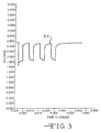
- Fig. 2 is a graph showing an illustrative discharge curve 12 as the voltage response of a cell that exhibits both forms of voltage delay.
- the initial drop in cell potential during the application of a short duration pulse reflects the resistance of the cell, i.e., the resistance due to the cathode-electrolyte interphase and the anode-electrolyte interphase and due to polarization.
- the resistance due to passivated films on the anode and/or cathode is negligible.
- the formation of a surface film is unavoidable for alkali metal, and in particular, lithium metal anodes, and for lithium intercalated carbon anodes, due to their relatively low potential and high reactivity towards organic electrolytes.
- the ideal anode surface film should be electrically insulating and ionically conducting.
- the second requirement is difficult to achieve.
- the resistance of these films is not negligible, and as a result, impedance builds up inside the cell due to this surface layer formation which often results in reduced discharge voltage and reduced cell capacity.
- the drop in potential between the background voltage and the lowest voltage under pulse discharge conditions, excluding voltage delay is an indication of the conductivity of the cell, i.e., the conductivity of the cathode, anode, electrolyte, and surface films, while the gradual decrease in cell potential during the application of the pulse train is due to the polarization of the electrodes and electrolyte.
- the present invention is directed to the provision of organic phosphate additives in the electrolyte of an alkali metal electrochemical cell to beneficially modify the anode surface film.
- the phosphate additives are defined herein as organic phosphate monoester, diester or triester compounds or phosphoric acid provided as a co-solvent with commonly used organic aprotic solvents.
- the organic phosphate additives are in a condensed phase which makes them easy to handle in electrolyte preparation.
- the phosphate additives interact with the alkali metal anode to form an ionically conductive surface protective layer thereon.
- the conductive surface layer improves the discharge performance of the alkali metal electrochemical cell and minimizes or even eliminates voltage delay in the high current pulse discharge of such cells.
- the object of the present invention is to improve the pulse discharge performance of an alkali metal electrochemical cell, and more particularly a primary lithium electrochemical cell, by the provision of at least-one of a family of phosphate additives, preferably a monoester, a diester or triester compound as a co-solvent in the cell's activating nonaqueous electrolyte solution.
- a family of phosphate additives preferably a monoester, a diester or triester compound as a co-solvent in the cell's activating nonaqueous electrolyte solution.
- the phosphate additives compete effectively with the other electrolyte cosolvents or the solute to react with the lithium anode.
- Lithium phosphate or the lithium salt of phosphate reduction products are believed to be the major reaction products.
- These lithium salts are believed to deposit on the anode surface to form an ionically conductive protective film thereon.
- the chemical composition and perhaps the morphology of the anode surface protective layer is changed, and this proves beneficial to the discharge characteristics of the cell.
- the present invention is directed to the introduction of at least one phosphate additive into the electrolyte of a lithium/silver vanadium oxide electrochemical cell for the purpose of reducing and/or eliminating voltage delay during pulse discharging applications.
- Alkali metal/transition metal oxide electrochemical systems are typically activated with an electrolyte comprising a relatively low viscosity solvent and a relatively high permittivity solvent.
- the solute of the electrolyte is an inorganic alkali metal salt wherein the alkali metal of the salt is the same as the alkali metal of the anode.
- the phosphate compound of the present invention is introduced into the electrolyte as an additive to interact with the alkali metal anode, and particularly with the lithium anode, to form an ionically conductive protective anode surface layer which improves the discharge performance of the cell, and minimizes or even eliminates voltage delay in current pulse discharge conditions. Therefore, the present invention is directed to a novel electrolyte solution provided in operative association with an electrochemical system incorporated into a defibrillator battery to minimize or even eliminate voltage delay under high current pulse discharge conditions.
- Fig. 1 is a graph showing an illustrative pulse discharge curve 10 of an exemplary electrochemical cell that does not exhibit voltage delay.
- Fig. 2 is a graph showing an illustrative pulse discharge curve 12 of an exemplary electrochemical cell that exhibits voltage delay.
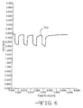
- Figs. 3 to 8 are graphs constructed from the pulse train waveforms of Li/SVO cells activated with a nonaqueous electrolyte having concentrations of dibenzyl phosphate ranging from 0.00M to 0.20M dissolved therein.
- pulse means a short burst of electrical current of a significantly greater amplitude than that of a prepulse current immediately prior to the pulse.
- a pulse train consists of at least two pulses of electrical current delivered in relatively short succession with or without open circuit rest between the pulses.
- the electrochemical cell of the present invention includes an anode selected from Groups IA, IIA or IIIB of the Periodic Table of Elements, including lithium, sodium, potassium, etc., and their alloys and intermetallic compounds including, for example Li-Si, Li-B and Li-Si-B alloys and intermetallic compounds.
- the preferred anode comprises lithium, and the more preferred anode comprises a lithium alloy, the preferred lithium alloy being a lithium-aluminum alloy. The greater the amount of aluminum present by weight in the alloy, however, the lower the energy density of the cell.
- the form of the anode may vary, but preferably the anode is a thin metal sheet or foil of the anode metal, pressed or rolled on a metallic anode current collector, i.e., preferably comprising nickel, to form an anode component.
- the anode component has an extended tab or lead of the same material as the anode current collector, i.e., preferably nickel, integrally formed therewith such as by. welding and contacted by a weld to a cell case of conductive metal in a case-negative electrical configuration.
- the anode may be formed in some other geometry, such as a bobbin shape, cylinder or pellet to allow an alternate low surface cell design.
- the cathode is preferably of a solid material and the electrochemical reaction at the cathode involves conversion of ions which migrate from the anode to the cathode in atomic or molecular forms.
- the solid cathode material may comprise a metal, a metal oxide, a mixed metal oxide, a metal sulfide or a carbonaceous compound, and combinations thereof.
- the metal oxide, the mixed metal oxide and the metal sulfide can be formed by the chemical addition, reaction, or otherwise intimate contact of various metal oxides, metal sulfides and/or metal elements, preferably during thermal treatment, sol-gel formation, chemical vapor deposition or hydrothermal synthesis in mixed states.
- the active materials thereby produced contain metals, oxides and sulfides of Groups IB, IIB, IIIB, IVB, VB, VIB, VIIB and VIII, which includes the noble metals and/or other oxide and sulfide compounds.
- One preferred mixed metal oxide has the general formula SM x V 2 O y wherein SM is a metal selected from Groups IB to VIIB and VIII of the Periodic Table of Elements, wherein x is about 0.30 to 2.0 and y is about 4.5 to 6.0 in the general formula.
- SVO silver vanadium oxide
- Another preferred composite cathode active material includes V 2 O z wherein z ⁇ 5 combined with Ag 2 O with the silver in either the silver(II), silver(I) or silver(0) oxidation state and CuO with the copper in either the copper(II), copper(I) or copper(0) oxidation state to provide the mixed metal oxide having the general formula Cu x Ag y V 2 O z , (CSVO).
- this composite cathode active material may be described as a metal oxide-metal oxide-metal oxide, a metal-metal oxide-metal oxide, or a metal-metal-metal oxide and the range of material compositions found for Cu x Ag y V 2 O z is preferably about 0.01 ⁇ x ⁇ 1.0, about 0.01 ⁇ y ⁇ 1.0 and about 5.01 ⁇ z ⁇ 6.5.
- Typical forms of CSVO are Cu 0.16 Ag 0.67 V 2 O z with z being about 5.5 and Cu 0.5 Ag 0.5 V 2 O z with z being about 5.75.
- the oxygen content is designated by z since the exact stoichiometric proportion of oxygen in CSVO can vary depending on whether the cathode material is prepared in an oxidizing atmosphere such as air or oxygen, or in an inert atmosphere such as argon, nitrogen and helium.
- an oxidizing atmosphere such as air or oxygen
- an inert atmosphere such as argon, nitrogen and helium.
- cathode active materials include manganese dioxide, lithium cobalt oxide, lithium nickel oxide, copper vanadium oxide, titanium disulfide, copper oxide, copper sulfide, iron sulfide, iron disulfide, and fluorinated carbon, and mixtures thereof.
- the cathode comprises from about 80 to about 99 weight percent of the cathode active material.
- Cathode active materials prepared as described above are preferably mixed with a binder material such as a powdered fluoro-polymer, more preferably powdered polytetrafluoroethylene or powdered polyvinylidene fluoride present at about 1 to about 5 weight percent of the cathode mixture. Further, up to about 10 weight percent of a conductive diluent is preferably added to the cathode mixture to improve conductivity. Suitable materials for this purpose include acetylene black, carbon black and/or graphite or a metallic powder such as powdered nickel, aluminum, titanium and stainless steel.
- the preferred cathode active mixture thus includes a powdered fluoro-polymer binder present at about 3 weight percent, a conductive diluent present at about 3 weight percent and about 94 weight percent of the cathode active material.
- the cathode active mixture may be in the form of one or more plates operatively associated with at least one or more plates of anode material, or in the form of a strip wound with a corresponding strip of anode material in a structure similar to a "jellyroll".
- the cathode is separated from the Group IA, IIA or IIIB anode material by a suitable separator material.
- the separator is of electrically insulative material, and the separator material also is chemically unreactive with the anode and cathode active materials and both chemically unreactive with and insoluble in the electrolyte.
- the separator material has a degree of porosity sufficient to allow flow therethrough of the electrolyte during the electrochemical reaction of the cell.
- Illustrative separator materials include woven and non-woven fabrics of polyolefinic fibers or fluoropolymeric fibers including polyvinylidene fluoride, polyethylenetetrafluoroethylene, and polyethylenechlorotrifluoroethylene laminated or superposed with a polyolefinic or a fluoropolymeric microporous film.
- Suitable microporous films include a polytetrafluoroethylene membrane commercially available under the designation ZITEX (Chemplast Inc.), polypropylene membrane commercially available under the designation CELGARD (Celanese Plastic Company, Inc.) and a membrane commercially available under the designation DEXIGLAS (C.H. Dexter, Div., Dexter Corp.).
- the separator may also be composed of non-woven glass, glass fiber materials and ceramic materials.
- the form of the separator typically is a sheet which is placed between the anode and cathode electrodes and in a manner preventing physical contact therebetween.
- Such is the case when the anode is folded in a serpentine-like structure with a plurality of cathode plates disposed intermediate the anode folds and received in a cell casing or when the electrode combination is rolled or otherwise formed into-a cylindrical "jellyroll" configuration.
- the electrochemical cell of the present invention further includes a nonaqueous, ionically conductive electrolyte operatively associated with the anode and the cathode electrodes.
- the electrolyte serves as a medium for migration of ions between the anode and the cathode during the electrochemical reactions of the cell and nonaqueous solvents suitable for the present invention are chosen so as to exhibit those physical properties necessary for ionic transport (low viscosity, low surface tension and wettability).
- Suitable nonaqueous solvents are comprised of an inorganic salt dissolved in a nonaqueous solvent and more preferably an alkali metal salt dissolved in a mixture of aprotic organic solvents comprising a low viscosity solvent including organic esters, ethers and dialkyl carbonates, and mixtures thereof, and a high permittivity solvent including cyclic carbonates, cyclic esters and cyclic amides, and mixtures thereof.
- Low viscosity solvents include tetrahydrofuran (THF), methyl acetate (MA), diglyme, triglyme, tetraglyme, 1,2-dimethoxyethane (DME), 1,2-diethoxyethane (DEE), 1-ethoxy, 2-methoxyethane (EME), dimethyl carbonate (DMC), diethyl carbonate (DEC), dipropyl carbonate (DPC), ethyl methyl carbonate (EMC), methyl propyl carbonate (MPC) and ethyl propyl carbonate (EPC), and mixtures thereof.
- THF tetrahydrofuran
- MA 1,2-dimethoxyethane
- DEE 1,2-diethoxyethane
- EME dimethyl carbonate
- DEC diethyl carbonate
- DPC dipropyl carbonate
- EMC ethyl methyl carbonate
- MPC methyl propyl carbonate
- EPC ethy
- High permittivity solvents include propylene carbonate (PC), ethylene carbonate (EC), butylene carbonate (BC), acetonitrile, dimethyl sulfoxide,- dimethyl formamide, dimethyl acetamide, ⁇ -butyrolactone (GBL) and N-methyl-pyrrolidinone (NMP), and mixtures thereof.
- PC propylene carbonate
- EC ethylene carbonate
- BC butylene carbonate
- acetonitrile dimethyl sulfoxide
- GBL ⁇ -butyrolactone
- NMP N-methyl-pyrrolidinone
- the preferred electrolyte comprises an inorganic alkali metal salt, and in the case of an anode comprising lithium, the alkali metal salt of the electrolyte is a lithium based salt.
- Known lithium salts that are useful as a vehicle for transport of alkali metal ions from the anode to the cathode include LiPF 6 , LiBF 4 , LiAsF 6 , LiSbF 6 , LiClO 4 , LiAlCl 4 , LiGaCl 4 -, LiC(SO 2 CF 3 ) 3 , LiN(SO 2 CF 3 ) 2 , LiSCN, LiO 3 SCF 2 CF 3 , LiC 6 F 5 SO 3 , LiO 2 CF 3 , LiSO 3 F, LiB(C 6 H 5 ) 4 and LiCF 3 SO 3 , and mixtures thereof.
- Suitable salt concentrations typically range between about 0.8 to 1.5 molar, and a preferred electrolyte for a lithium/transition metal oxide electrochemical cell includes LiAsF 6 or LiPF 6 dissolved in a 50:50 mixture, by volume, of PC and DME.
- At least one organic phosphate additive is provided as a co-solvent in the electrolyte solution of the previously described alkali metal electrochemical cell.
- dimethyl phosphate, diethyl phosphate, dipropyl phosphate, dibutyl phosphate, diphenyl phosphate, dibenzyl phosphate, diallyl phosphate, monomethyl phosphate, mono-ethyl phosphate, mono-propyl phosphate, mono-butyl phosphate, mono-phenyl phosphate, mono-benzyl phosphate and mixtures thereof are used as additives in the electrolyte.
- the anode is lithium metal and the cathode is preferably the transition mixed metal oxide AgV 2 O 5.5 (SVO).
- the preferred electrolyte is 1.0M to 1.2M LiAsF 6 dissolved in an aprotic solvent mixture comprising at least one of the above listed low viscosity solvents and at least one of the above listed high permittivity solvents.
- the preferred aprotic solvent mixture comprises a 50/50, by volume, mixture of propylene carbonate and dimethoxyethane.
- concentration of the above discussed phosphate additives according to the present invention should preferably be in the range of between about 0.001M to about 0.40M.
- an implantable cardiac defibrillator is a device that requires a power source for a generally medium rate, constant resistance load component provided by circuits performing such functions as, for example, the heart sensing and pacing functions. From time to time, the cardiac defibrillator may require a generally high rate, pulse discharge load component that occurs, for example, during charging of a capacitor in the defibrillator for the purpose of delivering an electrical shock to the heart to treat tachyarrhythmias, the irregular, rapid heart beats that can be fatal if left uncorrected. Reduction and even elimination of voltage delay during a current pulse application is important for proper device operation and extended device life.
- the assembly of the cell described herein is preferably in the form of a wound element cell. That is, the fabricated cathode, anode and separator are wound together in a "jellyroll" type configuration or “wound element cell stack" such that the anode is on the outside of the roll to make electrical contact with the cell case in a case-negative configuration.
- the wound cell stack is inserted into a metallic case of a suitable size dimension.
- the metallic case may comprise materials such as stainless steel, mild steel, nickel-plated mild steel, titanium, tantalum or aluminum, but not limited thereto, so long as the metallic material is compatible for use with components of the cell.
- the cell header comprises a metallic disc-shaped body with a first-hole to accommodate a glass-to-metal seal/terminal pin feedthrough and a second hole for electrolyte filling.
- the glass used is of a corrosion resistant type having up to about 50% by weight silicon such as CABAL 12, TA 23 or FUSITE 425 or FUSITE 435.
- the positive terminal pin feedthrough preferably comprises titanium although molybdenum, aluminum, nickel alloy, or stainless steel can also be used.
- the cell header comprises elements having compatibility with the other components of the electrochemical cell and is resistant to corrosion.
- the cathode lead is welded to the positive terminal pin in the glass-to-metal seal and the header is welded to the case containing the electrode stack.
- the cell is thereafter filled with the electrolyte solution comprising at least one of the phosphate additives described hereinabove and hermetically sealed such as by close-welding a stainless steel ball over the fill hole, but not limited thereto.
- the above assembly describes a case-negative cell, which is the preferred construction of the exemplary cell of the present invention.
- the exemplary electrochemical system of the present invention can also be constructed in a case-positive configuration.
- Lithium anode material was pressed on nickel current collector screen and silver vanadium oxide cathode material was pressed on titanium current collector screen.
- a prismatic cell stack assembly configuration with two layers of microporous membrane propylene separator sandwiched between the anode and cathode was prepared.
- the electrode assembly was then hermetically sealed in a stainless steel casing in a case-negative configuration.
- Three cells were activated with the standard electrolyte consisting of 1.0M LiAsF 6 dissolved in a 50:50, by volume, mixture of PC and DME without an organic phosphate additive (Group 1).
- DBP dibenzyl phosphate
- a constant resistance load of 3.57 k ⁇ was applied to all of the cells for 21 hours during an initial predischarge burn-in period.
- the predischarge period is referred to as burn-in and depleted the cells of approximately 1% of their theoretical capacity.
- the cells were subjected to acceptance pulse testing consisting of four 10 second pulses (23.2 mA/cm 2 ) with a 15 second rest between each pulse.
- the average discharge readings for the pre-pulse potentials, voltage delay and pulse minimum potentials during acceptance pulse testing for these pulse trains are summarized in Table 2.
- pulse train 4 only the group 1 cells exhibited voltage delay while none of the other cells with the DBP additive exhibited voltage delay. In pulse train 4, all of the cells having the DBP additive exhibited greater pulse 1 minimum potentials than those of the cells without the DBP additive. However, the group 1 cells devoid of the DBP additive still had the greatest pulse 4 minimum potentials.
- Figs. 6 to 8 wherein curve 30 was constructed from the pulse train 5 waveform of a representative group 4 cell activated with the electrolyte having the DBP additive at a concentration of 0.05M, curve 32 in Fig. 7 was constructed from the pulse train 5 waveform of the representative 5 cell activated with the electrolyte having the DBP additive at a concentration of 0.10M and curve 34 in Fig. 8 was constructed from the pulse train 5 waveform of a representative group 6 cell activated with the electrolyte having the DBP additive at a concentration of 0.20M. Moreover, among the groups 1 to 3 cells, the greater the DBP concentration, the lower the voltage delay. In pulse train 5, all of the cells having the DBP additive exhibited higher pulse 1 and pulse 4 minimum potentials than those of the group 1 cells. The best performance was observed for the group 4 cells with 0.05M DBP.
- pulse train 6 only the group 3 cells exhibited some voltage delay while all other groups of cells exhibited no voltage delay. Also, in pulse train 6, except for the group 2 and 3 cells with relatively low DBP concentrations, all of the other cells with relatively high DBP concentrations presented greater pulse 1 minimum potentials than that of the group 1 control cells. Furthermore, in pulse train 6, all of the cells with the DBP additive exhibited greater pulse 4 minimum potentials than that of the group 1 control cells. The group 4 cells exhibited the best overall performance.
- Eighteen cells were constructed in a similar manner as those described in Example I except for the phosphate additive. Specifically, three of the cells were activated with the standard electrolyte consisting of 1.0M LiAsF 6 dissolved in a 50:50, by volume, mixture of PC and DME without an organic phosphate additive (Group 1). Fifteen cells (three cells per group) were activated with the same electrolyte used to activate the Group 1 cells and further containing 0.005M, 0.01M, 0.05M, 0.10M, or 0.20M of trimethyl phosphate (TMP).
- TMP trimethyl phosphate
- Example 9 In a similar manner as the cells discharged in Example I, a constant resistance load of 3.57 k ⁇ was applied to all of the cells for 21 hours during an initial predischarge burn-in period. Following burn-in, the cells were subjected to acceptance pulse testing consisting of four 10 second pulses (23.2 mA/cm 2 ) with a 15 second rest between each pulse. The average discharge readings for the pre-pulse potentials, voltage delay and pulse minimum potentials during acceptance pulse testing for these pulse trains are summarized in Table 9.
- Eighteen cells were constructed in a similar manner as those described in Example I except for the phosphate additive. Specifically, three of the cells were activated with the standard electrolyte consisting of 1.0M LiAsF 6 dissolved in a 50:50, by volume, mixture of PC and DME without an organic phosphate additive (Group 1). Fifteen cells (three cells per group) were activated with the same electrolyte used to activate the Group 1 cells and further containing 0.005M, 0.01M, 0.05M, 0.10M, or 0.20M of triphenyl phosphate (TPP).
- TPP triphenyl phosphate
- Example 17 In a similar manner as the cells discharged in Example I, a constant resistance load of 3.57 k ⁇ was applied to all of the cells for 21 hours during an initial predischarge burn-in period. Following burn-in, the cells were subjected to acceptance pulse testing consisting of four 10 second pulses (23.2 mA/cm 2 ) with a 15 second rest between each pulse. The averaged discharge readings for the pre-pulse potentials, voltage delay and pulse minimum potentials during acceptance pulse testing for these pulse trains are summarized in Table 17.
- Example I demonstrates that if the O-R bond is activated by either R equal to hydrogen (acidic proton) or R equal to benzyl or allyl types of organic groups, an electrically insulating and ionically conducting anode surface film is obtain.
- R methyl or phenyl
- the reduction of the phosphate additive by the lithium anode does not result in the O-R bond cleavage to form an O-Li salt product.
- the R group in the phosphate additive is hydrogen (acidic proton), it will react with lithium metal to form an O-Li bond directly.
- the concentration limit for the phosphate additive is preferably about 0.001M to about 0.40M.
- the beneficial effect of the phosphate additive will not be apparent if the additive concentration is less than about 0.001M. On the other hand, if the additive concentration is greater than about 0.40M, the beneficial effect of the additive will be cancelled by the detrimental effect of higher internal cell resistance due to the thicker anode surface film formation and lower electrolyte conductivity.
- the existence of voltage delay is due to the formation of an anode surface passivation layer that is ionically less conductive than either the anode material itself or the electrolyte solution.
- This surface film is ionically more conductive than the film formed in the absence of the additives and it is responsible for the increased cell performance, especially during pulse discharge applications.
- diminished voltage delay results when an alkali metal/transition metal oxide couple activated with a nonaquous organic solvent having a phosphate additive dissolved therein according to the present invention is subjected to a pulse discharge application. This is particularly important in implantable medical devices powered by a cell according to the present invention.
Description
- The present invention generally relates to an alkali metal electrochemical cell, and more particularly, to an alkali metal cell suitable for current pulse discharge applications with reduced or no appreciable voltage delay. Still more particularly, the present invention relates to a lithium electrochemical cell activated with an electrolyte having an additive for the purpose of reducing and/or eliminating voltage delay under current pulse discharge applications. Voltage delay is a phenomenon typically exhibited in an alkali metal/transition metal oxide cell, and particularly, a lithium/silver vanadium oxide cell, that has been depleted of 40% to 70% of its capacity and is subjected to current pulse discharge applications. According to the present invention, the preferred additive to the activating electrolyte for such a chemistry is a phosphate compound.
- The voltage response of a cell which does not exhibit voltage delay during the application of a short duration pulse or pulse train has distinct features. First, the cell potential decreases throughout the application of the pulse until it reaches a minimum at the end of the pulse, and second, the minimum potential of the first pulse in a series of pulses is higher than the minimum potential of the last pulse. Fig. 1 is a graph showing an
illustrative discharge curve 10 as a typical or "ideal" response of a cell during the application of a series of pulses as a pulse train that does not exhibit voltage delay. - On the other hand, the voltage response of a cell which exhibits voltage delay during the application of a short duration pulse or during a pulse train can take one or both of two forms. One form is that the leading edge potential of the first pulse is lower than the end edge potential of the first pulse. In other words, the voltage of the cell at the instant the first pulse is applied is lower than the voltage of the cell immediately before the first pulse is removed. The second form of voltage delay is that the minimum potential of the first pulse is lower than the minimum potential of the last pulse when a series of pulses have been applied. Fig. 2 is a graph showing an
illustrative discharge curve 12 as the voltage response of a cell that exhibits both forms of voltage delay. - The initial drop in cell potential during the application of a short duration pulse reflects the resistance of the cell, i.e., the resistance due to the cathode-electrolyte interphase and the anode-electrolyte interphase and due to polarization. In the absence of voltage delay, the resistance due to passivated films on the anode and/or cathode is negligible. However, the formation of a surface film is unavoidable for alkali metal, and in particular, lithium metal anodes, and for lithium intercalated carbon anodes, due to their relatively low potential and high reactivity towards organic electrolytes. Thus, the ideal anode surface film should be electrically insulating and ionically conducting. While most alkali metal, and in particular, lithium electrochemical systems meet the first requirement, the second requirement is difficult to achieve. In the event of voltage delay, the resistance of these films is not negligible, and as a result, impedance builds up inside the cell due to this surface layer formation which often results in reduced discharge voltage and reduced cell capacity. In other words, the drop in potential between the background voltage and the lowest voltage under pulse discharge conditions, excluding voltage delay, is an indication of the conductivity of the cell, i.e., the conductivity of the cathode, anode, electrolyte, and surface films, while the gradual decrease in cell potential during the application of the pulse train is due to the polarization of the electrodes and electrolyte.
- Thus, the existence of voltage delay is an undesirable characteristic of alkali metal/mixed metal oxide cells subjected to current pulse discharge conditions in terms of its influence on devices such as medical devices including implantable pacemakers and cardiac defibrillators. Voltage delay is undesirable because it limits the effectiveness and even the proper functioning of both the cell and the associated electrically powered device under current pulse discharge conditions.
- One of the known solutions to the above problem is to saturate the electrolyte solution with carbon dioxide CO2. Cycling efficiency is-improved dramatically in secondary cell systems having a lithium anode activated with CO2 saturated electrolytes (V.R. Koch and S.B. Brummer, Electrochimica Acta, 1978, 23, 55-62; U.S. Patent No. 4,853,304 to Ebner et al.; D. Aurbach, Y. Gofer, M. Ben-Zion and P. Aped, J. Electroanal. Chem. 1992, 339, 451-471). U.S. Patent No. 5,569,558 to Takeuchi et al. relates to the provision of a CO2 saturated electrolyte for alleviating the presence of voltage delay in primary cells having a mixed transition metal oxide cathode such as lithium/silver vanadium oxide cells. The same effect is also known for lithium intercalated carbon anode secondary batteries (D. Aurbach, Y. Ein-Eli, O. Chusid, Y. Carmeli, M. Babai and H. Yamin, J. Electrochem. Soc. 1994, 141, 603-611). Sulfur dioxide (SO2) has also been reported to be another additive that improves charge-discharge cycling in rechargeable lithium ion cells (Y. Ein-Eli, S.R. Thomas and V.R. Koch, J. Electrochem. Soc. 1996, 143, L195-L197).
- In spite of the success of CO2 and SO2 in improving cell discharge characteristics, their use has been limited. One problem associated with both CO2 and SO2 as electrolyte additives is that they are in a gaseous state at room temperature, and are thus difficult to handle. Also, it is difficult to control the dissolved concentration of CO2. Best results are achieved at pressures, of up to 50 psig., which further detracts from the practicality of this additive.
- Instead of carbon dioxide and sulfur dioxide, the present invention is directed to the provision of organic phosphate additives in the electrolyte of an alkali metal electrochemical cell to beneficially modify the anode surface film. The phosphate additives are defined herein as organic phosphate monoester, diester or triester compounds or phosphoric acid provided as a co-solvent with commonly used organic aprotic solvents. The organic phosphate additives are in a condensed phase which makes them easy to handle in electrolyte preparation. When used as a co-solvent in an activating electrolyte, the phosphate additives interact with the alkali metal anode to form an ionically conductive surface protective layer thereon. The conductive surface layer improves the discharge performance of the alkali metal electrochemical cell and minimizes or even eliminates voltage delay in the high current pulse discharge of such cells.
- The object of the present invention is to improve the pulse discharge performance of an alkali metal electrochemical cell, and more particularly a primary lithium electrochemical cell, by the provision of at least-one of a family of phosphate additives, preferably a monoester, a diester or triester compound as a co-solvent in the cell's activating nonaqueous electrolyte solution. In particular the present invention provides an electrochemical cell which is dischargeable to deliver a current pulse while exhibiting reduced voltage delay, which comprises a)an anode comprising an alkali metal; b) a solid cathode of electrically conductive material; and c) a nonaqueous electrolyte activating the anode and the cathode, the nonaqueous electrolyte comprising: i) a first solvent selected from the group consisting of an ester, an ether, a dialkyl carbonate, and mixtures thereof; ii) a second solvent selected from the group consisting of a cyclic carbonate, a cyclic ester, a cyclic amide, and mixtures thereof; iii) a phosphate additive having the formula (R2O)P(=O) (OR2) (OR3) wherein R1, R2 and R3 can be a hydrogen atom or a saturated or unsaturated organic group containing 1 to 13 carbon atoms and at least one of R1, R2 and R3 is a hydrogen atom; and iv) an alkali metal salt dissolved therein, wherein the alkali metal of the salt is similar to the alkali metal comprising the anode, and wherein the activated anode and cathode provide the electrochemical cell dischargeable to deliver at least one current pulse of a short duration burst of electrical current of a significantly greater amplitude than that of a prepulse current immediately prior to the pulse such that the pulse one end potential minus the pulse one minimum potential is less than about 0.2 volts. Due to the high reduction potentials of the phosphate group vs. lithium, the phosphate additives compete effectively with the other electrolyte cosolvents or the solute to react with the lithium anode. Lithium phosphate or the lithium salt of phosphate reduction products are believed to be the major reaction products. These lithium salts are believed to deposit on the anode surface to form an ionically conductive protective film thereon. As a consequence, the chemical composition and perhaps the morphology of the anode surface protective layer is changed, and this proves beneficial to the discharge characteristics of the cell.
- The thusly fabricated cell exhibits reduced or no appreciable voltage delay under current pulse discharge usage, which is an unexpected result. More particularly, the present invention is directed to the introduction of at least one phosphate additive into the electrolyte of a lithium/silver vanadium oxide electrochemical cell for the purpose of reducing and/or eliminating voltage delay during pulse discharging applications. Alkali metal/transition metal oxide electrochemical systems are typically activated with an electrolyte comprising a relatively low viscosity solvent and a relatively high permittivity solvent. The solute of the electrolyte is an inorganic alkali metal salt wherein the alkali metal of the salt is the same as the alkali metal of the anode. The phosphate compound of the present invention is introduced into the electrolyte as an additive to interact with the alkali metal anode, and particularly with the lithium anode, to form an ionically conductive protective anode surface layer which improves the discharge performance of the cell, and minimizes or even eliminates voltage delay in current pulse discharge conditions. Therefore, the present invention is directed to a novel electrolyte solution provided in operative association with an electrochemical system incorporated into a defibrillator battery to minimize or even eliminate voltage delay under high current pulse discharge conditions.
- These and other objects of the present invention will become increasingly more apparent to those skilled in the art by reference to the following description and to the appended drawings.
- Fig. 1 is a graph showing an illustrative
pulse discharge curve 10 of an exemplary electrochemical cell that does not exhibit voltage delay. - Fig. 2 is a graph showing an illustrative
pulse discharge curve 12 of an exemplary electrochemical cell that exhibits voltage delay. - Figs. 3 to 8 are graphs constructed from the pulse train waveforms of Li/SVO cells activated with a nonaqueous electrolyte having concentrations of dibenzyl phosphate ranging from 0.00M to 0.20M dissolved therein.
- As used herein, the term "pulse" means a short burst of electrical current of a significantly greater amplitude than that of a prepulse current immediately prior to the pulse. A pulse train consists of at least two pulses of electrical current delivered in relatively short succession with or without open circuit rest between the pulses.
- The electrochemical cell of the present invention includes an anode selected from Groups IA, IIA or IIIB of the Periodic Table of Elements, including lithium, sodium, potassium, etc., and their alloys and intermetallic compounds including, for example Li-Si, Li-B and Li-Si-B alloys and intermetallic compounds. The preferred anode comprises lithium, and the more preferred anode comprises a lithium alloy, the preferred lithium alloy being a lithium-aluminum alloy. The greater the amount of aluminum present by weight in the alloy, however, the lower the energy density of the cell.
- The form of the anode may vary, but preferably the anode is a thin metal sheet or foil of the anode metal, pressed or rolled on a metallic anode current collector, i.e., preferably comprising nickel, to form an anode component. In the exemplary cell of the present invention, the anode component has an extended tab or lead of the same material as the anode current collector, i.e., preferably nickel, integrally formed therewith such as by. welding and contacted by a weld to a cell case of conductive metal in a case-negative electrical configuration. Alternatively, the anode may be formed in some other geometry, such as a bobbin shape, cylinder or pellet to allow an alternate low surface cell design.
- The cathode is preferably of a solid material and the electrochemical reaction at the cathode involves conversion of ions which migrate from the anode to the cathode in atomic or molecular forms. The solid cathode material may comprise a metal, a metal oxide, a mixed metal oxide, a metal sulfide or a carbonaceous compound, and combinations thereof. The metal oxide, the mixed metal oxide and the metal sulfide can be formed by the chemical addition, reaction, or otherwise intimate contact of various metal oxides, metal sulfides and/or metal elements, preferably during thermal treatment, sol-gel formation, chemical vapor deposition or hydrothermal synthesis in mixed states. The active materials thereby produced contain metals, oxides and sulfides of Groups IB, IIB, IIIB, IVB, VB, VIB, VIIB and VIII, which includes the noble metals and/or other oxide and sulfide compounds.
- One preferred mixed metal oxide has the general formula SMxV2Oy wherein SM is a metal selected from Groups IB to VIIB and VIII of the Periodic Table of Elements, wherein x is about 0.30 to 2.0 and y is about 4.5 to 6.0 in the general formula. By way of illustration, and in no way intended to be limiting, one exemplary cathode active material comprises silver vanadium oxide (SVO) having the general formula AgxV2Oy in any one of its many phases, i.e., β-phase silver vanadium oxide having in the general formula x = 0.35 and y = 5.8, γ-phase silver vanadium oxide having in the general formula x = 0.74 and y = 5.37 and ε-phase silver vanadium oxide having in the general formula x = 1.0 and y = 5.5, and combination and mixtures of phases thereof. For a more detailed description of such a cathode active material reference is made to U.S. Patent No. 4,310,609 to Liang et al., which is assigned to the assignee of the present invention and incorporated herein by reference.
- Another preferred composite cathode active material includes V2Oz wherein z ≤ 5 combined with Ag2O with the silver in either the silver(II), silver(I) or silver(0) oxidation state and CuO with the copper in either the copper(II), copper(I) or copper(0) oxidation state to provide the mixed metal oxide having the general formula CuxAgyV2Oz, (CSVO). Thus, this composite cathode active material may be described as a metal oxide-metal oxide-metal oxide, a metal-metal oxide-metal oxide, or a metal-metal-metal oxide and the range of material compositions found for CuxAgyV2Oz is preferably about 0.01 ≤ x ≤ 1.0, about 0.01 ≤ y ≤ 1.0 and about 5.01 ≤ z ≤ 6.5. Typical forms of CSVO are Cu0.16Ag0.67V2Oz with z being about 5.5 and Cu0.5Ag0.5V2Oz with z being about 5.75. The oxygen content is designated by z since the exact stoichiometric proportion of oxygen in CSVO can vary depending on whether the cathode material is prepared in an oxidizing atmosphere such as air or oxygen, or in an inert atmosphere such as argon, nitrogen and helium. For a more detailed description of this cathode active material reference is made to U.S. Patent Nos. 5,472,810 to Takeuchi et al. and 5,516,340 to Takeuchi et al., both of which are assigned to the assignee of the present invention and incorporated herein by reference.
- Additional cathode active materials include manganese dioxide, lithium cobalt oxide, lithium nickel oxide, copper vanadium oxide, titanium disulfide, copper oxide, copper sulfide, iron sulfide, iron disulfide, and fluorinated carbon, and mixtures thereof. Preferably, the cathode comprises from about 80 to about 99 weight percent of the cathode active material.
- Cathode active materials prepared as described above are preferably mixed with a binder material such as a powdered fluoro-polymer, more preferably powdered polytetrafluoroethylene or powdered polyvinylidene fluoride present at about 1 to about 5 weight percent of the cathode mixture. Further, up to about 10 weight percent of a conductive diluent is preferably added to the cathode mixture to improve conductivity. Suitable materials for this purpose include acetylene black, carbon black and/or graphite or a metallic powder such as powdered nickel, aluminum, titanium and stainless steel. The preferred cathode active mixture thus includes a powdered fluoro-polymer binder present at about 3 weight percent, a conductive diluent present at about 3 weight percent and about 94 weight percent of the cathode active material. The cathode active mixture may be in the form of one or more plates operatively associated with at least one or more plates of anode material, or in the form of a strip wound with a corresponding strip of anode material in a structure similar to a "jellyroll".
- In order to prevent internal short circuit conditions, the cathode is separated from the Group IA, IIA or IIIB anode material by a suitable separator material. The separator is of electrically insulative material, and the separator material also is chemically unreactive with the anode and cathode active materials and both chemically unreactive with and insoluble in the electrolyte. In addition, the separator material has a degree of porosity sufficient to allow flow therethrough of the electrolyte during the electrochemical reaction of the cell. Illustrative separator materials include woven and non-woven fabrics of polyolefinic fibers or fluoropolymeric fibers including polyvinylidene fluoride, polyethylenetetrafluoroethylene, and polyethylenechlorotrifluoroethylene laminated or superposed with a polyolefinic or a fluoropolymeric microporous film. Suitable microporous films include a polytetrafluoroethylene membrane commercially available under the designation ZITEX (Chemplast Inc.), polypropylene membrane commercially available under the designation CELGARD (Celanese Plastic Company, Inc.) and a membrane commercially available under the designation DEXIGLAS (C.H. Dexter, Div., Dexter Corp.). The separator may also be composed of non-woven glass, glass fiber materials and ceramic materials.
- The form of the separator typically is a sheet which is placed between the anode and cathode electrodes and in a manner preventing physical contact therebetween. Such is the case when the anode is folded in a serpentine-like structure with a plurality of cathode plates disposed intermediate the anode folds and received in a cell casing or when the electrode combination is rolled or otherwise formed into-a cylindrical "jellyroll" configuration.
- The electrochemical cell of the present invention further includes a nonaqueous, ionically conductive electrolyte operatively associated with the anode and the cathode electrodes. The electrolyte serves as a medium for migration of ions between the anode and the cathode during the electrochemical reactions of the cell and nonaqueous solvents suitable for the present invention are chosen so as to exhibit those physical properties necessary for ionic transport (low viscosity, low surface tension and wettability). Suitable nonaqueous solvents are comprised of an inorganic salt dissolved in a nonaqueous solvent and more preferably an alkali metal salt dissolved in a mixture of aprotic organic solvents comprising a low viscosity solvent including organic esters, ethers and dialkyl carbonates, and mixtures thereof, and a high permittivity solvent including cyclic carbonates, cyclic esters and cyclic amides, and mixtures thereof. Low viscosity solvents include tetrahydrofuran (THF), methyl acetate (MA), diglyme, triglyme, tetraglyme, 1,2-dimethoxyethane (DME), 1,2-diethoxyethane (DEE), 1-ethoxy, 2-methoxyethane (EME), dimethyl carbonate (DMC), diethyl carbonate (DEC), dipropyl carbonate (DPC), ethyl methyl carbonate (EMC), methyl propyl carbonate (MPC) and ethyl propyl carbonate (EPC), and mixtures thereof. High permittivity solvents include propylene carbonate (PC), ethylene carbonate (EC), butylene carbonate (BC), acetonitrile, dimethyl sulfoxide,- dimethyl formamide, dimethyl acetamide, γ-butyrolactone (GBL) and N-methyl-pyrrolidinone (NMP), and mixtures thereof.
- The preferred electrolyte comprises an inorganic alkali metal salt, and in the case of an anode comprising lithium, the alkali metal salt of the electrolyte is a lithium based salt. Known lithium salts that are useful as a vehicle for transport of alkali metal ions from the anode to the cathode include LiPF6, LiBF4, LiAsF6, LiSbF6, LiClO4, LiAlCl4, LiGaCl4-, LiC(SO2CF3)3, LiN(SO2CF3)2, LiSCN, LiO3SCF2CF3, LiC6F5SO3, LiO2CF3, LiSO3F, LiB(C6H5)4 and LiCF3SO3, and mixtures thereof. Suitable salt concentrations typically range between about 0.8 to 1.5 molar, and a preferred electrolyte for a lithium/transition metal oxide electrochemical cell includes LiAsF6 or LiPF6 dissolved in a 50:50 mixture, by volume, of PC and DME.
- In accordance with the present invention, at least one organic phosphate additive is provided as a co-solvent in the electrolyte solution of the previously described alkali metal electrochemical cell. The phosphate additive is preferably an alkyl phosphate compound having the general formula (R1O) P(=O) (OR2) (OR3) wherein R1, R2 and R3 are the same or different, and they can be a hydrogen atom or a saturated or unsaturated organic group containing 1 to 13 carbon atoms. If R1, R2 and R3 are not hydrogen, at least one of them is CR4R5R6 where at least R4 is an aromatic substituent or an unsaturated organic or inorganic group. The greatest effect is found when dimethyl phosphate, diethyl phosphate, dipropyl phosphate, dibutyl phosphate, diphenyl phosphate, dibenzyl phosphate, diallyl phosphate, monomethyl phosphate, mono-ethyl phosphate, mono-propyl phosphate, mono-butyl phosphate, mono-phenyl phosphate, mono-benzyl phosphate and mixtures thereof are used as additives in the electrolyte.
- The above described compounds are only intended to be exemplary of those that are useful with the present invention, and are not to be construed as limiting. Those skilled in the art will readily recognize phosphate compounds which come under the purview of the general formula set forth above and which will be useful as additives for the electrolyte to reduce voltage delay according to the present invention.
- While not intending to be bound by any particular mechanism, it is believed that due to the presence of the P=O bond-in the -OP(=O)O2- functional group, the bond between oxygen and at least one of the group R1, R2 and R3 is severed and the phosphate intermediate is able to compete effectively with the other electrolyte solvents or solutes to react with lithium and form a phosphate salt, i.e., lithium phosphate, or the lithium salt of a phosphate reduction product on the surface of the anode. The resulting salt is ionically more conductive than lithium oxide which may form on the anode in the absence of the organic phosphate additive. As a consequence, the chemical composition and perhaps the morphology of the anode surface protective layer is believed to be changed with concomitant benefits to the cell's discharge characteristics.
- In the present invention, the anode is lithium metal and the cathode is preferably the transition mixed metal oxide AgV2O5.5 (SVO). The preferred electrolyte is 1.0M to 1.2M LiAsF6 dissolved in an aprotic solvent mixture comprising at least one of the above listed low viscosity solvents and at least one of the above listed high permittivity solvents. The preferred aprotic solvent mixture comprises a 50/50, by volume, mixture of propylene carbonate and dimethoxyethane. The concentration of the above discussed phosphate additives according to the present invention should preferably be in the range of between about 0.001M to about 0.40M. The positive effects of these additives in reducing voltage delay in a pulse discharging alkali metal cell have been achieved both at room temperature as well as at temperatures up to about 37°C. This makes the novel electrolyte solution of the present invention particularly useful for activating an alkali metal/transition metal oxide cell incorporated into an implantable medical device such as a cardiac defibrillator to minimize or even eliminate voltage delay under high current pulse discharge conditions.
- As is well known by those skilled in the art, an implantable cardiac defibrillator is a device that requires a power source for a generally medium rate, constant resistance load component provided by circuits performing such functions as, for example, the heart sensing and pacing functions. From time to time, the cardiac defibrillator may require a generally high rate, pulse discharge load component that occurs, for example, during charging of a capacitor in the defibrillator for the purpose of delivering an electrical shock to the heart to treat tachyarrhythmias, the irregular, rapid heart beats that can be fatal if left uncorrected. Reduction and even elimination of voltage delay during a current pulse application is important for proper device operation and extended device life.
- The assembly of the cell described herein is preferably in the form of a wound element cell. That is, the fabricated cathode, anode and separator are wound together in a "jellyroll" type configuration or "wound element cell stack" such that the anode is on the outside of the roll to make electrical contact with the cell case in a case-negative configuration. Using suitable top and bottom insulators, the wound cell stack is inserted into a metallic case of a suitable size dimension. The metallic case may comprise materials such as stainless steel, mild steel, nickel-plated mild steel, titanium, tantalum or aluminum, but not limited thereto, so long as the metallic material is compatible for use with components of the cell.
- The cell header comprises a metallic disc-shaped body with a first-hole to accommodate a glass-to-metal seal/terminal pin feedthrough and a second hole for electrolyte filling. The glass used is of a corrosion resistant type having up to about 50% by weight silicon such as
CABAL 12, TA 23 or FUSITE 425 or FUSITE 435. The positive terminal pin feedthrough preferably comprises titanium although molybdenum, aluminum, nickel alloy, or stainless steel can also be used. The cell header comprises elements having compatibility with the other components of the electrochemical cell and is resistant to corrosion. The cathode lead is welded to the positive terminal pin in the glass-to-metal seal and the header is welded to the case containing the electrode stack. The cell is thereafter filled with the electrolyte solution comprising at least one of the phosphate additives described hereinabove and hermetically sealed such as by close-welding a stainless steel ball over the fill hole, but not limited thereto. - The above assembly describes a case-negative cell, which is the preferred construction of the exemplary cell of the present invention. As is well known to those skilled in the art, the exemplary electrochemical system of the present invention can also be constructed in a case-positive configuration.
- The following examples describe the manner and process of an electrochemical cell according to the present invention, and set forth the best mode contemplated by the inventors of carrying out the invention, but are not construed as limiting.
- Lithium anode material was pressed on nickel current collector screen and silver vanadium oxide cathode material was pressed on titanium current collector screen. A prismatic cell stack assembly configuration with two layers of microporous membrane propylene separator sandwiched between the anode and cathode was prepared. The electrode assembly was then hermetically sealed in a stainless steel casing in a case-negative configuration. Three cells were activated with the standard electrolyte consisting of 1.0M LiAsF6 dissolved in a 50:50, by volume, mixture of PC and DME without an organic phosphate additive (Group 1). Fifteen cells (three cells per group) were activated with the same electrolyte used to activate the Group 1 cells and further containing 0.005M, 0.01M, 0.05M, 0.10M, or 0.20M of dibenzyl phosphate (DBP), as set forth in Table 1.
Cell Construction Group [LiAsF6] PC:DME [DBP] 1 1.0M 50:50 0.00M 2 1.0M 50:50 0.005M 3 1.0M 50:50 0.01M 4 1.0M 50:50 0.05M 5 1.0M 50:50 0.10M 6 1.0M 50:50 0.20M - A constant resistance load of 3.57 kΩ was applied to all of the cells for 21 hours during an initial predischarge burn-in period. The predischarge period is referred to as burn-in and depleted the cells of approximately 1% of their theoretical capacity. Following burn-in, the cells were subjected to acceptance pulse testing consisting of four 10 second pulses (23.2 mA/cm2) with a 15 second rest between each pulse. The average discharge readings for the pre-pulse potentials, voltage delay and pulse minimum potentials during acceptance pulse testing for these pulse trains are summarized in Table 2.
Acceptance Pulse Train Voltages (average) Group [DBP] Ppre1 V-Delay P1min P4min 1 0.00M 3.263 0.272 2.284 2.503 2 0.005M 3.267 0.242 2.329 2.517 3 0.01M 3.266 0.275 2.297 2.520 4 0.05M 3.265 0.388 2.135 2.479 5 0.10M 3.273 0.481 1.981 2.427 6 0.20M 3.282 0.438 1.965 2.383 - Following acceptance pulse testing, all of the cells were discharged under loads of 9.53 kohms with superimposed pulse trains applied every 39 days. The pulse trains consisted of four 10 second pulses (23.2 mA/cm2) with 15 seconds rest between each pulse. The average discharge readings for the pre-pulse potentials, voltage delay and pulse minimum potentials for pulse trains 1 to 6 are summarized in Tables 3 to 8, respectively.
Pulse Train 1 Voltages (average) Group [DBP] Ppre1 V-Delay P1min P4min 1 0.00M 3.224 0.000 2.629 2.507 2 0.005M 3.224 0.000 2.625 2.516 3 0.01M 3.224 0.000 2.624 2.513 4 0.05M 3.222 0.000 2.593 2.470 5 0.10M 3.221 0.000 2.577 2.442 6 0.20M 3.223 0.001 2.554 2.404 Pulse Train 2 Voltages (average) Group [DBP] Ppre1 V-Delay P1min P4min 1 0.00M 3.165 0.001 2.558 2.416 2 0.005M 3.164 0.000 2.538 2.407 3 0.01M 3.164 0.001 2.524 2.392 4. 0.05M 3.165 0.001 2.503 2.368 5 0.10M 3.162 0.001 2.490 2.350 6 0.20M 3.162 0.000 2.490 2.332 Pulse Train 3 Voltages (average) Group [DBP] Ppre1 V-Delay P1min P4min 1 0.00M 2.895 0.000 2.374 2.269 2 0.005M 2.882 0.000 2.357 2.259 3 0.01M 2.882 0.000 2.343 2.249 4 0.05M 2.891 0.000 2.327 2.224 5 0.10M 2.882 0.000 2.305 2.202 6 0.20M 2.889 0.000 2.305 2.189 Pulse Train 4 Voltages (average) Group [DBP] Ppre1 V-Delay P1min P4min 1 0.00M 2.620 0.053 2.116 2.139 2 0.005M 2.601 0.000 2.174 2.134 3 0.01M 2.600 0.000 2.174 2.127 4 0.05M 2.612 0.000 2.157 2.095 5 0.10M 2.603 0.001 2.133 2.069 6 0.20M 2.614 0.002 2.129 2.044 Pulse Train 5 Voltages (average) Group [DBP] Ppre1 V-Delay P1min P4min 1 0.00M 2.532 0.167 1.680 1.858 2 0.005M 2.528 0.150 1.766 1.901 3 0.01M 2.527 0.103 1.840 1.914 4 0.05M 2.530 0.000 2.038 1.970 5 0.10M 2.529 0.000 2.020 1.936 6 0.20M 2.532 0.000 2.025 1.938 Pulse Train 6 Voltages (average) Group [DBPJ Ppre1 V-Delay P1min P4min 1 0.00M 2.484 0.000 1.767 1.657 2 0.005M 2.470 0.005 1.750 1.687 3 0.01M 2.468 0.100 1.633 1.683 4 0.05M 2.481 0.000 2.903 1.770 5 0.10M 2.474 0.000 2.867 1.700 6 0.20M 2.483 0.000 2.887 1.712 - The data in tables 3 to 8 demonstrate the beneficial effect that DBP has on voltage delay in a pulse discharging electrochemical cell. All groups of cells had similar pre-pulse potentials. There was no voltage delay in pulse trains 1 to 3 for any of the cells. In pulse trains 1 to 3, the group 1 cells without the DBP additive exhibited higher pulse minimum potentials than those of the groups 2 to 6 cells. In pulse trains 1 to 3, the trend is that the greater the DBP concentration, the lower the pulse minimum potentials.
- In pulse train 4, only the group 1 cells exhibited voltage delay while none of the other cells with the DBP additive exhibited voltage delay. In pulse train 4, all of the cells having the DBP additive exhibited greater pulse 1 minimum potentials than those of the cells without the DBP additive. However, the group 1 cells devoid of the DBP additive still had the greatest pulse 4 minimum potentials.
- In pulse train 5, only the group 1 cells devoid of the DBP additive and the groups 2 and 3 cells with relatively low DBP concentrations exhibited voltage delay. This is illustrated in Figs. 3 to 5 wherein
curve 20 in Fig. 3 was constructed from the pulse train 5 waveform of a representative group 1 cell devoid of the DBP additive,curve 22 in Fig. 4 was constructed from the pulse train 5 waveform of a representative group 2 cell activated with the electrolyte having the DBP additive at a concentration of 0.005M andcurve 24 in Fig. 5 was constructed from the pulse train 5 waveform of a representative group 3 cell activated with the electrolyte having the DBP additive at a concentration of 0.01M. - However, the group 4 to 6 cells in pulse train 5 having relatively high DBP concentrations exhibited no voltage delay. This is illustrated in Figs. 6 to 8 wherein
curve 30 was constructed from the pulse train 5 waveform of a representative group 4 cell activated with the electrolyte having the DBP additive at a concentration of 0.05M,curve 32 in Fig. 7 was constructed from the pulse train 5 waveform of the representative 5 cell activated with the electrolyte having the DBP additive at a concentration of 0.10M andcurve 34 in Fig. 8 was constructed from the pulse train 5 waveform of a representative group 6 cell activated with the electrolyte having the DBP additive at a concentration of 0.20M. Moreover, among the groups 1 to 3 cells, the greater the DBP concentration, the lower the voltage delay. In pulse train 5, all of the cells having the DBP additive exhibited higher pulse 1 and pulse 4 minimum potentials than those of the group 1 cells. The best performance was observed for the group 4 cells with 0.05M DBP. - In pulse train 6, only the group 3 cells exhibited some voltage delay while all other groups of cells exhibited no voltage delay. Also, in pulse train 6, except for the group 2 and 3 cells with relatively low DBP concentrations, all of the other cells with relatively high DBP concentrations presented greater pulse 1 minimum potentials than that of the group 1 control cells. Furthermore, in pulse train 6, all of the cells with the DBP additive exhibited greater pulse 4 minimum potentials than that of the group 1 control cells. The group 4 cells exhibited the best overall performance.
- Eighteen cells were constructed in a similar manner as those described in Example I except for the phosphate additive. Specifically, three of the cells were activated with the standard electrolyte consisting of 1.0M LiAsF6 dissolved in a 50:50, by volume, mixture of PC and DME without an organic phosphate additive (Group 1). Fifteen cells (three cells per group) were activated with the same electrolyte used to activate the Group 1 cells and further containing 0.005M, 0.01M, 0.05M, 0.10M, or 0.20M of trimethyl phosphate (TMP).
- In a similar manner as the cells discharged in Example I, a constant resistance load of 3.57 kΩ was applied to all of the cells for 21 hours during an initial predischarge burn-in period. Following burn-in, the cells were subjected to acceptance pulse testing consisting of four 10 second pulses (23.2 mA/cm2) with a 15 second rest between each pulse. The average discharge readings for the pre-pulse potentials, voltage delay and pulse minimum potentials during acceptance pulse testing for these pulse trains are summarized in Table 9.
Acceptance Pulse Train Voltages (average) Group Ppre1 V-Delay P1min P4min 1 3.266 0.383 2.162 2.508 2 3.263 0.327 2.241 2.531 3 3.263 0.261 2.335 2.549 4 3.262 0.187 2.423 2.555 5 3.266 0.165 2.456 2.560 6 3.266 0.119 2.503 2.553 - During acceptance pulse testing, all groups of cells had similar pre-pulse potentials and all of the cells exhibited at least some voltage delay. However, those cells activated with an electrolyte including the TMP additive had smaller voltage delay than cells without the TMP additive. Voltage delay is calculated as pulse 1 end potential minus pulse 1 minimum potential. The trend is that the greater the TMP concentration, the smaller the voltage delay and the higher the pulse 1 minimum potential. Moreover, the pulse 1 minimum potentials and the pulse 4 minimum potentials for the respective pulse trains showed a maximum average voltage at TMP concentrations of 0.20M and 0.10M, respectively. At TMP concentrations greater than about 0.20M, the pulse minimum potentials decreased as a result of increasing TMP concentrations during acceptance pulse testing.
- Following acceptance pulse testing, all of the cells were discharged under loads of 9.53 kohms with superimposed pulse trains applied every 39 days. The pulse trains consisted of four 10 second pulses (23.2 mA/cm2) with 15 seconds rest between each pulse. The average discharge readings for the pre-pulse potentials, voltage delay and pulse minimum potentials for pulse trains 1 to 7 are summarized in Tables 10 to 16, respectively.
Pulse Train 1 Voltages (average) Group [TMP] Ppre1 V-Delay P1min P4min 1 0.00M 3.222 0.000 2.630 2.526 2 0.005M 3.219 0.000 2.632 2.527 3 0.01M 3.217 0.000 2.633 2.528 4 0.05M 3.218 0.002 2.638 2.528 5 0.10M 3.219 0.000 2.644 2.539 6 0.20M 3.217 0.000 2.621 2.515 Pulse Train 2 Voltages (average) Group [TMP] Ppre1 V-Delay P1min P4min 1 0.00M 3.186 0.000 2.560 2.441 2 0.005M 3.165 0.000 2.572 2.454 3 0.01M 3.164 0.000 2.569 2.445 4 0.05M 3.164 0.000 2.560 2.438 5 0.10M 3.164 0.000 2.563 2.441 6 0.20M 3.163 0.000 2.543 2.419 Pulse Train 3 Voltages (average) Group [TMP] Ppre1 V-Delay P1min P4min 1 0.00M 2.898 0.000 2.361 2.273 2 0.005M 2.896 0.001 2.365 2.282 3 0.01M 2.886 0.000 2.366 2.282 4 0.05M 2.892 0.001 2.372 2.287 5 0.10M 2.890 0.000 2.381 2.295 6 0.20M 2.882 0.001 2.359 2.277 Pulse Train 4 Voltages (average) Group [TMP] Ppre1 V-Delay P1min P4min 1 0.00M 2.623 0.105 2.117 2.195 2 0.005M 2.622 0.096 2.123 2.198 3 0.01M 2.611 0.108 2.106 2.191 4 0.05M 2.616 0.100 2.111 2.186 5 0.10M 2.614 0.107 2.105 2.191 6 0.20M 2.605 0.125 2.068 2.172 Pulse Train 5 Voltages (average) Group [TMP] Ppre1 V-Delay P1min P4min 1 0.00M 2.542 0.130 1.785 1.935 2 0.005M 2.540 0.154 1.739 1.924 3 0.01M 2.539 0.162 1.742 1.936 4 0.05M 2.538 0.221 1.687 1.942 5 0.10M 2.538 0.246 1.680 1.961 6 0.20M 2.538 0.271 1.632 1.927 Pulse Train 6 Voltages (average) Group [TMP] Ppre1 V-Delay P1min P4min 1 0.00M 2.514 0.100 1.720 1.819 2 0.005M 2.512 0.090 1.731 1.807 3 0.01M 2.510 0.118 1.709 1.823 4 0.05M 2.511 0.113 1.698 1.792 5 0.10M 2.509 0.106 1.687 1.776 6 0.20M 2.506 0.263 1.454 1.732 Pulse Train 7 Voltages (average) Group [TMP] Ppre1 V-Delay P1min P4min 1 0.00M 2.382 0.000 1.561 1.415 2 0.005M 2.379 0.000 1.547 1.395 3 0.01M 2.358 0.000 1.589 1.444 4 0.05M 2.362 0.000 1.489 1.291 5 0.10M 2.352 0.000 1.454 1.256 6 0.20M 2.343 0.000 1.444 1.265 - From the data presented in Tables 10 to 16, it is evident that the presence of the TMP additive in the electrolyte did not have a significant effect on the pulse discharge performance of the Li/SVO cells. Those cells with the greater TMP concentrations (0.10M and 0.20M) presented lower pulse minimum potentials in pulse trains 6 and 7.
- Eighteen cells were constructed in a similar manner as those described in Example I except for the phosphate additive. Specifically, three of the cells were activated with the standard electrolyte consisting of 1.0M LiAsF6 dissolved in a 50:50, by volume, mixture of PC and DME without an organic phosphate additive (Group 1). Fifteen cells (three cells per group) were activated with the same electrolyte used to activate the Group 1 cells and further containing 0.005M, 0.01M, 0.05M, 0.10M, or 0.20M of triphenyl phosphate (TPP).
- In a similar manner as the cells discharged in Example I, a constant resistance load of 3.57 kΩ was applied to all of the cells for 21 hours during an initial predischarge burn-in period. Following burn-in, the cells were subjected to acceptance pulse testing consisting of four 10 second pulses (23.2 mA/cm2) with a 15 second rest between each pulse. The averaged discharge readings for the pre-pulse potentials, voltage delay and pulse minimum potentials during acceptance pulse testing for these pulse trains are summarized in Table 17.
Acceptance Pulse Train Voltages (average) Group [TTP] Ppre1 V-Delay P1min P4min 1 0.00M 3.265 0.322 2.245 2.529 2 0.005M 3.269 0.203 2.361 2.524 3 0.01M 3.268 0.217 2.367 2.545 4 0.05M 3.265 0.099 2.472 2.529 5 0.10M 3.262 0.107 2.429 2.487 6 0.20M 3.261 0.008 2.385 2.357 - During acceptance pulse testing, all groups of cells had similar pre-pulse potentials and all of the cells exhibited at least some voltage delay. However, those cells activated with an electrolyte including the TPP additive had smaller voltage delay than cells without the TPP additive. The trend is that the greater the TPP concentration, the smaller the voltage delay. The pulse 1 minimum potentials and the pulse 4 minimum potentials for the respective pulse trains showed a maximum average voltage at TPP concentrations of 0.05M and 0.01M, respectively. At TPP concentrations greater than about 0.05M, the pulse minimum potentials decreased as a result of increasing TPP concentrations during acceptance pulse testing.
- Following acceptance pulse testing, all of the cells were discharged under loads of 9.53 kohms with superimposed pulse trains applied every 39 days. The pulse trains consisted of four 10 second pulses (23.2 mA/cm2) with 15 seconds rest between each pulse. The average discharge readings for the pre-pulse potentials, voltage delay and pulse minimum potentials for pulse trains 1 to 7 are summarized in Tables 18 to 24, respectively.
Pulse Train 1 Voltages (average) Group [TTP] Ppre1 V-Delay P1min P4min 1 0.00M 3.219 0.001 2.636 2.515 2 0.005M 3.221 0.000 2.627 2.514 3 0.01M 3.221 0.000 2.638 2.532 4 0.05M 3.220 0.000 2.599 2.496 5 0.10M 3.219 0.001 2.570 2.450 6 0.20M 3.219 0.000 2.457 2.365 Pulse Train 2 Voltages (average) Group [TTP] Ppre1 V-Delay P1min P4min 1 0.00M 3.154 0.000 2.563 2.428 2 0.005M 3.158 0.000 2.546 2.422 3 0.01M 3.158 0.000 2.567 2.445 4 0.05M 3.157 0.000 2.550 2.436 5 0.10M 3.156 0.089 2.415 2.384 6 0.20M 3.153 0.122 2.294 2.293 Pulse Train 3 Voltages (average) Group [TTP] Ppre1 V-Delay P1min P4min 1 0.00M 2.869 0.001 2.395 2.296 2 0.005M 2.873 0.000 2.365 2.277 3 0.01M 2.837 0.000 2.359 2.274 4 0.05M 2.869 0.016 2.348 2.291 5 0.10M 2.865 0.338 1.934 2.219 6 0.20M 2.850 0.522 1.524 2.002 Pulse Train 4 Voltages (average) Group [TTP] Ppre1 V-Delay P1min P4min 1 0.00M 2.600 0.098 2.095 2.171 2 0.005M 2.603 0.131 2.035 2.149 3 0.01M 2.576 0.175 1.898 2.066 4 0.05M 2.595 0.464 1.408 1.941 5 0.10M 2.585 1.171 0.587 1.877 6 0.20M 2.571 0.093 0.583 1.634 Pulse Train 5 Voltages (average) Group [TTP] Ppre1 V-Delay P1min P4min 1 0.00M 2.538 0.157 1.720 1.902 2 0.005M 2.539 0.165 1.624 1.848 3 0.01M 2.538 0.173 1.579 1.832 4 0.05M 2.535 0.067 1.786 1.830 5 0.10M 2.528 0.111 1.650 1.739 6 0.20M ----- ----- ----- ----- Pulse Train 6 Voltages (average) Group [TTP] Ppre1 V-Delay P1min P4min 1 0.00M 2.505 0.042 1.744 1.733 2 0.005M 2.502 0.000 1.797 1.699 3 0.01M 2.499 0.000 1.765 1.657 4 0.05M 2.411 0.000 1.435 0.990 5 0.10M 2.339 0.000 1.254 0.489 6 0.20M ----- ----- ----- ----- Pulse Train 7 Voltages (average) Group [TTP] Ppre1 V-Delay P1min P4min 1 0.00M 2.325 0.001 1.480 1.182 2 0.005M 2.295 0.000 1.347 0.793 3 0.01M 2.263 0.000 1.121 0.587 4. 0.05M 2.178 0.000 0.461 0.239 5 0.10M ----- ----- ----- ----- 6 0.20M ----- ----- ----- ----- - From the data in Tables 18 to 24, it is evident that groups 5 and 6 cells with relatively high TPP concentrations (0.10M and 0.20M) performed poorly throughout the test. They presented lower pulse minimum potentials than that of the other groups of cells in all pulse trains. For groups 2 to 4 cells with low TTP concentrations, the presence of TPP additive does not provide any improvement for SVO cell pulse performance. Slightly lower pulse minimum potentials were also observed for those cells relative to that of the control cells (group 1).
- From Comparative Examples I and II, it can be concluded that for phosphate additives having the general (R1O)P(=O) (OR2) (OR3), if all three R groups are either aromatic (phenyl for example) or saturated alkyl (methyl for example) groups, the presence of these additives does not help to improve the SVO cell pulse performance in terms of minimizing voltage delay and maintaining high pulse minimum potentials. It is believed that when the R groups are aromatic with a sp2 hybridized carbon atom directly attached to the oxygen atom in the phosphate compound, or if the R group is a saturated organic alkyl group, the O-R bond is too strong to be broken under reduction conditions. A good anode surface film will not be generated easily in the presence of such types of phosphate additives. Therefore, the SVO cells with these types of phosphate additives do not provide improved long term pulse performance over SVO cells without the additives. Similar conclusions can be drawn for other mixed metal oxides such as the previously discussed copper silver vanadium oxide (CSVO).
- On the other hand, Example I demonstrates that if the O-R bond is activated by either R equal to hydrogen (acidic proton) or R equal to benzyl or allyl types of organic groups, an electrically insulating and ionically conducting anode surface film is obtain. Hence, improved pulse performance of SVO cells is achieved by using these types of phosphate additives as SVO cell electrolyte additives. Therefore, for SVO cells, at least one of the R groups in the phosphate additive having the general formula (R1O)P(=O) (OR2) (OR3) should be either hydrogen (acidic proton) or a CR4R5R6 group where at least R4 is an arometic substituent or an unsaturated organic or inorganic groups.
- While not intended to be bound by any particular theory, it is believed that the formation of O=P-(O-Li)n(OR)m (n = 1 to 3; m = 0 to 2) deposited on the anode surface is responsible for the improved performance of alkali metal/transition metal oxide cell, and in particular Li/SVO cells. In the case of a strong O-R bond (R=methyl or phenyl), the reduction of the phosphate additive by the lithium anode does not result in the O-R bond cleavage to form an O-Li salt product. In contrast, if the R group in the phosphate additive is hydrogen (acidic proton), it will react with lithium metal to form an O-Li bond directly. In addition, if R group is activated (benzyl for example), the O-R bond is relatively weak. During reduction, the O-R bond breaks to form a product containing P-O-Li salt group. This is believed to be the reason for the observed improvements in the pulse discharge performance of Li/SVO cells, as exemplified by those having the DBP additive in Example I. As previously discussed in the BACKGROUND OF THE INVENTION section, voltage delay is a phenomenon typically exhibited by Li/SVO cells that have been depleted of 40% to 70% of their capacity. However, the cells discharged in Example I did not experience voltage delay during this portion of their useful life (pulse trains 4 to 8).
- The concentration limit for the phosphate additive is preferably about 0.001M to about 0.40M. The beneficial effect of the phosphate additive will not be apparent if the additive concentration is less than about 0.001M. On the other hand, if the additive concentration is greater than about 0.40M, the beneficial effect of the additive will be cancelled by the detrimental effect of higher internal cell resistance due to the thicker anode surface film formation and lower electrolyte conductivity.
- Thus, the existence of voltage delay is due to the formation of an anode surface passivation layer that is ionically less conductive than either the anode material itself or the electrolyte solution. In the presence of an alkyl phosphate additive or phosphoric acid according to the present invention, the anode passivation layer is chemically modified to be ionically more conductive than the passivation layer formed without the benefit of the additive. It is believed that due to the presence of the -OP(=O)O2- functional group, the reductive cleavage of at least one of the OR1, OR2 and OR3 bonds in the phosphate additives of the present invention may produce lithium phosphate or the lithium salt of a phosphate reduction product on the anode surface. This surface film is ionically more conductive than the film formed in the absence of the additives and it is responsible for the increased cell performance, especially during pulse discharge applications. As a consequence, diminished voltage delay results when an alkali metal/transition metal oxide couple activated with a nonaquous organic solvent having a phosphate additive dissolved therein according to the present invention is subjected to a pulse discharge application. This is particularly important in implantable medical devices powered by a cell according to the present invention.
- It is appreciated that various modifications to the inventive concepts described herein may be apparent to those of ordinary skill in the art without departing from the scope of the present invention as defined by the appended claim.
Claims (23)
- An electrochemical cell which is dischargeable to deliver a current pulse while exhibiting reduced voltage delay, which comprises:a) an anode comprising an alkali metal;b) a solid cathode of electrically conductive material; andc) a nonaqueous electrolyte activating the anode and the cathode, the nonaqueous electrolyte comprising:i) a first solvent selected from the group consisting of an ester, an ether, a dialkyl carbonate, and mixtures thereof;ii) a second solvent selected from the group consisting of a cyclic carbonate, a cyclic ester, a cyclic amide, and mixtures thereof;iii) a phosphate additive having the formula (R1O)P(=O)(OR2)(OR3) wherein R1, R2 and R3 can be a hydrogen atom or a saturated or unsaturated organic group containing 1 to 13 carbon atoms and at least one of R1, R2 and R3 is a hydrogen atom; andiv) an alkali metal salt dissolved therein, wherein the alkali metal of the salt is similar to the alkali metal comprising the anode, and wherein the activated anode and cathode provide the electrochemical cell dischargeable to deliver at least one current pulse of a short duration burst of electrical current of a significantly greater amplitude than that of a prepulse current immediately prior to the pulse such that the pulse one end potential minus the pulse one minimum potential is less than about 0.2 volts.
- The electrochemical cell according to Claim 1 wherein the phosphate additive is selected from dimethyl phosphate, diethyl phosphate, dipropyl phosphate, dibutyl phosphate, diphenyl phosphate, dibenzyl phosphate, diallyl phosphate, monomethyl phosphate, mono-ethyl phosphate, mono-propyl phosphate, mono-butyl phosphate, mono-phenyl phosphate, mono-benzyl phosphate, or mixtures thereof.
- The electrochemical cell according to Claims 1 or 2 wherein the phosphate additive is present in the electrolyte in a range of about 0.001M to about 0.40M.
- The electrochemical cell according to any one of Claims 1 to 3 wherein the phosphate additive is dibenzyl phosphate present in the electrolyte at a concentration up to about 0.20M.
- The electrochemical cell according to any one of Claims 1 to 4 wherein there are at least two pulses delivered in succession with or without an open circuit period between the pulses.
- The electrochemical cell according to Claim 5 wherein the current pulses are of about 23.2 mA/cm2.
- The electrochemical cell according to any one of Claims 1 to 6 wherein the first solvent is selected from tetrahydrofuran, methyl acetate, diglyme, triglyme, tetraglyme, 1,2-dimethoxyethane, 1,2-diethoxyethane, 1-ethoxy,2-methoxyethane, dimethyl carbonate, diethyl carbonate, dipropyl carbonate, ethyl methyl carbonate, methyl propyl carbonate, ethyl propyl carbonate, or mixtures thereof.
- The electrochemical cell according to any one of Claims 1 to 7 wherein the second solvent is selected from propylene carbonate, ethylene carbonate, butylene carbonate, acetonitrile, dimethyl sulfoxide, dimethyl formamide, dimethyl acetamide, γ-butyrolactone, N-methyl-pyrrolidinone, or mixtures thereof.
- The electrochemical cell according to any one of Claims 1 to 8 wherein the alkali metal salt is selected from LiPF6, LiBF4, LiAsF6, LiSbF6, LiClO4, LiAlCl4, LiGaCl4, LiC(SO2CF3)3, LiN(SO2CF3)2, LiSCN, LiO3SCF2CF3, LiC6F5SO3, LiO2CF3, LiSO3F, LiB(C6H5)4, LiCF3SO3, or mixtures thereof.
- The electrochemical cell according to any one of Claims 1 to 9 wherein the solid cathode is selected from silver vanadium oxide, copper silver vanadium oxide, manganese dioxide, cobalt oxide, nickel oxide, fluorinated carbon, copper oxide, copper sulfide, iron sulfide, iron disulfide, titanium disulfide, copper vanadium oxide, or mixtures thereof.
- The electrochemical cell according to any one of Claims 1 to 10 wherein the anode is comprised of lithium or a lithium-aluminum alloy.
- The electrochemical cell according to any one of Claims 1 to 11 wherein the cathode comprises from about 80 to about 99 weight percent of the cathode active material.
- The electrochemical cell according to any one of Claims 1 to 12 wherein the cathode further comprises a binder material and a conductive additive.
- The electrochemical cell according to Claim 13 wherein the binder material is a fluoro-resin powder.
- The electrochemical cell according to Claim 13 or Claim 14 wherein the conductive additive is selected from carbon, graphite powder or acetylene black or metallic powder selected from titanium, aluminum, nickel, stainless steel, or mixtures thereof.
- The electrochemical cell according to any one of Claims 1 to 15 wherein the cathode comprises from about 0 to 3 weight percent carbon, about 1 to 5 weight percent of a powder fluoro-resin and about 94 weight percent of the cathode active material.
- The electrochemical cell according to any one of Claims 1 to 16 wherein the cathode includes a mixed metal oxide comprised of vanadium oxide and a second metal "SM" selected from Groups IB, IIB, IIIB, IVB, VIB, VIIB or VIII of the Periodic Table of the Elements, the mixed metal oxide having the general formula SMxV2Oy wherein 0.30 ≤ x ≤ 2.0 and 4.5 ≤ y ≤ 6.0.
- The electrochemical cell according to any one of Claims 1 to 16 wherein the cathode includes a mixed metal oxide comprised of vanadium oxide and a mixture of copper and a second metal "SM" selected from Groups IB, IIB, IIIB, IVB, VIB, VIIB or VIII of the Periodic Table of the Elements, the mixed metal oxide having the general formula CuxSMyV2Oz wherein 0.01 ≤ x ≤ 1.0, 0.01 ≤ y ≤ 1.0 and 5.01 ≤ z ≤ 6.5.
- The electrochemical cell according to Claim 18 wherein the general formula x ≤ y.
- An implantable medical device comprising the electrochemical cell according to any one of Claims 1 to 19.
- The implantable medical device according to Claim 20 wherein the device requires at least one current pulse for a medical device operating function.
- A method of reducing voltage delay in the pulse discharging electrochemical cell according to any one of Claims 1 to 19 activated with a nonaqueous electrolyte, comprising the steps of:a) providing an anode comprising an alkali metal;b) providing-a solid cathode of electrically conductive material;c) activating the electrochemical cell with the nonaqueous electrolyte operatively associated with the anode and the cathode, the nonaqueous electrolyte comprising:i) a first solvent selected from the group consisting of an ester, an ether, a dialkyl carbonate, and mixtures thereof;ii) a second solvent selected from the group consisting of a cyclic carbonate, a cyclic ester, a cyclic amide, and mixtures thereof;iii) a phosphate additive; andiv) an alkali metal salt dissolved therein, wherein the alkali metal of the salt is similar to the alkali metal comprising the anode; andd) discharging the cell to deliver at least one current pulse of a short duration burst of electrical current of a significantly greater amplitude than that of a prepulse current immediately prior to the pulse such that the pulse one end potential minus the pulse one minimum potential is less than about 0.2 volts.
- A method of powering an implantable medical device wherein the device comprises the electrochemical cell according to any one of Claims 1 to 19 or wherein the method includes the method according to Claim 22.
Applications Claiming Priority (2)
| Application Number | Priority Date | Filing Date | Title |
|---|---|---|---|
| US08/974,305 US6068950A (en) | 1997-11-19 | 1997-11-19 | Organic phosphate additives for nonaqueous electrolyte in alkali metal electrochemical cells |
| US974305 | 1997-11-19 |
Publications (2)
| Publication Number | Publication Date |
|---|---|
| EP0918364A1 EP0918364A1 (en) | 1999-05-26 |
| EP0918364B1 true EP0918364B1 (en) | 2002-03-27 |
Family
ID=25521875
Family Applications (1)
| Application Number | Title | Priority Date | Filing Date |
|---|---|---|---|
| EP98308674A Expired - Lifetime EP0918364B1 (en) | 1997-11-19 | 1998-10-23 | Phosphate additives for non-aqueous electrolyte in alkali metal electrochemical cells |
Country Status (5)
| Country | Link |
|---|---|
| US (2) | US6068950A (en) |
| EP (1) | EP0918364B1 (en) |
| JP (1) | JPH11250919A (en) |
| AU (1) | AU9243898A (en) |
| DE (1) | DE69804409T2 (en) |
Cited By (2)
| Publication number | Priority date | Publication date | Assignee | Title |
|---|---|---|---|---|
| US7807300B2 (en) | 2006-01-31 | 2010-10-05 | Medtronic, Inc. | Resistance-stabilizing additives for electrolyte |
| US7824805B2 (en) | 2006-01-17 | 2010-11-02 | Medtronic, Inc. | Implantable medical device battery |
Families Citing this family (66)
| Publication number | Priority date | Publication date | Assignee | Title |
|---|---|---|---|---|
| US6919141B2 (en) | 1998-10-22 | 2005-07-19 | Wilson Greatbatch Technologies, Inc. | Phosphate additives for nonaqueous electrolyte rechargeable electrochemical cells |
| US6203942B1 (en) * | 1998-10-22 | 2001-03-20 | Wilson Greatbatch Ltd. | Phosphate additives for nonaqueous electrolyte rechargeable electrochemical cells |
| EP1037293B1 (en) * | 1999-03-16 | 2007-05-16 | Sumitomo Chemical Company, Limited | Non-aqueous electrolyte and lithium secondary battery using the same |
| KR100431100B1 (en) * | 1999-06-04 | 2004-05-12 | 마쯔시다덴기산교 가부시키가이샤 | Non-aqueous liquid electrolyte secondary cell and method for manufacturing the same |
| US6489055B1 (en) * | 1999-06-25 | 2002-12-03 | Sanyo Electric Co., Ltd. | Lithium secondary battery |
| KR100330151B1 (en) * | 1999-08-03 | 2002-03-28 | 김순택 | A electrolyte for a lithium secondary battery |
| CA2353751A1 (en) * | 2000-11-27 | 2002-05-27 | Wilson Greatbatch Ltd. | Phosphate additives for nonaqueous electrolyte rechargeable electrochemical cells |
| US6759164B2 (en) | 2000-11-29 | 2004-07-06 | Wilson Greatbatch Ltd. | Use of heat-treated electrodes containing a polyamic acid-PVDF binder mixture |
| JP5167566B2 (en) * | 2001-01-04 | 2013-03-21 | 三菱化学株式会社 | Non-aqueous electrolyte for lithium secondary battery |
| US6511772B2 (en) * | 2001-01-17 | 2003-01-28 | Wilson Greatbatch Ltd. | Electrochemical cell having an electrode with a phosphate additive in the electrode active mixture |
| US6939647B1 (en) | 2001-02-13 | 2005-09-06 | The United States Of America As Represented By The Secretary Of The Army | Non-aqueous electrolyte solutions and non-aqueous electrolyte cells comprising the same |
| US6905762B1 (en) | 2001-02-13 | 2005-06-14 | The United States Of America As Represented By The Secretary Of The Army | Non-aqueous electrolyte solutions comprising additives and non-aqueous electrolyte cells comprising the same |
| US6924061B1 (en) | 2001-02-13 | 2005-08-02 | The United States Of America As Represented By The Secretary Of Army | Nonflammable non-aqueous electrolyte and non-aqueous electrolyte cells comprising the same |
| JP4236390B2 (en) * | 2001-04-19 | 2009-03-11 | 三洋電機株式会社 | Lithium secondary battery |
| US6746794B2 (en) * | 2001-06-12 | 2004-06-08 | Tech Drive, Inc | Thermal runaway inhibitors |
| US7263449B1 (en) * | 2001-10-23 | 2007-08-28 | Greatbatch Ltd. | Method for determining poor performing cells |
| US20030088378A1 (en) * | 2001-10-23 | 2003-05-08 | Gary Freitag | Method for determining poor performing cells |
| US6911280B1 (en) | 2001-12-21 | 2005-06-28 | Polyplus Battery Company | Chemical protection of a lithium surface |
| US7026074B2 (en) * | 2002-02-15 | 2006-04-11 | The University Of Chicago | Lithium ion battery with improved safety |
| US6849360B2 (en) | 2002-06-05 | 2005-02-01 | Eveready Battery Company, Inc. | Nonaqueous electrochemical cell with improved energy density |
| US7375496B2 (en) * | 2002-08-22 | 2008-05-20 | Wilson Greatbatch Technologies, Inc. | Discharge methodologies for lithium/silver vanadium oxide cells to manage voltage delay and permanent RDC growth region |
| EP1411578A1 (en) * | 2002-09-09 | 2004-04-21 | Wilson Greatbatch Technologies, Inc. | Discharge methodologies for optimizing the performance of alkali metal/silver vanadium oxide cells |
| US20080057386A1 (en) | 2002-10-15 | 2008-03-06 | Polyplus Battery Company | Ionically conductive membranes for protection of active metal anodes and battery cells |
| KR20050070053A (en) * | 2002-10-15 | 2005-07-05 | 폴리플러스 배터리 컴퍼니 | Ionically conductive composites for protection of active metal anodes |
| US7645543B2 (en) | 2002-10-15 | 2010-01-12 | Polyplus Battery Company | Active metal/aqueous electrochemical cells and systems |
| US7390591B2 (en) | 2002-10-15 | 2008-06-24 | Polyplus Battery Company | Ionically conductive membranes for protection of active metal anodes and battery cells |
| US7282302B2 (en) * | 2002-10-15 | 2007-10-16 | Polyplus Battery Company | Ionically conductive composites for protection of active metal anodes |
| DE10251640B3 (en) * | 2002-11-06 | 2004-04-22 | Epcos Ag | Electrolyte used in aluminum electrolyte capacitors comprises high boiling solvent selected from glycol, gamma-butyrolactone and N-methylpyrrolidone, conducting salt, and alkylphosphoric acid ester |
| US7026791B2 (en) * | 2003-01-23 | 2006-04-11 | Wilson Greatbatch Technologies, Inc. | Electrochemical treatment method to reduce voltage delay and cell resistance in lithium/silver vanadium oxide cells |
| US20040161671A1 (en) * | 2003-02-13 | 2004-08-19 | Medtronic, Inc. | Liquid electrolyte for an electrochemical cell |
| US20040253510A1 (en) * | 2003-06-04 | 2004-12-16 | Polyplus Battery Company | Aliovalent protective layers for active metal anodes |
| US7482096B2 (en) | 2003-06-04 | 2009-01-27 | Polyplus Battery Company | Alleviation of voltage delay in lithium-liquid depolarizer/electrolyte solvent battery cells |
| TW200520292A (en) | 2003-08-08 | 2005-06-16 | Rovcal Inc | High capacity alkaline cell |
| US7491458B2 (en) | 2003-11-10 | 2009-02-17 | Polyplus Battery Company | Active metal fuel cells |
| US7608178B2 (en) * | 2003-11-10 | 2009-10-27 | Polyplus Battery Company | Active metal electrolyzer |
| US20070279006A1 (en) * | 2004-01-09 | 2007-12-06 | Takeuchi Esther S | Method of testing electrochemical cells |
| US9368775B2 (en) * | 2004-02-06 | 2016-06-14 | Polyplus Battery Company | Protected lithium electrodes having porous ceramic separators, including an integrated structure of porous and dense Li ion conducting garnet solid electrolyte layers |
| US7282295B2 (en) * | 2004-02-06 | 2007-10-16 | Polyplus Battery Company | Protected active metal electrode and battery cell structures with non-aqueous interlayer architecture |
| US20060088763A1 (en) * | 2004-05-17 | 2006-04-27 | Wen Li | Additives for increasing ion conductivity of molten salt type electrolyte in battery |
| AR047875A1 (en) | 2004-06-04 | 2006-03-01 | Rovcal Inc | ALKAL CELLS THAT PRESENT HIGH CAPACITY |
| KR20060029747A (en) * | 2004-10-01 | 2006-04-07 | 삼성에스디아이 주식회사 | Electrolyte for rechargeable lithium ion battery and rechargeable lithium ion battery comprising same |
| KR100635704B1 (en) | 2004-10-01 | 2006-10-17 | 삼성에스디아이 주식회사 | Electrolyte for rechargeable lithium ion battery and rechargeable lithium ion battery comprising same |
| KR100703845B1 (en) * | 2004-12-28 | 2007-04-04 | 제일모직주식회사 | Non-aqueous electrolyte for Lithium Secondary Batteries and Lithium Secondary Batteries containing the same |
| GB0506022D0 (en) * | 2005-03-24 | 2005-04-27 | Wildbird J C Foods Ltd | Bird feeder accessory |
| US20070077488A1 (en) * | 2005-10-04 | 2007-04-05 | Kaimin Chen | Power capability of a cathode |
| JP5003095B2 (en) * | 2005-10-20 | 2012-08-15 | 三菱化学株式会社 | Non-aqueous electrolyte for secondary battery and non-aqueous electrolyte secondary battery using the same |
| WO2007062220A2 (en) * | 2005-11-23 | 2007-05-31 | Polyplus Battery Company | Li/air non-aqueous batteries |
| US8182943B2 (en) | 2005-12-19 | 2012-05-22 | Polyplus Battery Company | Composite solid electrolyte for protection of active metal anodes |
| US7638243B2 (en) * | 2006-03-22 | 2009-12-29 | Novolyte Technologies Inc. | Stabilized nonaqueous electrolytes for rechargeable batteries |
| JP5702901B2 (en) * | 2006-12-06 | 2015-04-15 | 三星エスディアイ株式会社Samsung SDI Co.,Ltd. | Lithium secondary battery and non-aqueous electrolyte for lithium secondary battery |
| JP5508674B2 (en) * | 2007-01-04 | 2014-06-04 | 株式会社東芝 | Non-aqueous electrolyte battery, battery pack and automobile |
| US8021496B2 (en) | 2007-05-16 | 2011-09-20 | Fmc Corporation | Stabilized lithium metal powder for Li-ion application, composition and process |
| US8323820B2 (en) | 2008-06-16 | 2012-12-04 | Polyplus Battery Company | Catholytes for aqueous lithium/air battery cells |
| EP2312685B1 (en) | 2008-08-06 | 2016-03-23 | Mitsui Chemicals, Inc. | Lithium secondary battery comprising a non-aqueous electrolytic solution, method for producing the same, and mixed non-aqueous electrolytic solution |
| US20110135810A1 (en) * | 2009-12-03 | 2011-06-09 | Marina Yakovleva | Finely deposited lithium metal powder |
| KR101181835B1 (en) | 2010-06-07 | 2012-09-11 | 솔브레인 주식회사 | Electrolyte for lithium secondary battery including additives, and lithium secondary battery including the same |
| WO2013028574A2 (en) | 2011-08-19 | 2013-02-28 | Polyplus Battery Company | Aqueous lithium air batteries |
| US8828574B2 (en) | 2011-11-15 | 2014-09-09 | Polyplus Battery Company | Electrolyte compositions for aqueous electrolyte lithium sulfur batteries |
| US8828575B2 (en) | 2011-11-15 | 2014-09-09 | PolyPlus Batter Company | Aqueous electrolyte lithium sulfur batteries |
| US8828573B2 (en) | 2011-11-15 | 2014-09-09 | Polyplus Battery Company | Electrode structures for aqueous electrolyte lithium sulfur batteries |
| US9660265B2 (en) | 2011-11-15 | 2017-05-23 | Polyplus Battery Company | Lithium sulfur batteries and electrolytes and sulfur cathodes thereof |
| US8932771B2 (en) | 2012-05-03 | 2015-01-13 | Polyplus Battery Company | Cathode architectures for alkali metal / oxygen batteries |
| US9905860B2 (en) | 2013-06-28 | 2018-02-27 | Polyplus Battery Company | Water activated battery system having enhanced start-up behavior |
| EP3319161A4 (en) * | 2015-07-02 | 2019-03-27 | Maxell Holdings, Ltd. | Non-aqueous electrolyte battery and method for manufacturing same |
| JP6921739B2 (en) * | 2016-03-30 | 2021-08-18 | マクセルホールディングス株式会社 | Non-aqueous electrolyte primary battery and its manufacturing method |
| CN117280504A (en) | 2021-05-12 | 2023-12-22 | 利特罗尼克电池技术有限公司 | Alkali metal galvanic cell with geminal dinitrile additive |
Family Cites Families (17)
| Publication number | Priority date | Publication date | Assignee | Title |
|---|---|---|---|---|
| JPH02244565A (en) * | 1989-03-17 | 1990-09-28 | Asahi Chem Ind Co Ltd | Nonaqueous battery |
| US5219675A (en) * | 1989-06-30 | 1993-06-15 | Yamaha Hatsudoki Kabushiki Kaisha | Electrolyte for fuel cell |
| EP0563988B1 (en) * | 1992-04-02 | 1997-07-16 | Fuji Photo Film Co., Ltd. | Nonaqueous secondary battery |
| CA2119959C (en) * | 1993-03-30 | 2000-03-14 | Soichiro Kawakami | Secondary battery |
| EP0630064B1 (en) * | 1993-04-28 | 1998-07-15 | Fuji Photo Film Co., Ltd. | Nonaqueous electrolyte-secondary battery |
| AU7454894A (en) * | 1993-08-11 | 1995-03-14 | National Research Council Of Canada | Use of stable form of limno2 as cathode in lithium cell |
| JPH07254415A (en) * | 1993-12-20 | 1995-10-03 | Wilson Greatbatch Ltd | Electrochemical battery and method of reducing its voltage delay |
| WO1995026057A1 (en) * | 1994-03-19 | 1995-09-28 | Hitachi Maxell, Ltd. | Organic-electrolyte secondary battery |
| JPH07263028A (en) * | 1994-03-25 | 1995-10-13 | Fuji Photo Film Co Ltd | Nonaqueous secondary battery |
| US5455127A (en) * | 1994-03-31 | 1995-10-03 | Olsen; Ib I. | Fire resistant curable solid electrolytes and electrolytic cells produced therefrom |
| US5545497A (en) * | 1994-06-21 | 1996-08-13 | Wilson Greatbatch Ltd. | Cathode material for nonaqueous electrochemical cells |
| DE69508671T2 (en) * | 1994-07-07 | 1999-10-14 | Mitsui Chemicals | Non-aqueous electrolyte solutions and secondary cells containing them |
| JP3425493B2 (en) * | 1994-07-28 | 2003-07-14 | 日立マクセル株式会社 | Non-aqueous secondary battery and method of manufacturing the same |
| US5753389A (en) * | 1995-03-17 | 1998-05-19 | Wilson Greatbatch Ltd. | Organic carbonate additives for nonaqueous electrolyte in alkali metal electrochemical cells |
| US5614331A (en) * | 1995-12-22 | 1997-03-25 | Wilson Greatbatch Ltd. | Medium and high discharge rate combination battery and method |
| US5639577A (en) * | 1996-04-16 | 1997-06-17 | Wilson Greatbatch Ltd. | Nonaqueous electrochemical cell having a mixed cathode and method of preparation |
| US5830600A (en) * | 1996-05-24 | 1998-11-03 | Sri International | Nonflammable/self-extinguishing electrolytes for batteries |
-
1997
- 1997-11-19 US US08/974,305 patent/US6068950A/en not_active Expired - Lifetime
-
1998
- 1998-10-23 EP EP98308674A patent/EP0918364B1/en not_active Expired - Lifetime
- 1998-10-23 DE DE69804409T patent/DE69804409T2/en not_active Expired - Fee Related
- 1998-11-17 AU AU92438/98A patent/AU9243898A/en not_active Abandoned
- 1998-11-18 JP JP10328649A patent/JPH11250919A/en active Pending
-
2000
- 2000-01-25 US US09/491,399 patent/US6274269B1/en not_active Expired - Lifetime
Cited By (2)
| Publication number | Priority date | Publication date | Assignee | Title |
|---|---|---|---|---|
| US7824805B2 (en) | 2006-01-17 | 2010-11-02 | Medtronic, Inc. | Implantable medical device battery |
| US7807300B2 (en) | 2006-01-31 | 2010-10-05 | Medtronic, Inc. | Resistance-stabilizing additives for electrolyte |
Also Published As
| Publication number | Publication date |
|---|---|
| AU9243898A (en) | 1999-06-10 |
| DE69804409T2 (en) | 2002-10-24 |
| DE69804409D1 (en) | 2002-05-02 |
| JPH11250919A (en) | 1999-09-17 |
| US6274269B1 (en) | 2001-08-14 |
| EP0918364A1 (en) | 1999-05-26 |
| US6068950A (en) | 2000-05-30 |
Similar Documents
| Publication | Publication Date | Title |
|---|---|---|
| EP0918364B1 (en) | Phosphate additives for non-aqueous electrolyte in alkali metal electrochemical cells | |
| US6096447A (en) | Phosphonate additives for nonaqueous electrolyte in alkali metal electrochemical cells | |
| US6060184A (en) | Inorganic and organic nitrate additives for nonaqueous electrolyte in alkali metal electrochemical cells | |
| US6403256B1 (en) | Alkali metal electrochemical cell activated with a nonaqueous electrolyte having a sulfite additive | |
| US6027827A (en) | Organic nitrite additives for nonaqueous electrolyte in alkali metal electrochemical cells | |
| US6221534B1 (en) | Alkali metal electrochemical cell having an improved cathode activated with a nonaqueous electrolyte having a carbonate additive | |
| EP0803924B1 (en) | Organic carbonate additives for nonaqueous electrolyte in alkali metal electrochemical cells | |
| US6511772B2 (en) | Electrochemical cell having an electrode with a phosphate additive in the electrode active mixture | |
| US6551747B1 (en) | Sandwich cathode design for alkali metal electrochemical cell with high discharge rate capability | |
| US6444360B2 (en) | Electrochemical cell activated with a nonaqueous electrolyte having a sulfate additive | |
| US6063526A (en) | Dicarbonate additives for nonaqueous electrolyte in alkali metal electrochemical cells | |
| US6692865B2 (en) | Double current collector cathode design using mixtures of two active materials for alkali metal or ion electrochemical cells | |
| US6117591A (en) | Hydrogen fluoride additive for nonaqueous electrolyte in alkali metal electrochemical cells | |
| US6180283B1 (en) | Method for reducing voltage delay in an alkali metal electrochemical cell activated with a nonaqueous electrolyte having a sulfate additive | |
| US6265106B1 (en) | Alkali metal electrochemical cell activated with a nonaqueous electrolyte having a sulfate additive | |
| US6013394A (en) | Organic sulfate additives for nonaqueous electrolyte in alkali metal electrochemical cells | |
| EP1143544A2 (en) | Application of Gamma-SVO and mixture of Gamma-SVO/ Epsilon-SVO in high rate electrochemical lithium cells containing SVO/CFx/SVO sandwich cathodes | |
| US6562515B2 (en) | Electrochemical cell having an electrode with a nitrate additive in the electrode active mixture | |
| US7033707B2 (en) | Organic cyclic carbonate additives for nonaqueous electrolyte in alkali metal electrochemical cells | |
| US6586135B2 (en) | Electrochemical cell having an electrode with a dicarbonate additive in the electrode active mixture | |
| US6528207B2 (en) | Electrochemical cell having an electrode with a nitrite additive in the electrode active mixture | |
| WO1996029750A1 (en) | Organic carbonate additives for nonaqueous electrolyte in alkali metal electrochemical cells |
Legal Events
| Date | Code | Title | Description |
|---|---|---|---|
| PUAI | Public reference made under article 153(3) epc to a published international application that has entered the european phase |
Free format text: ORIGINAL CODE: 0009012 |
|
| AK | Designated contracting states |
Kind code of ref document: A1 Designated state(s): CH DE FR GB IT LI NL SE |
|
| AX | Request for extension of the european patent |
Free format text: AL;LT;LV;MK;RO;SI |
|
| 17P | Request for examination filed |
Effective date: 19991116 |
|
| AKX | Designation fees paid |
Free format text: CH DE FR GB IT LI NL SE |
|
| 17Q | First examination report despatched |
Effective date: 20000417 |
|
| GRAG | Despatch of communication of intention to grant |
Free format text: ORIGINAL CODE: EPIDOS AGRA |
|
| GRAG | Despatch of communication of intention to grant |
Free format text: ORIGINAL CODE: EPIDOS AGRA |
|
| GRAH | Despatch of communication of intention to grant a patent |
Free format text: ORIGINAL CODE: EPIDOS IGRA |
|
| GRAH | Despatch of communication of intention to grant a patent |
Free format text: ORIGINAL CODE: EPIDOS IGRA |
|
| REG | Reference to a national code |
Ref country code: GB Ref legal event code: IF02 |
|
| GRAA | (expected) grant |
Free format text: ORIGINAL CODE: 0009210 |
|
| AK | Designated contracting states |
Kind code of ref document: B1 Designated state(s): CH DE FR GB IT LI NL SE |
|
| REG | Reference to a national code |
Ref country code: CH Ref legal event code: EP |
|
| REF | Corresponds to: |
Ref document number: 69804409 Country of ref document: DE Date of ref document: 20020502 |
|
| REG | Reference to a national code |
Ref country code: CH Ref legal event code: NV Representative=s name: ISLER & PEDRAZZINI AG |
|
| ET | Fr: translation filed | ||
| PLBE | No opposition filed within time limit |
Free format text: ORIGINAL CODE: 0009261 |
|
| STAA | Information on the status of an ep patent application or granted ep patent |
Free format text: STATUS: NO OPPOSITION FILED WITHIN TIME LIMIT |
|
| 26N | No opposition filed |
Effective date: 20021230 |
|
| PGFP | Annual fee paid to national office [announced via postgrant information from national office to epo] |
Ref country code: SE Payment date: 20030930 Year of fee payment: 6 |
|
| PGFP | Annual fee paid to national office [announced via postgrant information from national office to epo] |
Ref country code: FR Payment date: 20031013 Year of fee payment: 6 |
|
| PGFP | Annual fee paid to national office [announced via postgrant information from national office to epo] |
Ref country code: CH Payment date: 20031020 Year of fee payment: 6 |
|
| PGFP | Annual fee paid to national office [announced via postgrant information from national office to epo] |
Ref country code: GB Payment date: 20031027 Year of fee payment: 6 |
|
| PGFP | Annual fee paid to national office [announced via postgrant information from national office to epo] |
Ref country code: NL Payment date: 20031031 Year of fee payment: 6 |
|
| PGFP | Annual fee paid to national office [announced via postgrant information from national office to epo] |
Ref country code: DE Payment date: 20031128 Year of fee payment: 6 |
|
| PG25 | Lapsed in a contracting state [announced via postgrant information from national office to epo] |
Ref country code: GB Free format text: LAPSE BECAUSE OF NON-PAYMENT OF DUE FEES Effective date: 20041023 |
|
| PG25 | Lapsed in a contracting state [announced via postgrant information from national office to epo] |
Ref country code: SE Free format text: LAPSE BECAUSE OF NON-PAYMENT OF DUE FEES Effective date: 20041024 |
|
| PG25 | Lapsed in a contracting state [announced via postgrant information from national office to epo] |
Ref country code: LI Free format text: LAPSE BECAUSE OF NON-PAYMENT OF DUE FEES Effective date: 20041031 Ref country code: CH Free format text: LAPSE BECAUSE OF NON-PAYMENT OF DUE FEES Effective date: 20041031 |
|
| PG25 | Lapsed in a contracting state [announced via postgrant information from national office to epo] |
Ref country code: NL Free format text: LAPSE BECAUSE OF NON-PAYMENT OF DUE FEES Effective date: 20050501 |
|
| PG25 | Lapsed in a contracting state [announced via postgrant information from national office to epo] |
Ref country code: DE Free format text: LAPSE BECAUSE OF NON-PAYMENT OF DUE FEES Effective date: 20050503 |
|
| EUG | Se: european patent has lapsed | ||
| GBPC | Gb: european patent ceased through non-payment of renewal fee |
Effective date: 20041023 |
|
| REG | Reference to a national code |
Ref country code: CH Ref legal event code: PL |
|
| PG25 | Lapsed in a contracting state [announced via postgrant information from national office to epo] |
Ref country code: FR Free format text: LAPSE BECAUSE OF NON-PAYMENT OF DUE FEES Effective date: 20050630 |
|
| NLV4 | Nl: lapsed or anulled due to non-payment of the annual fee |
Effective date: 20050501 |
|
| REG | Reference to a national code |
Ref country code: FR Ref legal event code: ST |
|
| PG25 | Lapsed in a contracting state [announced via postgrant information from national office to epo] |
Ref country code: IT Free format text: LAPSE BECAUSE OF NON-PAYMENT OF DUE FEES Effective date: 20051023 |