EP0914175B1 - Guide wire with hydrophilically coated tip - Google Patents
Guide wire with hydrophilically coated tip Download PDFInfo
- Publication number
- EP0914175B1 EP0914175B1 EP98906726A EP98906726A EP0914175B1 EP 0914175 B1 EP0914175 B1 EP 0914175B1 EP 98906726 A EP98906726 A EP 98906726A EP 98906726 A EP98906726 A EP 98906726A EP 0914175 B1 EP0914175 B1 EP 0914175B1
- Authority
- EP
- European Patent Office
- Prior art keywords
- guide wire
- distal
- core
- proximal
- coil
- Prior art date
- Legal status (The legal status is an assumption and is not a legal conclusion. Google has not performed a legal analysis and makes no representation as to the accuracy of the status listed.)
- Expired - Lifetime
Links
Images

Classifications
-
- A—HUMAN NECESSITIES
- A61—MEDICAL OR VETERINARY SCIENCE; HYGIENE
- A61M—DEVICES FOR INTRODUCING MEDIA INTO, OR ONTO, THE BODY; DEVICES FOR TRANSDUCING BODY MEDIA OR FOR TAKING MEDIA FROM THE BODY; DEVICES FOR PRODUCING OR ENDING SLEEP OR STUPOR
- A61M25/00—Catheters; Hollow probes
- A61M25/01—Introducing, guiding, advancing, emplacing or holding catheters
- A61M25/09—Guide wires
-
- A—HUMAN NECESSITIES
- A61—MEDICAL OR VETERINARY SCIENCE; HYGIENE
- A61M—DEVICES FOR INTRODUCING MEDIA INTO, OR ONTO, THE BODY; DEVICES FOR TRANSDUCING BODY MEDIA OR FOR TAKING MEDIA FROM THE BODY; DEVICES FOR PRODUCING OR ENDING SLEEP OR STUPOR
- A61M25/00—Catheters; Hollow probes
- A61M25/0043—Catheters; Hollow probes characterised by structural features
- A61M25/0045—Catheters; Hollow probes characterised by structural features multi-layered, e.g. coated
- A61M2025/0046—Coatings for improving slidability
-
- A—HUMAN NECESSITIES
- A61—MEDICAL OR VETERINARY SCIENCE; HYGIENE
- A61M—DEVICES FOR INTRODUCING MEDIA INTO, OR ONTO, THE BODY; DEVICES FOR TRANSDUCING BODY MEDIA OR FOR TAKING MEDIA FROM THE BODY; DEVICES FOR PRODUCING OR ENDING SLEEP OR STUPOR
- A61M25/00—Catheters; Hollow probes
- A61M25/01—Introducing, guiding, advancing, emplacing or holding catheters
- A61M25/09—Guide wires
- A61M2025/09175—Guide wires having specific characteristics at the distal tip
Definitions
- the present invention relates generally to intravascular guide wires.
- the present invention relates to guide wires having a lubricous hydrophilic tip and a less lubricous intermediate portion proximal the distal tip.
- Guide wires are used in various procedures within various conduits in the body. In particular, they are used in Percutaneous Transluminal Coronary Angioplasty (PCTA) and other coronary procedures. This can involve inserting a guide wire through an incision in the femoral artery near the groin, advancing the guide wire over the aortic arch, into a coronary artery, and across a lesion to be treated. Guide wires can be inserted directly into the vasculature or within a guide catheter. The distal end of the guide wire ultimately lies directly within the vasculature.
- PCTA Percutaneous Transluminal Coronary Angioplasty
- Guide wires serve to guide devices into position for both therapeutic and diagnostic purposes. For this to happen, the guide wire itself must be properly positioned. This is difficult, as it involves moving a wire tip through a narrow opening within a narrow vessel, from 180 cm away. This task can be especially difficult as the guide wire must be extremely flexible at the distal end to enable the guide wire tip to enter vessel branches at various angles. The extreme flexibility can come at the expense of axial or rotational strength. Improved responsiveness to remotely applied forces, both rotational and axial, has been provided by reducing friction along the guide wire length. In particular, providing a highly lubricous guide wire distal region of about 30,5 cm (12 inches) has proven advantageous in maneuvering guide wires through the arteries to reach the site of blockage. Having this same lubricous coating on the tip of the wire has been advantageous in making the wire perform better in finding small openings in the blockages and crossing them.
- devices including catheters are advanced into position over the guide wire and withdrawn over the guide wire.
- catheter movement acts upon, and tends to move, the guide wire contained within. This can tend to dislodge the guide wire tip.
- Minor patient movement including breathing also acts to move the guide wire as does handling of the guide wire proximal position extending from the patient. Dislodging the guide wire tip may require repositioning the guide wire, with the attendant time and effort. Once in position, therefore, stability and resistance to applied forces is preferred over the initially desirable ease of movement and responsiveness to applied forces.
- EP 0 661 073 B1 discloses a guide wire for a catheter comprising, a super-elastic core member having a proximal section, a distal section smaller in diameter than said proximal section and having an approximately uniform outer diameter or being slightly tapered toward a distal end and an intermediate section between said proximal section and said distal section; an X-ray opaque metal coil attached to said core member; a synthetic resin envelope which covers said core member to form a substantially smooth outside surface; and a hydrophilic lubricating layer or coating which covers said outside surface of said synthetic resin envelope.
- Said metal coil is attached to said distal section of said core member in tight fitting contact with said distal section of the core member and said synthetic resin envelope envelopes said X-ray opaque metal coil to form a substantially smooth outside surface.
- the lubricous coating may be formed only on the distal section, where the catheter designed to passed through stenosed parts in blood vessels.
- the present invention provides a guide wire having a highly lubricous distal portion, followed proximally by a less lubricous intermediate portion, followed proximally by a lubricous proximal portion.
- the guide wire includes a core member within, preferably formed of metal and having a proximal constant cross section portion, followed distally by a tapered portion, followed distally by a reduced cross section portion.
- the tapered portion can have multiple tapers.
- the distal end of the reduced cross section portion is preferably flattened into a ribbon, providing greater flexure in one plane.
- a preferred core has a circular core section in the proximal and tapered portions.
- One guide wire embodiment has an intermediate and distal portion length totaling about 30,5 to 35,5 cm (12 to 14 inches).
- a preferred length for the distal portion is about 1 to 3 cm.
- a preferred guide wire achieves a lubricous distal portion by having a hydrophilic surface in the distal portion.
- a less lubricous intermediate portion is achieved by having a hydrophobic surface in the intermediate portion.
- the hydrophilic surface has a very low coefficient of friction when placed against an artery wall in a blood filled artery.
- the hydrophobic surface has a higher coefficient of friction against the artery wall.
- the present invention distal portion can be formed of a polymer not necessarily hydrophilic, but having a hydrophilic coating thereover.
- the intermediate portion can be formed of a hydrophobic polymer sleeve over the core wire or a polymer sleeve over the core wire having a hydrophobic coating.
- the intermediate portion can include a coil around the core wire, the coil preferably having a hydrophobic coating.
- the coil wire abuts the distal portion in one embodiment, and is embedded beneath the distal polymer in another embodiment.
- the distal portion includes a distal tip having a proximally tapered proximal portion, and the coil wire distal end contacts the distal tip in the tapered portion, thereby centering the coil.
- the present invention provides the ability to cross tight lesions by having a highly lubricous, low friction, distal portion, which is relatively easy to slide through a narrowed vessel region.
- the extremely lubricous portion is limited to a shorter length relative to previous devices. A preferred length is about 2, 54 cm (1 inch).
- the lubricity is limited to the portion where the extreme lubricity is most needed, the distal portion. Lower friction is required in the extreme distal portion because the core member there is narrower and therefore weaker, not having the strength of the more proximal portion to handle being axially pushed from the proximal end against obstructions. Low friction is also required in this portion because this in the portion that in required to initially cross an extremely tight lesion, something not required of the more proximal portion. The low friction facilitates the wire tip first piloting into the small remaining opening in the lesion and then crossing the lesion without buckling the wire.
- the present invention deliberately provides a less lubricous, higher friction intermediate portion, proximal of the distal portion.
- the intermediate portion can lie against an artery wall, or guide catheter wall, "as anchoring" the guide wire.
- the present invention by having an as anchoring portion proximal of the distal portion, provides resistance to forces such catheter movement over the guide wire, which could act to dislodge the guide wire tip from its desired position.
- the anchoring portion friction will not prevent all movement of the guide wire, it provides sufficient static friction to resist unintentional movement due to either catheter movement or patient movement. In this way, a series of minor forces acting on the guide wire proximal portion, if below the threshold of static friction presented by the anchoring portion, will not be translated into a series of minor movements of the guide wire distal tip.
- Figure 1 illustrates a fragmentary, side cross-sectional view of a guide wire 20 having a distal portion 22, an intermediate portion 24, and a proximal portion 26.
- Guide wire 20 has a surface extending the length thereof, as indicated at 21.
- the length of distal portion 22 is indicated by arrows 40 and the length of intermediate portion 24 by arrows 44.
- Guide wire 20 includes an elongate core member 28 having a constant cross section portion 30, a tapered portion 32 and a reduced cross section portion 34.
- Core member 28 preferably has a circular cross section in portions 30 and 32.
- the intermediate tapered portion 32 may comprise a single taper or a series of tapers with regions of constant diameter in between.
- Core 28 is preferably formed from high tensile strength stainless steel wire or a super-elastic alloy such as Nitinol.
- Core reduced cross section portion 34 illustrated lying within a distal portion 22, provides extreme flexibility to the guide wire where needed, at the extreme distal end.
- Reduced cross section portion 34 is preferably flatter in one dimension than another, forming a ribbon, providing more flexibility in one dimension than another. Tip flexibility is desirable for insinuating the guide wire into ever more distal and tortuous coronary arteries.
- the embodiment of distal portion 22 illustrated can include a distal tip 38 encasing core reduced cross section portion 34.
- distal tip 38 includes a polymeric material.
- Distal tip 38 is preferably radiopaque to allow for tracking the tip position using fluoroscopy.
- tip 38 includes polyurethane and is loaded with tungsten, 85 to 90 percent by weight, for radiopacity.
- a polyurethane sleeve forms distal tip 38, which can be between about 1/2 and 7 cm in length. In a preferred embodiment, tip 38 is between 1 and 3 cm in length.
- Distal portion 22 is lubricous.
- distal portion 22 is extremely lubricous.
- the lubricity is provided by having a hydrophilic material at the surface of distal portion 22.
- a hydrophilic surface makes the surface highly lubricous when in contact with a water based fluid such as blood.
- lubricity is provided by a distal layer 36 over reduced diameter portion 34 and distal tip 38.
- a hydrophilic coating over the guide wire presents very little friction when sliding through the artery interior. This provides ease of crossing tight lesions, allowing difficult and distally remote lesions to be treated.
- distal layer 36 includes a polyvinylpyrrolidone (PVP) coating.
- distal layer 36 includes a polyethyl maleic anhydride coating.
- distal portion 22 is about 0,04 cm (0.014 inches) in diameter.
- intermediate portion 24 Proximal of distal portion 22 is intermediate portion 24 which has a lubricity less than that of distal portion 22.
- intermediate portion 24 has length 44 of about 20 to about 30 cm.
- intermediate portion 24 is about 28 cm long and about 0,03 to 0,03 cm (0.0130 to 0.0135 inches) in diameter.
- Guide wires used to deliver stiffer devices may have a shorter intermediate region to make the wire more supportive. In these cases intermediate portion 24 may be as short as 3 cm.
- intermediate portion 24 includes tapered core portion 32 which is encased in a coil 42.
- a preferred coil is formed of stainless steel and coated with hydrophobic coating.
- a preferred hydrophobic coating is PTFE or silicone.
- Coil 42 by presenting a series of wires oriented transversely to the axial direction of guide wire movement, provides resistance to axial movement.
- the coil also provides increased pushability and kink resistance for tapered core portion 32.
- the coil In compression, the coil provides axial strength over the length of tapered core portion 32 which decreases in strength with decreasing core cross section.
- the distal end of coil 42 can be attached to core 28 using solder or adhesive.
- the proximal end of coil 28 is preferably secured to core 28 by adhesive.
- Intermediate portion 24 provides a higher friction anchoring portion to maintain the position of distal portion 22. If too much of the guide wire is extremely lubricous, the distal tip can be difficult to fix exactly in position, as catheter advancement and retraction over the guide wire can apply forces to the guide wire, tending to move the guide wire tip. Patient movement, including breathing, can also translate into movement at the guide wire distal tip.
- an intermediate anchoring region is provided, which presents friction against the vessel wall, presenting resistance to forces that would otherwise be translated into movement at the distal tip. While the intermediate anchoring portion cannot resist all forces applied to the guide wire and prevent all tip movement, the static friction of the anchored guide wire intermediate portion does provide a threshold barrier to lower level forces. Thus, a series of small forces is not necessarily translated into a series of low level movements of the guide wire tip.
- Proximal portion 26 in a preferred embodiment, extends to the guide wire proximal end. Included in proximal portion in Figure 1 is constant cross section core portion 30. In a preferred embodiment, proximal portion 26 includes a stainless steel wire about 0,03 cm (0.013 inches) in diameter and has a polytetrafluoroethylene (PTFE) coating. The proximal portion 26 is more lubricous than intermediate portion 24 but less lubricous than distal portion 22.
- PTFE polytetrafluoroethylene
- Figure 2 illustrates another embodiment of the invention, guide wire 120, having a proximal portion 126, an intermediate portion 124, and a distal portion 122.
- Distal portion 122 is preferably about 1/2 to 7 cm in length, and intermediate portion 124 can be 2,54 to 38,10 cm (1 to 15 inches) in length and is preferably about 20,32 to 30,48 cm (8 to 12 inches) in length.
- Within guide wire 120 is a core 128 having a constant diameter portion 130, a tapered portion 132 and a reduced diameter portion 134. Core 128 can be substantially similar to core 28 discussed with respect to Figure 1.
- Guide wire 120 has a lubricous distal portion 122 and a less lubricous intermediate portion 124.
- distal portion 122 includes a distal tip 136.
- Distal tip 136 can be similar to distal tip 38 in Figure 1.
- distal tip 136 is formed of polyurethane, and coated with hydrophilic coatings as discussed above with respect to Figure 1.
- Distal tip 136 is preferably radiopaque to allow for tracking the tip position using fluoroscopy.
- tip 136 includes polyurethane and is loaded with tungsten, 85 to 90 percent by weight, for radiopacity.
- Distal tip 136 is preferably more radiopaque than intermediate portion 124.
- Intermediate portion 124 provides a less lubricous portion proximal to lubricous distal portion 122, as in the embodiment of Figure 1, but without requiring a coil.
- the lower lubricity is provided by having a hydrophobic surface. This can be provided with both hydrophobic sleeves and hydrophobic coatings over sleeves that are not necessarily hydrophobic.
- Sleeve 142, illustrated encasing tapered core portion 132, can be formed of a hydrophobic polymer. Hydrophobic polymers include fluorinatedethylenepropylene (FEP) and polytetrafluoroethylene (PTFE).
- Intermediate portion 124 can also be formed of a material such as polyether block amide (PEBAX) or polyethylene coated with a low friction, hydrophobic coating such as silicone, paralene, PTFE, or FEP.
- Guide wire 120 can be formed by sleeving tube 142 over core 128, bonding the tube in place at its proximal end with adhesive, shrinking a suitable distal tip material over reduced diameter core portion 134, and bonding the distal portion of sleeve 142 to the proximal portion of the distal tip.
- PEBAX polyether block amide
- Guide wire 120 can be formed by sleeving tube 142 over core 128, bonding the tube in place at its proximal end with adhesive, shrinking a suitable distal tip material over reduced diameter core portion 134, and bonding the distal portion of sleeve 142 to the proximal portion of the distal tip.
- Another suitable method includes heat shrinking a polymeric tube over core 128, grinding the tube to an approximate diameter of about 0.033-0.034 cm (0.0130 to 0.0135 inches), then selectively coating intermediate portion 124 and possibly distal portion 122 also, with one of the hydrophobic coatings, and then coating distal portion 122 with one of the previously described hydrophilic coatings.
- Figure 3 illustrates yet another embodiment of the invention, a guide wire 220, having proximal portion 226 followed distally by intermediate portion 224 followed distally by distal portion 222.
- a core 228 proceeds distally from a constant diameter portion 230 to a tapered portion 232 to a reduced diameter portion 234.
- Intermediate portion 224 includes a coil 242 surrounding the tapered portion of the core, with coil 242 proceeding distally from a constant diameter portion 241 to a tapered portion 243 to a reduced diameter portion 244.
- Core 228 is preferably flattened into a ribbon shape in reduced diameter portion 244. Reduced diameter portion 244 is embedded within distal tip 238 when the polymer tip is shrunk onto the wire.
- Distal tip 238 can be coated with a hydrophilic layer 236 as discussed above with respect to the embodiment of Figure 1.
- the materials of distal tip 238 and layer 236 can be similar to those of distal tip 38 and layer 36.
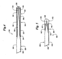
- Figure 4 illustrates yet another embodiment of the invention, a guide wire 320, having a proximal portion 326, followed by an intermediate portion 324, followed distally by a distal portion 322.
- a core 328 proceeds distally from a constant diameter portion 330 to a tapered portion 332, to a reduced diameter portion 334.
- a coil 342 surrounds core 328 over the intermediate and distal portions.
- coil 342 is formed of a proximal coil 323 and a distal coil 325 soldered together at 340.
- Proximal coil 323 is preferably formed from a less radiopaque material such as stainless steel. This coil can be coated with a hydrophobic coating such as PTFE.
- Distal coil 325 is preferably formed of a more radiopaque material such as platinum.
- Combined coil 342 is attached to core 328 proximally with solder at 341 and distally with either solder or welding at 338.
- a hydrophilic coating 336 is applied to the distal portion of distal coil 325 in one embodiment by first applying a Tie layer polymer such as polyurethane by dip or spray coating, followed by applying a hydrophilic coating over the Tie layer coating.
- the hydrophilic coating can be one of the coatings described previously with respect to guide wire 20 in Figure 1.
- Figure 5 illustrates yet another embodiment of the invention, a guide wire 420 having a proximal portion 426, followed by an intermediate portion 424, followed distally by a distal portion 422.
- a core 428 proceeds distally from a contact diameter portion 430 to a tapered portion 432, to a reduced diameter portion 434.
- a distal tip 436 preferably formed of a polymeric substance, surrounds core reduced diameter distal portion 434.
- Distal tip 436 includes a tapered portion 437, which tapers proximally toward core tapered portion 432.
- Guide wire 420 includes a coil 442 which extends distally over core tapered portion 432.
- Coil 442 has a distal end 443 which contacts and terminates within distal tip tapered portion 437. Coil 442 is thus always centered on core 428, as transverse movement of coil distal end 443 is opposed by distal tip tapered portion 437.
- Tip 436 can be heated to embed end 443 therein.
- core reduced diameter portion 34 can be bent by the treating physician, prior to insertion into the patient. Having a bent distal tip allows orienting the tip for insertion into arteries by rotating the proximal end of the guide wire, which rotates the bent distal tip toward arterial side branches.
- the guide wire can be advanced through a guide catheter or directly through the vasculature. After having advanced the guide wire into a coronary artery such as the left coronary artery, the guide wire is maneuvered into selected smaller arteries.
- the lubricous tip In attempting to insinuate the distal most portion of the guide wire into smaller arteries, the lubricous tip provides easier initial advancement into the artery.
- lubricous distal portion 22 When a lesion is to be crossed, lubricous distal portion 22 provides low resistance to axial movement into and through a narrow passage. Low resistance is advantageous as there is less tendency for core reduced diameter portion 34 to kink or buckle when pushed by the treating physician from the extreme proximal end.
- the guide wire tip position not change, despite minor changes in proximal handling of the guide wire, movement of other devices over the guide wire, patient breathing, blood flow, and minor changes in frictional conditions along the guide wire length.
- the present invention allows a guide wire to resist these forces by having intermediate portion 24 lie against and be "anchored" to the vessel or guide catheter wall, presenting a higher quantity of static friction that must be overcome to dislodge the guide wire distal tip, than presented with wires having longer lubricous distal surfaces. The present invention thus makes it less likely that the guide wire will move inside the artery unless the physician is directly intending to move it.
- lubricous distal portion and less lubricous intermediate portion thus serves to promote ease of distal tip advancement across tight lesions while stabilizing the distal tip position once placed, allowing other devices to be accurately guided into position by the guide wire.
Landscapes
- Health & Medical Sciences (AREA)
- Life Sciences & Earth Sciences (AREA)
- Biophysics (AREA)
- Pulmonology (AREA)
- Engineering & Computer Science (AREA)
- Anesthesiology (AREA)
- Biomedical Technology (AREA)
- Heart & Thoracic Surgery (AREA)
- Hematology (AREA)
- Animal Behavior & Ethology (AREA)
- General Health & Medical Sciences (AREA)
- Public Health (AREA)
- Veterinary Medicine (AREA)
- Media Introduction/Drainage Providing Device (AREA)
Description
Claims (15)
- A guide wire (20, 120, 220, 320, 420) having a distal end and a proximal end comprising:an elongate core (28, 128, 228, 328, 428) having a distal core portion, an intermediate core portion proximal of the distal core portion and a proximal core portion proximal of the intermediate core portion,;a lubricous distal guide wire portion (22, 122, 222, 322, 422); anda proximal guide wire portion (26, 126, 226, 326, 426) proximal of said distal guide wire portion (22, 122, 222, 322, 422) and less lubricous than the distal guide wire portion (22, 122, 222, 322, 422), characterized by :an intermediate guide wire portion (24, 124, 224, 324, 424) intermediate said distal portion (22, 122, 222, 322, 422) and said proximal guide wire portion (26, 126, 226, 326, 426), said intermediate guide wire portion (24, 124, 224, 324, 424) being less lubricous than said distal guide wire portion (22, 122, 222, 322, 422) and said proximal guide wire portion (26, 126, 226, 326, 426).
- The guide wire (20, 120, 220, 320, 420) as recited in claim 1, wherein said distal guide wire portion (22, 122, 222, 322, 422) has a hydrophilic surface and said intermediate guide wire portion (24, 124, 224, 324, 424) has a hydrophobic surface.
- The guide wire (20, 120, 220, 320, 420) as recited in claim 2, wherein said distal guide wire portion (22, 122, 222, 322, 422) surface includes a hydrophilic coating, and said intermediate guide wire portion (24, 124, 224, 324, 424) surface includes a hydrophobic coating.
- The guide wire (20, 120, 220, 320, 420) according to anyone of claim 1 to 3, wherein said proximal guide wire portion (26, 126, 226, 326, 426) includes a lubricous coating, in particular polytetrafluoroethylene, over said elongate core (28, 128, 228, 328, 428).
- The guide wire (20, 120, 220, 320, 420) according to claim 1, wherein said intermediate guide wire portion (24, 124, 224, 324, 424) includes a coil (42, 242, 342, 442) around said elongate core (28, 128, 228, 328, 428).
- The guide wire (20, 120, 220, 320, 420) according to claim 5, wherein the coil (42, 242, 342, 442) includes a hydrophobic coating.
- The guide wire (20, 120, 220, 320, 420) as recited in claim 5, said distal guide wire portion (22, 122, 222, 322, 422) including a polymeric distal tip (38, 136, 238, 338, 436) having a proximally tapered proximal portion, said coil (42, 242, 342, 442) having a distal end, wherein said coil distal end contacts said distal tip (38, 136, 238, 338, 436) within said tapered portion (437).
- The guide wire (20, 120, 220, 320, 420) as recited in claim 5 or 7, wherein said elongate core (28, 128, 228, 328, 428) is tapered distally within said intermediate guide wire portion (24, 124, 224, 324, 424).
- The guide wire (20, 120, 220, 320, 420) according to claim 8, wherein said coil (42, 242, 342, 442) comprises stainless steel having a silicone coating or a polytetrafluoroethylene coating.
- The guide wire (20, 120, 220, 320, 420) according to claim 8, wherein said coil (42, 242, 342, 442) includes a distal tapered portion (243), said coil tapered portion (243) extending within said distal guide wire portion (22, 122, 222, 322, 422).
- The guide wire (20, 120, 220, 320, 420) of claim 1, wherein said distal core portion (34, 134, 234, 334, 434) of said elongate core (28, 128, 228, 328, 428) has a reduced cross section; said intermediate core portion of said elongate core (28, 128, 228, 328, 428) has a tapered portion (32, 132, 232, 332, 432) proximal of said distal core portion (34, 134, 234, 334, 434); and said proximal core portion (30, 130, 230, 330, 430) of said elongate core (28, 128, 228, 328, 428) has a uniform cross section.
- The guide wire (20, 120, 220, 320, 420) as recited in claim 11, wherein a wire coil (42, 242, 342, 442) is provided about said tapered core portion (32, 132, 232, 332, 432).
- The guide wire (20, 120, 220, 320, 420) as recited in claim 12, said distal end (422) including a polymeric distal tip (436) having a proximally tapered proximal portion (437), said coil (42, 242, 342, 442) having a distal end, wherein said coil distal end lies within said distal tip tapered portion (437).
- The guide wire (20, 120, 220, 320, 420) according to anyone of claims 11 to 13, wherein a lubricous layer is provided over said reduced cross section core portion surface; and a less lubricous layer is provided over said tapered core portion (32, 132, 232, 332, 432) surface or said coil (42, 242, 342, 442).
- The guide wire (20, 120, 220, 320, 420) as recited in claim 14, wherein said lubricous layer over said reduced cross section core portion surface includes a hydrophilic material, and said lubricous layer over said tapered core portion surface includes a hydrophobic material.
Applications Claiming Priority (3)
| Application Number | Priority Date | Filing Date | Title |
|---|---|---|---|
| US08/812,750 US5924998A (en) | 1997-03-06 | 1997-03-06 | Guide wire with hydrophilically coated tip |
| US812750 | 1997-03-06 | ||
| PCT/US1998/004030 WO1998039049A1 (en) | 1997-03-06 | 1998-03-03 | Guide wire with hydrophilically coated tip |
Publications (2)
| Publication Number | Publication Date |
|---|---|
| EP0914175A1 EP0914175A1 (en) | 1999-05-12 |
| EP0914175B1 true EP0914175B1 (en) | 2004-05-12 |
Family
ID=25210517
Family Applications (1)
| Application Number | Title | Priority Date | Filing Date |
|---|---|---|---|
| EP98906726A Expired - Lifetime EP0914175B1 (en) | 1997-03-06 | 1998-03-03 | Guide wire with hydrophilically coated tip |
Country Status (6)
| Country | Link |
|---|---|
| US (1) | US5924998A (en) |
| EP (1) | EP0914175B1 (en) |
| JP (1) | JP2000509641A (en) |
| CA (1) | CA2251685C (en) |
| DE (1) | DE69823772T2 (en) |
| WO (1) | WO1998039049A1 (en) |
Families Citing this family (60)
| Publication number | Priority date | Publication date | Assignee | Title |
|---|---|---|---|---|
| CA2068584C (en) * | 1991-06-18 | 1997-04-22 | Paul H. Burmeister | Intravascular guide wire and method for manufacture thereof |
| US6251086B1 (en) * | 1999-07-27 | 2001-06-26 | Scimed Life Systems, Inc. | Guide wire with hydrophilically coated tip |
| US6306105B1 (en) | 1998-05-14 | 2001-10-23 | Scimed Life Systems, Inc. | High performance coil wire |
| US6203505B1 (en) * | 1998-06-05 | 2001-03-20 | Advanced Cardiovascular Systems, Inc. | Guidewires having a vapor deposited primer coat |
| WO2000010636A1 (en) * | 1998-08-19 | 2000-03-02 | Cook Incorporated | Preformed wire guide |
| US6292685B1 (en) * | 1998-09-11 | 2001-09-18 | Exergen Corporation | Temporal artery temperature detector |
| US6129750A (en) * | 1999-03-23 | 2000-10-10 | Cardiac Pacemakers, Inc. | Fixation mechanism for a coronary venous pacing lead |
| WO2000065987A1 (en) * | 1999-04-30 | 2000-11-09 | Applied Medical Resources Corporation | Guidewire |
| US6485507B1 (en) | 1999-07-28 | 2002-11-26 | Scimed Life Systems | Multi-property nitinol by heat treatment |
| JP2001238962A (en) * | 2000-02-29 | 2001-09-04 | Japan Lifeline Co Ltd | Medical insertion wire |
| US6494894B2 (en) | 2000-03-16 | 2002-12-17 | Scimed Life Systems, Inc. | Coated wire |
| US6602207B1 (en) | 2000-07-19 | 2003-08-05 | Scimed Life Systems, Inc. | Guide wire stiffness transition element |
| US7097624B2 (en) * | 2000-10-05 | 2006-08-29 | Scimed Life Systems, Inc. | Multi-layer and multi-section coils for guide wire |
| US20040127820A1 (en) * | 2001-09-05 | 2004-07-01 | Clayman Ralph V. | Guidewire |
| AU2003265587A1 (en) * | 2002-08-22 | 2004-03-11 | Cook Incorporated | Guide wire |
| US8162855B2 (en) * | 2002-09-20 | 2012-04-24 | Seven Dreamers Laboratories, Inc. | Medical guide wire and process for production thereof |
| US7044921B2 (en) * | 2003-02-03 | 2006-05-16 | Scimed Life Systems, Inc | Medical device with changeable tip flexibility |
| US7169118B2 (en) * | 2003-02-26 | 2007-01-30 | Scimed Life Systems, Inc. | Elongate medical device with distal cap |
| US7641621B2 (en) | 2003-08-25 | 2010-01-05 | Boston Scientific Scimed, Inc. | Elongated intra-lumenal medical device |
| EP1660168B1 (en) * | 2003-09-05 | 2008-12-10 | Cook Urological Inc. | Double ended wire guide |
| US20050131316A1 (en) * | 2003-12-15 | 2005-06-16 | Cook Incorporated | Guidewire with flexible tip |
| US20060064036A1 (en) * | 2004-09-21 | 2006-03-23 | Cook Incorporated | Variable flexibility wire guide |
| US7819887B2 (en) * | 2004-11-17 | 2010-10-26 | Rex Medical, L.P. | Rotational thrombectomy wire |
| US8784336B2 (en) * | 2005-08-24 | 2014-07-22 | C. R. Bard, Inc. | Stylet apparatuses and methods of manufacture |
| JP4980605B2 (en) * | 2005-11-14 | 2012-07-18 | テルモ株式会社 | Guide wire |
| US7651578B2 (en) * | 2006-06-08 | 2010-01-26 | Boston Scientific Scimed, Inc. | Guidewire with polymer jacket and method of making |
| US20070293791A1 (en) * | 2006-06-16 | 2007-12-20 | Jeong Lee | Guidewire With Lubricious Proximal Portion |
| DE102006047675A1 (en) * | 2006-09-28 | 2008-04-03 | Epflex Feinwerktechnik Gmbh | Guidewire with core and distal sheath |
| US20080119762A1 (en) * | 2006-11-16 | 2008-05-22 | Tateishi Tadasu | Guide wire |
| US7896820B2 (en) * | 2006-12-26 | 2011-03-01 | Terumo Kabushiki Kaisha | Guide wire |
| US7744545B2 (en) * | 2006-12-28 | 2010-06-29 | Terumo Kabushiki Kaisha | Guide wire |
| JP5020630B2 (en) * | 2006-12-28 | 2012-09-05 | テルモ株式会社 | Guide wire |
| JP5214878B2 (en) * | 2006-12-28 | 2013-06-19 | テルモ株式会社 | Guide wire |
| JP4917900B2 (en) * | 2007-01-12 | 2012-04-18 | テルモ株式会社 | Intermediate member for guide wire and guide wire |
| US8206837B2 (en) * | 2007-01-12 | 2012-06-26 | Terumo Kabushiki Kaisha | Interventional medical device |
| JP4981471B2 (en) * | 2007-02-09 | 2012-07-18 | テルモ株式会社 | Guide wire |
| JP2008237253A (en) * | 2007-03-23 | 2008-10-09 | Terumo Corp | Guide wire |
| JP2008245852A (en) * | 2007-03-29 | 2008-10-16 | Terumo Corp | Guide wire |
| JP5295104B2 (en) * | 2007-05-09 | 2013-09-18 | 独立行政法人科学技術振興機構 | Guidewire and stent |
| JP5441336B2 (en) * | 2007-05-11 | 2014-03-12 | テルモ株式会社 | Guide wire |
| US20100292781A1 (en) * | 2008-01-11 | 2010-11-18 | Sandhu Gurpreet S | Stent advancement assistant and lesion dilator wire |
| WO2009100129A2 (en) | 2008-02-05 | 2009-08-13 | Chad John Kugler | Crossing occlusions in blood vessels |
| US8337425B2 (en) | 2008-02-05 | 2012-12-25 | Bridgepoint Medical, Inc. | Endovascular device with a tissue piercing distal probe and associated methods |
| US8002715B2 (en) | 2008-05-30 | 2011-08-23 | Boston Scientific Scimed, Inc. | Medical device including a polymer sleeve and a coil wound into the polymer sleeve |
| US20110172604A1 (en) * | 2008-09-12 | 2011-07-14 | C. R. Bard, Inc. | Hybrid guidewire |
| US8444577B2 (en) | 2009-01-05 | 2013-05-21 | Cook Medical Technologies Llc | Medical guide wire |
| JP5323520B2 (en) * | 2009-02-03 | 2013-10-23 | テルモ株式会社 | MEDICAL LONG UNIT CONTAINER AND MEDICAL LONG UNIT CONTAINER ASSEMBLY |
| US9023070B2 (en) | 2010-05-13 | 2015-05-05 | Rex Medical, L.P. | Rotational thrombectomy wire coupler |
| US9795406B2 (en) | 2010-05-13 | 2017-10-24 | Rex Medical, L.P. | Rotational thrombectomy wire |
| US8764779B2 (en) | 2010-05-13 | 2014-07-01 | Rex Medical, L.P. | Rotational thrombectomy wire |
| US8663259B2 (en) | 2010-05-13 | 2014-03-04 | Rex Medical L.P. | Rotational thrombectomy wire |
| US20120083710A1 (en) | 2010-09-30 | 2012-04-05 | Medism Ltd. | Ergonomic hand-held thermometer |
| JP2012200290A (en) * | 2011-03-23 | 2012-10-22 | Asahi Intecc Co Ltd | Guidewire |
| JP5392792B2 (en) * | 2011-06-06 | 2014-01-22 | 朝日インテック株式会社 | Guide wire |
| US11090465B2 (en) | 2014-08-21 | 2021-08-17 | Boston Scientific Scimed, Inc. | Medical device with support member |
| JP6400448B2 (en) * | 2014-11-29 | 2018-10-03 | 株式会社Pentas | Stent delivery system |
| US11801368B2 (en) | 2017-05-25 | 2023-10-31 | C.R. Bard, Inc. | Guidewire |
| US11471651B2 (en) * | 2020-06-22 | 2022-10-18 | Medtronic, Inc. | Balloon catheter including a guidewire tube with a friction-increasing outer coating |
| CN112587782B (en) * | 2020-12-07 | 2023-05-30 | 上海璞慧医疗器械有限公司 | Medical guide wire |
| JP2022191593A (en) * | 2021-06-16 | 2022-12-28 | 朝日インテック株式会社 | Resin coating wire and chemical injection device |
Family Cites Families (50)
| Publication number | Priority date | Publication date | Assignee | Title |
|---|---|---|---|---|
| FR2401668A1 (en) * | 1977-08-31 | 1979-03-30 | Plowiecki Leopold | Blood vessel probe elastic guide - comprises straight wire sealed into low-friction plastics tube |
| CA1153264A (en) * | 1979-02-08 | 1983-09-06 | Hidenaga Yoshimura | Medical vascular guide wire and self-guiding type catheter |
| US4282876A (en) * | 1979-05-18 | 1981-08-11 | Flynn Vincent J | Radiopaque polyurethane resin compositions |
| JPS5886129A (en) * | 1981-11-17 | 1983-05-23 | 旭光学工業株式会社 | Flexible tube of endoscope and production thereof |
| US4534363A (en) * | 1982-04-29 | 1985-08-13 | Cordis Corporation | Coating for angiographic guidewire |
| US4456017A (en) * | 1982-11-22 | 1984-06-26 | Cordis Corporation | Coil spring guide with deflectable tip |
| JPS6012069A (en) * | 1983-06-30 | 1985-01-22 | 日本ゼオン株式会社 | Guide wire having anti-thrombotic property imparted thereto and production thereof |
| CA1232814A (en) * | 1983-09-16 | 1988-02-16 | Hidetoshi Sakamoto | Guide wire for catheter |
| EP0157862B1 (en) * | 1983-10-04 | 1991-03-20 | MÄRZ, Peter, Dr. | Guiding mandrel for catheter and similar instruments and manufacturing process thereof |
| US4835003A (en) * | 1985-04-17 | 1989-05-30 | Baxter International Inc. | Medical tubing with water-activated lubricating coating |
| US4642267A (en) * | 1985-05-06 | 1987-02-10 | Hydromer, Inc. | Hydrophilic polymer blend |
| US4682607A (en) * | 1985-12-02 | 1987-07-28 | Vlv Associates | Wire guide |
| US4729914A (en) * | 1985-12-30 | 1988-03-08 | Tyndale Plains-Hunter Ltd. | Hydrophilic coating and substrate coated therewith |
| US4721117A (en) * | 1986-04-25 | 1988-01-26 | Advanced Cardiovascular Systems, Inc. | Torsionally stabilized guide wire with outer jacket |
| US4739768B2 (en) * | 1986-06-02 | 1995-10-24 | Target Therapeutics Inc | Catheter for guide-wire tracking |
| JPS63171570A (en) * | 1987-01-07 | 1988-07-15 | テルモ株式会社 | Guide wire for catheter |
| US4811743A (en) * | 1987-04-21 | 1989-03-14 | Cordis Corporation | Catheter guidewire |
| US4867174A (en) * | 1987-11-18 | 1989-09-19 | Baxter Travenol Laboratories, Inc. | Guidewire for medical use |
| US4841976A (en) * | 1987-12-17 | 1989-06-27 | Schneider-Shiley (Usa) Inc. | Steerable catheter guide |
| US5078702A (en) * | 1988-03-25 | 1992-01-07 | Baxter International Inc. | Soft tip catheters |
| AU611030B2 (en) * | 1988-04-07 | 1991-05-30 | Edward Shanbrom | Non-thrombogenic intravascular time release catheter |
| US4884579A (en) * | 1988-04-18 | 1989-12-05 | Target Therapeutics | Catheter guide wire |
| US4961731A (en) * | 1988-06-09 | 1990-10-09 | Sherwood Medical Company | Angiographic catheter with balanced dye injection openings |
| CA1323539C (en) * | 1988-08-16 | 1993-10-26 | Stuart J. Lind | Flexible guide with safety tip |
| US4977901A (en) * | 1988-11-23 | 1990-12-18 | Minnesota Mining And Manufacturing Company | Article having non-crosslinked crystallized polymer coatings |
| JP2610507B2 (en) * | 1988-12-29 | 1997-05-14 | テルモ株式会社 | Guide wire |
| CA2007743A1 (en) * | 1989-01-26 | 1990-07-26 | Sachiko Hattori | Vascular catheter with durable lubricious coating |
| US4922924A (en) * | 1989-04-27 | 1990-05-08 | C. R. Bard, Inc. | Catheter guidewire with varying radiopacity |
| US5069226A (en) * | 1989-04-28 | 1991-12-03 | Tokin Corporation | Catheter guidewire with pseudo elastic shape memory alloy |
| US4955862A (en) * | 1989-05-22 | 1990-09-11 | Target Therapeutics, Inc. | Catheter and catheter/guide wire device |
| US5045072A (en) * | 1989-06-13 | 1991-09-03 | Cordis Corporation | Catheter having highly radiopaque, flexible tip |
| US5061254A (en) * | 1989-06-21 | 1991-10-29 | Becton, Dickinson And Company | Thermoplastic elastomeric hydrophilic polyetherurethane expandable catheter |
| US4991602A (en) * | 1989-06-27 | 1991-02-12 | Flexmedics Corporation | Flexible guide wire with safety tip |
| WO1991000051A1 (en) * | 1989-06-28 | 1991-01-10 | Boston Scientific Corporation | Steerable highly elongated guidewire |
| CA2019063E (en) * | 1989-06-29 | 2000-01-04 | Brian L. Bates | Hydrophilically coated flexible wire guide |
| JP2540211B2 (en) * | 1989-07-10 | 1996-10-02 | テルモ株式会社 | Guide wire |
| US5095915A (en) * | 1990-03-19 | 1992-03-17 | Target Therapeutics | Guidewire with flexible distal tip |
| CA2068584C (en) * | 1991-06-18 | 1997-04-22 | Paul H. Burmeister | Intravascular guide wire and method for manufacture thereof |
| US5333620A (en) * | 1991-10-30 | 1994-08-02 | C. R. Bard, Inc. | High performance plastic coated medical guidewire |
| US5342383A (en) * | 1992-03-27 | 1994-08-30 | Thomas Medical Products, Inc. | Soft tip obturator |
| US5772609A (en) * | 1993-05-11 | 1998-06-30 | Target Therapeutics, Inc. | Guidewire with variable flexibility due to polymeric coatings |
| US5769796A (en) * | 1993-05-11 | 1998-06-23 | Target Therapeutics, Inc. | Super-elastic composite guidewire |
| JPH0737199U (en) * | 1993-12-24 | 1995-07-11 | テルモ株式会社 | Guide wire |
| US5606981A (en) * | 1994-03-11 | 1997-03-04 | C. R. Bard, Inc. | Catheter guidewire with radiopaque markers |
| ATE193834T1 (en) * | 1995-03-02 | 2000-06-15 | Schneider Europ Gmbh | METHOD FOR PRODUCING A GUIDE WIRE |
| JP3761214B2 (en) * | 1995-03-20 | 2006-03-29 | 株式会社パイオラックス | Medical guidewire |
| JPH11504829A (en) * | 1995-05-05 | 1999-05-11 | アドバンスト・カーディオバスキュラー・システムズ・インコーポレイテッド | In-pipe device with anti-friction surface |
| DE69600950T2 (en) * | 1995-05-26 | 1999-04-01 | Target Therapeutics Inc | Super elastic composite guide wire |
| JP2987555B2 (en) * | 1995-08-28 | 1999-12-06 | 朝日インテック株式会社 | Medical guidewire |
| US5722424A (en) * | 1995-09-29 | 1998-03-03 | Target Therapeutics, Inc. | Multi-coating stainless steel guidewire |
-
1997
- 1997-03-06 US US08/812,750 patent/US5924998A/en not_active Expired - Fee Related
-
1998
- 1998-03-03 EP EP98906726A patent/EP0914175B1/en not_active Expired - Lifetime
- 1998-03-03 DE DE69823772T patent/DE69823772T2/en not_active Expired - Fee Related
- 1998-03-03 JP JP10538653A patent/JP2000509641A/en active Pending
- 1998-03-03 WO PCT/US1998/004030 patent/WO1998039049A1/en active IP Right Grant
- 1998-03-03 CA CA002251685A patent/CA2251685C/en not_active Expired - Fee Related
Also Published As
| Publication number | Publication date |
|---|---|
| CA2251685A1 (en) | 1998-09-11 |
| DE69823772T2 (en) | 2005-05-25 |
| WO1998039049A1 (en) | 1998-09-11 |
| CA2251685C (en) | 2008-11-18 |
| US5924998A (en) | 1999-07-20 |
| DE69823772D1 (en) | 2004-06-17 |
| EP0914175A1 (en) | 1999-05-12 |
| JP2000509641A (en) | 2000-08-02 |
Similar Documents
| Publication | Publication Date | Title |
|---|---|---|
| EP0914175B1 (en) | Guide wire with hydrophilically coated tip | |
| US6251086B1 (en) | Guide wire with hydrophilically coated tip | |
| US6402706B2 (en) | Guide wire with multiple polymer jackets over distal and intermediate core sections | |
| US6296616B1 (en) | Guidewire with shaped intermediate portion | |
| CA2228346C (en) | Guidewire having a distal tip that can change its shape within a vessel | |
| EP0749334B2 (en) | Catheter guidewire with radiopaque markers | |
| EP0823261B1 (en) | Guidewire having a distal tip that can change its shape within a vessel | |
| US4922924A (en) | Catheter guidewire with varying radiopacity | |
| US6669652B2 (en) | Guidewire with tapered distal coil | |
| US5147317A (en) | Low friction varied radiopacity guidewire | |
| US6132389A (en) | Proximally tapered guidewire tip coil | |
| US6139511A (en) | Guidewire with variable coil configuration | |
| US5063935A (en) | Catheter guidewire with varying radiopacity | |
| US6036682A (en) | Catheter having a plurality of integral radiopaque bands | |
| US20050131316A1 (en) | Guidewire with flexible tip | |
| US20030013993A1 (en) | Guidewire with smoothly tapered segment | |
| US20080269641A1 (en) | Method of using a guidewire with stiffened distal section | |
| WO1992019151A1 (en) | Catheter guide wire | |
| JP3380691B2 (en) | Guide wire | |
| US20090312670A1 (en) | Wire guide having a rib for coil attachment | |
| US6126650A (en) | Flow directed catheter having radiopaque strain relief segment | |
| JPH0728562U (en) | Guide wire | |
| JP3998918B2 (en) | Guide wire | |
| WO2010060889A1 (en) | Microcatheter | |
| WO2022158418A1 (en) | Catheter |
Legal Events
| Date | Code | Title | Description |
|---|---|---|---|
| PUAI | Public reference made under article 153(3) epc to a published international application that has entered the european phase |
Free format text: ORIGINAL CODE: 0009012 |
|
| 17P | Request for examination filed |
Effective date: 19981022 |
|
| AK | Designated contracting states |
Kind code of ref document: A1 Designated state(s): BE DE FR GB IE NL |
|
| 17Q | First examination report despatched |
Effective date: 20021024 |
|
| GRAP | Despatch of communication of intention to grant a patent |
Free format text: ORIGINAL CODE: EPIDOSNIGR1 |
|
| GRAS | Grant fee paid |
Free format text: ORIGINAL CODE: EPIDOSNIGR3 |
|
| GRAA | (expected) grant |
Free format text: ORIGINAL CODE: 0009210 |
|
| AK | Designated contracting states |
Kind code of ref document: B1 Designated state(s): BE DE FR GB IE NL |
|
| PG25 | Lapsed in a contracting state [announced via postgrant information from national office to epo] |
Ref country code: BE Free format text: LAPSE BECAUSE OF FAILURE TO SUBMIT A TRANSLATION OF THE DESCRIPTION OR TO PAY THE FEE WITHIN THE PRESCRIBED TIME-LIMIT Effective date: 20040512 |
|
| REG | Reference to a national code |
Ref country code: GB Ref legal event code: FG4D |
|
| REG | Reference to a national code |
Ref country code: IE Ref legal event code: FG4D |
|
| REF | Corresponds to: |
Ref document number: 69823772 Country of ref document: DE Date of ref document: 20040617 Kind code of ref document: P |
|
| ET | Fr: translation filed | ||
| PLAQ | Examination of admissibility of opposition: information related to despatch of communication + time limit deleted |
Free format text: ORIGINAL CODE: EPIDOSDOPE2 |
|
| PLBQ | Unpublished change to opponent data |
Free format text: ORIGINAL CODE: EPIDOS OPPO |
|
| PLAQ | Examination of admissibility of opposition: information related to despatch of communication + time limit deleted |
Free format text: ORIGINAL CODE: EPIDOSDOPE2 |
|
| PLBI | Opposition filed |
Free format text: ORIGINAL CODE: 0009260 |
|
| PLBQ | Unpublished change to opponent data |
Free format text: ORIGINAL CODE: EPIDOS OPPO |
|
| 26 | Opposition filed |
Opponent name: TERUMO KABUSHIKI KAISHA Effective date: 20050210 |
|
| PLAB | Opposition data, opponent's data or that of the opponent's representative modified |
Free format text: ORIGINAL CODE: 0009299OPPO |
|
| PLAQ | Examination of admissibility of opposition: information related to despatch of communication + time limit deleted |
Free format text: ORIGINAL CODE: EPIDOSDOPE2 |
|
| PLAR | Examination of admissibility of opposition: information related to receipt of reply deleted |
Free format text: ORIGINAL CODE: EPIDOSDOPE4 |
|
| PLAX | Notice of opposition and request to file observation + time limit sent |
Free format text: ORIGINAL CODE: EPIDOSNOBS2 |
|
| PLBQ | Unpublished change to opponent data |
Free format text: ORIGINAL CODE: EPIDOS OPPO |
|
| NLR1 | Nl: opposition has been filed with the epo |
Opponent name: TERUMO KABUSHIKI KAISHA |
|
| R26 | Opposition filed (corrected) |
Opponent name: TERUMO KABUSHIKI KAISHA Effective date: 20050210 |
|
| NLR1 | Nl: opposition has been filed with the epo |
Opponent name: TERUMO KABUSHIKI KAISHA |
|
| PLAF | Information modified related to communication of a notice of opposition and request to file observations + time limit |
Free format text: ORIGINAL CODE: EPIDOSCOBS2 |
|
| RAP2 | Party data changed (patent owner data changed or rights of a patent transferred) |
Owner name: BOSTON SCIENTIFIC SCIMED, INC. |
|
| PLBB | Reply of patent proprietor to notice(s) of opposition received |
Free format text: ORIGINAL CODE: EPIDOSNOBS3 |
|
| NLT2 | Nl: modifications (of names), taken from the european patent patent bulletin |
Owner name: BOSTON SCIENTIFIC SCIMED, INC. Effective date: 20051221 |
|
| PLCK | Communication despatched that opposition was rejected |
Free format text: ORIGINAL CODE: EPIDOSNREJ1 |
|
| APBP | Date of receipt of notice of appeal recorded |
Free format text: ORIGINAL CODE: EPIDOSNNOA2O |
|
| APAH | Appeal reference modified |
Free format text: ORIGINAL CODE: EPIDOSCREFNO |
|
| APBQ | Date of receipt of statement of grounds of appeal recorded |
Free format text: ORIGINAL CODE: EPIDOSNNOA3O |
|
| PGFP | Annual fee paid to national office [announced via postgrant information from national office to epo] |
Ref country code: IE Payment date: 20090128 Year of fee payment: 12 |
|
| PGFP | Annual fee paid to national office [announced via postgrant information from national office to epo] |
Ref country code: NL Payment date: 20090310 Year of fee payment: 12 |
|
| PGFP | Annual fee paid to national office [announced via postgrant information from national office to epo] |
Ref country code: GB Payment date: 20090206 Year of fee payment: 12 |
|
| PLAB | Opposition data, opponent's data or that of the opponent's representative modified |
Free format text: ORIGINAL CODE: 0009299OPPO |
|
| PGFP | Annual fee paid to national office [announced via postgrant information from national office to epo] |
Ref country code: DE Payment date: 20090331 Year of fee payment: 12 |
|
| PGFP | Annual fee paid to national office [announced via postgrant information from national office to epo] |
Ref country code: FR Payment date: 20090306 Year of fee payment: 12 |
|
| APBU | Appeal procedure closed |
Free format text: ORIGINAL CODE: EPIDOSNNOA9O |
|
| REG | Reference to a national code |
Ref country code: NL Ref legal event code: V1 Effective date: 20101001 |
|
| PLBN | Opposition rejected |
Free format text: ORIGINAL CODE: 0009273 |
|
| STAA | Information on the status of an ep patent application or granted ep patent |
Free format text: STATUS: OPPOSITION REJECTED |
|
| 27O | Opposition rejected |
Effective date: 20100721 |
|
| GBPC | Gb: european patent ceased through non-payment of renewal fee |
Effective date: 20100303 |
|
| REG | Reference to a national code |
Ref country code: IE Ref legal event code: MM4A |
|
| REG | Reference to a national code |
Ref country code: FR Ref legal event code: ST Effective date: 20101130 |
|
| PG25 | Lapsed in a contracting state [announced via postgrant information from national office to epo] |
Ref country code: NL Free format text: LAPSE BECAUSE OF NON-PAYMENT OF DUE FEES Effective date: 20101001 Ref country code: IE Free format text: LAPSE BECAUSE OF NON-PAYMENT OF DUE FEES Effective date: 20100303 Ref country code: FR Free format text: LAPSE BECAUSE OF NON-PAYMENT OF DUE FEES Effective date: 20100331 |
|
| PG25 | Lapsed in a contracting state [announced via postgrant information from national office to epo] |
Ref country code: DE Free format text: LAPSE BECAUSE OF NON-PAYMENT OF DUE FEES Effective date: 20101001 |
|
| PG25 | Lapsed in a contracting state [announced via postgrant information from national office to epo] |
Ref country code: GB Free format text: LAPSE BECAUSE OF NON-PAYMENT OF DUE FEES Effective date: 20100303 |