EP0913166A2 - Elektrostimulator - Google Patents
Elektrostimulator Download PDFInfo
- Publication number
- EP0913166A2 EP0913166A2 EP98250385A EP98250385A EP0913166A2 EP 0913166 A2 EP0913166 A2 EP 0913166A2 EP 98250385 A EP98250385 A EP 98250385A EP 98250385 A EP98250385 A EP 98250385A EP 0913166 A2 EP0913166 A2 EP 0913166A2
- Authority
- EP
- European Patent Office
- Prior art keywords
- pulse
- electrode
- output
- stimulation
- pacemaker
- Prior art date
- Legal status (The legal status is an assumption and is not a legal conclusion. Google has not performed a legal analysis and makes no representation as to the accuracy of the status listed.)
- Granted
Links
Images


Classifications
-
- A—HUMAN NECESSITIES
- A61—MEDICAL OR VETERINARY SCIENCE; HYGIENE
- A61N—ELECTROTHERAPY; MAGNETOTHERAPY; RADIATION THERAPY; ULTRASOUND THERAPY
- A61N1/00—Electrotherapy; Circuits therefor
- A61N1/18—Applying electric currents by contact electrodes
- A61N1/32—Applying electric currents by contact electrodes alternating or intermittent currents
- A61N1/36—Applying electric currents by contact electrodes alternating or intermittent currents for stimulation
- A61N1/362—Heart stimulators
- A61N1/37—Monitoring; Protecting
- A61N1/371—Capture, i.e. successful stimulation
-
- A—HUMAN NECESSITIES
- A61—MEDICAL OR VETERINARY SCIENCE; HYGIENE
- A61N—ELECTROTHERAPY; MAGNETOTHERAPY; RADIATION THERAPY; ULTRASOUND THERAPY
- A61N1/00—Electrotherapy; Circuits therefor
- A61N1/18—Applying electric currents by contact electrodes
- A61N1/32—Applying electric currents by contact electrodes alternating or intermittent currents
- A61N1/36—Applying electric currents by contact electrodes alternating or intermittent currents for stimulation
- A61N1/362—Heart stimulators
- A61N1/37—Monitoring; Protecting
- A61N1/3706—Pacemaker parameters
Definitions
- the invention relates to an electrical stimulator according to the Preamble of claim 1.
- each stimulation pulse results in a partial discharge of the pacemaker battery leads to an extension the battery life strives, the amplitude of the Lower stimulation pulses as much as possible, however It should be noted that the heart is stimulated with a Amplitude below a certain threshold - also known as a stimulus threshold - no longer with one Contraction responds.
- a so-called stimulus threshold test to carry out the stimulus threshold of the Heart for each pacemaker wearer determine and the amplitude of the stimulation pulses accordingly to be able to program.
- the pacemaker gives this successively stimulation pulses with decreasing Amplitude, whereby by evaluating an extracorporeal electrocardiogram (EKG) is whether the heart is on the previous stimulation pulse reacted with a contraction.
- EKG extracorporeal electrocardiogram
- the stimulus threshold of the heart corresponds approximately to the amplitude, where the heart is just excited by the stimulation pulse has been.
- Threshold threshold for example, due to changes in the chronic stimulation threshold in normal operation of the pacemaker is not recognized, which leads to either Stimulation with unnecessarily high amplitudes or - essential worse - can lead to unsuccessful stimulation.
- pacemakers are now known that independently determine whether the heart from a stimulation pulse is successfully stimulated, and the amplitude of the Optimize stimulation pulses accordingly. To do this measures the pacemaker via the pacemaker electrode in each case immediately after a stimulation pulse the so-called evoked potential that the heart muscle contraction evokes and the stimulus response to the previous stimulation pulse represents.
- the problem here is that the electrode system, which has two metal-electrolyte interfaces includes, due to its capacitive properties electrically charged by a stimulation pulse is so that the evoked potentials of the electrical after-effects of a stimulation pulse (Artifacts on both boundary layer capacities) covered can be. This concept is therefore only suitable for Relation to high-capacity electrodes due to their large capacity from a stimulation pulse only a relatively low voltage can be charged which the Detection of the evoked potential does not interfere.
- the invention is therefore based on the object of an electrostimulator to create the measurement of electrode capacity even when implanted without separate devices enables.
- the task is based on an electrostimulator the preamble of claim 1, by the characterizing Features resolved.
- the invention includes the technical teaching for measurement the capacitance or the complex impedance of the working electrode integrate a measuring device into the stimulator arrangement, the voltage when a pulse is given and / or the current at the output port as the interface between stimulator and working or stimulation electrode measures, and by means of an evaluation device the measured values reflecting the electrode capacity To calculate output signal.
- the invention is not limited to in vivo applications, but rather also refers to the in vitro area using electrolyte solutions.
- the pulse generator for determining the electrode capacity generates a pulse with a predetermined electrical charge Q , for example a constant current pulse with a predetermined amplitude and duration.
- the invention is not limited to a constant current pulse. It is crucial that the electrical charge Q emitted with the pulse or the current flowing during the pulse duration is known. For this purpose, it is optionally possible to generate a pulse with a predetermined charge or to measure the time during the delivery of a pulse with a known current profile.
- a constant current pulse is preferably used.
- Electrode system can use the constant current pulse as a double pulse with mutually inverse current direction of the two partial pulses be carried out.
- Another variant of the invention provides for Determination of the electrode capacity a pulse with a predetermined Voltage curve, preferably a constant voltage pulse, to deliver.
- the stimulation electrode is considered electrically as a series connection of a capacitance C El and an ohmic resistance R El , the voltage across the electrode capacitance increases exponentially during the pulse duration during a pulse voltage and approaches the voltage amplitude U Stim of the pulse asymptotically.
- the pacemaker electrode is Part of a resonant circuit, the Electrode capacity due to its influence on the Vibration behavior of the resonant circuit can be determined can.
- the pacemaker shows internally an inductor connected to the output terminal or can be connected by a switching element. The inductance can be selected with the electrode capacity can be connected in series or in parallel.
- the suggestion of resonant circuit thus formed is carried out by a Vibration generator, which can also be used with the Interface connected or with this by a switching element is connectable.
- the Vibration generator a preferably sinusoidal vibration signal constant frequency and voltage amplitude, so that the current flowing through the resonant circuit from the frequency tuning between vibration generator on the one hand and oscillating circuit depends on the other.
- the measurement of over the interface of flowing current then enables the calculation the electrode capacity from the frequency of the Vibration generator and the inductance of the resonant circuit.
- Another variant is the measurement of an impedance spectrogram of the electrode system with a continuous Vibration generator.
- a continuous Vibration generator By embossing one frequency variable constant current or constant voltage signal and measurement of voltage or current on the electrode system the course of the electrode impedance depending picked up by the signal frequency. From the spectrum the Helmholtz capacity and also the electrolyte and Faraday resistance can be calculated.
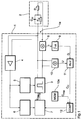
- the pacemaker shown in Figure 1 as a block diagram 1 enables via a - here in the equivalent circuit diagram shown - stimulation electrode 2 the delivery of stimulation pulses to the heart.
- a - here in the equivalent circuit diagram shown - stimulation electrode 2 the delivery of stimulation pulses to the heart.
- - stimulation electrode 2 the delivery of stimulation pulses to the heart.
- For simplification here is only one of the electrode-electrolyte interfaces of the electrode system shown in the equivalent circuit diagram.
- the equivalent circuit diagram of the pacemaker electrode 2 to be arranged endocardially is intended to reflect the essential electrical properties of the metal / tissue boundary layer on the pacemaker electrode.
- a so-called Helmholtz double layer is formed at the boundary layer between the pacemaker electrode 2 and the surrounding tissue (not shown), which is simulated by connecting a capacitor C H and an ohmic resistor R F in parallel, whereby it should be noted that the ohmic Resistance R F of the Helmholtz double layer is strongly dependent on the electrode potential.
- the pacemaker electrode 2 has an ohmic line resistance R L , which is connected in series with the above-described impedance of the Helmholtz double layer, and - strictly speaking - an electrolyte resistance (important for small electrode areas) which is in series with it, but which is not separate here is shown.
- the pacemaker electrode 2 enables delivery of stimulation pulses to the heart.
- the generation of the Stimulation pulses are carried out in a conventional manner by the pulse generator shown in more detail in FIG 3, the output side for connecting the pacemaker electrode 2 has an output terminal 1a.
- the pacemaker electrode 2 is used for detection that stems from spontaneous, non-stimulated heart actions electrical activity of the heart to the delivery inhibit a stimulation pulse if necessary can.
- this is the heart's own rhythm largely maintained.
- the other is like this avoiding unnecessary stimulation, resulting in an extension contributes to the battery life of the pacemaker 1.
- the pacemaker 1 has an input amplifier 4 on the pacemaker electrode 2 recorded electrical cardiac signals amplified and Detection of spontaneous heart actions using a signal detector 5 feeds. If the signal detector 5 detects a spontaneous heart action, so it gives an inhibition signal to the pulse generator 3, which then resets its internal timers and suspend delivery of a stimulation pulse.
- the stimulation electrode 2 also enables the detection of the stimulus response of the heart what ultimately an adjustment of the strength of the stimulation impulses to the individual pacing threshold of the pacemaker wearer enables.
- Successful stimulation of the heart is simplified said - ahead that the amplitude time area of the individual stimulation impulses the individual stimulus threshold for the heart to respond to a stimulation pulse reacted with a contraction.
- the amplitude time area of the stimulation pulses if possible to lower far in order to extend the Battery life to save energy.
- the pacemaker 1 therefore checks the after each stimulation pulse electrical received via the pacemaker electrode 2 Heart signals and determines whether evoked potentials occur the stimulus response to the immediately preceding one Represent stimulation pulse.
- the output signal of the input amplifier 4 is therefore evoked for detection Potentials supplied to a special signal detector 6.
- the strength of the stimulation pulses is set by a control circuit 7, which is connected on the input side to the signal detector 6 and slowly lowers the stimulation voltage U Stim as long as the heart is excited and increases the stimulation voltage in steps if no contraction of the heart muscle is detected following a stimulation pulse becomes.
- transistor T 1 shown in FIG. 2 is closed by control electronics (not shown here), while transistor T 2 is open. Since the output capacitor C a is completely discharged at the beginning of a stimulation pulse, the full voltage U Stim is initially present at the interface. During the duration of the stimulation pulse , however, the output capacitor C a is charged by the current flowing through the interface, which leads to an exponential decrease in the voltage applied to the interface during each pulse. The output capacitor C a thus limits the maximum charge flowing off during a stimulation pulse to the value which - with a simplified assumption of a purely ohmic load - is required to charge the output capacitor C a to the full voltage U Stim .
- the voltage of the output capacitor C a reduces the maximum stimulation voltage that can be achieved with the next stimulation pulse, so that no new pulse with the full voltage can be generated immediately after a stimulation pulse.
- the charging of the electrode capacity C H disturbs the measurement of the natural heart activity, since the electrical heart signals are superimposed by the voltage of the electrode capacity C H.
- the transistor T 2 is therefore closed while the transistor T 1 is open, so that the output capacitor C a and the electrode capacitance C H discharge relatively quickly.
- the unloading process proceeds sufficiently quickly to be able to detect the next natural, non-stimulated heart action after a stimulation pulse, which is relatively simple, since the heart does not show any spontaneous activity anyway during the refractory period following a stimulation.
- the detection of the stimulus response of the heart is essential more difficult because the evoked potentials in very short time interval to the stimulation pulse occur.
- the measurement of the stimulus response is therefore only for high capacitive electrodes possible by a stimulation pulse due to their large capacity only one relatively low voltage can be charged after the Autoshort does not measure the evoked potentials disturbs.
- the automatic optimization of the The amplitude of the stimulation pulses is therefore sufficient large capacity of the pacemaker electrode 2 ahead. If the electrode capacity is too low, this should Function, however, be switched to inactive.
- the pacemaker 1 therefore determines the capacity of the Electrode system (and thus indirectly the pacemaker electrode 2) and turns on the automatic optimization of the Pulse strength off if the capacity is a given Falls below the minimum value.
- the pacemaker 1 has a current measuring device 8 on, which is arranged in the output circuit and at each Stimulation pulse or special measuring pulse the flowing Electricity measures.
- the output signal of the current measuring device 8 is subsequently fed to an integrator 9, which consists of the Current flow that flows during a stimulation pulse electrical charge determined.
- a voltage measuring device 10 provided that immediately after the end a stimulation pulse or after or during a Measuring pulse measures the voltage at the interface, which in the essentially equal to the charging voltage of the electrode capacity is. In the case of a constant current measurement (see a current meter is not required.
- the electrode capacitance C H determined in this way is fed to an input of a comparator unit 12, in which it is compared with a minimum value C Min present at the other input, which is required to detect the evoked potentials and thus to carry out the automatic optimization of the pulse amplitude and in one programmable comparison value memory 12a is stored.
- the control circuit 7 sets the stimulation amplitude to a preset value, which ensures safe stimulation of the heart.
- the voltage curve at the various components in the output circuit is shown in detail in FIG. 3a, it being assumed that a constant voltage pulse with the amplitude U Stim is generated in front of the output capacitor . Since both the output capacitor and the electrode capacitance are completely discharged at the start of the stimulation pulse, the entire stimulation voltage initially drops across the ohmic resistors arranged in the output circuit. During the stimulation pulse, however, the two capacitors are charged, so that the current drops exponentially.
- FIG. 3b shows the voltage curve which can be measured at the output connection for the pacemaker electrode.
- the output voltage at the beginning of the stimulation pulse corresponds to the entire voltage U Stim , since the output capacitor is initially empty.
- the current in the output circuit suddenly drops to zero, so that the output voltage drops to the voltage across the electrode capacity, which enables the electrode capacity to be determined by a simple voltage measurement immediately after the end of the stimulation pulse.
- the voltage measurement should preferably not be immediately after the end of the measuring pulse, but only after a predetermined decay time of a few milliseconds.
- both a potential pulse and a constant current measurement are strictly speaking at the electrode not only the voltage after the pulse, but the voltage difference after and before the pulse must be measured since the actual artifact is one Offset voltage (unknown without previous measurement) overlaid is.
- FIG. 1 would be a measurement value memory and a subtraction stage - the voltage measuring device 10 after and upstream of the ALU 11 - to be completed.
- the measurement technique described above can be advantageous be modified so that a constant current is applied. This is to keep the through the measuring electrode flowing current is a galvanostatic Control loop formed, which - in a manner known per se - one current-carrying counter electrode and basically also a current-free reference electrode and a measuring current and includes a power amplifier.
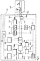
- FIG. 4 again in the form of a functional block diagram, a modified compared to Fig. 1 of a pacemaker.
- Functional components are based on FIG. 1 Reference numbers (for example for the electrode number 102 as functionally essentially in accordance with number 2) referred to and will not be explained again below.
- the pacemaker outlined in Fig. 4 differs of that shown in Fig. 1 mainly by means for adaptation of the stimulation rate and a changed measurement and Evaluation arrangement for testing the electrode capacity.
- the means (known per se) for rate adaptation include one downstream of the output of the input amplifier 4 QT interval detector 117 and one with its output connected rate adaptation circuit 118.
- the QT interval detector 117 becomes the time interval between a stimulation pulse and a predetermined portion of the evoked Heart signal (T wave) detected, and in the rate adaptation circuit 118 is based on the measured time interval and a rate control signal based on a pre-stored table of values generated that eventually the stimulation pulse generator 103 is supplied.
- the Function of the rate adaptation circuit 118 via an output side connected to the rate adaptation circuit second control circuit 107B are inhibited if the Electrode capacity is too low and therefore the danger there is that the evoked detected by the electrode 102 Potentials are falsified.
- the frequency of the alternator 114 is (preferably gradually changed within a range between 0.1 Hz and 10 kHz) and in each step the output line leading to the electrode 102 is connected to a known inductor 116 via a switch 115 for a predetermined period of time.
- a resonant circuit is formed from the inductance 115 and the electrode capacitance C H as a load for the AC generator 114.
- a voltage and / or current measurement by means of the current measuring device 108 and the voltage measuring device 110 in each step enables a resonant frequency of the resonant circuit and thus the capacitance C H to be determined in an evaluation unit 111.
- a last special feature of the arrangement according to FIG. 4 consists in providing a reference value adjustment level 112b, one as a moving average over a predetermined one Period measured electrode capacities determined Provides minimum value to the comparison value memory 112a. This can achieve long-term fluctuations the electrode capacity without influencing the control or Inhibition functions of the control circuits 107A, 107B stay.
- the invention is not limited in its execution the preferred embodiments given above. Rather, a number of variants are conceivable, which of the solution shown, even with different types Make use.
- Electrode capacity also determined via a time measurement by recording the time after creation a constant current pulse to the electrode to which a predetermined voltage occurs on the electrode, for example a voltage of 300 mV.
Abstract
Description
- Figur 1
- als bevorzugtes Ausführungsbeispiel der Erfindung einen Herzschrittmacher mit einer Stimulationselektrode als Funktion-Blockschaltbild,
- Figur 2
- den Impulsgenerator des in Figur 1 dargestellten Herzschrittmachers als vereinfachtes Schaltbild,
- Figur 3a und 3b
- den Spannungsverlauf an der Schnittstelle bzw. an den verschiedenen Bauelementen im Ausgangsstromkreis und
- Figur 4
- als weiteres Ausführungsbeispiel ein Funktions-Blockschaltbild eines Herzschrittmachers.
Claims (15)
- Elektrostimulator (1; 101) miteinem Ausgangsanschluß (1a; 101a) für eine Arbeitselektrode (2; 102) sowieeinem ausgangsseitig mit dem Ausgangsanschluß verbundenen Prüfsignalgenerator (3; 114) zur Erzeugung eines impulsförmigen oder periodisch veränderlichen Prüfsignals und Zuführung zum Ausgangsanschluß,
gekennzeichnet durcheine eingangssseitig mit dem Ausgangsanschluß verbundene erste Meßeinrichtung (8, 10; 108, 110) zur Messung der am Ausgangsanschluß anliegenden elektrischen Spannung und/oder des über diesen fließenden elektrischen Stromes sowieeine eingangsseitig mindestens mittelbar mit der ersten Meßeinrichtung verbundene Auswertungseinrichtung (11; 111) zur Erzeugung eines die Kapazität der Arbeitselektrode widerspiegelnden Ausgangssignals in Abhängigkeit von Strom und/oder Spannung am Ausgangsanschluß. - Elektrostimulator nach Anspruch 1, dadurch gekennzeichnet,daß die erste Meßeinrichtung ein parallel zu dem Prüfsignalgenerator (3; 114) geschaltetes Spannungsmeßgerät (10; 110) aufweist unddaß zur Messung des bei Ausgabe eines Prüfsignals über den Ausgangsanschluß (1a; 101a) fließenden Stromes als zweite Meßeinrichtung ein mit der Auswertungseinrichtung (11; 111) verbundenes, mit dem Prüfsignalgenerator in Reihe geschaltet Strommeßgerät (8; 108) vorgesehen ist.
- Elektrostimulator nach einem der vorhergehenden Ansprüche, dadurch gekennzeichnet, daß dem Strommeßgerät (8) zur Bestimmung der bei dem Impuls abfließenden elektrischen Ladung ein ausgangsseitig mit der Auswertungseinrichtung (11) verbundener Integrator (9) nachgeschaltet ist.
- Elektrostimulator nach Anspruch 1 oder 2, dadurch gekennzeichnet, daß der Prüfsignalgenerator (3; 114) zur Erzeugung elektrischer Impulse mit einer wesentlich unterhalb der Amplitude eines Stimulationsimpulses liegenden Amplitude ausgebildet ist.
- Elektrostimulator nach Anspruch 1 oder 4, dadurch gekennzeichnet, daßdie erste Meßeinrichtung ein parallel zu dem Prüfsignalgenerator (3) geschaltetes Spannungsmeßgerät (10; 110) aufweist unddem Prüfsignalgenerator (3) zur Konstanthaltung des durch die Meßelektrode fließenden Stromes ein galvanostatischer Regelkreis zugeordnet ist, der eine stromzuführende Gegenelektrode sowie einen Meßstrom- und einen Leistungsverstärker aufweist.
- Elektrostimulator nach Anspruch 5, dadurch gekennzeichnet, daßder durch die Meßelektrode fließende Konstantstrom pulsförmig ist unddaß unmittelbar vor und nach Beginn des Konstantstromimpulses und unmittelbar vor Abschalten des Konstantstromimpulses jeweils das Potential der Arbeitselektrode als erster, zweiter und dritter Potentialwert sowie die Länge des Konstantstromimpulses gemessen und gespeichert wird,der Serienwiderstand der Meßelektrode mittels Division der Potentialdifferenz aus dem zweiten und dem ersten Potentialwert durch den Wert des Konstantstromes ermittelt wird unddie Phasengrenzkapazität der Arbeitselektrode mittels Quotientenbildung des Produktes aus Pulslänge und -wert des Konstantstromes und der Potentialdifferenz aus dem dritten und dem zweiten Potential ermittelt wird.
- Elektrostimulator nach Anspruch 6, dadurch gekennzeichnet, daßder Konstantstromimpuls aus einem Doppelpuls mit zueinander inverser Stromrichtung der beiden Teilpulse besteht und für jede Stromrichtung getrennt die Potentialdifferenzen, Pulslängen, Serienwiderstände und Phasengrenzkapazitäten der Meßelektrode ermittelt und anschließend hieraus die Mittelwerte für den Serienwiderstand und die Phasengrenzkapazität bestimmt werden.
- Elektrostimulator nach einem der Ansprüche 1 bis 7, dadurch gekennzeichnet,daß zur Bildung eines die Arbeitselektrode (102) enthaltenden Schwingkreises eine mit dem Ausgangsanschluß (101a) verbundene oder über ein Schaltelement (115) verbindbare Induktivität (116) vorgesehen ist,daß der Prüfsignalgenerator (114) einen, insbesondere abstimmbaren, Schwingungserzeuger aufweist unddie Auswertungseinrichtung (111) Mittel zur Bestimmung der Resonanzfrequenz des Schwingkreises bzw. eines Impedanzspektrogramms aufweist.
- Elektrostimulator nach einem der vorhergehenden Ansprüche, gekennzeichnet durch die Ausführung als Herzschrittmacher (1; 101) zum Anschluß einer intrakardial angeordneten Herzschrittmacherelektrode (2; 102) als Arbeitselektrode.
- Elektrostimulator nach Anspruch 9, dadurch gekennzeichnet, daß der Prüfsignalgenerator durch den Stimulationsimpulsgenerator (3) des Herzschrittmachers (1) gebildet ist, der zur Messung bevorzugt mit erniedrigter Impulsamplitude betrieben wird.
- Elektrostimulator nach Anspruch 9 oder 10, gekennzeichnet durcheinen mit dem Ausgangsanschluß (1a; 101a) verbundenen Eingangsverstärker (4; 104) zur Verstärkung der über die Schrittmacherelektrode (2; 102) erfaßten elektrischen Herzsignale,einen dem Eingangsverstärker (4; 104) nachgeschalteten Signaldetektor (6; 106) zur Detektion der Reizantwort des Herzens in dem Herzsignal und zur Erzeugung eines ersten Steuersignals in Reaktion auf das Ausbleiben der Reizantwort nach einem Stimulationsimpuls,eine eingangsseitig mit dem Signaldetektor (6; 106) verbundene Steuerschaltung (7; 107), welche auf das Erscheinen des ersten Steuersignals hin einen ersten Steuervorgang bezüglich einer Schrittmacherfunktion oder eines Schrittmacherparameters und beim Ausbleiben des ersten Steuersignals einen zweiten diesbezüglichen Steuervorgang ausführt.
- Elektrostimulator nach Ansprüch 11, dadurch gekennzeichnet, daß die Auswertungseinrichtung (11; 111) ausgangsseitig zum Vergleich des die Elektrodenkapazität widerspiegelnden Ausgangssignals mit einem Vergleichswert mit einer Vergleichereinheit (12; 112) verbunden ist, welche beim Überschreiten des Vergleichswertes ein zweites Steuersignal erzeugt und daß die Steuerschaltung (7; 107) einen mit dem Ausgang der Vergleichereinheit (12; 112) verbundenen Steuereingang aufweist und den ersten oder zweiten Steuervorgang nur dann ausführt, wenn das zweite Steuersignal am Steuereingang anliegt.
- Elektrostimulator nach Anspruch 11 oder 12, dadurch gekennzeichnet, daß die Steuerschaltung (7; 107) ausgangsseitig mit dem Stimulationsimpulsgenerator (3; 103) des Herzschrittmachers verbunden und derart ausgebildet ist, daß sie die Amplitude und/oder die Dauer der Stimulationsimpulse auf das Erscheinen des ersten Steuersignals hin erhöht und beim Ausbleiben des ersten Steuersignals verringert.
- Elektrostimulator nach Anspruch 11 oder 12, dadurch gekennzeichnet, daß die Steuerschaltung (107) mit einem Steuereingang einer Einrichtung (117, 118) zur Anpassung der Stimulationsrate, die insbesondere zur Ratenanpassung in Reaktion auf ein intrakardial erfaßtes Signal ausgebildet ist, verbunden ist und in Abhängigkeit vom ersten und/oder zweiten Steuersignal eine Ratenadaption erlaubt oder inhibiert.
- Elektrostimulator nach einem der Ansprüche 11 bis 14, gekennzeichnet durch einen der Vergleichereinheit (12; 112) zugeordneten, programmierbaren oder über eine Zugriffssteuerung mit dem Ausgang der Auswertungseinrichtung (111) verbundenen Vergleichswertspeicher (12a; 112a) zur Speicherung eines vorgegebenen oder bei vorangegangenen Auswertungen erhaltenen Vergleichswertes.
Applications Claiming Priority (2)
| Application Number | Priority Date | Filing Date | Title |
|---|---|---|---|
| DE19749710A DE19749710A1 (de) | 1997-10-31 | 1997-10-31 | Elektrostimulator |
| DE19749710 | 1997-10-31 |
Publications (3)
| Publication Number | Publication Date |
|---|---|
| EP0913166A2 true EP0913166A2 (de) | 1999-05-06 |
| EP0913166A3 EP0913166A3 (de) | 2000-03-01 |
| EP0913166B1 EP0913166B1 (de) | 2004-09-01 |
Family
ID=7848227
Family Applications (1)
| Application Number | Title | Priority Date | Filing Date |
|---|---|---|---|
| EP98250385A Expired - Lifetime EP0913166B1 (de) | 1997-10-31 | 1998-10-31 | Elektrostimulator |
Country Status (3)
| Country | Link |
|---|---|
| US (1) | US6304781B1 (de) |
| EP (1) | EP0913166B1 (de) |
| DE (2) | DE19749710A1 (de) |
Cited By (1)
| Publication number | Priority date | Publication date | Assignee | Title |
|---|---|---|---|---|
| US7089057B2 (en) | 2002-04-26 | 2006-08-08 | Medtronic, Inc. | Detection of possible failure of capacitive elements in an implantable medical device |
Families Citing this family (5)
| Publication number | Priority date | Publication date | Assignee | Title |
|---|---|---|---|---|
| FR2818554B1 (fr) * | 2000-12-22 | 2003-03-28 | Ela Medical Sa | Procede de mesure de l'impedance complexe d'une sonde de dispositif medical implantable actif, notamment de stimulateur cardiaque, defibrillateur et/ou cardioverteur |
| US7024246B2 (en) * | 2002-04-26 | 2006-04-04 | Medtronic, Inc | Automatic waveform output adjustment for an implantable medical device |
| US20040210270A1 (en) * | 2002-07-26 | 2004-10-21 | John Erickson | High frequency pulse generator for an implantable neurostimulator |
| DE10250996A1 (de) * | 2002-10-30 | 2004-05-13 | Biotronik Meß- und Therapiegeräte GmbH & Co. Ingenieurbüro Berlin | Stimulationsvorrichtung mit Stimulationserfolgskontrolle |
| DE102004063249A1 (de) | 2004-12-23 | 2006-07-13 | Fraunhofer-Gesellschaft zur Förderung der angewandten Forschung e.V. | Sensorsystem und Verfahren zur kapazitiven Messung elektromagnetischer Signale biologischen Ursprungs |
Family Cites Families (8)
| Publication number | Priority date | Publication date | Assignee | Title |
|---|---|---|---|---|
| US4245643A (en) * | 1979-08-15 | 1981-01-20 | Children's Hospital Medical Center | Method and apparatus for measuring the ohmic contact resistance of an electrode attached to body tissue |
| EP0057944B1 (de) | 1981-02-05 | 1984-08-29 | Vitafin N.V. | Gerät und Verfahren zur physiologischen Stimulation und zur Erstellung der hervorgerufenen Reaktion |
| DE3346744A1 (de) | 1983-12-23 | 1985-07-04 | MEDEL Medizinische Elektronik Handelsges. mbH, 2000 Hamburg | Schaltungsanordnung zum ueberpruefen der lage von elektroden |
| US5436566A (en) | 1992-03-17 | 1995-07-25 | Conmed Corporation | Leakage capacitance compensating current sensor for current supplied to medical device loads |
| US5282840A (en) * | 1992-03-26 | 1994-02-01 | Medtronic, Inc. | Multiple frequency impedance measurement system |
| US6016445A (en) * | 1996-04-16 | 2000-01-18 | Cardiotronics | Method and apparatus for electrode and transthoracic impedance estimation |
| US5755742A (en) | 1996-11-05 | 1998-05-26 | Medtronic, Inc. | Cardioversion/defibrillation lead impedance measurement system |
| US6141585A (en) | 1998-05-08 | 2000-10-31 | Intermedics Inc. | Implantable cardiac stimulator with electrode-tissue interface characterization |
-
1997
- 1997-10-31 DE DE19749710A patent/DE19749710A1/de not_active Withdrawn
-
1998
- 1998-10-30 US US09/182,419 patent/US6304781B1/en not_active Expired - Fee Related
- 1998-10-31 DE DE59811892T patent/DE59811892D1/de not_active Expired - Lifetime
- 1998-10-31 EP EP98250385A patent/EP0913166B1/de not_active Expired - Lifetime
Non-Patent Citations (1)
| Title |
|---|
| None |
Cited By (1)
| Publication number | Priority date | Publication date | Assignee | Title |
|---|---|---|---|---|
| US7089057B2 (en) | 2002-04-26 | 2006-08-08 | Medtronic, Inc. | Detection of possible failure of capacitive elements in an implantable medical device |
Also Published As
| Publication number | Publication date |
|---|---|
| DE19749710A1 (de) | 1999-05-06 |
| DE59811892D1 (de) | 2004-10-07 |
| US6304781B1 (en) | 2001-10-16 |
| EP0913166A3 (de) | 2000-03-01 |
| EP0913166B1 (de) | 2004-09-01 |
Similar Documents
| Publication | Publication Date | Title |
|---|---|---|
| DE69916691T2 (de) | Herzschrittmacher | |
| DE69233272T2 (de) | Verfahren und gerät zur energieregelung beim stimulieren in einem herzschrittmacher | |
| DE69821850T2 (de) | Detektor zur Detektion der evozierten Reaktion und einen Herzschrittmacher mit einem solchen Detektor | |
| DE69914343T2 (de) | Medizinisches implantat | |
| DE69821914T2 (de) | Schaltung zur überwachung der impedanz der stimulationselektrodenleitung | |
| DE69827420T2 (de) | Herzschrittmacher mit variabler Stimulationsenergie | |
| DE69935536T2 (de) | Schaltkreis zur überwachung und steuerung des stimulationsausgangs für ein elektrisches gewebestimulationsgerät | |
| EP0660734B1 (de) | Herzschrittmachersystem | |
| DE4447447C2 (de) | Herzschrittmacher | |
| EP0464252B1 (de) | Anordnung zur Gewebestimulation | |
| EP1062979A2 (de) | Herzschrittmacher | |
| EP0933095B1 (de) | Selbstkalibrierender ratenadaptiver Herzschrittmacher | |
| DE60105989T2 (de) | Implantierbarer herzstimulator | |
| EP0830876B1 (de) | Implantierbare Vorrichtung zur Tachykardie-Früherkennung und -Unterdrückung beim Herzen | |
| DE69726996T2 (de) | Herzschrittmacher mit Bestätigung des atrialen Einfanges | |
| DE19900690C1 (de) | Herzschrittmacher | |
| EP0913166B1 (de) | Elektrostimulator | |
| DE60304202T2 (de) | Überwachungsgerät für dekompensierte herzinsuffizienz | |
| EP0490985B1 (de) | Medizinisches gerät zur stimulation von gewebekontraktionen | |
| EP0934758B1 (de) | Herzstimulator | |
| EP1013307B1 (de) | Selbstkalibrierender ratenadaptiver Herzschrittmacher | |
| EP1415682A1 (de) | Stimulationsvorrichtung mit Stimulationserfolgskontrolle | |
| DE69917268T2 (de) | Detektor für die evozierte antwort auf einen herzstimulator | |
| DE4416779B4 (de) | Vorrichtung zur Vermeidung des zeitlichen Zusammenfallens von stimulierten und spontanen Herzreaktionen | |
| DE69917635T2 (de) | Detektor für evozierte reaktion durch mittelwertbildung des amplitudenwertes des aufgenommenen signals |
Legal Events
| Date | Code | Title | Description |
|---|---|---|---|
| PUAI | Public reference made under article 153(3) epc to a published international application that has entered the european phase |
Free format text: ORIGINAL CODE: 0009012 |
|
| AK | Designated contracting states |
Kind code of ref document: A2 Designated state(s): CH DE FR GB LI NL |
|
| AX | Request for extension of the european patent |
Free format text: AL;LT;LV;MK;RO;SI |
|
| PUAL | Search report despatched |
Free format text: ORIGINAL CODE: 0009013 |
|
| AK | Designated contracting states |
Kind code of ref document: A3 Designated state(s): AT BE CH CY DE DK ES FI FR GB GR IE IT LI LU MC NL PT SE |
|
| AX | Request for extension of the european patent |
Free format text: AL;LT;LV;MK;RO;SI |
|
| 17P | Request for examination filed |
Effective date: 20000331 |
|
| AKX | Designation fees paid |
Free format text: CH DE FR GB LI NL |
|
| 17Q | First examination report despatched |
Effective date: 20030514 |
|
| GRAP | Despatch of communication of intention to grant a patent |
Free format text: ORIGINAL CODE: EPIDOSNIGR1 |
|
| GRAS | Grant fee paid |
Free format text: ORIGINAL CODE: EPIDOSNIGR3 |
|
| GRAA | (expected) grant |
Free format text: ORIGINAL CODE: 0009210 |
|
| AK | Designated contracting states |
Kind code of ref document: B1 Designated state(s): CH DE FR GB LI NL |
|
| REG | Reference to a national code |
Ref country code: GB Ref legal event code: FG4D Free format text: NOT ENGLISH |
|
| REG | Reference to a national code |
Ref country code: CH Ref legal event code: NV Representative=s name: BRAUN & PARTNER PATENT-, MARKEN-, RECHTSANWAELTE Ref country code: CH Ref legal event code: EP |
|
| GBT | Gb: translation of ep patent filed (gb section 77(6)(a)/1977) |
Effective date: 20040901 |
|
| REF | Corresponds to: |
Ref document number: 59811892 Country of ref document: DE Date of ref document: 20041007 Kind code of ref document: P |
|
| PLBE | No opposition filed within time limit |
Free format text: ORIGINAL CODE: 0009261 |
|
| STAA | Information on the status of an ep patent application or granted ep patent |
Free format text: STATUS: NO OPPOSITION FILED WITHIN TIME LIMIT |
|
| ET | Fr: translation filed | ||
| 26N | No opposition filed |
Effective date: 20050602 |
|
| PGFP | Annual fee paid to national office [announced via postgrant information from national office to epo] |
Ref country code: NL Payment date: 20071016 Year of fee payment: 10 |
|
| PGFP | Annual fee paid to national office [announced via postgrant information from national office to epo] |
Ref country code: GB Payment date: 20071022 Year of fee payment: 10 Ref country code: FR Payment date: 20071019 Year of fee payment: 10 |
|
| GBPC | Gb: european patent ceased through non-payment of renewal fee |
Effective date: 20081031 |
|
| NLV4 | Nl: lapsed or anulled due to non-payment of the annual fee |
Effective date: 20090501 |
|
| REG | Reference to a national code |
Ref country code: FR Ref legal event code: ST Effective date: 20090630 |
|
| PG25 | Lapsed in a contracting state [announced via postgrant information from national office to epo] |
Ref country code: NL Free format text: LAPSE BECAUSE OF NON-PAYMENT OF DUE FEES Effective date: 20090501 |
|
| PG25 | Lapsed in a contracting state [announced via postgrant information from national office to epo] |
Ref country code: FR Free format text: LAPSE BECAUSE OF NON-PAYMENT OF DUE FEES Effective date: 20081031 |
|
| PG25 | Lapsed in a contracting state [announced via postgrant information from national office to epo] |
Ref country code: GB Free format text: LAPSE BECAUSE OF NON-PAYMENT OF DUE FEES Effective date: 20081031 |
|
| REG | Reference to a national code |
Ref country code: DE Ref legal event code: R082 Ref document number: 59811892 Country of ref document: DE |
|
| REG | Reference to a national code |
Ref country code: DE Ref legal event code: R081 Ref document number: 59811892 Country of ref document: DE Owner name: BIOTRONIK SE & CO. KG, DE Free format text: FORMER OWNER: BIOTRONIK MESS- UND THERAPIEGERAETE GMBH & CO. INGENIEURBUERO BERLIN, 12359 BERLIN, DE Effective date: 20111219 |
|
| PGFP | Annual fee paid to national office [announced via postgrant information from national office to epo] |
Ref country code: DE Payment date: 20121016 Year of fee payment: 15 |
|
| REG | Reference to a national code |
Ref country code: DE Ref legal event code: R119 Ref document number: 59811892 Country of ref document: DE Effective date: 20140501 |
|
| PG25 | Lapsed in a contracting state [announced via postgrant information from national office to epo] |
Ref country code: DE Free format text: LAPSE BECAUSE OF NON-PAYMENT OF DUE FEES Effective date: 20140501 |
|
| PGFP | Annual fee paid to national office [announced via postgrant information from national office to epo] |
Ref country code: CH Payment date: 20161025 Year of fee payment: 19 |
|
| REG | Reference to a national code |
Ref country code: CH Ref legal event code: PCAR Free format text: NEW ADDRESS: HOLEESTRASSE 87, 4054 BASEL (CH) |
|
| REG | Reference to a national code |
Ref country code: CH Ref legal event code: PL |
|
| PG25 | Lapsed in a contracting state [announced via postgrant information from national office to epo] |
Ref country code: CH Free format text: LAPSE BECAUSE OF NON-PAYMENT OF DUE FEES Effective date: 20171031 Ref country code: LI Free format text: LAPSE BECAUSE OF NON-PAYMENT OF DUE FEES Effective date: 20171031 |