EP0907146A2 - Data compression apparatus using matching string - Google Patents
Data compression apparatus using matching string Download PDFInfo
- Publication number
- EP0907146A2 EP0907146A2 EP98307195A EP98307195A EP0907146A2 EP 0907146 A2 EP0907146 A2 EP 0907146A2 EP 98307195 A EP98307195 A EP 98307195A EP 98307195 A EP98307195 A EP 98307195A EP 0907146 A2 EP0907146 A2 EP 0907146A2
- Authority
- EP
- European Patent Office
- Prior art keywords
- word
- match
- cell
- cells
- matches
- Prior art date
- Legal status (The legal status is an assumption and is not a legal conclusion. Google has not performed a legal analysis and makes no representation as to the accuracy of the status listed.)
- Granted
Links
Images

Classifications
-
- G—PHYSICS
- G06—COMPUTING; CALCULATING OR COUNTING
- G06T—IMAGE DATA PROCESSING OR GENERATION, IN GENERAL
- G06T9/00—Image coding
- G06T9/005—Statistical coding, e.g. Huffman, run length coding
-
- H—ELECTRICITY
- H03—ELECTRONIC CIRCUITRY
- H03M—CODING; DECODING; CODE CONVERSION IN GENERAL
- H03M7/00—Conversion of a code where information is represented by a given sequence or number of digits to a code where the same, similar or subset of information is represented by a different sequence or number of digits
- H03M7/30—Compression; Expansion; Suppression of unnecessary data, e.g. redundancy reduction
- H03M7/3084—Compression; Expansion; Suppression of unnecessary data, e.g. redundancy reduction using adaptive string matching, e.g. the Lempel-Ziv method
- H03M7/3086—Compression; Expansion; Suppression of unnecessary data, e.g. redundancy reduction using adaptive string matching, e.g. the Lempel-Ziv method employing a sliding window, e.g. LZ77
-
- Y—GENERAL TAGGING OF NEW TECHNOLOGICAL DEVELOPMENTS; GENERAL TAGGING OF CROSS-SECTIONAL TECHNOLOGIES SPANNING OVER SEVERAL SECTIONS OF THE IPC; TECHNICAL SUBJECTS COVERED BY FORMER USPC CROSS-REFERENCE ART COLLECTIONS [XRACs] AND DIGESTS
- Y10—TECHNICAL SUBJECTS COVERED BY FORMER USPC
- Y10S—TECHNICAL SUBJECTS COVERED BY FORMER USPC CROSS-REFERENCE ART COLLECTIONS [XRACs] AND DIGESTS
- Y10S707/00—Data processing: database and file management or data structures
- Y10S707/99931—Database or file accessing
- Y10S707/99933—Query processing, i.e. searching
- Y10S707/99936—Pattern matching access
-
- Y—GENERAL TAGGING OF NEW TECHNOLOGICAL DEVELOPMENTS; GENERAL TAGGING OF CROSS-SECTIONAL TECHNOLOGIES SPANNING OVER SEVERAL SECTIONS OF THE IPC; TECHNICAL SUBJECTS COVERED BY FORMER USPC CROSS-REFERENCE ART COLLECTIONS [XRACs] AND DIGESTS
- Y10—TECHNICAL SUBJECTS COVERED BY FORMER USPC
- Y10S—TECHNICAL SUBJECTS COVERED BY FORMER USPC CROSS-REFERENCE ART COLLECTIONS [XRACs] AND DIGESTS
- Y10S707/00—Data processing: database and file management or data structures
- Y10S707/99941—Database schema or data structure
- Y10S707/99942—Manipulating data structure, e.g. compression, compaction, compilation
Definitions
- a circuit implementation for a substitutional compressor which uses a history buffer for storing the previous pixels and comparators for comparing the current pixel to every previous pixel in the history buffer.
- a substitutional compressor functions by replacing blocks of pixels with shorter references to earlier occurrences of identical blocks of pixels.
- the second occurrence of the words "history buffer” is repeated 126 spaces after the first occurrence in the word string (the "displacement"), and is a collection of 14 characters, counting the space between words, (the "length”).
- the second occurrence of "history buffer” can be replaced with the code word "126, 14".
- a typical history buffer would be 4K pixels long and the longest permissible match can be as much as 256 pixels, at up to eight bits per pixel.
- the algorithm can be implemented in software, but hardware would be preferred because of its higher speed.
- Content Addressable Memories CAM
- 8-bit pixels could be loaded into 4K CAMs, and the current pixel could be compared to each. The next cycle would be to replace the oldest pixel with the current pixel, and use a new pixel for the next comparison.
- Using CAM's would require massive storage space and involve operation steps that are difficult to pipeline or parallel in hardware. The resulting device would be large and complex and its operation speed would not meet the requirements of high performance products. A completely new approach needs to be taken to resolve this problem.
- a circuit for compressing a string of words having one or more bits per word comprises:
- this invention uses a number of cells in series, each cell having a register for storing one pixel, to implement the history buffer. Each previous pixel is loaded serially into the input end of the buffer, and all 4096 pixels are compared to the current pixel by the use of a comparator built into each cell. All cells that see a match continue to be enabled while any cell that sees a mismatch is disabled. If at least one match is seen, the current pixel is loaded into the history buffer, shifting all data to the right, and the next pixel is compared to all of the pixels contained in still-enabled cells in the history buffer. This process will continue until there is no match. In this case the last match will be the longest, and will be selected for coding. If there were two matches of equal length, the one with the shortest displacement is selected since the resultant code word for that one will be shorter. Then the cells are all reset, and the process starts again.
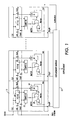
- Figure 1 shows a circuit for a one dimension string-match array. This diagram can be used to illustrate the basic concept of the proposed implementation.
- Register 10 in cell 11 is a storage element. When these cells are placed next to each other, these storage elements are connected together to form a right shift register.
- the input pixel stream (under compression) is shifted into the array from the left (InD port). These input pixels move from one cell to the next at every rising edge of the clock.
- the pixels stored in the shift register represent the previous string (history) and are used to match with the incoming pixel stream. Before each pixel is shifted into the array, it is used (CmpD port) to compare with each individual pixel (history) in the array at comparator 12. The matched result of each cell is sent out to the displacement encoder 13 for encoding and also stored in the cell flipflop 14 as a match marker. This array can process one pixel per clock cycle. If a match occurred on the previous cycle, the marker signal is asserted.
- the current matched result is sent out and also stored in the flipflop as a marker at the next rising edge of the clock. If a mismatch occurs, the output is a miss and the marker is negated at the following rising edge of the clock. From now on, the marker stays negated, the output stays mismatched and the compared result is ignored.
- the current matching operation is completed when all the DisplX (X is 1 to N) output signals were negated. The displacement value for the longest match is encapsulated within the DisplX signals of the previous cycle. The following gives the operation steps of this string-match array.
- the first pixel is matched with every pixel stored in the shift-register. This activity starts right after the rising edge of the clock.
- the InitPerMtch signal is asserted for one cycle. Effectively, this signal overrides the previous or initial marker value and enables the compared result from Comp[7:0] to be output and stored as a future marker directly.
- the Displacement Encoder scans the input signals from DisplO to DisplN for assertion. These signals are numbered from 0 (the leftmost) to N (the rightmost). The number that belongs to the signal that is found to be asserted first (in term of position) is latched as an output at the end of the clock cycle. This implies that the leftmost match is the most desirable one. This is because of the fact that it will give the smallest displacement value and as a result a shorter codeword is needed.
- the Displacement Encoder does find an assertion on the DisplX signals, the current matching operation will continue in the next clock cycle. In the next cycle, the InitPerMtch signal is not asserted. If the previous match of a cell is successful, the marker is asserted and the matched result from comp[7;0] 12 is again outputted and stored as a future marker. A miss in the previous cycle indicates that the pixel in the previous (to the right) cell has broken the matching sequence with the incoming pixel string. Once it is broken, the matches for the following pixels become meaningless and it is maintained in a miss-state by the marker signal until a new string-match operation is needed.
- the Displacement Encoder 13 If the Displacement Encoder 13 does not find an assertion on all the DisplX signals, the current string-match operation is completed.
- the displacement is given by the output of the displacement encoder on the previous cycle.
- the match length is given by the number of cycles that match did occur.
- a new string-match operation must be restarted within this current cycle. This can be done by asserting the InitPerMtch signal right after the displacement encoder has detected that there is no match on any of the DisplX signals.
- the Init signal is set to a 1, and is applied through OR gate 20 to one input of the AND gate 21. If the comparator shows a match on this cycle, another 1 is applied to the other input of AND gate 21. The resultant 1 output of gate 21 is sent out as the match signal, and the flip flop 22 is clocked on. Thereafter, as long as there is a match, the flipflop will stay on and continue to send out match signals.
- the 0 output of the comparator turns off the flipflop 22, and it will be disabled by its own output coupled through the OR gate 20 and AND gate 21 until the next Init signal is received.
- the displacement encoder 13 contains several simple logic circuits. One is a coder which uses the 4096 Displn lines as an input to generate a 12-bit number representing the "displacement" part of the output. Another is a counter which counts and outputs the number of matches, the "length”. Finally there is an OR circuit which detects when there is no match, for generating the Init signal.
- the one dimension array shown in Figure 1 provides an efficient scheme for transporting the pixel string and enables a high level of parallelism in performing the string-match. For example if there is 4096 cells, there will be 4096 possible strings to be searched for matching with the incoming string and all these searches are done at the same time. However in such a one dimension array with 4096 cells, the array must output 4096 DisplX signals. It will be a major problem to output that many lines from the array because these signal lines will use up a significant amount of space on the chip, and the Displacement Encoder will have a performance problem. When a big history buffer (large number of cells) is needed for a better compression ratio, a new implementation is needed.
- Figure 2 shows a two dimension (2D) string-match array example. This 2D circuit resolves the problems exhibited by the one dimensional circuit. To make this example easier to read and understand, a 4 x 4 cell array is drawn. The actual implementation can be extended to 64 x 64 (4096 cells) or higher.
- the cells 11 are repeated in both X and Y directions.
- the pixel stream is shifted into the upper left cell and output from the rightmost cell of the top row. This output feeds back into the leftmost cell of the second row and continues on to the rest of the cells.
- the DisplX signal is replaced by two match signals, the nVMtch and the nHMtch signal. Each of these signals is connected to the same signal of the other cells of the same row or of the same column to make a wired NOR gate.
- the matches that occur in the upper row supersede the ones below it.
- the row will be disabled by another upper row, which has a match occur in any one of its cells.
- the shortest displacement is selected if there are two matches of the same length in the same row. In this way, only one cell can pull a nVMtch signal low. If there is no nHMtch signal asserted at all, the Match will be negated and the Init signal will be asserted and changes the current cycle to become the first cycle of another string-match operation. In this case the locations of the matches of this first cycle are not available outside but are stored in the cells for the next cycle. This does not present any problem because if the longest match is only one pixel, the raw data will be used anyway.
- the displacement information for the longest match can be derived from the nHMtch and nVMtch signals.
- the upper 6 bits of the displacement value can be encoded from the nHMtch signals and the lower 6 bits can be encoded from the nVMtch signals.
- a problem with the cell logic of Figure 1 is that after a string of matches, during the next clock period, not only must the mismatch be detected soon enough to start an Init signal so that all of the cells can be reset, but also, it must be started soon enough so that all of the cells have enough time to compare the next input pixel.
- the path is so long that the circuit can not be used for high speed compression.
- the longest delay path for the Match circuit of Figure 1, when used in the two dimensional circuit of Figure 2, is from the rising edge of clock through the shift-register 10, the comparator 12, the AND gate 21, the wired NOR of the nHMtch signal and the wired NOR gate of the nVMtch signal. If an extremely large array is needed, one can break this path into two pipeline stages. This can be done by feeding the outputs of the nHMtch signals to a set of registers (one for each signal). The output of these registers drives the HMtch lines, thereby breaking the horizontal match detection and the vertical match detection in two pipelines stages. The cells must include logic to pipeline the vertical match information.
- the second longest path for the 2D circuit is from the rising edge of the clock through the shift-register 10, the comparator 12, the AND gate 21, the wired NOR of the nHMtch signal, the logic to generate the Init signal and the input of the Marker 14 flipflop.
- This path is only somewhat shorter than the nVMtch path.
- This path can also be broken into 2 pipeline stages by using the cell shown Figure 2. Since the VStrb is delayed by one cycle, in this new cell the Marker signal is used to drive the nVMtch signal. There are two horizontal match outputs. One (nHMtchO) delivers the same information as the nHMtch signal in the previous circuit. The other (nHMtchN) always delivers the match information of the second cycle of a new string-match operation.
- the Marker FF can either store the HMtchO or HMtchN information and this is selected by the Init signal.
- Figure 2 shows a 4 x 4 array example that uses this improved cell.
- the multiplexer 32 can select from either the AND 33 of the current comparison and the previous output, or the AND 34 of the current comparison and the previous comparison. This selection is determined by the match condition of the previous cycle. If the previous cycle produces a match in any cell, the previous output information is selected to be latched at the next rising edge of the clock. Otherwise the previous comparison information is selected. This leads to the fact that when a miss is detected, the Match signal is negated. This in turn asserts the Init signal and enables the Marker FF 30 in the cells to store the match information of a new (next) string-match operation. Also the nHMtchN, which carries the match information of the next string-match operation, is selected.
- This match information belongs to the second match cycle of the next string-match operation (not the first cycle). This is due to the fact that when a mismatch is detected on a cycle, one must immediately change this current cycle to the first cycle of a new string-match operation. However, by the time a mismatch is detected, it is too late to drive out any new information. Certainly, it is possible to add logic to do that but, as stated in the previous section, the match information of the first cycle has no value anyway. The performance of this circuit should be slightly less then two times faster than that of Figure 1.
- the #1 comparator goes negative, showing a mismatch, the init line is 0 so the multiplexer selects its upper input, and the comparator is 0 so the multiplexer 32 applies the 0 to the input of FF 30.
- the output Marker line goes low, causing the displacement encoder to generate an Init signal for one cycle.
Abstract
Description
- A circuit implementation for a substitutional compressor which uses a history buffer for storing the previous pixels and comparators for comparing the current pixel to every previous pixel in the history buffer.
- A substitutional compressor functions by replacing blocks of pixels with shorter references to earlier occurrences of identical blocks of pixels. For a numerical example, in the previous paragraph, the second occurrence of the words "history buffer" is repeated 126 spaces after the first occurrence in the word string (the "displacement"), and is a collection of 14 characters, counting the space between words, (the "length"). Thus, the second occurrence of "history buffer" can be replaced with the code word "126, 14".
- The algorithm always looks for the longest possible match. Thus, after finding a match for "history buffe", it will look for "history buffer" which it will find, and then "history buffer." (with a period after it) which it will not find (the previous occurrence had a following space). Thus, "history buffer" will be the longest possible match.
- The detailed algorithm can be found in a number of publications such as Edward R. Fiala and Daniel H. Greene, "Data Compression with Finite Windows" Communication of the ACM, April 1989,
Volume 32, Number 4, 490-505. Many other references are also given by this paper. - A typical history buffer would be 4K pixels long and the longest permissible match can be as much as 256 pixels, at up to eight bits per pixel. The algorithm can be implemented in software, but hardware would be preferred because of its higher speed. Content Addressable Memories (CAM) could be used. For example, 8-bit pixels could be loaded into 4K CAMs, and the current pixel could be compared to each. The next cycle would be to replace the oldest pixel with the current pixel, and use a new pixel for the next comparison. However, it would be inefficient to develop CAM hardware to perform this function. Using CAM's would require massive storage space and involve operation steps that are difficult to pipeline or parallel in hardware. The resulting device would be large and complex and its operation speed would not meet the requirements of high performance products. A completely new approach needs to be taken to resolve this problem.
- In accordance with the present invention, a circuit for compressing a string of words having one or more bits per word comprises:
- a first cell and a remaining number of cells, each comprising a means for storing a word, and a comparator, wherein all of said cells are coupled together so that all of the means for storing form a continuous register and are adapted to shift the words one word when a word is shifted into the means for storing of the first cell,
- each comparator coupled to the current word and the word stored in the means for storing in the same cell and adapted to compare the current word and the word stored in the means for storing, and to generate a match signal if there is a match, and to disable itself for detecting a match during the next clock cycle if there is no match, and
- an encoder coupled to every comparator and responsive to said match signals for generating an output code comprising the largest number of consecutive matches in a single cell and the displacement between the input and matching words.
-
- Instead of using a number of CAM's, this invention uses a number of cells in series, each cell having a register for storing one pixel, to implement the history buffer. Each previous pixel is loaded serially into the input end of the buffer, and all 4096 pixels are compared to the current pixel by the use of a comparator built into each cell. All cells that see a match continue to be enabled while any cell that sees a mismatch is disabled. If at least one match is seen, the current pixel is loaded into the history buffer, shifting all data to the right, and the next pixel is compared to all of the pixels contained in still-enabled cells in the history buffer. This process will continue until there is no match. In this case the last match will be the longest, and will be selected for coding. If there were two matches of equal length, the one with the shortest displacement is selected since the resultant code word for that one will be shorter. Then the cells are all reset, and the process starts again.
- One remaining problem with this arrangement in some cases is the large number of output lines, 4096 in this example, that must be run to the reset circuit. This may take up too much space on the chip. To reduce the number of lines, the cells may be organized into a two dimensional block, 64 by 64. Now, with some additional logic to determine the location of the cell with the best match, only 128 lines will be required.
- Some examples of circuits according to the invention will now be described with reference to the accompanying drawings, in which:-
- Figure 1 is a circuit diagram of a one dimensional history buffer and simplified cell logic;
- Figure 2 is a circuit diagram of a two dimensional history buffer and improved cell logic for higher speed operation; and,
- Figure 3 is a timing diagram of the cell logic of Figure 2.
-
- Figure 1 shows a circuit for a one dimension string-match array. This diagram can be used to illustrate the basic concept of the proposed implementation. Register 10 in
cell 11 is a storage element. When these cells are placed next to each other, these storage elements are connected together to form a right shift register. - The input pixel stream (under compression) is shifted into the array from the left (InD port). These input pixels move from one cell to the next at every rising edge of the clock. The pixels stored in the shift register represent the previous string (history) and are used to match with the incoming pixel stream. Before each pixel is shifted into the array, it is used (CmpD port) to compare with each individual pixel (history) in the array at
comparator 12. The matched result of each cell is sent out to thedisplacement encoder 13 for encoding and also stored in thecell flipflop 14 as a match marker. This array can process one pixel per clock cycle. If a match occurred on the previous cycle, the marker signal is asserted. The current matched result is sent out and also stored in the flipflop as a marker at the next rising edge of the clock. If a mismatch occurs, the output is a miss and the marker is negated at the following rising edge of the clock. From now on, the marker stays negated, the output stays mismatched and the compared result is ignored. The current matching operation is completed when all the DisplX (X is 1 to N) output signals were negated. The displacement value for the longest match is encapsulated within the DisplX signals of the previous cycle. The following gives the operation steps of this string-match array. - At the beginning of a string-match operation, the first pixel is matched with every pixel stored in the shift-register. This activity starts right after the rising edge of the clock.
- Also, at the beginning of a string-match operation, the InitPerMtch signal is asserted for one cycle. Effectively, this signal overrides the previous or initial marker value and enables the compared result from Comp[7:0] to be output and stored as a future marker directly.
- The Displacement Encoder scans the input signals from DisplO to DisplN for assertion. These signals are numbered from 0 (the leftmost) to N (the rightmost). The number that belongs to the signal that is found to be asserted first (in term of position) is latched as an output at the end of the clock cycle. This implies that the leftmost match is the most desirable one. This is because of the fact that it will give the smallest displacement value and as a result a shorter codeword is needed.
- If the Displacement Encoder does find an assertion on the DisplX signals, the current matching operation will continue in the next clock cycle. In the next cycle, the InitPerMtch signal is not asserted. If the previous match of a cell is successful, the marker is asserted and the matched result from comp[7;0] 12 is again outputted and stored as a future marker. A miss in the previous cycle indicates that the pixel in the previous (to the right) cell has broken the matching sequence with the incoming pixel string. Once it is broken, the matches for the following pixels become meaningless and it is maintained in a miss-state by the marker signal until a new string-match operation is needed.
- If the
Displacement Encoder 13 does not find an assertion on all the DisplX signals, the current string-match operation is completed. The displacement is given by the output of the displacement encoder on the previous cycle. The match length is given by the number of cycles that match did occur. A new string-match operation must be restarted within this current cycle. This can be done by asserting the InitPerMtch signal right after the displacement encoder has detected that there is no match on any of the DisplX signals. - A more detailed description of the operation of the logic for generating the match output signal is as follows. At the beginning of the next cycle after a mismatch ending a matched string, the Init signal is set to a 1, and is applied through
OR gate 20 to one input of the ANDgate 21. If the comparator shows a match on this cycle, another 1 is applied to the other input of ANDgate 21. The resultant 1 output ofgate 21 is sent out as the match signal, and the flip flop 22 is clocked on. Thereafter, as long as there is a match, the flipflop will stay on and continue to send out match signals. At the first mismatch, the 0 output of the comparator turns off the flipflop 22, and it will be disabled by its own output coupled through theOR gate 20 and ANDgate 21 until the next Init signal is received. - The
displacement encoder 13 contains several simple logic circuits. One is a coder which uses the 4096 Displn lines as an input to generate a 12-bit number representing the "displacement" part of the output. Another is a counter which counts and outputs the number of matches, the "length". Finally there is an OR circuit which detects when there is no match, for generating the Init signal. - The one dimension array shown in Figure 1 provides an efficient scheme for transporting the pixel string and enables a high level of parallelism in performing the string-match. For example if there is 4096 cells, there will be 4096 possible strings to be searched for matching with the incoming string and all these searches are done at the same time. However in such a one dimension array with 4096 cells, the array must output 4096 DisplX signals. It will be a major problem to output that many lines from the array because these signal lines will use up a significant amount of space on the chip, and the Displacement Encoder will have a performance problem. When a big history buffer (large number of cells) is needed for a better compression ratio, a new implementation is needed.
- Figure 2 shows a two dimension (2D) string-match array example. This 2D circuit resolves the problems exhibited by the one dimensional circuit. To make this example easier to read and understand, a 4 x 4 cell array is drawn. The actual implementation can be extended to 64 x 64 (4096 cells) or higher.
- In this 2D circuit the
cells 11 are repeated in both X and Y directions. The pixel stream is shifted into the upper left cell and output from the rightmost cell of the top row. This output feeds back into the leftmost cell of the second row and continues on to the rest of the cells. The DisplX signal is replaced by two match signals, the nVMtch and the nHMtch signal. Each of these signals is connected to the same signal of the other cells of the same row or of the same column to make a wired NOR gate. For achieving the shortest possible displacement codeword, the matches that occur in the upper row supersede the ones below it. The row will be disabled by another upper row, which has a match occur in any one of its cells. Also, as before, the shortest displacement is selected if there are two matches of the same length in the same row. In this way, only one cell can pull a nVMtch signal low. If there is no nHMtch signal asserted at all, the Match will be negated and the Init signal will be asserted and changes the current cycle to become the first cycle of another string-match operation. In this case the locations of the matches of this first cycle are not available outside but are stored in the cells for the next cycle. This does not present any problem because if the longest match is only one pixel, the raw data will be used anyway. - The displacement information for the longest match can be derived from the nHMtch and nVMtch signals. For a 64 x 64 array, the upper 6 bits of the displacement value can be encoded from the nHMtch signals and the lower 6 bits can be encoded from the nVMtch signals.
- With this 2D circuit, the signal lines needed to be brought out from the array is reduced from N to two times the square root of N where N is the total number of cells. The displacement encoder is naturally broken into two stages. The physical layout on the silicon can now be done efficiently.
- A problem with the cell logic of Figure 1 is that after a string of matches, during the next clock period, not only must the mismatch be detected soon enough to start an Init signal so that all of the cells can be reset, but also, it must be started soon enough so that all of the cells have enough time to compare the next input pixel. In the case of the logic of Figure 1, the path is so long that the circuit can not be used for high speed compression.
- The longest delay path for the Match circuit of Figure 1, when used in the two dimensional circuit of Figure 2, is from the rising edge of clock through the shift-
register 10, thecomparator 12, the ANDgate 21, the wired NOR of the nHMtch signal and the wired NOR gate of the nVMtch signal. If an extremely large array is needed, one can break this path into two pipeline stages. This can be done by feeding the outputs of the nHMtch signals to a set of registers (one for each signal). The output of these registers drives the HMtch lines, thereby breaking the horizontal match detection and the vertical match detection in two pipelines stages. The cells must include logic to pipeline the vertical match information. - Other than the nVMtch path, the second longest path for the 2D circuit is from the rising edge of the clock through the shift-
register 10, thecomparator 12, the ANDgate 21, the wired NOR of the nHMtch signal, the logic to generate the Init signal and the input of theMarker 14 flipflop. This path is only somewhat shorter than the nVMtch path. This path can also be broken into 2 pipeline stages by using the cell shown Figure 2. Since the VStrb is delayed by one cycle, in this new cell the Marker signal is used to drive the nVMtch signal. There are two horizontal match outputs. One (nHMtchO) delivers the same information as the nHMtch signal in the previous circuit. The other (nHMtchN) always delivers the match information of the second cycle of a new string-match operation. The Marker FF can either store the HMtchO or HMtchN information and this is selected by the Init signal. - Figure 2 shows a 4 x 4 array example that uses this improved cell. Notice that the
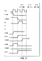
multiplexer 32 can select from either the AND 33 of the current comparison and the previous output, or the AND 34 of the current comparison and the previous comparison. This selection is determined by the match condition of the previous cycle. If the previous cycle produces a match in any cell, the previous output information is selected to be latched at the next rising edge of the clock. Otherwise the previous comparison information is selected. This leads to the fact that when a miss is detected, the Match signal is negated. This in turn asserts the Init signal and enables theMarker FF 30 in the cells to store the match information of a new (next) string-match operation. Also the nHMtchN, which carries the match information of the next string-match operation, is selected. This match information belongs to the second match cycle of the next string-match operation (not the first cycle). This is due to the fact that when a mismatch is detected on a cycle, one must immediately change this current cycle to the first cycle of a new string-match operation. However, by the time a mismatch is detected, it is too late to drive out any new information. Certainly, it is possible to add logic to do that but, as stated in the previous section, the match information of the first cycle has no value anyway. The performance of this circuit should be slightly less then two times faster than that of Figure 1. - This cell logic can be described with the use of the timing diagram of Figure 3. Assume that T=1, the
cell # 1 comparison is a mismatch after a series of matches, that thecell # 2 comparison is a match after a series of mismatches and that thecell # 3 comparison is an isolated match within a series of mismatches. In this situation, the mismatch ofcell # 1 should end one length and reset all of the other cells, the match ofcell # 2 should start a new series of matches, andcell # 3 should have no output since no attempt is made to compress an series with a length of 1. - At T=1 the #1 comparator goes negative, showing a mismatch, the init line is 0 so the multiplexer selects its upper input, and the comparator is 0 so the
multiplexer 32 applies the 0 to the input ofFF 30. When theFF 30 is clocked at T=2, the output Marker line goes low, causing the displacement encoder to generate an Init signal for one cycle. - In
cell # 2, at T=1 the comparator output goes 1. At T=2 the Init drives the multiplexer to select its lower input. The 1 is clocked throughFF 31 and the comparator output is still a 1, so a 1 is applied to the FF30 input. That is clocked onto the output line at T=3. - Notice that the
cell # 2 output goes high one clock cycle after thecell # 1 output went low. This is compensated for in thedisplacement encoder 13 by initializing the length counter to 1 instead of 0. - Finally, in
Cell # 3, the output is prevented from going high at T=3 because at T=2 Init is 1 which selects the lower mux input to apply it to FF30, and at T=2 the comparator is low so the mux must stay low. After a mismatch, the circuit will be enabled only if there are two matches in series At T=1 and T=2. - Throughout this discussion, the term "pixel" was used and 8 bit words were assumed. However, it is intended that this compression circuit and method is usable for digital data of any kind and words of any size. The only requirement is that the data is formed into a series of words of fixed length.
Claims (7)
- A circuit for compressing a string of words having one or more bits per word comprising:a first cell and a remaining number of cells, each comprising a means for storing a word, and a comparator, wherein all of said cells are coupled together so that all of the means for storing form a continuous register and are adapted to shift the words one word when a word is shifted into the means for storing of the first cell,each comparator coupled to the current word and the word stored in the means for storing in the same cell and adapted to compare the current word and the word stored in the means for storing, and to generate a match signal if there is a match, and to disable itself for detecting a match during the next clock cycle if there is no match, andan encoder coupled to every comparator and responsive to said match signals for generating an output code comprising the largest number of consecutive matches in a single cell and the displacement between the input and matching words.
- The circuit of claim 1, wherein the encoder will output the code after the detection of a non-match in the cell that generated the longest number of matches on the previous clock, and initialize the circuit to compare the current word with the contents of every means for storing on the same clock cycle.
- The circuit of claim 1 or claim 2, wherein the cells are arranged into rows and columns, with an output line for each row and each column of cells for coupling all of the cells in each row and each column on an output line to the encoder, and wherein, after the detection of a non-match after two or more consecutive matches, if there are cells in more than one row with the same largest number of matches, the match generated by a cell in a previous row will be selected to output the code, and if there is more than one cell in a row with the same number of matches, the match generated by a previous cell will be selected to output the code.
- A circuit for compressing a string of words comprising:a first cell and a remaining number of cells, each cell comprising a means for storing a word and a comparator, wherein all of said cells are coupled together so that all of the means for storing form a continuous register and are adapted to shift the words one word when a current word is shifted into said first means for storing on each clock cycle,each comparator coupled to the current input pixel and the means for storing in the same cell, and adapted to compare the current pixel and the pixel stored in the means for storing on each clock cycle, and to generate a match signal when there is a match, and to disable itself when there is no match, andan encoder responsive to the first clock after the end of a continuous number of match signals for generating an output code comprising the largest number of consecutive matches in a single cell and the displacement of the cell that detected the matches or the lowest numbered cell that detected the matches if there were more than one, and for generating an initializing signal to enable all of the comparators that were disabled.
- The circuit of claim 4, wherein the cells are arranged in rows and columns and wherein the encoder is coupled to all of the cells in each row by one line and all of the cells in each column by one line.
- The method of compressing a string of words comprising the steps of:a. comparing a current word with a number of previous words,b. if there is a match between the current word and a previous word, then compare the next current word with the word after the previous word,c. repeat step b. until there is no match, andd. output the number of matches found and the displacement of words between the first current word and the first matching previous word.
- The method of compressing a string of words comprising the steps of:a. comparing a current word with a number of previous words,b. if there is a match between the current word and more than one previous word, then compare the next current word with the word after each previous word that matched,c. repeat step b. to determine the largest number of consecutive matches, andd. if the largest consecutive number of matches occurred in a single cell, output the number of consecutive matches found and the displacement of words separating the first current word and the closest matching previous word, ore. if the largest consecutive number of matches occurred in more than one cell, output the number of consecutive matches found and the number of words separating the first current word and the first matching previous word.
Applications Claiming Priority (2)
| Application Number | Priority Date | Filing Date | Title |
|---|---|---|---|
| US937554 | 1997-09-25 | ||
| US08/937,554 US5930790A (en) | 1997-09-25 | 1997-09-25 | String-match array for substitutional compression |
Publications (3)
| Publication Number | Publication Date |
|---|---|
| EP0907146A2 true EP0907146A2 (en) | 1999-04-07 |
| EP0907146A3 EP0907146A3 (en) | 2000-03-01 |
| EP0907146B1 EP0907146B1 (en) | 2004-05-06 |
Family
ID=25470081
Family Applications (1)
| Application Number | Title | Priority Date | Filing Date |
|---|---|---|---|
| EP98307195A Expired - Lifetime EP0907146B1 (en) | 1997-09-25 | 1998-09-07 | Data compression apparatus using matching string |
Country Status (4)
| Country | Link |
|---|---|
| US (1) | US5930790A (en) |
| EP (1) | EP0907146B1 (en) |
| JP (1) | JP3026962B2 (en) |
| DE (1) | DE69823607T2 (en) |
Cited By (1)
| Publication number | Priority date | Publication date | Assignee | Title |
|---|---|---|---|---|
| WO2002019535A1 (en) * | 2000-08-29 | 2002-03-07 | Koninklijke Philips Electronics N.V. | Hardware implementation of a compression algorithm |
Families Citing this family (18)
| Publication number | Priority date | Publication date | Assignee | Title |
|---|---|---|---|---|
| US6118682A (en) * | 1998-07-07 | 2000-09-12 | Vlsi Technology, Inc. | Method and apparatus for reading multiple matched addresses |
| US6813680B1 (en) | 2000-06-14 | 2004-11-02 | Netlogic Microsystems, Inc. | Method and apparatus for loading comparand data into a content addressable memory system |
| US6542391B2 (en) * | 2000-06-08 | 2003-04-01 | Netlogic Microsystems, Inc. | Content addressable memory with configurable class-based storage partition |
| US6799243B1 (en) | 2000-06-14 | 2004-09-28 | Netlogic Microsystems, Inc. | Method and apparatus for detecting a match in an intra-row configurable cam system |
| US6751701B1 (en) | 2000-06-14 | 2004-06-15 | Netlogic Microsystems, Inc. | Method and apparatus for detecting a multiple match in an intra-row configurable CAM system |
| US6795892B1 (en) | 2000-06-14 | 2004-09-21 | Netlogic Microsystems, Inc. | Method and apparatus for determining a match address in an intra-row configurable cam device |
| US6757779B1 (en) | 1999-09-23 | 2004-06-29 | Netlogic Microsystems, Inc. | Content addressable memory with selectable mask write mode |
| US6252789B1 (en) * | 2000-06-14 | 2001-06-26 | Netlogic Microsystems, Inc. | Inter-row configurability of content addressable memory |
| US6243281B1 (en) | 2000-06-14 | 2001-06-05 | Netlogic Microsystems, Inc. | Method and apparatus for accessing a segment of CAM cells in an intra-row configurable CAM system |
| US6560670B1 (en) | 2000-06-14 | 2003-05-06 | Netlogic Microsystems, Inc. | Inter-row configurability of content addressable memory |
| US6246601B1 (en) | 2000-06-14 | 2001-06-12 | Netlogic Microsystems, Inc. | Method and apparatus for using an inter-row configurable content addressable memory |
| CN1559072A (en) * | 2001-09-30 | 2004-12-29 | ÷ķ�����������ι�˾ | Reverse searching system and method |
| JP4164257B2 (en) * | 2001-12-06 | 2008-10-15 | キヤノン株式会社 | Image processing apparatus, image processing method, program, and storage medium |
| CN100437549C (en) * | 2002-09-04 | 2008-11-26 | 珠海市零壹网络标准数据有限责任公司 | Computer adaption system and method for multivariated information of supply and demand |
| CA2461638A1 (en) * | 2004-03-22 | 2005-09-22 | Impatica Inc. | Mobile multimedia delivery |
| US7937510B1 (en) | 2005-02-01 | 2011-05-03 | Altera Corporation | Lempel Ziv compression architecture |
| US7109895B1 (en) * | 2005-02-01 | 2006-09-19 | Altera Corporation | High performance Lempel Ziv compression architecture |
| AU2005248949B2 (en) * | 2005-12-23 | 2010-04-01 | Canon Kabushiki Kaisha | Efficient Halftone Image Compression |
Citations (6)
| Publication number | Priority date | Publication date | Assignee | Title |
|---|---|---|---|---|
| WO1989001653A1 (en) * | 1987-08-20 | 1989-02-23 | Davin Computer Corporation | Parallel string processor and method for a minicomputer |
| US5003307A (en) * | 1989-01-13 | 1991-03-26 | Stac, Inc. | Data compression apparatus with shift register search means |
| EP0568305A2 (en) * | 1992-04-27 | 1993-11-03 | Integrated Information Technology, Inc., | Data compression |
| US5369605A (en) * | 1993-07-07 | 1994-11-29 | Dell Usa, L.P. | Incremental search content addressable memory for increased data compression efficiency |
| US5467319A (en) * | 1993-09-20 | 1995-11-14 | Codex, Corp. | CAM array and method of laying out the same |
| US5532693A (en) * | 1994-06-13 | 1996-07-02 | Advanced Hardware Architectures | Adaptive data compression system with systolic string matching logic |
Family Cites Families (5)
| Publication number | Priority date | Publication date | Assignee | Title |
|---|---|---|---|---|
| US3648254A (en) * | 1969-12-31 | 1972-03-07 | Ibm | High-speed associative memory |
| US5179378A (en) * | 1991-07-30 | 1993-01-12 | University Of South Florida | Method and apparatus for the compression and decompression of data using Lempel-Ziv based techniques |
| US5373290A (en) * | 1991-09-25 | 1994-12-13 | Hewlett-Packard Corporation | Apparatus and method for managing multiple dictionaries in content addressable memory based data compression |
| US5499382A (en) * | 1993-09-20 | 1996-03-12 | Nusinov; Eugene B. | Circuit and method of bit-packing and bit-unpacking using a barrel shifter |
| US5828593A (en) * | 1996-07-11 | 1998-10-27 | Northern Telecom Limited | Large-capacity content addressable memory |
-
1997
- 1997-09-25 US US08/937,554 patent/US5930790A/en not_active Expired - Lifetime
-
1998
- 1998-09-07 EP EP98307195A patent/EP0907146B1/en not_active Expired - Lifetime
- 1998-09-07 DE DE69823607T patent/DE69823607T2/en not_active Expired - Lifetime
- 1998-09-18 JP JP10264247A patent/JP3026962B2/en not_active Expired - Fee Related
Patent Citations (6)
| Publication number | Priority date | Publication date | Assignee | Title |
|---|---|---|---|---|
| WO1989001653A1 (en) * | 1987-08-20 | 1989-02-23 | Davin Computer Corporation | Parallel string processor and method for a minicomputer |
| US5003307A (en) * | 1989-01-13 | 1991-03-26 | Stac, Inc. | Data compression apparatus with shift register search means |
| EP0568305A2 (en) * | 1992-04-27 | 1993-11-03 | Integrated Information Technology, Inc., | Data compression |
| US5369605A (en) * | 1993-07-07 | 1994-11-29 | Dell Usa, L.P. | Incremental search content addressable memory for increased data compression efficiency |
| US5467319A (en) * | 1993-09-20 | 1995-11-14 | Codex, Corp. | CAM array and method of laying out the same |
| US5532693A (en) * | 1994-06-13 | 1996-07-02 | Advanced Hardware Architectures | Adaptive data compression system with systolic string matching logic |
Cited By (1)
| Publication number | Priority date | Publication date | Assignee | Title |
|---|---|---|---|---|
| WO2002019535A1 (en) * | 2000-08-29 | 2002-03-07 | Koninklijke Philips Electronics N.V. | Hardware implementation of a compression algorithm |
Also Published As
| Publication number | Publication date |
|---|---|
| DE69823607T2 (en) | 2005-04-21 |
| JPH11163735A (en) | 1999-06-18 |
| EP0907146A3 (en) | 2000-03-01 |
| US5930790A (en) | 1999-07-27 |
| DE69823607D1 (en) | 2004-06-09 |
| JP3026962B2 (en) | 2000-03-27 |
| EP0907146B1 (en) | 2004-05-06 |
Similar Documents
| Publication | Publication Date | Title |
|---|---|---|
| EP0907146B1 (en) | Data compression apparatus using matching string | |
| CA2007168C (en) | Variable length string matcher | |
| US5532693A (en) | Adaptive data compression system with systolic string matching logic | |
| US5440753A (en) | Variable length string matcher | |
| KR100702428B1 (en) | Method and circuit for data compression | |
| US5696507A (en) | Method and apparatus for decoding variable length code | |
| US6334123B1 (en) | Index relational processor | |
| US20010051941A1 (en) | Searching method of block sorting lossless compressed data, and encoding method suitable for searching data in block sorting lossless compressed data | |
| US5136289A (en) | Dictionary searching system | |
| US20090058693A1 (en) | System and method for huffman decoding within a compression engine | |
| JPH08274649A (en) | Data compression equipment using lempel-ziv type algorithm | |
| US5177622A (en) | Method and apparatus for detecting run length of two successive pixels and subjecting run length to universal coding | |
| Lee et al. | $2^{n} $ pattern run-length for test data compression | |
| US6348881B1 (en) | Efficient hardware implementation of a compression algorithm | |
| US20160372179A1 (en) | Hardware-based compression ratio improvement | |
| US5694125A (en) | Sliding window with big gap data compression system | |
| US7764205B2 (en) | Decompressing dynamic huffman coded bit streams | |
| US6320523B1 (en) | Method and apparatus for reducing the time required for compressing data | |
| EP1214792B1 (en) | Method and apparatus for reducing the time required for decompressing data | |
| US6947604B2 (en) | Method and hardware to implement two-dimensional compression | |
| US6392571B1 (en) | String search apparatus and method for data compression | |
| Kuo et al. | Design of a low power architecture for CABAC encoder in H. 264 | |
| EP0411691B1 (en) | Memory architecture and circuit for hashing | |
| JP2002237754A (en) | Variable length decoding device and its method | |
| Lee et al. | A generalized prediction method for modified memory-based high throughput VLC decoder design |
Legal Events
| Date | Code | Title | Description |
|---|---|---|---|
| PUAI | Public reference made under article 153(3) epc to a published international application that has entered the european phase |
Free format text: ORIGINAL CODE: 0009012 |
|
| AK | Designated contracting states |
Kind code of ref document: A2 Designated state(s): DE FR GB |
|
| AX | Request for extension of the european patent |
Free format text: AL;LT;LV;MK;RO;SI |
|
| PUAL | Search report despatched |
Free format text: ORIGINAL CODE: 0009013 |
|
| AK | Designated contracting states |
Kind code of ref document: A3 Designated state(s): AT BE CH CY DE DK ES FI FR GB GR IE IT LI LU MC NL PT SE |
|
| AX | Request for extension of the european patent |
Free format text: AL;LT;LV;MK;RO;SI |
|
| 17P | Request for examination filed |
Effective date: 20000901 |
|
| AKX | Designation fees paid |
Free format text: DE FR GB |
|
| 17Q | First examination report despatched |
Effective date: 20030116 |
|
| GRAP | Despatch of communication of intention to grant a patent |
Free format text: ORIGINAL CODE: EPIDOSNIGR1 |
|
| GRAS | Grant fee paid |
Free format text: ORIGINAL CODE: EPIDOSNIGR3 |
|
| GRAA | (expected) grant |
Free format text: ORIGINAL CODE: 0009210 |
|
| AK | Designated contracting states |
Kind code of ref document: B1 Designated state(s): DE FR GB |
|
| REG | Reference to a national code |
Ref country code: GB Ref legal event code: FG4D |
|
| REF | Corresponds to: |
Ref document number: 69823607 Country of ref document: DE Date of ref document: 20040609 Kind code of ref document: P |
|
| ET | Fr: translation filed | ||
| PLBE | No opposition filed within time limit |
Free format text: ORIGINAL CODE: 0009261 |
|
| STAA | Information on the status of an ep patent application or granted ep patent |
Free format text: STATUS: NO OPPOSITION FILED WITHIN TIME LIMIT |
|
| 26N | No opposition filed |
Effective date: 20050208 |
|
| REG | Reference to a national code |
Ref country code: FR Ref legal event code: PLFP Year of fee payment: 19 |
|
| PGFP | Annual fee paid to national office [announced via postgrant information from national office to epo] |
Ref country code: DE Payment date: 20160823 Year of fee payment: 19 Ref country code: GB Payment date: 20160825 Year of fee payment: 19 |
|
| PGFP | Annual fee paid to national office [announced via postgrant information from national office to epo] |
Ref country code: FR Payment date: 20160822 Year of fee payment: 19 |
|
| REG | Reference to a national code |
Ref country code: DE Ref legal event code: R119 Ref document number: 69823607 Country of ref document: DE |
|
| GBPC | Gb: european patent ceased through non-payment of renewal fee |
Effective date: 20170907 |
|
| REG | Reference to a national code |
Ref country code: FR Ref legal event code: ST Effective date: 20180531 |
|
| PG25 | Lapsed in a contracting state [announced via postgrant information from national office to epo] |
Ref country code: GB Free format text: LAPSE BECAUSE OF NON-PAYMENT OF DUE FEES Effective date: 20170907 Ref country code: DE Free format text: LAPSE BECAUSE OF NON-PAYMENT OF DUE FEES Effective date: 20180404 |
|
| PG25 | Lapsed in a contracting state [announced via postgrant information from national office to epo] |
Ref country code: FR Free format text: LAPSE BECAUSE OF NON-PAYMENT OF DUE FEES Effective date: 20171002 |