EP0898220A1 - Electronic apparatus with improved heatsink arrangement - Google Patents
Electronic apparatus with improved heatsink arrangement Download PDFInfo
- Publication number
- EP0898220A1 EP0898220A1 EP97410090A EP97410090A EP0898220A1 EP 0898220 A1 EP0898220 A1 EP 0898220A1 EP 97410090 A EP97410090 A EP 97410090A EP 97410090 A EP97410090 A EP 97410090A EP 0898220 A1 EP0898220 A1 EP 0898220A1
- Authority
- EP
- European Patent Office
- Prior art keywords
- heatsink
- housing
- vent structure
- wall
- electronic apparatus
- Prior art date
- Legal status (The legal status is an assumption and is not a legal conclusion. Google has not performed a legal analysis and makes no representation as to the accuracy of the status listed.)
- Granted
Links
Images


Classifications
-
- G—PHYSICS
- G06—COMPUTING; CALCULATING OR COUNTING
- G06F—ELECTRIC DIGITAL DATA PROCESSING
- G06F1/00—Details not covered by groups G06F3/00 - G06F13/00 and G06F21/00
- G06F1/16—Constructional details or arrangements
- G06F1/20—Cooling means
Definitions
- This invention relates to the cooling of electronic apparatus and, more particularly, to electronic apparatus having a heatsink arrangement which is effective in more than one operating orientation.
- the invention finds particular, though not necessarily exclusive, application to personal computers which may be operated in either a desktop or tower configuration.
- the processors and other components of modern personal computers generate significant amounts of heat in operation and therefore require cooling.
- a fan is provided in the computer housing which provides a forced air flow within the housing.
- Individual components, such as the processor chip itself, which generate significant amounts of heat can be provided with heatsinks for dissipating heat generated by the component.
- the processor chip itself is cooled by the use of a fan heatsink, in which a fan is mounted on a heatsink on the processor package to blow air across the heatsink.
- the fan Whilst the use of a forced air flow can provide effective cooling and has the advantage that it can allow the computer to operate in more than one orientation, the fan necessarily generates undesirable noise.
- the noise generated is directly related to the speed of the fan and consequently to the degree of cooling provided by the forced air flow.
- the reliability of the fan may be reduced with higher fan speeds. For the above reasons, in the design of such systems it is desirable to try to reduce the speed of the fan or eliminate the use of a forced air flow entirely.
- the object of this invention is to provide an improved cooling arrangement for a personal computer and which, in particular, allows the computer to be operated in more than one operating orientation.
- this object is achieved by electronic apparatus comprising an electronic component which in use generates heat and a heatsink mounted within a housing having a thermal path to the electronic component.
- the heatsink comprises formations for generating by natural convection a cooling airflow for dissipating heat from the electronic component.
- Neighbouring first and second walls of the housing each comprise a vent structure and the formations of the heatsink define one or more oblique paths from the vent structure in the first wall across the heatsink to the vent structure in the second wall so that in at least a first operating orientation the cooling airflow generated by the heatsink passes from the vent structure in the first wall across the heatsink to the vent structure of the second wall and in at least a second operating orientation the cooling airflow generated by the heatsink passes from the vent structure in the second wall across the heatsink to the vent structure of the first wall.
- the apparatus may be designed to work equally well in more than one operating orientation.
- the invention is therefore particularly suitable for a personal computer system unit which may be used in either desktop and tower operating orientations, although the application of the invention to other types of electronic apparatus with a similar requirement is not excluded. Even if, for other reasons, any particular model of personal computer may not actually be usable in both orientations, the invention is still of advantage to computer manufacturers since it allows them to use common components between different models adapted for desktop and tower orientations, thereby reducing manufacturing cost.
- the electronic component may be the computer processor chip itself which is a major source of heat.
- the heatsink comprises a baseplate disposed to as to cut off the corner at which the first and second walls meet so that the cooling airflow generated by the heatsink is separated from the air within the rest of the interior of the housing.
- the formations can comprise a plurality of fins that are perpendicular to the first and second walls.
- the heatsink has the form of an elongate triangular prism having a plurality of slots along one edge.
- the heatsink can be mounted in the housing so that the edge that is slotted is adjacent and parallel to the corner at which the first and second walls meet.
- the thermal path includes one or more heat pipes.
- the apparatus may also include a plurality of other electronic components mounted within the housing and a fan mounted on or within the housing for providing a forced airflow to cool said other electronic components.
- the above described arrangement has the advantage that the forced airflow does not need to remove heat from the, or those, components which have a heat path to the heatsink. Therefore, the required fan speed and consequently the noise generated by the apparatus, can be lower than would otherwise be the case.
- Figs 1 and 2 show exploded perspective views of a personal computer system unit 100 from the front and rear respectively.
- System unit 100 has an improved processor cooling arrangement and which is operable in a number of different operating orientations.
- Computer system unit 100 has a generally cuboid housing made up of three-sided cover 110 and chassis unit 120 .
- Cover 110 is removably mounted in an appropriate manner on chassis unit 120 .
- motherboard 130 Mounted within the housing on the chassis unit 120 is motherboard 130 upon which is mounted the computer processor package 140 .
- processor 140 of one of the Pentium (trademark) II family of processors available from Intel Corporation.
- processor packages are orthogonally mounted on the motherboard using an edge connector and can in use generate around 40 watts of thermal power.
- motherboard 130 many other electronic components (not shown) are also mounted on motherboard 130 .
- other functional components of the computer which are not directly relevant to an understanding of the present invention, such as hard and floppy disk drives and a power supply, are of course also mounted on chassis unit 120 .
- Processor package 140 is cooled by corner heatsink 150 which is mounted within the housing on chassis unit 120 .
- Heatsink 150 is made of cast aluminium and is shaped as an elongate triangular prism having a plurality of slots along one edge which form a series of parallel fins 190 upstanding from an obliquely disposed base plate 210 . Fins 190 generate a cooling airflow by natural convection.
- the top surface 160 and side wall 170 of the cover 110 comprise vent structures 180 which are symetrically disposed adjacent corner 165 .
- Fig 3 is a cutaway view of the top corner of the housing showing the disposition of heatsink 150 in relation to the vents 180 in cover 110 .
- the direction of the convective airflow depends on the operating orientation of the computer.
- heatsink 150 is mounted on chassis unit 120 so that the slotted edge is adjacent and parallel to the corner 165 formed by top surface 160 and side wall 170 of cover 110 .
- Baseplate 210 cuts off corner 165 so as to separate the convective airflow generated by Fins 190 from the air in the rest of the interior of the housing.
- heat pipes 200 provide a thermal path from processor 140 to heatsink 150 .
- a heat pipe is known type of passive device for efficiently transferring heat from a heat source to a heat sink and generally comprises a vacuum-tight elongate vessel which is evacuated and partially filled with a minute amount of water or other working fluid.
- a wick structure is provided inside the pipe.
- the evaporator As heat enters the device at one end, known as the evaporator, the fluid is vaporized creating a pressure gradient in the pipe. This forces the vapor to flow along the pipe to the other end of the pipe, known as the condenser, where it condenses, giving up its latent heat of vaporization.
- the working fluid is then returned to the evaporator by capillary action in the wick. Heat is thereby transferred from the evaporator to the condenser.
- a variety of heat pipe products are commercially available from a number of suppliers.
- the evaporators of heat pipes 200 are clamped to a mounting block 300 which is in thermal contact with a thermal plate provided on processor package 140 .
- the condensors of heat pipes 200 are in thermal contact with the heatsink 150 .
- two heat pipes are shown connecting processor 140 and heatsink 150 . It will be appreciated that the number of heat pipes required depends upon the heat transfer capacity of the heat pipes and other design considerations, such as the flexibility of the pipes.
- the computer 100 also includes fan 195 mounted to the front of chassis unit 120 .
- Fan 195 draws air in through openings provided in the front of the chassis (shown in Fig 1 in a partly cut-away view) to provide a forced airflow within the housing to cool other electronic components mounted on motherboard 130 . Due to the triangular form of heatsink 150 and its position in the corner of the housing, the forced airflow generated by fan 195 is separated from the convective airflow generated by heatsink 150 by baseplate 210 .
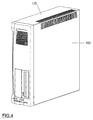
- the computer of this embodiment has three possible operating positions as shown in Figs 4, 5 and 6.
- Fig 4 shows a first tower position in which the corner heatsink is positioned at one of the top corners of the computer. In this case a cooling airflow passes from the openings in surface 160 of cover 110 across the heatsink to the openings of side wall 170 of cover 110 .
- Fig 5 shows a second tower position in which the corner heatsink is positioned at one of the bottom corners of the computer.
- the housing is provided with feet 500 which allow an airflow to enter the openings in side wall 170 . The airflow then passes across the heatsink and exits through the openings in surface 160 .
- Fig 6 shows a desktop position for the computer in which the cooling airflow passes through the openings in side wall 170 , across the heatsink and out through the openings in top surface 160 .
Abstract
Description
- This invention relates to the cooling of electronic apparatus and, more particularly, to electronic apparatus having a heatsink arrangement which is effective in more than one operating orientation. The invention finds particular, though not necessarily exclusive, application to personal computers which may be operated in either a desktop or tower configuration.
- The processors and other components of modern personal computers generate significant amounts of heat in operation and therefore require cooling. Generally, a fan is provided in the computer housing which provides a forced air flow within the housing. Individual components, such as the processor chip itself, which generate significant amounts of heat can be provided with heatsinks for dissipating heat generated by the component. Sometimes, the processor chip itself is cooled by the use of a fan heatsink, in which a fan is mounted on a heatsink on the processor package to blow air across the heatsink.
- Whilst the use of a forced air flow can provide effective cooling and has the advantage that it can allow the computer to operate in more than one orientation, the fan necessarily generates undesirable noise. The noise generated is directly related to the speed of the fan and consequently to the degree of cooling provided by the forced air flow. Furthermore, the reliability of the fan may be reduced with higher fan speeds. For the above reasons, in the design of such systems it is desirable to try to reduce the speed of the fan or eliminate the use of a forced air flow entirely.
- In another known cooling arrangement used in various types of electronic apparatus, at least part of the excess heat is transferred from within a housing to a heat sink mounted on the exterior of the housing which generates a cooling airflow by convection. For safety or aesthetic reasons such an external heatsink would normally be mounted to the rear of the housing, at least in products destined for use in offices or homes.
- One problem with this arrangement is that such convective heatsinks usually comprise a set of parallel fins and will only operate effectively with the fins vertical. Such a finned heatsink mounted to the rear of a typical personal computer system unit would not allow the unit to operate correctly both in a desktop orientation and in a tower orientation, the two most common operating configurations for personal computers. It will be understood that in general, in a desktop configuration a computer system unit housing is wider than it is tall, so that a computer display may be placed on top of the housing. In a tower configuration, a computer system unit housing is taller than it is wide so that it may conveniently be placed on the floor beside a desk, the associated display being placed on the desk separate from the system unit.
- The object of this invention is to provide an improved cooling arrangement for a personal computer and which, in particular, allows the computer to be operated in more than one operating orientation.
- In brief, this object is achieved by electronic apparatus comprising an electronic component which in use generates heat and a heatsink mounted within a housing having a thermal path to the electronic component. The heatsink comprises formations for generating by natural convection a cooling airflow for dissipating heat from the electronic component. Neighbouring first and second walls of the housing each comprise a vent structure and the formations of the heatsink define one or more oblique paths from the vent structure in the first wall across the heatsink to the vent structure in the second wall so that in at least a first operating orientation the cooling airflow generated by the heatsink passes from the vent structure in the first wall across the heatsink to the vent structure of the second wall and in at least a second operating orientation the cooling airflow generated by the heatsink passes from the vent structure in the second wall across the heatsink to the vent structure of the first wall.
- Since the vents in the walls of the housing and the disposition of the heatsink allow the convective airflow generated by the heatsink to pass in more than one direction across the heatsink according to the orientation of the housing, the apparatus may be designed to work equally well in more than one operating orientation. The invention is therefore particularly suitable for a personal computer system unit which may be used in either desktop and tower operating orientations, although the application of the invention to other types of electronic apparatus with a similar requirement is not excluded. Even if, for other reasons, any particular model of personal computer may not actually be usable in both orientations, the invention is still of advantage to computer manufacturers since it allows them to use common components between different models adapted for desktop and tower orientations, thereby reducing manufacturing cost.
- Suitably, in this application, the electronic component may be the computer processor chip itself which is a major source of heat.
- Preferably, the heatsink comprises a baseplate disposed to as to cut off the corner at which the first and second walls meet so that the cooling airflow generated by the heatsink is separated from the air within the rest of the interior of the housing. This arrangement provides the advantages of an external heatsink but without the potential safety problems and aesthetic drawbacks associated with external heatsinks.
- The formations can comprise a plurality of fins that are perpendicular to the first and second walls.
- In a preferred embodiment, the heatsink has the form of an elongate triangular prism having a plurality of slots along one edge. In this case, the heatsink can be mounted in the housing so that the edge that is slotted is adjacent and parallel to the corner at which the first and second walls meet. This arrangement is particularly space efficient and is advantageous especially for apparatus destined for home or office use, where it is usually desirable to reduce the overall size of the housing not only for aesthetic reasons and user convenience but also in order to reduce the cost of the housing and other associated elements, such as electromagnetic shielding structures or the like.
- In a particularly preferred implementation, the thermal path includes one or more heat pipes.
- In practice and in particular in the application of the invention to personal computers, the apparatus may also include a plurality of other electronic components mounted within the housing and a fan mounted on or within the housing for providing a forced airflow to cool said other electronic components. In this case, the above described arrangement has the advantage that the forced airflow does not need to remove heat from the, or those, components which have a heat path to the heatsink. Therefore, the required fan speed and consequently the noise generated by the apparatus, can be lower than would otherwise be the case.
- A personal computer system unit embodying the invention will now be described, by way of non-limiting example, with reference to the accompanying diagrammatic drawings, in which:
- Figure 1 is an exploded partly cut-away front perspective view of a personal computer system unit;
- Figure 2 is an exploded rear perspective view of the personal computer system unit of Fig 1;
- Figure 3 is a partly cut-away view of the heatsink arrangement in the system unit of Figs 1 & 2;
- Figures 4, 5 & 6 illustrate three different operating positions for the personal computer system unit.
-
- Figs 1 and 2 show exploded perspective views of a personal
computer system unit 100 from the front and rear respectively.System unit 100 has an improved processor cooling arrangement and which is operable in a number of different operating orientations. -
Computer system unit 100 has a generally cuboid housing made up of three-sided cover 110 andchassis unit 120.Cover 110 is removably mounted in an appropriate manner onchassis unit 120. Apart from the cooling arrangements described below, the general configuration and functioning ofsystem unit 100 is conventional and need not be described in detail here. Mounted within the housing on thechassis unit 120 ismotherboard 130 upon which is mounted thecomputer processor package 140. In this embodiment,processor 140 of one of the Pentium (trademark) II family of processors available from Intel Corporation. Such processor packages are orthogonally mounted on the motherboard using an edge connector and can in use generate around 40 watts of thermal power. - As is conventional, many other electronic components (not shown) are also mounted on
motherboard 130. In addition, other functional components of the computer which are not directly relevant to an understanding of the present invention, such as hard and floppy disk drives and a power supply, are of course also mounted onchassis unit 120. -
Processor package 140 is cooled bycorner heatsink 150 which is mounted within the housing onchassis unit 120. Heatsink 150 is made of cast aluminium and is shaped as an elongate triangular prism having a plurality of slots along one edge which form a series ofparallel fins 190 upstanding from an obliquely disposedbase plate 210. Fins 190 generate a cooling airflow by natural convection. - The
top surface 160 andside wall 170 of thecover 110 comprisevent structures 180 which are symetrically disposedadjacent corner 165. Fig 3 is a cutaway view of the top corner of the housing showing the disposition ofheatsink 150 in relation to thevents 180 incover 110. The airflow generated byheatsink 150 to pass either from the vent inside wall 170 across the heatsink to the vent in thetop surface 160 as indicated by the arrow in Fig 3 or in the opposite direction from the vent in thetop surface 160 across the heatsink to the vent ofside wall 170. The direction of the convective airflow depends on the operating orientation of the computer. - As can be seen in Fig 3,
heatsink 150 is mounted onchassis unit 120 so that the slotted edge is adjacent and parallel to thecorner 165 formed bytop surface 160 andside wall 170 ofcover 110. Baseplate 210 cuts offcorner 165 so as to separate the convective airflow generated by Fins 190 from the air in the rest of the interior of the housing. - As can be seen in Figs 2 and 3,
heat pipes 200 provide a thermal path fromprocessor 140 toheatsink 150. A heat pipe is known type of passive device for efficiently transferring heat from a heat source to a heat sink and generally comprises a vacuum-tight elongate vessel which is evacuated and partially filled with a minute amount of water or other working fluid. A wick structure is provided inside the pipe. As heat enters the device at one end, known as the evaporator, the fluid is vaporized creating a pressure gradient in the pipe. This forces the vapor to flow along the pipe to the other end of the pipe, known as the condenser, where it condenses, giving up its latent heat of vaporization. The working fluid is then returned to the evaporator by capillary action in the wick. Heat is thereby transferred from the evaporator to the condenser. A variety of heat pipe products are commercially available from a number of suppliers. - The evaporators of
heat pipes 200 are clamped to amounting block 300 which is in thermal contact with a thermal plate provided onprocessor package 140. The condensors ofheat pipes 200 are in thermal contact with theheatsink 150. In the embodiment described here, two heat pipes are shown connectingprocessor 140 andheatsink 150. It will be appreciated that the number of heat pipes required depends upon the heat transfer capacity of the heat pipes and other design considerations, such as the flexibility of the pipes. - The
computer 100 also includesfan 195 mounted to the front ofchassis unit 120.Fan 195 draws air in through openings provided in the front of the chassis (shown in Fig 1 in a partly cut-away view) to provide a forced airflow within the housing to cool other electronic components mounted onmotherboard 130. Due to the triangular form ofheatsink 150 and its position in the corner of the housing, the forced airflow generated byfan 195 is separated from the convective airflow generated byheatsink 150 bybaseplate 210. - The computer of this embodiment has three possible operating positions as shown in Figs 4, 5 and 6. Fig 4 shows a first tower position in which the corner heatsink is positioned at one of the top corners of the computer. In this case a cooling airflow passes from the openings in
surface 160 ofcover 110 across the heatsink to the openings ofside wall 170 ofcover 110. Fig 5 shows a second tower position in which the corner heatsink is positioned at one of the bottom corners of the computer. In this case the housing is provided withfeet 500 which allow an airflow to enter the openings inside wall 170. The airflow then passes across the heatsink and exits through the openings insurface 160. - Fig 6 shows a desktop position for the computer in which the cooling airflow passes through the openings in
side wall 170, across the heatsink and out through the openings intop surface 160. - Although a specific embodiment of the invention has been described, the invention is not to be limited to the specific arrangement so described. The invention is limited only by the claims.
Claims (8)
- Electronic apparatus having a housing with at least first and second walls meeting at a corner, the apparatus comprising an electronic component which in use generates heat and a heatsink mounted within the housing having a thermal path to the electronic component, the heatsink comprising formations for generating by natural convection a cooling airflow for dissipating heat from the electronic component, wherein the first and second walls of the housing each comprise a vent structure and the formations of the heatsink define one or more oblique paths from the vent structure in the first wall across the heatsink to the vent structure in the second wall so that in at least a first operating orientation the cooling airflow generated by the heatsink passes from the vent structure in the first wall across the heatsink to the vent structure of the second wall and in at least a second operating orientation the cooling airflow generated by the heatsink passes from the vent structure in the second wall across the heatsink to the vent structure of the first wall.
- Electronic apparatus as claimed in claim 1 wherein the heatsink comprises a baseplate disposed to as to cut off the corner at which the first and second walls meet so that the cooling airflow generated by the heatsink is separated from the air within the rest of the interior of the housing.
- Electronic apparatus as claimed in claim 1 or claim 2 wherein the formations comprise a plurality of fins that are perpendicular to the first and second walls.
- Electronic apparatus as claimed in claim 3 wherein the heatsink has the form of an elongate triangular prism having a plurality of slots along one edge, the heatsink being mounted in the housing so that the edge that is slotted is adjacent and parallel to the corner at which the first and second walls meet.
- Electronic apparatus as claimed in claim 1 wherein the means providing the thermal path comprises one or more heat pipes.
- Electronic apparatus as claimed in claim 1 wherein the electronic component is a computer processor chip.
- Electronic apparatus as claimed in claim 1 including a plurality of other electronic components mounted within the housing and a fan mounted on or within the housing for providing a forced airflow to cool said other electronic components.
- Electronic apparatus as claimed in claim 1 in the form of a personal computer system unit for use in either desktop and tower operating orientations.
Priority Applications (3)
| Application Number | Priority Date | Filing Date | Title |
|---|---|---|---|
| DE1997618462 DE69718462T2 (en) | 1997-08-19 | 1997-08-19 | Electronic device with improved heat sink arrangement |
| EP97410090A EP0898220B1 (en) | 1997-08-19 | 1997-08-19 | Electronic apparatus with improved heatsink arrangement |
| US09/156,218 US6088223A (en) | 1997-08-19 | 1998-09-18 | Electronic apparatus with improved heatsink arrangement |
Applications Claiming Priority (2)
| Application Number | Priority Date | Filing Date | Title |
|---|---|---|---|
| EP97410090A EP0898220B1 (en) | 1997-08-19 | 1997-08-19 | Electronic apparatus with improved heatsink arrangement |
| US09/156,218 US6088223A (en) | 1997-08-19 | 1998-09-18 | Electronic apparatus with improved heatsink arrangement |
Publications (2)
| Publication Number | Publication Date |
|---|---|
| EP0898220A1 true EP0898220A1 (en) | 1999-02-24 |
| EP0898220B1 EP0898220B1 (en) | 2003-01-15 |
Family
ID=26147950
Family Applications (1)
| Application Number | Title | Priority Date | Filing Date |
|---|---|---|---|
| EP97410090A Expired - Lifetime EP0898220B1 (en) | 1997-08-19 | 1997-08-19 | Electronic apparatus with improved heatsink arrangement |
Country Status (2)
| Country | Link |
|---|---|
| US (1) | US6088223A (en) |
| EP (1) | EP0898220B1 (en) |
Cited By (6)
| Publication number | Priority date | Publication date | Assignee | Title |
|---|---|---|---|---|
| EP1085795A2 (en) * | 1999-09-17 | 2001-03-21 | IN Blechverarbeitungszentrum Sömmerda GmbH | Cabinet with electrical and/or electronic units |
| WO2006031059A1 (en) * | 2004-09-16 | 2006-03-23 | Zalman Tech Co., Ltd. | Computer |
| DE102005059819A1 (en) * | 2005-12-14 | 2007-06-21 | Giga-Byte Technology Co., Ltd., Hsin-Tien | Heat dissipating system for personal computer, has blower placed at outlet of computer, and heat pipe with bar, which extends to outlet, where temperature of current supply is reduced by blowing bar with blower |
| WO2008021504A1 (en) | 2006-08-17 | 2008-02-21 | Hewlett-Packard Development Company, L.P. | Methods and systems for cooling a computing device |
| WO2011090455A1 (en) * | 2010-01-25 | 2011-07-28 | Hewlett-Packard Development Company, L.P. | Automatic shutter in a multiple exhaust port device |
| CN103246330A (en) * | 2012-02-09 | 2013-08-14 | 赵杰 | Heat radiating system of computer host machine |
Families Citing this family (27)
| Publication number | Priority date | Publication date | Assignee | Title |
|---|---|---|---|---|
| JP2000022365A (en) * | 1998-07-03 | 2000-01-21 | Toshiba Corp | Semiconductor equipment |
| JP2001159931A (en) * | 1999-09-24 | 2001-06-12 | Cybernetics Technology Co Ltd | Computer |
| KR100440733B1 (en) * | 2001-03-02 | 2004-07-19 | 주식회사 영동 | Heat dissipating device for central processing unit in computer |
| US6900984B2 (en) | 2001-04-24 | 2005-05-31 | Apple Computer, Inc. | Computer component protection |
| US6981543B2 (en) * | 2001-09-20 | 2006-01-03 | Intel Corporation | Modular capillary pumped loop cooling system |
| US7133283B2 (en) * | 2002-01-04 | 2006-11-07 | Intel Corporation | Frame-level thermal interface component for transfer of heat from an electronic component of a computer system |
| US6643132B2 (en) * | 2002-01-04 | 2003-11-04 | Intel Corporation | Chassis-level thermal interface component for transfer of heat from an electronic component of a computer system |
| US6836407B2 (en) * | 2002-01-04 | 2004-12-28 | Intel Corporation | Computer system having a plurality of server units transferring heat to a fluid flowing through a frame-level fluid-channeling structure |
| EP1343362A1 (en) * | 2002-03-07 | 2003-09-10 | Hewlett-Packard Company (a Delaware corporation) | Cooling system for elecronic devices |
| DE10224273B4 (en) * | 2002-05-31 | 2004-07-15 | Fujitsu Siemens Computers Gmbh | Cooling arrangement for a tower PC |
| US6809925B2 (en) * | 2003-01-31 | 2004-10-26 | Hewlett-Packard Development Company, L.P. | Dual-purpose computer having gravity-actuated fan speed control |
| US6979772B2 (en) * | 2003-05-14 | 2005-12-27 | Chaun-Choung Technology Corp. | Integrated heat dissipating enclosure for electronic product |
| US6963484B2 (en) * | 2003-12-17 | 2005-11-08 | Hewlett-Packard Development Company, L.P. | Airflow blocker component that comprises a flexible flap portion |
| US7280358B2 (en) * | 2004-04-19 | 2007-10-09 | Hewlett-Packard Development Company, L.P. | Liquid loop with multiple heat exchangers for efficient space utilization |
| US7209351B2 (en) * | 2004-06-30 | 2007-04-24 | Intel Corporation | Telecom equipment chassis using modular air cooling system |
| US7190577B2 (en) * | 2004-09-28 | 2007-03-13 | Apple Computer, Inc. | Cooling system with integrated passive and active components |
| US7277282B2 (en) * | 2004-12-27 | 2007-10-02 | Intel Corporation | Integrated circuit cooling system including heat pipes and external heat sink |
| DE102005016115B4 (en) * | 2005-04-08 | 2007-12-20 | Rittal Gmbh & Co. Kg | Arrangement for cooling an electronic device |
| KR100683412B1 (en) * | 2005-06-11 | 2007-02-20 | 삼성전자주식회사 | Computer |
| US20090116186A1 (en) * | 2006-07-04 | 2009-05-07 | Fujitsu Limited | Cooling unit and electronic apparatus |
| CN101242732B (en) * | 2007-02-08 | 2011-01-05 | 鸿富锦精密工业(深圳)有限公司 | Heat radiator combination |
| CN101257781A (en) * | 2007-03-01 | 2008-09-03 | 鸿富锦精密工业(深圳)有限公司 | Electronic equipment and heat radiator |
| US8004842B2 (en) * | 2009-05-22 | 2011-08-23 | Asia Vital Components Co., Ltd. | Heat dissipation device for communication chassis |
| CN201628914U (en) * | 2009-10-21 | 2010-11-10 | 鸿富锦精密工业(深圳)有限公司 | Computer case cooling system |
| CN101980100A (en) * | 2010-11-04 | 2011-02-23 | 南京畅洋科技有限公司 | Centralized communication control device for embedded computer |
| US8809697B2 (en) | 2011-05-05 | 2014-08-19 | Carefusion 303, Inc. | Passive cooling and EMI shielding system |
| US10775857B2 (en) * | 2018-05-07 | 2020-09-15 | Dell Products L.P. | Forced convection cooling system |
Citations (4)
| Publication number | Priority date | Publication date | Assignee | Title |
|---|---|---|---|---|
| US5243218A (en) * | 1990-11-22 | 1993-09-07 | Fujitsu Limited | Cooling structure for electronics devices |
| US5339214A (en) * | 1993-02-12 | 1994-08-16 | Intel Corporation | Multiple-fan microprocessor cooling through a finned heat pipe |
| EP0702287A2 (en) * | 1994-09-16 | 1996-03-20 | Fujikura Ltd. | Personal computer cooling device and process for manufacturing container of heat pipe for the device |
| WO1997029419A1 (en) * | 1996-02-07 | 1997-08-14 | Lextron Systems, Inc. | A passively cooled pc heat stack |
Family Cites Families (2)
| Publication number | Priority date | Publication date | Assignee | Title |
|---|---|---|---|---|
| US3462553A (en) * | 1966-06-02 | 1969-08-19 | Columbia Broadcasting Syst Inc | Solid-state amplifier,and control panel assembly incorporated therein |
| US4717216A (en) * | 1985-08-13 | 1988-01-05 | General Datacomm, Inc. | Multi circuit board card enclosure |
-
1997
- 1997-08-19 EP EP97410090A patent/EP0898220B1/en not_active Expired - Lifetime
-
1998
- 1998-09-18 US US09/156,218 patent/US6088223A/en not_active Expired - Fee Related
Patent Citations (4)
| Publication number | Priority date | Publication date | Assignee | Title |
|---|---|---|---|---|
| US5243218A (en) * | 1990-11-22 | 1993-09-07 | Fujitsu Limited | Cooling structure for electronics devices |
| US5339214A (en) * | 1993-02-12 | 1994-08-16 | Intel Corporation | Multiple-fan microprocessor cooling through a finned heat pipe |
| EP0702287A2 (en) * | 1994-09-16 | 1996-03-20 | Fujikura Ltd. | Personal computer cooling device and process for manufacturing container of heat pipe for the device |
| WO1997029419A1 (en) * | 1996-02-07 | 1997-08-14 | Lextron Systems, Inc. | A passively cooled pc heat stack |
Cited By (10)
| Publication number | Priority date | Publication date | Assignee | Title |
|---|---|---|---|---|
| EP1085795A2 (en) * | 1999-09-17 | 2001-03-21 | IN Blechverarbeitungszentrum Sömmerda GmbH | Cabinet with electrical and/or electronic units |
| EP1085795A3 (en) * | 1999-09-17 | 2001-10-10 | IN Blechverarbeitungszentrum Sömmerda GmbH | Cabinet with electrical and/or electronic units |
| WO2006031059A1 (en) * | 2004-09-16 | 2006-03-23 | Zalman Tech Co., Ltd. | Computer |
| DE102005059819A1 (en) * | 2005-12-14 | 2007-06-21 | Giga-Byte Technology Co., Ltd., Hsin-Tien | Heat dissipating system for personal computer, has blower placed at outlet of computer, and heat pipe with bar, which extends to outlet, where temperature of current supply is reduced by blowing bar with blower |
| WO2008021504A1 (en) | 2006-08-17 | 2008-02-21 | Hewlett-Packard Development Company, L.P. | Methods and systems for cooling a computing device |
| WO2011090455A1 (en) * | 2010-01-25 | 2011-07-28 | Hewlett-Packard Development Company, L.P. | Automatic shutter in a multiple exhaust port device |
| GB2489613A (en) * | 2010-01-25 | 2012-10-03 | Hewlett Packard Development Co | Automatic shutter in a multiple exhaust port device |
| DE112010003718B4 (en) * | 2010-01-25 | 2015-06-25 | Hewlett-Packard Development Company, L.P. | Apparatus and method for venting air from a computing device |
| GB2489613B (en) * | 2010-01-25 | 2016-02-17 | Hewlett Packard Development Co | Automatic shutter in a multiple exhaust port device |
| CN103246330A (en) * | 2012-02-09 | 2013-08-14 | 赵杰 | Heat radiating system of computer host machine |
Also Published As
| Publication number | Publication date |
|---|---|
| EP0898220B1 (en) | 2003-01-15 |
| US6088223A (en) | 2000-07-11 |
Similar Documents
| Publication | Publication Date | Title |
|---|---|---|
| EP0898220B1 (en) | Electronic apparatus with improved heatsink arrangement | |
| US6981543B2 (en) | Modular capillary pumped loop cooling system | |
| US6288895B1 (en) | Apparatus for cooling electronic components within a computer system enclosure | |
| US6352103B1 (en) | High performance notebook PC cooling system | |
| US5440450A (en) | Housing cooling system | |
| US5339214A (en) | Multiple-fan microprocessor cooling through a finned heat pipe | |
| US6388882B1 (en) | Integrated thermal architecture for thermal management of high power electronics | |
| US6421240B1 (en) | Cooling arrangement for high performance electronic components | |
| US6459576B1 (en) | Fan based heat exchanger | |
| JP2010153919A (en) | Electronics device, and cooling unit | |
| US6118656A (en) | Heat sink having a pressure gradient | |
| US20080259557A1 (en) | Device cooling system | |
| WO1997046068A1 (en) | Cooling system for thin profile electronic and computer devices | |
| US6205022B1 (en) | Apparatus for managing heat in a computer environment or the like | |
| US11337317B2 (en) | Server device | |
| KR101401868B1 (en) | Cooling apparatus for electronic device | |
| US20030035267A1 (en) | Heat sink for cooling an electronic component of a computer | |
| JP3261820B2 (en) | Heating element mounting board | |
| JPH03231496A (en) | Cooling structure for electronic device | |
| US7362584B2 (en) | Heat relief socket | |
| TWI761926B (en) | Server device | |
| WO2000062302A1 (en) | Computer cooling device | |
| JP2002076224A (en) | Heat dissipating device | |
| JPH06260784A (en) | Cooling apparatus | |
| KR200289467Y1 (en) | A parallel computer cooling device |
Legal Events
| Date | Code | Title | Description |
|---|---|---|---|
| PUAI | Public reference made under article 153(3) epc to a published international application that has entered the european phase |
Free format text: ORIGINAL CODE: 0009012 |
|
| AK | Designated contracting states |
Kind code of ref document: A1 Designated state(s): DE FR GB |
|
| AX | Request for extension of the european patent |
Free format text: AL;LT;LV;RO;SI |
|
| AKX | Designation fees paid | ||
| RBV | Designated contracting states (corrected) |
Designated state(s): DE FR GB |
|
| 17P | Request for examination filed |
Effective date: 19990914 |
|
| RAP1 | Party data changed (applicant data changed or rights of an application transferred) |
Owner name: HEWLETT-PACKARD COMPANY, A DELAWARE CORPORATION |
|
| GRAG | Despatch of communication of intention to grant |
Free format text: ORIGINAL CODE: EPIDOS AGRA |
|
| GRAG | Despatch of communication of intention to grant |
Free format text: ORIGINAL CODE: EPIDOS AGRA |
|
| 17Q | First examination report despatched |
Effective date: 20020227 |
|
| GRAG | Despatch of communication of intention to grant |
Free format text: ORIGINAL CODE: EPIDOS AGRA |
|
| GRAH | Despatch of communication of intention to grant a patent |
Free format text: ORIGINAL CODE: EPIDOS IGRA |
|
| GRAH | Despatch of communication of intention to grant a patent |
Free format text: ORIGINAL CODE: EPIDOS IGRA |
|
| GRAA | (expected) grant |
Free format text: ORIGINAL CODE: 0009210 |
|
| AK | Designated contracting states |
Kind code of ref document: B1 Designated state(s): DE FR GB |
|
| REG | Reference to a national code |
Ref country code: GB Ref legal event code: FG4D |
|
| REF | Corresponds to: |
Ref document number: 69718462 Country of ref document: DE Date of ref document: 20030220 Kind code of ref document: P |
|
| ET | Fr: translation filed | ||
| PLBE | No opposition filed within time limit |
Free format text: ORIGINAL CODE: 0009261 |
|
| STAA | Information on the status of an ep patent application or granted ep patent |
Free format text: STATUS: NO OPPOSITION FILED WITHIN TIME LIMIT |
|
| 26N | No opposition filed |
Effective date: 20031016 |
|
| PGFP | Annual fee paid to national office [announced via postgrant information from national office to epo] |
Ref country code: GB Payment date: 20070830 Year of fee payment: 11 |
|
| PGFP | Annual fee paid to national office [announced via postgrant information from national office to epo] |
Ref country code: DE Payment date: 20071001 Year of fee payment: 11 |
|
| PGFP | Annual fee paid to national office [announced via postgrant information from national office to epo] |
Ref country code: FR Payment date: 20070817 Year of fee payment: 11 |
|
| GBPC | Gb: european patent ceased through non-payment of renewal fee |
Effective date: 20080819 |
|
| REG | Reference to a national code |
Ref country code: FR Ref legal event code: ST Effective date: 20090430 |
|
| PG25 | Lapsed in a contracting state [announced via postgrant information from national office to epo] |
Ref country code: FR Free format text: LAPSE BECAUSE OF NON-PAYMENT OF DUE FEES Effective date: 20080901 Ref country code: DE Free format text: LAPSE BECAUSE OF NON-PAYMENT OF DUE FEES Effective date: 20090303 |
|
| PG25 | Lapsed in a contracting state [announced via postgrant information from national office to epo] |
Ref country code: GB Free format text: LAPSE BECAUSE OF NON-PAYMENT OF DUE FEES Effective date: 20080819 |