EP0897729B1 - Medication delivery pen having a controlling means of the torque applied to the dosing elements - Google Patents
Medication delivery pen having a controlling means of the torque applied to the dosing elements Download PDFInfo
- Publication number
- EP0897729B1 EP0897729B1 EP98306376A EP98306376A EP0897729B1 EP 0897729 B1 EP0897729 B1 EP 0897729B1 EP 98306376 A EP98306376 A EP 98306376A EP 98306376 A EP98306376 A EP 98306376A EP 0897729 B1 EP0897729 B1 EP 0897729B1
- Authority
- EP
- European Patent Office
- Prior art keywords
- dose setting
- cartridge
- medication
- delivery pen
- housing
- Prior art date
- Legal status (The legal status is an assumption and is not a legal conclusion. Google has not performed a legal analysis and makes no representation as to the accuracy of the status listed.)
- Expired - Lifetime
Links
- 239000003814 drug Substances 0.000 title claims description 48
- 229940079593 drug Drugs 0.000 title claims description 47
- NOESYZHRGYRDHS-UHFFFAOYSA-N insulin Chemical compound N1C(=O)C(NC(=O)C(CCC(N)=O)NC(=O)C(CCC(O)=O)NC(=O)C(C(C)C)NC(=O)C(NC(=O)CN)C(C)CC)CSSCC(C(NC(CO)C(=O)NC(CC(C)C)C(=O)NC(CC=2C=CC(O)=CC=2)C(=O)NC(CCC(N)=O)C(=O)NC(CC(C)C)C(=O)NC(CCC(O)=O)C(=O)NC(CC(N)=O)C(=O)NC(CC=2C=CC(O)=CC=2)C(=O)NC(CSSCC(NC(=O)C(C(C)C)NC(=O)C(CC(C)C)NC(=O)C(CC=2C=CC(O)=CC=2)NC(=O)C(CC(C)C)NC(=O)C(C)NC(=O)C(CCC(O)=O)NC(=O)C(C(C)C)NC(=O)C(CC(C)C)NC(=O)C(CC=2NC=NC=2)NC(=O)C(CO)NC(=O)CNC2=O)C(=O)NCC(=O)NC(CCC(O)=O)C(=O)NC(CCCNC(N)=N)C(=O)NCC(=O)NC(CC=3C=CC=CC=3)C(=O)NC(CC=3C=CC=CC=3)C(=O)NC(CC=3C=CC(O)=CC=3)C(=O)NC(C(C)O)C(=O)N3C(CCC3)C(=O)NC(CCCCN)C(=O)NC(C)C(O)=O)C(=O)NC(CC(N)=O)C(O)=O)=O)NC(=O)C(C(C)CC)NC(=O)C(CO)NC(=O)C(C(C)O)NC(=O)C1CSSCC2NC(=O)C(CC(C)C)NC(=O)C(NC(=O)C(CCC(N)=O)NC(=O)C(CC(N)=O)NC(=O)C(NC(=O)C(N)CC=1C=CC=CC=1)C(C)C)CC1=CN=CN1 NOESYZHRGYRDHS-UHFFFAOYSA-N 0.000 description 18
- 238000002347 injection Methods 0.000 description 17
- 239000007924 injection Substances 0.000 description 17
- 238000001514 detection method Methods 0.000 description 15
- 230000005540 biological transmission Effects 0.000 description 12
- 102000004877 Insulin Human genes 0.000 description 9
- 108090001061 Insulin Proteins 0.000 description 9
- 229940125396 insulin Drugs 0.000 description 9
- LXOFYPKXCSULTL-UHFFFAOYSA-N 2,4,7,9-tetramethyldec-5-yne-4,7-diol Chemical compound CC(C)CC(C)(O)C#CC(C)(O)CC(C)C LXOFYPKXCSULTL-UHFFFAOYSA-N 0.000 description 8
- 239000012530 fluid Substances 0.000 description 8
- 230000007246 mechanism Effects 0.000 description 4
- 206010012601 diabetes mellitus Diseases 0.000 description 3
- 239000002184 metal Substances 0.000 description 3
- 238000000034 method Methods 0.000 description 3
- 230000000694 effects Effects 0.000 description 2
- 230000009471 action Effects 0.000 description 1
- 238000012937 correction Methods 0.000 description 1
- 239000013536 elastomeric material Substances 0.000 description 1
- 238000009964 serging Methods 0.000 description 1
Images


Classifications
-
- A—HUMAN NECESSITIES
- A61—MEDICAL OR VETERINARY SCIENCE; HYGIENE
- A61M—DEVICES FOR INTRODUCING MEDIA INTO, OR ONTO, THE BODY; DEVICES FOR TRANSDUCING BODY MEDIA OR FOR TAKING MEDIA FROM THE BODY; DEVICES FOR PRODUCING OR ENDING SLEEP OR STUPOR
- A61M5/00—Devices for bringing media into the body in a subcutaneous, intra-vascular or intramuscular way; Accessories therefor, e.g. filling or cleaning devices, arm-rests
- A61M5/178—Syringes
- A61M5/31—Details
- A61M5/315—Pistons; Piston-rods; Guiding, blocking or restricting the movement of the rod or piston; Appliances on the rod for facilitating dosing ; Dosing mechanisms
- A61M5/31565—Administration mechanisms, i.e. constructional features, modes of administering a dose
- A61M5/31576—Constructional features or modes of drive mechanisms for piston rods
- A61M5/31578—Constructional features or modes of drive mechanisms for piston rods based on axial translation, i.e. components directly operatively associated and axially moved with plunger rod
- A61M5/3158—Constructional features or modes of drive mechanisms for piston rods based on axial translation, i.e. components directly operatively associated and axially moved with plunger rod performed by axially moving actuator operated by user, e.g. an injection button
-
- A—HUMAN NECESSITIES
- A61—MEDICAL OR VETERINARY SCIENCE; HYGIENE
- A61M—DEVICES FOR INTRODUCING MEDIA INTO, OR ONTO, THE BODY; DEVICES FOR TRANSDUCING BODY MEDIA OR FOR TAKING MEDIA FROM THE BODY; DEVICES FOR PRODUCING OR ENDING SLEEP OR STUPOR
- A61M5/00—Devices for bringing media into the body in a subcutaneous, intra-vascular or intramuscular way; Accessories therefor, e.g. filling or cleaning devices, arm-rests
- A61M5/178—Syringes
- A61M5/24—Ampoule syringes, i.e. syringes with needle for use in combination with replaceable ampoules or carpules, e.g. automatic
-
- A—HUMAN NECESSITIES
- A61—MEDICAL OR VETERINARY SCIENCE; HYGIENE
- A61M—DEVICES FOR INTRODUCING MEDIA INTO, OR ONTO, THE BODY; DEVICES FOR TRANSDUCING BODY MEDIA OR FOR TAKING MEDIA FROM THE BODY; DEVICES FOR PRODUCING OR ENDING SLEEP OR STUPOR
- A61M5/00—Devices for bringing media into the body in a subcutaneous, intra-vascular or intramuscular way; Accessories therefor, e.g. filling or cleaning devices, arm-rests
- A61M5/178—Syringes
- A61M5/31—Details
- A61M5/3129—Syringe barrels
-
- A—HUMAN NECESSITIES
- A61—MEDICAL OR VETERINARY SCIENCE; HYGIENE
- A61M—DEVICES FOR INTRODUCING MEDIA INTO, OR ONTO, THE BODY; DEVICES FOR TRANSDUCING BODY MEDIA OR FOR TAKING MEDIA FROM THE BODY; DEVICES FOR PRODUCING OR ENDING SLEEP OR STUPOR
- A61M5/00—Devices for bringing media into the body in a subcutaneous, intra-vascular or intramuscular way; Accessories therefor, e.g. filling or cleaning devices, arm-rests
- A61M5/178—Syringes
- A61M5/31—Details
- A61M5/315—Pistons; Piston-rods; Guiding, blocking or restricting the movement of the rod or piston; Appliances on the rod for facilitating dosing ; Dosing mechanisms
- A61M5/31525—Dosing
-
- A—HUMAN NECESSITIES
- A61—MEDICAL OR VETERINARY SCIENCE; HYGIENE
- A61M—DEVICES FOR INTRODUCING MEDIA INTO, OR ONTO, THE BODY; DEVICES FOR TRANSDUCING BODY MEDIA OR FOR TAKING MEDIA FROM THE BODY; DEVICES FOR PRODUCING OR ENDING SLEEP OR STUPOR
- A61M5/00—Devices for bringing media into the body in a subcutaneous, intra-vascular or intramuscular way; Accessories therefor, e.g. filling or cleaning devices, arm-rests
- A61M5/178—Syringes
- A61M5/31—Details
- A61M5/315—Pistons; Piston-rods; Guiding, blocking or restricting the movement of the rod or piston; Appliances on the rod for facilitating dosing ; Dosing mechanisms
- A61M5/31533—Dosing mechanisms, i.e. setting a dose
- A61M5/31545—Setting modes for dosing
- A61M5/31548—Mechanically operated dose setting member
- A61M5/3155—Mechanically operated dose setting member by rotational movement of dose setting member, e.g. during setting or filling of a syringe
- A61M5/31553—Mechanically operated dose setting member by rotational movement of dose setting member, e.g. during setting or filling of a syringe without axial movement of dose setting member
-
- A—HUMAN NECESSITIES
- A61—MEDICAL OR VETERINARY SCIENCE; HYGIENE
- A61M—DEVICES FOR INTRODUCING MEDIA INTO, OR ONTO, THE BODY; DEVICES FOR TRANSDUCING BODY MEDIA OR FOR TAKING MEDIA FROM THE BODY; DEVICES FOR PRODUCING OR ENDING SLEEP OR STUPOR
- A61M5/00—Devices for bringing media into the body in a subcutaneous, intra-vascular or intramuscular way; Accessories therefor, e.g. filling or cleaning devices, arm-rests
- A61M5/178—Syringes
- A61M5/24—Ampoule syringes, i.e. syringes with needle for use in combination with replaceable ampoules or carpules, e.g. automatic
- A61M2005/2403—Ampoule inserted into the ampoule holder
- A61M2005/2407—Ampoule inserted into the ampoule holder from the rear
-
- A—HUMAN NECESSITIES
- A61—MEDICAL OR VETERINARY SCIENCE; HYGIENE
- A61M—DEVICES FOR INTRODUCING MEDIA INTO, OR ONTO, THE BODY; DEVICES FOR TRANSDUCING BODY MEDIA OR FOR TAKING MEDIA FROM THE BODY; DEVICES FOR PRODUCING OR ENDING SLEEP OR STUPOR
- A61M5/00—Devices for bringing media into the body in a subcutaneous, intra-vascular or intramuscular way; Accessories therefor, e.g. filling or cleaning devices, arm-rests
- A61M5/178—Syringes
- A61M5/24—Ampoule syringes, i.e. syringes with needle for use in combination with replaceable ampoules or carpules, e.g. automatic
- A61M2005/2485—Ampoule holder connected to rest of syringe
- A61M2005/2488—Ampoule holder connected to rest of syringe via rotation, e.g. threads or bayonet
-
- A—HUMAN NECESSITIES
- A61—MEDICAL OR VETERINARY SCIENCE; HYGIENE
- A61M—DEVICES FOR INTRODUCING MEDIA INTO, OR ONTO, THE BODY; DEVICES FOR TRANSDUCING BODY MEDIA OR FOR TAKING MEDIA FROM THE BODY; DEVICES FOR PRODUCING OR ENDING SLEEP OR STUPOR
- A61M5/00—Devices for bringing media into the body in a subcutaneous, intra-vascular or intramuscular way; Accessories therefor, e.g. filling or cleaning devices, arm-rests
- A61M5/178—Syringes
- A61M5/31—Details
- A61M2005/3125—Details specific display means, e.g. to indicate dose setting
- A61M2005/3126—Specific display means related to dosing
-
- A—HUMAN NECESSITIES
- A61—MEDICAL OR VETERINARY SCIENCE; HYGIENE
- A61M—DEVICES FOR INTRODUCING MEDIA INTO, OR ONTO, THE BODY; DEVICES FOR TRANSDUCING BODY MEDIA OR FOR TAKING MEDIA FROM THE BODY; DEVICES FOR PRODUCING OR ENDING SLEEP OR STUPOR
- A61M2205/00—General characteristics of the apparatus
- A61M2205/58—Means for facilitating use, e.g. by people with impaired vision
- A61M2205/581—Means for facilitating use, e.g. by people with impaired vision by audible feedback
-
- A—HUMAN NECESSITIES
- A61—MEDICAL OR VETERINARY SCIENCE; HYGIENE
- A61M—DEVICES FOR INTRODUCING MEDIA INTO, OR ONTO, THE BODY; DEVICES FOR TRANSDUCING BODY MEDIA OR FOR TAKING MEDIA FROM THE BODY; DEVICES FOR PRODUCING OR ENDING SLEEP OR STUPOR
- A61M5/00—Devices for bringing media into the body in a subcutaneous, intra-vascular or intramuscular way; Accessories therefor, e.g. filling or cleaning devices, arm-rests
- A61M5/178—Syringes
- A61M5/31—Details
- A61M5/315—Pistons; Piston-rods; Guiding, blocking or restricting the movement of the rod or piston; Appliances on the rod for facilitating dosing ; Dosing mechanisms
- A61M5/31533—Dosing mechanisms, i.e. setting a dose
- A61M5/31535—Means improving security or handling thereof, e.g. blocking means, means preventing insufficient dosing, means allowing correction of overset dose
- A61M5/31541—Means preventing setting of a dose beyond the amount remaining in the cartridge
-
- A—HUMAN NECESSITIES
- A61—MEDICAL OR VETERINARY SCIENCE; HYGIENE
- A61M—DEVICES FOR INTRODUCING MEDIA INTO, OR ONTO, THE BODY; DEVICES FOR TRANSDUCING BODY MEDIA OR FOR TAKING MEDIA FROM THE BODY; DEVICES FOR PRODUCING OR ENDING SLEEP OR STUPOR
- A61M5/00—Devices for bringing media into the body in a subcutaneous, intra-vascular or intramuscular way; Accessories therefor, e.g. filling or cleaning devices, arm-rests
- A61M5/178—Syringes
- A61M5/31—Details
- A61M5/315—Pistons; Piston-rods; Guiding, blocking or restricting the movement of the rod or piston; Appliances on the rod for facilitating dosing ; Dosing mechanisms
- A61M5/31533—Dosing mechanisms, i.e. setting a dose
- A61M5/31535—Means improving security or handling thereof, e.g. blocking means, means preventing insufficient dosing, means allowing correction of overset dose
- A61M5/31543—Means improving security or handling thereof, e.g. blocking means, means preventing insufficient dosing, means allowing correction of overset dose piston rod reset means, i.e. means for causing or facilitating retraction of piston rod to its starting position during cartridge change
-
- A—HUMAN NECESSITIES
- A61—MEDICAL OR VETERINARY SCIENCE; HYGIENE
- A61M—DEVICES FOR INTRODUCING MEDIA INTO, OR ONTO, THE BODY; DEVICES FOR TRANSDUCING BODY MEDIA OR FOR TAKING MEDIA FROM THE BODY; DEVICES FOR PRODUCING OR ENDING SLEEP OR STUPOR
- A61M5/00—Devices for bringing media into the body in a subcutaneous, intra-vascular or intramuscular way; Accessories therefor, e.g. filling or cleaning devices, arm-rests
- A61M5/178—Syringes
- A61M5/31—Details
- A61M5/315—Pistons; Piston-rods; Guiding, blocking or restricting the movement of the rod or piston; Appliances on the rod for facilitating dosing ; Dosing mechanisms
- A61M5/31533—Dosing mechanisms, i.e. setting a dose
- A61M5/31545—Setting modes for dosing
- A61M5/31548—Mechanically operated dose setting member
- A61M5/31561—Mechanically operated dose setting member using freely adjustable volume steps
Definitions
- the subject invention relates to an improved medication delivery pen.
- Hypodermic syringes are used to deliver selected doses of medication to patients.
- the prior art hypodermic syringe includes a syringe barrel having opposed proximal and distal ends.
- a cylindrical chamber wall extends between the ends and defines a fluid receiving chamber.
- the proximal end of the prior art syringe barrel is substantially open and receives a plunger in sliding fluid tight engagement.
- the distal end of the prior art syringe barrel includes a passage communicating with the chamber.
- a needle cannula may be mounted to the distal end of the prior art syringe barrel, such that the lumen of the needle cannula communicates with the passage and the chamber of the syringe barrel.
- Movement of the plunger in a proximal direction draws fluid through the lumen of the needle cannula and into the chamber. Movement of the plunger in a proximal-to-distal direction urges fluid from the chamber and through the lumen of the needle cannula.
- Medication to be injected with the prior art hypodermic syringe often is stored in a vial having a pierceable elastomeric seal. Medication in the prior art vial is accessed by piercing the elastomeric seal with the needle cannula. A selected dose of the medication may be drawn into the chamber of the syringe barrel by moving the plunger a selected distance in a proximal direction. The needle cannula may be withdrawn from the vial, and the medication may be injected into a patient by moving the plunger in a distal direction.
- Some medication such as insulin is self-administered.
- the typical diabetes patient will require injections of insulin several times during the course of a week or day.
- the required dose of insulin will vary from patient to patient, and for each patient may vary during the course of the day and from day to day.
- Each diabetes patient will establish a regimen that is appropriate for his or her own medical condition and for his or her lifestyle.
- the regimen typically includes some combination of a slow or medium acting insulin and a faster acting insulin.
- Each of these regimens may require the diabetes patient to periodically self-administer insulin in public locations, such as places of employment or restaurants.
- the required manipulation of the standard prior art hypodermic syringe and vial can be inconvenient and embarrassing in these public environments.
- Medication delivery pens have been developed to facilitate the self-administration of medication.
- One prior art medication delivery pen described in U.S. Patent No. 5,279,585 includes a vial holder into which a vial of insulin or other medication may be received.
- the vial holder is an elongate generally tubular structure with proximal and distal ends.
- the distal end of the prior art vial holder includes mounting means for engaging a double-ended needle cannula.
- the proximal end also includes mounting means for engaging a driver and dose setting apparatus as explained further below.
- a disposable vial for use with the prior art vial holder includes a distal end having a pierceable elastomeric seal that can be pierced by one end of a double-ended needle cannula.
- the proximal end of this prior art vial includes a plunger slidably disposed in fluid tight engagement with the cylindrical wall of the vial.
- This prior art medication delivery pen is used by inserting the vial of medication into the vial holder.
- a prior art pen body then is connected to the proximal end of the vial holder.
- the pen body includes a dose setting apparatus for designating a dose of medication to be delivered by the pen and a driving apparatus for urging the plunger of the vial distally for a distance corresponding to the selected dose.
- the user of the pen mounts a prior art double-ended needle cannula to the distal end of the vial holder such that the proximal point cannula of the needle cannula pierces the elastomeric seal on the vial.
- the user selects a dose and operates the pen to urge the plunger distally to deliver the selected dose.
- the user removes and discards the needle cannula, and keeps the prior art medication delivery pen in a convenient location for the next required medication administration.
- the medication in the vial will become exhausted after several such administrations of medication.
- the user then separates the vial holder from the pen body.
- the empty vial may then be removed and discarded.
- a new vial can be inserted into the vial holder, and the vial holder and pen body can be reassembled and used again as explained above.
- the above described reusable medication delivery pen is effective and much more convenient for self-administration of medication than the typical hypodermic syringe and separate medication vial.
- a mechanism for accurate dispensing of pre-set quantities of medicament from a syringe has a plunger rotatable within a housing, which plunger has a cam surface engaged by a fixed follower such that rotation of the plunger moves the plunger away from the syringe.
- Internally within the plunger there is a number of parallel racks each of which in turn comes into engagement with a first toothed wheel on rotation of the plunger.
- the first toothed wheel is connected to a second toothed wheel which runs on a fixed rack extending within the plunger parallel to axis thereof.
- the first toothed wheel is coupled to a thrust rod for the piston of the syringe.
- the plunger After pre-setting a required dose by rotation of the plunger, the plunger is then pushed towards the syringe, so rotating the first and second toothed wheels. This drives the thrust rod into the syringe but by appropriate selection of the toothed wheel diameters and the tooth pitch thereof, an advantageous velocity ratio between the plunger and thrust rod movements may be obtained.
- a medication delivery pen comprising:
- An object of the present invention is to improve the clutch assembly in the medication delivery pen to provide more control over the torques necessary to rotate the unit indicator in the pen using the rotation of a dosing knob in the dose setting apparatus.
- an improved injection device 10 for injecting insulin or other medication is provided by the present invention.
- the device includes an adjusting knob 12, an upper body 14, a center body 16, and a cartridge retainer 18 All of these elements have a generally cylindrical configuration and are arranged coaxially to define a generally cylindrical housing 20 which can easily be handled by a patient or medical attendant.
- a plunger 22 is at least partially positioned within the portion of housing 20 defined by adjusting knob 12, upper body 14 and center body 16.
- Plunger 22 includes a hollow, substantially cylindrical body 22a including a band of radially projecting splines 22b extending outwardly therefrom.
- a pair of opposing projections 22c extend radially inwardly from the front end of the cylindrical body 22a.
- the rear end of plunger 22 is secured to a hub 25 having a rotatable push button 24 snapped therein.
- Push button 24 fits partially within adjusting knob 12 when plunger 22 is fully inserted within housing 20.
- a lead screw 26 is positioned within and coaxially with plunger 22 and includes an enlarged front end 26a and a tapered rear end 26b, connected by an elongate threaded body 26c.
- a pair of longitudinal grooves 26d are formed within threaded body 26c and receive the radially inwardly extending projections 22c of plunger 22.
- Lead screw 26 is accordingly rotatable with plunger 22 and capable of sliding axially with respect to plunger 22.
- a pair of half-nuts 28 are positioned within center body 16, with each half-nut 28 including a semi-cylindrical body portion 28a and a radially enlarged end portion 28b.
- the front end of each half-nut 28 includes threads 28c that are used to threadably engage with lead screw 26 and the rear end of each half-nut 28 includes a pivot shaft 28d that receives a metal pin 28e to provide an axis about which each half-nut 28 can pivot.
- Metal pins 28e inserted in each pivot shaft 28d also provide more definite control over the dose setting operation, described below, and prevent skewing of half nuts 28 on threaded lead screw 26.
- Body portions 28a of half-nuts 28 are positioned at least partially within a locking ring 30 having a hollow, generally cylindrical body portion 30a defining a generally elliptical passage 30e for receiving half-nuts 28.
- a front end 30b of locking ring 30 is radially enlarged and includes a pair of angular projections 30c that extend axially from the front end of locking ring 30 and the side of locking ring 30 includes a pair of pins 30d.
- the proximal end 18b of cartridge retainer 18 includes a pair of angular projections 18c that are spaced to receive angular projections 30c when cartridge retainer 18 is mounted on housing 20, which is described further below.
- a helical coil spring 32 is positioned over locking ring 30 and half-nuts 28 and through locking sleeve 31, with one end of coil spring 32 bearing against the radially enlarged portions 28b of half-nuts 28 while the opposite end of coil spring 32 bears against the radially enlarged front end 30b of locking ring 30.
- Front end 30b of locking ring 30 mounts within center body 16 which also receives finishing ring 29.
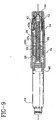
- the rear end portion 28b of half-nuts 28 abut splines 22b of plunger 22, as shown in Fig. 9.
- Locking ring 30 is slidably mounted within locking sleeve 31 such that the pair of pins 30d on locking ring 30 are mounted and travel within slot 31a at a distal end of locking sleeve 31.
- Locking ring 30 is axially movable within locking sleeve 31 but rotates with locking sleeve 31.
- Locking sleeve 31 also includes a pair of L-shaped grooves 31b that slidably receive each of the shafts 28d on half-nuts 28.
- Each pivot shaft 28d in conjunction with its respective L-shaped groove 31b on locking sleeve 31 and a long groove 16c within center body 16 provides a mechanism that prevents the removal of cartridge retainer 18 and cartridge 46 from housing 20, unless injector button 24 is in a down or loading position.
- injector button 24 is in the down or loading position and device 10 is in the proper position for receiving cartridge retainer 18 and, in particular, lugs 18a can enter slot 16a of center body 16.
- Fig. 7 injector button 24 is in the down or loading position and device 10 is in the proper position for receiving cartridge retainer 18 and, in particular, lugs 18a can enter slot 16a of center body 16.
- locking ring 30 is oriented so that tabs 30c do net block access to slot 16a and in this orientation pivot shafts 28d of half-nuts 28 are located in notches 31e at the end of each lower leg 31d of L-shaped groove 31b.
- cartridge retainer 18 is mated with center housing 16 such that lugs 18a enter slot 16a.
- cartridge retainer 18 is rotated in a clockwise direction such that lugs 18a drive tabs 30c in a clockwise direction which moves locking sleeve 31 and causes pivot shaft 28d to slide out of each notch 31e and into each leg 31d of each L-shaped groove 31b.
- spring 32 drives half-nuts 28 in the proximal direction to extend injector button 24 from the proximal end of assembly 10, if dose settings rings 36 and 38 are set to zero.
- upper body 14 includes an opening 14a in which a transparent window 34 is mounted.
- a units counter ring 36 and a tens counter ring 38 are positioned in adjoining relation beneath window 34, with both counter rings 36 and 38 including outer surfaces having numerals thereon visible through window 34.
- An O-ring 40 made from an elastomeric material is mounted in units counter ring 36 to hold a transmission key 44 in position.
- Transmission key 44 is provided for engaging and disengaging the units and tens counter rings 36, 38, and is located within a channel formed in units counter ring 36, as shown in Fig. 12.
- a zero detection clip 42 is positioned between the inner surfaces of counter rings 36 and 38 and the outer surface of plunger 22.
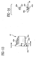
- Zero detection clip 42 as shown in Figs. 5b, 13 and 14, includes a generally cylindrical body 42a having a radially enlarged front end 42b.
- a lower spring member 42c extends axially within a slot formed within clip body 42a and includes a ridge 42d that is engageable with groove 38a formed within the inner surface of tens counter ring 38, as best shown in Fig. 14.
- Zero detection clip 42 also includes an axially extending upper-spring member 42e, the position of which is controlled by the rotational positions of the units and tens counter rings 36, 38.
- Upper spring member 42e includes a distal surface 42f that is engageable with splines 22b of plunger 22 when pushed into its active position by units counter ring 36 or by tens counter ring 38.
- the inner surface of units counter ring 36 functions as a cam and controls the radial position of upper spring member 42e of the zero detection clip 42.
- Clutch detent spring 15 includes a ring 15a having four internal tabs 15b that mount ring 15a onto units counter ring 36 and four legs 15c that are driven by rotation of adjusting knob 12.
- the present invention provides a clutch detent spring 15 that is made of a flexible metal that can be manufactured to provide a predetermined slip torque action between adjusting knob 12 and units counter ring 36.
- Fig. 6 is an enlarged perspective view of clutch detent spring 15 and shows its connection with adjusting knob 12, clutch nut 13 and units counter ring 36.
- Clutch detent spring 15 includes ring 15a having four outer legs 15c extending in the distal direction with each leg 15c having a protrusion 15d thereon extending away from rotational axis 15r of clutch detent spring 15.
- Internal tabs 15b correspond to notches 36a on units counter ring 36 that receive a respective internal tab 15b and hold clutch detent spring 15 onto units counter ring 36 together with the clutch nut 13 that is threaded onto units counter ring 36.
- cartridge retainer 18 is adapted for receiving a cartridge 46 of the type including an internal piston 46b and a pierceable seal 46a at one end thereof.
- a threaded end cap 19 is inserted through cartridge retainer 18 to extend from a distal end 18d of cartridge retainer 18 and is provided with threads 19a for securing a double ended needle assembly 50.
- the proximal end of cartridge retainer 18 includes the pair of bayonet lugs 18a on angular projections 18c that engage with the pair of slots 16a at the distal end of center body 16.
- Needle assembly 50 includes a cannula 50a having a sharp distal end 50b for piercing the skin of a patient or user and a sharp proximal end 50c for piercing pierceable seal 46a of cartridge 46 with a lumen (not shown) therethrough.
- Needle assembly 50 includes a cup-shaped hub 50d holding cannula 50a so that sharp proximal end 50c projects outwardly from the interior of cup-shaped hub 50d.
- Cup-shaped hub 50d includes an internal thread that is compatible with thread 19a on end cap 19, so that needle assembly 50 may be removably attached to end cap 19 with its sharp proximal end 50c piercing pierceable seal 46a to establish fluid communication with the interior of cartridge 46.
- cartridge 46 is loaded within the device, and a double ended needle assembly 50 is affixed to the end of cartridge retainer 18. Fluid communication is accordingly established between the injection portion of double ended needle assembly 50 and the interior of cartridge 46.
- push button 24 is urged forwardly, causing lead screw 26 to exert force upon piston 46b movably positioned within cartridge 46.
- Piston 46b displaces fluid within cartridge 46, causing its injection into body tissue through double ended needle assembly 50.
- the specific functions which are performed using the injection device are described separately herein. Assuming the device is loaded and push button 24 is in the down position, three steps are followed in the injection procedure: set to zero, set the dose, and make the injection.
- adjusting knob 12 is rotated back to the zero setting on both counter rings 36 and 38.
- adjusting knob 12 turns clutch detent spring 15 which then turns units counter ring 36. Because the splines on units counter ring 36 and plunger 22 are disengaged plunger 22 and the lead screw 26 do not turn.
- rings 36 and 38 reach zero, their slots align and release upper spring member 42e of zero detection clip 42.
- This releases plunger 22 and push button 24 which move under pressure from spring 32 via the two half nuts 28 until the proximal ends of large splines 22b of plunger 22 are stopped by an inner surface of units counter ring 36.
- This movement also carries lead screw 26. Small splines 22d on the plunger 22 engage with the splined units counter ring 36 and are ready for setting a dose.
- Adjusting knob 12 is then rotated away from the zero (0) setting. Adjusting knob 12 turns clutch detent spring 15, which turns units counter ring 36, which turns plunger 22. Plunger 22 is engaged with longitudinal grooves 26d in lead screw 26 which turns and screws forward in the nut formed by the two half nuts 28. The lead screw's travel is proportional to the number of units displayed by the counter rings 36, 38.
- push button 24 When the desired dose has been set, push button 24 is pushed fully in which pushes plunger 22, two half nuts 28, and lead screw 26 forwards. Plunger and lead screw 26, as coupled by half nuts 28, accordingly perform the function of a piston rod.
- the total travel is determined by push button 24 that slides into and is stopped by adjusting knob 12. The first part of the travel brings the end of lead screw 26 into contact with piston 46b of cartridge 46; the second part of the travel moves piston 46b of cartridge 46 forward and delivers the measured amount of medication.
- lead screw 26 While setting the dose, lead screw 26 is moved forward in proportion to the dosage set; this distance determines the proportion of the pre-injection and injection travel. Plunger 22 and push button 24 are locked in position by upper spring member 42e of the zero detection clip 42 following an injection.
- Zero detection clip 42 includes a clicker 42g that generates a click for each unit as it passes over larger splines 22b on plunger 22.
- Units counter ring 36 drives the tens counter ring 38 through 36 degrees of rotation every time units counter ring 36 passes zero via transmission key 44.
- Lower spring member 42e of zero detection clip 42 has a ridge 42d which engages with the grooves 38a inside the tens counter ring 38 and creates a click every time the tens counter ring 38 turns.
- TMDD maximum dialable dose
- lead screw 26 The travel of lead screw 26 is limited to the safe travel of piston 46b in the cartridge 46. If lead screw 26 reaches the end of its travel, projections 22c inside plunger 22 reach the end of grooves 26d in lead screw 26 and prevent it from further movement. Lead screw 26 prevents plunger 22 and counter rings 36 and 38 from turning. Adjusting knob 12 will then cause clutch detent spring 15 to slip without further effect. The counter rings will indicate the travel of the lead screw to this point, and therefore, the quantity of insulin remaining in the cartridge.
- the counter rings When adjusting knob 12 is rotated away from the zero (0) setting, and there are more than TMDD units remaining in cartridge 46, the counter rings will stop at TMDD units as described above. If there are less than TMDD units remaining, the counter rings will stop as described above and display the remaining capacity of cartridge 46. In either case, the user can then turn adjusting knob 12 back until the counter rings display the dose to be administered.
- push button 24 can be left in the loading position.
- cartridge retainer 18 can be removed from center body 16 of housing 20 and cartridge 46 can be removed.
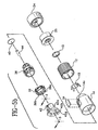
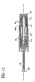
- cartridge retainer 18 is removed from housing 20, the elliptical shape defined by the inner wall of locking ring 30 allows two half nuts 28 to open under pressure from spring 32 and to free lead screw 26, as shown in Fig. 11.
- a new cartridge 46 can then be inserted into cartridge retainer 18 which is then locked back onto center body 16 using the bayonet or lugs 18a on cartridge retainer 18.
- Cartridge retainer 18 has two angular projections 18c that engage with angular projections 30c extending from locking ring 30.
- the projections 18c and 30c cause locking ring 30 to turn the same amount.
- cartridge retainer 18 is prevented from turning further.
- the elliptical inner wall of locking ring 30 moves two half nuts 28 into engagement with lead screw 26. The position of lead screw 26 is then determined by the position of the piston 46b in cartridge 46.
- Upper body 14 houses the four parts which comprise the counter mechanism.
- Window 34 in upper body 14 shows the numbers printed on the outside of the two counter rings 36 and 38, and indicates the number of units to be injected from 0 to TMDD.
- Units counter ring 36 is turned by adjusting knob 12 through clutch detent spring 15.
- transmission key 44 meets the cam molded inside upper body 14.
- the transmission key 44 is then forced to slide up the face of the cam, and reaches the top in position "9".
- the elastic ring 40 is flexed by this movement and maintains the transmission key 44 in contact with the cam. This movement also brings the opposite end of transmission key 44 into engagement with one of the slots 38b inside the tens counter ring 38, shown in Fig. 5b.
- transmission key 44 transmits the movement to tens counter ring 38, and the two rings turn together.
- the window 34 now displays “10” and transmission key 44 has rotated 36 degrees to the end of the raised face of the cam inside the upper body 14.
- the tens counter ring 38 has stops in the "0" and TMDD positions to prevent the counter mechanism from going beyond a maximum reading of TMDD or a minimum reading of 0 units. In both of these positions the transmission key 44 is in its active, engaged position. It should be noted that if the stops for the tens counter ring 38 were moved, the reading could continue up to 99 units.
- the slot in units counter ring 36 has an angled face which works as a cam, forcing the upper spring member 42e down into its active position as soon as the units counter ring 36 leaves the "0" position.
- the units counter ring 36 holds the zero detection clip 42 in its active position up to position "9".
- position "10” the tens counter ring 38 has moved, and now holds the zero detection clip 42 in its active position. From position "10" to position TMDD zero detection clip 42 is held in its active position by tens counter ring 38.
- plunger 22 slides through the zero detection clip 42 until the end of its travel. At this point the end of upper spring member 42e drops behind the end of spline 22b and prevents plunger 22 from moving out under pressure from spring 32.
- the components can be designed so that this movement will make a clicking sound, confirming that a complete injection has been made.
- Cartridge 46 is easily loaded and substantially fully visible to the user. Two way dosage adjustment is possible, which allows corrections to be made quickly and easily.
- the dosage to be administered is clearly displayed and will remain displayed subsequent to the injection procedure.
- the device produces a click and locks in the closed position only when the plunger is fully inserted.
Description
- The subject invention relates to an improved medication delivery pen.
- Hypodermic syringes are used to deliver selected doses of medication to patients. The prior art hypodermic syringe includes a syringe barrel having opposed proximal and distal ends. A cylindrical chamber wall extends between the ends and defines a fluid receiving chamber. The proximal end of the prior art syringe barrel is substantially open and receives a plunger in sliding fluid tight engagement. The distal end of the prior art syringe barrel includes a passage communicating with the chamber. A needle cannula may be mounted to the distal end of the prior art syringe barrel, such that the lumen of the needle cannula communicates with the passage and the chamber of the syringe barrel. Movement of the plunger in a proximal direction draws fluid through the lumen of the needle cannula and into the chamber. Movement of the plunger in a proximal-to-distal direction urges fluid from the chamber and through the lumen of the needle cannula.
- Medication to be injected with the prior art hypodermic syringe often is stored in a vial having a pierceable elastomeric seal. Medication in the prior art vial is accessed by piercing the elastomeric seal with the needle cannula. A selected dose of the medication may be drawn into the chamber of the syringe barrel by moving the plunger a selected distance in a proximal direction. The needle cannula may be withdrawn from the vial, and the medication may be injected into a patient by moving the plunger in a distal direction.
- Some medication, such as insulin is self-administered. The typical diabetes patient will require injections of insulin several times during the course of a week or day. The required dose of insulin will vary from patient to patient, and for each patient may vary during the course of the day and from day to day. Each diabetes patient will establish a regimen that is appropriate for his or her own medical condition and for his or her lifestyle. The regimen typically includes some combination of a slow or medium acting insulin and a faster acting insulin. Each of these regimens may require the diabetes patient to periodically self-administer insulin in public locations, such as places of employment or restaurants. The required manipulation of the standard prior art hypodermic syringe and vial can be inconvenient and embarrassing in these public environments.
- Medication delivery pens have been developed to facilitate the self-administration of medication. One prior art medication delivery pen described in U.S. Patent No. 5,279,585 includes a vial holder into which a vial of insulin or other medication may be received. The vial holder is an elongate generally tubular structure with proximal and distal ends. The distal end of the prior art vial holder includes mounting means for engaging a double-ended needle cannula. The proximal end also includes mounting means for engaging a driver and dose setting apparatus as explained further below. A disposable vial for use with the prior art vial holder includes a distal end having a pierceable elastomeric seal that can be pierced by one end of a double-ended needle cannula. The proximal end of this prior art vial includes a plunger slidably disposed in fluid tight engagement with the cylindrical wall of the vial. This prior art medication delivery pen is used by inserting the vial of medication into the vial holder. A prior art pen body then is connected to the proximal end of the vial holder. The pen body includes a dose setting apparatus for designating a dose of medication to be delivered by the pen and a driving apparatus for urging the plunger of the vial distally for a distance corresponding to the selected dose.
- The user of the pen mounts a prior art double-ended needle cannula to the distal end of the vial holder such that the proximal point cannula of the needle cannula pierces the elastomeric seal on the vial. The user then selects a dose and operates the pen to urge the plunger distally to deliver the selected dose. The user then removes and discards the needle cannula, and keeps the prior art medication delivery pen in a convenient location for the next required medication administration. The medication in the vial will become exhausted after several such administrations of medication. The user then separates the vial holder from the pen body. The empty vial may then be removed and discarded. A new vial can be inserted into the vial holder, and the vial holder and pen body can be reassembled and used again as explained above.
- The above described reusable medication delivery pen is effective and much more convenient for self-administration of medication than the typical hypodermic syringe and separate medication vial. However, it has been found that there is the needle for additional features and improvements for such a medication delivery pen. For example, there is the need to prevent removal of the vial unless the injector button of the medication delivery pen is in a selected position, to provide improved control over the torques available or necessary to rotate a unit indicator using a dose setting apparatus, and to generally strengthen or otherwise improve the dose setting apparatus in the mediation delivery pen.
- According to WO 9626754, a mechanism for accurate dispensing of pre-set quantities of medicament from a syringe has a plunger rotatable within a housing, which plunger has a cam surface engaged by a fixed follower such that rotation of the plunger moves the plunger away from the syringe. Internally within the plunger there is a number of parallel racks each of which in turn comes into engagement with a first toothed wheel on rotation of the plunger. The first toothed wheel is connected to a second toothed wheel which runs on a fixed rack extending within the plunger parallel to axis thereof. The first toothed wheel is coupled to a thrust rod for the piston of the syringe. After pre-setting a required dose by rotation of the plunger, the plunger is then pushed towards the syringe, so rotating the first and second toothed wheels. This drives the thrust rod into the syringe but by appropriate selection of the toothed wheel diameters and the tooth pitch thereof, an advantageous velocity ratio between the plunger and thrust rod movements may be obtained.
- According to the present, there is provided a medication delivery pen comprising:
- a housing comprising a distal end and a proximal end;
- a cartridge retainer for receiving a cartridge containing medication, said cartridge retainer being removably mountable on the distal end of said housing;
- means in said housing for setting a desired dose of medication to be dispensed from the cartridge having a rotatable dose setting knob and a dosing ring that displays the amount of the desired dose being set;
- means in said housing for dispensing the desired dose of medication from the cartridge; and
- means in said dose setting means for controlling torque applied by said rotatable dose setting knob to said dosing ring during rotation of said dosing knob, wherein said means for controlling the torque applied by said rotatable dose setting knob to said dosing ring during rotation of said dosing knob includes a clutch; characterised in that said clutch includes a clutch detent spring attached to said dosing ring and rotatably mounted to said dose setting knob to rotate within said dose setting knob when a predetermined torque is applied to said dose setting knob, said clutch detent spring including a plurality of outer legs and a plurality of internal tabs, wherein said internal tabs attach to said dosing ring and said outer legs are in sliding contact with said dose setting knob.
-
- An object of the present invention is to improve the clutch assembly in the medication delivery pen to provide more control over the torques necessary to rotate the unit indicator in the pen using the rotation of a dosing knob in the dose setting apparatus.
- These and other aspects, features and advantages of the present invention will become apparent from the following detailed description taken in conjunction with the accompanying drawings.
-
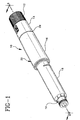
- Fig. 1 is a perspective view of a medication delivery pen of the subject invention;
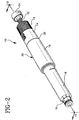
- Fig. 2 is a perspective view of the medication delivery pen shown in Fig. 1 with the plunger extended;
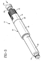
- Fig. 3 is a perspective view of the medication delivery pen shown in Fig. 1 with the plunger moving axially during an injection;
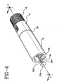
- Fig. 4 is a perspective view of the medication delivery pen shown in Fig. 1 with the cartridge retainer removed;
- Figs. 5a and 5b are exploded perspective views of the pen shown in Fig. 1 further including a needle assembly;
- Fig. 6 is an enlarged perspective of the clutch assembly;
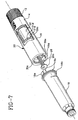
- Fig. 7 is an exploded perspective view of the medication delivery pen shown in Fig. 1 with the cartridge retainer removed;
- Fig. 8 is another perspective view of the medication delivery pen shown in Fig. 1 with the cartridge retainer attached and locked onto the upper body;
- Fig. 9 is a cross sectional view taken along lines 9-9 as shown in Fig. 1;
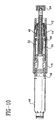
- Fig. 10 is a cross sectional view taken along lines 10-10 as shown in Fig. 2;
- Fig. 11 is a cross sectional view taken along lines 11-11 as shown in Fig. 4;
- Fig. 12 is an enlarged cross sectional view of the medication delivery pen shown in Figs. 2 and 10 to more clearly show the clutch assembly;
- Fig. 13 is an enlarged cross sectional view of the zero detection clip shown in Fig. 5b; and
- Fig. 14 is a cross sectional view taken along lines 14-14 as shown in Fig. 13.
-
- An
improved injection device 10 for injecting insulin or other medication is provided by the present invention. As shown in Figs. 1-3, the device includes an adjustingknob 12, anupper body 14, acenter body 16, and acartridge retainer 18 All of these elements have a generally cylindrical configuration and are arranged coaxially to define a generallycylindrical housing 20 which can easily be handled by a patient or medical attendant. - Referring to Figs. 4, 5a and 7-12, a
plunger 22 is at least partially positioned within the portion ofhousing 20 defined by adjustingknob 12,upper body 14 andcenter body 16.Plunger 22 includes a hollow, substantially cylindrical body 22a including a band of radially projectingsplines 22b extending outwardly therefrom. A pair of opposingprojections 22c extend radially inwardly from the front end of the cylindrical body 22a. As shown in Figs. 5a and 5b, the rear end ofplunger 22 is secured to ahub 25 having arotatable push button 24 snapped therein.Push button 24 fits partially within adjustingknob 12 whenplunger 22 is fully inserted withinhousing 20. - A
lead screw 26 is positioned within and coaxially withplunger 22 and includes an enlargedfront end 26a and a taperedrear end 26b, connected by an elongate threadedbody 26c. A pair oflongitudinal grooves 26d are formed within threadedbody 26c and receive the radially inwardly extendingprojections 22c ofplunger 22. Leadscrew 26 is accordingly rotatable withplunger 22 and capable of sliding axially with respect toplunger 22. - A pair of half-
nuts 28 are positioned withincenter body 16, with each half-nut 28 including asemi-cylindrical body portion 28a and a radiallyenlarged end portion 28b. The front end of each half-nut 28 includesthreads 28c that are used to threadably engage withlead screw 26 and the rear end of each half-nut 28 includes apivot shaft 28d that receives ametal pin 28e to provide an axis about which each half-nut 28 can pivot. Metal pins 28e inserted in eachpivot shaft 28d also provide more definite control over the dose setting operation, described below, and prevent skewing of half nuts 28 on threadedlead screw 26.Body portions 28a of half-nuts 28 are positioned at least partially within a lockingring 30 having a hollow, generallycylindrical body portion 30a defining a generallyelliptical passage 30e for receiving half-nuts 28. Afront end 30b of lockingring 30 is radially enlarged and includes a pair ofangular projections 30c that extend axially from the front end of lockingring 30 and the side of lockingring 30 includes a pair ofpins 30d. Theproximal end 18b ofcartridge retainer 18 includes a pair ofangular projections 18c that are spaced to receiveangular projections 30c whencartridge retainer 18 is mounted onhousing 20, which is described further below. - A
helical coil spring 32 is positioned over lockingring 30 and half-nuts 28 and through lockingsleeve 31, with one end ofcoil spring 32 bearing against the radially enlargedportions 28b of half-nuts 28 while the opposite end ofcoil spring 32 bears against the radially enlargedfront end 30b of lockingring 30.Front end 30b of lockingring 30 mounts withincenter body 16 which also receives finishingring 29. Therear end portion 28b of half-nuts 28abut splines 22b ofplunger 22, as shown in Fig. 9. - Locking
ring 30 is slidably mounted within lockingsleeve 31 such that the pair ofpins 30d on lockingring 30 are mounted and travel withinslot 31a at a distal end of lockingsleeve 31. With thisstructure locking ring 30 is axially movable within lockingsleeve 31 but rotates with lockingsleeve 31. Lockingsleeve 31 also includes a pair of L-shapedgrooves 31b that slidably receive each of theshafts 28d on half-nuts 28. Eachpivot shaft 28d in conjunction with its respective L-shapedgroove 31b on lockingsleeve 31 and along groove 16c withincenter body 16 provides a mechanism that prevents the removal ofcartridge retainer 18 andcartridge 46 fromhousing 20, unlessinjector button 24 is in a down or loading position. This feature is more clearly shown in Figs. 7 and 8. In Fig. 7injector button 24 is in the down or loading position anddevice 10 is in the proper position for receivingcartridge retainer 18 and, in particular, lugs 18a can enterslot 16a ofcenter body 16. As shown in Fig. 7, lockingring 30 is oriented so thattabs 30c do net block access toslot 16a and in thisorientation pivot shafts 28d of half-nuts 28 are located innotches 31e at the end of each lower leg 31d of L-shapedgroove 31b. After acartridge 46 has been loaded intocartridge retainer 18,cartridge retainer 18 is mated withcenter housing 16 such that lugs18a enter slot 16a. Then, as shown in Fig. 8,cartridge retainer 18 is rotated in a clockwise direction such that lugs18a drive tabs 30c in a clockwise direction which moves lockingsleeve 31 and causespivot shaft 28d to slide out of eachnotch 31e and into each leg 31d of each L-shapedgroove 31b. At this point,spring 32 drives half-nuts 28 in the proximal direction to extendinjector button 24 from the proximal end ofassembly 10, if dose settings rings 36 and 38 are set to zero. - As shown in Fig. 5b,
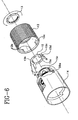
upper body 14 includes anopening 14a in which atransparent window 34 is mounted. A units counterring 36 and atens counter ring 38 are positioned in adjoining relation beneathwindow 34, with both counter rings 36 and 38 including outer surfaces having numerals thereon visible throughwindow 34. - An O-
ring 40 made from an elastomeric material is mounted in units counterring 36 to hold atransmission key 44 in position.Transmission key 44 is provided for engaging and disengaging the units and tens counter rings 36, 38, and is located within a channel formed in units counterring 36, as shown in Fig. 12. A zerodetection clip 42, more clearly shown in Figs. 13 and 14, is positioned between the inner surfaces of counter rings 36 and 38 and the outer surface ofplunger 22. Zerodetection clip 42, as shown in Figs. 5b, 13 and 14, includes a generallycylindrical body 42a having a radially enlargedfront end 42b. Alower spring member 42c extends axially within a slot formed withinclip body 42a and includes aridge 42d that is engageable withgroove 38a formed within the inner surface of tens counterring 38, as best shown in Fig. 14. Zerodetection clip 42 also includes an axially extending upper-spring member 42e, the position of which is controlled by the rotational positions of the units and tens counter rings 36, 38.Upper spring member 42e includes adistal surface 42f that is engageable withsplines 22b ofplunger 22 when pushed into its active position by units counterring 36 or by tens counterring 38. The inner surface of units counterring 36 functions as a cam and controls the radial position ofupper spring member 42e of the zerodetection clip 42. - The inner surface of units counter
ring 36 is splined, with the spline surface being engageable withsmall splines 22d ofplunger 22. Engagement betweenring 36 andplunger 22 occurs whenspring 32 is in the extended position shown in Fig. 10. Units counterring 36 is then driven by adjustingknob 12 through a specially designedclutch detent spring 15, more clearly shown in Fig. 6.Clutch detent spring 15 includes aring 15a having fourinternal tabs 15b that mountring 15a onto units counterring 36 and fourlegs 15c that are driven by rotation of adjustingknob 12. The present invention provides aclutch detent spring 15 that is made of a flexible metal that can be manufactured to provide a predetermined slip torque action between adjustingknob 12 and units counterring 36. - Fig. 6 is an enlarged perspective view of
clutch detent spring 15 and shows its connection with adjustingknob 12,clutch nut 13 and units counterring 36.Clutch detent spring 15 includesring 15a having fourouter legs 15c extending in the distal direction with eachleg 15c having aprotrusion 15d thereon extending away fromrotational axis 15r ofclutch detent spring 15.Internal tabs 15b correspond tonotches 36a on units counterring 36 that receive a respectiveinternal tab 15b and holdclutch detent spring 15 onto units counterring 36 together with theclutch nut 13 that is threaded onto units counterring 36. When units counterring 36 withclutch detent spring 15 mounted thereon is assembled into adjustingknob 12,protrusions 15d onclutch detent spring 15 mate withinner surface 12a of adjustingknob 12 and travel indetents 12b oninner surface 12a until a predetermined torque is encountered by units counterring 36 which then causesclutch detent spring 15 to rotate with respect to adjustingknob 12. The important feature of the present invention is that when theclutch detent spring 15 is manufactured with angle Θ of eachouter leg 15c with respect torotational axis 15r, theclutch detent spring 15 is preset to provide release from adjustingknob 12 at a predetermined torque. - As shown in Fig. 5a,
cartridge retainer 18 is adapted for receiving acartridge 46 of the type including aninternal piston 46b and apierceable seal 46a at one end thereof. A threadedend cap 19 is inserted throughcartridge retainer 18 to extend from adistal end 18d ofcartridge retainer 18 and is provided withthreads 19a for securing a double endedneedle assembly 50. The proximal end ofcartridge retainer 18 includes the pair of bayonet lugs 18a onangular projections 18c that engage with the pair ofslots 16a at the distal end ofcenter body 16. -
Needle assembly 50 includes acannula 50a having a sharpdistal end 50b for piercing the skin of a patient or user and a sharpproximal end 50c for piercingpierceable seal 46a ofcartridge 46 with a lumen (not shown) therethrough.Needle assembly 50 includes a cup-shapedhub 50d holding cannula 50a so that sharpproximal end 50c projects outwardly from the interior of cup-shapedhub 50d. Cup-shapedhub 50d includes an internal thread that is compatible withthread 19a onend cap 19, so thatneedle assembly 50 may be removably attached to endcap 19 with its sharpproximal end 50c piercingpierceable seal 46a to establish fluid communication with the interior ofcartridge 46. - The operation of the
injection device 10 shall now be described with reference to the accompanying figures. Generally speaking,cartridge 46 is loaded within the device, and a double endedneedle assembly 50 is affixed to the end ofcartridge retainer 18. Fluid communication is accordingly established between the injection portion of double endedneedle assembly 50 and the interior ofcartridge 46. Once the appropriate dosage is set,push button 24 is urged forwardly, causinglead screw 26 to exert force uponpiston 46b movably positioned withincartridge 46.Piston 46b displaces fluid withincartridge 46, causing its injection into body tissue through double endedneedle assembly 50. The specific functions which are performed using the injection device are described separately herein. Assuming the device is loaded andpush button 24 is in the down position, three steps are followed in the injection procedure: set to zero, set the dose, and make the injection. - First, adjusting
knob 12 is rotated back to the zero setting on both counter rings 36 and 38. As will be described in more detail hereinbelow, adjustingknob 12 turnsclutch detent spring 15 which then turns units counterring 36. Because the splines on units counterring 36 andplunger 22 are disengagedplunger 22 and thelead screw 26 do not turn. When rings 36 and 38 reach zero, their slots align and releaseupper spring member 42e of zerodetection clip 42. This in turn releasesplunger 22 andpush button 24 which move under pressure fromspring 32 via the twohalf nuts 28 until the proximal ends oflarge splines 22b ofplunger 22 are stopped by an inner surface of units counterring 36. This movement also carrieslead screw 26.Small splines 22d on theplunger 22 engage with the splined units counterring 36 and are ready for setting a dose. - Adjusting
knob 12 is then rotated away from the zero (0) setting. Adjustingknob 12 turnsclutch detent spring 15, which turns units counterring 36, which turnsplunger 22.Plunger 22 is engaged withlongitudinal grooves 26d inlead screw 26 which turns and screws forward in the nut formed by the two half nuts 28. The lead screw's travel is proportional to the number of units displayed by the counter rings 36, 38. - When the desired dose has been set,
push button 24 is pushed fully in which pushesplunger 22, twohalf nuts 28, and leadscrew 26 forwards. Plunger andlead screw 26, as coupled byhalf nuts 28, accordingly perform the function of a piston rod. The total travel is determined bypush button 24 that slides into and is stopped by adjustingknob 12. The first part of the travel brings the end oflead screw 26 into contact withpiston 46b ofcartridge 46; the second part of the travel movespiston 46b ofcartridge 46 forward and delivers the measured amount of medication. While setting the dose,lead screw 26 is moved forward in proportion to the dosage set; this distance determines the proportion of the pre-injection and injection travel.Plunger 22 andpush button 24 are locked in position byupper spring member 42e of the zerodetection clip 42 following an injection. - When a dose is set, units counter
ring 36 pushesupper spring member 42e of zerodetection clip 42 into its active position. Zerodetection clip 42 includes aclicker 42g that generates a click for each unit as it passes overlarger splines 22b onplunger 22. Units counterring 36 drives the tens counterring 38 through 36 degrees of rotation every time units counterring 36 passes zero viatransmission key 44.Lower spring member 42e of zerodetection clip 42 has aridge 42d which engages with thegrooves 38a inside the tens counterring 38 and creates a click every time the tens counterring 38 turns. - If the dose is set at the maximum dialable dose (hereinafter "TMDD"), tens counter
ring 38 reaches a stop, andtransmission key 44 engages in the last location in the tens counterring 38. If adjustingknob 12 is turned further, rings 36 and 38 are unable to turn and adjustingknob 12 slips without further effect.Clutch detent spring 15 is designed to limit the torque which will be transmitted to the counter rings and prevents unintentional damage. - The travel of
lead screw 26 is limited to the safe travel ofpiston 46b in thecartridge 46. Iflead screw 26 reaches the end of its travel,projections 22c insideplunger 22 reach the end ofgrooves 26d inlead screw 26 and prevent it from further movement. Leadscrew 26 preventsplunger 22 and counter rings 36 and 38 from turning. Adjustingknob 12 will then causeclutch detent spring 15 to slip without further effect. The counter rings will indicate the travel of the lead screw to this point, and therefore, the quantity of insulin remaining in the cartridge. - When adjusting
knob 12 is rotated away from the zero (0) setting, and there are more than TMDD units remaining incartridge 46, the counter rings will stop at TMDD units as described above. If there are less than TMDD units remaining, the counter rings will stop as described above and display the remaining capacity ofcartridge 46. In either case, the user can then turn adjustingknob 12 back until the counter rings display the dose to be administered. - After a complete injection has been made,
push button 24 can be left in the loading position. As described above, whendevice 10 is in the loadingposition cartridge retainer 18 can be removed fromcenter body 16 ofhousing 20 andcartridge 46 can be removed. Whencartridge retainer 18 is removed fromhousing 20, the elliptical shape defined by the inner wall of lockingring 30 allows twohalf nuts 28 to open under pressure fromspring 32 and tofree lead screw 26, as shown in Fig. 11. - A
new cartridge 46 can then be inserted intocartridge retainer 18 which is then locked back ontocenter body 16 using the bayonet or lugs 18a oncartridge retainer 18. Ascartridge retainer 18 moves towardscenter body 16,piston 46b ofcartridge 46 will pushlead screw 26 into the device.Cartridge retainer 18 has twoangular projections 18c that engage withangular projections 30c extending from lockingring 30. Whencartridge retainer 18 is then rotated theprojections cause locking ring 30 to turn the same amount. In addition, aftercartridge retainer 18 has rotated and eachlug 18a oncartridge retainer 18 has entered itsrespective recess 16b inslot 16a insidecenter body 16,cartridge retainer 18 is prevented from turning further. The elliptical inner wall of lockingring 30 moves twohalf nuts 28 into engagement withlead screw 26. The position oflead screw 26 is then determined by the position of thepiston 46b incartridge 46. -
Upper body 14 houses the four parts which comprise the counter mechanism.Window 34 inupper body 14 shows the numbers printed on the outside of the two counter rings 36 and 38, and indicates the number of units to be injected from 0 to TMDD. Units counterring 36 is turned by adjustingknob 12 throughclutch detent spring 15. When units counterring 36 has turned to numbered position "8",transmission key 44 meets the cam molded insideupper body 14. Thetransmission key 44 is then forced to slide up the face of the cam, and reaches the top in position "9". Theelastic ring 40 is flexed by this movement and maintains thetransmission key 44 in contact with the cam. This movement also brings the opposite end oftransmission key 44 into engagement with one of theslots 38b inside the tens counterring 38, shown in Fig. 5b. When units counterring 36 is turned further,transmission key 44 transmits the movement totens counter ring 38, and the two rings turn together. At position "10" thewindow 34 now displays "10" andtransmission key 44 has rotated 36 degrees to the end of the raised face of the cam inside theupper body 14. - If units counter
ring 36 is turned further,transmission key 44 is free to slide down the face of the cam insideupper body 14 under pressure fromelastic ring 40. This movement disengages the two counter rings, and the counter will now read "11". This movement is repeated each time the units counterring 36 moves from position "8", through positions "9" and "0" to position "1". The reverse procedure is identical. - The tens counter
ring 38 has stops in the "0" and TMDD positions to prevent the counter mechanism from going beyond a maximum reading of TMDD or a minimum reading of 0 units. In both of these positions thetransmission key 44 is in its active, engaged position. It should be noted that if the stops for the tens counterring 38 were moved, the reading could continue up to 99 units. - The slot in units counter
ring 36 has an angled face which works as a cam, forcing theupper spring member 42e down into its active position as soon as the units counterring 36 leaves the "0" position. The units counterring 36 holds the zerodetection clip 42 in its active position up to position "9". In position "10" the tens counterring 38 has moved, and now holds the zerodetection clip 42 in its active position. From position "10" to position TMDD zerodetection clip 42 is held in its active position by tens counterring 38. When an injection is made,plunger 22 slides through the zerodetection clip 42 until the end of its travel. At this point the end ofupper spring member 42e drops behind the end ofspline 22b and preventsplunger 22 from moving out under pressure fromspring 32. The components can be designed so that this movement will make a clicking sound, confirming that a complete injection has been made. - When the counter is set to "0" as shown in Fig. 10, the slots inside the two counter rings 36 and 38 align with
upper spring member 42e of zerodetection clip 42 and allow it to spring up into its rest position. This movement freesplunger 22 and allows a new dose to be set. -
Cartridge 46 is easily loaded and substantially fully visible to the user. Two way dosage adjustment is possible, which allows corrections to be made quickly and easily. The dosage to be administered is clearly displayed and will remain displayed subsequent to the injection procedure. In order to insure that a complete injection has been made, the device produces a click and locks in the closed position only when the plunger is fully inserted. - While the invention has been described with respect to a preferred embodiment illustrated in Figs. 1-14, it should be understood that variations from this preferred embodiment may be provided, and are considered to be within the scope of the subject invention.
Claims (6)
- A medication delivery pen comprising:characterised in that said clutch includes a clutch detent spring (15) attached to said dosing ring (36) and rotatably mounted to said dose setting knob (12) to rotate within said dose setting knob (12) when a predetermined torque is applied to said dose setting knob (12), said clutch detent spring (15) including a plurality of outer legs (15c) and a plurality of internal tabs (15b), wherein said internal tabs (15b) attach to said dosing ring (36) and said outer legs (15c) are in sliding contact with said dose setting knob (12).a housing (20) comprising a distal end and a proximal end;a cartridge retainer (18) for receiving a cartridge containing medication (46), said cartridge retainer (18) being removably mountable on the distal end of said housing (20);means in said housing (20) for setting a desired dose of medication to be dispensed from the cartridge (46) having a rotatable dose setting knob (12) and a dosing ring (36) that displays the amount of the desired dose being set;means in said housing (20) for dispensing the desired dose of medication from the cartridge (46); andmeans in said dose setting means for controlling torque applied by said rotatable dose setting knob (12) to said dosing ring during rotation of said dosing knob (12), wherein said means for controlling the torque applied by said rotatable dose setting knob (12) to said dosing ring (36) during rotation of said dosing knob (12) includes a clutch;
- A medication delivery pen according to Claim 1, wherein said dose setting knob (12) includes a plurality of detents (12b) on an inner surface (12a) and each of said plurality of outer legs (15c) on said clutch detent spring (15) includes a protrusion (15d) that rides in a respective one of said plurality of detents (12b) until said predetermined torque is applied to said dose setting knob (20), which then causes each of said plurality of protrusions (15d) to slip out of each of said plurality of detents (12b).
- A medication delivery pen according to Claim 2, wherein each of said outer legs (15c) are positioned at an angle Θ such that said predetermined torque can be applied to said dosing ring (36) by said dose setting knob (12).
- A medication delivery pen according to Claim 1, further comprising attachment means between said cartridge retainer and said housing for attaching and unattaching said cartridge retainer to said housing.
- A medication delivery pen according to Claim 4, wherein said attachment means is a bayonet (18a).
- A medication delivery pen according to Claim 5, wherein said bayonet (18a) includes a pair of projections (18c) on the proximal end of said cartridge retainer (18) and a pair of slots (16a) in the distal end of said housing (20).
Applications Claiming Priority (3)
| Application Number | Priority Date | Filing Date | Title |
|---|---|---|---|
| US909222 | 1997-08-11 | ||
| US08/909,376 US5957896A (en) | 1997-08-11 | 1997-08-11 | Medication delivery pen |
| US08/909,222 US5921966A (en) | 1997-08-11 | 1997-08-11 | Medication delivery pen having an improved clutch assembly |
Publications (3)
| Publication Number | Publication Date |
|---|---|
| EP0897729A2 EP0897729A2 (en) | 1999-02-24 |
| EP0897729A3 EP0897729A3 (en) | 1999-12-22 |
| EP0897729B1 true EP0897729B1 (en) | 2003-01-22 |
Family
ID=37496642
Family Applications (2)
| Application Number | Title | Priority Date | Filing Date |
|---|---|---|---|
| EP98306376A Expired - Lifetime EP0897729B1 (en) | 1997-08-11 | 1998-08-10 | Medication delivery pen having a controlling means of the torque applied to the dosing elements |
| EP98306378A Expired - Lifetime EP0897728B1 (en) | 1997-08-11 | 1998-08-10 | Medication delivery pen |
Family Applications After (1)
| Application Number | Title | Priority Date | Filing Date |
|---|---|---|---|
| EP98306378A Expired - Lifetime EP0897728B1 (en) | 1997-08-11 | 1998-08-10 | Medication delivery pen |
Country Status (5)
| Country | Link |
|---|---|
| US (2) | US5957896A (en) |
| EP (2) | EP0897729B1 (en) |
| JP (2) | JP4395206B2 (en) |
| CA (2) | CA2244170C (en) |
| DE (2) | DE69810860T2 (en) |
Cited By (3)
| Publication number | Priority date | Publication date | Assignee | Title |
|---|---|---|---|---|
| WO2003097131A1 (en) * | 2002-05-15 | 2003-11-27 | Aventis Pharma Deutschland Gmbh | Device for guiding a drive |
| WO2003097132A1 (en) * | 2002-05-15 | 2003-11-27 | Aventis Pharma Deutschland Gmbh | Device for guiding a drive |
| CN101094701B (en) * | 2004-12-31 | 2011-02-23 | 特克法马许可公司 | Device for the dosed administration of a fluid product, provided with decoupling means for the replacement of a container |
Families Citing this family (423)
| Publication number | Priority date | Publication date | Assignee | Title |
|---|---|---|---|---|
| JP4423457B2 (en) | 1998-01-16 | 2010-03-03 | トルーデル メディカル インターナショナル | Dispenser and administration device display device |
| PL191327B1 (en) | 1998-01-30 | 2006-04-28 | Novo Nordisk As | Syringe |
| GB9807558D0 (en) * | 1998-04-09 | 1998-06-10 | Bason Neil P | An indicator device |
| US6729330B2 (en) | 1998-05-05 | 2004-05-04 | Trudell Medical International | Indicating device for aerosol container |
| US6082358A (en) | 1998-05-05 | 2000-07-04 | 1263152 Ontario Inc. | Indicating device for aerosol container |
| WO2001010484A1 (en) * | 1999-08-05 | 2001-02-15 | Becton, Dickinson And Company | Medication delivery pen |
| US6277099B1 (en) * | 1999-08-06 | 2001-08-21 | Becton, Dickinson And Company | Medication delivery pen |
| TW453884B (en) | 1999-09-16 | 2001-09-11 | Novo Nordisk As | Dose setting limiter |
| US6673035B1 (en) * | 1999-10-22 | 2004-01-06 | Antares Pharma, Inc. | Medical injector and medicament loading system for use therewith |
| US6585698B1 (en) * | 1999-11-01 | 2003-07-01 | Becton, Dickinson & Company | Electronic medical delivery pen having a multifunction actuator |
| DK1104683T3 (en) | 1999-12-03 | 2005-08-22 | Mattern Udo | Combination of an apparatus for injecting antiparasitics in livestock and an antiparasitic biologically active substance |
| GB2375965B (en) * | 2000-01-28 | 2004-09-01 | Novo Nordisk As | A dose setting limiter |
| US6706031B2 (en) * | 2000-02-15 | 2004-03-16 | Comar, Inc. | Needleless access apparatus and system |
| DK1263387T3 (en) * | 2000-02-16 | 2005-01-24 | Haselmeier S A R L | Method of Reconstituting an Injection Fluid and Injection Equipment for Exercising Such Procedure |
| JP3788164B2 (en) | 2000-02-21 | 2006-06-21 | 東海ゴム工業株式会社 | Fluid filled mount |
| DE10015175B4 (en) * | 2000-03-27 | 2015-05-28 | Roche Diagnostics Gmbh | Drive device for a piston in a container containing an injectable product |
| US6547763B2 (en) | 2000-05-18 | 2003-04-15 | Novo Nordisk A/S | Dose display for injection device |
| US6663602B2 (en) | 2000-06-16 | 2003-12-16 | Novo Nordisk A/S | Injection device |
| US6986760B2 (en) * | 2000-08-02 | 2006-01-17 | Becton, Dickinson And Company | Pen needle and safety shield system |
| ES2605353T3 (en) * | 2000-08-02 | 2017-03-14 | Becton, Dickinson And Company | Pen needle system and safety shield |
| NZ539404A (en) * | 2000-10-09 | 2007-05-31 | Lilly Co Eli | Pen device for administration of parathyroid hormone |
| US6387078B1 (en) * | 2000-12-21 | 2002-05-14 | Gillespie, Iii Richard D. | Automatic mixing and injecting apparatus |
| IL156245A0 (en) | 2000-12-22 | 2004-01-04 | Dca Design Int Ltd | Drive mechanism for an injection device |
| US6899699B2 (en) | 2001-01-05 | 2005-05-31 | Novo Nordisk A/S | Automatic injection device with reset feature |
| GB0107604D0 (en) * | 2001-03-27 | 2001-05-16 | Dca Design Int Ltd | Improvements in and relating to injection device |
| US6745760B2 (en) | 2001-05-15 | 2004-06-08 | Trudell Medical International | Medicament applicator |
| EP2258424B1 (en) * | 2001-05-16 | 2013-01-30 | Eli Lilly and Company | Medication injector apparatus |
| US7083596B2 (en) | 2001-06-20 | 2006-08-01 | V. C. Saied | Anesthetizer with automatic needle decommissioning mechanism |
| ATE372797T1 (en) * | 2001-07-16 | 2007-09-15 | Lilly Co Eli | CARTRIDGE-LESS MULTIDOSIS INJECTION DEVICE |
| DE20112501U1 (en) * | 2001-07-30 | 2002-12-19 | Disetronic Licensing Ag | Locking lock for connecting housing parts of an injection or infusion device |
| DE10163326A1 (en) * | 2001-07-30 | 2003-02-27 | Disetronic Licensing Ag | Administration device with dosing device |
| DE10163328B4 (en) | 2001-07-30 | 2005-08-11 | Tecpharma Licensing Ag | Administration device with anti-rotation device |
| DE10163327A1 (en) * | 2001-07-30 | 2003-02-27 | Disetronic Licensing Ag | Reservoir module with piston rod |
| DE60213253T2 (en) * | 2001-08-27 | 2007-07-26 | Novo Nordisk A/S | A CARTRIDGE AND A MEDICAL DELIVERY SYSTEM THAT SUCH AS A CARTRIDGE |
| ATE473023T1 (en) | 2001-11-09 | 2010-07-15 | Alza Corp | PNEUMATICALLY DRIVEN AUTO INJECTOR |
| US7011649B2 (en) * | 2001-11-09 | 2006-03-14 | Alza Corporation | Collapsible syringe cartridge |
| DE20209051U1 (en) * | 2001-12-21 | 2003-04-24 | Disetronic Licensing Ag | Medicament administration device has dosage adjuster mounted on piston rod and end stop mounted at end of its path, locking system preventing adjuster from rotating and pressing against stop |
| EP1476210B1 (en) | 2002-02-11 | 2008-09-24 | Antares Pharma, Inc. | Intradermal injector |
| US7004164B2 (en) | 2002-03-21 | 2006-02-28 | Trudell Medical International | Indicating device for aerosol container |
| US6979316B1 (en) * | 2002-05-23 | 2005-12-27 | Seedlings Life Science Ventures Llc | Apparatus and method for rapid auto-injection of medication |
| DE10229138B4 (en) * | 2002-06-28 | 2008-01-31 | Tecpharma Licensing Ag | Product diverter with piston rod emergency reset |
| DE10239784B4 (en) * | 2002-08-29 | 2004-12-30 | Tecpharma Licensing Ag | Injection, infusion or inhalation device with dose display device |
| CA2513757C (en) * | 2003-01-17 | 2013-11-19 | Dentsply International Inc. | Pen style liquid dispenser |
| WO2004067068A1 (en) * | 2003-01-24 | 2004-08-12 | Alza Corporation | Collapsible syringe cartridge |
| GB0304822D0 (en) | 2003-03-03 | 2003-04-09 | Dca Internat Ltd | Improvements in and relating to a pen-type injector |
| GB0304823D0 (en) | 2003-03-03 | 2003-04-09 | Dca Internat Ltd | Improvements in and relating to a pen-type injector |
| EP2210634A1 (en) * | 2009-01-22 | 2010-07-28 | Sanofi-Aventis Deutschland GmbH | Drug delivery device dose setting mechanism |
| GB0306642D0 (en) * | 2003-03-22 | 2003-04-30 | Dca Design Int Ltd | Improvements in and relating to an injector for a medical product |
| GB0308267D0 (en) * | 2003-04-10 | 2003-05-14 | Dca Design Int Ltd | Improvements in and relating to a pen-type injector |
| US20040253185A1 (en) * | 2003-06-12 | 2004-12-16 | Atrium Medical Corp. | Medicated ink |
| DE10326766B4 (en) * | 2003-06-13 | 2005-10-27 | Disetronic Licensing Ag | Drive device for advancing a feed element and method for discharging a fluid product from a container |
| US7419478B1 (en) * | 2003-06-25 | 2008-09-02 | Medrad, Inc. | Front-loading syringe for medical injector having a flexible syringe retaining ring |
| US8932264B2 (en) * | 2003-08-11 | 2015-01-13 | Becton, Dickinson And Company | Medication delivery pen assembly with needle locking safety shield |
| ES2721548T3 (en) | 2003-08-12 | 2019-08-01 | Lilly Co Eli | Medication dispensing device with triple screw threads for a mechanical advantage |
| DE10343548B4 (en) * | 2003-09-19 | 2008-03-27 | Tecpharma Licensing Ag | Device for metered delivery of an injectable product |
| US7621273B2 (en) | 2003-10-28 | 2009-11-24 | Trudell Medical International | Indicating device with warning dosage indicator |
| DE20317377U1 (en) * | 2003-11-03 | 2005-03-17 | B D Medico S A R L | injection device |
| DE10351597A1 (en) * | 2003-11-05 | 2005-06-16 | Tecpharma Licensing Ag | Device and autoinjector for administration of an injectable product, useful in drug administration, e.g. for intravenous injection, comprises a housing, a product reservoir, piston, priming mechanism and metering element |
| EP1694356B1 (en) | 2003-12-09 | 2011-02-16 | Novo Nordisk A/S | Regulation of food preference using glp-1 agonists |
| US7100530B2 (en) | 2003-12-15 | 2006-09-05 | Trudell Medical International, Inc. | Dose indicating device |
| US20050261639A1 (en) * | 2004-05-05 | 2005-11-24 | Atrium Medical Corp. | Medicated ink marker |
| US20050251152A1 (en) * | 2004-05-05 | 2005-11-10 | Atrium Medical Corp. | Illuminated medicated ink marker |
| WO2005120492A1 (en) | 2004-06-11 | 2005-12-22 | Novo Nordisk A/S | Counteracting drug-induced obesity using glp-1 agonists |
| GB0418389D0 (en) * | 2004-08-18 | 2004-09-22 | Liversidge Barry P | Injection apparatus |
| US7543582B2 (en) | 2004-09-20 | 2009-06-09 | Trudell Medical International | Dose indicating device with display elements attached to container |
| WO2006037434A1 (en) | 2004-10-04 | 2006-04-13 | Sanofi-Aventis Deutschland Gmbh | Drive mechanism for a drug delivery device |
| EP1642607A1 (en) * | 2004-10-04 | 2006-04-05 | Sanofi-Aventis Deutschland GmbH | Dose display mechanism for a drug delivery device |
| ES2334808T3 (en) | 2004-10-21 | 2010-03-16 | Novo Nordisk A/S | INJECTION DEVICE WITH TORSION SPRING WITH ROTARY VISUAL INDICATION. |
| DE602005016952D1 (en) | 2004-10-21 | 2009-11-12 | Novo Nordisk As | SELECTING MECHANISM FOR A PUSHPIN |
| US8123724B2 (en) * | 2004-12-09 | 2012-02-28 | West Pharmaceutical Services Of Delaware, Inc. | Auto-injection syringe having vent device |
| JP2008522754A (en) * | 2004-12-09 | 2008-07-03 | ウェスト ファーマシューティカル サービシズ インコーポレイテッド | Retrofit type fixed needle syringe and automatic injection apparatus having the same |
| DK3590569T3 (en) | 2004-12-31 | 2021-04-06 | Ypsomed Ag | Device for dosed delivery of a liquid product with separation option for changing container |
| DE102004063650B4 (en) | 2004-12-31 | 2022-10-20 | Ypsomed Ag | Lifetime indicator for a product metering device |
| WO2006077466A2 (en) * | 2005-01-18 | 2006-07-27 | Wockhardt Americas Inc | Pen shaped medication injection devices |
| US7743945B2 (en) | 2005-01-20 | 2010-06-29 | Trudell Medical International | Dispensing device |
| FI1850892T4 (en) | 2005-01-24 | 2023-08-31 | Prefilled needle assisted syringe jet injector | |
| EP1849436B1 (en) | 2005-01-26 | 2017-11-01 | Hoya Corporation | Intraocular lens insertion device |
| US20090054851A1 (en) * | 2005-02-17 | 2009-02-26 | Novo Nordisk A/S | dose setting element for an injection device and having a dose setting limiting mechanism |
| JP4836046B2 (en) | 2005-02-24 | 2011-12-14 | Hoya株式会社 | Intraocular lens insertion device |
| US20080208142A1 (en) * | 2005-02-28 | 2008-08-28 | Novo Nordisk A/S | Dose Setting Mechanism for an Injection Device |
| CN101163514B (en) | 2005-04-24 | 2012-01-25 | 诺和诺德公司 | Injection device |
| DE102005023823B4 (en) * | 2005-05-24 | 2022-11-17 | Tecpharma Licensing Ag | Dosing device for an injection device and injection device with such a dosing device |
| US8920383B2 (en) | 2005-07-27 | 2014-12-30 | Novo Nordisk A/S | Dose mechanism for an injection device for limiting a dose setting corresponding to the amount of medicament left |
| BRPI0613926B8 (en) | 2005-07-27 | 2021-06-22 | Novo Nordisk As | syringe device for ejecting a dose of medicine |
| US8998881B2 (en) | 2005-08-10 | 2015-04-07 | Alza Corporation | Method for delivering drugs to tissue under microjet propulsion |
| JP4922174B2 (en) | 2005-09-28 | 2012-04-25 | Hoya株式会社 | Intraocular lens insertion device |
| GB0524604D0 (en) | 2005-12-02 | 2006-01-11 | Owen Mumford Ltd | Injection method and apparatus |
| JP4877643B2 (en) | 2005-12-08 | 2012-02-15 | Hoya株式会社 | Intraocular lens insertion device |
| US7988675B2 (en) * | 2005-12-08 | 2011-08-02 | West Pharmaceutical Services Of Delaware, Inc. | Automatic injection and retraction devices for use with pre-filled syringe cartridges |
| DE102006004561A1 (en) * | 2006-01-17 | 2007-07-26 | Tecpharma Licensing Ag | Injection device with secured knob |
| DE102006004563A1 (en) | 2006-01-17 | 2007-07-19 | Tecpharma Licensing Ag | Injection device for administering medication has a casing, a delivery element moving in relation to the casing and a locking element |
| DE102006004562A1 (en) | 2006-01-17 | 2007-07-19 | Tecpharma Licensing Ag | Feed rod with coupling element |
| US8192698B2 (en) * | 2006-01-27 | 2012-06-05 | Parker-Hannifin Corporation | Sampling probe, gripper and interface for laboratory sample management systems |
| AU2007213706B2 (en) * | 2006-02-09 | 2010-11-25 | Aderans Research Institute, Inc. | Apparatus and methods for delivering fluid and material to a subject |
| CN101400393B (en) | 2006-03-10 | 2011-09-14 | 诺沃-诺迪斯克有限公司 | An injection device and a method of changing a cartridge in the device |
| JP5183499B2 (en) | 2006-03-10 | 2013-04-17 | ノボ・ノルデイスク・エー/エス | Injection device |
| WO2007131013A1 (en) | 2006-05-03 | 2007-11-15 | Antares Pharma, Inc. | Two-stage reconstituting injector |
| US8226618B2 (en) | 2006-05-16 | 2012-07-24 | Novo Nordisk A/S | Gearing mechanism for an injection device |
| US7954624B2 (en) * | 2006-05-16 | 2011-06-07 | Rorze Corporation | Shuttle type conveying device, microplate feeding and collecting device, pickup device for microplate, cassette for microplate, and shelf for containing microplate |
| BRPI0712028A2 (en) | 2006-05-18 | 2011-12-20 | Novo Nordisk As | injector with a locking means so |
| WO2008000827A1 (en) * | 2006-06-30 | 2008-01-03 | Novo Nordisk A/S | A medical delivery system comprising a coding mechanism |
| WO2008003560A1 (en) * | 2006-07-03 | 2008-01-10 | Novo Nordisk A/S | Coupling for injection devices |
| JP2009543629A (en) * | 2006-07-15 | 2009-12-10 | ノボ・ノルデイスク・エー/エス | Drug delivery system with asymmetric coding means |
| EP2043710B1 (en) * | 2006-07-15 | 2011-07-06 | Novo Nordisk A/S | A medical delivery system with flexible blocking element |
| CN101511411B (en) * | 2006-07-15 | 2012-02-15 | 诺沃-诺迪斯克有限公司 | A medical delivery system with flexible blocking element |
| CN101489608B (en) * | 2006-07-15 | 2012-10-10 | 诺沃-诺迪斯克有限公司 | Medical delivery system with asymmetrical coding means |
| US8141550B2 (en) | 2006-08-01 | 2012-03-27 | Trudell Medical International | Dispensing device |
| DE102006038123C5 (en) * | 2006-08-14 | 2012-05-03 | Tecpharma Licensing Ag | Injection device with mechanical lock |
| US20100010455A1 (en) * | 2006-08-28 | 2010-01-14 | Novo Nordisk A/S | Medical Delivery System Adapted to be Locked Axially and Unlocked Rotationally |
| EP1923085A1 (en) | 2006-11-17 | 2008-05-21 | Sanofi-Aventis Deutschland GmbH | Dosing and drive mechanism for drug delivery device |
| WO2008059063A1 (en) * | 2006-11-17 | 2008-05-22 | Novo Nordisk A/S | A medical delivery system comprising a coding mechanism between dosing assembly and medicament container |
| DE602007014411D1 (en) | 2006-11-21 | 2011-06-16 | Novo Nordisk As | MEDICAL DISPENSING SYSTEM WITH LOCKING RING WITH L-SHAPED NUTS |
| CN101557849B (en) * | 2006-12-15 | 2012-12-12 | 诺沃-诺迪斯克有限公司 | A medical delivery system comprising a container and a dosing assembly with radially moving fastening means |
| CN101600468B (en) * | 2006-12-21 | 2012-12-12 | 诺沃-诺迪斯克有限公司 | A syringe device |
| WO2008095762A1 (en) | 2007-02-05 | 2008-08-14 | Novo Nordisk A/S | Injection button |
| DE202007014852U1 (en) * | 2007-03-22 | 2008-03-06 | Tecpharma Licensing Ag | Dosing with overload protection |
| EP2125081B1 (en) | 2007-03-23 | 2017-12-20 | Novo Nordisk A/S | An injection device comprising a locking nut |
| US20080249477A1 (en) * | 2007-04-05 | 2008-10-09 | West Pharmaceutical Services, Inc. | Pen injector having a needle shield |
| DE102007018696A1 (en) | 2007-04-18 | 2008-10-23 | Sanofi-Aventis Deutschland Gmbh | Injection device for dispensing a medicament |
| EP2161005B1 (en) | 2007-05-30 | 2016-12-28 | Hoya Corporation | Intraocular lens inserting tool |
| JP5086713B2 (en) | 2007-07-11 | 2012-11-28 | Hoya株式会社 | Intraocular lens insertion device |
| JP2010538751A (en) | 2007-09-17 | 2010-12-16 | アイシーユー・メディカル・インコーポレーテッド | Insertion device for injection device |
| DE102007053742A1 (en) * | 2007-11-12 | 2009-05-20 | Tecpharma Licensing Ag | Rotatable guide sleeve with over-tensioned spring |
| KR101521319B1 (en) | 2008-01-11 | 2015-05-18 | 유씨비 파마, 에스.에이. | Systems for administering medication for rheumatoid arthritis patients |
| CA2723269A1 (en) † | 2008-05-02 | 2009-11-05 | Sanofi-Aventis Deutschland Gmbh | Medication delivery device |
| EP2274029B1 (en) | 2008-05-02 | 2011-11-02 | Sanofi-Aventis Deutschland GmbH | Medication delivery device |
| US8082873B2 (en) | 2008-05-05 | 2011-12-27 | Trudell Medical International | Drive mechanism for an indicating device |
| CA3142745A1 (en) | 2008-05-20 | 2009-11-26 | Avant Medical Corp. | Autoinjector system |
| US8052645B2 (en) | 2008-07-23 | 2011-11-08 | Avant Medical Corp. | System and method for an injection using a syringe needle |
| US8177749B2 (en) | 2008-05-20 | 2012-05-15 | Avant Medical Corp. | Cassette for a hidden injection needle |
| US8181591B1 (en) | 2008-05-23 | 2012-05-22 | Trudell Medical International | Domed actuator for indicating device |
| JP5254669B2 (en) | 2008-06-05 | 2013-08-07 | Hoya株式会社 | Intraocular lens insertion device and cartridge |
| JP5470753B2 (en) | 2008-06-17 | 2014-04-16 | Hoya株式会社 | Intraocular lens insertion device |
| EP2318075B1 (en) | 2008-08-05 | 2019-05-22 | Antares Pharma, Inc. | Multiple dosage injector |
| EP3508237A1 (en) * | 2008-09-29 | 2019-07-10 | Becton Dickinson France | Autoinjector with audible indication of completed delivery |
| ES2728804T3 (en) * | 2008-09-29 | 2019-10-28 | Becton Dickinson France | Automatic injection device with audible full injection indicator |
| DE202009019078U1 (en) | 2008-10-13 | 2016-04-12 | Sanofi-Aventis Deutschland Gmbh | Drug delivery device |
| EP2626098B1 (en) | 2008-10-22 | 2020-08-19 | Trudell Medical International | Modular aerosol delivery system |
| DK2373361T3 (en) | 2008-10-24 | 2013-01-02 | Novo Nordisk As | DIAL-DOWN MECHANISM FOR WIND-UP PEN |
| GB2465390A (en) | 2008-11-17 | 2010-05-19 | Owen Mumford Ltd | Syringe needle cover remover |
| ES2850948T3 (en) | 2008-12-09 | 2021-09-01 | Becton Dickinson Co | Open and closed valve medication delivery system for high pressure injections |
| EP2370135B1 (en) | 2008-12-09 | 2020-02-05 | Becton, Dickinson and Company | Lever and gear force multiplier medication delivery system for high pressure injection system |
| US9408980B2 (en) | 2008-12-09 | 2016-08-09 | Becton, Dickinson And Company | Dual-chambered drug delivery device for high pressure injections |
| ES2927372T3 (en) | 2008-12-09 | 2022-11-04 | Becton Dickinson Co | Multi-stroke delivery pump mechanism for a high-pressure injection drug delivery device |
| US8366680B2 (en) | 2008-12-12 | 2013-02-05 | Sanofi-Aventis Deutschland Gmbh | Resettable drive mechanism for a medication delivery device and medication delivery device |
| EP2196232A1 (en) | 2008-12-12 | 2010-06-16 | Sanofi-Aventis Deutschland GmbH | Drive mechanism for a medication delivery device and medication delivery device |
| DK3216471T3 (en) | 2008-12-29 | 2019-03-25 | Sanofi Aventis Deutschland | MEDICAL INJECTION DEVICE WITH ELECTRIC MOTOR DRIVE |
| CN102307543B (en) | 2009-01-07 | 2015-10-21 | Hoya株式会社 | Intraocular lens inserting instrument |
| EP2208503A1 (en) * | 2009-01-20 | 2010-07-21 | Sanofi-Aventis Deutschland GmbH | Drive assembly and medication delivery device |
| ES2709106T3 (en) | 2009-02-27 | 2019-04-15 | Lifescan Inc | Systems and methods of management of drug administration |
| CN102612381B (en) | 2009-03-20 | 2015-09-09 | 安塔瑞斯制药公司 | Hazardous agents injected system |
| US10286150B2 (en) | 2009-03-31 | 2019-05-14 | Michael Harms | Dose button for a drug delivery device and method for manufacturing a dose button |
| DK2414012T3 (en) | 2009-03-31 | 2015-04-27 | Sanofi Aventis Deutschland | Pen cap |
| BRPI1012553A2 (en) | 2009-03-31 | 2016-10-18 | Sanofi Aventis Deutschland | A method for manufacturing a drug delivery device body using an adhesive and a drug delivery device body |
| BRPI1012730A2 (en) | 2009-03-31 | 2016-05-03 | Sanofi Aventis Deutschland | drug delivery device |
| EP2414002B1 (en) | 2009-03-31 | 2019-10-30 | Sanofi-Aventis Deutschland GmbH | Mounting arrangement and coupling assembly for a drug delivery device |
| EP2424597A1 (en) | 2009-04-30 | 2012-03-07 | Sanofi-Aventis Deutschland GmbH | Axially adjustable connection of piston rod to piston for drive mechanism of a drug delivery device |
| EP2432527B1 (en) | 2009-05-20 | 2019-10-02 | Sanofi-Aventis Deutschland GmbH | A system comprising a drug delivery device and a cartridge provided with a bung and a method of identifying the cartridge |
| US8728043B2 (en) | 2009-06-01 | 2014-05-20 | Sanofi-Aventis Deutschland Gmbh | Drive mechanism for a drug delivery device |
| US9950116B2 (en) | 2009-06-01 | 2018-04-24 | Sanofi-Aventis Deutschland Gmbh | Dose setting mechanism for priming a drug delivery device |
| US9457150B2 (en) | 2009-06-01 | 2016-10-04 | Sanofi-Aventis Deutschland Gmbh | Biasing mechanism for a drug delivery device |
| US8672896B2 (en) | 2009-06-01 | 2014-03-18 | Sanofi-Aventis Deutschland Gmbh | Inner housing for a drug delivery device |
| US10034982B2 (en) | 2009-06-01 | 2018-07-31 | Sanofi-Aventis Deutschland Gmbh | Spindle for a drug delivery device |
| US8585656B2 (en) | 2009-06-01 | 2013-11-19 | Sanofi-Aventis Deutschland Gmbh | Dose setting mechanism for priming a drug delivery device |
| US8974423B2 (en) | 2009-06-01 | 2015-03-10 | Sanofi-Aventis Deutschland Gmbh | Resettable drug delivery device |
| US9238106B2 (en) | 2009-06-01 | 2016-01-19 | Sanofi-Aventis Deutschland Gmbh | Dose setting mechanism for priming a drug delivery device |
| US9125994B2 (en) | 2009-06-01 | 2015-09-08 | Sanofi—Aventis Deutschland GmbH | Drug delivery device with dose dial sleeve rotational stop |
| US9108007B2 (en) | 2009-06-01 | 2015-08-18 | Sanofi-Aventis Deutschland Gmbh | Spindle and bearing combination and drug delivery device |
| US9623187B2 (en) | 2009-06-01 | 2017-04-18 | Sanofi-Aventis Deutschland Gmbh | Resettable drug delivery device |
| US9463283B2 (en) | 2009-06-01 | 2016-10-11 | Sanofi-Aventis Deutschland Gmbh | Dosing mechanism for a drug deliver device |
| US9199040B2 (en) | 2009-06-01 | 2015-12-01 | Sanofi-Aventis Deutschland Gmbh | Drug delivery device last dose lock-out mechanism |
| US8257319B2 (en) | 2009-06-01 | 2012-09-04 | Sanofi-Aventis Deutschland Gmbh | Drug delivery device inner housing having helical spline |
| US9345840B2 (en) | 2009-06-01 | 2016-05-24 | Sanofi-Aventis Deutschland Gmbh | Drug delivery dose setting mechanism with variable maximum dose |
| AR076722A1 (en) | 2009-06-02 | 2011-06-29 | Sanofi Aventis Deutschland | SET FOR A DEVICE FOR THE DELIVERY OF PHARMACOS AND DEVICE FOR THE DELIVERY OF PHARMACOS |
| EP2588163A4 (en) * | 2009-06-05 | 2017-12-20 | SHL Group AB | Medicament delivery device |
| EP2266647A1 (en) | 2009-06-25 | 2010-12-29 | Sanofi-Aventis Deutschland GmbH | Drive mechanism for drug delivery device |
| JP5307891B2 (en) * | 2009-06-26 | 2013-10-02 | 昭和薬品化工株式会社 | Linear dental electric syringe |
| EP2462348B1 (en) | 2009-07-14 | 2018-11-21 | Sanofi-Aventis Deutschland GmbH | Pump chamber for a peristaltic pump |
| CN101987220B (en) * | 2009-07-30 | 2013-11-13 | 德昌电机(深圳)有限公司 | Needle driving assembly for medical instrument |
| DK2475411T3 (en) | 2009-09-07 | 2015-04-07 | Sanofi Aventis Deutschland | A drive mechanism for device for drug delivery |
| EP2292286A1 (en) | 2009-09-07 | 2011-03-09 | Sanofi-Aventis Deutschland GmbH | Drive mechanism for a medication delivery device and medication delivery device |
| US9511193B2 (en) * | 2009-09-23 | 2016-12-06 | Sanofi-Aventis Deutschland Gmbh | Assembly and indicator for a drug delivery device |
| JP5805092B2 (en) | 2009-09-30 | 2015-11-04 | サノフィ−アベンティス・ドイチュラント・ゲゼルシャフト・ミット・ベシュレンクテル・ハフツング | Injection device |
| CA2773459A1 (en) | 2009-09-30 | 2011-04-07 | Sanofi-Aventis Deutschland Gmbh | Resettable drug delivery device |
| US9358340B2 (en) | 2009-09-30 | 2016-06-07 | Sanofi-Aventis Deutschland Gmbh | Method and assembly for a drug delivery device |
| GB0918145D0 (en) * | 2009-10-16 | 2009-12-02 | Owen Mumford Ltd | Injector apparatus |
| US9233213B2 (en) | 2009-10-16 | 2016-01-12 | Janssen Biotech, Inc. | Palm activated drug delivery device |
| AU2010306625B2 (en) | 2009-10-16 | 2015-01-22 | Janssen Biotech Inc. | Palm activated drug delivery device |
| PL215310B1 (en) | 2009-10-30 | 2013-11-29 | Kappa Medilab Spolka Z Ograniczona Odpowiedzialnoscia | Automatic applicator, especially for insulin |
| AU2010314169B2 (en) | 2009-11-03 | 2014-09-04 | Sanofi-Aventis Deutschland Gmbh | Assembly for a drug delivery device and drug delivery device |
| EP2335755A1 (en) | 2009-12-17 | 2011-06-22 | Sanofi-Aventis Deutschland GmbH | Device and method for delivery of two or more drug agents |
| WO2011081867A2 (en) | 2009-12-15 | 2011-07-07 | Shl Group Ab | Medicament delivery device |
| US10322243B2 (en) | 2009-12-15 | 2019-06-18 | Shl Group Ab | Medicament delivery device |
| USD823459S1 (en) * | 2009-12-15 | 2018-07-17 | Shl Group Ab | Medical injector |
| US9795744B2 (en) * | 2009-12-15 | 2017-10-24 | Shl Group Ab | Medicament delivery device |
| US10322244B2 (en) | 2009-12-15 | 2019-06-18 | Shl Group Ab | Medicament delivery device |
| EP3539595B1 (en) | 2010-01-22 | 2022-06-29 | Sanofi-Aventis Deutschland GmbH | Coded cartridge holder and fastener enabled by cartridge size |
| AU2011208652B2 (en) | 2010-01-22 | 2014-10-23 | Sanofi-Aventis Deutschland Gmbh | Method and system for determining information related to a drug reservoir |
| WO2011089206A2 (en) | 2010-01-22 | 2011-07-28 | Sanofi-Aventis Deutschland Gmbh | Coded collapsible drug reservoir |
| TW201138882A (en) | 2010-01-25 | 2011-11-16 | Sanofi Aventis Deutschland | Drive assembly for a drug delivery device and drug delivery device |
| US9775949B2 (en) * | 2010-02-01 | 2017-10-03 | Sanofi-Aventis Deutschland Gmbh | Cartridge holder, drug delivery device and method for securing a cartridge in a cartridge holder |
| WO2011121003A1 (en) | 2010-03-31 | 2011-10-06 | Sanofi-Aventis Deutschland Gmbh | Set of drug delivery devices with tactile or visual enhancements |
| US8986259B2 (en) * | 2010-03-31 | 2015-03-24 | Sanofi-Aventis Deutschland Gmbh | Piston rod assembly for a drug delivery device |
| EP2555708B1 (en) * | 2010-04-08 | 2015-03-18 | Hoya Corporation | Ocular implant insertion apparatus |
| JP5768127B2 (en) | 2010-06-02 | 2015-08-26 | サノフィ−アベンティス・ドイチュラント・ゲゼルシャフト・ミット・ベシュレンクテル・ハフツング | Training cartridge for drug delivery device |
| BR112012031359A2 (en) | 2010-06-04 | 2016-10-25 | Medrad Inc | system and method of planning and monitoring the use of multiple dose radiopharmaceuticals in radiopharmaceutical injectors |
| JP5511530B2 (en) | 2010-06-10 | 2014-06-04 | Hoya株式会社 | Intraocular lens insertion device |
| DE202011110822U1 (en) | 2010-06-11 | 2016-09-12 | Sanofi-Aventis Deutschland Gmbh | Drive assembly, drive component and drug delivery device |
| US9314574B2 (en) | 2010-07-02 | 2016-04-19 | Sanofi-Aventis Deutschland Gmbh | Safety device for a pre-filled syringe and injection device |
| BR112012033606A2 (en) * | 2010-07-02 | 2019-09-24 | Carebay Holding Ltd Company No 681498 | condom free follicle stimulating hormone solution delivery device |
| DE202011110811U1 (en) * | 2010-08-06 | 2016-07-15 | Sanofi-Aventis Deutschland Gmbh | Cartridge holder for assembling a cartridge unit for a drug delivery device |
| US10188801B2 (en) | 2010-08-13 | 2019-01-29 | Sanofi-Aventis Deutschland Gmbh | Mechanism for preventing selection of a dose |
| AU2011288402B2 (en) | 2010-08-13 | 2014-07-03 | Sanofi-Aventis Deutschland Gmbh | Coding system for a drug delivery device and drug delivery system |
| WO2012025590A2 (en) | 2010-08-26 | 2012-03-01 | Sanofi-Aventis Deutschland Gmbh | Method and system for determining information related to a drug reservoir |
| PL2618872T3 (en) | 2010-09-24 | 2020-11-16 | Cpu Innovation Aps | A gearing mechanism for a dose delivery device |
| EP2438949A1 (en) | 2010-10-06 | 2012-04-11 | Sanofi-Aventis Deutschland GmbH | Drive mechanism for a drug delivery device and drug delivery device |
| AU2011315627B2 (en) * | 2010-10-13 | 2015-02-12 | Sanofi-Aventis Deutschland Gmbh | Dose setting mechanism for a drug delivery device |
| AR083378A1 (en) | 2010-10-13 | 2013-02-21 | Sanofi Aventis Deutschland | MECHANISM OF DOSE ESTABLISHMENT AND METHOD FOR ESTABLISHING A DOSE |
| WO2012059460A1 (en) | 2010-11-03 | 2012-05-10 | Sanofi-Aventis Deutschland Gmbh | Needle assembly for the delivery of at least two medicaments |
| JP6072694B2 (en) | 2010-11-08 | 2017-02-01 | サノフィ−アベンティス・ドイチュラント・ゲゼルシャフト・ミット・ベシュレンクテル・ハフツング | Dose setting mechanism and drug delivery device |
| WO2012062843A1 (en) | 2010-11-12 | 2012-05-18 | Sanofi-Aventis Deutschland Gmbh | Drug delivery device and method for a drug delivery device |
| EP2654852B1 (en) | 2010-12-22 | 2021-03-10 | Sanofi-Aventis Deutschland GmbH | Dedicated cartridge |
| WO2012118687A1 (en) * | 2011-02-28 | 2012-09-07 | Merck Sharp & Dohme Corp. | Manually operated injector with restricted injection sequence |
| TR201902458T4 (en) | 2011-03-17 | 2019-03-21 | Sanofi Aventis Deutschland | Medication dispensing device with tamper evident cap tool. |
| DE102011015112A1 (en) | 2011-03-21 | 2012-09-27 | Vetter Pharma-Fertigung GmbH & Co. KG | Container, holding device, holding system and injection aid |
| EP3799907A1 (en) | 2011-03-24 | 2021-04-07 | Sanofi-Aventis Deutschland GmbH | Device and method for detecting an actuation action performable with a medical device |
| JP6038884B2 (en) | 2011-04-20 | 2016-12-07 | アムゲン・インコーポレーテッド | Automatic injection device |
| EP2701783B1 (en) | 2011-04-28 | 2021-03-24 | Sanofi-Aventis Deutschland GmbH | Connection for medical device |
| US9925118B2 (en) | 2011-04-28 | 2018-03-27 | Sanofi-Aventis Deutschland Gmbh | Z-shaped fluid channel arrangement |
| EP2701776B2 (en) | 2011-04-28 | 2023-12-27 | Sanofi-Aventis Deutschland GmbH | Joining technology of a dispense interface |
| CN103764202B (en) | 2011-04-28 | 2016-12-07 | 赛诺菲-安万特德国有限公司 | Valve for medical treatment device configures |
| DK2701785T3 (en) | 2011-04-28 | 2015-05-26 | Sanofi Aventis Deutschland | Blocking element for rate interface |
| AR086255A1 (en) | 2011-05-06 | 2013-11-27 | Sanofi Aventis Deutschland | ASSEMBLY FOR A DRUG ADMINISTRATION DEVICE AND DRUG ADMINISTRATION DEVICE |
| TWI538707B (en) | 2011-05-06 | 2016-06-21 | 賽諾菲阿凡提斯德意志有限公司 | Drug delivery device and cartridge holder for a drug delivery device |
| US9572932B2 (en) | 2011-05-25 | 2017-02-21 | Sanofi-Aventis Deutschland Gmbh | Medicament delivery device and method of controlling the device |
| US9884152B2 (en) | 2011-06-02 | 2018-02-06 | Ucb Biopharma Sprl | Auto-injector |
| EP2720738B1 (en) * | 2011-06-17 | 2016-01-20 | Sanofi-Aventis Deutschland GmbH | Cartridge holder assembly for drug delivery devices |
| USD737432S1 (en) * | 2011-06-27 | 2015-08-25 | Ferring B.V. | Medicine applicator |
| CN103717247B (en) | 2011-07-15 | 2016-04-27 | 赛诺菲-安万特德国有限公司 | Delivery device |
| US8496619B2 (en) | 2011-07-15 | 2013-07-30 | Antares Pharma, Inc. | Injection device with cammed ram assembly |
| US9220660B2 (en) | 2011-07-15 | 2015-12-29 | Antares Pharma, Inc. | Liquid-transfer adapter beveled spike |
| CN103648552B (en) | 2011-07-15 | 2016-08-31 | 赛诺菲-安万特德国有限公司 | drug delivery device with electromechanical drive mechanism |
| EP2753387B1 (en) | 2011-09-08 | 2018-05-30 | Sanofi-Aventis Deutschland GmbH | Method and monitoring device for monitoring operation of a drug delivery device |
| EP2764247B1 (en) | 2011-09-21 | 2017-04-05 | Sanofi-Aventis Deutschland GmbH | Peristaltic pump |
| WO2013041702A1 (en) | 2011-09-21 | 2013-03-28 | Sanofi-Aventis Deutschland Gmbh | Peristaltic pump |
| RU2620351C2 (en) * | 2011-09-22 | 2017-05-24 | Эббви Инк. | Automated injector |
| AU2012312046B2 (en) | 2011-09-22 | 2017-06-01 | Abbvie Inc. | Automatic injection device |
| US9993598B2 (en) | 2011-10-06 | 2018-06-12 | Sanofi-Aventis Deutschland Gmbh | Display arrangement for a drug delivery device |
| DK3045189T3 (en) | 2011-10-14 | 2018-06-18 | Amgen Inc | Injector and mounting method |
| DK2771050T3 (en) | 2011-10-27 | 2020-09-14 | Sanofi Aventis Deutschland | COMPONENT OF DRUG ADMINISTRATIVE DEVICE AND COLLECTION METHOD |
| RU2017130667A (en) | 2011-11-02 | 2019-02-05 | Санофи-Авентис Дойчланд Гмбх | PISTON FOR CARTRIDGE USED IN THE DEVICE FOR DELIVERY OF THE MEDICINE |
| BR112014011665A2 (en) | 2011-11-18 | 2017-05-09 | Sanofi Aventis Deutschland | battery disconnect circuit |
| DK2780059T3 (en) | 2011-11-18 | 2020-08-31 | Sanofi Aventis Deutschland | MEDICAL DEVICE AND METHOD FOR RESTRICTING THE USE OF THE MEDICAL DEVICE |
| WO2013076026A1 (en) | 2011-11-22 | 2013-05-30 | Sanofi-Aventis Deutschland Gmbh | Pen-type drug injection device with controller and time lock-out mechanism its drive |
| US10105490B2 (en) | 2011-11-29 | 2018-10-23 | Sanofi-Aventis Deutschland Gmbh | Welded housing components of a drug delivery device |
| CN103974732B (en) * | 2011-12-14 | 2016-08-24 | 诺沃—诺迪斯克有限公司 | There is the injection pen of the mechanical dose display part including big digital code |
| US9813003B2 (en) | 2011-12-22 | 2017-11-07 | Sanofi-Aventis Deutschland Gmbh | Apparatus with a main control unit, a control unit and an electromechanical device and a method for operating such an apparatus |
| RU2014128518A (en) | 2011-12-29 | 2016-02-20 | Ново Нордиск А/С | MECHANISM FOR INCREASING / REDUCING THE DOSE FOR ADJUSTABLE SYRINGE HANDLES |
| US9901685B2 (en) | 2012-01-27 | 2018-02-27 | Novo Nordisk A/S | Injection device with a sliding scale |
| TW201345578A (en) | 2012-01-31 | 2013-11-16 | Sanofi Aventis Deutschland | Limiting life time of dispense assembly |
| BR112014019386A8 (en) | 2012-02-13 | 2017-07-11 | Sanofi Aventis Deutschland | ADDITIONAL DEVICE FOR ATTACHMENT TO AN INJECTION DEVICE |
| EP2814541B1 (en) | 2012-02-13 | 2018-10-31 | Sanofi-Aventis Deutschland GmbH | A supplementary device for a manually operable injection device |
| JP6340321B2 (en) | 2012-02-13 | 2018-06-06 | サノフィ−アベンティス・ドイチュラント・ゲゼルシャフト・ミット・ベシュレンクテル・ハフツング | Pen injection device and electronic clip module for pen injection device |
| USD690004S1 (en) | 2012-03-16 | 2013-09-17 | Aderans Research Institute, Inc. | Holder for a device for delivering cellular material and physiologic fluids |
| EP2830682B1 (en) | 2012-03-28 | 2016-11-02 | Sanofi-Aventis Deutschland GmbH | Housing of a drug delivery device |
| MX363321B (en) | 2012-04-05 | 2019-03-20 | Sanofi Aventis Deutschland | Pen-type injector. |
| MX360468B (en) | 2012-04-05 | 2018-11-05 | Sanofi Aventis Deutschland | Pen -type injector with window element. |
| EP4186545A1 (en) | 2012-04-06 | 2023-05-31 | Antares Pharma, Inc. | Needle assisted jet injection administration of testosterone compositions |
| ES2588510T3 (en) | 2012-04-11 | 2016-11-03 | Sanofi-Aventis Deutschland Gmbh | Cartridge holder and pen injector |
| EP2838591B1 (en) | 2012-04-19 | 2022-11-16 | Sanofi-Aventis Deutschland GmbH | Assembly for a drug delivery device and drug delivery device |
| USD898908S1 (en) | 2012-04-20 | 2020-10-13 | Amgen Inc. | Pharmaceutical product cassette for an injection device |
| USD808010S1 (en) * | 2012-04-20 | 2018-01-16 | Amgen Inc. | Injection device |
| DK2842225T3 (en) | 2012-04-25 | 2022-05-30 | Sanofi Aventis Deutschland | APPARATUS INCLUDING AN ELECTROMECHANICAL DEVICE AND A MOTION DETECTOR AND METHOD OF OPERATING THE APPLIANCE |
| US10293114B2 (en) | 2012-05-04 | 2019-05-21 | Sanofi-Aventis Deutschland Gmbh | Drug delivery device |
| WO2013169800A1 (en) | 2012-05-07 | 2013-11-14 | Antares Pharma, Inc. | Injection device with cammed ram assembly |
| WO2013171311A1 (en) | 2012-05-16 | 2013-11-21 | Sanofi-Aventis Deutschland Gmbh | Dispense interface |
| JP2015516251A (en) | 2012-05-16 | 2015-06-11 | サノフィ−アベンティス・ドイチュラント・ゲゼルシャフト・ミット・ベシュレンクテル・ハフツング | Medication interface |
| CN108815645A (en) | 2012-05-30 | 2018-11-16 | 赛诺菲-安万特德国有限公司 | Bearing, piston rod assembly and the piston rod main body of piston rod main body for medicine delivery device |
| CN104379927A (en) | 2012-06-27 | 2015-02-25 | 赛诺菲-安万特德国有限公司 | Linear actor arrangement |
| AU349331S (en) * | 2012-07-05 | 2013-06-20 | Sanofi Aventis Deutschland | Injection device |
| EP2877223A1 (en) | 2012-07-13 | 2015-06-03 | Sanofi-Aventis Deutschland GmbH | Capillary channel structure for dispense interface |
| US9757524B2 (en) | 2012-07-30 | 2017-09-12 | Ucb Biopharma Sprl | Auto-injector |
| USD726902S1 (en) | 2012-07-30 | 2015-04-14 | Ucb Pharma S.A. | Cassette device for administering medication |
| US9757521B2 (en) | 2012-07-30 | 2017-09-12 | Ucb Biopharma Sprl | Auto-injector |
| EP2879737B1 (en) | 2012-07-30 | 2018-09-12 | UCB Biopharma SPRL | Auto-injector |
| US9764101B2 (en) | 2012-07-30 | 2017-09-19 | Ucb Biopharma Sprl | Auto-injector |
| USD752211S1 (en) * | 2012-08-01 | 2016-03-22 | Sanofi-Aventis Deutschland Gmbh | Injection device |
| CN104519930B (en) | 2012-08-03 | 2017-11-07 | 赛诺菲-安万特德国有限公司 | Pen-type drug injection device and the additional monitoring module of electronics for monitoring and recording dosage setting with daily record is administered |
| EP3326672B1 (en) | 2012-08-03 | 2021-10-13 | Sanofi-Aventis Deutschland GmbH | Pen-type drug injection device and electronic add-on monitoring module for monitoring and logging dose setting and administration |
| JP6586011B2 (en) | 2012-08-08 | 2019-10-02 | サノフィ−アベンティス・ドイチュラント・ゲゼルシャフト・ミット・ベシュレンクテル・ハフツング | Drug delivery device with tamper evident closure |
| DK2885031T3 (en) | 2012-08-20 | 2018-01-08 | Sanofi Aventis Deutschland | PHARMACEUTICAL DISPENSER DEVICE AND PROCEDURE FOR ELECTRIC DETECTION OF CONTACT BETWEEN Piston Rod and Cartridge Plug |
| DK2885036T3 (en) | 2012-08-20 | 2022-08-01 | Sanofi Aventis Deutschland | CAP FOR A DRUG ADMINISTRATION DEVICE AND DRUG ADMINISTRATION DEVICE |
| PL2890435T3 (en) | 2012-08-31 | 2020-09-07 | Sanofi-Aventis Deutschland Gmbh | Drug delivery device |
| US9345838B2 (en) | 2012-08-31 | 2016-05-24 | Sanofi-Aventis Deutschland Gmbh | Drug delivery device |
| WO2014040929A1 (en) | 2012-09-11 | 2014-03-20 | Sanofi-Aventis Deutschland Gmbh | Drive mechanism for a drug delivery device and drug delivery device |
| JP6295259B2 (en) | 2012-10-10 | 2018-03-14 | サノフィ−アベンティス・ドイチュラント・ゲゼルシャフト・ミット・ベシュレンクテル・ハフツング | Needle assembly attachable to an injection device having a reservoir assembly with a locking mechanism |
| JP6363083B2 (en) | 2012-10-15 | 2018-07-25 | ノボ・ノルデイスク・エー/エス | Spring driven injection device |
| EP2911722B1 (en) | 2012-10-23 | 2021-06-02 | Sanofi-Aventis Deutschland GmbH | Counter system for use in a drug delivery device |
| CN104755118B (en) | 2012-10-29 | 2018-05-01 | 赛诺菲-安万特德国有限公司 | With the delivery device including sensor and the medicament reservoir of optical data transmission system |
| TR201808294T4 (en) | 2013-01-15 | 2018-07-23 | Sanofi Aventis Deutschland | Pen-type drug injection device with low-friction dose encoder mechanism on the gear. |
| DK3308815T3 (en) | 2013-01-15 | 2021-01-18 | Sanofi Aventis Deutschland | PENTYPE MEDICINE INJECTION DEVICE WITH ABSOLUTELY ANGLE DOSAGE ENCODER MECHANISM |
| JP6366607B2 (en) | 2013-01-15 | 2018-08-01 | サノフィ−アベンティス・ドイチュラント・ゲゼルシャフト・ミット・ベシュレンクテル・ハフツング | Auxiliary devices attached to medical injection devices to generate usage reports in digital image format for use of injection devices |
| JP6321680B2 (en) | 2013-01-15 | 2018-05-09 | サノフィ−アベンティス・ドイチュラント・ゲゼルシャフト・ミット・ベシュレンクテル・ハフツング | Pen-type drug injection device with friction-reducing dose encoder mechanism |
| JP6316313B2 (en) | 2013-01-15 | 2018-04-25 | サノフィ−アベンティス・ドイチュラント・ゲゼルシャフト・ミット・ベシュレンクテル・ハフツング | Pen-type drug injection device with dose encoder mechanism and dose setting / dose delivery mode switch |
| EP2948123B1 (en) | 2013-01-22 | 2017-07-19 | Sanofi-Aventis Deutschland GmbH | Access assembly with a pierceable sealing member |
| US10064996B2 (en) | 2013-01-29 | 2018-09-04 | Sanofi-Aventis Deutschland Gmbh | Drug delivery device |
| JP6348124B2 (en) | 2013-01-29 | 2018-06-27 | サノフィ−アベンティス・ドイチュラント・ゲゼルシャフト・ミット・ベシュレンクテル・ハフツング | Drug delivery device |
| WO2014118111A1 (en) | 2013-01-29 | 2014-08-07 | Sanofi-Aventis Deutschland Gmbh | Electronic module and drug delivery device |
| JP6367829B2 (en) | 2013-01-29 | 2018-08-01 | サノフィ−アベンティス・ドイチュラント・ゲゼルシャフト・ミット・ベシュレンクテル・ハフツング | Device for detecting the position of the plunger |
| CN104955503A (en) | 2013-01-29 | 2015-09-30 | 赛诺菲-安万特德国有限公司 | Drug delivery device |
| US10159803B2 (en) | 2013-02-08 | 2018-12-25 | Sanofi-Aventis Deutschland Gmbh | Drug delivery device with needle protection |
| FI3659647T3 (en) | 2013-02-11 | 2024-03-28 | Antares Pharma Inc | Needle assisted jet injection device having reduced trigger force |
| CN103100130A (en) * | 2013-02-17 | 2013-05-15 | 无锡和邦生物科技有限公司 | Disposable anti-dismantling medical pen type injector |
| TWI644693B (en) | 2013-03-11 | 2018-12-21 | 德商賽諾菲阿凡提斯德意志有限公司 | Assembly for a drug delivery device |
| ES2742046T3 (en) | 2013-03-11 | 2020-02-12 | Antares Pharma Inc | Dose injector with pinion system |
| TWI653069B (en) | 2013-03-11 | 2019-03-11 | 德商賽諾菲阿凡提斯德意志有限公司 | "piston rod and drug delivery device comprising the piston rod" |
| TW201507749A (en) | 2013-03-11 | 2015-03-01 | Sanofi Aventis Deutschland | Assembly for a drug delivery device |
| DK2968776T3 (en) | 2013-03-13 | 2019-09-09 | Sanofi Aventis Deutschland | DEVICE FOR A PHARMACEUTICAL ADMINISTRATION AND PHARMACEUTICAL ADMINISTRATION WITH SUCH A DEVICE |
| EP2968785B1 (en) | 2013-03-13 | 2021-01-06 | Sanofi-Aventis Deutschland GmbH | Drug delivery device and method for eliminating a clearance of the piston rod for drug delivery devices |
| JP6377649B2 (en) * | 2013-03-13 | 2018-08-22 | サノフィ−アベンティス・ドイチュラント・ゲゼルシャフト・ミット・ベシュレンクテル・ハフツング | Add-on grip sleeve and actuating sleeve for pen-type drug injection devices |
| DK2968777T3 (en) * | 2013-03-13 | 2019-07-29 | Sanofi Aventis Deutschland | DRIVE MECHANISM FOR A PHARMACEUTICAL ADMINISTRATION DEVICE |
| JP6480350B2 (en) | 2013-03-13 | 2019-03-06 | サノフィ−アベンティス・ドイチュラント・ゲゼルシャフト・ミット・ベシュレンクテル・ハフツング | Assembly of drug delivery device including feedback function |
| WO2014139914A1 (en) | 2013-03-13 | 2014-09-18 | Sanofi-Aventis Deutschland Gmbh | Assembly for a drug delivery device comprising a feedback feature |
| CN105188808B (en) | 2013-03-13 | 2019-01-25 | 赛诺菲-安万特德国有限公司 | With the medicament injection apparatus for clearly identifying the particular optical window element of dose value |
| GB2511806A (en) * | 2013-03-14 | 2014-09-17 | Norton Healthcare Ltd | Dispensing mechanism for a medical device |
| JP6307528B2 (en) | 2013-03-14 | 2018-04-04 | ノートン・ヘルスケア・リミテッド | Dosing mechanism for medical devices |
| EP2968790B1 (en) | 2013-03-14 | 2020-12-02 | Norton Healthcare Limited | Dispensing mechanism for a medical device |
| EP2968787B1 (en) | 2013-03-14 | 2020-04-29 | Norton Healthcare Limited | Dispensing mechanism for a medical device |
| TWI580451B (en) | 2013-03-15 | 2017-05-01 | 安美基公司 | Cassette for an injector and method of using an autoinjector apparatus having an autoinjector and a cassette |
| US10492990B2 (en) | 2013-03-15 | 2019-12-03 | Amgen Inc. | Drug cassette, autoinjector, and autoinjector system |
| AU2014238267B2 (en) | 2013-03-22 | 2019-08-15 | Amgen Inc. | Injector and method of assembly |
| EP2983761B1 (en) | 2013-04-10 | 2017-11-15 | Sanofi | Drive assembly for a drug delivery device |
| CN105102031B (en) * | 2013-04-10 | 2019-01-18 | 赛诺菲 | Driving mechanism for medicine delivery device |
| DK2988800T3 (en) | 2013-04-22 | 2017-11-13 | Sanofi Aventis Deutschland | SUPPLEMENTARY DEVICE FOR DETERMINING AN INJECTION DEVICE |
| US10473511B2 (en) | 2013-04-22 | 2019-11-12 | Sanofi-Aventis Deutschland Gmbh | Sensor device for attachment to a drug delivery device |
| EP2994180B1 (en) | 2013-05-07 | 2019-09-25 | Sanofi-Aventis Deutschland GmbH | Supplemental device for attachment to an injection device |
| EP3736003A1 (en) | 2013-05-07 | 2020-11-11 | Sanofi-Aventis Deutschland GmbH | An injection device |
| KR102296049B1 (en) | 2013-05-16 | 2021-08-30 | 사노피-아벤티스 도이칠란트 게엠베하 | Mechanism for a drug delivery device |
| WO2014184080A1 (en) | 2013-05-16 | 2014-11-20 | Sanofi-Aventis Deutschland Gmbh | Assembly for a drug delivery device and drug delivery device |
| CN104174099B (en) * | 2013-05-23 | 2016-12-28 | 群康生技股份有限公司 | Metering formula syringe |
| US10543320B2 (en) | 2013-05-27 | 2020-01-28 | Sanofi-Aventis Deutschland Gmbh | Drive assembly for a drug delivery and drug delivery device |
| US10137251B2 (en) | 2013-05-27 | 2018-11-27 | Sanofi-Aventis Deutschland Gmbh | Assembly for a drug delivery device and drug delivery device |
| USRE46814E1 (en) | 2013-07-16 | 2018-05-01 | Sanofi-Aventis Deutschland Gmbh | Medication delivery device |
| DK3021911T3 (en) | 2013-07-17 | 2021-10-11 | Sanofi Sa | DEVICE FOR THE ADMINISTRATION OF MEDICINES |
| CN105377340B (en) * | 2013-07-17 | 2019-02-22 | 赛诺菲 | Medicine delivery device |
| US20160151582A1 (en) * | 2013-07-17 | 2016-06-02 | Sanofi | Indication assembly |
| JP6412569B2 (en) * | 2013-07-17 | 2018-10-24 | サノフイSanofi | Drug delivery device |
| CN105658266A (en) | 2013-08-22 | 2016-06-08 | 赛诺菲-安万特德国有限公司 | Assembly for a drug delivery device and use of an attenuation member |
| JP6441352B2 (en) | 2013-08-29 | 2018-12-19 | サノフィ−アベンティス・ドイチュラント・ゲゼルシャフト・ミット・ベシュレンクテル・ハフツング | Cap assembly for drug delivery device and drug delivery device |
| BR112016003310B1 (en) | 2013-08-29 | 2022-08-16 | Sanofi-Aventis Deutschland Gmbh | DRUG APPLICATION DEVICE |
| EP3038678B1 (en) | 2013-08-29 | 2020-01-01 | Sanofi-Aventis Deutschland GmbH | Cap for a drug delivery device |
| CN105492044B (en) | 2013-09-03 | 2021-03-09 | 赛诺菲 | Drive mechanism and injection device with same |
| US10500346B2 (en) | 2013-09-03 | 2019-12-10 | Sanofi | Assembly for a drug delivery device |
| EP3041537A1 (en) | 2013-09-03 | 2016-07-13 | Sanofi | Mechanism for a drug delivery device and drug delivery device comprising the mechanism |
| CA155282S (en) * | 2013-09-04 | 2015-02-10 | Sanofi Aventis Deutschland | Injection device |
| USD752738S1 (en) * | 2013-09-20 | 2016-03-29 | Sanofi-Aventis Deutschland Gmbh | Injection device |
| CN105579085B (en) | 2013-09-23 | 2019-09-27 | 赛诺菲-安万特德国有限公司 | Component and medicine delivery device for medicine delivery device |
| MX2016005312A (en) | 2013-10-24 | 2016-08-11 | Amgen Inc | Injector and method of assembly. |
| EP3068470B1 (en) | 2013-11-15 | 2020-12-23 | Sanofi-Aventis Deutschland GmbH | Assembly for a drug delivery device and drug delivery device |
| KR20160088873A (en) | 2013-11-22 | 2016-07-26 | 사노피-아벤티스 도이칠란트 게엠베하 | Spring assisted drug delivery device |
| JP6535666B2 (en) | 2013-11-22 | 2019-06-26 | サノフィ−アベンティス・ドイチュラント・ゲゼルシャフト・ミット・ベシュレンクテル・ハフツング | Drug delivery device with end of dose feedback |
| JP6607855B2 (en) | 2013-11-22 | 2019-11-20 | サノフィ−アベンティス・ドイチュラント・ゲゼルシャフト・ミット・ベシュレンクテル・ハフツング | Assembly of drug delivery device |
| JP6473750B2 (en) | 2013-11-22 | 2019-02-20 | サノフィ−アベンティス・ドイチュラント・ゲゼルシャフト・ミット・ベシュレンクテル・ハフツング | Drug delivery device with dose delivery clicker |
| JP6566946B2 (en) | 2013-11-22 | 2019-08-28 | サノフィ−アベンティス・ドイチュラント・ゲゼルシャフト・ミット・ベシュレンクテル・ハフツング | Drug delivery device having anti-counterfeit function |
| US10512732B2 (en) | 2013-11-22 | 2019-12-24 | Sanofi-Aventis Deutschland Gmbh | Drug delivery device with dose knob clutch |
| RU2016122123A (en) * | 2013-11-22 | 2017-12-27 | Санофи-Авентис Дойчланд Гмбх | DEVICE FOR DELIVERY OF MEDICINE |
| JP6618902B2 (en) | 2013-11-22 | 2019-12-11 | サノフィ−アベンティス・ドイチュラント・ゲゼルシャフト・ミット・ベシュレンクテル・ハフツング | Spring assisted drug delivery device |
| CN105764554B (en) | 2013-11-22 | 2019-07-05 | 赛诺菲-安万特德国有限公司 | Medicine delivery device with unidirectional connection part |
| CN206295489U (en) | 2013-12-04 | 2017-07-04 | 贝克顿·迪金森公司 | System for prompting for changing the position of injection site |
| WO2015090320A2 (en) * | 2013-12-18 | 2015-06-25 | Cpu Innovation | Dose delivery device with improved handling |
| JP2017501801A (en) | 2013-12-20 | 2017-01-19 | サノフィ−アベンティス・ドイチュラント・ゲゼルシャフト・ミット・ベシュレンクテル・ハフツング | Drug delivery device assembly and drug delivery device |
| USD743538S1 (en) * | 2014-01-17 | 2015-11-17 | Sanofi-Aventis Deutschland Gmbh | Injection device |
| TWI709569B (en) | 2014-01-17 | 2020-11-11 | 美商健臻公司 | Sterile chromatography resin and use thereof in manufacturing processes |
| WO2015110533A2 (en) | 2014-01-27 | 2015-07-30 | Ucb Biopharma Sprl | Auto-injector |
| US9789254B2 (en) | 2014-01-27 | 2017-10-17 | Ucb Biopharma Sprl | Auto-injector |
| US9821123B2 (en) | 2014-01-27 | 2017-11-21 | Ucb Biopharma Sprl | Auto-injector |
| USD782033S1 (en) | 2014-03-03 | 2017-03-21 | Sanofi | Medicament injection device |
| USD739932S1 (en) * | 2014-03-03 | 2015-09-29 | Sanofi | Medicament injection device |
| USD758566S1 (en) * | 2014-03-17 | 2016-06-07 | Erik Chen | Blood sampling pen |
| US10004845B2 (en) | 2014-04-18 | 2018-06-26 | Becton, Dickinson And Company | Split piston metering pump |
| JP2017516540A (en) * | 2014-05-26 | 2017-06-22 | サノフイ | Display device for injection device |
| USD770038S1 (en) | 2014-06-26 | 2016-10-25 | Eli Lilly And Company | Medication injection device |
| US9416775B2 (en) | 2014-07-02 | 2016-08-16 | Becton, Dickinson And Company | Internal cam metering pump |
| USD773647S1 (en) * | 2014-08-27 | 2016-12-06 | Merck Sharp & Dohme Corp. | Medical injector pen |
| USD777907S1 (en) * | 2014-08-27 | 2017-01-31 | Merck Sharp & Dohme Corp. | Medical injector pen |
| USD773646S1 (en) * | 2014-08-27 | 2016-12-06 | Merck Sharp & Dohme Corp | Medical injector pen |
| WO2016038641A1 (en) * | 2014-09-11 | 2016-03-17 | Brovedani S.P.A. | Needleless injection device with dosing |
| US10518036B2 (en) | 2014-12-12 | 2019-12-31 | SHL Medical, AG | Dose setting mechanism and medicament delivery device comprising the dose setting mechanism |
| EP3058970A1 (en) | 2015-02-19 | 2016-08-24 | Sanofi-Aventis Deutschland GmbH | Data collection device for attachment to an injection device |
| CN107405454A (en) * | 2015-03-19 | 2017-11-28 | 卡贝欧洲有限公司 | Dosing mechanism and the medicament delivery device including the dosing mechanism |
| BR112017020163B1 (en) | 2015-03-23 | 2022-09-06 | Sanofi-Aventis Deutschland Gmbh | ACCOMMODATION FOR AN INJECTION DEVICE AND INJECTION DEVICE |
| CN107438443B (en) * | 2015-04-24 | 2020-09-01 | 艾斯曲尔医疗公司 | Driving mechanism |
| WO2016169718A1 (en) * | 2015-04-24 | 2016-10-27 | Carebay Europe Ltd | Medicament delivery device |
| US20200384209A1 (en) * | 2015-04-24 | 2020-12-10 | Shl Medical Ag | Drive mechanism |
| ES2805230T5 (en) | 2015-06-09 | 2023-11-24 | Sanofi Aventis Deutschland | Data collection apparatus for attachment to an injection device |
| CN104905964A (en) * | 2015-06-20 | 2015-09-16 | 张朝阳 | Injector push-pull device for medical pharmacy |
| JP6646987B2 (en) | 2015-09-16 | 2020-02-14 | Hoya株式会社 | Intraocular lens insertion device |
| SG11201801775TA (en) | 2015-09-16 | 2018-04-27 | Hoya Corp | Intraocular lens injector |
| PL414382A1 (en) | 2015-10-15 | 2017-04-24 | Copernicus Spółka Z Ograniczoną Odpowiedzialnością | Setting mechanism, in particular for dosing |
| US10857304B2 (en) | 2016-03-25 | 2020-12-08 | Eli Lilly And Company | Determination of a dose set and delivered in a medication delivery device |
| USD818587S1 (en) | 2016-03-29 | 2018-05-22 | Abbevie Inc. | Automatic injection device |
| WO2017184401A1 (en) | 2016-04-19 | 2017-10-26 | Eli Lilly And Company | Determination of a dose in a medication delivery device using two moving arrays with teeth and a sensor |
| USD820439S1 (en) | 2016-06-13 | 2018-06-12 | Carebay Europe Ltd. | Medicament delivery device |
| USD820438S1 (en) | 2016-06-13 | 2018-06-12 | Carebay Europe Ltd. | Medicament delivery device |
| EP3476375B1 (en) | 2016-06-28 | 2023-06-21 | Hoya Corporation | Intraocular lens insertion tool |
| WO2018031390A1 (en) | 2016-08-12 | 2018-02-15 | Eli Lilly And Company | Dose sensing mechanism in a medication delivery device |
| US20190314581A1 (en) | 2016-12-15 | 2019-10-17 | Eli Lilly And Company | Medication delivery device with sensing system |
| CN110325231B (en) | 2016-12-27 | 2020-10-02 | 阿克申医药科技有限公司 | Device and method for injecting a drug |
| US11517678B2 (en) * | 2017-05-05 | 2022-12-06 | Sanofi | Cartridge with distributed electronic components |
| JP6633777B2 (en) | 2017-08-24 | 2020-01-22 | ノヴォ ノルディスク アー/エス | GLP-1 compositions and uses thereof |
| JP1629334S (en) * | 2017-10-25 | 2019-04-15 | ||
| JP1631347S (en) * | 2017-11-06 | 2019-05-13 | ||
| CN111343924A (en) | 2017-11-14 | 2020-06-26 | 赛诺菲 | Integration of ultrasonic sensors in plunger plugs of injection devices |
| WO2019175072A1 (en) * | 2018-03-13 | 2019-09-19 | Sanofi | Drive train for dial of a torsion-spring assisted wind-up injection device |
| USD926967S1 (en) * | 2018-05-22 | 2021-08-03 | Sanofi | Injection device |
| USD862690S1 (en) * | 2018-07-03 | 2019-10-08 | Haselmeier Ag | Medical injector |
| WO2020014292A1 (en) | 2018-07-10 | 2020-01-16 | Action Medical Technologies, Llc | Apparatuses and method for injecting medicaments |
| USD893712S1 (en) | 2019-02-15 | 2020-08-18 | Action Medical Technologies, Llc | Grip for autoinjectors |
| WO2020214621A1 (en) * | 2019-04-18 | 2020-10-22 | Pulse Needlefree Systems, Inc. | Injection device and components thereof |
| EP4032571A4 (en) * | 2019-09-19 | 2023-05-10 | CC Biotechnology Corporation | Common injection device |
| US11318191B2 (en) | 2020-02-18 | 2022-05-03 | Novo Nordisk A/S | GLP-1 compositions and uses thereof |
| JP7323240B2 (en) | 2020-03-25 | 2023-08-08 | アクション メディカル テクノロジーズ,エルエルシー | Apparatus and method for infusing drugs |
| US11759576B2 (en) | 2020-06-05 | 2023-09-19 | Action Medical Technologies, Llc | Parenteral injection apparatus |
Family Cites Families (12)
| Publication number | Priority date | Publication date | Assignee | Title |
|---|---|---|---|---|
| US4568335A (en) * | 1981-08-28 | 1986-02-04 | Markwell Medical Institute, Inc. | Device for the controlled infusion of medications |
| US4710178A (en) * | 1982-11-03 | 1987-12-01 | Micro-Mega S.A. | Precision injection system and method for intraligmental anesthesia |
| GB8713810D0 (en) * | 1987-06-12 | 1987-07-15 | Hypoguard Uk Ltd | Measured dose dispensing device |
| US4973318A (en) * | 1988-02-10 | 1990-11-27 | D.C.P. Af 1988 A/S | Disposable syringe |
| GB8809115D0 (en) * | 1988-04-18 | 1988-05-18 | Turner R C | Syringes |
| WO1993010839A1 (en) * | 1991-11-29 | 1993-06-10 | Novo Nordisk A/S | A pen-shaped syringe |
| US5279585A (en) * | 1992-02-04 | 1994-01-18 | Becton, Dickinson And Company | Medication delivery pen having improved dose delivery features |
| US5725508A (en) * | 1994-06-22 | 1998-03-10 | Becton Dickinson And Company | Quick connect medication delivery pen |
| GB9503969D0 (en) * | 1995-02-28 | 1995-04-19 | Sams Bernard | Incrementing mechanism |
| US5688251A (en) * | 1995-09-19 | 1997-11-18 | Becton Dickinson And Company | Cartridge loading and priming mechanism for a pen injector |
| US5674204A (en) * | 1995-09-19 | 1997-10-07 | Becton Dickinson And Company | Medication delivery pen cap actuated dose delivery clutch |
| US6059755A (en) * | 1995-11-09 | 2000-05-09 | Disetronic Licensing Ag | Injection device for a liquid medicament |
-
1997
- 1997-08-11 US US08/909,376 patent/US5957896A/en not_active Expired - Lifetime
- 1997-08-11 US US08/909,222 patent/US5921966A/en not_active Expired - Lifetime
-
1998
- 1998-07-29 CA CA002244170A patent/CA2244170C/en not_active Expired - Lifetime
- 1998-07-29 CA CA002244500A patent/CA2244500C/en not_active Expired - Lifetime
- 1998-08-10 EP EP98306376A patent/EP0897729B1/en not_active Expired - Lifetime
- 1998-08-10 DE DE69810860T patent/DE69810860T2/en not_active Expired - Lifetime
- 1998-08-10 EP EP98306378A patent/EP0897728B1/en not_active Expired - Lifetime
- 1998-08-10 DE DE69814265T patent/DE69814265T2/en not_active Expired - Lifetime
- 1998-08-11 JP JP22724098A patent/JP4395206B2/en not_active Expired - Lifetime
- 1998-08-11 JP JP22723998A patent/JP4184488B2/en not_active Expired - Lifetime
Cited By (3)
| Publication number | Priority date | Publication date | Assignee | Title |
|---|---|---|---|---|
| WO2003097131A1 (en) * | 2002-05-15 | 2003-11-27 | Aventis Pharma Deutschland Gmbh | Device for guiding a drive |
| WO2003097132A1 (en) * | 2002-05-15 | 2003-11-27 | Aventis Pharma Deutschland Gmbh | Device for guiding a drive |
| CN101094701B (en) * | 2004-12-31 | 2011-02-23 | 特克法马许可公司 | Device for the dosed administration of a fluid product, provided with decoupling means for the replacement of a container |
Also Published As
| Publication number | Publication date |
|---|---|
| DE69814265T2 (en) | 2004-05-13 |
| DE69810860D1 (en) | 2003-02-27 |
| DE69810860T2 (en) | 2003-11-20 |
| JP4395206B2 (en) | 2010-01-06 |
| CA2244500C (en) | 2005-06-07 |
| JPH11104241A (en) | 1999-04-20 |
| CA2244500A1 (en) | 1999-02-11 |
| CA2244170C (en) | 2002-12-31 |
| EP0897728B1 (en) | 2003-05-07 |
| CA2244170A1 (en) | 1999-02-11 |
| JPH11104240A (en) | 1999-04-20 |
| US5921966A (en) | 1999-07-13 |
| EP0897729A2 (en) | 1999-02-24 |
| US5957896A (en) | 1999-09-28 |
| EP0897728A1 (en) | 1999-02-24 |
| JP4184488B2 (en) | 2008-11-19 |
| DE69814265D1 (en) | 2003-06-12 |
| EP0897729A3 (en) | 1999-12-22 |
Similar Documents
| Publication | Publication Date | Title |
|---|---|---|
| EP0897729B1 (en) | Medication delivery pen having a controlling means of the torque applied to the dosing elements | |
| EP1545663B1 (en) | Medication delivery pen | |
| EP0862473B1 (en) | Pen injector with cartridge loading mechanism | |
| EP0937471B1 (en) | Medication delivery pen | |
| US5582598A (en) | Medication delivery pen with variable increment dose scale | |
| EP0937476B1 (en) | Low-cost medication delivery pen | |
| US5725508A (en) | Quick connect medication delivery pen | |
| EP1218042B1 (en) | Medication delivery pen | |
| EP0937472B1 (en) | Repeat-dose medication delivery pen | |
| EP0861101B1 (en) | Medication delivery pen with cap actuated dose delivery clutch | |
| EP0554995B1 (en) | Reusable medication delivery pen | |
| US5827232A (en) | Quick connect medication delivery pen |
Legal Events
| Date | Code | Title | Description |
|---|---|---|---|
| PUAI | Public reference made under article 153(3) epc to a published international application that has entered the european phase |
Free format text: ORIGINAL CODE: 0009012 |
|
| AK | Designated contracting states |
Kind code of ref document: A2 Designated state(s): DE FR GB IT |
|
| AX | Request for extension of the european patent |
Free format text: AL;LT;LV;MK;RO;SI |
|
| PUAL | Search report despatched |
Free format text: ORIGINAL CODE: 0009013 |
|
| AK | Designated contracting states |
Kind code of ref document: A3 Designated state(s): AT BE CH CY DE DK ES FI FR GB GR IE IT LI LU MC NL PT SE |
|
| AX | Request for extension of the european patent |
Free format text: AL;LT;LV;MK;RO;SI |
|
| 17P | Request for examination filed |
Effective date: 20000622 |
|
| AKX | Designation fees paid |
Free format text: DE FR GB IT |
|
| 17Q | First examination report despatched |
Effective date: 20020307 |
|
| GRAH | Despatch of communication of intention to grant a patent |
Free format text: ORIGINAL CODE: EPIDOS IGRA |
|
| GRAH | Despatch of communication of intention to grant a patent |
Free format text: ORIGINAL CODE: EPIDOS IGRA |
|
| GRAA | (expected) grant |
Free format text: ORIGINAL CODE: 0009210 |
|
| AK | Designated contracting states |
Kind code of ref document: B1 Designated state(s): DE FR GB IT |
|
| REG | Reference to a national code |
Ref country code: GB Ref legal event code: FG4D |
|
| REF | Corresponds to: |
Ref document number: 69810860 Country of ref document: DE Date of ref document: 20030227 Kind code of ref document: P |
|
| ET | Fr: translation filed | ||
| PLBE | No opposition filed within time limit |
Free format text: ORIGINAL CODE: 0009261 |
|
| STAA | Information on the status of an ep patent application or granted ep patent |
Free format text: STATUS: NO OPPOSITION FILED WITHIN TIME LIMIT |
|
| 26N | No opposition filed |
Effective date: 20031023 |
|
| REG | Reference to a national code |
Ref country code: FR Ref legal event code: PLFP Year of fee payment: 19 |
|
| REG | Reference to a national code |
Ref country code: FR Ref legal event code: PLFP Year of fee payment: 20 |
|
| PGFP | Annual fee paid to national office [announced via postgrant information from national office to epo] |
Ref country code: DE Payment date: 20170719 Year of fee payment: 20 Ref country code: FR Payment date: 20170720 Year of fee payment: 20 Ref country code: GB Payment date: 20170719 Year of fee payment: 20 Ref country code: IT Payment date: 20170719 Year of fee payment: 20 |
|
| REG | Reference to a national code |
Ref country code: DE Ref legal event code: R071 Ref document number: 69810860 Country of ref document: DE |
|
| REG | Reference to a national code |
Ref country code: GB Ref legal event code: PE20 Expiry date: 20180809 |
|
| PG25 | Lapsed in a contracting state [announced via postgrant information from national office to epo] |
Ref country code: GB Free format text: LAPSE BECAUSE OF EXPIRATION OF PROTECTION Effective date: 20180809 |