EP0895374A2 - Communication system for a computer network - Google Patents
Communication system for a computer network Download PDFInfo
- Publication number
- EP0895374A2 EP0895374A2 EP98301849A EP98301849A EP0895374A2 EP 0895374 A2 EP0895374 A2 EP 0895374A2 EP 98301849 A EP98301849 A EP 98301849A EP 98301849 A EP98301849 A EP 98301849A EP 0895374 A2 EP0895374 A2 EP 0895374A2
- Authority
- EP
- European Patent Office
- Prior art keywords
- agent
- computer network
- terminal
- gateway
- communication
- Prior art date
- Legal status (The legal status is an assumption and is not a legal conclusion. Google has not performed a legal analysis and makes no representation as to the accuracy of the status listed.)
- Granted
Links
Images


Classifications
-
- H—ELECTRICITY
- H04—ELECTRIC COMMUNICATION TECHNIQUE
- H04N—PICTORIAL COMMUNICATION, e.g. TELEVISION
- H04N21/00—Selective content distribution, e.g. interactive television or video on demand [VOD]
- H04N21/60—Network structure or processes for video distribution between server and client or between remote clients; Control signalling between clients, server and network components; Transmission of management data between server and client, e.g. sending from server to client commands for recording incoming content stream; Communication details between server and client
- H04N21/63—Control signaling related to video distribution between client, server and network components; Network processes for video distribution between server and clients or between remote clients, e.g. transmitting basic layer and enhancement layers over different transmission paths, setting up a peer-to-peer communication via Internet between remote STB's; Communication protocols; Addressing
- H04N21/643—Communication protocols
-
- H—ELECTRICITY
- H04—ELECTRIC COMMUNICATION TECHNIQUE
- H04L—TRANSMISSION OF DIGITAL INFORMATION, e.g. TELEGRAPHIC COMMUNICATION
- H04L41/00—Arrangements for maintenance, administration or management of data switching networks, e.g. of packet switching networks
- H04L41/04—Network management architectures or arrangements
- H04L41/046—Network management architectures or arrangements comprising network management agents or mobile agents therefor
-
- H—ELECTRICITY
- H04—ELECTRIC COMMUNICATION TECHNIQUE
- H04L—TRANSMISSION OF DIGITAL INFORMATION, e.g. TELEGRAPHIC COMMUNICATION
- H04L43/00—Arrangements for monitoring or testing data switching networks
Definitions
- the present invention relates to the control of data communication based on a distributed control system in a computer network wherein various sorts of networks and terminals are connected.
- the Internet has been chiefly made up of comparatively uniform networks (in other words, networks whose properties such as transmission rates are substantially the same).
- a private LAN in an enterprise or a university has employed Ethernet cable of 10 MHz, and individual organizations have been coupled by dedicated lines of 1 MHz or so.
- networks of comparatively narrow bandwidths based on radio systems or the dial-up PPP (Point-to-Point Protocol) have increased in addition to the private LANs.
- the radio networks differ from the conventional networks, not only in the narrow bandwidths, but also in mobile serviceabilities.
- desktop type terminals have hitherto formed the mainstream, personal computers of notebook type (Laptop type) and portable terminals being still smaller in size and lighter in weight have recently come into wide use.
- the prior art has the problem that, when a narrow-band network such as radio network is used, a long communicating time period is required for sending out data of comparatively large size such as image data. Another problem is that, when the portable terminal or the like is used, a received image cannot be entirely displayed. Still another problem is that, since the uniform networks are assumed, wasteful data which cannot be displayed are caused to flow through the networks in large quantities.
- the prior art has the problem that, in a network using a radio system, the line utilization factor of the network worsens, so the frequency resources thereof are wasted.
- Embodiments of the present invention may provide in a computer network, a communication control system of distributed control type in which data to be transmitted are adaptively varied in consideration of the transmission characteristics of individual networks and the processing capabilities of reception terminals.
- a communication system for a computer network having different networks comprises agent units for communicating with one another, thereby to perform communication controls of communication data which are exchanged through the computer network; gateway units for connecting the different networks, each of said gateway units including an agent platform unit for accepting and running at least one of said agent units; and terminal units each including at least one of said agent units, for performing data communication through said computer network; so that the first agent unit run in the gateway unit and the second agent unit run in the terminal unit acquire information on said terminal units and information on a situation of the connected network, as well as a change of the situation, respectively, and that the first and second agent unit cooperate while exchanging the information items respectively acquired, whereby the data communication is performed in adaptation to situations of said terminal units and said computer network, as well as changes of the situations.
- the plurality of agent units are distributed and cooperate, whereby the respective agent unit senses the situations of the terminal unit and the computer network, as well as the changes thereof.
- the gateway unit coupling the different networks controls (processes or/and accumulates) the communication data, for example, the multimedia contents of the WWW (World Wide Web) so as to execute data transfer in accordance with the situations of the terminal unit and the computer network, as well as the changes of these situations.
- unneeessary communication data other than data required by the performance of terminals can be deleted. It is therefore possible to attain the functional effects that frequency bandwidths in the computer network can be effectively utilized, and that the occurrence of congestion states is suppressed.
- Fig. 1 is a diagram for explaining a method of sensing the situations of a terminal and a network in a computer network in the first embodiment of the present invention.
- the computer network illustrated in Fig. 1 has an architecture in which a private wired network 12, a public wired network 15, and public radio networks 13 and 14 are interconnected through gateways G3, G1 and G2.
- the private wired network 12 is a LAN or the like which is installed in an enterprise, a university or the like.
- a server 10 which offers information such as WWW content , is connected to the private wired network 12.
- the terminal C1 of a client 11 who wishes to access the server 10 and to acquire the information is assumed in Fig. 1 to be connected to the public radio network 13 through a radio channel.
- the client 11 owns a portable terminal or the like and performs data communication by the use of, e. g., the channel of the portable telephone.
- the present invention is similarly applicable even in a case where the client 11 owns a desktop type personal computer installed in a specified place and where the personal computer is connected to the public wired network 15 through a telephone line or the like.
- the gateways G1, G2 and G3 interconnect the public wired network 15, public radio networks 13 and 14, and private wired network 12 which differ in properties such as transmission rates and in communication protocols etc.
- each of the gateways G1, G2 and G3 forms a data communication interface from one network to another.
- the private wired network 12 can also be arranged so as to be connected to a gateway Gi and then to an unshown network, which shall not be explained more.
- agents facilities (or programs) for mutual information exchanges, called “agents”, are run beforehand in the terminals (the respective terminals C1 and C2 of the client 11 and the server 10) and the gateways G1, G2, G3 and Gi.
- the agents are constructed so as to fulfill different functions, depending upon the respective operating environments of the server 10, client 11, and gateways G1, G2, G3 and Gi.
- Information items such as the bandwidths of the networks to which the gateways G1, G2, G3 and Gi are connected, are prestored in the respective agents which are run in these gateways.
- the respective agents of the gateways G1, G2, G3 and Gi dynamically sense the current situations (such as the bandwidths) of the networks by means of, e.
- the gateways G1, G2 and G3 exchange dummy packets or the like with one another, thereby to acquire the information items, such as bandwidths, of the public wired network 15.
- the agents which are run in the terminals report the properties of these terminals (such as the sizes of displayable screens), the priority levels of the client user in the use of resources, and whether or not these terminals are connected to the associated networks, to the agents of the corresponding gateways G1 and G3.
- the agent operating in the terminal C1 of the client 11 transmits the information on this terminal C1 to the agent of the gateway G1.
- the agent operating in the terminal C2 of the server 10 transmits the information on this terminal C2 to the agent of the gateway G3.
- the above information items are exchanged between the agents of the gateways G1 and G3, so that the respective agents of the gateways G1 and G3 which exist in a path extending from the terminal C1 of the client 11 to the terminal C2 of the server 10 can obtain the information items on the terminals C2 and C1.
- the agents of the gateways G1 and G3 can know the types of the two terminals C1 and C2 (the properties thereof), the sorts of the networks through which these terminals communicate, and so forth.
- the advantage of this embodiment is that the information items of the terminals, the resource priority levels of the user (client 11) and the situations of the networks, which cannot be found by the schemes of present-day computer networks, can be found to realize the communication of data in which such factors are taken into consideration.
- an image converting function is performed in a certain gateway (G1 or G3).
- the expression "image converting function” here signifies the conversion to image data conformed to the size of the display screen of the terminal.
- the image converting function of the gateway (G1 or G3) may be based on any known technique. In case of scaling down an image, the function executes such a process as thinning out pixels in accordance with a predetermined method.
- the part of the image to be transmitted is set by a predetermined method, and an image of predetermined size is thereafter extracted from the original image in the light of the information on the display screen of the terminal, so as to transmit the extracted image.
- the scale-down of the image when the scale-down of the image has been chosen, it is implemented by the image converting function of the gateway (G1 or G3), and the image of the 320 x 240 pixels is sent to the terminal.
- This contrivance is effective in the display of the terminal.
- the amount of data becomes smaller than that of the original image data after the image conversion, so that the volume of traffic on a path which extends from the gateway (G1 or G3) having the image converting function, to the client 11, can be sharply reduced.
- the resource priority levels of the user (client 11) can be implemented in such a way that (a) the scale-down or (b) the partial display in the image conversion is prestored in the agent of the terminal C1 of the user (client 11). Besides, whether a data-transfer time period or an image quality is preferable may be prestored, too. In this case, in the gateway G1 or G3, the data-transfer time period is calculated on the basis of the image data and the actual transfer rates of the networks 12, 15 and 13, and it is judged if the calculated time period satisfies a condition designated by the user (client 11).
- Sensing the situation of the network (the whole network which includes the private wired network 12, public wired network 15 and public radio network 13 and the gateway G1 or G3) is effective for the communication reflecting the situation of the network as explained in relation to the resource priority levels of the user.
- dynamic sensing in which the agents communicate with each other at predetermined time intervals, thereby to continually supervise the states of the networks
- the network whose properties change rapidly, such as a radio network.
- Fig. 2 is a diagram for explaining a computer network in the second embodiment of the present invention, the computer network being such that multimedia data (animation, voice, etc.) are transferred between a server and a client.
- multimedia data animation, voice, etc.
- the architecture of the computer network shown in Fig. 2 is basically the same as in Fig. 1, and is different in that a terminal C2 is the WWW server 20 generating the multimedia data.
- the other constituents which are the same as in Fig. 1 are denoted by the same reference numerals or symbols.
- the terminal C2 be the WWW server 20, while a terminal C1 be of the client 11.
- data are passed through three different networks (a private wired network 12, a public wired network 15 and a public radio network 13) and are passed through two gateways G1 and G3 meantime.
- the function of deleting wasteful communication data is provided in the gateway (G1 or G3).
- the expression "wasteful communication data” signifies image data etc. which are not normally displayed on the terminal C1 even when transferred, on account of the conditions of the transferring capabilities of the networks, the processing capability of the terminal C1 of the client 11, etc. as explained in conjunction with Fig. 1. Deleting the wasteful communication data corresponds to the execution of such a process as thinning out pixels in an image which is not normally displayed.
- data are cached in the gateway (G1 or G3). More specifically, the gateway (G1 or G3) has a memory for temporarily accumulating the data sent from the WWW server 20.
- the data caching is such a function that, in a case where a data request made by the client 11 agrees with a request made within a predetermined term in the past, the data accumulated in the memory are delivered to the client 11 without sending any new request to the WWW server 20.
- this caching function is usually arranged in the gateway G1 by reason that useless communication can be reduced more as the function is nearer to the client 11.
- the terminals of many clients are really connected to the computer network, and gateways nearest to the terminals of the clients are caused to cache data for these client terminals. It is necessary therefor to grasp the architecture of the whole network, and this is implemented by an agent manager to be stated later.
- the image converting function as stated before is installed in the gateway G1 or G3.
- the image converting function is installed in the gateway G3 which is nearest to the WWW server 20. Thus, unnecessary data are prevented from flowing between the gateway G3 and the terminal C1 of the client 11.
- the data converting function should optimally be run in the gateway G3 from the viewpoint of reducing unnecessary traffic.
- the data converting function of the gateway G3 needs to know the bandwidth of the public radio network 13. Therefore, the agents of the gateways included in the communication path are endowed with the functions of reporting the information items of the associated networks to each other. Thus, the information items of the networks can be effectively utilized.
- Fig. 3 is a diagram for explaining a computer network in the third embodiment of the present invention, and showing a case where the terminal of a client roams.
- the architecture of the computer network is similar to that of the computer network in each of the foregoing embodiments. That is, the computer network in this embodiment includes a private wired network 12, a public wired network 15, public radio networks 13 and 14, gateways G1, G2 and G3 for connecting these networks, and a gateway Gi.
- the same constituents as in Fig. 1 or Fig. 2 bear the same reference numerals or symbols.
- the agent of the gateway G1 is communicating with an agent run in the terminal C1 of the client 11, thereby to acquire the information items of the processing speed of the terminal C1, the allowable data-transfer speed thereof, and so forth. Since, however, the terminal C1 is a portable terminal or the like using a radio channel, the network to which it is connected might change from the public radio network 13 to the public radio network 14 with the movement of the client 11 (user).
- the network path between the two terminals changes.
- the function (the agent itself) having operated in the gateway G1 or the properties retained in the gateway G1 are moved to the gateway G2.
- the communicating functions of the terminals C1 and C2 and the gateways G1 - G3 are controlled by the agents installed in the respective constituents.
- each of the agents should desirably be encapsulated so as to install the capsule in the corresponding terminal or gateway. In this way, the agent itself can be moved through a communication path.
- a feature of another embodiment is data compression which conforms to data contents and a transmission line.
- the data are compressed by reason that the image data are generally judged to have a very large amount of data.
- an error control method is adaptively altered in accordance with whether the data transfer quality of the transmission line of a network leading to the client is good or bad.
- an intermediate transmission line is a wired channel
- it is generally judged to have the good data quality, and hence, only a retransmission control is applied with a packet size held larger.
- a radio channel is included midway, it is judged to have a poor data quality, and hence, an intense error correction is applied with the packet size made smaller, whereupon the retransmission control is performed.
- Figs. 4A and 4B are diagrams for explaining the encapsulation of the facilities of an agent etc. and distributed object environments where the agent etc. operate, the facilities and the environments being included in an embodiment of the present invention, respectively.
- Fig. 4A illustrates the concept of the encapsulation.
- a program module 41 contains programs for the processes which are executed by the agent themselves in each of the foregoing embodiments. Only the program module 41 may exist in a case where it is installed in the terminal or the gateway and lies in an operable state.
- a program operation environment 42 for the operation of the program module 41 is put together with this program module 41 and is constructed as one object beforehand.
- the program operation environment 42 is first started to set the environment where the program module 41 can operate.
- a capsule 40 in which the program module 41 is combined with the program operation environment 42 as stated above, is used as a transfer unit. Accordingly, even in a case where the destination of transfer does not have the operating environment of the program module 41, the environment where the program module 41 is operable can be set by running the capsule 40 so as to start this program module 41.
- the "encapsulation of functions” signifies that a certain function is combined with an environment for the operation of the program so as to operate even solely.
- a "telescript” by way of example, a program counter, a stack pointer, etc. are put together with a program. Such a contrivance is necessitated especially for moving the program which is operating.
- Fig. 4B illustrates a case where the distributed object environments are installed in the computer network.
- Fig. 5 is a block diagram showing the common constructions of a gateway, a client and a server each of which includes an agent for incarnating the function of controlling communication data, and the construction of an agent manager which controls such agents. (In the ensuing description down to Fig. 10, the terminal of the client shall be expressed merely as the "client".)
- the functions of controlling the communication data in the terminals (the terminal of the client 11, and the terminals of the servers 10 and 20) and the gateways G1, G2 and G3 in the first to third embodiments are incarnated as encapsulated agent programs.
- the agents are managed by, for example, the agent manager 51 which exists in one server disposed in the computer network.
- the gateway, client or server 50 is constituted by agent reception unit 52, agent check unit 53, an agent platform 55 and an OS (operating system) 56.
- the agent reception unit 52 is unit for receiving the agent 59 which is transmitted from the agent manager 51.
- the agent 59 received by the agent reception unit 52 is delivered to the agent check unit 53.
- the agent check unit 53 decides whether or not the transmitted agent 59 is proper (or legal). In the event that the agent 59 is improper (or illegal), it is discarded. In contrast, on condition that the agent 59 is proper, it is delivered to the agent platform 55 being the operating environment thereof and is run as the agent 54.
- the agent platform 55 is constructed so as to operate on the OS 56.
- the agent platform 55 may be an environment where a WWW browser operates.
- agent 58 is also sent to and run in the gateway, client or server 57.
- the agent manager 51 is installed in one server within the computer network as stated before.
- This agent manager 51 includes agent storage unit 61, in which the agents are stored.
- the locations of the agents are managed by an agent storage location management table 62.
- Operation unit 63 is comprised of discrimination unit 64 and search unit 65.
- the discrimination unit 64 judges the necessity of acquiring information on the structure of the network and requests the search unit 65 to search for the corresponding agent.
- the search unit 65 refers to the agent storage location management table 62 in order to know where the agent to be transmitted is stored within the agent storage unit 61.
- the discrimination unit 64 receives the result of the reference, and issues a transmission command to agent transmission unit 60. Then, the agent transmission unit 60 reads out the corresponding agent from the agent storage unit 61 and transmits this agent to, e. g., the gateway.
- the agents 54 and 58 When the agents 54 and 58 have been respectively installed in the gateway, client or server 50 and 57, they communicate with each other and acquire the information items on the networks.
- the acquired information items on the networks are transmitted to the agent manager 51 as a message, and are received by message transmission/reception unit 66.
- the message transmission/reception unit 66 extracts network information items from the received message and stores them in network information memory unit 67. Further, information items indicating the sites of the respective agents are extracted from the network information items, and they are logged in an agent site management table 68.
- the discrimination unit 64 fetches the network information from the network information memory unit 67, and it commands the agent transmission unit 60 to transmit the agent to the gateway, client or server requiring the agent anew.
- the agent manager 51 acquires information on the network structure from the network by using, for example, the SNMP (Simple Network Management Protocol). Subsequently, the agent manager 51 computes an appropriate one of the gateways and terminals (the terminals of the client and server) from the acquired network structure information, and it transmits the agent to the computed constituent. Alternatively, the agents may be kept resident in the terminals (of the server and client) and the gateways beforehand.
- SNMP Simple Network Management Protocol
- the transmitted agent acquires the network information, such as bandwidth, of the network to which the pertinent gateway or terminal (of the client or server) is connected.
- the agent transmits a dummy packet to the associated network and computes a time period since the time of the transmission till the time at which the dummy packet is received again, thereby to measure the transmission rate of the network.
- the agent of the client acquires the size and resolution of a terminal screen, resource priority levels, etc.
- the acquisition of the information items is perform ed by loading data from a setting file of predetermined format (a file in which necessary information items are recorded in a predetermined form).
- the agent of the server acquires information on, e. g., to which network the server is connected.
- the agents of the gateways, server and client notify the agent manager 51 of the corresponding network information items and their own sites. They also notify any other agent of the network information items and the sites in compliance with a request made -by the other agent.
- the agent manager 51 further operates to add, delete and move the agents on the basis of such network information.
- each of the gateways, server and client possesses the agent platform 55 and the agent reception unit 52, and the agent manager 51 delivers the agents to the pertinent ones of the gateways and terminals (of the server and client).
- each of the gateways, server and client may also include agent transmission unit.
- the agent platform 55 may well be a distributed object environment of, for example, CORBA (Common ORB Architecture), HORB, or Java RMI (Java Remote Method Invocation specification). In the distributed object environment, only part of the function module (method) can be delivered besides the transmission of the agent itself.
- information on the structure (topology) of the network is first acquired from the router (gateway) in the network.
- the router is acquired using the SNMP.
- the acquired information is combined with network information such as the bandwidth of a section extending between the gateways, the bandwidth being acquired by the agents which are arranged in these gateways.
- network information such as the bandwidth of a section extending between the gateways, the bandwidth being acquired by the agents which are arranged in these gateways.
- Fig. 6 shows an example of the format of the agent site management table 68.
- the agent manager 51 needs to manage the sites of individual agents for the purpose of adding, deleting and moving the agents in accordance with network information. It is the agent site management table 68 that is provided for the purpose.
- the identifier of each of the agents is expressed by a machine name, domain name and agent name, and it is managed by agent management No.
- the site of each agent is expressed by, for example, an IP address and the agent management No. Accordingly, the agent site management table 68 is formed of, for example, a table which converts the identifier of each agent into the (IP address + agent management No.).
- the identifiers of the agents each being composed of the (machine name + domain name + agent name) are entered in a column 70, while the sites each being composed of the (IP address + agent management No.) are entered in a column 71 in correspondence with the identifiers.
- the column 70 bears "machinel” as the machine name, "domain1" as the domain name and "agent1" as the agent name.
- the column 71 bears "123.234.56.78" as the IP address and "111" as the agent management No.
- Fig. 7 is a flowchart showing the process of the agent manager 51.
- the agent manager 51 operates to receive network information from the agents of the gateways, server and client, to discriminate the optimal arrangement place or function of the agent in accordance with the sites of the agents and the type of the terminal in the presence of any change, to search the agent storage unit 61 for the required agent and fetch this agent, and to deliver the fetched agent to the optimal place.
- the agent manager 51 when the agent manager 51 is started, it waits the reception of any message from any of the agents at step S10. When any message has been received, whether or not the content of the message is the network information is judged at step S11. In a case where the message content is not the network information, another process based on the message content is executed. Here, since the process is not directly pertinent to the embodiment, it shall be omitted from this description.
- step S12 In a case where the message content has been judged as the network information at step S11, whether or not the network information has undergone any change is judged at step S12.
- the judgement on the change of the network information can be made in such a way that the network information received in the last cycle is stored in the network information memory unit 67, whereupon it is compared with the network information received anew.
- step S12 On condition that the absence of the change of the network information has been judged at step S12, the processing flow returns to step S10, at which the agent manager 51 waits the reception of any message. In contrast, on condition that the presence of the change of the network information has been judged at step S12, the processing flow advances to step S13, at which the optimal arrangement place or function of the agent is discriminated in accordance with the sites of the agents and the type of the terminal by the discrimination unit 64.
- the agent storage location management table 62 is searched for the agent by the search unit 65 at step S14.
- the agent is fetched from the agent storage unit 61 by the agent transmission unit 60.
- the agent is transmitted to the desired place by the agent transmission unit 60. Thereafter, the processing flow returns to step S10.
- Fig. 8 is a flowchart showing the process of the discrimination unit 64 included in the agent manager 51.
- the agent manager 51 receives the message from the agent by the message transmission/reception unit 66, and stores it in the network information memory unit 67.
- the discrimination unit 64 judges whether or not the network information stored in the network information memory unit 67 is of the client, at step S17. Subject to the client's network information, whether or not the client has roamed is judged at step S18. In a case where the client has not roamed, another process is executed. Here, since the other process is not directly pertinent to the embodiment, it shall be omitted from description.
- step S18 In a case where the roaming of the client has been judged at step S18, information on the network is fetched from the network information memory unit 67, and the gateway nearest to the place where the client lies currently is found (step S19). When the gateway nearest to the current place of the client has been found, whether or not the agent exists in this gateway is judged at step S20. The judgement is made by referring to the agent site management table 68.
- step S22 In the presence of the agent in the particular gateway, the processing flow advances to step S22.
- this agent stored in the agent storage unit 61 is transmitted to the particular gateway through the agent transmission unit 60 at step S21, whereupon the processing flow advances to step S22.
- step S22 a command is given for executing the data caching stated before by employing a memory not shown in Fig. 5. Thereafter, the processing flow returns to the step S17, at which the discrimination unit 64 stands by for the next processing.
- step S17 when it has been judged at step S17 that the agent having sent the message is not of the client, the processing flow advances to step S23, which serves to judge whether or not the message has been sent from the agent which is installed in the server transmitting an image.
- step S23 serves to judge whether or not the message has been sent from the agent which is installed in the server transmitting an image.
- another process corresponding to the content of the message is executed.
- the process since the process is not directly pertinent to the embodiment, it shall be omitted from description.
- step S23 the gateway nearest to the server is found in the same way as explained at step S19 (step S24). Subsequently, whether or not the agent exists in the found gateway is judged (step S25). In the presence of the agent in the particular gateway, the processing flow advances to step S27. On the other hand, in the absence of the agent in the particular gateway, this agent stored in the agent storage unit 61 is transmitted to the particular gateway through the agent transmission unit 60 at step S26, whereupon the processing flow advances to step S27.
- step S27 a command is given for activating (or starting) the image converting function which is installed in the gateway. Thereafter, the processing flow returns to step S17.
- the image converting function is a process which thins out pixels from image data or extracts only part of an image by utilizing any known technique.
- Fig. 9 is a flow chart for explaining an agent accepting process which is executed in each of the gateway, client and server 50.
- Fig. 9 The process illustrated in Fig. 9 is performed by the agent reception unit 52, agent check unit 53 and agent platform 55 which are shown in Fig. 5.
- the agent reception unit 52 receives the agent at step S28. Then, the received agent is temporarily stored at step S29. Subsequently, the agent check unit 53 checks the temporarily stored agent at step S30, and whether or not the agent is proper (or legal) is judged at step S31.
- This step S31 is executed to judge whether or not the agent is one for a communication control as sent from the agent manager 51 because what program is sent in as the agent, is not known. Without such processing, a virus etc. transmitted as the agent might be accepted. Therefore, the processing of step S31 is carried out.
- the agent check unit 53 deletes this agent at step S32, followed by step S28 at which the reception of the next agent is waited by the agent reception unit 52.
- this agent is activated (or started) under the operating environment of the agent platform 55 (step S33). Thereafter, the processing flow returns to step S28 so as to make ready for the reception of the next agent.
- Fig. 10 is a flow chart showing the flow of a process in which image data to be transmitted from the server to the client are converted by the gateway.
- the gateway when the gateway has known from the network information etc. that the terminal of the client is incapable of satisfactorily displaying the image data to-be-received, it transmits a menu for image conversion to the terminal of the client at step S34. Then, the gateway waits the reception of a choice menu item from the client at step S35.
- step S35 When the choice menu item has been received from the client at step S35, whether or not the content of the choice menu item is the partial display of an image is judged at step S36. On condition that the choice menu item is the partial display of the image, the flow advances to step S37, at which part of the image data is transmitted to the client. Then, the process is ended.
- step S38 On condition that the content of the choice menu item received at step S36 is not the partial display of the image, whether or not the content of the choice menu item is the scale-down display of the image is judged at step S38. Subject to the judgement that the content is not the scale-down display of the image, this content is decided to be an input which is not contained in the menu transmitted from the gateway, and a message which indicates the occurrence of an error in the menu item choice is transmitted to the client at step S46. Then, the flow returns to step S34 so as to the process from the transmission of the menu.
- the image is scaled down at step S39.
- the image scaling-down may be performed by a known technique, and the pixels of the image are thinned out in accordance with a predetermined method by way of example.
- a scaled-down image is subsequently transmitted to the client at step S40, whereupon the process is ended.
- step S41 On the side of the client, the reception of the menu from the gateway is first awaited (step S41). Subsequently, when the menu has been received, it is displayed, and the user of the client is prompted to choose a menu item (step S42). At step S43, the input of the choice menu item by the user is awaited, and the choice menu item is transmitted to the gateway when input.
- step S47 the reception of the message from the gateway is awaited for a predetermined time period.
- the flow advances to step S48.
- This step S48 serves to judge whether or not the choice error message has been received. Subject to the reception of the choice error message, the flow returns to step S41 so as to repeat the process from the beginning.
- step S48 The judgement at step S48 that the choice error message has not been received, signifies that the menu item choice has been successful.
- step S48 is therefore followed by step S44, at which the reception of the image data is awaited.
- step S45 the flow advances to step S45, at which the image is displayed.
- the menu of the image processing contains only the two menu items; the partial display of the image, and the scale-down display of the image.
- the monochromatic display of the image may well be added.
- the process is executed in the gateway which is-near to the terminal of the client.
- Another aspect of an embodiment may well be so constructed that the first gateway near the terminal of the client receives the choice of the menu item from the client and transmits the menu item to the second gateway near the server, and that the second gateway near the server executes the process such as image compression. With this contrivance, the amount of image data which are transferred through the network can be reduced to the required minimum.
- Fig. 11 is a diagram for explaining the fourth embodiment, this embodiment employing a virtual proxy server by which the client having roamed is treated as if he/she were accessing the same server.
- the terminal C1 of the client 11 is a mobile terminal.
- proxy server signifies a server (or gateway) to which the client 11 is connected in accessing a server 10 through a network.
- the virtual proxy server 81 is installed in order that an application such as the Web browser may designate this virtual proxy server 81.
- Gateways G1 - Gi find the optimal communication path between the two terminals C2 and C1 (of the server 10 and the client 11) on the basis of information items on these terminals and the situations of networks sensed, and the gateways transfer packets sent to the virtual proxy server 81, to an actual proxy server 82. Thus, even when the application does not know the roaming of the terminal C1, it selects the optimal proxy server 80 or 82 without altering its settings.
- Fig. 12 is a block diagram for explaining a system architecture which serves to implement the facility of the virtual proxy server.
- the terminal C1 of the client 11 first accesses the server 10 through a network 1.
- the terminal C1 of the client 11 includes a WWW browser 91, and a virtual proxy agent 92 which operates as a virtual proxy server.
- the virtual proxy agent 92 is an agent which has the same functions as those of an ordinary proxy server.
- the virtual proxy agent 92 serves to connect lines so that the terminal C1 of the client 11 may be permitted to communicate with a WWW server 96 through an access point (AP) 93, the network 1, and a proxy agent 94 installed in the actual gateway.
- AP access point
- the agent virtual proxy agent 92 having the same functions as those of the proxy server is installed in the terminal C1 of the client 11.
- the WWW server 96 can be accessed from the WWW browser 91 without being conscious of the fact that the proxy server has changed on account of the roaming of the client 11.
- the network to which the terminal C1 is connected has shifted from the network 1 to a network 2 on account of the roaming of the client 11. Then, the virtual proxy agent 92 installed in the terminal C1 of the client 11 detects the alteration of the access point from the AP 93 to an AP 97 and detects the alteration of a network structure.
- the virtual proxy agent 92 sends an inquiry about the structure of the network to the proxy agent 94 of the gateway G1 through the AP 97 as well as the network 2.
- the proxy agent 94 interrogates an agent manager 90 about the network information.
- the agent manager 90 possesses information items on the networks. Therefore, (3) the agent manager 90 transfers the network structure information to the proxy agent 94.
- the network structure information is sent from the proxy agent 94 to the virtual proxy agent 92 through the network 2 as well as the AP 97.
- the virtual proxy agent 92 judges whether or not the proxy server currently set (gateway G1) is optimal, by utilizing the functions as the proxy server.
- the gateway G1 is no longer the optimal proxy server. Therefore, (5) the virtual proxy agent 92 finds the optimal proxy server (gateway G2 having a proxy agent 98) and accesses the server 10 through this gateway G2.
- the proxy agents 94 and 98 indicate the functions of the respective gateways G1 and G2 being the proxy servers, as the agents.
- the virtual proxy agent 92 judges the gateway G2 to be the optimal proxy server, it utilizes the network structure information acquired from the agent manager 90 before.
- the mapping between access points (specified by telephone Nos. by way of example) and the optimal gateways (proxy servers) in the cases of accessing the server 10 by the use of the access points are prestored as a table or the like in the terminal C1 of the client 11.
- the optimal gateway may well be found in view of the stored table so as to connect the terminal C1 to this gateway.
- Fig. 13 is a flowchart showing the process of respective portions in the architecture which includes the virtual proxy server agent depicted in Fig. 12.
- the virtual proxy agent 92 on the side of the client 11 is first monitoring whether or not a connection-destination access point has changed, at step S50. Insofar as the access point does not change, step S50 is iterated. When the change of the access point has been detected at step S50, it is judged at step S51 whether or not the side of the client 11 possesses the mapping information items between access points and host proxy servers (proxy servers which exist at positions nearer to the server 10 or WWW server 20). In a case where the mapping information items are possessed, the processing flow advances to step S57, at which the setting of the host proxy server is altered on the basis of the mapping information items.
- step S51 In case of the judgement at step S51 that the mapping information items are not possessed, an inquiry about network structure information items is sent to the proxy agent of the host proxy server at step S52. Thereafter, the client side stands by for the reception of the information items at step S53.
- the nearest proxy server is searched for at step S54, and whether or not the proxy server currently set is the nearest proxy server is judged at step S55. In a case where the nearest proxy server is set, the setting of the proxy server need not be altered, and hence, the processing flow returns to step S50.
- the correspondence between the access point and the proxy server as found at step S54 is stored at step S56, and the setting of the host proxy server is altered to the pertinent proxy server at step S57.
- the proxy agent 94 on the side of the gateway G1 which was the nearest proxy server before the roaming of the client 11 receives a message from the virtual proxy agent 92 on the side of the client 11 at step S58, and it judges at step S59 whether or not the message contains the request for the network structure information.
- a process designated by the message is executed. This process is indicated by "To another process" in Fig. 13. Since, however, the process is not directly relevant to this embodiment, it shall be omitted from description.
- the request for the network structure information has been judged at step S59, whether or not the information is possessed in the gateway G1 itself is judged at step S60.
- step S61 the possessed information is transmitted to the virtual proxy agent 92 (step S61), and the processing flow returns to step S58, at which the proxy agent 94 stands by for the reception of a message.
- step S60 a request for the information is sent to the agent manager 90 at step S62.
- step S63 the received network structure information is stored at step S64, whereupon the processing flow advances to step S61.
- step S61 the information is transmitted to the virtual proxy agent 92 on the side of the client 11. Then, the processing flow returns to step S58.
- step S65 when a message has been received from the proxy agent 94 at step S65, whether or not the message contains the request for the network structure information is judged at step S66. In a case where the message does not contain the request for the network structure information, another process complying with the message is executed. Also here, “another process" shall be omitted from description.
- step S66 Subject to the judgement at step S66 that the message contains the request for the network structure information, the network structure information already possessed or acquired anew is transmitted to the proxy agent 94 at step S67. Thereafter, the processing flow returns to step S65, at which the reception of a message is awaited.
- data communications are performed over a computer network in adaptation to the situations of terminals and the computer network, as well as the changes in those situations. It is therefore possible to attain such effects as the exchange of data appropriate for the terminals, the shortening of data communication time periods, and the increased number of users allowable in the computer network as a result of the shorter time periods for data communication.
Abstract
Description
- The present invention relates to the control of data communication based on a distributed control system in a computer network wherein various sorts of networks and terminals are connected.
- Heretofore, the Internet has been chiefly made up of comparatively uniform networks (in other words, networks whose properties such as transmission rates are substantially the same). By way of example, a private LAN in an enterprise or a university has employed Ethernet cable of 10 MHz, and individual organizations have been coupled by dedicated lines of 1 MHz or so. With the spread of the utilization of the Internet, however, various sorts of networks and various sorts of terminals have come to be connected. Concretely, networks of comparatively narrow bandwidths based on radio systems or the dial-up PPP (Point-to-Point Protocol) have increased in addition to the private LANs. Herein, the radio networks differ from the conventional networks, not only in the narrow bandwidths, but also in mobile serviceabilities. Regarding the terminals, whereas desktop type terminals have hitherto formed the mainstream, personal computers of notebook type (Laptop type) and portable terminals being still smaller in size and lighter in weight have recently come into wide use.
- The offer of WWW (World Wide Web) contents on the Internet in the prior art has been premised on the use of the networks and terminals which are uniform to some extent. That is, the contents have been offered to any of the networks and any of the terminals quite similarly (without considering differences in the transmission rates of the networks or differences in the processing capabilities of the terminals).
- Besides, although there has heretofore been a technique for controlling data between two points, for example, between the terminal and a server, there has not been any technique for controlling data among many points distributed within the network. The technique for the data control between the two points is stated in, for example, Japanese Patent Application No. 08-036095.
- The prior art has the problem that, when a narrow-band network such as radio network is used, a long communicating time period is required for sending out data of comparatively large size such as image data. Another problem is that, when the portable terminal or the like is used, a received image cannot be entirely displayed. Still another problem is that, since the uniform networks are assumed, wasteful data which cannot be displayed are caused to flow through the networks in large quantities.
- Moreover, the prior art has the problem that, in a network using a radio system, the line utilization factor of the network worsens, so the frequency resources thereof are wasted.
- Embodiments of the present invention may provide in a computer network, a communication control system of distributed control type in which data to be transmitted are adaptively varied in consideration of the transmission characteristics of individual networks and the processing capabilities of reception terminals.
- In the present invention, a communication system for a computer network having different networks, comprises agent units for communicating with one another, thereby to perform communication controls of communication data which are exchanged through the computer network; gateway units for connecting the different networks, each of said gateway units including an agent platform unit for accepting and running at least one of said agent units; and terminal units each including at least one of said agent units, for performing data communication through said computer network; so that the first agent unit run in the gateway unit and the second agent unit run in the terminal unit acquire information on said terminal units and information on a situation of the connected network, as well as a change of the situation, respectively, and that the first and second agent unit cooperate while exchanging the information items respectively acquired, whereby the data communication is performed in adaptation to situations of said terminal units and said computer network, as well as changes of the situations.
- In a communication system embodying the invention for the computer network as stated above, the plurality of agent units are distributed and cooperate, whereby the respective agent unit senses the situations of the terminal unit and the computer network, as well as the changes thereof. Subsequently, the gateway unit coupling the different networks controls (processes or/and accumulates) the communication data, for example, the multimedia contents of the WWW (World Wide Web) so as to execute data transfer in accordance with the situations of the terminal unit and the computer network, as well as the changes of these situations.
- According to such an architecture, unneeessary communication data other than data required by the performance of terminals can be deleted. It is therefore possible to attain the functional effects that frequency bandwidths in the computer network can be effectively utilized, and that the occurrence of congestion states is suppressed.
- Reference is made, by way of example, to the accompanying drawings in which,-
- Fig. 1 is a diagram for explaining a method of sensing the situations of a terminal and a network in a computer network in the first embodiment of the present invention;
- Fig. 2 is a diagram for explaining a computer network in the second embodiment of the present invention, the computer network being such that multimedia data (animation etc.) are transferred between a server and a client;
- Fig. 3 is a diagram for explaining a computer network in the third embodiment of the present invention, and showing a case where the terminal of a client roams;
- Figs. 4A and 4B are diagrams for explaining the encapsulation of the facilities of an agent etc. and distributed object environments where the agent etc. operates, the facilities and the environments being presumed in the embodiments of the present invention, respectively;
- Fig. 5 is a block diagram showing the common constructions of a gateway, a client and a server each of which includes an agent for performing the function of controlling communication data, and the construction of an agent manager which controls the agent;
- Fig. 6 shows an example of the format of an agent site management table;
- Fig. 7 is a flowchart showing processing by an agent manager;
- Fig. 8 is a flowchart showing processing by an discrimination unit included in the agent manager;
- Fig. 9 is a flow chart for explaining an agent accepting process which is executed in each of the gateway, client and server;
- Fig. 10 is a flow chart showing processing in which image data to be transmitted from the server to the client are converted by the gateway;
- Fig. 11 is a diagram for explaining a computer network in the fourth embodiment of the present invention, the computer network employing a virtual proxy server by which the client having roamed is treated as if it were accessing the same server;
- Fig. 12 is a block diagram for explaining a system architecture which serves to implement the facility of the virtual proxy server; and
- Fig. 13 is a flowchart showing processing in respective portions in the architecture which includes the virtual proxy server depicted in Fig. 12.
-
- Fig. 1 is a diagram for explaining a method of sensing the situations of a terminal and a network in a computer network in the first embodiment of the present invention.
- The computer network illustrated in Fig. 1 has an architecture in which a private
wired network 12, a public wirednetwork 15, andpublic radio networks wired network 12 is a LAN or the like which is installed in an enterprise, a university or the like. Aserver 10 which offers information such as WWW content , is connected to the privatewired network 12. On the other hand, the terminal C1 of aclient 11 who wishes to access theserver 10 and to acquire the information is assumed in Fig. 1 to be connected to thepublic radio network 13 through a radio channel. In this case, theclient 11 owns a portable terminal or the like and performs data communication by the use of, e. g., the channel of the portable telephone. Of course, the present invention is similarly applicable even in a case where theclient 11 owns a desktop type personal computer installed in a specified place and where the personal computer is connected to the public wirednetwork 15 through a telephone line or the like. - The gateways G1, G2 and G3 interconnect the public
wired network 15,public radio networks wired network 12 which differ in properties such as transmission rates and in communication protocols etc. Thus, each of the gateways G1, G2 and G3 forms a data communication interface from one network to another. The private wirednetwork 12 can also be arranged so as to be connected to a gateway Gi and then to an unshown network, which shall not be explained more. - In an embodiment of the present invention, facilities (or programs) for mutual information exchanges, called "agents", are run beforehand in the terminals (the respective terminals C1 and C2 of the
client 11 and the server 10) and the gateways G1, G2, G3 and Gi. The agents are constructed so as to fulfill different functions, depending upon the respective operating environments of theserver 10,client 11, and gateways G1, G2, G3 and Gi. Information items such as the bandwidths of the networks to which the gateways G1, G2, G3 and Gi are connected, are prestored in the respective agents which are run in these gateways. Further, the respective agents of the gateways G1, G2, G3 and Gi dynamically sense the current situations (such as the bandwidths) of the networks by means of, e. g., dummy communications with the agents of the adjacent ones of these gateways. By way of example, the gateways G1, G2 and G3 exchange dummy packets or the like with one another, thereby to acquire the information items, such as bandwidths, of the public wirednetwork 15. - Meanwhile, the agents which are run in the terminals (C1, C2) report the properties of these terminals (such as the sizes of displayable screens), the priority levels of the client user in the use of resources, and whether or not these terminals are connected to the associated networks, to the agents of the corresponding gateways G1 and G3. In Fig. 1, the agent operating in the terminal C1 of the
client 11 transmits the information on this terminal C1 to the agent of the gateway G1. On the other hand, the agent operating in the terminal C2 of theserver 10 transmits the information on this terminal C2 to the agent of the gateway G3. Further, the above information items are exchanged between the agents of the gateways G1 and G3, so that the respective agents of the gateways G1 and G3 which exist in a path extending from the terminal C1 of theclient 11 to the terminal C2 of theserver 10 can obtain the information items on the terminals C2 and C1. - Incidentally, such exchanges of the information items by the agents are basically executed automatically without the intervention of an operator (man).
- In this way, the agents of the gateways G1 and G3 can know the types of the two terminals C1 and C2 (the properties thereof), the sorts of the networks through which these terminals communicate, and so forth.
- The advantage of this embodiment is that the information items of the terminals, the resource priority levels of the user (client 11) and the situations of the networks, which cannot be found by the schemes of present-day computer networks, can be found to realize the communication of data in which such factors are taken into consideration.
- It is permitted by sensing the information of the terminal to convert data which are to be sent to this terminal, into data which are suited to this terminal. By way of example, an image converting function is performed in a certain gateway (G1 or G3). The expression "image converting function" here signifies the conversion to image data conformed to the size of the display screen of the terminal. The image converting function of the gateway (G1 or G3) may be based on any known technique. In case of scaling down an image, the function executes such a process as thinning out pixels in accordance with a predetermined method. Besides, in case of transmitting only part of an image, the part of the image to be transmitted is set by a predetermined method, and an image of predetermined size is thereafter extracted from the original image in the light of the information on the display screen of the terminal, so as to transmit the extracted image.
- Even when data generated by the terminal C2 of the
server 10 form an image of 640 x 480 pixels, the original image cannot be faithfully reproduced by the terminal C1 of theclient 11 assumed to have a display capability of 320 x 240 pixels. Theclient 11 is therefore permitted to choose viewing only the part of the original image or viewing the scaled-down image. - Here, when the scale-down of the image has been chosen, it is implemented by the image converting function of the gateway (G1 or G3), and the image of the 320 x 240 pixels is sent to the terminal. This contrivance is effective in the display of the terminal. Moreover, the amount of data becomes smaller than that of the original image data after the image conversion, so that the volume of traffic on a path which extends from the gateway (G1 or G3) having the image converting function, to the
client 11, can be sharply reduced. - The resource priority levels of the user (client 11) can be implemented in such a way that (a) the scale-down or (b) the partial display in the image conversion is prestored in the agent of the terminal C1 of the user (client 11). Besides, whether a data-transfer time period or an image quality is preferable may be prestored, too. In this case, in the gateway G1 or G3, the data-transfer time period is calculated on the basis of the image data and the actual transfer rates of the
networks - By way of example, it is assumed as the designated condition of a certain user (client 11) that data be transferred within x seconds as to any desired image. In case of sending data of z bytes by the network which has a transfer rate of y bps. (this indicates that the transfer rate of the network of the lowest transfer rate among the private
wired network 12, publicwired network 15 andpublic radio network 13 is y bps.), a time period of w = z x 8/y seconds is required. (In actuality, a longer time period is required because of parity bits, packets for verification, etc.) Here, when w > x holds, the quality of the image is lowered in transferring the data thereof. Lowering the image quality is implemented by the image converting function installed in the gateway (G1 or G3). - Sensing the situation of the network (the whole network which includes the private
wired network 12, publicwired network 15 andpublic radio network 13 and the gateway G1 or G3) is effective for the communication reflecting the situation of the network as explained in relation to the resource priority levels of the user. In particular, dynamic sensing (in which the agents communicate with each other at predetermined time intervals, thereby to continually supervise the states of the networks) is very effective for the network whose properties change rapidly, such as a radio network. - Fig. 2 is a diagram for explaining a computer network in the second embodiment of the present invention, the computer network being such that multimedia data (animation, voice, etc.) are transferred between a server and a client.
- The architecture of the computer network shown in Fig. 2 is basically the same as in Fig. 1, and is different in that a terminal C2 is the
WWW server 20 generating the multimedia data. The other constituents which are the same as in Fig. 1 are denoted by the same reference numerals or symbols. - It is assumed by way of example that the terminal C2 be the
WWW server 20, while a terminal C1 be of theclient 11. Here, when the terminals C1 and C2 are to perform data communication therebetween, data are passed through three different networks (a privatewired network 12, a publicwired network 15 and a public radio network 13) and are passed through two gateways G1 and G3 meantime. - In this case, the function of deleting wasteful communication data is provided in the gateway (G1 or G3). Here, the expression "wasteful communication data" signifies image data etc. which are not normally displayed on the terminal C1 even when transferred, on account of the conditions of the transferring capabilities of the networks, the processing capability of the terminal C1 of the
client 11, etc. as explained in conjunction with Fig. 1. Deleting the wasteful communication data corresponds to the execution of such a process as thinning out pixels in an image which is not normally displayed. - In this embodiment, data are cached in the gateway (G1 or G3). More specifically, the gateway (G1 or G3) has a memory for temporarily accumulating the data sent from the
WWW server 20. The data caching is such a function that, in a case where a data request made by theclient 11 agrees with a request made within a predetermined term in the past, the data accumulated in the memory are delivered to theclient 11 without sending any new request to theWWW server 20. - Regarding the position of the caching function in the computer network, this caching function is usually arranged in the gateway G1 by reason that useless communication can be reduced more as the function is nearer to the
client 11. Of course, the terminals of many clients are really connected to the computer network, and gateways nearest to the terminals of the clients are caused to cache data for these client terminals. It is necessary therefor to grasp the architecture of the whole network, and this is implemented by an agent manager to be stated later. - Further, the image converting function as stated before is installed in the gateway G1 or G3. Here in this embodiment, the image converting function is installed in the gateway G3 which is nearest to the
WWW server 20. Thus, unnecessary data are prevented from flowing between the gateway G3 and the terminal C1 of theclient 11. - In each of the first and second embodiments, there has been mentioned the method in which the data are converted in accordance with the situation of the whole network and the resource priority levels of the user (client 11). The network having the narrowest band and the gateway for executing the data conversion are not always connected between two terminals. Concretely, in Fig. 2, the data converting function should optimally be run in the gateway G3 from the viewpoint of reducing unnecessary traffic. However, in a case where the bandwidth of the
public radio network 13 lying between the gateway G1 and the terminal C1 is narrower than that of any other network, the data converting function of the gateway G3 needs to know the bandwidth of thepublic radio network 13. Therefore, the agents of the gateways included in the communication path are endowed with the functions of reporting the information items of the associated networks to each other. Thus, the information items of the networks can be effectively utilized. - Fig. 3 is a diagram for explaining a computer network in the third embodiment of the present invention, and showing a case where the terminal of a client roams.
- Also in this embodiment, the architecture of the computer network is similar to that of the computer network in each of the foregoing embodiments. That is, the computer network in this embodiment includes a private
wired network 12, a publicwired network 15,public radio networks - It is assumed that the
client 11 be first accessing aWWW server 20 through thepublic radio network 13. Accordingly, the agent of the gateway G1 is communicating with an agent run in the terminal C1 of theclient 11, thereby to acquire the information items of the processing speed of the terminal C1, the allowable data-transfer speed thereof, and so forth. Since, however, the terminal C1 is a portable terminal or the like using a radio channel, the network to which it is connected might change from thepublic radio network 13 to thepublic radio network 14 with the movement of the client 11 (user). - On such an occasion, the network path between the two terminals (the
WWW server 20 and the client 11) changes. Then, the function (the agent itself) having operated in the gateway G1 or the properties retained in the gateway G1 (the information items obtained by the communication with the agent operating in the terminal C1) are moved to the gateway G2. Thus, it is permitted to always arrange the optimal function on the optimal path and to effectively use the resources of the computer network. - In the above embodiment, the communicating functions of the terminals C1 and C2 and the gateways G1 - G3 are controlled by the agents installed in the respective constituents. Herein, each of the agents should desirably be encapsulated so as to install the capsule in the corresponding terminal or gateway. In this way, the agent itself can be moved through a communication path.
- The above embodiments have referred to the example in which the image is converted in accordance with the network information. A feature of another embodiment is data compression which conforms to data contents and a transmission line. By way of example, in case of transmitting image data over a radio channel, the data are compressed by reason that the image data are generally judged to have a very large amount of data.
- In case of sending data to a client, an error control method is adaptively altered in accordance with whether the data transfer quality of the transmission line of a network leading to the client is good or bad. By way of example, in a case where an intermediate transmission line is a wired channel, it is generally judged to have the good data quality, and hence, only a retransmission control is applied with a packet size held larger. On the other hand, in a case where a radio channel is included midway, it is judged to have a poor data quality, and hence, an intense error correction is applied with the packet size made smaller, whereupon the retransmission control is performed.
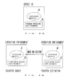
- Figs. 4A and 4B are diagrams for explaining the encapsulation of the facilities of an agent etc. and distributed object environments where the agent etc. operate, the facilities and the environments being included in an embodiment of the present invention, respectively.
- Fig. 4A illustrates the concept of the encapsulation.
- A
program module 41 contains programs for the processes which are executed by the agent themselves in each of the foregoing embodiments. Only theprogram module 41 may exist in a case where it is installed in the terminal or the gateway and lies in an operable state. - Herein, however, a
program operation environment 42 for the operation of theprogram module 41 is put together with thisprogram module 41 and is constructed as one object beforehand. Thus, in case of running theprogram module 41, theprogram operation environment 42 is first started to set the environment where theprogram module 41 can operate. - A
capsule 40 in which theprogram module 41 is combined with theprogram operation environment 42 as stated above, is used as a transfer unit. Accordingly, even in a case where the destination of transfer does not have the operating environment of theprogram module 41, the environment where theprogram module 41 is operable can be set by running thecapsule 40 so as to start thisprogram module 41. - In this manner, the "encapsulation of functions" signifies that a certain function is combined with an environment for the operation of the program so as to operate even solely. In a "telescript" by way of example, a program counter, a stack pointer, etc. are put together with a program. Such a contrivance is necessitated especially for moving the program which is operating.
- Fig. 4B illustrates a case where the distributed object environments are installed in the computer network.
- In the case where the computer network is furnished with the distributed object environments in this manner, naturally the terminals and the gateways are furnished with the distributed object environments. Accordingly, in a case where the agent to be run in each of the terminals and gateways is constructed beforehand so as to operate in the distributed object environment, it is dispensed with to transfer the
program operation environment 42 together with theprogram module 41 when thisprogram module 41 is moved, as in the expedient of Fig. 4A. With the expedient of Fig. 4B, accordingly, any program operation environment for the operation of theprogram module 41 need not be put together into a capsule in a case where a transfer source and a transfer destination include the distributedobject environments 43 in common and where the movement of theprogram module 41 during the operation thereof is not especially required. It is therefore possible that, as shown in Fig. 4B, only theprogram module 41 be transmitted from the transfer source to the transfer destination so as to operate in this transfer destination. - Fig. 5 is a block diagram showing the common constructions of a gateway, a client and a server each of which includes an agent for incarnating the function of controlling communication data, and the construction of an agent manager which controls such agents. (In the ensuing description down to Fig. 10, the terminal of the client shall be expressed merely as the "client".)
- The functions of controlling the communication data in the terminals (the terminal of the
client 11, and the terminals of theservers 10 and 20) and the gateways G1, G2 and G3 in the first to third embodiments are incarnated as encapsulated agent programs. The agents are managed by, for example, theagent manager 51 which exists in one server disposed in the computer network. - The gateway, client or
server 50 is constituted byagent reception unit 52,agent check unit 53, anagent platform 55 and an OS (operating system) 56. - The
agent reception unit 52 is unit for receiving theagent 59 which is transmitted from theagent manager 51. Theagent 59 received by theagent reception unit 52 is delivered to theagent check unit 53. Then, theagent check unit 53 decides whether or not the transmittedagent 59 is proper (or legal). In the event that theagent 59 is improper (or illegal), it is discarded. In contrast, on condition that theagent 59 is proper, it is delivered to theagent platform 55 being the operating environment thereof and is run as theagent 54. - The
agent platform 55 is constructed so as to operate on theOS 56. By way of example, in a case where the agent is constructed as an applet of Java, theagent platform 55 may be an environment where a WWW browser operates. - Likewise, the
agent 58 is also sent to and run in the gateway, client orserver 57. - The
agent manager 51 is installed in one server within the computer network as stated before. Thisagent manager 51 includesagent storage unit 61, in which the agents are stored. The locations of the agents are managed by an agent storage location management table 62. -
Operation unit 63 is comprised ofdiscrimination unit 64 andsearch unit 65. In a case where the agent needs to be transmitted to, e. g., the gateway, thediscrimination unit 64 judges the necessity of acquiring information on the structure of the network and requests thesearch unit 65 to search for the corresponding agent. Upon receiving the request, thesearch unit 65 refers to the agent storage location management table 62 in order to know where the agent to be transmitted is stored within theagent storage unit 61. Thediscrimination unit 64 receives the result of the reference, and issues a transmission command toagent transmission unit 60. Then, theagent transmission unit 60 reads out the corresponding agent from theagent storage unit 61 and transmits this agent to, e. g., the gateway. - When the
agents server agent manager 51 as a message, and are received by message transmission/reception unit 66. Subsequently, the message transmission/reception unit 66 extracts network information items from the received message and stores them in networkinformation memory unit 67. Further, information items indicating the sites of the respective agents are extracted from the network information items, and they are logged in an agent site management table 68. Besides, thediscrimination unit 64 fetches the network information from the networkinformation memory unit 67, and it commands theagent transmission unit 60 to transmit the agent to the gateway, client or server requiring the agent anew. - The
agent manager 51 acquires information on the network structure from the network by using, for example, the SNMP (Simple Network Management Protocol). Subsequently, theagent manager 51 computes an appropriate one of the gateways and terminals (the terminals of the client and server) from the acquired network structure information, and it transmits the agent to the computed constituent. Alternatively, the agents may be kept resident in the terminals (of the server and client) and the gateways beforehand. - The transmitted agent acquires the network information, such as bandwidth, of the network to which the pertinent gateway or terminal (of the client or server) is connected. As a concrete example, the agent transmits a dummy packet to the associated network and computes a time period since the time of the transmission till the time at which the dummy packet is received again, thereby to measure the transmission rate of the network.
- Besides, the agent of the client acquires the size and resolution of a terminal screen, resource priority levels, etc. As a concrete example, the acquisition of the information items is perform ed by loading data from a setting file of predetermined format (a file in which necessary information items are recorded in a predetermined form). The agent of the server acquires information on, e. g., to which network the server is connected.
- The agents of the gateways, server and client notify the
agent manager 51 of the corresponding network information items and their own sites. They also notify any other agent of the network information items and the sites in compliance with a request made -by the other agent. Theagent manager 51 further operates to add, delete and move the agents on the basis of such network information. - In the foregoing case of moving the communication control function or the properties, each of the gateways, server and client possesses the
agent platform 55 and theagent reception unit 52, and theagent manager 51 delivers the agents to the pertinent ones of the gateways and terminals (of the server and client). Incidentally, each of the gateways, server and client may also include agent transmission unit. Theagent platform 55 may well be a distributed object environment of, for example, CORBA (Common ORB Architecture), HORB, or Java RMI (Java Remote Method Invocation specification). In the distributed object environment, only part of the function module (method) can be delivered besides the transmission of the agent itself. - In order to find the optimal communication path between the two terminals (between the client and the server), information on the structure (topology) of the network is first acquired from the router (gateway) in the network. As a concrete example, it is acquired using the SNMP. The acquired information is combined with network information such as the bandwidth of a section extending between the gateways, the bandwidth being acquired by the agents which are arranged in these gateways. Thus, the optimal communication is found.
- Fig. 6 shows an example of the format of the agent site management table 68.
- The
agent manager 51 needs to manage the sites of individual agents for the purpose of adding, deleting and moving the agents in accordance with network information. It is the agent site management table 68 that is provided for the purpose. - In the
agent manager 51, by way of example, the identifier of each of the agents is expressed by a machine name, domain name and agent name, and it is managed by agent management No. - The site of each agent is expressed by, for example, an IP address and the agent management No. Accordingly, the agent site management table 68 is formed of, for example, a table which converts the identifier of each agent into the (IP address + agent management No.).
- In the example of Fig. 6, the identifiers of the agents each being composed of the (machine name + domain name + agent name) are entered in a
column 70, while the sites each being composed of the (IP address + agent management No.) are entered in acolumn 71 in correspondence with the identifiers. - By way of example, in the uppermost row of the table in Fig. 6, the
column 70 bears "machinel" as the machine name, "domain1" as the domain name and "agent1" as the agent name. On the other hand, thecolumn 71 bears "123.234.56.78" as the IP address and "111" as the agent management No. - Fig. 7 is a flowchart showing the process of the
agent manager 51. - The
agent manager 51 operates to receive network information from the agents of the gateways, server and client, to discriminate the optimal arrangement place or function of the agent in accordance with the sites of the agents and the type of the terminal in the presence of any change, to search theagent storage unit 61 for the required agent and fetch this agent, and to deliver the fetched agent to the optimal place. - First, when the
agent manager 51 is started, it waits the reception of any message from any of the agents at step S10. When any message has been received, whether or not the content of the message is the network information is judged at step S11. In a case where the message content is not the network information, another process based on the message content is executed. Here, since the process is not directly pertinent to the embodiment, it shall be omitted from this description. - In a case where the message content has been judged as the network information at step S11, whether or not the network information has undergone any change is judged at step S12. The judgement on the change of the network information can be made in such a way that the network information received in the last cycle is stored in the network
information memory unit 67, whereupon it is compared with the network information received anew. - On condition that the absence of the change of the network information has been judged at step S12, the processing flow returns to step S10, at which the
agent manager 51 waits the reception of any message. In contrast, on condition that the presence of the change of the network information has been judged at step S12, the processing flow advances to step S13, at which the optimal arrangement place or function of the agent is discriminated in accordance with the sites of the agents and the type of the terminal by thediscrimination unit 64. - When the agent to be transmitted has been discriminated, the agent storage location management table 62 is searched for the agent by the
search unit 65 at step S14. At step S15, the agent is fetched from theagent storage unit 61 by theagent transmission unit 60. Further, at step S16, the agent is transmitted to the desired place by theagent transmission unit 60. Thereafter, the processing flow returns to step S10. - Fig. 8 is a flowchart showing the process of the
discrimination unit 64 included in theagent manager 51. - The
agent manager 51 receives the message from the agent by the message transmission/reception unit 66, and stores it in the networkinformation memory unit 67. Thediscrimination unit 64 judges whether or not the network information stored in the networkinformation memory unit 67 is of the client, at step S17. Subject to the client's network information, whether or not the client has roamed is judged at step S18. In a case where the client has not roamed, another process is executed. Here, since the other process is not directly pertinent to the embodiment, it shall be omitted from description. - In a case where the roaming of the client has been judged at step S18, information on the network is fetched from the network
information memory unit 67, and the gateway nearest to the place where the client lies currently is found (step S19). When the gateway nearest to the current place of the client has been found, whether or not the agent exists in this gateway is judged at step S20. The judgement is made by referring to the agent site management table 68. - In the presence of the agent in the particular gateway, the processing flow advances to step S22. On the other hand, in the absence of the agent, this agent stored in the
agent storage unit 61 is transmitted to the particular gateway through theagent transmission unit 60 at step S21, whereupon the processing flow advances to step S22. Here at step S22, a command is given for executing the data caching stated before by employing a memory not shown in Fig. 5. Thereafter, the processing flow returns to the step S17, at which thediscrimination unit 64 stands by for the next processing. - Meanwhile, when it has been judged at step S17 that the agent having sent the message is not of the client, the processing flow advances to step S23, which serves to judge whether or not the message has been sent from the agent which is installed in the server transmitting an image. In case of the judgement that the message is not of the image transmitting server, another process corresponding to the content of the message is executed. Here, since the process is not directly pertinent to the embodiment, it shall be omitted from description.
- In case of the judgement at step S23 that the message is of the image transmitting server, the gateway nearest to the server is found in the same way as explained at step S19 (step S24). Subsequently, whether or not the agent exists in the found gateway is judged (step S25). In the presence of the agent in the particular gateway, the processing flow advances to step S27. On the other hand, in the absence of the agent in the particular gateway, this agent stored in the
agent storage unit 61 is transmitted to the particular gateway through theagent transmission unit 60 at step S26, whereupon the processing flow advances to step S27. - At step S27, a command is given for activating (or starting) the image converting function which is installed in the gateway. Thereafter, the processing flow returns to step S17. As stated before, the image converting function is a process which thins out pixels from image data or extracts only part of an image by utilizing any known technique.
- Fig. 9 is a flow chart for explaining an agent accepting process which is executed in each of the gateway, client and
server 50. - The process illustrated in Fig. 9 is performed by the
agent reception unit 52,agent check unit 53 andagent platform 55 which are shown in Fig. 5. - First, the
agent reception unit 52 receives the agent at step S28. Then, the received agent is temporarily stored at step S29. Subsequently, theagent check unit 53 checks the temporarily stored agent at step S30, and whether or not the agent is proper (or legal) is judged at step S31. - This step S31 is executed to judge whether or not the agent is one for a communication control as sent from the
agent manager 51 because what program is sent in as the agent, is not known. Without such processing, a virus etc. transmitted as the agent might be accepted. Therefore, the processing of step S31 is carried out. - In a case where the received agent has been judged improper (or illegal) at step S31, the
agent check unit 53 deletes this agent at step S32, followed by step S28 at which the reception of the next agent is waited by theagent reception unit 52. On the other hand, in a case where the received agent has been judged proper at step S31, this agent is activated (or started) under the operating environment of the agent platform 55 (step S33). Thereafter, the processing flow returns to step S28 so as to make ready for the reception of the next agent. - Fig. 10 is a flow chart showing the flow of a process in which image data to be transmitted from the server to the client are converted by the gateway.
- First, when the gateway has known from the network information etc. that the terminal of the client is incapable of satisfactorily displaying the image data to-be-received, it transmits a menu for image conversion to the terminal of the client at step S34. Then, the gateway waits the reception of a choice menu item from the client at step S35.
- When the choice menu item has been received from the client at step S35, whether or not the content of the choice menu item is the partial display of an image is judged at step S36. On condition that the choice menu item is the partial display of the image, the flow advances to step S37, at which part of the image data is transmitted to the client. Then, the process is ended.
- In contrast, on condition that the content of the choice menu item received at step S36 is not the partial display of the image, whether or not the content of the choice menu item is the scale-down display of the image is judged at step S38. Subject to the judgement that the content is not the scale-down display of the image, this content is decided to be an input which is not contained in the menu transmitted from the gateway, and a message which indicates the occurrence of an error in the menu item choice is transmitted to the client at step S46. Then, the flow returns to step S34 so as to the process from the transmission of the menu.
- Subject to the judgement at step S38 that the scale-down display of the image has been chosen, the image is scaled down at step S39. The image scaling-down may be performed by a known technique, and the pixels of the image are thinned out in accordance with a predetermined method by way of example. A scaled-down image is subsequently transmitted to the client at step S40, whereupon the process is ended.
- On the side of the client, the reception of the menu from the gateway is first awaited (step S41). Subsequently, when the menu has been received, it is displayed, and the user of the client is prompted to choose a menu item (step S42). At step S43, the input of the choice menu item by the user is awaited, and the choice menu item is transmitted to the gateway when input.
- At step S47, the reception of the message from the gateway is awaited for a predetermined time period. In a case where no message has been received in spite of the lapse of the predetermined time period at step S47, or where the message of the choice error from the gateway has been received thereat, the flow advances to step S48. This step S48 serves to judge whether or not the choice error message has been received. Subject to the reception of the choice error message, the flow returns to step S41 so as to repeat the process from the beginning.
- The judgement at step S48 that the choice error message has not been received, signifies that the menu item choice has been successful. The step S48 is therefore followed by step S44, at which the reception of the image data is awaited. When the image data have been received at step S44, the flow advances to step S45, at which the image is displayed.
- The above description of the embodiment has referred to the case where the menu of the image processing contains only the two menu items; the partial display of the image, and the scale-down display of the image. As another menu item, the monochromatic display of the image may well be added.
- In the description of the process shown in Fig. 10, it has been premised that the process is executed in the gateway which is-near to the terminal of the client. Another aspect of an embodiment may well be so constructed that the first gateway near the terminal of the client receives the choice of the menu item from the client and transmits the menu item to the second gateway near the server, and that the second gateway near the server executes the process such as image compression. With this contrivance, the amount of image data which are transferred through the network can be reduced to the required minimum.
- Fig. 11 is a diagram for explaining the fourth embodiment, this embodiment employing a virtual proxy server by which the client having roamed is treated as if he/she were accessing the same server.
- In Fig. 11, the same constituents as those in Figs. 1 - 3 bear the same reference numerals or symbols, and detailed explanation thereof shall be omitted from this description. Here, it is assumed that the terminal C1 of the
client 11 is a mobile terminal. - Usually, the Web browser of the
client 11 directly designates aproxy server 80 which has a cache function etc. The "proxy server" signifies a server (or gateway) to which theclient 11 is connected in accessing aserver 10 through a network. - In such a case, there is the problem that, when the terminal C1 of the
client 11 has roamed to alter its communication path, the optimal communication path is not guaranteed in accessing theproxy server 80. Therefore, thevirtual proxy server 81 is installed in order that an application such as the Web browser may designate thisvirtual proxy server 81. - Gateways G1 - Gi find the optimal communication path between the two terminals C2 and C1 (of the
server 10 and the client 11) on the basis of information items on these terminals and the situations of networks sensed, and the gateways transfer packets sent to thevirtual proxy server 81, to anactual proxy server 82. Thus, even when the application does not know the roaming of the terminal C1, it selects theoptimal proxy server - Fig. 12 is a block diagram for explaining a system architecture which serves to implement the facility of the virtual proxy server.
- It is assumed that the terminal C1 of the
client 11 first accesses theserver 10 through anetwork 1. The terminal C1 of theclient 11 includes aWWW browser 91, and avirtual proxy agent 92 which operates as a virtual proxy server. Thevirtual proxy agent 92 is an agent which has the same functions as those of an ordinary proxy server. When accessed from theWWW browser 91, thevirtual proxy agent 92 serves to connect lines so that the terminal C1 of theclient 11 may be permitted to communicate with aWWW server 96 through an access point (AP) 93, thenetwork 1, and aproxy agent 94 installed in the actual gateway. In this manner, in the case of incarnating the virtual proxy server facility, the agent (virtual proxy agent 92) having the same functions as those of the proxy server is installed in the terminal C1 of theclient 11. Thus, theWWW server 96 can be accessed from theWWW browser 91 without being conscious of the fact that the proxy server has changed on account of the roaming of theclient 11. - It is assumed here that the network to which the terminal C1 is connected has shifted from the
network 1 to anetwork 2 on account of the roaming of theclient 11. Then, thevirtual proxy agent 92 installed in the terminal C1 of theclient 11 detects the alteration of the access point from theAP 93 to an AP 97 and detects the alteration of a network structure. - Therefore, (1) the
virtual proxy agent 92 sends an inquiry about the structure of the network to theproxy agent 94 of the gateway G1 through the AP 97 as well as thenetwork 2. In a case where the gateway G1 does not possess network information locally, (2) theproxy agent 94 interrogates anagent manager 90 about the network information. As stated before, theagent manager 90 possesses information items on the networks. Therefore, (3) theagent manager 90 transfers the network structure information to theproxy agent 94. (4) The network structure information is sent from theproxy agent 94 to thevirtual proxy agent 92 through thenetwork 2 as well as the AP 97. Thevirtual proxy agent 92 judges whether or not the proxy server currently set (gateway G1) is optimal, by utilizing the functions as the proxy server. - Here, since the
client 11 has roamed, the gateway G1 is no longer the optimal proxy server. Therefore, (5) thevirtual proxy agent 92 finds the optimal proxy server (gateway G2 having a proxy agent 98) and accesses theserver 10 through this gateway G2. - In the above, the
proxy agents 94 and 98 indicate the functions of the respective gateways G1 and G2 being the proxy servers, as the agents. - Besides, in a case where the
virtual proxy agent 92 judges the gateway G2 to be the optimal proxy server, it utilizes the network structure information acquired from theagent manager 90 before. - As an alternative arrangement, the mapping between access points (specified by telephone Nos. by way of example) and the optimal gateways (proxy servers) in the cases of accessing the
server 10 by the use of the access pointsare prestored as a table or the like in the terminal C1 of theclient 11. When the client's terminal C1 has been connected to a certain one of the access points, the optimal gateway may well be found in view of the stored table so as to connect the terminal C1 to this gateway. - Fig. 13 is a flowchart showing the process of respective portions in the architecture which includes the virtual proxy server agent depicted in Fig. 12.
- The
virtual proxy agent 92 on the side of theclient 11 is first monitoring whether or not a connection-destination access point has changed, at step S50. Insofar as the access point does not change, step S50 is iterated. When the change of the access point has been detected at step S50, it is judged at step S51 whether or not the side of theclient 11 possesses the mapping information items between access points and host proxy servers (proxy servers which exist at positions nearer to theserver 10 or WWW server 20). In a case where the mapping information items are possessed, the processing flow advances to step S57, at which the setting of the host proxy server is altered on the basis of the mapping information items. - In case of the judgement at step S51 that the mapping information items are not possessed, an inquiry about network structure information items is sent to the proxy agent of the host proxy server at step S52. Thereafter, the client side stands by for the reception of the information items at step S53. When the network structure information items have been received, the nearest proxy server is searched for at step S54, and whether or not the proxy server currently set is the nearest proxy server is judged at step S55. In a case where the nearest proxy server is set, the setting of the proxy server need not be altered, and hence, the processing flow returns to step S50.
- In case of the judgement at step S55 that the proxy server currently set is not the nearest proxy server, the correspondence between the access point and the proxy server as found at step S54 is stored at step S56, and the setting of the host proxy server is altered to the pertinent proxy server at step S57.
- Meanwhile, the
proxy agent 94 on the side of the gateway G1 which was the nearest proxy server before the roaming of theclient 11 receives a message from thevirtual proxy agent 92 on the side of theclient 11 at step S58, and it judges at step S59 whether or not the message contains the request for the network structure information. - On condition that the message does not contain the request for the network structure information, a process designated by the message is executed. This process is indicated by "To another process" in Fig. 13. Since, however, the process is not directly relevant to this embodiment, it shall be omitted from description. On condition that the request for the network structure information has been judged at step S59, whether or not the information is possessed in the gateway G1 itself is judged at step S60.
- Subject to the judgement that the information is possessed, the possessed information is transmitted to the virtual proxy agent 92 (step S61), and the processing flow returns to step S58, at which the
proxy agent 94 stands by for the reception of a message. Subject to the judgement at step S60 that the information is not possessed, a request for the information is sent to theagent manager 90 at step S62. When the information has been received at step S63, the received network structure information is stored at step S64, whereupon the processing flow advances to step S61. At this step S61, the information is transmitted to thevirtual proxy agent 92 on the side of theclient 11. Then, the processing flow returns to step S58. - In the
agent manager 90, when a message has been received from theproxy agent 94 at step S65, whether or not the message contains the request for the network structure information is judged at step S66. In a case where the message does not contain the request for the network structure information, another process complying with the message is executed. Also here, "another process" shall be omitted from description. - Subject to the judgement at step S66 that the message contains the request for the network structure information, the network structure information already possessed or acquired anew is transmitted to the
proxy agent 94 at step S67. Thereafter, the processing flow returns to step S65, at which the reception of a message is awaited. - By means of the present invention, data communications are performed over a computer network in adaptation to the situations of terminals and the computer network, as well as the changes in those situations. It is therefore possible to attain such effects as the exchange of data appropriate for the terminals, the shortening of data communication time periods, and the increased number of users allowable in the computer network as a result of the shorter time periods for data communication.
Claims (30)
- A communication system for a computer network having different networks, comprising:agent means for communicating with one another, thereby to perform communication controls of communication data which are exchanged through the computer network;gateway means (G1, G2, G3) for connecting the different networks, each of said gateway means including agent platform means for accepting and running at least one of said agent means; andterminal means (10, 11) each including at least one of said agent means, for performing data communication through said computer network;wherein the first agent means run in the gateway means and the second agent means run in the terminal means acquire information on said terminal means and information on a situation of the connected network, as well as a change of the situation, respectively, and the first and second agent means communicate with each other, thereby to cooperate while exchanging the information items respectively acquired, whereby the data communication is performed in adaptation to situations of said terminal means and said computer network, as well as changes of the situations.
- A communication system for a computer network as defined in claim 1, further comprising:
agent manager means (51) for managing said agent means operating to sense the situations of said terminal means and said computer network, as well as the changes of said situations, and for arranging said agent means in the appropriate gateway means in accordance with the change of the situation of said computer network. - A communication system for a computer network as defined in claim 1 or 2, wherein when image data are to be transferred from one (10) of said terminal means to the other terminal means (11) through said computer network, said gateway means (G1, G2, G3) transmit only part of the received image data to said other terminal means (11) in a case where said first agent means run in said gateway means (G1, G2, G3) have acquired the situation that said other terminal means (11) cannot display all of said image data.
- A communication system for a computer network as defined in claim 1, 2, or 3, wherein when image data are to be transferred from one (10) of said terminal means to the other terminal means (11) through said computer network, said gateway means (G1, G2, G3) generate image data with pixel data of the received image data thinned out and transmit the generated image data of the thinned-out pixel data to said other terminal means (11) in a case where said first agent means run in said gateway means (G1, G2, G3) have acquired the situation that said other terminal means (11) cannot display all of said received image data.
- A communication system for a computer network as defined in any preceding claim, wherein:said terminal means (10, 11) includes virtual proxy agent means (92) having functions similar to those of each of said gateway means (G1, G2, G3), for specifying one of said gateway means nearest to an existing position of the terminal means and establishing a communication connection between the nearest gateway means and said terminal means; andsaid virtual proxy agent means (92) automatically switches said nearest gateway means to another of said gateway means nearest to a new existing position of said terminal means so as to establish a new communication connection, in a case where said terminal means has roamed until said nearest gateway means changes to the other gateway means.
- A communication system for a computer network as defined in any preceding claim, wherein each of said agent means of said terminal means and said gateway means is encapsulated, and such encapsulated agent means communicate with one another, thereby to perform the data communication controls through said computer network.
- A communication system for a computer network as defined in claim 6, further comprising movement means operating with roaming of said terminal means, for moving said agent means from the first gateway means with which said terminal means was communicating through said computer network before the roaming, to the second gateway means with which said terminal means communicates after said roaming.
- A communication system for a computer network as defined in claim 6 or 7, wherein said terminal means includes agent platform means (55) for running said agent means accepted through said computer network, thereby to perform the data communication control through the second gateway means by using said agent means.
- A communication system for a computer network as defined in claim 6 or 7, wherein said gateway means includes agent platform means (55) for running said agent means accepted through said computer network, thereby to perform the data communication control through the second gateway means by using said agent means.
- A communication system for a computer network as defined in claim 6 or 7, Wherein said terminal means includes:agent reception means (52) for receiving said agent means through said computer network; andagent platform means (55) for running the received agent means;the communication control being performed using said agent means.
- A communication system for a computer network as defined in claim 10, wherein said terminal means (10, 11) further includes agent check means (53) for checking whether said agent means received by said agent reception means (52) is proper agent means or improper agent means, for deleting the improper agent means, and for activating and operating the proper agent means by said agent platform means (55).
- A communication system for a computer network as defined in claim 6 or 7, wherein said gateway means (G1, G2, G3) includes:agent reception means (52) for receiving said agent means through said computer network; andagent platform means (55) for running the received agent means;the communication control being performed using said agent means (54).
- A communication system for a computer network as defined in claim 12, wherein said gateway means (G1, G2, G3) further includes agent check means (53) for checking whether said agent means (59) received by said agent reception means (52) is proper agent means or improper agent means, for deleting the improper agent means, and for activating and operating the proper agent means (54) by said agent platform means (55).
- A communication system for a computer network as defined in any preceding claim, wherein said gateway means (G1, G2, G3) adaptively process and convert the communication data passing therethrough, on the basis of the information items on the situations of said terminal means and said computer network, as well as the changes of said situations.
- A communication system for a computer network having different networks, comprising:gateway means (G1, G2, G3) for connecting the different networks; andterminal means (10, 11) for performing data communication via the computer network;wherein said gateway means (G1, G2, G3) notifies said terminal means (10, 11) of a situation and a change of the situation of the computer network, and said terminal means (10, 11) notifies said gateway means (G1, G2, G3) of information on said terminal means (10, 11) so that communication of the terminal means (10, 11) via the computer network is adapted to the situation and the change of the situation of the computer network.
- A communication system for a computer network according to claim 15, wherein
said terminal means (10, 11) comprises agent means for acquiring the information on said terminal means (10, 11) and notifying said gateway means (G1, G2, G3) of the information. - A communication system for a computer network according to claim 15, wherein
said gateway means (G1, G2, G3) comprises agent means for acquiring the situation and the change of the situation of the computer network. - A communication system for a computer network according to claim 16, wherein
said agent means is sent to and installed in said terminal means (10, 11) if necessary. - A communication system for a computer network according to claim 17, wherein
said agent means is sent to and installed in said gateway means (G1, G2, G3) if necessary. - A communication system for a computer network according to any of claims 15 to 19, wherein
when a first terminal means (10, 11) sends graphic data to a second terminal means (10, 11) via the computer network, said gateway means (G1, G2, G3) sends only a part of the graphic data to the second terminal means (10, 11) if said gateway means (G1, G2, G3) detects that the second terminal means (10, 11) cannot display all of the graphic data. - A communication system for a computer network according to any of claims 15 to 19, wherein
when a first terminal means (10, 11) sends graphic data to a second terminal means (10, 11) via the computer network, said gateway means (G1, G2, G3) sends reduced graphic data to the second terminal means (10, 11) if said gateway means (G1, G2, G3) detects that the second terminal means (10, 11) cannot display all of the graphic data. - A communication system for a computer network according to any of claims 15 to 21, wherein
said terminal means (10, 11) is movable and performs communication via said gateway means (G1, G2, G3) nearest to a place to which said terminal means (10, 11) is moved. - A communication system for a computer network according to any of claims 15 to 22, wherein
said gateway means (G1, G2, G3) adaptively process and convert communication data passing therethrough, on the basis of the information on the situation and the change of the situation of said terminal means (10, 11) and the computer network. - A terminal for performing communication via a computer network comprising different networks connected by gateways, comprising:interface means for performing communication via the computer network; andagent means for acquiring information on the computer network supplied from the gateways (G1, G2, G3), sending information on the terminal (10, 11) to the gateways (G1, G2, G3), and performing communication adaptively to a situation and a change of the situation of the computer network, and processing a capability of the terminal (10, 11).
- A terminal according to claim 24, further comprising virtual proxy agent means having the same function as the gateways (G1, G2, G3), for determining one of the gateways (G1, G2, G3) which is nearest to a place of the terminal (10, 11), and establishing a communication connection between the terminal (10, 11) and the one of the gateways (G1, G2, G3),
wherein said virtual proxy agent means automatically change a gateway (G1, G2, G3) to which the terminal (10, 11) is to be connected to another one of the gateways (G1, G2, G3) when a nearest gateway has changed to another one of the gateways because of a movement of the terminal (10, 11). - A gateway for forming a computer network by connecting different networks and enabling communication between terminals connected to the computer network, comprising:interface means for enabling communication between the terminals (10, 11) via the computer network; andmeans for acquiring information on the terminals (10, 11) supplied from the terminals, sending to the terminals (10, 11) a situation and a change of the situation of the computer network, and processing and converting data to be sent to the terminals (10, 11) on the basis of the situation and the change of the situation of the computer network, and a processing capability of the terminals (10, 11).
- A gateway according to claim 26, wherein
when said gateway (G1, G2, G3) sends graphic data to the terminals (10, 11), said gateway (G1, G2, G3) sends a part of the graphic data to the terminals (10, 11) if the terminals (10, 11) cannot display all of the graphic data. - A gateway according to claim 26, wherein
when said gateway (G1, G2, G3) sends graphic data to the terminals (10, 11), said gateway (G1, G2, G3) sends reduced graphic data to the terminals (10, 11) if the terminals (10, 11) cannot display all of the graphic data. - An agent installed in gateways and terminals composing a computer network, for controlling communication between the terminals, comprising:acquiring means for acquiring a situation and a change of the situation of the computer network if the agent is installed in the gateways (G1, G2, G3), and acquiring information on a terminal (10, 11) if the agent is installed in the terminals;sending means for sending information acquired by said acquiring means to another agent; andreceiving means for receiving information sent from another agent,wherein the agent adaptively controls communication between the terminals (10, 11) via the computer network according to a situation and a change of the situation of the computer network on the basis of information received by said receiving means and information acquired by said acquiring means.
- An agent according to claim 29, wherein
said agent connects a terminal (10, 11) to the computer network via a gateway which has become nearest to the terminal (10, 11) when a gateway (G1, G2, G3) nearest to the terminal (10, 11) has changed according to a movement of the terminal (10, 11).
Applications Claiming Priority (3)
| Application Number | Priority Date | Filing Date | Title |
|---|---|---|---|
| JP206742/97 | 1997-07-31 | ||
| JP20674297 | 1997-07-31 | ||
| JP9206742A JPH1155324A (en) | 1997-07-31 | 1997-07-31 | Communication system for computer network |
Publications (3)
| Publication Number | Publication Date |
|---|---|
| EP0895374A2 true EP0895374A2 (en) | 1999-02-03 |
| EP0895374A3 EP0895374A3 (en) | 2004-09-08 |
| EP0895374B1 EP0895374B1 (en) | 2007-01-10 |
Family
ID=16528357
Family Applications (1)
| Application Number | Title | Priority Date | Filing Date |
|---|---|---|---|
| EP98301849A Expired - Lifetime EP0895374B1 (en) | 1997-07-31 | 1998-03-12 | Communication system for a computer network |
Country Status (4)
| Country | Link |
|---|---|
| US (1) | US6085222A (en) |
| EP (1) | EP0895374B1 (en) |
| JP (1) | JPH1155324A (en) |
| DE (1) | DE69836847D1 (en) |
Cited By (7)
| Publication number | Priority date | Publication date | Assignee | Title |
|---|---|---|---|---|
| EP1089491A2 (en) * | 1999-09-30 | 2001-04-04 | Lucent Technologies Inc. | Method and apparatus for efficient network management using an active network mechanism |
| WO2001033784A1 (en) | 1999-11-01 | 2001-05-10 | Matsushita Electric Industrial Co., Ltd. | Method and apparatus for information transmission |
| WO2001067695A1 (en) * | 2000-03-06 | 2001-09-13 | Sony Electronics Inc. | System and method for efficiently performing data transfer operations |
| WO2002019653A2 (en) * | 2000-09-01 | 2002-03-07 | Ikimbo, Inc. | System and method for transferring files |
| WO2002052804A1 (en) * | 2000-12-27 | 2002-07-04 | Portalify Oy | Methods for information delivery in an information delivery system |
| WO2002067543A2 (en) * | 2001-02-15 | 2002-08-29 | General Bandwidth, Inc. | System and method for selecting a compression algorithm according to an available bandwidth |
| WO2014083994A1 (en) * | 2012-11-30 | 2014-06-05 | 日本電気株式会社 | Packet transfer control system and method |
Families Citing this family (69)
| Publication number | Priority date | Publication date | Assignee | Title |
|---|---|---|---|---|
| US6175857B1 (en) * | 1997-04-30 | 2001-01-16 | Sony Corporation | Method and apparatus for processing attached e-mail data and storage medium for processing program for attached data |
| JPH1185524A (en) * | 1997-09-05 | 1999-03-30 | Toshiba Corp | Device and method for processing information and recording medium recording information processing program |
| JP4187814B2 (en) * | 1997-12-19 | 2008-11-26 | 株式会社東芝 | Data management method and data management system for mobile agent, and recording medium on which the method is programmed and recorded |
| US6477563B1 (en) * | 1998-04-13 | 2002-11-05 | Kabushiki Kaisha Toshiba | Agent system and information processing method for same |
| US6675194B1 (en) * | 1998-05-05 | 2004-01-06 | Mitel Corporation | Handling different communications types by using agents to implement communication goal commands |
| JP3689564B2 (en) * | 1998-07-31 | 2005-08-31 | キヤノン株式会社 | OA device, OA system, control method, and storage medium |
| US6574239B1 (en) * | 1998-10-07 | 2003-06-03 | Eric Morgan Dowling | Virtual connection of a remote unit to a server |
| JP3935276B2 (en) * | 1998-10-21 | 2007-06-20 | キヤノン株式会社 | Network device management method, apparatus, storage medium, and transmission apparatus |
| EP1166521B1 (en) * | 1999-03-31 | 2004-07-28 | BRITISH TELECOMMUNICATIONS public limited company | Method of routing data |
| AU4979100A (en) * | 1999-06-03 | 2000-12-28 | Sycamore Networks, Inc. | Adaptive and scalable server control |
| US6339773B1 (en) * | 1999-10-12 | 2002-01-15 | Naphtali Rishe | Data extractor |
| JP2001117809A (en) * | 1999-10-14 | 2001-04-27 | Fujitsu Ltd | Media converting method and storage medium |
| JP3738624B2 (en) * | 1999-10-26 | 2006-01-25 | 日本電気株式会社 | Distributed application control system, control method, and recording medium recording program |
| FI112427B (en) * | 1999-11-05 | 2003-11-28 | Nokia Corp | A method for determining the capabilities of a wireless terminal in a multimedia messaging service, a multimedia messaging service, and a multimedia terminal |
| US6912586B1 (en) * | 1999-11-12 | 2005-06-28 | International Business Machines Corporation | Apparatus for journaling during software deployment and method therefor |
| JP3886309B2 (en) * | 1999-11-16 | 2007-02-28 | 日本電気株式会社 | Network management system and network management method |
| JP2001211197A (en) * | 2000-01-26 | 2001-08-03 | Nec Corp | Communication system, communication method, gateway device and client |
| JP2001222491A (en) * | 2000-02-09 | 2001-08-17 | Nec Corp | Information providing system, its method and client |
| CN1225117C (en) | 2000-03-14 | 2005-10-26 | 松下电器产业株式会社 | Device and method for reproducing image and voice |
| JP2001256097A (en) | 2000-03-14 | 2001-09-21 | Matsushita Electric Ind Co Ltd | System for automatically transmitting file |
| US7761554B1 (en) | 2000-03-22 | 2010-07-20 | International Business Machines Corporation | Method and system for designating required device attributes for embedding in a world-wide web document request |
| WO2001074046A1 (en) * | 2000-03-27 | 2001-10-04 | Sanyo Electric Co., Ltd. | Data distribution server, terminal, and data distribution system |
| WO2001080024A2 (en) * | 2000-04-17 | 2001-10-25 | Circadence Corporation | Gateway buffer prioritization |
| FI112307B (en) * | 2000-08-02 | 2003-11-14 | Nokia Corp | communication Server |
| JP2002077263A (en) * | 2000-09-04 | 2002-03-15 | Matsushita Electric Ind Co Ltd | Transmitting/receiving method |
| US6938087B1 (en) | 2000-09-12 | 2005-08-30 | Hewlett-Packard Development Company, L.P. | Distributed universal communication module for facilitating delivery of network services to one or more devices communicating over multiple transport facilities |
| FR2814571A1 (en) * | 2000-09-28 | 2002-03-29 | Eastman Kodak Co | METHOD FOR PROVIDING A CUSTOMER OF THE WEBSITE DESIGNER OR WEBSITE HOST A TOOL FOR TRANSFORMING AN IMAGE FROM A FIRST FORMAT INTO A SECOND FORMAT |
| US7349112B2 (en) | 2000-10-26 | 2008-03-25 | Matsushita Electric Industrial Co., Ltd. | Printing-object image designation device |
| JP2002152830A (en) * | 2000-11-10 | 2002-05-24 | Fujitsu Ltd | Mobile terminal and server for multimedia communication for conducting dynamic negotiation |
| US7082116B2 (en) * | 2000-12-28 | 2006-07-25 | Nortel Networks Limited | Methods and systems implementing mobility support in a packet-based wireless access network |
| JP2002232861A (en) * | 2001-01-30 | 2002-08-16 | Hitachi Ltd | Video information distributing device and operation device |
| WO2002075549A1 (en) * | 2001-03-16 | 2002-09-26 | Sharp Kabushiki Kaisha | Data synchronization system, apparatus used for the system, and data synchronization method |
| JP2002344913A (en) * | 2001-05-16 | 2002-11-29 | Nec Yonezawa Ltd | Conversion processing device and conversion processing method for video data in network, and conversion processing service |
| US7441007B1 (en) * | 2001-07-30 | 2008-10-21 | At&T Intellectual Property I, L.P. | System and method for allowing applications to retrieve properties and configuration information from a persistent store |
| US7191209B1 (en) * | 2001-07-30 | 2007-03-13 | Bellsouth Intellectual Property Corp. | Application server and method to perform hierarchical configurable data manipulation |
| US7353248B1 (en) * | 2001-07-30 | 2008-04-01 | At&T Delaware Intellectual Property, Inc. | Application server and method to perform hierarchical configurable data validation |
| JP2003076600A (en) * | 2001-08-30 | 2003-03-14 | Kddi Corp | Content distribution system and method and client terminal |
| US7343395B2 (en) * | 2002-03-29 | 2008-03-11 | Intel Corporation | Facilitating resource access using prioritized multicast responses to a discovery request |
| US8612196B2 (en) * | 2002-04-11 | 2013-12-17 | Linden Research, Inc. | System and method for distributed simulation in which different simulation servers simulate different regions of a simulation space |
| US7602795B1 (en) | 2002-08-20 | 2009-10-13 | Sprint Spectrum L.P. | Method and system for identifying a mobile station to a content server |
| EP1550019A4 (en) | 2002-09-16 | 2009-01-07 | Yahoo Inc | On-line software rental |
| US7616647B1 (en) | 2003-03-11 | 2009-11-10 | Sprint Spectrum L.P. | Method and system for wireless local number portability |
| US20050058112A1 (en) * | 2003-09-15 | 2005-03-17 | Sony Corporation | Method of and apparatus for adaptively managing connectivity for mobile devices through available interfaces |
| US8527611B2 (en) * | 2004-08-12 | 2013-09-03 | Telcordia Technologies, Inc. | Transparent service adaptation in heterogeneous environments |
| JP2006048707A (en) * | 2005-08-05 | 2006-02-16 | Matsushita Electric Ind Co Ltd | System for automatic transmission of file |
| US8130685B2 (en) | 2005-10-28 | 2012-03-06 | Nec Corporation | Mobile communication system, base station, mobile station, and power-saving transmission and reception method used in them |
| US8818757B2 (en) * | 2008-09-30 | 2014-08-26 | Rockwell Automation Technologies, Inc. | Modular object and host matching |
| US8078296B2 (en) * | 2006-09-29 | 2011-12-13 | Rockwell Automation Technologies, Inc. | Dynamic procedure selection |
| US9058032B2 (en) * | 2006-09-29 | 2015-06-16 | Rockwell Automation Technologies, Inc. | Hosting requirements for services |
| US7856279B2 (en) * | 2006-09-29 | 2010-12-21 | Rockwell Automation Technologies, Inc. | Module structure and use for industrial control systems |
| US7676279B2 (en) * | 2006-09-29 | 2010-03-09 | Rockwell Automation Technologies, Inc. | Services for industrial control systems |
| US8265775B2 (en) * | 2008-09-30 | 2012-09-11 | Rockwell Automation Technologies, Inc. | Modular object publication and discovery |
| US9217998B2 (en) * | 2006-09-29 | 2015-12-22 | Rockwell Automation Technologies, Inc. | Management and development of an industrial environment |
| US7912560B2 (en) * | 2006-09-29 | 2011-03-22 | Rockwell Automation Technologies, Inc. | Module and controller operation for industrial control systems |
| US7835805B2 (en) * | 2006-09-29 | 2010-11-16 | Rockwell Automation Technologies, Inc. | HMI views of modules for industrial control systems |
| US20080082577A1 (en) * | 2006-09-29 | 2008-04-03 | Rockwell Automation Technologies, Inc. | Module classification and searching for industrial control systems |
| US8041435B2 (en) * | 2008-09-30 | 2011-10-18 | Rockwell Automation Technologies, Inc. | Modular object dynamic hosting |
| US8732658B2 (en) * | 2006-09-29 | 2014-05-20 | Rockwell Automation Technologies, Inc. | Layered interface in an industrial environment |
| US8776092B2 (en) | 2006-09-29 | 2014-07-08 | Rockwell Automation Technologies, Inc. | Multiple interface support |
| US9261877B2 (en) * | 2006-09-29 | 2016-02-16 | Rockwell Automation Technologies, Inc. | Multiple machine interface |
| JP5419124B2 (en) | 2008-04-24 | 2014-02-19 | 日本電気株式会社 | Gateway device, communication method and program |
| JP2010206477A (en) * | 2009-03-03 | 2010-09-16 | Nec Corp | Content viewing system, gateway, content distribution method, and program |
| WO2014078365A1 (en) * | 2012-11-14 | 2014-05-22 | Raytheon Company | Network of networks architecture |
| JP6394591B2 (en) * | 2013-04-05 | 2018-09-26 | ソニー株式会社 | Control device, control method, computer program, and video transmission system |
| US20170316108A1 (en) * | 2014-11-11 | 2017-11-02 | Symmetric Co., Ltd. | Data processsing system, data processing device, and program for editing webpage |
| CN107370779B (en) * | 2016-05-12 | 2020-12-15 | 华为技术有限公司 | Data transmission method, device and system |
| JP6900853B2 (en) * | 2017-09-11 | 2021-07-07 | 日本電信電話株式会社 | Device linkage server and device linkage program |
| US10805384B1 (en) * | 2018-09-13 | 2020-10-13 | Parallels International Gmbh | Systems and methods for load balancing server infrastructure |
| US11310568B2 (en) * | 2020-05-05 | 2022-04-19 | Panasonic Avionics Corporation | Systems and methods for securely providing preview samples of media content distributed to in-flight entertainment systems |
Citations (2)
| Publication number | Priority date | Publication date | Assignee | Title |
|---|---|---|---|---|
| US5561769A (en) * | 1994-05-10 | 1996-10-01 | Lucent Technologies Inc. | Method and apparatus for executing a distributed algorithm or service on a simple network management protocol based computer network |
| US5638494A (en) * | 1994-03-15 | 1997-06-10 | Mitel Corporation | Adaptive communication system |
Family Cites Families (9)
| Publication number | Priority date | Publication date | Assignee | Title |
|---|---|---|---|---|
| US5499364A (en) * | 1993-10-14 | 1996-03-12 | Digital Equipment Corporation | System and method for optimizing message flows between agents in distributed computations |
| JPH07302236A (en) * | 1994-05-06 | 1995-11-14 | Hitachi Ltd | Information processing system, method therefor and service providing method in the information processing system |
| US5768506A (en) * | 1994-09-30 | 1998-06-16 | Hewlett-Packard Co. | Method and apparatus for distributed workflow building blocks of process definition, initialization and execution |
| US5655081A (en) * | 1995-03-08 | 1997-08-05 | Bmc Software, Inc. | System for monitoring and managing computer resources and applications across a distributed computing environment using an intelligent autonomous agent architecture |
| US5721908A (en) * | 1995-06-07 | 1998-02-24 | International Business Machines Corporation | Computer network for WWW server data access over internet |
| US5740368A (en) * | 1995-06-30 | 1998-04-14 | Canon Kabushiki Kaisha | Method and apparatus for providing information on a managed peripheral device to plural agents |
| US5850517A (en) * | 1995-08-31 | 1998-12-15 | Oracle Corporation | Communication link for client-server having agent which sends plurality of requests independent of client and receives information from the server independent of the server |
| US5790789A (en) * | 1996-08-02 | 1998-08-04 | Suarez; Larry | Method and architecture for the creation, control and deployment of services within a distributed computer environment |
| US6503054B1 (en) * | 2001-07-13 | 2003-01-07 | General Electric Company | Second-stage turbine nozzle airfoil |
-
1997
- 1997-07-31 JP JP9206742A patent/JPH1155324A/en active Pending
-
1998
- 1998-03-09 US US09/037,018 patent/US6085222A/en not_active Expired - Lifetime
- 1998-03-12 EP EP98301849A patent/EP0895374B1/en not_active Expired - Lifetime
- 1998-03-12 DE DE69836847T patent/DE69836847D1/en not_active Expired - Lifetime
Patent Citations (2)
| Publication number | Priority date | Publication date | Assignee | Title |
|---|---|---|---|---|
| US5638494A (en) * | 1994-03-15 | 1997-06-10 | Mitel Corporation | Adaptive communication system |
| US5561769A (en) * | 1994-05-10 | 1996-10-01 | Lucent Technologies Inc. | Method and apparatus for executing a distributed algorithm or service on a simple network management protocol based computer network |
Non-Patent Citations (2)
| Title |
|---|
| "ITU-T Recommendation H.323: Visual telephone systems and equiment for local area networks which provide a non-guaranteed quality of service" ITU-T H.323, XX, XX, November 1996 (1996-11), page COMPLETE, XP002227146 * |
| THOM G A: "H. 323: THE MULTIMEDIA COMMUNICATIONS STANDARD FOR LOCAL AREA NETWORKS" IEEE COMMUNICATIONS MAGAZINE, IEEE SERVICE CENTER. PISCATAWAY, N.J, US, vol. 34, no. 12, 1 December 1996 (1996-12-01), pages 52-56, XP000636454 ISSN: 0163-6804 * |
Cited By (16)
| Publication number | Priority date | Publication date | Assignee | Title |
|---|---|---|---|---|
| EP1089491A3 (en) * | 1999-09-30 | 2003-09-24 | Lucent Technologies Inc. | Method and apparatus for efficient network management using an active network mechanism |
| EP1089491A2 (en) * | 1999-09-30 | 2001-04-04 | Lucent Technologies Inc. | Method and apparatus for efficient network management using an active network mechanism |
| WO2001033784A1 (en) | 1999-11-01 | 2001-05-10 | Matsushita Electric Industrial Co., Ltd. | Method and apparatus for information transmission |
| EP1156631A1 (en) * | 1999-11-01 | 2001-11-21 | Matsushita Electric Industrial Co., Ltd. | Method and apparatus for information transmission |
| EP1156631A4 (en) * | 1999-11-01 | 2009-04-01 | Panasonic Corp | Method and apparatus for information transmission |
| CN1328892C (en) * | 1999-11-01 | 2007-07-25 | 松下电器产业株式会社 | Method and apparatus for information transmission |
| US6965604B1 (en) | 1999-11-01 | 2005-11-15 | Matsushita Electric Industrial Co., Ltd. | Method and apparatus for information transmission |
| WO2001067695A1 (en) * | 2000-03-06 | 2001-09-13 | Sony Electronics Inc. | System and method for efficiently performing data transfer operations |
| US7240099B2 (en) | 2000-03-06 | 2007-07-03 | Sony Corporation | System and method for efficiently performing data transfer operations |
| WO2002019653A2 (en) * | 2000-09-01 | 2002-03-07 | Ikimbo, Inc. | System and method for transferring files |
| WO2002019653A3 (en) * | 2000-09-01 | 2002-09-06 | Ikimbo Inc | System and method for transferring files |
| WO2002052804A1 (en) * | 2000-12-27 | 2002-07-04 | Portalify Oy | Methods for information delivery in an information delivery system |
| US6754221B1 (en) | 2001-02-15 | 2004-06-22 | General Bandwidth Inc. | System and method for selecting a compression algorithm according to an available bandwidth |
| WO2002067543A3 (en) * | 2001-02-15 | 2003-03-13 | Gen Bandwidth Inc | System and method for selecting a compression algorithm according to an available bandwidth |
| WO2002067543A2 (en) * | 2001-02-15 | 2002-08-29 | General Bandwidth, Inc. | System and method for selecting a compression algorithm according to an available bandwidth |
| WO2014083994A1 (en) * | 2012-11-30 | 2014-06-05 | 日本電気株式会社 | Packet transfer control system and method |
Also Published As
| Publication number | Publication date |
|---|---|
| EP0895374A3 (en) | 2004-09-08 |
| EP0895374B1 (en) | 2007-01-10 |
| US6085222A (en) | 2000-07-04 |
| JPH1155324A (en) | 1999-02-26 |
| DE69836847D1 (en) | 2007-02-22 |
Similar Documents
| Publication | Publication Date | Title |
|---|---|---|
| US6085222A (en) | Distributed communication system with adaptive data sending control in a computer network | |
| US6854014B1 (en) | System and method for accounting management in an IP centric distributed network | |
| US7388851B2 (en) | Proactive seamless service provisioning in mobile networks through transferring of application context | |
| CN100587681C (en) | System and method for communicating images between intercommunicating users | |
| US6483835B1 (en) | Communication system with communication route retrieval and selection function | |
| EP1662751B1 (en) | A data-cache apparatus and a data cache method used by a radio communications system | |
| JP2002368747A (en) | Network service for adaptive mobile application | |
| US20010013088A1 (en) | Information providing system, information providing method, and client apparatus | |
| US8019859B2 (en) | Reporting processing method, origin server and user client for user agent profile information | |
| EP1344417B1 (en) | Controlling service stream | |
| JP2004348494A (en) | Content distribution network | |
| JP2005229583A (en) | Network controller, communication terminal, and network selecting method | |
| US20020049800A1 (en) | Content retrieval device | |
| US20020031094A1 (en) | Communication system and method for determining user fee on the basis of quality of service | |
| EP2919509A1 (en) | Method and device for hosting application by access node | |
| US20050055466A1 (en) | Automatic network provisioning system | |
| Chan et al. | On realizing a broadband kernel for multimedia networks | |
| US20030187979A1 (en) | Method of and a system for data exchange over a data network such as the public internet | |
| Sun et al. | Adaptive connectivity management middleware for heterogeneous wireless networks | |
| EP1249119B1 (en) | Effective multilink flow handling | |
| KR101410510B1 (en) | Method and apparatus for data transferring using Stream Control Transfer Protocol | |
| CA2251175A1 (en) | System and method for efficient information transfer | |
| Anastasi et al. | An agent-based approach for QoS provisioning to mobile users in the Internet | |
| KR102169614B1 (en) | Method for application hosting by access node and apparatus therefor | |
| KR100726418B1 (en) | HTTP service method without login |
Legal Events
| Date | Code | Title | Description |
|---|---|---|---|
| PUAI | Public reference made under article 153(3) epc to a published international application that has entered the european phase |
Free format text: ORIGINAL CODE: 0009012 |
|
| AK | Designated contracting states |
Kind code of ref document: A2 Designated state(s): AT BE CH DE DK ES FI FR GB GR IE IT LI LU MC NL PT SE |
|
| AX | Request for extension of the european patent |
Free format text: AL;LT;LV;MK;RO;SI |
|
| PUAL | Search report despatched |
Free format text: ORIGINAL CODE: 0009013 |
|
| AK | Designated contracting states |
Kind code of ref document: A3 Designated state(s): AT BE CH DE DK ES FI FR GB GR IE IT LI LU MC NL PT SE |
|
| AX | Request for extension of the european patent |
Extension state: AL LT LV MK RO SI |
|
| RIC1 | Information provided on ipc code assigned before grant |
Ipc: 7H 04L 12/46 B Ipc: 7H 04L 12/24 A |
|
| 17P | Request for examination filed |
Effective date: 20050302 |
|
| 17Q | First examination report despatched |
Effective date: 20050411 |
|
| AKX | Designation fees paid |
Designated state(s): DE FR GB |
|
| GRAP | Despatch of communication of intention to grant a patent |
Free format text: ORIGINAL CODE: EPIDOSNIGR1 |
|
| GRAS | Grant fee paid |
Free format text: ORIGINAL CODE: EPIDOSNIGR3 |
|
| GRAA | (expected) grant |
Free format text: ORIGINAL CODE: 0009210 |
|
| RIN1 | Information on inventor provided before grant (corrected) |
Inventor name: IIDA, ICHIRO,C/O FUJITSU LIMITED Inventor name: TOKUYO, MASANAGA,C/O FUJITSU LIMITED Inventor name: FUJINO, NOBUTSUGU,C/O FUJITSU LIMITED |
|
| AK | Designated contracting states |
Kind code of ref document: B1 Designated state(s): DE FR GB |
|
| REG | Reference to a national code |
Ref country code: GB Ref legal event code: FG4D |
|
| REF | Corresponds to: |
Ref document number: 69836847 Country of ref document: DE Date of ref document: 20070222 Kind code of ref document: P |
|
| EN | Fr: translation not filed | ||
| PLBE | No opposition filed within time limit |
Free format text: ORIGINAL CODE: 0009261 |
|
| STAA | Information on the status of an ep patent application or granted ep patent |
Free format text: STATUS: NO OPPOSITION FILED WITHIN TIME LIMIT |
|
| 26N | No opposition filed |
Effective date: 20071011 |
|
| PG25 | Lapsed in a contracting state [announced via postgrant information from national office to epo] |
Ref country code: DE Free format text: LAPSE BECAUSE OF FAILURE TO SUBMIT A TRANSLATION OF THE DESCRIPTION OR TO PAY THE FEE WITHIN THE PRESCRIBED TIME-LIMIT Effective date: 20070411 |
|
| PG25 | Lapsed in a contracting state [announced via postgrant information from national office to epo] |
Ref country code: FR Free format text: LAPSE BECAUSE OF FAILURE TO SUBMIT A TRANSLATION OF THE DESCRIPTION OR TO PAY THE FEE WITHIN THE PRESCRIBED TIME-LIMIT Effective date: 20070831 |
|
| PG25 | Lapsed in a contracting state [announced via postgrant information from national office to epo] |
Ref country code: FR Free format text: LAPSE BECAUSE OF FAILURE TO SUBMIT A TRANSLATION OF THE DESCRIPTION OR TO PAY THE FEE WITHIN THE PRESCRIBED TIME-LIMIT Effective date: 20070110 |
|
| PGFP | Annual fee paid to national office [announced via postgrant information from national office to epo] |
Ref country code: GB Payment date: 20150311 Year of fee payment: 18 |
|
| GBPC | Gb: european patent ceased through non-payment of renewal fee |
Effective date: 20160312 |
|
| PG25 | Lapsed in a contracting state [announced via postgrant information from national office to epo] |
Ref country code: GB Free format text: LAPSE BECAUSE OF NON-PAYMENT OF DUE FEES Effective date: 20160312 |