EP0895274A1 - Illuminator and display utilizing the same - Google Patents
Illuminator and display utilizing the same Download PDFInfo
- Publication number
- EP0895274A1 EP0895274A1 EP97917437A EP97917437A EP0895274A1 EP 0895274 A1 EP0895274 A1 EP 0895274A1 EP 97917437 A EP97917437 A EP 97917437A EP 97917437 A EP97917437 A EP 97917437A EP 0895274 A1 EP0895274 A1 EP 0895274A1
- Authority
- EP
- European Patent Office
- Prior art keywords
- light
- heat source
- type heat
- heating type
- light source
- Prior art date
- Legal status (The legal status is an assumption and is not a legal conclusion. Google has not performed a legal analysis and makes no representation as to the accuracy of the status listed.)
- Withdrawn
Links
Images


Classifications
-
- G—PHYSICS
- G02—OPTICS
- G02B—OPTICAL ELEMENTS, SYSTEMS OR APPARATUS
- G02B6/00—Light guides; Structural details of arrangements comprising light guides and other optical elements, e.g. couplings
- G02B6/0001—Light guides; Structural details of arrangements comprising light guides and other optical elements, e.g. couplings specially adapted for lighting devices or systems
- G02B6/0011—Light guides; Structural details of arrangements comprising light guides and other optical elements, e.g. couplings specially adapted for lighting devices or systems the light guides being planar or of plate-like form
- G02B6/0013—Means for improving the coupling-in of light from the light source into the light guide
- G02B6/0023—Means for improving the coupling-in of light from the light source into the light guide provided by one optical element, or plurality thereof, placed between the light guide and the light source, or around the light source
- G02B6/0031—Reflecting element, sheet or layer
-
- G—PHYSICS
- G02—OPTICS
- G02B—OPTICAL ELEMENTS, SYSTEMS OR APPARATUS
- G02B6/00—Light guides; Structural details of arrangements comprising light guides and other optical elements, e.g. couplings
- G02B6/0001—Light guides; Structural details of arrangements comprising light guides and other optical elements, e.g. couplings specially adapted for lighting devices or systems
- G02B6/0011—Light guides; Structural details of arrangements comprising light guides and other optical elements, e.g. couplings specially adapted for lighting devices or systems the light guides being planar or of plate-like form
- G02B6/0066—Light guides; Structural details of arrangements comprising light guides and other optical elements, e.g. couplings specially adapted for lighting devices or systems the light guides being planar or of plate-like form characterised by the light source being coupled to the light guide
- G02B6/007—Incandescent lamp or gas discharge lamp
- G02B6/0071—Incandescent lamp or gas discharge lamp with elongated shape, e.g. tube
-
- G—PHYSICS
- G02—OPTICS
- G02B—OPTICAL ELEMENTS, SYSTEMS OR APPARATUS
- G02B6/00—Light guides; Structural details of arrangements comprising light guides and other optical elements, e.g. couplings
- G02B6/0001—Light guides; Structural details of arrangements comprising light guides and other optical elements, e.g. couplings specially adapted for lighting devices or systems
- G02B6/0011—Light guides; Structural details of arrangements comprising light guides and other optical elements, e.g. couplings specially adapted for lighting devices or systems the light guides being planar or of plate-like form
- G02B6/0081—Mechanical or electrical aspects of the light guide and light source in the lighting device peculiar to the adaptation to planar light guides, e.g. concerning packaging
-
- H—ELECTRICITY
- H01—ELECTRIC ELEMENTS
- H01J—ELECTRIC DISCHARGE TUBES OR DISCHARGE LAMPS
- H01J61/00—Gas-discharge or vapour-discharge lamps
- H01J61/02—Details
- H01J61/025—Associated optical elements
-
- H—ELECTRICITY
- H01—ELECTRIC ELEMENTS
- H01J—ELECTRIC DISCHARGE TUBES OR DISCHARGE LAMPS
- H01J61/00—Gas-discharge or vapour-discharge lamps
- H01J61/02—Details
- H01J61/52—Cooling arrangements; Heating arrangements; Means for circulating gas or vapour within the discharge space
-
- G—PHYSICS
- G02—OPTICS
- G02B—OPTICAL ELEMENTS, SYSTEMS OR APPARATUS
- G02B6/00—Light guides; Structural details of arrangements comprising light guides and other optical elements, e.g. couplings
- G02B6/0001—Light guides; Structural details of arrangements comprising light guides and other optical elements, e.g. couplings specially adapted for lighting devices or systems
- G02B6/0011—Light guides; Structural details of arrangements comprising light guides and other optical elements, e.g. couplings specially adapted for lighting devices or systems the light guides being planar or of plate-like form
- G02B6/0033—Means for improving the coupling-out of light from the light guide
- G02B6/005—Means for improving the coupling-out of light from the light guide provided by one optical element, or plurality thereof, placed on the light output side of the light guide
- G02B6/0055—Reflecting element, sheet or layer
Definitions
- This invention relates to a luminaire having a heater on the periphery of a low-pressure mercury lamp or other light sources, and a display using the luminaire.
- Luminaires of various types such as a direct-type back light type, an edge light type and so on, are used for liquid crystal displays in a dashboard on a vehicle, a vehicle navigation system and so on.
- Low-pressure mercury lamps are widely used as luminaires, using liquid crystal, in view of the advantages of; the luminous efficacy superior to a filament lamp, the smaller heat value, the long lasting use, a larger luminous area and uniform distribution of light in view of a long current discharge channel, and so on.
- the low-pressure mercury lamp is used in severe temperature conditions also. For example, when vehicles are driven in all areas and ranges of temperature, from 40°C in tropical zones, to -30°C below zero in frigid zones, the low-pressure mercury lamps used in the dashboard display, the vehicle navigation system and so on are also exposed under the above temperature conditions.
- the properties of the low-pressure mercury lamp are determined by the vapor pressure of mercury sealed inside, so that they are always under the influence of the ambient temperature. Especially, the beam of light and the starting characteristic are under the influence remarkably. More specifically, the radiation of wavelengths 254 nm and 185 nm are decreased in low-temperatures, so that the beam of light is decreased and dimmed; and it is also difficult to light due to the decrease in the partial pressure of the mercury vapor in relation to the sealed inert gas, therefore taking a long time to reach the specified luminance.
- the luminous efficacy reaches the maximum in the ambient temperature of approximately 40°C, so that the general low-pressure mercury lamp is preferably used in the range from 5°C to 40°C.
- the luminaire used in low temperature conditions is provided with a heater on the periphery of the low-pressure mercury lamp, in which the surface temperature of the low-pressure mercury lamp is controlled by various means.
- Conventional example 1 Japanese Patent Laid-open No. Hei7-43680
- a heater having a predetermined width and provided on the surface of a low-pressure mercury lamp lighting a liquid crystal; a temperature detecting means for detecting a temperature of the low-pressure mercury lamp; and a controller controlling the heater in accordance with the temperature of the low-pressure mercury lamp detected by the temperature detecting means.
- the controller is composed of: an inverter lighting the low-pressure mercury lamp; an inverter current source connected to the inverter; and a current source controlling means for controlling On/Off of the inverter current source in accordance with the temperature of the low-pressure mercury lamp.
- the heater is provided on the surface of the low-pressure mercury lamp to have the predetermined width, so that the heater shields the beam of light irradiated from the low-pressure mercury lamp, thus decreasing the amount of light irradiated onto the liquid crystal.
- the heater is controlled by the control circuit composed of the inverter, the inverter current source and the inverter current source controlling means, so that the thermal runaway of the heater is produced when the above control circuit is not operated correctly.
- the temperature of the heating elements heating the low-pressure mercury lamp is controlled by the PTC thermistor, so that the thermal runaway of the heater is produced when the PTC thermistor is not operated correctly.
- the auto-temperature-control heating element portion is tight attached to the general fluorescent lamp along the predetermined width, so that the heating portion shields the beam of light from the fluorescent lamp.
- the present invention is intended to attain the aforementioned object by providing a light reflecting layer between light source and a controllably auto-heating type heat source.
- a luminaire according to the present invention in which a controllable auto-heating type heat source is placed on the periphery of a light source, is characterized by including a light reflecting layer provided at least between the light source and the controllable auto-heating type heat source.
- the heat source is a controllable auto-heating type and so a temperature detecting means and a control circuit in order to control the heat source are not needed, thus avoiding the thermal runaway of the heat source.
- the light reflecting layer is provided between the light source and the controllable auto-heating type heat source, so that the light reflecting layer reflects the light irradiated from the light source, resulting in the small amount of the beam of light shielded by the controllable auto-heating type heat source.
- a translucent material having a larger thermal conductivity than that of air, may be provided between the light source and the light reflecting layer.
- the light reflecting layer satisfactorily reflects the light irradiated from the light source, thereby further decreasing the amount of the beam of light shielded by the controllable auto-heating type heat source.
- the light source may be formed to be a long sized shape; and the controllable auto-heating type heat source may have an electrode couple placed along the longitudinal direction of the light source.
- the electrode couple is placed along the longitudinal direction of the light source, so that the local heating does not occur in the longitudinal direction of the controllable auto-heating type heat source, thereby uniformly heating the light source.
- controllable auto-heating type heat source may have thermoplastic resin and conductive particles consisting of carbon black, and further have a heating element showing the positive temperature coefficient characteristics.
- the heating element assuredly has the positive temperature coefficient characteristics, so that the resistance value is not decreased in a high-temperature area, thereby effectively avoiding overheating of the heating element.
- the resistance temperature property of the controllable auto-heating type heat source may be designed to have a change in resistance value of more than 1.2 times, in a range between the temperature at the maximum luminous efficacy of the light source, and a temperature being 30°C higher than the temperature at the maximum luminous efficacy of the light source.
- the resistance value is increased when a temperature exceeds the temperature at the maximum luminous efficacy of the light source, so that the overheating of the heat element just after the maximum luminous efficacy of the light source has been reached can be avoided.
- the resistance temperature property of the controllable auto-heating type heat source may be defined so that resistance value at temperature at which the luminous efficacy of the light source reaches its maximum is less than ten times larger than resistance value at temperature minus 30°C.
- the resistance value of the heat source is small until the luminous efficacy of the light source reaches the maximum value, so that a great amount of electric current flows into the heating source until the luminous efficacy of the light source reaches the maximum value. Thereby increasing the heat value of the heat source.
- the resistance temperature property of the controllable auto-heating type heat source can be that the resistance value does not decrease at the temperatures ranging from a temperature at which the luminous efficacy of the light source reaches its maximum to a temperature which is 150°C higher than the temperature at which the luminous efficacy of the light source reaches its maximum.
- the controllable auto-heating type heat source may be abutted to the light source to be thermally associated.
- heat generated in the heat source is directly transferred to the light source, thus enhancing the heat efficiency for the light source.
- controllable auto-heating type heat source may be placed to be distant from the light source on the opposite side from which the light source irradiates light.
- the light source may be an approximately cylindrical shaped low-pressure mercury lamp, in which the width of the controllable auto-heating type heat source is less than half of the diameter of the low-pressure mercury lamp.
- the light source and the controllable auto-heating type heat source can be mutually adhered with a self-adhesive material.
- the thermal connection between the light source and the controllable auto-heating type heat source is achieved by simple means.
- the light source can be a bent low-pressure mercury lamp; and the controllable auto-heating type heat source can have pliability and be placed along the low-pressure mercury lamp.
- a display can be composed of the luminaire described thus far and a translucent type display panel illuminated by the luminaire, in which the translucent type display panel may be a liquid crystal panel.
- the display may be an edge-light type liquid crystal device having a light guiding plate guiding light from the luminaire, in which the controllable auto-heating type heat source may be placed on the opposite side of the light source from the light guiding plate.
- the display may be an edge-light type liquid crystal device having a light guiding plate guiding light from the luminaire, in which the controllable auto-heating type heat source may be adhered to the light source through a self-adhesive material having translucent in any one of two directions except for the other two directions of the side of the light guiding plate and the opposite side of the light source from the light guiding plate.
- the light guiding plate can be a transparent acrylic plate.
- the light reflecting layer may be composed of a reflective sheet covering the back face of the light guiding plate and the periphery of the light source.
- the reflective sheet can be made of white foaming polyethylene terephthalate.
- Fig. 1 to Fig. 3 show a display 1 according to the first embodiment of the present invention.
- the display 1 is an edge-light type vehicle navigation system including: a box-shaped casing 2 having a rectangular opening 2A on a side thereof; a liquid crystal panel 3 as a translucent type display panel provided to the opening 2A of the casing 2; a luminaire 4 lighting the liquid crystal panel 3; and a light guiding plate 5 made of a transparent acrylic plate, which guides the light from the luminaire 4 to the liquid crystal panel 3.
- the luminaire 4 is, in turn, composed of: two low-pressure mercury lamps 6 placed as a light source along vis-a-vis ends of the light guiding plate 5; a controllable auto-heating type heat source 7 provided on the opposite side of each of the low-pressure mercury lamps 6 from the light guiding plate 5; a first light reflecting layer 8 placed between the low-pressure mercury lamp 6 and the controllable auto-heating type heat source 7 to face the low-pressure mercury lamp 6; a second reflecting layer 9 laminated on the outer surface of the first reflecting layer 8 to sandwich the controllable auto-heating type heat source 7 between the layers 8 and 9; and an adhesive double coated tape 10 fixedly adhering the first reflecting layer 8 to the low-pressure mercury lamp 6.
- the low-pressure mercury lamp 6 is formed to be an approximately cylindrical shape of 2 mm to 6 mm in diameter, specifically, the low-pressure mercury lamp 6 is a cold cathode lamp or a hot cathode lamp.
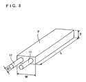
- Fig. 3 shows a specified structure of the controllable auto-heating type heat source 7.
- the controllable auto-heating type heat source 7 is a long, slender board-shaped heating element having two metallic core wires 11 covered with a heating composition, which has length L approximately corresponding to the length of the low-pressure mercury lamp 6, more specifically, from 50 mm to 400 mm, thickness T ranging from 0.3 mm to 0.8 mm, and width W ranging from 1 mm to 3 mm.
- the width W is less than half diameter d of the low-pressure mercury lamp 6.
- the two metallic core wires 11 works as an electrode couple which is placed along the longitudinal direction of the low-pressure mercury lamp 6, and each have diameter D ranging from 0.1 mm to 0.3 mm.
- the metallic core wire 11 is made of a metallic wire or a metallic tape, and formed to be a sectional circular shape as shown in the drawing, but it may be formed to be a sectional oval shape or a sectional square shape.
- the heating composition of the controllable auto-heating type heat source 7 consists of thermoplastic resin and conductive particles, and has the positive temperature coefficient characteristics (PTC characteristics) which shows resistance value increase with the rise in temperature.
- the heating composition which is formed by kneading the thermoplastic resin and the conductive particles, is extruded together with the metallic core wires 11.
- thermoplastic resin used here the crystalline thermoplastics is desirable, more specifically, polyolefin resin and copolymer resin thereof, a polyamide type resin, polyacetal resin, thermoplastic polyester resin, polyphenylene oxide, nonyl resin, polysulfone and so on can be listed.
- Respecting polyolefin resin for example, a polyethylene class such as a high-density polyethylene, a medium-density polyethylene, a low-density polyethylene, a linear low density polyethylene and so on; a polypropylene class such as isotactic polypropylene, syndiotactic polypropylene and so on; polybutene; 4-methylpentene-1 resin; and so on can be listed.
- a polyethylene class such as a high-density polyethylene, a medium-density polyethylene, a low-density polyethylene, a linear low density polyethylene and so on
- a polypropylene class such as isotactic polypropylene, syndiotactic polypropylene and so on
- polybutene 4-methylpentene-1 resin
- an ethylene acrylate type copolymer such as an ethylene propylene copolymer, an ethylene-vinyl acetate copolymer, an ethylene acrylic acid copolymer, an ethylene ethyl acrylate copolymer, an ethylene methyl acrylate copolymer and so on; a copolymer of olefin, such as an ethylene-vinyl chloride copolymer and so on, and a vinyl compound; a fluorine-containing ethylene type copolymer; and denatured substance of the aforementioned components.
- an ethylene acrylate type copolymer such as an ethylene propylene copolymer, an ethylene-vinyl acetate copolymer, an ethylene acrylic acid copolymer, an ethylene ethyl acrylate copolymer, an ethylene methyl acrylate copolymer and so on
- a copolymer of olefin such as an ethylene-vinyl chloride cop
- a vinyl acetate type resin for example, a vinyl acetate resin, polyvinyl acetoacetal, polyvinyl butyral and so on can be listed.
- Respecting polyamide resin for example, nylon 6, nylon 8, nylon 11, nylon 66, nylon 610 and so on can be listed.
- Polyacetal may either be a homopolymer or a copolymer.
- thermoplastic polyester resin for example, polyethylene terephthalate, polybutylene terephthalate and so on can be listed.
- thermoplastics in addition to the above list, for example, diene type polymer and copolymer, such as trans-1,3-polyisoprene, syndiotactic-1,2-polybutadiene, and so on can be listed.
- Each of the above crystalline thermoplastics may be used alone or as a polymer blend of more than two components.
- an olefin type copolymer such as a high-density polyethylene, a low-density polyethylene, a linear polyethylene or an ethylene-vinyl acetate copolymer, an ethylene ethyl acrylate copolymer and so on, trans-1,4-polyisoprene and so on are desirable.
- thermoplastics can be used as a composition with additives or another polymer as necessary.
- conductive particles described above for example, the following can be listed: particulate matter such as carbon black particles, graphite particles or the like; powder matter such as metallic powder, oxidised metal powder or the like; and fibered matter of carbon fiber or the like.
- particulate matter such as carbon black particles, graphite particles or the like is preferable, preferably, carbon black particles.
- Each of the conductive particles listed above can be used alone or in a mixture of two or more.
- a particle size of a conductive particle is not limited, but generally, the average particle size is, for example, 10 nm to 200 nm, preferably, 15 nm to 100 nm. Where the conductive particles are fiber, the aspect ratio is 1 to 1,000 generally, preferably, approximate 1 to 100.
- the proportion of a mixture of the crystalline resin and the conductive particles is generally 10-80:90-20 by weight percentage, preferably, 55-75:45-25.
- a proportion of conductive particles is below the above range, the resistance value of the controllable auto-heating type heat source 7 increases, so that the heat source 7 may not be sufficiently heated. But where a proportion of conductive particles exceeds the above range, the positive temperature coefficient characteristics do not sufficiently occur.
- a specific resistance value of the heating composition of the controllable auto-heating type heat source 7 can be appropriately selected in response to requirement or purpose, but in normal times, it is preferable to select 10 ⁇ cm to 50,000 ⁇ cm, more preferably, 40 ⁇ cm to 20,000 ⁇ cm.
- the cross-linking of the thermoplastic crystallinearesin can be carried out by using a crosslinking agent and/or radiation.
- the crosslinking agent can be appropriately selected from organic peroxide, a sulfur compound, an oxime group, a nitroso compound, an amine compound, a polyamine compound and so on in response to a type of the thermoplastic crystallinearesin.
- organic peroxide can be used as the suitable crosslinking agent.
- organic peroxide for example, the following is listed: benzoyl peroxide; lauroyl peroxide; dicumyl peroxide; tert-butyl peroxide; tert-butyl peroxy-benzoate; tert-butyl cumyl peroxide; 3-butyl hydro-peroxide; 2,5-dimethyl-2,5-di (tert-butyl peroxy) hexyne-3; 1,1-bis (tert-butyl peroxy isopropyl ) benzene; 1,1-bis(tert-butylperoxy)-3,3,5 - trimethyl cyclohexane; n-butyl-4,4-bis ( tert-butyl peroxy) valerate ; 2,2-bis (tert-butyl peroxy) butan
- each of the above organic peroxide can be used alone, and can be used with addition of a crosslinking ancillary agent, such as triallyl cyanurate, di-vinyl-benzene, triallyl isocyanurate and so on, as necessary.
- a crosslinking ancillary agent such as triallyl cyanurate, di-vinyl-benzene, triallyl isocyanurate and so on, as necessary.
- the proportions of the organic peroxide in the crystalline resin is generally 0.01% to 5% by weight, preferably 0.05% to 2% by weight, compared to the crystalline resin by weight of 100%.
- the proportion decreases to less than 0.01% by weight easily result in insufficient crosslinking, thereby the positive temperature coefficient characteristics do not occur sufficiently, the resistance in a high-temperature area decreases, and so on.
- the proportion increases to more than 5% by weight results in over-crosslinking, thereby leading to deterioration of moldability and the positive temperature coefficient characteristics.
- Fig. 4 is a graph showing the relationship between an ambient temperature and relative luminance of the low-pressure mercury lamp 6, of which luminance is 100% when the ambient temperature is 20°C. From the graph, it is understood that the luminous efficacy of the low-pressure mercury lamp 6 reaches the maximum value MAX when the ambient temperature is 40°C.
- Fig. 5 is a graph showing the relationship between the resistance values and the temperature of the controllable auto-heating type heat source 7. From the graph, it is understood that the controllable auto-heating type heat source 7 has the positive temperature coefficient characteristics which show that resistance value increases with the rise in the temperature.
- a change in resistance values (R 1 /R 0 ) is more than 1.2 times, preferably more than 4 times, more preferably more than 100 times, in the range between resistance value R 0 , which is shown in the temperature (40°C) at which the luminous efficacy of the low-pressure mercury lamp 6 reaches the maximum, and resistance value R 1 , which is shown in the temperature (70°C) which is 30°C higher than that of the resistance value R 0 .
- a change in resistance values (R 0 /R 2 ) is less than 10 times, preferably within twice, in the range from resistance value R 2 shown in the temperature -30°C to the resistance value R 0 which is shown in the temperature at which the luminous efficacy of the low-pressure mercury lamp 6 reaches the maximum.
- the first light reflecting layer 8 and the second light reflecting layer 9 are each composed of a reflective sheet which covers all of the back face of the light guiding plate 5, the peripheries of the two low-pressure mercury lamps 6, and a part of the front face of the light guiding plate 5.
- the light irradiated from the low-pressure mercury lamps 6 is irradiated onto the light guiding plate 5.
- the reflective sheet composing of the first light reflecting layer 8 is made of white foaming PET (polyethylene terephthalate), which has the thickness ranging from 0.05 mm to 0.2 mm.
- the reflective sheet composing of the second light reflecting layer 9 is made of white foaming PET (polyethylene terephthalate), which is thicker than the first light reflecting layer 8, more specifically, has the thickness ranging from 0.1 mm to 0.5 mm.
- the controllable auto-heating type heat source 7 is placed between the light reflecting layers 8 and 9, so that the first light reflecting layer 8 is formed to be an approximately angular-shape of which the top is on the side of the low-pressure mercury lamp 6.
- the light reflecting layers 8 and 9 may be mutually attached with an adhesive double coated tape.
- a laminated sheet can be formed by placing an EEA resin sheet or an LLDPE resin sheet as a thermal fusing layer onto the surface of the reflective sheet composing the first light reflecting layer 8, and then the light reflecting layers 8 and 9 can be mutually attached by thermally fusing the laminated sheet.
- At least one of the light reflecting layers 8 and 9 can be composed of an aluminium sheet or a silver sheet; or the first light reflecting layer 8 faced to the low-pressure mercury lamp 6 may be made of a white coating compound or a white forming resin.
- the adhesive double coated tape 10 is connected with the controllable auto-heating type heat source 7 and the low-pressure mercury lamp 6 to cause the heat source 7 and the lamp 6 to be thermally associated with each other through the first light reflecting layer 8.
- the tape 10 has width ranging from 0.5 mm to 2 mm and thickness ranging from 0.1 mm to 0.5 mm in order to decrease the area where it adheres to the low-pressure mercury lamp 6.
- the controllable auto-heating type heat source 7 is placed to have a distance from the low-pressure mercury lamp 6 for the thickness of the adhesive double coated tape 10.
- the adhesive double coated tape 10 is made of a material which has the effective transparence and a greater thermal conductivity than that of air, such as acrylic resin, silicone resin and so on.
- the adhesive double coated tape 10 works as a self-adhesive material and a translucent material.
- other adhesive materials of an acrylic type or a silicone type can be used as the self-adhesive material and the translucent material.
- the light is irradiated from the low-pressure mercury lamp 6 by electrifying the lamp 6.
- the light irradiated from the low-pressure mercury lamp 6 is directly sent to the light guiding plate 5, or sent to the light guiding plate 5 after reflecting from the light reflecting layers 8 and 9, and then reaches the liquid crystal panel 3 through the light guiding plate 5.
- the metallic core wire 11 of the controllable auto-heating type heat source 7 is electrified so that the low-pressure mercury lamp 6 is heated by the controllable auto-heating type heat source 7.
- the resistance value of the controllable auto-heating type heat source 7 is controlled to be relatively low until the temperature reaches the temperature (40°C) at which point the luminous efficacy of the low-pressure mercury lamp 6 reaches its maximum; so that the resistance value increases after the heat value increases and the temperature exceeds the temperature at the maximum luminous efficacy of the low-pressure mercury lamp 6, thereby controlling the heat value.
- the low-pressure mercury lamp 6 is placed to have a predetermined distance from the first light reflecting layer 8 without the adhesive double coated tape, but the other structures of this embodiment is the same as that of the first embodiment.
- a display 20 according to the second embodiment is an edge-light type vehicle navigation system which is composed of the casing 2 (see Fig. 1), the liquid crystal panel 3, a luminaire 24 lighting the liquid crystal panel 3, and the light guiding plate 5.
- the luminaire 24 is composed of the low-pressure mercury lamp 6, the controllable auto-heating type heat source 7 and the first and second light reflecting layers 8 and 9, in which a space is formed between the low-pressure mercury lamp 6 and the first light reflecting layer 8.
- the low-pressure mercury lamp 6 is placed at a different position on the light reflecting layers 8 and 9 from that in the first embodiment. But, the other structures of this embodiment are the same as that of the first embodiment.
- a display 30 is an edge-light type vehicle navigation system which is composed of the casing 2 (see Fig. 1), the liquid crystal panel 3, a luminaire 34 lighting the liquid crystal panel 3, and light guiding plate 5.
- the luminaire 34 is composed of the low-pressure mercury lamp 6, the controllable auto-heating type heat source 7, the first and second light reflecting layers 8 and 9, and the adhesive double coated tape 10.
- the controllable auto-heating type heat source 7 is fixedly adhered to the low-pressure mercury lamp 6 with the adhesive double coated tape 10 on a side in a direction excepting the two directions toward the side of the light guiding plate and the side opposite to the light guiding plate, namely, on a side in a direction perpendicular to the above two directions.
- the configurations of low-pressure mercury lamp, controllable auto-heating type heat source and light reflecting layers are different from that in the first embodiment. But the other structures of this embodiment are the same as that of the first embodiment.
- a display 40 of this embodiment is an edge-light type vehicle navigation system which is composed of the casing 2 (see Fig. 1), the liquid crystal panel 3, a luminaire 44 for lighting the liquid crystal panel 3, and the light guiding plate 5.
- the luminaire 44 is, in turn, composed of a low-pressure mercury lamp 46 bent in a C-shape; a controllable auto-heating type heat source 47 placed along the low-pressure mercury lamp 46; a first light reflecting layer 48 partially placed between the low-pressure mercury lamp 46 and the controllable auto-heating type heat source 47 and confronting the low-pressure mercury lamp 46; a second light reflecting layer 49 laminated on the outer surface of the first light reflecting layer 48, with the controllable auto-heating type heat source 47 being located between the light reflecting layers 48 and 49; and the adhesive double coated tape 10 fixedly adhering the first reflecting layer 48 to the low-pressure mercury lamp 46.
- the controllable auto-heating type heat source 47 has the same structure as the controllable auto-heating type heat source 7, but has pliability to be able to be placed along the low-pressure mercury lamp 46. Naturally, the electrode couple of the controllable auto-heating type heat source 47 is placed along the longitudinal direction of the low-pressure mercury lamp 46.
- the light reflecting layers 48 and 49 have the same structure as the light reflecting layers 8 and 9 but are placed along the C-shaped low-pressure mercury lamp 46.
- ethylene ethyl acrylate copolymer (EEA) and 40 wt% of carbon black are kneaded in a biaxial kneader to obtain pellet-shaped mixtures.
- 0.3 wt% relative to resin of Perhexyne25B is added as a crosslinking agent into the obtained pellet-shaped mixtures.
- the above pellet-shaped mixtures and two copper wires (metallic core wires) of 0.26 mm in diameter are co-extruded together by using the kneader to obtain a sectional rectangular shaped forming having the thickness T of 0.72 mm and the width W of 1 mm.
- the controllable auto-heating type heat source 7 is obtained by cutting the above forming in the length L of 15 cm.
- the first and second light reflecting layers 8 and 9 are each made of a sheet of white foaming PET and are mutually adhered with the adhesive double coated tape.
- a laminated sheet is formed by placing an EEA resin sheet or an LLDPE resin sheet as a thermally fusing layer onto the face of the reflecting sheet composing the first light reflecting layer 8, and then the light reflecting layers 8 and 9 are attached by thermally fusing the laminated sheets.
- the luminance of the low-pressure mercury lamp 6 is measured in the stable state in which the ambient temperature is 25°C. And, during the state in which the low-pressure mercury lamp 6 is lighted and the controllable auto-heating type heat source 7 is electrified in the ambient temperature is -30°C, the temperature of a tube-wall of the low-pressure mercury lamp 6 is measured after 60 seconds had elapsed since the lamp was lighted.
- Experiment 2 corresponds to the first embodiment, in which the specific structures of the controllable auto-heating type heat source 7 and the first and second light reflecting layers 8 and 9 are the same as that of Experiment 1.
- Experiment 3 corresponds to the third embodiment, in which the specific structures of the controllable auto-heating type heat source 7 and the first and second light reflecting layers 8 and 9 are the same as that of Experiment 1. But, the thickness of the adhesive double coating tape 10 adhering the first light reflecting layer 8 to the low-pressure mercury lamp 6 is defined to be 0.06 mm.
- Experiment 4 corresponds to the third embodiment, in which the specific structures of the controllable auto-heating type heat source 7 and the first and second light reflecting layers 8 and 9 are the same as that of Experiment 1. But, the thickness of the adhesive double coating tape 10 adhering the first light reflecting layer 8 to the low-pressure mercury lamp 6 is defined to be 0.4 mm.
- Comparison 1 A different point of Comparison 1 from the first embodiment is that the controllable auto-heating type heat source 7 or the other heaters are omitted.
- Comparison 1 the same measurement as that in Experiment 1. The results are shown in Table 1.
- the luminance in Comparison 1 is the highest in the stable state of the ambient temperature 25°C. This reason is that, in the ambient temperature 25°C, the low-pressure mercury lamp 6 is not affected in the low-temperature and most of the light irradiated from the low-pressure mercury lamp 6 is transferred to the light guiding plate 5 without being shielded. Therefore, concerning the comparison of luminance shown in Table 1, the value of Comparison 1 is defined as 100%.
- the light reflecting layers 8, 9, 48 and 49 are formed to be two layers in the embodiments, but in this invention it is sufficient that at least one light reflecting layer may be formed to attain the object of this invention.
- the aforementioned white coating compound or the like may be coated on a film made of a material non-reflecting light, such as dark-colored plastic, or the white foaming PET sheet may be laminated on the film.
- the requirement of the material of the layer is to reflect the light irradiated from the low-pressure mercury lamps 6 and 46.
- each of the controllable auto-heating type heat sources 7 and 47 includes two metallic core wires, but it can include more than three metallic core wires in this invention.
- a ceramic type PTC heater may be used as the controllable auto-heating type heat source.
- the display is defined as the edge-light type vehicle navigation system in the embodiments, but it may be a direct-type back light type vehicle navigation system, and may include any displays using liquid crystal, such as a vehicle meter, office automation products (e.g., a word processor, a personal computer or the like) and so on.
- the light source is not limited to the low-pressure mercury lamps 6 and 46.
- the controllable auto-heating type heat source is placed on the periphery of the light source and the light reflecting layer is placed between the light source and the controllable auto-heating type heat source, so that a temperature detecting means and a control circuit in order to control the heat source are not needed. Therefore, the heat source does not cause thermal runaway, and moreover, the light reflecting layer reflects the light irradiated from the light source, thereby allowing the amount of the beam of light shielded by the controllable auto-heating type heat source to be decreased.
- the present invention is convenient to be used for a display using liquid crystal, such as a vehicle meter, navigation system and so on.
Abstract
Description
- This invention relates to a luminaire having a heater on the periphery of a low-pressure mercury lamp or other light sources, and a display using the luminaire.
- Luminaires of various types, such as a direct-type back light type, an edge light type and so on, are used for liquid crystal displays in a dashboard on a vehicle, a vehicle navigation system and so on.
- Low-pressure mercury lamps are widely used as luminaires, using liquid crystal, in view of the advantages of; the luminous efficacy superior to a filament lamp, the smaller heat value, the long lasting use, a larger luminous area and uniform distribution of light in view of a long current discharge channel, and so on.
- The low-pressure mercury lamp is used in severe temperature conditions also. For example, when vehicles are driven in all areas and ranges of temperature, from 40°C in tropical zones, to -30°C below zero in frigid zones, the low-pressure mercury lamps used in the dashboard display, the vehicle navigation system and so on are also exposed under the above temperature conditions.
- The properties of the low-pressure mercury lamp are determined by the vapor pressure of mercury sealed inside, so that they are always under the influence of the ambient temperature. Especially, the beam of light and the starting characteristic are under the influence remarkably. More specifically, the radiation of wavelengths 254 nm and 185 nm are decreased in low-temperatures, so that the beam of light is decreased and dimmed; and it is also difficult to light due to the decrease in the partial pressure of the mercury vapor in relation to the sealed inert gas, therefore taking a long time to reach the specified luminance.
- The luminous efficacy reaches the maximum in the ambient temperature of approximately 40°C, so that the general low-pressure mercury lamp is preferably used in the range from 5°C to 40°C.
- Therefore, the luminaire used in low temperature conditions is provided with a heater on the periphery of the low-pressure mercury lamp, in which the surface temperature of the low-pressure mercury lamp is controlled by various means.
- As conventional luminaires, for example, there is Conventional example 1 (Japanese Patent Laid-open No. Hei7-43680), which is composed of: a heater having a predetermined width and provided on the surface of a low-pressure mercury lamp lighting a liquid crystal; a temperature detecting means for detecting a temperature of the low-pressure mercury lamp; and a controller controlling the heater in accordance with the temperature of the low-pressure mercury lamp detected by the temperature detecting means. In turn, the controller is composed of: an inverter lighting the low-pressure mercury lamp; an inverter current source connected to the inverter; and a current source controlling means for controlling On/Off of the inverter current source in accordance with the temperature of the low-pressure mercury lamp.
- In Conventional example 2 (Translated National Publication of Patent Application No. Hei7-501155; International Laid-open No. WO 93/10479), plural fluorescent lamps are arranged on a liquid crystal display, a thin-section type heating element is thermally coupled onto the opposite side of the low-pressure mercury lamp from the liquid crystal display, and the heating element is thermally coupled by a PTC thermistor, therefore the temperature of the heating element is controlled by the PTC thermistor.
- And further, in Conventional example 3 (Japanese Patent Laid-open No. Sho63-224140), an auto-temperature-control heating element portion having the positive temperature coefficient characteristics (PTC characteristics) is tight attached to an ordinary fluorescent lamp along a predetermined width.
- However, in Conventional example 1, the heater is provided on the surface of the low-pressure mercury lamp to have the predetermined width, so that the heater shields the beam of light irradiated from the low-pressure mercury lamp, thus decreasing the amount of light irradiated onto the liquid crystal.
- Furthermore, the heater is controlled by the control circuit composed of the inverter, the inverter current source and the inverter current source controlling means, so that the thermal runaway of the heater is produced when the above control circuit is not operated correctly.
- In Conventional example 2, the temperature of the heating elements heating the low-pressure mercury lamp is controlled by the PTC thermistor, so that the thermal runaway of the heater is produced when the PTC thermistor is not operated correctly.
- In Conventional example 3, the auto-temperature-control heating element portion is tight attached to the general fluorescent lamp along the predetermined width, so that the heating portion shields the beam of light from the fluorescent lamp.
- It is an object of the present invention to provide a luminaire capable of decreasing the amount of the beam of light shielded by heating source and avoiding thermal runaway of the heating source, and a display using the luminaire.
- The present invention is intended to attain the aforementioned object by providing a light reflecting layer between light source and a controllably auto-heating type heat source.
- More specifically, a luminaire according to the present invention, in which a controllable auto-heating type heat source is placed on the periphery of a light source, is characterized by including a light reflecting layer provided at least between the light source and the controllable auto-heating type heat source.
- In this invention described above, the heat source is a controllable auto-heating type and so a temperature detecting means and a control circuit in order to control the heat source are not needed, thus avoiding the thermal runaway of the heat source.
- Furthermore, the light reflecting layer is provided between the light source and the controllable auto-heating type heat source, so that the light reflecting layer reflects the light irradiated from the light source, resulting in the small amount of the beam of light shielded by the controllable auto-heating type heat source.
- In the present invention, a translucent material, having a larger thermal conductivity than that of air, may be provided between the light source and the light reflecting layer.
- For the above structure, the light reflecting layer satisfactorily reflects the light irradiated from the light source, thereby further decreasing the amount of the beam of light shielded by the controllable auto-heating type heat source.
- The light source may be formed to be a long sized shape; and the controllable auto-heating type heat source may have an electrode couple placed along the longitudinal direction of the light source.
- With the above structure, the electrode couple is placed along the longitudinal direction of the light source, so that the local heating does not occur in the longitudinal direction of the controllable auto-heating type heat source, thereby uniformly heating the light source.
- In the present invention, the controllable auto-heating type heat source may have thermoplastic resin and conductive particles consisting of carbon black, and further have a heating element showing the positive temperature coefficient characteristics.
- With the above structure, the heating element assuredly has the positive temperature coefficient characteristics, so that the resistance value is not decreased in a high-temperature area, thereby effectively avoiding overheating of the heating element.
- And, the resistance temperature property of the controllable auto-heating type heat source may be designed to have a change in resistance value of more than 1.2 times, in a range between the temperature at the maximum luminous efficacy of the light source, and a temperature being 30°C higher than the temperature at the maximum luminous efficacy of the light source.
- In the above structure, the resistance value is increased when a temperature exceeds the temperature at the maximum luminous efficacy of the light source, so that the overheating of the heat element just after the maximum luminous efficacy of the light source has been reached can be avoided.
- The resistance temperature property of the controllable auto-heating type heat source may be defined so that resistance value at temperature at which the luminous efficacy of the light source reaches its maximum is less than ten times larger than resistance value at
temperature minus 30°C. - In the above structure, the resistance value of the heat source is small until the luminous efficacy of the light source reaches the maximum value, so that a great amount of electric current flows into the heating source until the luminous efficacy of the light source reaches the maximum value. Thereby increasing the heat value of the heat source.
- And, the resistance temperature property of the controllable auto-heating type heat source can be that the resistance value does not decrease at the temperatures ranging from a temperature at which the luminous efficacy of the light source reaches its maximum to a temperature which is 150°C higher than the temperature at which the luminous efficacy of the light source reaches its maximum.
- In the above structure, even when the luminaire is used in extremely high temperatures, the heat source is prevented from overheating.
- The controllable auto-heating type heat source may be abutted to the light source to be thermally associated.
- In the above structure, heat generated in the heat source is directly transferred to the light source, thus enhancing the heat efficiency for the light source.
- And, the controllable auto-heating type heat source may be placed to be distant from the light source on the opposite side from which the light source irradiates light.
- In the above structure, although the heat source is placed on the periphery of the light source, the decrease of the light reflection efficiency is smaller, and hence the unquestionable decrease of the amount of the beam of light shielded by the heat source.
- The light source may be an approximately cylindrical shaped low-pressure mercury lamp, in which the width of the controllable auto-heating type heat source is less than half of the diameter of the low-pressure mercury lamp.
- In the above structure, it is possible to decrease the amount of the beam of the low-pressure mercury lamp which is shielded by the heat source.
- The light source and the controllable auto-heating type heat source can be mutually adhered with a self-adhesive material.
- In the above structure, the thermal connection between the light source and the controllable auto-heating type heat source is achieved by simple means.
- And further, the light source can be a bent low-pressure mercury lamp; and the controllable auto-heating type heat source can have pliability and be placed along the low-pressure mercury lamp.
- With the above structure, it is possible to place the heat source to correspond with the specified configuration of the low-pressure mercury lamp, thus allowing the low-pressure mercury lamp to be satisfactorily heated regardless its configuration.
- And further, in the present invention, a display can be composed of the luminaire described thus far and a translucent type display panel illuminated by the luminaire, in which the translucent type display panel may be a liquid crystal panel.
- The display may be an edge-light type liquid crystal device having a light guiding plate guiding light from the luminaire, in which the controllable auto-heating type heat source may be placed on the opposite side of the light source from the light guiding plate.
- Or the display may be an edge-light type liquid crystal device having a light guiding plate guiding light from the luminaire, in which the controllable auto-heating type heat source may be adhered to the light source through a self-adhesive material having translucent in any one of two directions except for the other two directions of the side of the light guiding plate and the opposite side of the light source from the light guiding plate.
- In this invention, the light guiding plate can be a transparent acrylic plate.
- The light reflecting layer may be composed of a reflective sheet covering the back face of the light guiding plate and the periphery of the light source.
- And further, the reflective sheet can be made of white foaming polyethylene terephthalate.
-
- Fig. 1 is a perspectively cutaway view of a display according to the first embodiment of the present invention;
- Fig. 2 is a fragmentary sectional view of the main part of Fig. 1;
- Fig. 3 is a perspective view showing a controllable auto-heating type heat source;
- Fig. 4 is a graph showing the relationship between an ambient temperature and relative luminance of a low-pressure mercury lamp;
- Fig. 5 is a graph showing the relationship between the resistance values and the temperature of the controllable auto-heating type heat source;
- Fig. 6 is a fragmentary sectional view of the display according to the second embodiment of the present invention;
- Fig. 7 is a fragmentary sectional view of the display according to the third embodiment of the present invention; and
- Fig. 8 is a perspectively cutaway view of the display according to the fourth embodiment of the present invention
-
- The preferred embodiments according to the present invention will be described below with reference to the attached drawings. In the description of the following embodiments, the same reference numerals and symbols will be used to designate the same or corresponding components as those in each embodiment, so that the description will be omitted or simplified.
- Fig. 1 to Fig. 3 show a display 1 according to the first embodiment of the present invention.
- In Fig. 1 and Fig. 2 showing the entire structure, the display 1 is an edge-light type vehicle navigation system including: a box-shaped
casing 2 having arectangular opening 2A on a side thereof; aliquid crystal panel 3 as a translucent type display panel provided to theopening 2A of thecasing 2; a luminaire 4 lighting theliquid crystal panel 3; and alight guiding plate 5 made of a transparent acrylic plate, which guides the light from the luminaire 4 to theliquid crystal panel 3. - The luminaire 4 is, in turn, composed of: two low-
pressure mercury lamps 6 placed as a light source along vis-a-vis ends of thelight guiding plate 5; a controllable auto-heatingtype heat source 7 provided on the opposite side of each of the low-pressure mercury lamps 6 from thelight guiding plate 5; a firstlight reflecting layer 8 placed between the low-pressure mercury lamp 6 and the controllable auto-heatingtype heat source 7 to face the low-pressure mercury lamp 6; a second reflectinglayer 9 laminated on the outer surface of the first reflectinglayer 8 to sandwich the controllable auto-heatingtype heat source 7 between thelayers tape 10 fixedly adhering the first reflectinglayer 8 to the low-pressure mercury lamp 6. - The low-
pressure mercury lamp 6 is formed to be an approximately cylindrical shape of 2 mm to 6 mm in diameter, specifically, the low-pressure mercury lamp 6 is a cold cathode lamp or a hot cathode lamp. - Fig. 3 shows a specified structure of the controllable auto-heating
type heat source 7. - In Fig. 3, the controllable auto-heating
type heat source 7 is a long, slender board-shaped heating element having two metallic core wires 11 covered with a heating composition, which has length L approximately corresponding to the length of the low-pressure mercury lamp 6, more specifically, from 50 mm to 400 mm, thickness T ranging from 0.3 mm to 0.8 mm, and width W ranging from 1 mm to 3 mm. The width W is less than half diameter d of the low-pressure mercury lamp 6. - The two metallic core wires 11 works as an electrode couple which is placed along the longitudinal direction of the low-
pressure mercury lamp 6, and each have diameter D ranging from 0.1 mm to 0.3 mm. - The metallic core wire 11 is made of a metallic wire or a metallic tape, and formed to be a sectional circular shape as shown in the drawing, but it may be formed to be a sectional oval shape or a sectional square shape.
- The heating composition of the controllable auto-heating
type heat source 7 consists of thermoplastic resin and conductive particles, and has the positive temperature coefficient characteristics (PTC characteristics) which shows resistance value increase with the rise in temperature. - In the fabrication of the controllable auto-heating
type heat source 7, the heating composition, which is formed by kneading the thermoplastic resin and the conductive particles, is extruded together with the metallic core wires 11. - Concerning the thermoplastic resin used here, the crystalline thermoplastics is desirable, more specifically, polyolefin resin and copolymer resin thereof, a polyamide type resin, polyacetal resin, thermoplastic polyester resin, polyphenylene oxide, nonyl resin, polysulfone and so on can be listed.
- Respecting polyolefin resin, for example, a polyethylene class such as a high-density polyethylene, a medium-density polyethylene, a low-density polyethylene, a linear low density polyethylene and so on; a polypropylene class such as isotactic polypropylene, syndiotactic polypropylene and so on; polybutene; 4-methylpentene-1 resin; and so on can be listed.
- In the first embodiment, the following can be used: an ethylene acrylate type copolymer such as an ethylene propylene copolymer, an ethylene-vinyl acetate copolymer, an ethylene acrylic acid copolymer, an ethylene ethyl acrylate copolymer, an ethylene methyl acrylate copolymer and so on; a copolymer of olefin, such as an ethylene-vinyl chloride copolymer and so on, and a vinyl compound; a fluorine-containing ethylene type copolymer; and denatured substance of the aforementioned components.
- In the above description, as to a vinyl acetate type resin, for example, a vinyl acetate resin, polyvinyl acetoacetal, polyvinyl butyral and so on can be listed.
- Respecting polyamide resin, for example,
nylon 6,nylon 8, nylon 11, nylon 66, nylon 610 and so on can be listed. - Polyacetal may either be a homopolymer or a copolymer.
- Concerning thermoplastic polyester resin, for example, polyethylene terephthalate, polybutylene terephthalate and so on can be listed.
- Concerning the crystalline thermoplastics, in addition to the above list, for example, diene type polymer and copolymer, such as trans-1,3-polyisoprene, syndiotactic-1,2-polybutadiene, and so on can be listed.
- Each of the above crystalline thermoplastics may be used alone or as a polymer blend of more than two components.
- As the aforementioned components of the crystalline thermoplastics, an olefin type copolymer such as a high-density polyethylene, a low-density polyethylene, a linear polyethylene or an ethylene-vinyl acetate copolymer, an ethylene ethyl acrylate copolymer and so on, trans-1,4-polyisoprene and so on are desirable.
- The aforementioned components of crystalline thermoplastics can be used as a composition with additives or another polymer as necessary.
- Respecting the conductive particles described above, for example, the following can be listed: particulate matter such as carbon black particles, graphite particles or the like; powder matter such as metallic powder, oxidised metal powder or the like; and fibered matter of carbon fiber or the like. In the above list, particulate matter such as carbon black particles, graphite particles or the like is preferable, preferably, carbon black particles.
- Each of the conductive particles listed above can be used alone or in a mixture of two or more.
- A particle size of a conductive particle is not limited, but generally, the average particle size is, for example, 10 nm to 200 nm, preferably, 15 nm to 100 nm. Where the conductive particles are fiber, the aspect ratio is 1 to 1,000 generally, preferably, approximate 1 to 100.
- The proportion of a mixture of the crystalline resin and the conductive particles is generally 10-80:90-20 by weight percentage, preferably, 55-75:45-25. When a proportion of conductive particles is below the above range, the resistance value of the controllable auto-heating
type heat source 7 increases, so that theheat source 7 may not be sufficiently heated. But where a proportion of conductive particles exceeds the above range, the positive temperature coefficient characteristics do not sufficiently occur. - A specific resistance value of the heating composition of the controllable auto-heating
type heat source 7 can be appropriately selected in response to requirement or purpose, but in normal times, it is preferable to select 10 Ω·cm to 50,000 Ω·cm, more preferably, 40 Ω·cm to 20,000 Ω·cm. - The cross-linking of the thermoplastic crystallinearesin can be carried out by using a crosslinking agent and/or radiation. The crosslinking agent can be appropriately selected from organic peroxide, a sulfur compound, an oxime group, a nitroso compound, an amine compound, a polyamine compound and so on in response to a type of the thermoplastic crystallinearesin.
- For example, where the thermoplastic crystallinearesin is a polyolefin type resin or the like, organic peroxide can be used as the suitable crosslinking agent. As organic peroxide, for example, the following is listed: benzoyl peroxide; lauroyl peroxide; dicumyl peroxide; tert-butyl peroxide; tert-butyl peroxy-benzoate; tert-butyl cumyl peroxide; 3-butyl hydro-peroxide; 2,5-dimethyl-2,5-di (tert-butyl peroxy) hexyne-3; 1,1-bis (tert-butyl peroxy isopropyl ) benzene; 1,1-bis(tert-butylperoxy)-3,3,5 - trimethyl cyclohexane; n-butyl-4,4-bis ( tert-butyl peroxy) valerate ; 2,2-bis (tert-butyl peroxy) butane; tert-butyl peroxy benzene; and so on.
- In the above list, 2,5-dimethyl-2,5-di (tert-butyl peroxy) hexyne-3 and so on are especially desirable. Incidentally, each of the above organic peroxide can be used alone, and can be used with addition of a crosslinking ancillary agent, such as triallyl cyanurate, di-vinyl-benzene, triallyl isocyanurate and so on, as necessary.
- The proportions of the organic peroxide in the crystalline resin is generally 0.01% to 5% by weight, preferably 0.05% to 2% by weight, compared to the crystalline resin by weight of 100%. When the proportion decreases to less than 0.01% by weight easily result in insufficient crosslinking, thereby the positive temperature coefficient characteristics do not occur sufficiently, the resistance in a high-temperature area decreases, and so on. On the other hand, when the proportion increases to more than 5% by weight results in over-crosslinking, thereby leading to deterioration of moldability and the positive temperature coefficient characteristics.
- Fig. 4 is a graph showing the relationship between an ambient temperature and relative luminance of the low-
pressure mercury lamp 6, of which luminance is 100% when the ambient temperature is 20°C. From the graph, it is understood that the luminous efficacy of the low-pressure mercury lamp 6 reaches the maximum value MAX when the ambient temperature is 40°C. - Fig. 5 is a graph showing the relationship between the resistance values and the temperature of the controllable auto-heating
type heat source 7. From the graph, it is understood that the controllable auto-heatingtype heat source 7 has the positive temperature coefficient characteristics which show that resistance value increases with the rise in the temperature. - Concerning resistance temperature property of the controllable auto-heating
type heat source 7, a change in resistance values (R1/R0) is more than 1.2 times, preferably more than 4 times, more preferably more than 100 times, in the range between resistance value R0, which is shown in the temperature (40°C) at which the luminous efficacy of the low-pressure mercury lamp 6 reaches the maximum, and resistance value R1, which is shown in the temperature (70°C) which is 30°C higher than that of the resistance value R0. And further, a change in resistance values (R0/R2) is less than 10 times, preferably within twice, in the range from resistance value R2 shown in the temperature -30°C to the resistance value R0 which is shown in the temperature at which the luminous efficacy of the low-pressure mercury lamp 6 reaches the maximum. - In the resistance temperature property of the controllable auto-heating
type heat source 7, a change in resistance values does not show decrease within the range between the temperature (40°C) at the maximum luminous efficacy of the low-pressure mercury lamp 6 and the temperature (190°C) which is 150°C higher than the above temperature (40°C). - In Fig. 1 and Fig. 2, the first
light reflecting layer 8 and the secondlight reflecting layer 9 are each composed of a reflective sheet which covers all of the back face of thelight guiding plate 5, the peripheries of the two low-pressure mercury lamps 6, and a part of the front face of thelight guiding plate 5. The light irradiated from the low-pressure mercury lamps 6 is irradiated onto thelight guiding plate 5. - The reflective sheet composing of the first
light reflecting layer 8 is made of white foaming PET (polyethylene terephthalate), which has the thickness ranging from 0.05 mm to 0.2 mm. - The reflective sheet composing of the second
light reflecting layer 9 is made of white foaming PET (polyethylene terephthalate), which is thicker than the firstlight reflecting layer 8, more specifically, has the thickness ranging from 0.1 mm to 0.5 mm. - The controllable auto-heating
type heat source 7 is placed between thelight reflecting layers light reflecting layer 8 is formed to be an approximately angular-shape of which the top is on the side of the low-pressure mercury lamp 6. - The
light reflecting layers light reflecting layer 8, and then thelight reflecting layers - In the first embodiment, at least one of the
light reflecting layers light reflecting layer 8 faced to the low-pressure mercury lamp 6 may be made of a white coating compound or a white forming resin. - The adhesive double coated
tape 10 is connected with the controllable auto-heatingtype heat source 7 and the low-pressure mercury lamp 6 to cause theheat source 7 and thelamp 6 to be thermally associated with each other through the firstlight reflecting layer 8. Thetape 10 has width ranging from 0.5 mm to 2 mm and thickness ranging from 0.1 mm to 0.5 mm in order to decrease the area where it adheres to the low-pressure mercury lamp 6. As a result, the controllable auto-heatingtype heat source 7 is placed to have a distance from the low-pressure mercury lamp 6 for the thickness of the adhesive double coatedtape 10. - The adhesive double coated
tape 10 is made of a material which has the effective transparence and a greater thermal conductivity than that of air, such as acrylic resin, silicone resin and so on. In the embodiment, the adhesive double coatedtape 10 works as a self-adhesive material and a translucent material. Instead of thetape 10, other adhesive materials of an acrylic type or a silicone type can be used as the self-adhesive material and the translucent material. - In the first embodiment described thus far, the light is irradiated from the low-
pressure mercury lamp 6 by electrifying thelamp 6. The light irradiated from the low-pressure mercury lamp 6 is directly sent to thelight guiding plate 5, or sent to thelight guiding plate 5 after reflecting from thelight reflecting layers liquid crystal panel 3 through thelight guiding plate 5. - When the display 1 is used under the low temperature condition, the metallic core wire 11 of the controllable auto-heating
type heat source 7 is electrified so that the low-pressure mercury lamp 6 is heated by the controllable auto-heatingtype heat source 7. The resistance value of the controllable auto-heatingtype heat source 7 is controlled to be relatively low until the temperature reaches the temperature (40°C) at which point the luminous efficacy of the low-pressure mercury lamp 6 reaches its maximum; so that the resistance value increases after the heat value increases and the temperature exceeds the temperature at the maximum luminous efficacy of the low-pressure mercury lamp 6, thereby controlling the heat value. - Therefore, the following effects are listed in the first embodiment.
- 1) In the luminaire 4 of the display 1 using the liquid crystal, since the
controllable auto-heating
type heat source 7 is placed on the periphery of the low-pressure mercury lamp 6, a temperature detecting means and a control circuit for controlling theheat source 7 are unnecessary in view of theheat source 7 as the controllable auto-heating type, thus avoiding the thermal runaway of theheat source 7. - 2) The first and second
light reflecting layers pressure mercury lamp 6 and the controllable auto-heatingtype heat source 7, so that thelight reflecting layers pressure mercury lamp 6, and hence the amount of the beam of light shielded by the controllable auto-heatingtype heat source 7 decreases. - 3) The adhesive double coated
tape 10 as the translucent material having the higher thermal conductivity than air is placed between the low-pressure mercury lamp 6 and thelight reflecting layers light reflecting layers pressure mercury lamp 6, thereby further decreasing the amount of the beam of light shielded by the controllable auto-heatingtype heat source 7. - 4) The light source is the long-cylindrical shaped low-
pressure mercury lamp 6, and also the controllable auto-heatingtype heat source 7 has the electrode couple 11 located along the longitudinal direction of the low-pressure mercury lamp 6. Therefore, local heating does not occur along the longitudinal direction of the controllable auto-heatingtype heat source 7 by reason that the electrode couple 11 is placed along the longitudinal direction of the low-pressure mercury lamp 6, with the result that the low-pressure mercury lamp 6 is uniformly heated. - 5) The controllable auto-heating
type heat source 7 has the heat element which has the thermoplastic resin and the conductive particles including carbon black, and shows the positive temperature coefficient characteristics, so that the resistance value is not decreased in the high-temperature area by reason that the heating element itself has the positive temperature coefficient characteristics, thus effectively preventing theheat source 7 from overheating. - 6) The resistance temperature property of the controllable auto-heating
type heat source 7 is set as; resistance value at temperature (40°C) at which the luminous efficacy of the low-pressure mercury lamp 6 reaches its maximum, is more than 1.2 times larger than resistance value at temperature (70°C) which is 30°C higher than the above temperature (40°C); therefore resistance value increases when a temperature exceeds a temperature at which the luminous efficacy of the low-pressure mercury lamp 6 reaches its maximum; and thereby overheating of theheat source 7 just after the luminous efficacy of the low-pressure mercury lamp 6 has reached its maximum, can be prevented. - 7) The resistance temperature property of the controllable auto-heating
type heat source 7 is that the change in resistance value is less than 10 times in the range from -30°C to the temperature at the maximum luminous efficacy of the low-pressure mercury lamp 6, so that the resistance value of theheat source 7 is small up to the temperature at the maximum luminous efficacy of the low-pressure mercury lamp 6. As a result, a great amount of current flows into theheat source 7 until the luminous efficacy of the low-pressure mercury lamp 6 reaches the maximum, so that the heat value of theheat source 7 is allowed to be increased. Thereby rapidly starting the luminance of theliquid crystal panel 3. - 8) The resistance temperature property of the controllable auto-heating
type heat source 7 is that the change in resistance value does not show decrease in the range between the temperature at the maximum luminous efficacy of the low-pressure mercury lamp 6 and the temperature which is 150°C higher than the above temperature. Thereby avoiding the overheating of theheat source 7 even when the luminaire 4 is used under unusually high-temperatures. - 9) The controllable auto-heating
type heat source 7 is abutted to the low-pressure mercury lamp 6 to be thermally associated, so that heat generated in theheat source 7 is directly transferred into the low-pressure mercury lamp 6, thus enhancing the heating efficiency for the low-pressure mercury lamp 6. - 10) The controllable auto-heating
type heat source 7 is placed apart from the low-pressure mercury lamp 6 on the side opposite to the side which is irradiated by the low-pressure mercury lamp 6, so that the light reflective efficiency can be controlled to decrease by less than 10% although theheat source 7 is positioned around the low-pressure mercury lamp 6, therefore the amount of the beam of light which is shielded by theheat source 7 is surely decreased. - 11) Width W of the controllable auto-heating
type heat source 7 is defined as less than half of the diameter d of the low-pressure mercury lamp 6.
Therefore, although the beam of light generated by the low-pressure mercury lamp 6 is shielded by theheat source 7, the amount of the shielded light is decreased. - 12) The adhesive double coated
tape 10 functioning as the self-adhesive material adheres the low-pressure mercury lamp 6 to the controllable auto-heatingtype heat source 7, so that the thermal association between the low-pressure mercury lamp 6 and the controllable auto-heatingtype heat source 7 is achieved by simple means. - 13) The adhesive double coated
tape 10 is provided between the low-pressure mercury lamp 6 and thelight reflecting layers light reflecting layers pressure mercury lamp 6. Thus further decreasing the amount of the light shielded by the controllable auto-heatingtype heat source 7. -
- The second embodiment according to the present invention will be described below with reference to Fig. 6.
- In the second embodiment, what is differ from the first embodiment is that the low-
pressure mercury lamp 6 is placed to have a predetermined distance from the firstlight reflecting layer 8 without the adhesive double coated tape, but the other structures of this embodiment is the same as that of the first embodiment. - In Fig. 6 showing the fragmentary portion of the second embodiment, a
display 20 according to the second embodiment is an edge-light type vehicle navigation system which is composed of the casing 2 (see Fig. 1), theliquid crystal panel 3, aluminaire 24 lighting theliquid crystal panel 3, and thelight guiding plate 5. Theluminaire 24 is composed of the low-pressure mercury lamp 6, the controllable auto-heatingtype heat source 7 and the first and secondlight reflecting layers pressure mercury lamp 6 and the firstlight reflecting layer 8. - Therefore, the effects similar to the Effects 1 to 11 listed in the first embodiment are also listed in the second embodiment.
- The third embodiment of the present invention will be described below with reference to Fig. 7.
- In this embodiment, the low-
pressure mercury lamp 6 is placed at a different position on thelight reflecting layers - In Fig. 7 showing the fragmentary portion of the third embodiment, a
display 30 according to this embodiment is an edge-light type vehicle navigation system which is composed of the casing 2 (see Fig. 1), theliquid crystal panel 3, aluminaire 34 lighting theliquid crystal panel 3, andlight guiding plate 5. - Similar to the luminaire 4 of the first embodiment, the
luminaire 34 is composed of the low-pressure mercury lamp 6, the controllable auto-heatingtype heat source 7, the first and secondlight reflecting layers tape 10. The controllable auto-heatingtype heat source 7 is fixedly adhered to the low-pressure mercury lamp 6 with the adhesive double coatedtape 10 on a side in a direction excepting the two directions toward the side of the light guiding plate and the side opposite to the light guiding plate, namely, on a side in a direction perpendicular to the above two directions. - Therefore, the effects similar to the Effects 1 to 13 mentioned in the first embodiment are also listed in the third embodiment.
- The fourth embodiment according to this invention will be explained below with reference to Fig. 8.
- In the fourth embodiment, the configurations of low-pressure mercury lamp, controllable auto-heating type heat source and light reflecting layers are different from that in the first embodiment. But the other structures of this embodiment are the same as that of the first embodiment.
- In Fig. 8 showing whole structure of the fourth embodiment, a
display 40 of this embodiment is an edge-light type vehicle navigation system which is composed of the casing 2 (see Fig. 1), theliquid crystal panel 3, aluminaire 44 for lighting theliquid crystal panel 3, and thelight guiding plate 5. - The
luminaire 44 is, in turn, composed of a low-pressure mercury lamp 46 bent in a C-shape; a controllable auto-heatingtype heat source 47 placed along the low-pressure mercury lamp 46; a firstlight reflecting layer 48 partially placed between the low-pressure mercury lamp 46 and the controllable auto-heatingtype heat source 47 and confronting the low-pressure mercury lamp 46; a secondlight reflecting layer 49 laminated on the outer surface of the firstlight reflecting layer 48, with the controllable auto-heatingtype heat source 47 being located between thelight reflecting layers tape 10 fixedly adhering the first reflectinglayer 48 to the low-pressure mercury lamp 46. - The controllable auto-heating
type heat source 47 has the same structure as the controllable auto-heatingtype heat source 7, but has pliability to be able to be placed along the low-pressure mercury lamp 46. Naturally, the electrode couple of the controllable auto-heatingtype heat source 47 is placed along the longitudinal direction of the low-pressure mercury lamp 46. - The
light reflecting layers light reflecting layers pressure mercury lamp 46. - Therefore, the effects similar to the Effects 1 to 13 listed in the first embodiment are also listed in the fourth embodiment.
- Next, Experiments will be explained below in order to confirm the effects of the first to the third embodiments.
- 60 wt% of an ethylene ethyl acrylate copolymer (EEA) and 40 wt% of carbon black are kneaded in a biaxial kneader to obtain pellet-shaped mixtures. 0.3 wt% relative to resin of Perhexyne25B is added as a crosslinking agent into the obtained pellet-shaped mixtures.
- The above pellet-shaped mixtures and two copper wires (metallic core wires) of 0.26 mm in diameter are co-extruded together by using the kneader to obtain a sectional rectangular shaped forming having the thickness T of 0.72 mm and the width W of 1 mm. The controllable auto-heating
type heat source 7 is obtained by cutting the above forming in the length L of 15 cm. - The first and second
light reflecting layers light reflecting layer 8, and then thelight reflecting layers - The structures of the low-
pressure mercury lamp 6, theheat source 7 and thelight reflecting layers - In Experiment 1 described thus far, the luminance of the low-
pressure mercury lamp 6 is measured in the stable state in which the ambient temperature is 25°C. And, during the state in which the low-pressure mercury lamp 6 is lighted and the controllable auto-heatingtype heat source 7 is electrified in the ambient temperature is -30°C, the temperature of a tube-wall of the low-pressure mercury lamp 6 is measured after 60 seconds had elapsed since the lamp was lighted. - The results are shown in Table 1.
-
Experiment 2 corresponds to the first embodiment, in which the specific structures of the controllable auto-heatingtype heat source 7 and the first and secondlight reflecting layers - In
Experiment 2, the same measurement as that in Experiment 1. The results are shown in Table 1. -
Experiment 3 corresponds to the third embodiment, in which the specific structures of the controllable auto-heatingtype heat source 7 and the first and secondlight reflecting layers double coating tape 10 adhering the firstlight reflecting layer 8 to the low-pressure mercury lamp 6 is defined to be 0.06 mm. - In
Experiment 3, the same measurement as that in Experiment 1 is conducted. The results are shown in Table 1. - Experiment 4 corresponds to the third embodiment, in which the specific structures of the controllable auto-heating
type heat source 7 and the first and secondlight reflecting layers double coating tape 10 adhering the firstlight reflecting layer 8 to the low-pressure mercury lamp 6 is defined to be 0.4 mm. - In Experiment 4, the same measurement as that in Experiment 1 is conducted. The results are shown in Table 1.
- A different point of Comparison 1 from the first embodiment is that the controllable auto-heating
type heat source 7 or the other heaters are omitted. In Comparison 1, the same measurement as that in Experiment 1. The results are shown in Table 1. - What differs in
Comparison 2 from the first embodiment is that the firstlight reflecting layer 8 is omitted and the controllable auto-heatingtype heat source 7 is directly connected to the low-pressure mercury lamp 6. InComparison 2, the same measurement as that in Experiment 1. The results are shown in Table 1. - What differs in
Comparison 3 from the first embodiment is that the firstlight reflecting layer 8 is omitted, in which there is nothing between the controllable auto-heatingtype heat source 7 and the low-pressure mercury lamp 6. InComparison 3, the same measurement as that in Experiment 1 is conducted. The results are shown in Table 1.

- As is clear from Table 1, the luminance in Comparison 1 is the highest in the stable state of the ambient temperature 25°C. This reason is that, in the ambient temperature 25°C, the low-
pressure mercury lamp 6 is not affected in the low-temperature and most of the light irradiated from the low-pressure mercury lamp 6 is transferred to thelight guiding plate 5 without being shielded. Therefore, concerning the comparison of luminance shown in Table 1, the value of Comparison 1 is defined as 100%. - In
Comparisons pressure mercury lamp 6 is shielded much by the controllable auto-heatingtype heat source 7, thereby decreasing the luminance. - In each Experiment, however, the luminance is not decreased greatly as compared with that in Comparison 1.
- The highest luminance estimate B when the ambient temperature is minus 30°C is that of
Comparison 2 in which the controllable auto-heatingtype heat source 7 is directly connected to the low-pressure mercury lamp 6. But, the values in Experiments 1 to 4 are not decreased greatly as compared withComparison 2. - Therefore, as the total evaluation, the total luminance (A × B) after 60 seconds elapsed in the ambient temperature -30°C is more than 69% in each of Experiments 1 to 4. But, 63% of
Comparison 2 is the highest value in Comparisons, andComparisons 1 and 3 does not amount to Experiments. - It is to be understood that the present invention is not intended to be limited to the above-described embodiments, and include modifications insofar as the objects of the present invention are attained.
- For example, the
light reflecting layers pressure mercury lamps - In the embodiments, each of the controllable auto-heating
type heat sources - And, in the present invention, a ceramic type PTC heater may be used as the controllable auto-heating type heat source.
- The display is defined as the edge-light type vehicle navigation system in the embodiments, but it may be a direct-type back light type vehicle navigation system, and may include any displays using liquid crystal, such as a vehicle meter, office automation products (e.g., a word processor, a personal computer or the like) and so on.
- And further, the light source is not limited to the low-
pressure mercury lamps - According to the present invention, the controllable auto-heating type heat source is placed on the periphery of the light source and the light reflecting layer is placed between the light source and the controllable auto-heating type heat source, so that a temperature detecting means and a control circuit in order to control the heat source are not needed. Therefore, the heat source does not cause thermal runaway, and moreover, the light reflecting layer reflects the light irradiated from the light source, thereby allowing the amount of the beam of light shielded by the controllable auto-heating type heat source to be decreased.
- As described thus far, the present invention is convenient to be used for a display using liquid crystal, such as a vehicle meter, navigation system and so on.
Claims (19)
- A luminaire in which a controllable auto-heating type heat source is placed on the periphery of a light source, comprising a light reflecting layer provided at least between the light source and the controllable auto-heating type heat source.
- The luminaire according to claim 1, further comprising a translucent material provided between the light source and said light reflecting layer, the translucent material having a greater thermal conductivity than that of air.
- The luminaire according to claim 1 or 2:
wherein said light source is formed to be an elongated shape; and
wherein said controllable auto-heating type heat source has an electrode couple placed along the longitudinal direction of said light source. - The luminaire according to any one of claims 1 to 3, wherein said controllable auto-heating type heat source has a heating element which has thermoplastic resin and conductive particles consisting of carbon black, and shows the positive temperature coefficient characteristics.
- The luminaire according to any one of claims 1 to 4, wherein resistance temperature property of said controllable auto-heating type heat source has the change in resistance values of more than 1.2 times in a range between a temperature at the maximum luminous efficacy of said light source and a temperature being 30 °C higher than the temperature at the maximum luminous efficacy of said light source.
- The luminaire according to any one of claims 1 to 5, wherein resistance temperature property of said controllable auto-heating type heat source is defined so that resistance value at temperature at which the luminous efficacy of said light source reaches its maximum is less than ten times larger than resistance value at temperature minus 30°C.
- The luminaire according to any one of claims 1 to 6, wherein the resistance temperature property of said controllable auto-heating type heat source shows no decrease in resistance value at the temperatures ranging from a temperature at which the luminous efficacy of said light source reaches its maximum to a temperature which is 150°C higher than the temperature at which the luminous efficacy of said light source reaches its maximum.
- The luminaire according to any one of claims 1 to 7, wherein said controllable auto-heating type heat source is abutted to said light source to be thermally associated.
- The luminaire according to any one of claims 1 to 8, wherein said controllable auto-heating type heat source is placed to be away from said light source on the opposite side from which said light source irradiates light.
- The luminaire according to any one of claims 1 to 9,
wherein said light source is an approximately cylindrical shaped low-pressure mercury lamp; and
wherein the width of the controllable auto-heating type heat source is less than half of the diameter of the low-pressure mercury lamp. - The luminaire according to any one of claims 1 to 10, wherein said light source and said controllable auto-heating type heat source are mutually adhered through a self-adhesive material.
- The luminaire according to any one of claims 1 to 11,
wherein said light source is a bent low-pressure mercury lamp; and
wherein said controllable auto-heating type heat source is pliable and placed along the low-pressure mercury lamp. - A display comprising:said luminaire according to any one of claims 1 to 12; anda translucent type display panel illuminated by the luminaire.
- The display according to claim 13, wherein said translucent type display panel is a liquid crystal panel.
- The display according to claim 14, further comprising a light guiding plate for guiding light from said luminaire, wherein said controllable auto-heating type heat source is placed on the opposite side of said light source from the light guiding plate.
- The display according to claim 14, further comprising a light guiding plate for guiding light from said luminaire, wherein said controllable auto-heating type heat source is adhered to said light source by a self-adhesive material being translucent in any one of two directions except for the other two directions of the side of the light guiding plate and the opposite side of said light source from the light guiding plate.
- The display according to any one of claims 15 and 16, wherein said light guiding plate is a transparent acrylic plate.
- The display according to any one of claims 15 to 17, wherein said light reflecting layer is composed of a reflective sheet covering the back face of said light guiding plate and the periphery of said light source.
- The display according to claim 18, wherein said reflective sheet is made of white foaming polyethylene terephthalate.
Applications Claiming Priority (3)
| Application Number | Priority Date | Filing Date | Title |
|---|---|---|---|
| JP98762/96 | 1996-04-19 | ||
| JP8098762A JPH09288993A (en) | 1996-04-19 | 1996-04-19 | Lighting system, and display device utilizing it |
| PCT/JP1997/001351 WO1997040517A1 (en) | 1996-04-19 | 1997-04-18 | Illuminator and display utilizing the same |
Publications (2)
| Publication Number | Publication Date |
|---|---|
| EP0895274A1 true EP0895274A1 (en) | 1999-02-03 |
| EP0895274A4 EP0895274A4 (en) | 2000-02-23 |
Family
ID=14228429
Family Applications (1)
| Application Number | Title | Priority Date | Filing Date |
|---|---|---|---|
| EP97917437A Withdrawn EP0895274A4 (en) | 1996-04-19 | 1997-04-18 | Illuminator and display utilizing the same |
Country Status (6)
| Country | Link |
|---|---|
| US (1) | US6254244B1 (en) |
| EP (1) | EP0895274A4 (en) |
| JP (1) | JPH09288993A (en) |
| KR (1) | KR20000005534A (en) |
| CN (1) | CN1216634A (en) |
| WO (1) | WO1997040517A1 (en) |
Cited By (7)
| Publication number | Priority date | Publication date | Assignee | Title |
|---|---|---|---|---|
| WO2010090877A1 (en) * | 2009-02-04 | 2010-08-12 | Qualcomm Mems Technologies, Inc. | Shaped frontlight reflector for use with display |
| US8798425B2 (en) | 2007-12-07 | 2014-08-05 | Qualcomm Mems Technologies, Inc. | Decoupled holographic film and diffuser |
| US8872085B2 (en) | 2006-10-06 | 2014-10-28 | Qualcomm Mems Technologies, Inc. | Display device having front illuminator with turning features |
| US8979349B2 (en) | 2009-05-29 | 2015-03-17 | Qualcomm Mems Technologies, Inc. | Illumination devices and methods of fabrication thereof |
| US9019183B2 (en) | 2006-10-06 | 2015-04-28 | Qualcomm Mems Technologies, Inc. | Optical loss structure integrated in an illumination apparatus |
| US9019590B2 (en) | 2004-02-03 | 2015-04-28 | Qualcomm Mems Technologies, Inc. | Spatial light modulator with integrated optical compensation structure |
| US9025235B2 (en) | 2002-12-25 | 2015-05-05 | Qualcomm Mems Technologies, Inc. | Optical interference type of color display having optical diffusion layer between substrate and electrode |
Families Citing this family (26)
| Publication number | Priority date | Publication date | Assignee | Title |
|---|---|---|---|---|
| DE19849244A1 (en) * | 1998-10-26 | 2000-04-27 | Mannesmann Vdo Ag | Lighting device for a display |
| EP1253603A4 (en) * | 2000-02-01 | 2006-03-08 | Ube Industries | Conductive polymer composition and ptc element |
| KR100936553B1 (en) * | 2001-03-19 | 2010-01-12 | 후지쯔 가부시끼가이샤 | Light source device, display device and information process apparatus |
| KR20030040060A (en) * | 2001-11-16 | 2003-05-22 | 키모토 컴파니 리미티드 | Light reflective material and light source device using the same |
| JP4045097B2 (en) * | 2001-12-28 | 2008-02-13 | シャープ株式会社 | Backlight device and liquid crystal display device using the same |
| DE10223154A1 (en) * | 2002-05-16 | 2003-11-27 | Newfrey Llc | Joining system head, joining system and method for feeding and joining elements |
| KR100698045B1 (en) * | 2002-11-26 | 2007-03-23 | 엘지.필립스 엘시디 주식회사 | Liquid crystal display device |
| TWI275843B (en) * | 2003-01-29 | 2007-03-11 | Hon Hai Prec Ind Co Ltd | A manufacturing method of a printed light guide plate |
| US7001048B2 (en) * | 2003-12-11 | 2006-02-21 | Heng Sheng Kuo | Reflection-diffusion structure adopted for a light guide plate |
| KR20070016355A (en) * | 2005-08-03 | 2007-02-08 | 삼성전자주식회사 | Flat fluorescent lamp and a display device provided with the same |
| KR100805621B1 (en) * | 2005-08-31 | 2008-02-20 | 주식회사 엘지화학 | Reflection plate having good thermal conductivity for backlight unit |
| KR100767956B1 (en) * | 2005-08-31 | 2007-10-18 | 주식회사 엘지화학 | Backlight unit using thermal conductive resin for liquid crystal display |
| CN102155688B (en) * | 2005-08-31 | 2013-03-06 | Lg化学株式会社 | Reflection plate for backlight unit and backlight unit of liquid crystal display having good thermal conductivity |
| US20080047949A1 (en) * | 2006-08-08 | 2008-02-28 | Daniel Rustin | Air flow cooker |
| JP4585998B2 (en) * | 2006-09-08 | 2010-11-24 | キヤノン株式会社 | Illumination device and imaging device |
| JP2008076442A (en) * | 2006-09-19 | 2008-04-03 | Funai Electric Co Ltd | Liquid crystal panel illumination device |
| WO2008045311A2 (en) | 2006-10-06 | 2008-04-17 | Qualcomm Mems Technologies, Inc. | Illumination device with built-in light coupler |
| JP4798098B2 (en) * | 2007-01-17 | 2011-10-19 | 豊田合成株式会社 | Scuff plate |
| US8172417B2 (en) | 2009-03-06 | 2012-05-08 | Qualcomm Mems Technologies, Inc. | Shaped frontlight reflector for use with display |
| DE102012014716A1 (en) * | 2012-07-25 | 2014-05-15 | Dräger Medical GmbH | Method for improving the illumination of a footprint |
| US9016920B2 (en) * | 2012-09-27 | 2015-04-28 | Shenzhen China Star Optoelectronics Technology Co., Ltd | Backlight module and LCD device |
| KR20180064033A (en) * | 2016-12-05 | 2018-06-14 | 삼성전자주식회사 | Display apparatus having quantum dot unit or quantum dot sheet and method for manufacturing quantum dot unit |
| JP6951740B2 (en) * | 2017-09-11 | 2021-10-20 | フェニックス電機株式会社 | Light source device, irradiation device equipped with it, and lighting method of light source device |
| CN110056824A (en) * | 2019-03-20 | 2019-07-26 | 江苏铁锚玻璃股份有限公司 | A kind of decorative lamp of optical texture |
| WO2020204050A1 (en) * | 2019-03-31 | 2020-10-08 | デクセリアルズ株式会社 | Upper bladed roller, slitting device, slitting method, and laminated tape |
| DE102020203417A1 (en) * | 2020-03-17 | 2021-09-23 | Heraeus Noblelight Gmbh | Low pressure mercury vapor discharge lamp and lamp system |
Citations (1)
| Publication number | Priority date | Publication date | Assignee | Title |
|---|---|---|---|---|
| EP0767340A2 (en) * | 1995-10-02 | 1997-04-09 | Osram Sylvania Inc. | Discharge lamp having light-transmissive conductive coating for RF containment and heating, and lamp assembly containing the same |
Family Cites Families (13)
| Publication number | Priority date | Publication date | Assignee | Title |
|---|---|---|---|---|
| JPS5545166U (en) * | 1978-09-19 | 1980-03-24 | ||
| JPS6123174U (en) * | 1984-02-27 | 1986-02-10 | ティーディーケイ株式会社 | Discharge lamp with heater |
| US4641227A (en) * | 1984-11-29 | 1987-02-03 | Wacom Co., Ltd. | Solar simulator |
| JPS6360268U (en) * | 1986-10-08 | 1988-04-21 | ||
| JPS63224140A (en) | 1987-03-12 | 1988-09-19 | Matsushita Electric Ind Co Ltd | Fluorescent lamp |
| US4786767A (en) * | 1987-06-01 | 1988-11-22 | Southwall Technologies Inc. | Transparent touch panel switch |
| JPH0230053A (en) * | 1988-07-18 | 1990-01-31 | Mitsubishi Electric Corp | Irradiating device |
| JPH02284343A (en) * | 1989-03-22 | 1990-11-21 | Toshiba Lighting & Technol Corp | Low pressure mercury vapor discharge lamp |
| JPH03190004A (en) * | 1989-12-20 | 1991-08-20 | Shin Etsu Polymer Co Ltd | Plane light source device |
| JPH03211522A (en) * | 1990-01-17 | 1991-09-17 | Hitachi Ltd | Display device |
| DE69211382T2 (en) * | 1991-02-22 | 1996-11-28 | Mitsubishi Gas Chemical Co | Thermoplastic resin composition of siloxane polycarbonate |
| DE4137260A1 (en) | 1991-11-13 | 1993-05-19 | Bosch Gmbh Robert | LIQUID CRYSTAL DISPLAY ARRANGEMENT |
| JPH0743680A (en) | 1993-08-03 | 1995-02-14 | Hitachi Ltd | Display device |
-
1996
- 1996-04-19 JP JP8098762A patent/JPH09288993A/en not_active Withdrawn
-
1997
- 1997-04-18 CN CN97193869A patent/CN1216634A/en active Pending
- 1997-04-18 KR KR1019980708333A patent/KR20000005534A/en not_active Application Discontinuation
- 1997-04-18 WO PCT/JP1997/001351 patent/WO1997040517A1/en not_active Application Discontinuation
- 1997-04-18 EP EP97917437A patent/EP0895274A4/en not_active Withdrawn
- 1997-04-18 US US09/171,511 patent/US6254244B1/en not_active Expired - Fee Related
Patent Citations (1)
| Publication number | Priority date | Publication date | Assignee | Title |
|---|---|---|---|---|
| EP0767340A2 (en) * | 1995-10-02 | 1997-04-09 | Osram Sylvania Inc. | Discharge lamp having light-transmissive conductive coating for RF containment and heating, and lamp assembly containing the same |
Non-Patent Citations (1)
| Title |
|---|
| See also references of WO9740517A1 * |
Cited By (8)
| Publication number | Priority date | Publication date | Assignee | Title |
|---|---|---|---|---|
| US9025235B2 (en) | 2002-12-25 | 2015-05-05 | Qualcomm Mems Technologies, Inc. | Optical interference type of color display having optical diffusion layer between substrate and electrode |
| US9019590B2 (en) | 2004-02-03 | 2015-04-28 | Qualcomm Mems Technologies, Inc. | Spatial light modulator with integrated optical compensation structure |
| US8872085B2 (en) | 2006-10-06 | 2014-10-28 | Qualcomm Mems Technologies, Inc. | Display device having front illuminator with turning features |
| US9019183B2 (en) | 2006-10-06 | 2015-04-28 | Qualcomm Mems Technologies, Inc. | Optical loss structure integrated in an illumination apparatus |
| US8798425B2 (en) | 2007-12-07 | 2014-08-05 | Qualcomm Mems Technologies, Inc. | Decoupled holographic film and diffuser |
| WO2010090877A1 (en) * | 2009-02-04 | 2010-08-12 | Qualcomm Mems Technologies, Inc. | Shaped frontlight reflector for use with display |
| US8979349B2 (en) | 2009-05-29 | 2015-03-17 | Qualcomm Mems Technologies, Inc. | Illumination devices and methods of fabrication thereof |
| US9121979B2 (en) | 2009-05-29 | 2015-09-01 | Qualcomm Mems Technologies, Inc. | Illumination devices and methods of fabrication thereof |
Also Published As
| Publication number | Publication date |
|---|---|
| KR20000005534A (en) | 2000-01-25 |
| JPH09288993A (en) | 1997-11-04 |
| CN1216634A (en) | 1999-05-12 |
| WO1997040517A1 (en) | 1997-10-30 |
| EP0895274A4 (en) | 2000-02-23 |
| US6254244B1 (en) | 2001-07-03 |
Similar Documents
| Publication | Publication Date | Title |
|---|---|---|
| US6254244B1 (en) | Luminaire and display using the same | |
| EP0724181B1 (en) | Light reflective sheet and light reflector using it | |
| US20070189011A1 (en) | Light-generating module, backlight assembly and display device having the same, and method thereof | |
| JP4240965B2 (en) | Light reflection sheet and planar light source device using light reflection sheet | |
| JP2018505524A (en) | Method and apparatus for heating a surface | |
| EP1078200A1 (en) | Light reflective film and light emitting apparatus | |
| US6390638B1 (en) | Bulb wrap using expanded polytetrafluoroethylene | |
| US8203666B2 (en) | Backlight assembly, display device having the backlight assembly and method of manufacturing the same | |
| JP2006267523A (en) | Surface light source device | |
| EP1391651B1 (en) | Illuminator, liquid crystal display comprising it and lamp socket | |
| EP1009196A1 (en) | Planar heating element | |
| JP3036474B2 (en) | Backlight device | |
| CN218720778U (en) | Novel LED neon lamp strip | |
| JP2002100458A (en) | Heating system | |
| JP4446589B2 (en) | Backlight and liquid crystal display device | |
| US20040150307A1 (en) | Quick temperature-raising structure of cold cathode fluorescent lamp | |
| JPH11281977A (en) | Backlight and display device | |
| US20040033068A1 (en) | Heating type light source apparatus | |
| JP3139032B2 (en) | Low pressure discharge lamp | |
| JPH08264268A (en) | Planar heat generating material and planar heat generating body | |
| US20040149712A1 (en) | Warmth-keeping structure of cold cathode lamp | |
| JPH0927385A (en) | Surface heater element | |
| JPH07249312A (en) | Back light device | |
| KR20040061434A (en) | Cold Cathode Fluorescent Lamp of Liquid Crystal Display | |
| JPH10125288A (en) | Fluorescent lamp device |
Legal Events
| Date | Code | Title | Description |
|---|---|---|---|
| PUAI | Public reference made under article 153(3) epc to a published international application that has entered the european phase |
Free format text: ORIGINAL CODE: 0009012 |
|
| 17P | Request for examination filed |
Effective date: 19981104 |
|
| AK | Designated contracting states |
Kind code of ref document: A1 Designated state(s): DE FR GB IT NL SE |
|
| RAP1 | Party data changed (applicant data changed or rights of an application transferred) |
Owner name: IDEMITSU KOSAN COMPANY LIMITED |
|
| RAP1 | Party data changed (applicant data changed or rights of an application transferred) |
Owner name: IDEMITSU KOSAN COMPANY LIMITED Owner name: SHARP KABUSHIKI KAISHA |
|
| RAP1 | Party data changed (applicant data changed or rights of an application transferred) |
Owner name: IDEMITSU KOSAN COMPANY LIMITED Owner name: SHARP KABUSHIKI KAISHA |
|
| A4 | Supplementary search report drawn up and despatched |
Effective date: 20000112 |
|
| AK | Designated contracting states |
Kind code of ref document: A4 Designated state(s): DE FR GB IT NL SE |
|
| STAA | Information on the status of an ep patent application or granted ep patent |
Free format text: STATUS: THE APPLICATION HAS BEEN WITHDRAWN |
|
| 18W | Application withdrawn |
Withdrawal date: 20020417 |