EP0893335B1 - Grip for a bicycle shift control device - Google Patents
Grip for a bicycle shift control device Download PDFInfo
- Publication number
- EP0893335B1 EP0893335B1 EP98113714A EP98113714A EP0893335B1 EP 0893335 B1 EP0893335 B1 EP 0893335B1 EP 98113714 A EP98113714 A EP 98113714A EP 98113714 A EP98113714 A EP 98113714A EP 0893335 B1 EP0893335 B1 EP 0893335B1
- Authority
- EP
- European Patent Office
- Prior art keywords
- grip
- peripheral surface
- rotatable member
- recesses
- handgrip according
- Prior art date
- Legal status (The legal status is an assumption and is not a legal conclusion. Google has not performed a legal analysis and makes no representation as to the accuracy of the status listed.)
- Expired - Lifetime
Links
Images

Classifications
-
- B—PERFORMING OPERATIONS; TRANSPORTING
- B62—LAND VEHICLES FOR TRAVELLING OTHERWISE THAN ON RAILS
- B62K—CYCLES; CYCLE FRAMES; CYCLE STEERING DEVICES; RIDER-OPERATED TERMINAL CONTROLS SPECIALLY ADAPTED FOR CYCLES; CYCLE AXLE SUSPENSIONS; CYCLE SIDE-CARS, FORECARS, OR THE LIKE
- B62K23/00—Rider-operated controls specially adapted for cycles, i.e. means for initiating control operations, e.g. levers, grips
- B62K23/02—Rider-operated controls specially adapted for cycles, i.e. means for initiating control operations, e.g. levers, grips hand actuated
- B62K23/04—Twist grips
-
- B—PERFORMING OPERATIONS; TRANSPORTING
- B62—LAND VEHICLES FOR TRAVELLING OTHERWISE THAN ON RAILS
- B62L—BRAKES SPECIALLY ADAPTED FOR CYCLES
- B62L1/00—Brakes; Arrangements thereof
-
- B—PERFORMING OPERATIONS; TRANSPORTING
- B62—LAND VEHICLES FOR TRAVELLING OTHERWISE THAN ON RAILS
- B62L—BRAKES SPECIALLY ADAPTED FOR CYCLES
- B62L1/00—Brakes; Arrangements thereof
- B62L1/02—Brakes; Arrangements thereof in which cycle wheels are engaged by brake elements
- B62L1/06—Brakes; Arrangements thereof in which cycle wheels are engaged by brake elements the wheel rim being engaged
- B62L1/10—Brakes; Arrangements thereof in which cycle wheels are engaged by brake elements the wheel rim being engaged by the elements moving substantially parallel to the wheel axis
- B62L1/14—Brakes; Arrangements thereof in which cycle wheels are engaged by brake elements the wheel rim being engaged by the elements moving substantially parallel to the wheel axis the elements being mounted on levers pivotable about different axes
-
- Y—GENERAL TAGGING OF NEW TECHNOLOGICAL DEVELOPMENTS; GENERAL TAGGING OF CROSS-SECTIONAL TECHNOLOGIES SPANNING OVER SEVERAL SECTIONS OF THE IPC; TECHNICAL SUBJECTS COVERED BY FORMER USPC CROSS-REFERENCE ART COLLECTIONS [XRACs] AND DIGESTS
- Y10—TECHNICAL SUBJECTS COVERED BY FORMER USPC
- Y10T—TECHNICAL SUBJECTS COVERED BY FORMER US CLASSIFICATION
- Y10T74/00—Machine element or mechanism
- Y10T74/20—Control lever and linkage systems
- Y10T74/20207—Multiple controlling elements for single controlled element
- Y10T74/20256—Steering and controls assemblies
- Y10T74/20268—Reciprocating control elements
- Y10T74/2028—Handle bar type
- Y10T74/20287—Flexible control element
-
- Y—GENERAL TAGGING OF NEW TECHNOLOGICAL DEVELOPMENTS; GENERAL TAGGING OF CROSS-SECTIONAL TECHNOLOGIES SPANNING OVER SEVERAL SECTIONS OF THE IPC; TECHNICAL SUBJECTS COVERED BY FORMER USPC CROSS-REFERENCE ART COLLECTIONS [XRACs] AND DIGESTS
- Y10—TECHNICAL SUBJECTS COVERED BY FORMER USPC
- Y10T—TECHNICAL SUBJECTS COVERED BY FORMER US CLASSIFICATION
- Y10T74/00—Machine element or mechanism
- Y10T74/20—Control lever and linkage systems
- Y10T74/20576—Elements
- Y10T74/20732—Handles
- Y10T74/2078—Handle bars
- Y10T74/20828—Handholds and grips
Definitions
- the present invention is directed to bicycle control devices and, more particularly, to a grip for a twist-grip shift control device which conforms more closely to a rider's hand.
- Twist-grip shift control devices are sometimes used to control various types of bicycle transmissions. Examples of such devices are disclosed in JP 44-26571; USP 3,633437; USP 4,900,291 and USP 5,197,927. Also from EP 0 759 393 Al a speed change operating device for a bicycle is known to operate a front or a rear derailleur of a bicycle. Such devices typically include a generally annular rotatable member that is mounted around the bicycle handlebar coaxially with the handlebar axis, wherein rotation of the rotatable member with the palm of the hand controls the pulling and releasing of the transmission control cable.
- the US 3,344,684 provides a plastic grip for the handlebar of a bicycle, of a motorcycle or the like which is formed by an inner shell and an outer shell which are spaced from each other to provide a body which flexes inwardly when grasped to provide a dampening effect while riding the bicycle.
- a rotatable handgrip for a twist-grip shift control device includes a rotatable member and a flexible grip disposed over the rotatable member.
- One or more spaces are defined between an inner peripheral surface of the grip and an outer peripheral surface of the rotatable member so that the grip bends radially inwardly in response to pressure from a hand part (palm, finger, thumb, etc.) so as to generally conform to the hand part.
- the space may be formed by a recess formed on the inner peripheral surface of the grip, on the outer peripheral surface of the rotatable member, a combination of recesses on the grip and the rotatable member, or through some other means.
- a rotatable grip constructed according to the present invention increases traction between the palm of the hand and the rotatable grip without requiring ribs or nubs.
- the present invention also may be employed advantageously in a handgrip which uses ribs and nubs, because the space between the grip and the rotatable member allow the ribs and nubs to yield to the pressure of the rider's hand. This, in turn, reduces or eliminates the incidences of pain and fatigue.
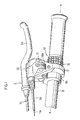
- Figure 1 is an oblique view of a particular embodiment of a twist-grip shift control device 10 according to the present invention mounted together with a brake lever assembly 9.
- shift control device 10 includes a housing 12 mounted around a handlebar 8, a rotatable handgrip 16 structured for rotation around an axis X coaxial with handlebar 8, a pulley 21 for pulling and releasing an inner wire 11a of control cable 11, and a pulley retaining member 28 for retaining pulley 21 to housing 12.
- Pulley retaining member 28 may include a framed opening 28a for selectively displaying a numeral disposed on pulley 21 indicating the currently selected gear.
- a motion transmitting mechanism (not shown) is disposed between rotatable handgrip 16 and pulley 21 for transmitting rotation of handgrip 16 to pulley 21.
- the motion transmitting mechanism may be constructed, for example, according to copending U.S. patent application number 08/854,520 filed May 12, 1997 entitled “Bicycle Shift Control Device” by Takuro Yamane and incorporated herein by reference. Since the motion transmitting mechanism does not form a part of the present invention, a detailed description of that mechanism shall be omitted.
- Brake lever assembly 9 includes a brake lever 9a pivotably mounted to a brake lever bracket 9b which, in turn, is mounted around handlebar 8 in close proximity to (e.g., adjacent) housing 12 of shift control device 10. Brake lever 9a is connected to a brake control cable 9c for controlling a brake device in a conventional manner.
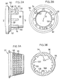
- handgrip 16 includes a rotatable member 50 and a flexible grip 54.
- rotatable member 50 includes a generally cylindrical main body 56 having an outer peripheral surface 58; a generally frustoconical intermediate portion 62, and a larger generally cylindrical portion 66 which interfaces with the motion transmitting mechanism within housing 12.
- a plurality of grip engaging members in the form of ribs 70 elongated in the direction of the handlebar axis X extend radially outwardly from outer peripheral surface 58 of main body 56.
- ribs 70 are evenly spaced in the circumferential direction of outer peripheral surface 58.
- Each rib includes a pair of side surfaces 74 that extend from a side surface 82 of frustoconical portion 62 in the direction of the handlebar axis X, and a top surface 86 that inclines slightly radially inwardly from side surface 82 of frustoconical portion 62 to a rib end surface 90 located at an intermediate portion of outer peripheral surface 58.
- the plurality of ribs 70 define a corresponding plurality of valleys 94 disposed between each pair of adjacent ribs 70, where the bottom floor 92 of each valley 94 is formed by outer peripheral surface 58 of main body 56.
- outer peripheral surface 58 has a constant radius of curvature R from handlebar axis X along its entire axial length so that outer peripheral surface 58 has the shape of a straight cylinder.
- the floor 92 of each valley 94 likewise has a constant radius of curvature as shown in Figure 2B.
- flexible grip 54 snugly fits around outer peripheral surface 58 of rotatable member 50, and an outer peripheral surface 96 of grip 54 includes a plurality of gripping projections 98 to further facilitate traction between the rider's hand and grip 54 (and hence ) rotatable handgrip 16.
- the inner peripheral surface 100 of grip 54 includes a plurality of rotatable member engaging recesses 104 that are evenly spaced in the circumferential direction of inner peripheral surface 100. Each rotatable member engaging recess 104 is shaped for snugly fitting to a corresponding rib 70 so that grip 54 is nonrotatably secured to rotatable member 50.
- a plurality of recesses 108 disposed between spaced apart pairs of inner peripheral surface portions 109 likewise are evenly spaced along the inner peripheral surface of grip 54.
- Each recesses 108 cooperates with a corresponding valley floor 92 for forming a plurality of spaces 110 as shown in Figure 4.
- Inner peripheral surface portions 109 are disposed adjacent to their corresponding ribs 70 and contact both the rib 70 and the adjacent valley floor 92 to snugly fit grip 54 to rotatable member 50.
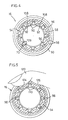
- Figure 5 is a side cross sectional view of the rotatable member 50 and flexible grip 54 illustrating how the flexible grip 54 bends in response to a gripping force exerted by a hand.
- a finger 120 presses radially inwardly to firmly grasp rotatable grip 16.
- the portions of grip 54 disposed over spaces 110 form dents 124 and 126 which conform to finger 120 in response to the radially inwardly directed pressure of finger 120.
- the portions of grip 54 disposed over spaces 110 bend radially inwardly as shown in Figure 5 for partially or substantially reducing the volume of the corresponding space 110.
- dents 124 and 126 enhance the traction between the rider's hand and rotatable handgrip 16 by conforming more closely to the rider's hand. Also, there are no sharp edges jamming into the rider's hand as in the prior art rib/nub designs. Furthermore, the yielding nature of grip 54 also cushions the rider's hand to avoid the excessive pressures caused by prior art rib/nub designs, thus further reducing the risk of pain or fatigue.
- Figure 6 is a side cross sectional view of an alternative embodiment of a rotatable handgrip 16A according to the present invention using a different rotatable member 50A and flexible grip 54A.
- grip 54A includes a plurality of rotatable member engaging members 55A projecting radially inwardly from the inner peripheral surface 100A.
- Rotatable member 50A includes a plurality of grip engaging recesses 57A formed in outer peripheral surface 58A, wherein each rotatable member engaging member 55A is disposed in a corresponding grip engaging recess 57A.
- a plurality of recesses 108A disposed between adjacent pairs of rotatable member engaging members 55A are evenly spaced along the inner peripheral surface 100A of grip 54A.
- Each recess 108A cooperates with a corresponding portion of the outer peripheral surface 58A of rotatable member 50A for forming a plurality of spaces 110A that function in the same manner as spaces 110 in the first embodiment.
- Figure 7 is a side cross sectional view of another alternative embodiment of a rotatable handgrip 16B according to the present invention using a different rotatable member 50B and flexible grip 54B.
- the rotatable member 50B includes a plurality of grip engaging members in the form of ribs 70B projecting radially outwardly from the outer peripheral surface 58B
- the grip 54B includes a corresponding plurality of rotatable member engaging recess 104B
- each grip engaging member 70B is disposed in a corresponding rotatable member engaging recess 104B.
- grip 54B does not have recesses corresponding to recesses 108 in the first embodiment.
- a plurality of evenly spaced recesses 150 are formed in the outer peripheral surface 58B of rotatable member 50B. Each recess 150 cooperates with the inner peripheral surface 100B of grip 54B for forming a plurality of spaces 110B that function in the same manner as spaces 110 in the first embodiment.
- Figure 8 is a side cross sectional view of another alternative embodiment of a rotatable handgrip 16C according to the present invention using a different rotatable member 50C and flexible grip 54C.
- the grip 54C includes a plurality of rotatable member engaging members 55C projecting radially inwardly from the inner peripheral surface 100C
- the rotatable member 50C includes a plurality of grip engaging recesses 57C formed in the outer peripheral surface 58C
- each rotatable member engaging member 55C is disposed in a corresponding grip engaging recess 57C.
- a plurality of evenly spaced recesses 150C are formed in the outer peripheral surface 58C of rotatable member 50C.
- Each recess 150C cooperates with the inner peripheral surface 100C of grip 54C for forming a plurality of spaces 110C that function in the same manner as spaces 110 in the first embodiment.
Description
- The present invention is directed to bicycle control devices and, more particularly, to a grip for a twist-grip shift control device which conforms more closely to a rider's hand.
- Twist-grip shift control devices are sometimes used to control various types of bicycle transmissions. Examples of such devices are disclosed in JP 44-26571; USP 3,633437; USP 4,900,291 and USP 5,197,927. Also from EP 0 759 393 Al a speed change operating device for a bicycle is known to operate a front or a rear derailleur of a bicycle. Such devices typically include a generally annular rotatable member that is mounted around the bicycle handlebar coaxially with the handlebar axis, wherein rotation of the rotatable member with the palm of the hand controls the pulling and releasing of the transmission control cable.
- The US 3,344,684 provides a plastic grip for the handlebar of a bicycle, of a motorcycle or the like which is formed by an inner shell and an outer shell which are spaced from each other to provide a body which flexes inwardly when grasped to provide a dampening effect while riding the bicycle.
- For reliable operation of twist-grip shift control devices, it is desirable to have adequate traction between the palm of the hand and the rotatable member. USP 5,564,316 and USP 5,584,213 discuss the use of nubs and elongated ribs on a flexible cover to increase the traction between the hand and the rotatable member. However, while such nubs and ribs may help improve traction, they also tend to jam into the rider's hand, thus creating pain and fatigue.
- The present invention is directed to a rotatable member for a twist-grip shift control device wherein the grip portion of the rotatable member conforms closely to a rider's hand to increase traction between the palm of the hand and the rotatable member, but which significantly decreases the risk of pain and fatigue. In one embodiment of the present invention, a rotatable handgrip for a twist-grip shift control device includes a rotatable member and a flexible grip disposed over the rotatable member. One or more spaces are defined between an inner peripheral surface of the grip and an outer peripheral surface of the rotatable member so that the grip bends radially inwardly in response to pressure from a hand part (palm, finger, thumb, etc.) so as to generally conform to the hand part. The space may be formed by a recess formed on the inner peripheral surface of the grip, on the outer peripheral surface of the rotatable member, a combination of recesses on the grip and the rotatable member, or through some other means. A rotatable grip constructed according to the present invention increases traction between the palm of the hand and the rotatable grip without requiring ribs or nubs. However, the present invention also may be employed advantageously in a handgrip which uses ribs and nubs, because the space between the grip and the rotatable member allow the ribs and nubs to yield to the pressure of the rider's hand. This, in turn, reduces or eliminates the incidences of pain and fatigue.
-
- Figure 1 is an oblique view of a particular embodiment of a bicycle twist-grip shift control device according to the present invention mounted together with a brake lever assembly;
- Figures 2A and 2B are front and side views, respectively, of a particular embodiment of a rotatable member according to the present invention used in the twist-grip shift control device of Figure 1;
- Figures 3A and 3B are front and side views, respectively, of a particular embodiment of a flexible grip according to the present invention that is used with the rotatable member shown in Figures 2A and 2B;
- Figure 4 is a side cross sectional view illustrating the flexible grip shown in Figures 3A and 3B installed on the rotatable member shown in Figures 2A and 2B;
- Figure 5 is a side cross sectional view of the rotatable member and flexible grip illustrating how the flexible grip bends in response to a gripping force exerted by a hand;
- Figure 6 is a side cross sectional view of an alternative embodiment of a rotatable member and flexible grip according to the present invention;
- Figure 7 is a side cross sectional view of another alternative embodiment of a rotatable member and flexible grip according to the present invention; and
- Figure 8 is a side cross sectional view of another alternative embodiment of a rotatable member and flexible grip according to the present invention.
-
- Figure 1 is an oblique view of a particular embodiment of a twist-grip
shift control device 10 according to the present invention mounted together with abrake lever assembly 9. As shown in Figure 1,shift control device 10 includes ahousing 12 mounted around ahandlebar 8, arotatable handgrip 16 structured for rotation around an axis X coaxial withhandlebar 8, apulley 21 for pulling and releasing aninner wire 11a of control cable 11, and apulley retaining member 28 for retainingpulley 21 tohousing 12. Pulley retainingmember 28 may include a framedopening 28a for selectively displaying a numeral disposed onpulley 21 indicating the currently selected gear. A motion transmitting mechanism (not shown) is disposed betweenrotatable handgrip 16 andpulley 21 for transmitting rotation ofhandgrip 16 topulley 21. The motion transmitting mechanism may be constructed, for example, according to copending U.S. patent application number 08/854,520 filed May 12, 1997 entitled "Bicycle Shift Control Device" by Takuro Yamane and incorporated herein by reference. Since the motion transmitting mechanism does not form a part of the present invention, a detailed description of that mechanism shall be omitted. -
Brake lever assembly 9 includes abrake lever 9a pivotably mounted to abrake lever bracket 9b which, in turn, is mounted aroundhandlebar 8 in close proximity to (e.g., adjacent)housing 12 ofshift control device 10. Brakelever 9a is connected to abrake control cable 9c for controlling a brake device in a conventional manner. - As shown in Figures 2A, 2B, 3A, 3B and 4,
handgrip 16 includes arotatable member 50 and aflexible grip 54. As shown in Figures 2A and 2B,rotatable member 50 includes a generally cylindricalmain body 56 having an outerperipheral surface 58; a generally frustoconicalintermediate portion 62, and a larger generallycylindrical portion 66 which interfaces with the motion transmitting mechanism withinhousing 12. A plurality of grip engaging members in the form ofribs 70 elongated in the direction of the handlebar axis X extend radially outwardly from outerperipheral surface 58 ofmain body 56. In this embodiment,ribs 70 are evenly spaced in the circumferential direction of outerperipheral surface 58. Each rib includes a pair ofside surfaces 74 that extend from aside surface 82 offrustoconical portion 62 in the direction of the handlebar axis X, and atop surface 86 that inclines slightly radially inwardly fromside surface 82 offrustoconical portion 62 to arib end surface 90 located at an intermediate portion of outerperipheral surface 58. The plurality ofribs 70 define a corresponding plurality ofvalleys 94 disposed between each pair ofadjacent ribs 70, where thebottom floor 92 of eachvalley 94 is formed by outerperipheral surface 58 ofmain body 56. In this embodiment, outerperipheral surface 58 has a constant radius of curvature R from handlebar axis X along its entire axial length so that outerperipheral surface 58 has the shape of a straight cylinder. As a result, thefloor 92 of eachvalley 94 likewise has a constant radius of curvature as shown in Figure 2B. - As shown in Figures 3A, 3B, and 4,
flexible grip 54 snugly fits around outerperipheral surface 58 ofrotatable member 50, and an outerperipheral surface 96 ofgrip 54 includes a plurality ofgripping projections 98 to further facilitate traction between the rider's hand and grip 54 (and hence )rotatable handgrip 16. The innerperipheral surface 100 ofgrip 54 includes a plurality of rotatablemember engaging recesses 104 that are evenly spaced in the circumferential direction of innerperipheral surface 100. Each rotatablemember engaging recess 104 is shaped for snugly fitting to acorresponding rib 70 so thatgrip 54 is nonrotatably secured torotatable member 50. A plurality ofrecesses 108 disposed between spaced apart pairs of innerperipheral surface portions 109 likewise are evenly spaced along the inner peripheral surface ofgrip 54. Eachrecesses 108 cooperates with acorresponding valley floor 92 for forming a plurality ofspaces 110 as shown in Figure 4. Innerperipheral surface portions 109 are disposed adjacent to theircorresponding ribs 70 and contact both therib 70 and theadjacent valley floor 92 to snugly fitgrip 54 torotatable member 50. - Figure 5 is a side cross sectional view of the
rotatable member 50 andflexible grip 54 illustrating how theflexible grip 54 bends in response to a gripping force exerted by a hand. As shown in Figure 5, afinger 120 presses radially inwardly to firmly grasprotatable grip 16. Because of the flexibility ofgrip 54, the portions ofgrip 54 disposed overspaces 110form dents finger 120 in response to the radially inwardly directed pressure offinger 120. When.further pressure is applied byfinger 120, the portions ofgrip 54 disposed overspaces 110 bend radially inwardly as shown in Figure 5 for partially or substantially reducing the volume of thecorresponding space 110. Because of this yielding nature ofgrip 54,dents rotatable handgrip 16 by conforming more closely to the rider's hand. Also, there are no sharp edges jamming into the rider's hand as in the prior art rib/nub designs. Furthermore, the yielding nature ofgrip 54 also cushions the rider's hand to avoid the excessive pressures caused by prior art rib/nub designs, thus further reducing the risk of pain or fatigue. - Figure 6 is a side cross sectional view of an alternative embodiment of a
rotatable handgrip 16A according to the present invention using a differentrotatable member 50A andflexible grip 54A. In this embodiment,grip 54A includes a plurality of rotatablemember engaging members 55A projecting radially inwardly from the innerperipheral surface 100A.Rotatable member 50A includes a plurality ofgrip engaging recesses 57A formed in outerperipheral surface 58A, wherein each rotatablemember engaging member 55A is disposed in a corresponding gripengaging recess 57A. A plurality ofrecesses 108A disposed between adjacent pairs of rotatablemember engaging members 55A are evenly spaced along the innerperipheral surface 100A ofgrip 54A. Eachrecess 108A cooperates with a corresponding portion of the outerperipheral surface 58A ofrotatable member 50A for forming a plurality ofspaces 110A that function in the same manner asspaces 110 in the first embodiment. - Figure 7 is a side cross sectional view of another alternative embodiment of a
rotatable handgrip 16B according to the present invention using a differentrotatable member 50B andflexible grip 54B. As in the first embodiment, therotatable member 50B includes a plurality of grip engaging members in the form of ribs 70B projecting radially outwardly from the outerperipheral surface 58B, thegrip 54B includes a corresponding plurality of rotatablemember engaging recess 104B, and each grip engaging member 70B is disposed in a corresponding rotatablemember engaging recess 104B. However, in this embodiment,grip 54B does not have recesses corresponding torecesses 108 in the first embodiment. Instead, a plurality of evenly spacedrecesses 150 are formed in the outerperipheral surface 58B ofrotatable member 50B. Eachrecess 150 cooperates with the innerperipheral surface 100B ofgrip 54B for forming a plurality of spaces 110B that function in the same manner asspaces 110 in the first embodiment. - Figure 8 is a side cross sectional view of another alternative embodiment of a
rotatable handgrip 16C according to the present invention using a differentrotatable member 50C andflexible grip 54C. In this embodiment, thegrip 54C includes a plurality of rotatablemember engaging members 55C projecting radially inwardly from the innerperipheral surface 100C, therotatable member 50C includes a plurality ofgrip engaging recesses 57C formed in the outerperipheral surface 58C, and each rotatablemember engaging member 55C is disposed in a correspondinggrip engaging recess 57C. A plurality of evenly spaced recesses 150C are formed in the outerperipheral surface 58C ofrotatable member 50C. Eachrecess 150C cooperates with the innerperipheral surface 100C ofgrip 54C for forming a plurality ofspaces 110C that function in the same manner asspaces 110 in the first embodiment. - While the above is a description of various embodiments of the present invention, further modifications may be employed without departing from the spirit and scope of the present invention. For example, the size, orientation, location and shape of the various components may be changed as desired. Material may be added or removed from the parts as well. Thus, the scope of the invention should not be limited by the specific structures disclosed. Instead, the true scope of the invention should be determined by the following claims. Of course, although labeling symbols are used in the claims in order to facilitate reference to the figures, the present invention is not intended to be limited to the constructions in the appended figures by such labeling.
Claims (26)
- A rotatable handgrip (16, 16A) for a bicycle shifter comprising:characterized in that a space (110, 110A) is defined between an inner peripheral surface of the grip (54, 54A) and an outer peripheral surface of the rotatable member (50, 50A) so that the grip (54, 54A) dents radially inwardly in response to pressure from a hand part so as to generally conform to the hand part; and wherein a recess (108, 108A) is formed on the inner peripheral surface of the grip (54, 54A) for forming the space (110, 110A).a rotatable member (50, 50A), anda flexible grip (54, 54A) disposed over the rotatable member (50, 50A),
- A rotatable handgrip (16B, 16C) for a bicycle shifter comprising:characterized in that a space (110B, 110C) is defined between an inner peripheral surface of the grip (54B, 54C) and an outer peripheral surface of the rotatable member (50B, 50C) so that the grip (54B, 54C) dents radially inwardly in response to pressure from a hand part so as to generally conform to the hand part; and wherein a recess (150) is formed on the outer peripheral surface of the rotatable member for forming the space (110B, 110C).a rotatable member (50B, 50C), anda flexible grip (54B, 54C) disposed over the rotatable member (50B, 50C),
- The handgrip according to claim 1 or 2, characterized in that the grip (54, 54A, 54B, 54C) bends radially inwardly into the space (110, 110A, 110B, 110C)in response to pressure from the hand part.
- The handgrip according to claim 1 or 3, characterized in that a plurality of the recesses (108, 108A) are formed on the inner peripheral surface of the grip (54, 54A) for forming a plurality of the spaces.
- The handgrip according to claim 4, characterized in that the plurality of recesses (108, 108A) are disposed evenly along the inner peripheral surface of the grip (54, 54A).
- The handgrip according to any of claims 1 to 5, characterized in that the rotatable member (50) includes a grip engaging member projecting radially outwardly from the outer peripheral surface, wherein the grip includes a rotatable member engaging recess, and wherein the grip engaging member is disposed in the rotatable member engaging recess.
- The handgrip according to any of claims 1 to 5, characterized in that the grip includes a rotatable member engaging member projecting radially inwardly from the inner peripheral surface, wherein the rotatable member includes a grip engaging recess, and wherein the rotatable member engaging member is disposed in the grip engaging recess.
- The handgrip according to any of claims 1 to 5, characterized in that the rotatable member includes a plurality of elongated ribs projecting radially outwardly from the outer peripheral surface, wherein the grip includes a plurality of rotatable member engaging recesses, and wherein the plurality of ribs are disposed in corresponding ones of the plurality of rotatable member engaging recesses.
- The handgrip according to claim 8, characterized in that a plurality of the recesses are formed on the inner peripheral surface of the grip for forming a plurality of the spaces.
- The handgrip according to claim 9, characterized in that the plurality of ribs are disposed evenly in a circumferential direction along the outer peripheral surface of the rotatable member.
- The handgrip according to claim 10, characterized in that the plurality of recesses are disposed evenly in the circumferential direction along the inner peripheral surface of the grip.
- The handgrip according to claim 11, characterized in that a single recess is disposed between each adjacent pair of the plurality of ribs.
- The handgrip according to claim 1 or 2, characterized in that the grip includes a plurality of elongated ribs projecting radially inwardly from the inner peripheral surface, wherein the rotatable member includes a plurality of grip engaging recesses, and wherein the plurality of ribs are disposed in corresponding ones of the plurality of grip engaging recesses.
- The handgrip according to claim 13, characterized in that a plurality of the recesses are formed on the inner peripheral surface of the grip for forming a plurality of the spaces.
- The handgrip according to claim 14, characterized in that the plurality of ribs are disposed evenly in a circumferential direction along the inner peripheral surface of the grip.
- The handgrip according to claim 15, characterized in that the plurality of recesses are disposed evenly in the circumferential direction along the inner peripheral surface of the grip.
- The handgrip according to claim 2, characterized in that a plurality of the recesses are formed on the outer peripheral surface of the rotatable member (50B, 50C) for forming a plurality of the spaces.
- The handgrip according to claim 17, characterized in that the plurality of recesses are disposed evenly along the outer peripheral surface of the rotatable member.
- The handgrip according to claim 8, characterized in that a plurality of the recesses are formed on the outer peripheral surface of the rotatable member for forming a plurality of the spaces.
- The handgrip according to claim 19, characterized in that the plurality of ribs are disposed evenly in a circumferential direction along the outer peripheral surface of the rotatable member.
- The handgrip according to claim 20, characterized in that the plurality of recesses are disposed evenly in a circumferential direction along the outer peripheral surface of the rotatable member.
- The handgrip according to claim 21, characterized in that a single recess is disposed between each adjacent pair of the plurality of ribs.
- The handgrip according to claim 13, characterized in that a plurality of the recesses are formed on the outer peripheral surface of the rotatable member for forming a plurality of the spaces.
- The handgrip according to claim 23, characterized in that the plurality of ribs are disposed evenly in a circumferential direction along the inner peripheral surface of the grip.
- The handgrip according to claim 24, characterized in that the plurality of recesses are disposed evenly in the circumferential direction along the outer peripheral surface of the rotatable member.
- The handgrip according to claim 15 or 25, characterized in that a single recess is disposed between each adjacent pair of the plurality of ribs.
Applications Claiming Priority (2)
| Application Number | Priority Date | Filing Date | Title |
|---|---|---|---|
| US08/900,935 US6101895A (en) | 1997-07-25 | 1997-07-25 | Grip for a bicycle shift control device |
| US900935 | 1997-07-25 |
Publications (4)
| Publication Number | Publication Date |
|---|---|
| EP0893335A2 EP0893335A2 (en) | 1999-01-27 |
| EP0893335A3 EP0893335A3 (en) | 2000-07-19 |
| EP0893335B1 true EP0893335B1 (en) | 2004-04-14 |
| EP0893335B2 EP0893335B2 (en) | 2009-03-25 |
Family
ID=25413321
Family Applications (1)
| Application Number | Title | Priority Date | Filing Date |
|---|---|---|---|
| EP98113714A Expired - Lifetime EP0893335B2 (en) | 1997-07-25 | 1998-07-22 | Grip for a bicycle shift control device |
Country Status (6)
| Country | Link |
|---|---|
| US (4) | US6101895A (en) |
| EP (1) | EP0893335B2 (en) |
| JP (1) | JP2915404B2 (en) |
| CN (1) | CN1090128C (en) |
| DE (1) | DE69823105T3 (en) |
| TW (1) | TW422797B (en) |
Families Citing this family (61)
| Publication number | Priority date | Publication date | Assignee | Title |
|---|---|---|---|---|
| US6389929B1 (en) * | 1999-05-20 | 2002-05-21 | Sram Corporation | Elongated rotatable handgrip |
| DE10025883A1 (en) * | 2000-05-25 | 2001-11-29 | Sram De Gmbh | Integrated twist grip switch |
| US6561058B1 (en) * | 2000-11-20 | 2003-05-13 | Richard A. Steinke | Cushioning hand grip |
| JP4537594B2 (en) * | 2001-02-07 | 2010-09-01 | 本田技研工業株式会社 | Brush cutter |
| US7032475B2 (en) * | 2001-06-07 | 2006-04-25 | Shimano Inc. | Hydraulic gear shift mechanism |
| AT411050B (en) * | 2001-12-28 | 2003-09-25 | Hirt Robert | Throttle grip with flexible casing |
| US6718844B2 (en) * | 2002-02-13 | 2004-04-13 | Shimano, Inc. | Twist-grip shift control device for a bicycle |
| US7150205B2 (en) * | 2002-04-04 | 2006-12-19 | Shimano, Inc. | Handgrip shifter for a bicycle |
| US7363685B2 (en) | 2002-10-28 | 2008-04-29 | Black & Decker Inc. | Handle assembly for tool |
| GB0224955D0 (en) | 2002-10-28 | 2002-12-04 | Black & Decker Inc | Handle assembly for tool |
| US7011600B2 (en) | 2003-02-28 | 2006-03-14 | Fallbrook Technologies Inc. | Continuously variable transmission |
| US20040168538A1 (en) * | 2003-02-28 | 2004-09-02 | Shimano, Inc. | Twist grip for operating a bicycle transmission |
| US7325812B2 (en) * | 2003-05-14 | 2008-02-05 | Eastway Fair Company Limited | Grip assembly for clutch cap, front sleeve, rear sleeve and method of making |
| US7770262B2 (en) * | 2003-05-19 | 2010-08-10 | Robert Bosch Tool Corporation | Cushion grip handle |
| US7104154B2 (en) | 2003-05-29 | 2006-09-12 | Shimano Inc. | Bicycle shift control device |
| US7013751B2 (en) * | 2003-05-29 | 2006-03-21 | Shimano Inc. | Bicycle shift control device |
| DE102004014888A1 (en) * | 2004-03-26 | 2005-10-20 | Bayerische Motoren Werke Ag | operating element |
| US7861380B2 (en) * | 2004-05-07 | 2011-01-04 | Tubular Fabricators Industry, Inc. | Replaceable hand grip |
| US20050250605A1 (en) * | 2004-05-07 | 2005-11-10 | Tubular Fabricators Industry, Inc. | Replaceable grip handle |
| MX2007003828A (en) | 2004-10-05 | 2007-04-20 | Fallbrook Technologies Inc | Continuously variable transmission. |
| US7730589B2 (en) | 2005-05-27 | 2010-06-08 | Black & Decker Inc. | Power tool with gel grip including an integral backing |
| US20060272126A1 (en) * | 2005-06-01 | 2006-12-07 | Burgess Andrew A | Spinning handle grip assembly for towable luggage item |
| JP2007076545A (en) * | 2005-09-15 | 2007-03-29 | Shimano Inc | Bicycle speed change device |
| KR101831822B1 (en) | 2005-10-28 | 2018-02-23 | 폴브룩 인텔렉츄얼 프로퍼티 컴퍼니 엘엘씨 | Electromotive drives |
| PL1954959T3 (en) | 2005-11-22 | 2013-10-31 | Fallbrook Ip Co Llc | Continuously variable transmission |
| KR101317329B1 (en) | 2005-12-09 | 2013-10-15 | 폴브룩 테크놀로지즈 인크 | Continuously variable transmission |
| EP1811202A1 (en) | 2005-12-30 | 2007-07-25 | Fallbrook Technologies, Inc. | A continuously variable gear transmission |
| WO2009006481A2 (en) | 2007-07-05 | 2009-01-08 | Fallbrook Technologies Inc. | Continuously variable transmission |
| US20070178793A1 (en) * | 2006-01-27 | 2007-08-02 | Gerello Brian C | Wood panel with water vapor-permeable polyester layer |
| US7882762B2 (en) * | 2006-01-30 | 2011-02-08 | Fallbrook Technologies Inc. | System for manipulating a continuously variable transmission |
| EP2125469A2 (en) | 2007-02-01 | 2009-12-02 | Fallbrook Technologies Inc. | System and methods for control of transmission and/or prime mover |
| CN101657653B (en) | 2007-02-12 | 2014-07-16 | 福博科知识产权有限责任公司 | Continuously variable transmissions and methods therefor |
| TWI461615B (en) | 2007-02-16 | 2014-11-21 | Fallbrook Ip Co Llc | Infinitely variable transmissions, continuously variable transmissions, methods, assemblies, subassemblies, and components therefor |
| EP2573425A3 (en) | 2007-04-24 | 2017-07-26 | Fallbrook Intellectual Property Company LLC | Electric traction drives |
| CN103939602B (en) | 2007-11-16 | 2016-12-07 | 福博科知识产权有限责任公司 | Controller for variable speed drive |
| CA2708634C (en) | 2007-12-21 | 2017-08-01 | Fallbrook Technologies Inc. | Automatic transmissions and methods therefor |
| EP2100805B1 (en) | 2008-03-12 | 2013-08-21 | Campagnolo S.r.l. | Cover sheath for a grippable bicycle component and grippable component equipped with such a sheath |
| WO2009148461A1 (en) | 2008-06-06 | 2009-12-10 | Fallbrook Technologies Inc. | Infinitely variable transmissions, continuously variable transmissions, methods, assemblies, subassemblies, and components therefor |
| CN107246463A (en) | 2008-06-23 | 2017-10-13 | 福博科知识产权有限责任公司 | Buncher |
| CA2732668C (en) | 2008-08-05 | 2017-11-14 | Fallbrook Technologies Inc. | Methods for control of transmission and prime mover |
| US8469856B2 (en) | 2008-08-26 | 2013-06-25 | Fallbrook Intellectual Property Company Llc | Continuously variable transmission |
| US8167759B2 (en) | 2008-10-14 | 2012-05-01 | Fallbrook Technologies Inc. | Continuously variable transmission |
| PL2419658T3 (en) | 2009-04-16 | 2014-02-28 | Fallbrook Ip Co Llc | Stator assembly and shifting mechanism for a continuously variable transmission |
| US20100282870A1 (en) * | 2009-05-07 | 2010-11-11 | Chin-Yuan Chen | Spraying Gun Whose Grip is Positioned Closely |
| US20110088504A1 (en) * | 2009-10-15 | 2011-04-21 | Falcon Cycle Tech. Co., Ltd. | Grip shifter assembly |
| US8512195B2 (en) | 2010-03-03 | 2013-08-20 | Fallbrook Intellectual Property Company Llc | Infinitely variable transmissions, continuously variable transmissions, methods, assemblies, subassemblies, and components therefor |
| US8888643B2 (en) | 2010-11-10 | 2014-11-18 | Fallbrook Intellectual Property Company Llc | Continuously variable transmission |
| US20130134640A1 (en) * | 2011-11-29 | 2013-05-30 | Gina Thaxton | Corner and edge cushioning device, system and method of using same |
| WO2013112408A1 (en) | 2012-01-23 | 2013-08-01 | Fallbrook Intellectual Property Company Llc | Infinitely variable transmissions, continuously variable transmissions methods, assemblies, subassemblies, and components therefor |
| JP6660876B2 (en) | 2013-04-19 | 2020-03-11 | フォールブルック インテレクチュアル プロパティー カンパニー エルエルシー | Continuously variable transmission |
| USD794510S1 (en) | 2014-10-29 | 2017-08-15 | Gogoro Inc. | Motor scooter and/or toy replica thereof |
| USD828310S1 (en) | 2014-11-07 | 2018-09-11 | Gogoro Inc. | Button of vehicle handlebar |
| USD784788S1 (en) * | 2014-11-07 | 2017-04-25 | Gogoro Inc. | Vehicle handlebar lever |
| US10400872B2 (en) | 2015-03-31 | 2019-09-03 | Fallbrook Intellectual Property Company Llc | Balanced split sun assemblies with integrated differential mechanisms, and variators and drive trains including balanced split sun assemblies |
| US10047861B2 (en) | 2016-01-15 | 2018-08-14 | Fallbrook Intellectual Property Company Llc | Systems and methods for controlling rollback in continuously variable transmissions |
| JP7137475B2 (en) | 2016-03-18 | 2022-09-14 | フォールブルック インテレクチュアル プロパティー カンパニー エルエルシー | Continuously variable transmission, system and method |
| US10023266B2 (en) | 2016-05-11 | 2018-07-17 | Fallbrook Intellectual Property Company Llc | Systems and methods for automatic configuration and automatic calibration of continuously variable transmissions and bicycles having continuously variable transmissions |
| US10525315B1 (en) * | 2018-07-20 | 2020-01-07 | Harry Matthew Wells | Grip assembly for sports equipment |
| US11215268B2 (en) | 2018-11-06 | 2022-01-04 | Fallbrook Intellectual Property Company Llc | Continuously variable transmissions, synchronous shifting, twin countershafts and methods for control of same |
| US11174922B2 (en) | 2019-02-26 | 2021-11-16 | Fallbrook Intellectual Property Company Llc | Reversible variable drives and systems and methods for control in forward and reverse directions |
| US10888754B2 (en) * | 2019-05-16 | 2021-01-12 | Harry Matthew Wells | Grip assembly for sports equipment |
Citations (13)
| Publication number | Priority date | Publication date | Assignee | Title |
|---|---|---|---|---|
| US599131A (en) * | 1898-02-15 | Pneumatic grip or handle | ||
| GB465270A (en) * | 1935-11-02 | 1937-05-03 | Denis James O Brien | Improvements in or relating to grips or handles |
| US2222121A (en) * | 1939-08-28 | 1940-11-19 | Benjamin D Leavitt | Handle bar grip |
| US3189069A (en) * | 1963-12-06 | 1965-06-15 | Stanley Works | Tool handle with resilient gripping means |
| US3340914A (en) * | 1965-05-10 | 1967-09-12 | James B Ricks | Ratchet grip |
| US3713350A (en) * | 1971-05-17 | 1973-01-30 | Schwinn Bicycle Co | Air cushion handlebar grip |
| SU592659A1 (en) * | 1975-02-04 | 1978-02-15 | Тульский Машиностроительный Завод Им.В.М.Рябикова | Cycle handle-bar grip |
| US4768406A (en) * | 1986-04-22 | 1988-09-06 | Edwin Fitzwater | Torque compensating apparatus |
| US4969231A (en) * | 1989-05-17 | 1990-11-13 | Easco Hand Tools, Inc. | Hand tool handle having end cap with indicia |
| US4972733A (en) * | 1988-12-12 | 1990-11-27 | Textron Inc | Shock absorbing grip |
| US5193246A (en) * | 1991-07-23 | 1993-03-16 | Huang Ing Chung | Air cushion grip with a cubic supporting structure and shock-absorbing function |
| EP0523257B1 (en) * | 1991-02-13 | 1996-05-08 | Mory Suntour Inc. | Device for making gear change of bicycle |
| US5564316A (en) * | 1994-03-07 | 1996-10-15 | Sram Corporation | Nubbed grip for rotatable bicycle gear shifter |
Family Cites Families (17)
| Publication number | Priority date | Publication date | Assignee | Title |
|---|---|---|---|---|
| US588794A (en) | 1897-08-24 | Handle for tools and bicycle handle-bars | ||
| GB189913291A (en) | 1899-06-27 | 1900-05-05 | George Duckworth Roberts | An Improved Handle for Cycles, Motor Cars, and the like. |
| GB189916576A (en) | 1899-08-15 | 1900-06-16 | Harry Adrian Taylor Stoakes | Improvements in Pneumatic Handles for Velocipedes, Motor-cars, or other similar Purposes. |
| DE675170C (en) | 1936-11-11 | 1939-05-02 | Karl Hagebeuker | Handle with helically wound air hose |
| US3344684A (en) * | 1965-10-05 | 1967-10-03 | Steere Entpr Inc | Grip |
| JPS4426571B1 (en) * | 1965-11-17 | 1969-11-07 | ||
| US3633437A (en) * | 1969-07-31 | 1972-01-11 | Takuo Ishida | Hand control device for speed change gear mechanism of a bicycle |
| FR2403172A1 (en) | 1977-09-14 | 1979-04-13 | Dupuis Pierre | Handle with deforming grip for e.g. tennis racquet - has supple sleeve on shaft and forming volumes contg. small hard balls |
| JPS55142143A (en) * | 1979-04-20 | 1980-11-06 | Japanese National Railways<Jnr> | Anti-vibration grip |
| JPS55142142A (en) * | 1979-04-20 | 1980-11-06 | Japanese National Railways<Jnr> | Anti-vibration grip |
| DE3343015A1 (en) | 1982-11-29 | 1984-05-30 | Shimano Industrial Co., Ltd., Sakai, Osaka | BICYCLE PEDAL |
| US4900291B1 (en) * | 1988-01-06 | 2000-04-25 | Sram Corp | Bicycle gear shifting method and apparatus |
| FR2629724A1 (en) | 1988-04-12 | 1989-10-13 | Buand Thierry | RAQUETTE HANDLE, IN PARTICULAR FOR SPORTS USE, PREFERABLY ANTI SUDATION AND ANTI VIBRATION |
| US5197927B1 (en) * | 1991-03-20 | 2000-10-17 | Sram Corp | Bicycle derailleur cable actuating system |
| US5355552A (en) * | 1991-07-23 | 1994-10-18 | Huang Ing Chung | Air cushion grip with a cubic supporting structure and shock-absorbing function |
| US5476019A (en) * | 1994-03-07 | 1995-12-19 | Sram Corporation | Rotatable handgrip actuating system |
| DE69623086T2 (en) * | 1995-03-13 | 2003-05-08 | Sakae Co Ltd | CONTROL DEVICE FOR A BICYCLE GEAR |
-
1997
- 1997-07-25 US US08/900,935 patent/US6101895A/en not_active Expired - Fee Related
-
1998
- 1998-07-14 TW TW087111441A patent/TW422797B/en not_active IP Right Cessation
- 1998-07-22 DE DE69823105T patent/DE69823105T3/en not_active Expired - Fee Related
- 1998-07-22 EP EP98113714A patent/EP0893335B2/en not_active Expired - Lifetime
- 1998-07-24 CN CN98116390A patent/CN1090128C/en not_active Expired - Fee Related
- 1998-07-27 JP JP10210630A patent/JP2915404B2/en not_active Expired - Fee Related
-
2000
- 2000-06-21 US US09/599,291 patent/US6212972B1/en not_active Expired - Fee Related
- 2000-06-21 US US09/599,970 patent/US6276231B1/en not_active Expired - Fee Related
- 2000-06-21 US US09/599,805 patent/US6227069B1/en not_active Expired - Fee Related
Patent Citations (13)
| Publication number | Priority date | Publication date | Assignee | Title |
|---|---|---|---|---|
| US599131A (en) * | 1898-02-15 | Pneumatic grip or handle | ||
| GB465270A (en) * | 1935-11-02 | 1937-05-03 | Denis James O Brien | Improvements in or relating to grips or handles |
| US2222121A (en) * | 1939-08-28 | 1940-11-19 | Benjamin D Leavitt | Handle bar grip |
| US3189069A (en) * | 1963-12-06 | 1965-06-15 | Stanley Works | Tool handle with resilient gripping means |
| US3340914A (en) * | 1965-05-10 | 1967-09-12 | James B Ricks | Ratchet grip |
| US3713350A (en) * | 1971-05-17 | 1973-01-30 | Schwinn Bicycle Co | Air cushion handlebar grip |
| SU592659A1 (en) * | 1975-02-04 | 1978-02-15 | Тульский Машиностроительный Завод Им.В.М.Рябикова | Cycle handle-bar grip |
| US4768406A (en) * | 1986-04-22 | 1988-09-06 | Edwin Fitzwater | Torque compensating apparatus |
| US4972733A (en) * | 1988-12-12 | 1990-11-27 | Textron Inc | Shock absorbing grip |
| US4969231A (en) * | 1989-05-17 | 1990-11-13 | Easco Hand Tools, Inc. | Hand tool handle having end cap with indicia |
| EP0523257B1 (en) * | 1991-02-13 | 1996-05-08 | Mory Suntour Inc. | Device for making gear change of bicycle |
| US5193246A (en) * | 1991-07-23 | 1993-03-16 | Huang Ing Chung | Air cushion grip with a cubic supporting structure and shock-absorbing function |
| US5564316A (en) * | 1994-03-07 | 1996-10-15 | Sram Corporation | Nubbed grip for rotatable bicycle gear shifter |
Also Published As
| Publication number | Publication date |
|---|---|
| EP0893335B2 (en) | 2009-03-25 |
| JP2915404B2 (en) | 1999-07-05 |
| DE69823105D1 (en) | 2004-05-19 |
| CN1206669A (en) | 1999-02-03 |
| CN1090128C (en) | 2002-09-04 |
| TW422797B (en) | 2001-02-21 |
| US6212972B1 (en) | 2001-04-10 |
| DE69823105T3 (en) | 2009-08-27 |
| DE69823105T2 (en) | 2004-08-26 |
| US6276231B1 (en) | 2001-08-21 |
| EP0893335A2 (en) | 1999-01-27 |
| JPH1191679A (en) | 1999-04-06 |
| EP0893335A3 (en) | 2000-07-19 |
| US6227069B1 (en) | 2001-05-08 |
| US6101895A (en) | 2000-08-15 |
Similar Documents
| Publication | Publication Date | Title |
|---|---|---|
| EP0893335B1 (en) | Grip for a bicycle shift control device | |
| US5584213A (en) | Rotatable grip for derailleur type bicycle gear shifting system | |
| JP6695126B2 (en) | Manual controls for bicycles, especially hydraulic brakes and gearshifts | |
| EP0352732B1 (en) | Handlebar-mounted gear change lever | |
| EP0047637B1 (en) | Cycle control device | |
| EP0893336B1 (en) | Pulley and bicyle shift control device comprising such a pulley | |
| EP1739000B1 (en) | Control device for a bicycle derailleur | |
| US6957597B2 (en) | Adjusting apparatus for a bicycle brake control device | |
| EP0035855B1 (en) | Modified cross-section handlebars for bicycles | |
| EP1134155B1 (en) | Cable protection mechanism | |
| JPH0858414A (en) | Grip of manually rotatable type gear shifter for bicycle use | |
| US6199447B1 (en) | Bulbous grip for rotatable bicycle gear shifter | |
| EP0256473B1 (en) | Auxiliary brake control assembly for bicycle | |
| EP0671315B1 (en) | Nubbed grip for rotatable bicycle gear shifter | |
| EP1698551A2 (en) | Bicycle control apparatus | |
| EP1452433B1 (en) | Twist grip for operating a bicycle transmission | |
| US20080284126A1 (en) | Adaptive brake and shift mechanism for a bicycle | |
| SU1119908A1 (en) | Device for controlling bycycle brake | |
| EP1189801B1 (en) | A handle device for bicycle, moped, rollator or similar vehicle | |
| EP0792794B1 (en) | Uniaxial bicycle control unit |
Legal Events
| Date | Code | Title | Description |
|---|---|---|---|
| PUAI | Public reference made under article 153(3) epc to a published international application that has entered the european phase |
Free format text: ORIGINAL CODE: 0009012 |
|
| AK | Designated contracting states |
Kind code of ref document: A2 Designated state(s): DE FR GB IE IT |
|
| AX | Request for extension of the european patent |
Free format text: AL;LT;LV;MK;RO;SI |
|
| PUAL | Search report despatched |
Free format text: ORIGINAL CODE: 0009013 |
|
| AK | Designated contracting states |
Kind code of ref document: A3 Designated state(s): AT BE CH CY DE DK ES FI FR GB GR IE IT LI LU MC NL PT SE |
|
| AX | Request for extension of the european patent |
Free format text: AL;LT;LV;MK;RO;SI |
|
| 17P | Request for examination filed |
Effective date: 20000816 |
|
| AKX | Designation fees paid |
Free format text: DE FR GB IE IT |
|
| TPAD | Observations filed by third parties |
Free format text: ORIGINAL CODE: EPIDOS TIPA |
|
| 17Q | First examination report despatched |
Effective date: 20030204 |
|
| GRAP | Despatch of communication of intention to grant a patent |
Free format text: ORIGINAL CODE: EPIDOSNIGR1 |
|
| GRAS | Grant fee paid |
Free format text: ORIGINAL CODE: EPIDOSNIGR3 |
|
| GRAA | (expected) grant |
Free format text: ORIGINAL CODE: 0009210 |
|
| AK | Designated contracting states |
Kind code of ref document: B1 Designated state(s): DE FR GB IE IT |
|
| REG | Reference to a national code |
Ref country code: GB Ref legal event code: FG4D |
|
| REF | Corresponds to: |
Ref document number: 69823105 Country of ref document: DE Date of ref document: 20040519 Kind code of ref document: P |
|
| REG | Reference to a national code |
Ref country code: IE Ref legal event code: FG4D |
|
| ET | Fr: translation filed | ||
| PLBI | Opposition filed |
Free format text: ORIGINAL CODE: 0009260 |
|
| PLAX | Notice of opposition and request to file observation + time limit sent |
Free format text: ORIGINAL CODE: EPIDOSNOBS2 |
|
| 26 | Opposition filed |
Opponent name: SRAM DEUTSCHLAND GMBH Effective date: 20050113 |
|
| PLBB | Reply of patent proprietor to notice(s) of opposition received |
Free format text: ORIGINAL CODE: EPIDOSNOBS3 |
|
| PGFP | Annual fee paid to national office [announced via postgrant information from national office to epo] |
Ref country code: FR Payment date: 20050708 Year of fee payment: 8 |
|
| PGFP | Annual fee paid to national office [announced via postgrant information from national office to epo] |
Ref country code: IE Payment date: 20050713 Year of fee payment: 8 |
|
| PGFP | Annual fee paid to national office [announced via postgrant information from national office to epo] |
Ref country code: GB Payment date: 20050720 Year of fee payment: 8 |
|
| PG25 | Lapsed in a contracting state [announced via postgrant information from national office to epo] |
Ref country code: GB Free format text: LAPSE BECAUSE OF NON-PAYMENT OF DUE FEES Effective date: 20060722 |
|
| PG25 | Lapsed in a contracting state [announced via postgrant information from national office to epo] |
Ref country code: IE Free format text: LAPSE BECAUSE OF NON-PAYMENT OF DUE FEES Effective date: 20060724 |
|
| RAP2 | Party data changed (patent owner data changed or rights of a patent transferred) |
Owner name: SHIMANO INC. |
|
| GBPC | Gb: european patent ceased through non-payment of renewal fee |
Effective date: 20060722 |
|
| REG | Reference to a national code |
Ref country code: IE Ref legal event code: MM4A |
|
| REG | Reference to a national code |
Ref country code: FR Ref legal event code: ST Effective date: 20070330 |
|
| PG25 | Lapsed in a contracting state [announced via postgrant information from national office to epo] |
Ref country code: FR Free format text: LAPSE BECAUSE OF NON-PAYMENT OF DUE FEES Effective date: 20060731 |
|
| PUAH | Patent maintained in amended form |
Free format text: ORIGINAL CODE: 0009272 |
|
| STAA | Information on the status of an ep patent application or granted ep patent |
Free format text: STATUS: PATENT MAINTAINED AS AMENDED |
|
| 27A | Patent maintained in amended form |
Effective date: 20090325 |
|
| AK | Designated contracting states |
Kind code of ref document: B2 Designated state(s): DE FR GB IE IT |
|
| PGFP | Annual fee paid to national office [announced via postgrant information from national office to epo] |
Ref country code: DE Payment date: 20090716 Year of fee payment: 12 |
|
| PGFP | Annual fee paid to national office [announced via postgrant information from national office to epo] |
Ref country code: IT Payment date: 20090717 Year of fee payment: 12 |
|
| PG25 | Lapsed in a contracting state [announced via postgrant information from national office to epo] |
Ref country code: DE Free format text: LAPSE BECAUSE OF NON-PAYMENT OF DUE FEES Effective date: 20110201 |
|
| REG | Reference to a national code |
Ref country code: DE Ref legal event code: R119 Ref document number: 69823105 Country of ref document: DE Effective date: 20110201 |
|
| PG25 | Lapsed in a contracting state [announced via postgrant information from national office to epo] |
Ref country code: IT Free format text: LAPSE BECAUSE OF NON-PAYMENT OF DUE FEES Effective date: 20100722 |