EP0885876B1 - Swallow-tail-shaped liquid crystal compound - Google Patents
Swallow-tail-shaped liquid crystal compound Download PDFInfo
- Publication number
- EP0885876B1 EP0885876B1 EP98111072A EP98111072A EP0885876B1 EP 0885876 B1 EP0885876 B1 EP 0885876B1 EP 98111072 A EP98111072 A EP 98111072A EP 98111072 A EP98111072 A EP 98111072A EP 0885876 B1 EP0885876 B1 EP 0885876B1
- Authority
- EP
- European Patent Office
- Prior art keywords
- liquid crystal
- ferroelectric
- mixture
- crystal compound
- compound
- Prior art date
- Legal status (The legal status is an assumption and is not a legal conclusion. Google has not performed a legal analysis and makes no representation as to the accuracy of the status listed.)
- Expired - Lifetime
Links
- 0 COc1ccc(C(CCC(*c2c(*)c(*)c(**)c(F)c2N=C)C2)C2C2ICCCC2)cc1 Chemical compound COc1ccc(C(CCC(*c2c(*)c(*)c(**)c(F)c2N=C)C2)C2C2ICCCC2)cc1 0.000 description 3
Images
Classifications
-
- C—CHEMISTRY; METALLURGY
- C09—DYES; PAINTS; POLISHES; NATURAL RESINS; ADHESIVES; COMPOSITIONS NOT OTHERWISE PROVIDED FOR; APPLICATIONS OF MATERIALS NOT OTHERWISE PROVIDED FOR
- C09K—MATERIALS FOR MISCELLANEOUS APPLICATIONS, NOT PROVIDED FOR ELSEWHERE
- C09K19/00—Liquid crystal materials
- C09K19/04—Liquid crystal materials characterised by the chemical structure of the liquid crystal components, e.g. by a specific unit
- C09K19/06—Non-steroidal liquid crystal compounds
- C09K19/08—Non-steroidal liquid crystal compounds containing at least two non-condensed rings
- C09K19/10—Non-steroidal liquid crystal compounds containing at least two non-condensed rings containing at least two benzene rings
- C09K19/20—Non-steroidal liquid crystal compounds containing at least two non-condensed rings containing at least two benzene rings linked by a chain containing carbon and oxygen atoms as chain links, e.g. esters or ethers
- C09K19/2007—Non-steroidal liquid crystal compounds containing at least two non-condensed rings containing at least two benzene rings linked by a chain containing carbon and oxygen atoms as chain links, e.g. esters or ethers the chain containing -COO- or -OCO- groups
-
- C—CHEMISTRY; METALLURGY
- C09—DYES; PAINTS; POLISHES; NATURAL RESINS; ADHESIVES; COMPOSITIONS NOT OTHERWISE PROVIDED FOR; APPLICATIONS OF MATERIALS NOT OTHERWISE PROVIDED FOR
- C09K—MATERIALS FOR MISCELLANEOUS APPLICATIONS, NOT PROVIDED FOR ELSEWHERE
- C09K19/00—Liquid crystal materials
- C09K19/02—Liquid crystal materials characterised by optical, electrical or physical properties of the components, in general
- C09K19/0266—Antiferroelectrics
-
- C—CHEMISTRY; METALLURGY
- C07—ORGANIC CHEMISTRY
- C07C—ACYCLIC OR CARBOCYCLIC COMPOUNDS
- C07C69/00—Esters of carboxylic acids; Esters of carbonic or haloformic acids
- C07C69/76—Esters of carboxylic acids having a carboxyl group bound to a carbon atom of a six-membered aromatic ring
- C07C69/94—Esters of carboxylic acids having a carboxyl group bound to a carbon atom of a six-membered aromatic ring of polycyclic hydroxy carboxylic acids, the hydroxy groups and the carboxyl groups of which are bound to carbon atoms of six-membered aromatic rings
-
- C—CHEMISTRY; METALLURGY
- C09—DYES; PAINTS; POLISHES; NATURAL RESINS; ADHESIVES; COMPOSITIONS NOT OTHERWISE PROVIDED FOR; APPLICATIONS OF MATERIALS NOT OTHERWISE PROVIDED FOR
- C09K—MATERIALS FOR MISCELLANEOUS APPLICATIONS, NOT PROVIDED FOR ELSEWHERE
- C09K19/00—Liquid crystal materials
- C09K19/04—Liquid crystal materials characterised by the chemical structure of the liquid crystal components, e.g. by a specific unit
- C09K19/06—Non-steroidal liquid crystal compounds
- C09K19/08—Non-steroidal liquid crystal compounds containing at least two non-condensed rings
- C09K19/10—Non-steroidal liquid crystal compounds containing at least two non-condensed rings containing at least two benzene rings
- C09K19/20—Non-steroidal liquid crystal compounds containing at least two non-condensed rings containing at least two benzene rings linked by a chain containing carbon and oxygen atoms as chain links, e.g. esters or ethers
- C09K19/2007—Non-steroidal liquid crystal compounds containing at least two non-condensed rings containing at least two benzene rings linked by a chain containing carbon and oxygen atoms as chain links, e.g. esters or ethers the chain containing -COO- or -OCO- groups
- C09K2019/2042—Ph-Ph-COO-Ph
Definitions
- the present invention relates to a novel liquid crystal compound having an achiral anti-ferroelectric phase.
- a liquid crystal display device has so far been used mainly to a variety of small-sized display devices on account of its low-voltage operation, low-power consumption and display capability with a thin screen. Further, with the recent application and increased use of a liquid crystal display device to/in the fields of information, office automation-related machines and equipment, and television sets, demands are rapidly increasing for high-performance and large-sized liquid crystal display devices having a larger display capacity and a higher display quality than those of a conventional CRT display device.
- a nematic liquid crystal compound available at present is used in a display device, even with an active matrix driven liquid crystal display device (TFT) used in a liquid crystal television set, it is not easy to increase its size and decrease its production cost due to its complicated production process and a low yield.
- TFT active matrix driven liquid crystal display device
- STN simple matrix driven STN liquid crystal display device
- the driving of a large display capacity is not necessarily easy and its response time is also limited, so that the display of video frames at a high duty ratio is therefore difficult. Consequently, it is difficult to say at present that a nematic liquid crystal display device can satisfy demands for the above high-performance and large-sized liquid crystal display device.
- both TFT and STN display devices using a nematic liquid crystal compound have a serious problem with regard to their narrow viewing angle.
- a variety of solutions are proposed, it is difficult to find out a radical solution as long as a nematic liquid crystal compound is used.
- a liquid crystal display device for which a ferroelectric liquid crystal is used has been attracting attention as a liquid crystal display device with a high response and a wide viewing angle.
- a surface-stabilized ferroelectric liquid crystal (SSFLC) device disclosed by Clark and Lagerwall has been attracting attention in that it has a fast response and a wide viewing angle which have not been achieved in the past. Its switching characteristics have been studied in detail, and a number of ferroelectric liquid crystal compounds have been synthesized for optimizing various physical property constants.
- a liquid crystal display device using an anti-ferroelectric liquid crystal compound has three stable states, i.e., two uniform states (Ur, Ul) observed in a ferroelectric liquid crystal device and a third state. Chandani et al report that the above third state is an anti-ferroelectric phase (Japanese Journal of Applied Physics, Vol. 28, pp. L1261, (1989), Japanese Journal of Applied Physics, Vol. 28, pp. L1265, (1989)).
- the above switching among tristable states is the first characteristic of an anti-ferroelectric liquid crystal device.
- the second characteristic of the anti-ferroelectric liquid crystal device is that a sharp threshold voltage exists with respect to an applied voltage. Further, the anti-ferroelectric liquid crystal device has a memory effect, which is the third characteristic of the anti-ferroelectric liquid crystal device.
- the above excellent characteristics serve to accomplish a liquid crystal display device having a fast response and a good contrast.
- the anti-ferroelectric liquid crystal has another great characteristic in that its layer structure easily performs switching when an electric field is applied (Japanese Journal of Applied Physics, Vol. 28, pp. L119, (1989), Japanese Journal of Applied Physics, Vol. 29, pp. L111, (1990)).
- the above characteristics permit the production of a liquid crystal display device free of defects and capable of self-restoring an alignment, and a liquid crystal device having an excellent contrast can be attained.
- anti-ferroelectric liquid crystal compound As an anti-ferroelectric liquid crystal compound, there are known compounds disclosed in JP-A-1-213390, JP-A-1-316339, JP-A-1-316367, JP-A-1-316372, JP-A-2-28128 and "Liquid Crystals", Vol. 6, pp. 167 (1989).
- the number of anti-ferroelectric liquid crystal compounds which have been so far known is not so large as that of ferroelectric liquid crystal compounds, while anti-ferroelectric liquid crystal compounds are increasing in number with the development in their studies.
- an anti-ferroelectric liquid crystal is a material which gives a high steepness of optical transmittance change against applied voltage when adapted to a liquid crystal display device. Further, it has been experimentally recognized that the steepness of the liquid crystal display device is greatly related to the thickness of each of an insulation layer and an alignment layer.
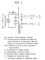
- Fig. 1 shows an equivalent circuit of an anti-ferroelectric liquid crystal device.
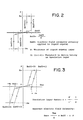
- Fig. 2 shows a simulation result on the steepness of threshold when alignment layer is absent.
- Fig. 3 shows a simulation result on the steepness of threshold when an alignment layer is present.
- Veff Effective voltage actually applied to liquid crystal.
- Fig. 1 shows an equivalent circuit which comprises an anti-ferroelectric liquid crystal which is an electric current source to generate a polarization current depending on an applied voltage, an alignment layer which is an electrostatic capacitor C to be connected to the liquid crystal in series, and a driving circuit that is an ideal voltage source.
- Vex is a driving voltage applied to a device
- Vc is a voltage generated between the upper and lower surfaces of an alignment layer by the charge of a polarization inverting current
- Veff is an effective voltage to be actually applied to the liquid crystal
- P is a spontaneous polarization of the liquid crystal
- S is an electrode area of the liquid crystal device
- d' is a thickness of the insulation(alignment) layer
- ⁇ ' is a dielectric constant of the insulation(alignment) layer.
- the voltage actually applied to the liquid crystal is lower than the externally applied voltage by a product of the polarization P of the liquid crystal, the thickness d' of the alignment layer and a reciprocal number 1/ ⁇ ' of the dielectric constant of the alignment layer.
- An anti-ferroelectric liquid crystal shows a hysteresis in optical response to a charged voltage, and four threshold voltages are thinkable with regard to the hysteresis.
- the measures that can be specifically taken include the use of an alignment layer having a high dielectric constant, the decreasing of the thickness of the alignment layer and the decreasing of the spontaneous polarization of the liquid crystal, as is clear from the above equations (5) and (6).
- the measures that can be specifically taken is therefore to decrease the thickness of the alignment layer and to decrease the spontaneous polarization of the liquid crystal.
- an anti-ferroelectric liquid crystal compound has a considerably large spontaneous polarization, and a liquid crystal compound having relatively excellent physical properties has a spontaneous polarization of 200 nC/cm 2 or more. Therefore, unless the thickness of the alignment layer is much decreased, the strain of the hysteresis is considerably large. However, when the thickness of the alignment layer is decreased, there occurs a problem that the alignment state of the liquid crystal molecules is too defective to secure a contrast.
- the spontaneous polarization of a liquid crystal compound is decreased by incorporating a proper compound having no spontaneous polarization into the liquid crystal compound, that is, by diluting the liquid crystal compound to decrease its concentration. Since, however, the response speed of a liquid crystal is determined by a product of an applied voltage and a spontaneous polarization, there occurs another new problem that the response speed decreases when the spontaneous polarization is simply decreased by dilution.
- the method of developing a liquid crystal material by combining a chiral dopant with a host liquid crystal which method was successful in the development of a ferroelectric liquid crystal display device, can be applied to the development of an anti-ferroelectric liquid crystal material as well, there can be developed a high-response material which has a low spontaneous polarization and has a low viscosity.
- a biphenyl-phenyl ester liquid crystal having a swallow-tail-shaped terminal group and containing a fluorine atom on the 3-position of a phenyl group is an achiral anti-ferroelectric liquid crystal compound which has an achiral anti-ferroelectric phase in a broad temperature range and whose achiral anti-ferroelectric phase has a high upper-limit temperature.
- a swallow-tail-shaped liquid crystal compound of the following general formula (1) wherein A is -O-, m is an integer of 6 to 10, and n is an integer of 2 to 4.
- a liquid crystal compound which is particularly preferable in that its achiral anti-ferroelectric phase shows a high upper-limit temperature and has a broad temperature range.
- n is an integer of 2 to 4
- the achiral anti-ferroelectric phase has a broad temperature range and shows a high upper-limit temperature when n is 2 or 3.
- the temperature range of the anti-ferroelectric phase includes room temperature and that the upper-limit temperature of the anti-ferroelectric phase is 50°C or higher.
- the present invention can provide a novel achiral anti-ferroelectric liquid crystal compound.
- the novel achiral anti-ferroelectric liquid crystal compound provided by the present invention can be converted to an optically active anti-ferroelectric liquid crystal by mixing it with an optically active compound as a chiral dopant.
- reaction mixture was poured into a cold water to precipitate a crystal, which was then subjected to filtration.
- the crystal was dried under vacuum and used in a subsequent step.
- the yield of the end product was 4.7 g.
- the solvent was distilled off, and the resultant crude product was purified by silica gel column chromatography using hexane/ethyl acetate as a solvent, to give 0.7 g of the end product.
- reaction mixture was diluted with 300 ml of ether, and the diluted mixture was washed consecutively with diluted hydrochloric acid, a IN sodium carbonate aqueous solution and water. An organic layer was dried over magnesium sulfate.
- the end product was obtained in the same manner as in Example 1 except that 3-pentanol was replaced with 2-ethyl-1-butanol.
- the end product was obtained in the same manner as in Example 1 except that 3-pentanol was replaced with 2-propyl-1-pentanol.
- Example 4 The end products were obtained in the same manner as in Example 1 except that n-nonyl bromide was replaced with n-hexyl bromide (Example 4), n-octyl bromide (Example 5) or n-decyl bromide (Example 6).
- Example 7 The end products were obtained in the same manner as in Example 1 except that n-nonyl bromide was replaced with n-hexyl bromide (Example 7), n-octyl bromide (Example 8) or n-decyl bromide (Example 9) and that 3-pentanol was replaced with 4-heptanol in each Example.
- a stirrer, a thermometer, a dropping funnel and a condenser were attached to a 1-liter four-necked flask.
- the flask was charged with 0.192 mol of biphenyl and 0.192 mol of aluminum chloride pulverized in advance, and 120 ml of carbon disulfide was added thereto.
- 0.192 mol of octanoyl chloride was added dropwise through the dropping funnel at room temperature over about 1 hour, the mixture was further stirred at room temperature for 3 hours.
- reaction mixture was poured into a mixture comprising 8 ml of concentrated hydrochloric acid and ice water, and the resulting mixture was extracted with dichloromethane. Thereafter, an extract was washed with water and then dried over anhydrous sodium sulfate.
- the solvent was distilled off to give 62.2 g of a crude product.
- the crude product was recrystallized from ethanol to give 50 g of octyl biphenyl ketone.
- a stirrer, a thermometer and a reflux condenser were attached to a 1-liter four-necked flask.
- the flask was charged with 0.147 mol of the above-obtained octyl biphenyl ketone, 0.521 mol of sodium hydroxide, 0.517 mol of hydrazine monohydrate and 300 ml of triethylene glycol, and the mixture was heated at 160°C for 1 hour with stirring to distill off water being formed.
- reaction mixture was continuously stirred under heating at 200°C for 2 hours.
- the crude product was purified with a silica gel column using hexane as a solvent to give 34.5 g of nonyl biphenyl.
- a stirrer, a thermometer, a dropping funnel and a condenser were attached to a 1-liter four-necked flask.
- the flask was charged with 0.107 mol of the above-obtained nonyl biphenyl, 0.111 mol of pulverized aluminum chloride and 110 ml of carbon disulfide.
- the reactor was coded, and 0.109 mol of oxalic acid chloride was added dropwise through the dropping funnel so as to reach a temperature of 10°C or lower. After the addition, the mixture was further stirred at room temperature for 2 hours.
- reaction mixture was poured into ice water and then extracted with dichloromethane. The solvent was then distilled off. To this were added 400 ml of tetrahydrofuran, 12 g of sodium hydroxide and 100 ml of water, and the mixture was refluxed under heating for 1 hour to be hydrolyzed.
- reaction mixture was poured into water, and concentrated hydrochloric acid was added to acidify the mixture.
- a precipitated solid was recovered by filtration and air-dried to give about 40 g of a crude product.
- the crude product was recrystallized from toluene to give 17.5 g of the end product.
- Table 2 also shows the results of identifying liquid crystal phases.
- the liquid crystal phases were identified by texture observation and measurement with a DSC (differential scanning calorimeter).
Landscapes
- Chemical & Material Sciences (AREA)
- Organic Chemistry (AREA)
- Crystallography & Structural Chemistry (AREA)
- Engineering & Computer Science (AREA)
- Materials Engineering (AREA)
- Liquid Crystal Substances (AREA)
- Organic Low-Molecular-Weight Compounds And Preparation Thereof (AREA)
Description
- The present invention relates to a novel liquid crystal compound having an achiral anti-ferroelectric phase.
- A liquid crystal display device has so far been used mainly to a variety of small-sized display devices on account of its low-voltage operation, low-power consumption and display capability with a thin screen. Further, with the recent application and increased use of a liquid crystal display device to/in the fields of information, office automation-related machines and equipment, and television sets, demands are rapidly increasing for high-performance and large-sized liquid crystal display devices having a larger display capacity and a higher display quality than those of a conventional CRT display device.
- However, as long as a nematic liquid crystal compound available at present is used in a display device, even with an active matrix driven liquid crystal display device (TFT) used in a liquid crystal television set, it is not easy to increase its size and decrease its production cost due to its complicated production process and a low yield. In a simple matrix driven STN liquid crystal display device (STN), the driving of a large display capacity is not necessarily easy and its response time is also limited, so that the display of video frames at a high duty ratio is therefore difficult. Consequently, it is difficult to say at present that a nematic liquid crystal display device can satisfy demands for the above high-performance and large-sized liquid crystal display device.
- Further, both TFT and STN display devices using a nematic liquid crystal compound have a serious problem with regard to their narrow viewing angle. Although a variety of solutions are proposed, it is difficult to find out a radical solution as long as a nematic liquid crystal compound is used.
- Under the circumstances, a liquid crystal display device for which a ferroelectric liquid crystal is used has been attracting attention as a liquid crystal display device with a high response and a wide viewing angle. A surface-stabilized ferroelectric liquid crystal (SSFLC) device disclosed by Clark and Lagerwall has been attracting attention in that it has a fast response and a wide viewing angle which have not been achieved in the past. Its switching characteristics have been studied in detail, and a number of ferroelectric liquid crystal compounds have been synthesized for optimizing various physical property constants. When a ferroelectric liquid crystal compound is used for a liquid crystal display device, however, a special devising is required with regard to the alignment of a liquid crystal for obtaining a practically acceptable contrast due to its insufficient threshold characteristic and chevron-structured layer. Further, the alignment control of liquid crystal molecules is so difficult that it is not easy to accomplish the bistability, which is one of the greatest characteristics of SSFLC, with high reproducibility. Further, it is difficult to restore the alignment destroyed by a mechanical shock. It is therefore essential to overcome the above problems for its practical use.
- As described above, various efforts including the development of a new mode have been made for attaining a larger-sized and higher-resolution liquid crystal device. Under the circumstances, however, developments of devices having switching mechanisms totally different from that of SSFLC are also under way. For example, switching among tristable states of a liquid crystal compound having an anti-ferroelectric phase (to be referred to as "anti-ferroelectric liquid crystal compound" hereinafter) is one of these new switching mechanisms (Japanese Journal of Applied Physics, Vol. 27, pp. L729, (1988)).
- A liquid crystal display device using an anti-ferroelectric liquid crystal compound has three stable states, i.e., two uniform states (Ur, Ul) observed in a ferroelectric liquid crystal device and a third state. Chandani et al report that the above third state is an anti-ferroelectric phase (Japanese Journal of Applied Physics, Vol. 28, pp. L1261, (1989), Japanese Journal of Applied Physics, Vol. 28, pp. L1265, (1989)).
- The above switching among tristable states is the first characteristic of an anti-ferroelectric liquid crystal device.
- The second characteristic of the anti-ferroelectric liquid crystal device is that a sharp threshold voltage exists with respect to an applied voltage. Further, the anti-ferroelectric liquid crystal device has a memory effect, which is the third characteristic of the anti-ferroelectric liquid crystal device.
- The above excellent characteristics serve to accomplish a liquid crystal display device having a fast response and a good contrast.
- The anti-ferroelectric liquid crystal has another great characteristic in that its layer structure easily performs switching when an electric field is applied (Japanese Journal of Applied Physics, Vol. 28, pp. L119, (1989), Japanese Journal of Applied Physics, Vol. 29, pp. L111, (1990)).
- The above characteristics permit the production of a liquid crystal display device free of defects and capable of self-restoring an alignment, and a liquid crystal device having an excellent contrast can be attained.
- As an anti-ferroelectric liquid crystal compound, there are known compounds disclosed in JP-A-1-213390, JP-A-1-316339, JP-A-1-316367, JP-A-1-316372, JP-A-2-28128 and "Liquid Crystals", Vol. 6, pp. 167 (1989). The number of anti-ferroelectric liquid crystal compounds which have been so far known is not so large as that of ferroelectric liquid crystal compounds, while anti-ferroelectric liquid crystal compounds are increasing in number with the development in their studies.
- On the other hand, as a progress has been made in the development of a liquid crystal display device using an anti-ferroelectric liquid crystal compound, there have been revealed defects unique to an anti-ferroelectric liquid crystal.
- One of the defects is large spontaneous polarization. That is, there occurs a problem which will be discussed below when the spontaneous polarization is large.
- Practically, it is preferable that an anti-ferroelectric liquid crystal is a material which gives a high steepness of optical transmittance change against applied voltage when adapted to a liquid crystal display device. Further, it has been experimentally recognized that the steepness of the liquid crystal display device is greatly related to the thickness of each of an insulation layer and an alignment layer.
- It has been studied what factors can help explain the above phenomenon. In this studies, both an insulation layer and an alignment layer together will be referred to as "alignment layer".
- Fig. 1 shows an equivalent circuit of an anti-ferroelectric liquid crystal device.
- Fig. 2 shows a simulation result on the steepness of threshold when alignment layer is absent.
- Fig. 3 shows a simulation result on the steepness of threshold when an alignment layer is present.
- The symbols used in each of the drawings represent the following.
- Vex: Driving voltage applied to device.
- Vc: Voltage generated between an upper surface and a lower surface of an insulation layer when polarization inverting current is charged.
-
- Veff: Effective voltage actually applied to liquid crystal.
- P: Polarization of liquid crystal
- ip: Polarization inverting current
- S: Electrode area of liquid crystal device
- d': Thickness of insulation layer
- ε': Dielectric constant of insulation layer
- Eeff: Intensity of electric field actually applied to liquid crystal
- d: Thickness of liquid crystal layer
- Ci(i = 1-4): Threshold voltage in device having no insulation layer
- α: Insulation layer factor
- Eex: Apparent electric field intensity
-
- The equivalent circuit of an anti-ferroelectric liquid crystal display device will be explained first with reference to Fig. 1.
- Fig. 1 shows an equivalent circuit which comprises an anti-ferroelectric liquid crystal which is an electric current source to generate a polarization current depending on an applied voltage, an alignment layer which is an electrostatic capacitor C to be connected to the liquid crystal in series, and a driving circuit that is an ideal voltage source.
- In Fig. 1, Vex is a driving voltage applied to a device, Vc is a voltage generated between the upper and lower surfaces of an alignment layer by the charge of a polarization inverting current, Veff is an effective voltage to be actually applied to the liquid crystal, P is a spontaneous polarization of the liquid crystal, S is an electrode area of the liquid crystal device, d' is a thickness of the insulation(alignment) layer, and ε' is a dielectric constant of the insulation(alignment) layer.
- Vc is calculated according to the following equation (1).
- On the basis of the above equation, Veff is expressed by the following equation (2).
- As shown in the equation (2), the voltage actually applied to the liquid crystal is lower than the externally applied voltage by a product of the polarization P of the liquid crystal, the thickness d' of the alignment layer and a
reciprocal number 1/ε' of the dielectric constant of the alignment layer. - Then, when a thickness of the liquid crystal layer filled in a liquid crystal cell is taken as d, an electric field Eeff actually applied to the liquid crystal is expressed by the following equation (3).
- An apparent electric field intensity Eex is expressed by the following equation (4).
- An anti-ferroelectric liquid crystal shows a hysteresis in optical response to a charged voltage, and four threshold voltages are thinkable with regard to the hysteresis.
- When no alignment layer is present, the second term in the equation (4) is 0, and hence Eex = Eeff. Each threshold is Eeff (= Eex), and in this case, these thresholds do not incline to an electric field. Fig. 2 shows this appearance.
- When an alignment layer is present, the equation (4) is modified to obtain the following equation (6).
- That is, an effective electric field exerting on the liquid crystal is lower than the applied electric field Eex by α·P. As a result, the hysteresis is strained to a great extent due to the contribution of the α·P as shown in Fig. 3.
- The above studies show that the strain of hysteresis is greatly caused by the interaction of the spontaneous polarization and the alignment layer. For obtaining a liquid crystal device having the strain of hysteresis reduced, therefore, it is effective to decrease the above interaction so as to make it as small as possible.
- For the above purpose, the measures that can be specifically taken include the use of an alignment layer having a high dielectric constant, the decreasing of the thickness of the alignment layer and the decreasing of the spontaneous polarization of the liquid crystal, as is clear from the above equations (5) and (6). In the above measures, it is very difficult to select an alignment layer having a high dielectric constant, since few kind of materials having a high dielectric constant are available for industrial use. The measures that can be specifically taken is therefore to decrease the thickness of the alignment layer and to decrease the spontaneous polarization of the liquid crystal.
- Generally, an anti-ferroelectric liquid crystal compound has a considerably large spontaneous polarization, and a liquid crystal compound having relatively excellent physical properties has a spontaneous polarization of 200 nC/cm2 or more. Therefore, unless the thickness of the alignment layer is much decreased, the strain of the hysteresis is considerably large. However, when the thickness of the alignment layer is decreased, there occurs a problem that the alignment state of the liquid crystal molecules is too defective to secure a contrast.
- The measure for correcting the strain of the hysteresis by decreasing the thickness of the alignment layer is therefore considerably limited, and it is very difficult to use the above measure for practical solution.
- On the other hand, there is employed a method in which the spontaneous polarization of a liquid crystal compound is decreased by incorporating a proper compound having no spontaneous polarization into the liquid crystal compound, that is, by diluting the liquid crystal compound to decrease its concentration. Since, however, the response speed of a liquid crystal is determined by a product of an applied voltage and a spontaneous polarization, there occurs another new problem that the response speed decreases when the spontaneous polarization is simply decreased by dilution.
- Under the circumstances, for obtaining a device having a decreased strain of hysteresis, attempts have been so far made to develop an anti-ferroelectric liquid crystal compound having a low spontaneous polarization, a low threshold voltage and a low viscosity, but it is a current situation that no satisfactory achievements have been obtained.
- On the other hand, if the method of developing a liquid crystal material by combining a chiral dopant with a host liquid crystal, which method was successful in the development of a ferroelectric liquid crystal display device, can be applied to the development of an anti-ferroelectric liquid crystal material as well, there can be developed a high-response material which has a low spontaneous polarization and has a low viscosity.
- No achiral anti-ferroelectric liquid crystal was found in the past, but in recent years, an achiral anti-ferroelectric liquid crystal phase has been found in the following compounds.
- (1) C9H19-O-Ph-C≡C-COO-Ph-Ph-COO-CH(C3H7)2
- I(70)SA(55)SCA'(40)Cr
- Nishiyama et al., J. MATER.CHEM., 1992, 2(10), 1015
- (2) C8H17-O-Ph-Ph-COO-Ph-COO-CH(C6H13)2
I(81)SA(61.9)SCA'(?)Cr, Melting point: 69.7°C - (3) C8H17-O-Ph-Ph-COO-Ph-COO-CH(C3H7)2
- I(119.7)SA(103.2)SCA'(?)Cr, Melting point 80.0°C
- Y. Ouchi et al., J. MATER.CHEM., 1995, 5(12), 2297
- (4) C8H17-O-Ph-Ph-COO-Ph(2F)-COO-CH(CnH2n+1)2
- n = 2; I(108.6)SA(82.2)SCA'(32)Cr
- n = 3; I(72.9)SA(56.8)SCA'(40)Cr
- n = 4; I(58.1)SA(45.7)SCA'(40)Cr
- C. J. Booth et al., Liquid Crystals, 1996, 20(4), 387
-
- In the above formulae, -Ph- is a 1,4-phenylene group and -Ph(2F)- is a 1,4-phenylene group having a fluorine atom on the 2-position. In the above phase sequences, parenthesized value shows a phase transition temperature (°C), I is an isotropic phase, SA is a smectic A phase, SCA' is an achiral anti-ferroelectric phase, and Cr is a crystal phase.
- The number of achiral anti-ferroelectric liquid crystals which have been so far found is very small as described above. In terms of chemical structure, it seems that compounds which have an alkyl group having a swallow-tail-shaped branched terminals in place of an optically active group of a chiral anti-ferroelectric liquid crystal exhibit an achiral anti-ferroelectric phase. On the other hand, as is clear from the above phase sequences, in view of practical use, those achiral anti-ferroelectric liquid crystal compounds which have been so far found have problems that the upper-limit temperature of their anti-ferroelectric phase is low and that the temperature range of their anti-ferroelectric phase is narrow, so that it is problematic to use them as a host liquid crystal.
- The present invention has been invented from the above points of view, and has been completed by finding that a biphenyl-phenyl ester liquid crystal having a swallow-tail-shaped terminal group and containing a fluorine atom on the 3-position of a phenyl group is an achiral anti-ferroelectric liquid crystal compound which has an achiral anti-ferroelectric phase in a broad temperature range and whose achiral anti-ferroelectric phase has a high upper-limit temperature.
- That is, according to the present invention, there is provided a swallow-tail-shaped liquid crystal compound of the following general formula (1),wherein A is -O-, m is an integer of 6 to 10, and n is an integer of 2 to 4.

- By the compound of the above general formula (1) there can be provided a liquid crystal compound which is particularly preferable in that its achiral anti-ferroelectric phase shows a high upper-limit temperature and has a broad temperature range. n is an integer of 2 to 4, and the achiral anti-ferroelectric phase has a broad temperature range and shows a high upper-limit temperature when n is 2 or 3. In view of practical use, it is preferred that the temperature range of the anti-ferroelectric phase includes room temperature and that the upper-limit temperature of the anti-ferroelectric phase is 50°C or higher.
- The present invention can provide a novel achiral anti-ferroelectric liquid crystal compound. The novel achiral anti-ferroelectric liquid crystal compound provided by the present invention can be converted to an optically active anti-ferroelectric liquid crystal by mixing it with an optically active compound as a chiral dopant.
- The present invention will be explained in more detail with reference to the following Examples and Comparative Examples, while the present invention shall not be limited thereto.
- Preparation of 3-fluoro-4-(1-ethylpropyloxycarbonyl)phenyl=4'-n-nonyloxybiphenyl-4-carboxylate
- 10.0 Grams of 4-(4'-hydroxy)biphenylcarboxylic acid and 17.3 g of n-nonyl bromide were added to a mixture comprising 1,500 ml(milliliter) of ethanol and 200 ml of water, and the mixture was allowed to react under reflux for 10 hours. Thereafter, 500 ml of water was added, and the mixture was stirred for 3 hours.
- After the completion of the reaction, concentrated hydrochloric acid was added to acidify the reaction mixture, then, 500 ml of a solvent was distilled off, and the remainder of the mixture was cooled to room temperature to give a white solid. The white solid was fully washed with water and then recrystallized from chloroform to give 12.8 g of an end product in the form of a white crystal.
- 4.3 Grams of 2-fluoro-4-hydroxybenzoic acid and 8.4 g of acetic acid anhydride were placed in a two-necked flask and mixed therein. While the mixture was being cooled with water, five drops of sulfuric acid were added. After the termination of heat generation, the mixture was heated at 80°C for 30 minutes.
- Then, the reaction mixture was poured into a cold water to precipitate a crystal, which was then subjected to filtration. The crystal was dried under vacuum and used in a subsequent step. The yield of the end product was 4.7 g.
- 1.0 Gram of 4-acetoxy-2-fluorobenzoic acid was added to 7 ml of thionyl chloride, and the mixture was allowed to react under reflux for 5 hours. Thereafter, excessive thionyl chloride was distilled off, and a mixture comprising 1 ml of pyridine, 4 ml of dry ether and 0.6 g of 3-pentanol was added dropwise to the above mixture. After the addition, the resulting mixture was stirred at room temperature for one day and diluted with 200 ml of ether, and an organic layer was washed consecutively with diluted hydrochloric acid, a IN sodium hydroxide aqueous solution and water, and dried over magnesium sulfate.
- The solvent was distilled off, and the resultant crude product was purified by silica gel column chromatography using hexane/ethyl acetate as a solvent, to give 0.7 g of the end product.
- 0.5 Gram of the compound obtained in the above (3) was dissolved in 30 ml of ethanol, and 1.5 g of benzylamine was added dropwise thereto. Further, the mixture was stirred at room temperature for one day and diluted with 300 ml of ether, and the diluted mixture was washed with diluted hydrochloric acid and then with water and dried over magnesium sulfate.
- The solvent was distilled off, and silica gel column chromatography was used for purification to give 0.3 g of the end product.
- To 0.5 g of the compound obtained in the above (1) was added 10 ml of thionyl chloride, and the mixture was refluxed under heating for 10 hours. Thereafter, excessive thionyl chloride was distilled off, and 10 ml of pyridine and 25 ml of toluene were added to the remaining of the mixture. Then, a solution of 0.3 g of the compound obtained in the above (4) in 25 ml of benzene solution was added dropwise thereto, and the resulting mixture was allowed to react at room temperature for 10 hours.
- After the completion of the reaction, the reaction mixture was diluted with 300 ml of ether, and the diluted mixture was washed consecutively with diluted hydrochloric acid, a IN sodium carbonate aqueous solution and water. An organic layer was dried over magnesium sulfate.
- Thereafter, the solvent was distilled off, and silica gel column chromatography was used for isolation. Finally, an isolated product was recrystalllized from ethanol to give 0.1 g of the end product.
- Preparation of 3-fluoro-4-(1-propylbutyloxycarbonyl)phenyl=4'-n-nonyloxybiphenyl-4-carboxylate
- Preparation of 3-fluoro-4-(1-butylpentyloxycarbonyl)phenyl=4'-n-nonyloxybiphenyl-4-carboxylate
- The end products were obtained in the same manner as in Example 1 except that 3-pentanol was replaced with 4-heptanol (Example 2) or 5-nonanol (Example 3).
- Preparation of 3-fluoro-4-(2-ethylbutyloxycarbonyl)phenyl=4'-n-nonyloxybiphenyl-4-carboxylate (CE1)
- The end product was obtained in the same manner as in Example 1 except that 3-pentanol was replaced with 2-ethyl-1-butanol.
- Preparation of 3-fluoro-4-(2-propylpentyloxycarbonyl)phenyl=4'-n-nonyloxybiphenyl-4-carboxylate (CE2)
- The end product was obtained in the same manner as in Example 1 except that 3-pentanol was replaced with 2-propyl-1-pentanol.
- Preparation of 3-fluoro-4-(1-ethylpropyloxycarbonyl)phenyl=4'-n-hexyloxybiphenyl-4-carboxylate
- Preparation of 3-fluoro-4-(1-ethylpropyloxycarbonyl)phenyl=4'-n-octyloxybiphenyl-4-carboxylate
- Preparation of 3-fluoro-4-(1-ethylpropyloxycarbonyl)phenyl=4'-n-decyloxybiphenyl-4-carboxylate
- The end products were obtained in the same manner as in Example 1 except that n-nonyl bromide was replaced with n-hexyl bromide (Example 4), n-octyl bromide (Example 5) or n-decyl bromide (Example 6).
- Preparation of 3-fluoro-4-(1-propylbutyloxycarbonyl)phenyl=4'-n-hexyloxybiphenyl-4-carboxylate
- Preparation of 3-fluoro-4-(1-propylbutyloxycarbonyl)phenyl=4'-n-octyloxybiphenyl-4-carboxylate
- Preparation of 3-fluoro-4-(1-propylbutyloxycarbonyl)phenyl=4'-n-decyloxybiphenyl-4-carboxylate
- The end products were obtained in the same manner as in Example 1 except that n-nonyl bromide was replaced with n-hexyl bromide (Example 7), n-octyl bromide (Example 8) or n-decyl bromide (Example 9) and that 3-pentanol was replaced with 4-heptanol in each Example.
- (Formula (1): A = single bond (-), m = 9, n = 3 (CE3))
- Preparation of 3-fluoro-4-(1-propylbutyloxycarbonyl)phenyl=4'-n-nonylbiphenyl-4-carboxylate
- The end product was obtained in the same manner as in Example 1 except that 4-(4'-n-nonyl)biphenylcarboxylic acid prepared below was used.
- A stirrer, a thermometer, a dropping funnel and a condenser were attached to a 1-liter four-necked flask. The flask was charged with 0.192 mol of biphenyl and 0.192 mol of aluminum chloride pulverized in advance, and 120 ml of carbon disulfide was added thereto. After 0.192 mol of octanoyl chloride was added dropwise through the dropping funnel at room temperature over about 1 hour, the mixture was further stirred at room temperature for 3 hours.
- The reaction mixture was poured into a mixture comprising 8 ml of concentrated hydrochloric acid and ice water, and the resulting mixture was extracted with dichloromethane. Thereafter, an extract was washed with water and then dried over anhydrous sodium sulfate.
- The solvent was distilled off to give 62.2 g of a crude product. The crude product was recrystallized from ethanol to give 50 g of octyl biphenyl ketone.
- A stirrer, a thermometer and a reflux condenser were attached to a 1-liter four-necked flask. The flask was charged with 0.147 mol of the above-obtained octyl biphenyl ketone, 0.521 mol of sodium hydroxide, 0.517 mol of hydrazine monohydrate and 300 ml of triethylene glycol, and the mixture was heated at 160°C for 1 hour with stirring to distill off water being formed.
- Then, the reaction mixture was continuously stirred under heating at 200°C for 2 hours.
- After allowed to cool, the reaction mixture was poured into water and then extracted with toluene. An extract was washed with water, and the solvent was then distilled off to give 47.6 g of a crude product.
- The crude product was purified with a silica gel column using hexane as a solvent to give 34.5 g of nonyl biphenyl.
- A stirrer, a thermometer, a dropping funnel and a condenser were attached to a 1-liter four-necked flask. The flask was charged with 0.107 mol of the above-obtained nonyl biphenyl, 0.111 mol of pulverized aluminum chloride and 110 ml of carbon disulfide.
- The reactor was coded, and 0.109 mol of oxalic acid chloride was added dropwise through the dropping funnel so as to reach a temperature of 10°C or lower. After the addition, the mixture was further stirred at room temperature for 2 hours.
- The reaction mixture was poured into ice water and then extracted with dichloromethane. The solvent was then distilled off. To this were added 400 ml of tetrahydrofuran, 12 g of sodium hydroxide and 100 ml of water, and the mixture was refluxed under heating for 1 hour to be hydrolyzed.
- After allowed to cool, the reaction mixture was poured into water, and concentrated hydrochloric acid was added to acidify the mixture.
- A precipitated solid was recovered by filtration and air-dried to give about 40 g of a crude product. The crude product was recrystallized from toluene to give 17.5 g of the end product.
- (Formula (1): A = -COO-, m = 9, n = 3 (CE4)) Preparation of 3-fluoro-4-(1-propylbutyloxycarbonyl)phenyl=4'-n-decanoyloxybiphenyl-4-carboxylate
- The end product was obtained in the same manner as in Example 1 except that 4-(4'-n-decanoyloxy)biphenylcarboxylic acid prepared below was used.
- (1) Preparation of 4-(4'-n-decanoyloxy)biphenylcarboxylic acid
- 10.0 Grams of 4-(4'-hydroxy)biphenylcarboxylic acid, 9.8 g of n-decanoic acid chloride, 16 ml(milliliter) of triethylamine and 1 g of dimethylaminopyridine were dissolved in 150 ml of dichloromethane, and the mixture was stirred at room temperature for one day.
- After the completion of the reaction, 50 ml of 10 % hydrochloric acid was added, and the mixture was extracted with 100 ml of ether three times. An organic layer was washed with 100 ml of sodium chloride aqueous solution three times and then dried over anhydrous sodium sulfate.
- The solvent was distilled off, and a remainder was washed with 400 ml of hexane to give the end product.
- The formulae of the compounds (E1 to E9) obtained in Examples 1 to 9 and the compounds (CE1 to CE4) obtained in Comparative Examples 1 to 4 are shown below. Table 1 shows 1H-NMR spectrum data of these compounds.
- Table 2 also shows the results of identifying liquid crystal phases. The liquid crystal phases were identified by texture observation and measurement with a DSC (differential scanning calorimeter).


Claims (3)
- A swallow-tail-shaped liquid crystal compound of the following general formula (1),wherein A is -O-, m is an integer of 6 to 10, and n is an integer of 2 to 4.

- The compound of claim 1, wherein n in the general formula (1) is an integer of 2 or 3.
- The compound of claim 1, which has an achiral anti-ferroelectric phase whose lower limit temperature is lower than or equal to room temperature and whose upper limit temperature is higher than or equal to 50°C.
Applications Claiming Priority (12)
| Application Number | Priority Date | Filing Date | Title |
|---|---|---|---|
| JP16428697 | 1997-06-20 | ||
| JP16428697 | 1997-06-20 | ||
| JP164286/97 | 1997-06-20 | ||
| JP21188497 | 1997-08-06 | ||
| JP211884/97 | 1997-08-06 | ||
| JP21188497 | 1997-08-06 | ||
| JP27731697 | 1997-10-09 | ||
| JP277317/97 | 1997-10-09 | ||
| JP27731797 | 1997-10-09 | ||
| JP27731797 | 1997-10-09 | ||
| JP27731697 | 1997-10-09 | ||
| JP277316/97 | 1997-10-09 |
Publications (2)
| Publication Number | Publication Date |
|---|---|
| EP0885876A1 EP0885876A1 (en) | 1998-12-23 |
| EP0885876B1 true EP0885876B1 (en) | 2001-09-05 |
Family
ID=27473920
Family Applications (1)
| Application Number | Title | Priority Date | Filing Date |
|---|---|---|---|
| EP98111072A Expired - Lifetime EP0885876B1 (en) | 1997-06-20 | 1998-06-17 | Swallow-tail-shaped liquid crystal compound |
Country Status (5)
| Country | Link |
|---|---|
| US (1) | US5976409A (en) |
| EP (1) | EP0885876B1 (en) |
| KR (1) | KR19990007176A (en) |
| DE (1) | DE69801549T2 (en) |
| TW (1) | TW473538B (en) |
Families Citing this family (10)
| Publication number | Priority date | Publication date | Assignee | Title |
|---|---|---|---|---|
| DE69800451T2 (en) * | 1997-05-22 | 2001-05-03 | Mitsubishi Gas Chemical Co | Antiferroelectric liquid crystal composition |
| US6197389B1 (en) * | 1998-07-24 | 2001-03-06 | Mitsubishi Gas Chemical Company Inc | Ferrielectric liquid crystal compound |
| JP2000109451A (en) * | 1998-10-05 | 2000-04-18 | Mitsubishi Gas Chem Co Inc | Ferrielectric liquid crystal compound |
| US6217954B1 (en) * | 1998-10-12 | 2001-04-17 | Mitsubishi Gas Chemical Co Inc | Phenyl triester compound and anti-ferroelectric liquid crystal composition containing the same |
| TW448228B (en) * | 1999-01-20 | 2001-08-01 | Chunghwa Picture Tubes Ltd | A novel chiral swallow-tailed liquid crystal material |
| US6372308B1 (en) * | 1999-01-28 | 2002-04-16 | Mitsubishi Gas Chemical Company Inc | Liquid crystal composition |
| US6870163B1 (en) | 1999-09-01 | 2005-03-22 | Displaytech, Inc. | Ferroelectric liquid crystal devices using materials with a de Vries smectic A phase |
| US7083832B2 (en) | 2000-09-01 | 2006-08-01 | Displaytech, Inc. | Partially fluorinated liquid crystal material |
| US6703082B1 (en) | 2001-06-20 | 2004-03-09 | Displaytech, Inc. | Bookshelf liquid crystal materials and devices |
| KR20070107319A (en) * | 2006-05-02 | 2007-11-07 | 삼성전자주식회사 | Liquid crystal display |
Family Cites Families (16)
| Publication number | Priority date | Publication date | Assignee | Title |
|---|---|---|---|---|
| US4943386A (en) * | 1985-01-09 | 1990-07-24 | Dainippon Ink & Chemicals, Inc. | Liquid crystalline compounds having substituents |
| US5424005A (en) * | 1988-02-02 | 1995-06-13 | Showa Shell Sekiyu K.K. | Liquid crystal compounds |
| JP2526085B2 (en) * | 1988-02-22 | 1996-08-21 | チッソ株式会社 | Ferroelectric liquid crystal composition and liquid crystal display device |
| JPH01316339A (en) * | 1988-02-26 | 1989-12-21 | Showa Shell Sekiyu Kk | Liquid crystal substance |
| JP2760836B2 (en) * | 1988-03-09 | 1998-06-04 | 昭和シェル石油株式会社 | Dioxane liquid crystal material |
| JP2792894B2 (en) * | 1988-03-28 | 1998-09-03 | 昭和シェル石油株式会社 | Liquid crystal material having heterocyclic skeleton |
| DE68916105T2 (en) * | 1988-04-28 | 1994-11-17 | Showa Shell Sekiyu | Liquid crystal compounds with naphthalene nucleus. |
| US5098602A (en) * | 1988-05-11 | 1992-03-24 | Nippon Mining Co., Ltd. | Novel halogen-containing ester compounds, and their intermediates, and method of producing the same as well as liquid crystal compositions containing the same and light switching elements |
| EP0450595B1 (en) * | 1990-04-04 | 1995-03-01 | Mitsubishi Gas Chemical Company, Inc. | Liquid crystal compound and liquid crystal display device |
| DE69319032T2 (en) * | 1992-08-05 | 1998-10-08 | Mitsubishi Gas Chemical Co | Antiferroelectric liquid crystal composition and liquid crystal display device |
| DE69308427T2 (en) * | 1992-08-19 | 1997-08-21 | Mitsubishi Gas Chemical Co | Antiferroelectric liquid crystal and liquid crystal display device |
| GB2278841A (en) * | 1993-06-11 | 1994-12-14 | Secr Defence | Liquid crystal compounds, mixtures and devices |
| GB9325438D0 (en) * | 1993-12-13 | 1994-02-16 | Secr Defence | Ferroelectric liquid crystal devices |
| JP3501866B2 (en) * | 1994-07-19 | 2004-03-02 | 株式会社日本自動車部品総合研究所 | Antiferroelectric liquid crystal composition and liquid crystal display device using the same |
| EP0738704B1 (en) * | 1995-04-21 | 2001-02-21 | Mitsubishi Gas Chemical Company, Inc. | Phenyl ester compound and liquid crystal composition containing the same |
| TW448229B (en) * | 1996-05-14 | 2001-08-01 | Mitsubishi Gas Chemical Co | Optically active compound, liquid crystal compositions containing the optically active compound, and liquid crystal display device |
-
1998
- 1998-06-17 EP EP98111072A patent/EP0885876B1/en not_active Expired - Lifetime
- 1998-06-17 DE DE69801549T patent/DE69801549T2/en not_active Expired - Fee Related
- 1998-06-18 TW TW087109761A patent/TW473538B/en not_active IP Right Cessation
- 1998-06-19 US US09/099,772 patent/US5976409A/en not_active Expired - Fee Related
- 1998-06-20 KR KR1019980023253A patent/KR19990007176A/en not_active Application Discontinuation
Also Published As
| Publication number | Publication date |
|---|---|
| TW473538B (en) | 2002-01-21 |
| DE69801549T2 (en) | 2002-04-25 |
| EP0885876A1 (en) | 1998-12-23 |
| DE69801549D1 (en) | 2001-10-11 |
| US5976409A (en) | 1999-11-02 |
| KR19990007176A (en) | 1999-01-25 |
Similar Documents
| Publication | Publication Date | Title |
|---|---|---|
| EP0450595A1 (en) | Liquid crystal compound and liquid crystal display device | |
| EP0885876B1 (en) | Swallow-tail-shaped liquid crystal compound | |
| US5728864A (en) | Liquid crystal compound having ferrielectric phase and liquid crystal composition | |
| EP0487093B1 (en) | Liquid crystal compound and liquid crystal display device | |
| US5938973A (en) | Swallow-tailed compound and ferrielectric liquid crystal composition containing the same | |
| EP0497297B1 (en) | Liquid crystal compound and liquid crystal display device | |
| JPH09165356A (en) | Antiferroelectric liquid crystal compound and antiferroelectric liquid crystal composition | |
| US5980780A (en) | Racemic compound and anti-ferroelectric liquid crystal composition containing the compound | |
| EP0829469B1 (en) | Racemic compound and anti-ferroelectric liquid crystal composition | |
| EP0435240B1 (en) | Liquid crystal compound | |
| US5340498A (en) | Anti-ferroelectric liquid crystal and liquid crystal display device | |
| US5264150A (en) | Optically active alcohol, process for producing same and liquid crystal compound using same | |
| US5968413A (en) | Anti-ferroelectric liquid crystal compounds | |
| US5985172A (en) | Racemic compound and anti-ferroelectric liquid crystal composition containing the compound | |
| US5210267A (en) | Optically-active aliphatic β-halogen substituted carboxylic acid 4'-(4-alkoxybenzyloxy)biphenyl thioester compounds and process for the preparation thereof | |
| JP2900599B2 (en) | Liquid crystal material | |
| EP0354355A1 (en) | Optically active compound and liquid crystal composition | |
| JP3255180B2 (en) | Fluorine-substituted liquid crystal material | |
| EP0402233B1 (en) | Liquid crystal compounds | |
| JPH11171838A (en) | Swallowtail-type liquid crystal compound | |
| JPH0558959A (en) | Liquid crystal substance | |
| JPH10101617A (en) | Antiferroelectric liquid crystal compound | |
| JPH0539246A (en) | Fluorine-substituted liquid crystal substance | |
| JPH07316101A (en) | Antiferroelectric liquid crystal substance | |
| JPH07316100A (en) | Antiferromagnetic liquid crystal substance |
Legal Events
| Date | Code | Title | Description |
|---|---|---|---|
| PUAI | Public reference made under article 153(3) epc to a published international application that has entered the european phase |
Free format text: ORIGINAL CODE: 0009012 |
|
| AK | Designated contracting states |
Kind code of ref document: A1 Designated state(s): DE FR GB |
|
| AX | Request for extension of the european patent |
Free format text: AL;LT;LV;MK;RO;SI |
|
| 17P | Request for examination filed |
Effective date: 19990319 |
|
| AKX | Designation fees paid |
Free format text: DE FR GB |
|
| 17Q | First examination report despatched |
Effective date: 19991111 |
|
| GRAG | Despatch of communication of intention to grant |
Free format text: ORIGINAL CODE: EPIDOS AGRA |
|
| GRAG | Despatch of communication of intention to grant |
Free format text: ORIGINAL CODE: EPIDOS AGRA |
|
| GRAG | Despatch of communication of intention to grant |
Free format text: ORIGINAL CODE: EPIDOS AGRA |
|
| GRAH | Despatch of communication of intention to grant a patent |
Free format text: ORIGINAL CODE: EPIDOS IGRA |
|
| GRAH | Despatch of communication of intention to grant a patent |
Free format text: ORIGINAL CODE: EPIDOS IGRA |
|
| GRAA | (expected) grant |
Free format text: ORIGINAL CODE: 0009210 |
|
| AK | Designated contracting states |
Kind code of ref document: B1 Designated state(s): DE FR GB |
|
| REF | Corresponds to: |
Ref document number: 69801549 Country of ref document: DE Date of ref document: 20011011 |
|
| ET | Fr: translation filed | ||
| REG | Reference to a national code |
Ref country code: GB Ref legal event code: IF02 |
|
| PGFP | Annual fee paid to national office [announced via postgrant information from national office to epo] |
Ref country code: FR Payment date: 20020610 Year of fee payment: 5 |
|
| PGFP | Annual fee paid to national office [announced via postgrant information from national office to epo] |
Ref country code: GB Payment date: 20020612 Year of fee payment: 5 |
|
| PGFP | Annual fee paid to national office [announced via postgrant information from national office to epo] |
Ref country code: DE Payment date: 20020626 Year of fee payment: 5 |
|
| PLBE | No opposition filed within time limit |
Free format text: ORIGINAL CODE: 0009261 |
|
| STAA | Information on the status of an ep patent application or granted ep patent |
Free format text: STATUS: NO OPPOSITION FILED WITHIN TIME LIMIT |
|
| 26N | No opposition filed | ||
| PG25 | Lapsed in a contracting state [announced via postgrant information from national office to epo] |
Ref country code: GB Free format text: LAPSE BECAUSE OF NON-PAYMENT OF DUE FEES Effective date: 20030617 |
|
| PG25 | Lapsed in a contracting state [announced via postgrant information from national office to epo] |
Ref country code: DE Free format text: LAPSE BECAUSE OF NON-PAYMENT OF DUE FEES Effective date: 20040101 |
|
| GBPC | Gb: european patent ceased through non-payment of renewal fee |
Effective date: 20030617 |
|
| PG25 | Lapsed in a contracting state [announced via postgrant information from national office to epo] |
Ref country code: FR Free format text: LAPSE BECAUSE OF NON-PAYMENT OF DUE FEES Effective date: 20040227 |
|
| REG | Reference to a national code |
Ref country code: FR Ref legal event code: ST |