EP0880308B1 - Device for monitoring and managing lighting systems - Google Patents
Device for monitoring and managing lighting systems Download PDFInfo
- Publication number
- EP0880308B1 EP0880308B1 EP98201545A EP98201545A EP0880308B1 EP 0880308 B1 EP0880308 B1 EP 0880308B1 EP 98201545 A EP98201545 A EP 98201545A EP 98201545 A EP98201545 A EP 98201545A EP 0880308 B1 EP0880308 B1 EP 0880308B1
- Authority
- EP
- European Patent Office
- Prior art keywords
- user item
- measuring
- microprocessor
- user
- feed
- Prior art date
- Legal status (The legal status is an assumption and is not a legal conclusion. Google has not performed a legal analysis and makes no representation as to the accuracy of the status listed.)
- Revoked
Links
Images


Classifications
-
- H—ELECTRICITY
- H05—ELECTRIC TECHNIQUES NOT OTHERWISE PROVIDED FOR
- H05B—ELECTRIC HEATING; ELECTRIC LIGHT SOURCES NOT OTHERWISE PROVIDED FOR; CIRCUIT ARRANGEMENTS FOR ELECTRIC LIGHT SOURCES, IN GENERAL
- H05B47/00—Circuit arrangements for operating light sources in general, i.e. where the type of light source is not relevant
- H05B47/20—Responsive to malfunctions or to light source life; for protection
- H05B47/21—Responsive to malfunctions or to light source life; for protection of two or more light sources connected in parallel
- H05B47/22—Responsive to malfunctions or to light source life; for protection of two or more light sources connected in parallel with communication between the lamps and a central unit
Abstract
Description
- This invention relates to the monitoring of electric lighting networks, and the management thereof.
- Electric lighting networks and comparable systems are characterised by very wide-ranging and branched electricity distribution providing energy to each individual lamp or to each individual user item within such systems.
- It is therefore very important to be able to monitor both the state of each individual lamp or generic peripheral user item, and the state of the entire network, in order to be able to program maintenance and prevent local faults or abnormalities progressing into irreparable damage to the entire network.
- The state of the art currently comprises monitoring systems by which certain parameters signifying proper operation of the peripheral user items are obtained locally at each user item, and fed by a carrier wave system, via the cables powering the user items, to a central microprocessor programmed to detect discordances in the parameters and convert them into signals indicating the type of fault or abnormality of said peripheral units.
- It is known for example from European Patent Application EP 0637195 to assume as an abnormality-signifying parameter the phase-displacement between the voltage and current fed to the user item concerned, and to statistically deduce the nature of the fault or abnormality from the measured phase-displacement.
- However, beyond the limits deriving from attributing the nature of the fault to the statistical change in an abstract parameter, namely the phase difference between the current and the voltage, the known systems, and in particular the aforedescribed system, do not enable other interesting situations, such as current dispersions or illicit current withdrawal, to be identified.
- A further limitation of known systems is that they can be activated only when the user items are in operation.
- The object of this invention is to remedy the deficiencies of known systems by means of a reliable, low-cost monitoring system of simple operation.
- This object is attained according to the invention by the systems characterised in the claims.
- The operational and constructional characteristics of the invention will be more apparent from the detailed description of a possible application of the invention to a public lighting network, given hereinafter by way of non-limiting example with reference to the accompanying drawings.
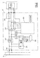
- Figure 1 shows the scheme of an electric lighting upright forming part of the lighting system monitored by the invention.
- Figure 2 shows the circuit block scheme of the transmission unit associated with the upright.
- Figure 3 shows the circuit block diagram of the central control unit.
- The figures show an upright 100i carrying at its end a lamp 10i, where i lies between 1 and n, for a lighting network comprising n uprights.
- The lamp 10i can be either of the mercury vapour type or of the sodium vapour type, in this latter case it being associated with a usual reactor 12i and a suitable ignition system, not shown in the figure.
- The power circuit of each individual lamp 10i can also comprise a rephasing capacitor 13i.
- Within the support upright of each lamp, according to the invention, there is located a transmission unit 2i, the block scheme of which is shown in Figure 2.
- The transmission unit 2i comprises a microprocessor 25i, which in the illustrated example is a Texas Instruments microprocessor type TMS370C6C2 controlling a carrier-wave transmitter-receiver 26i, which in the illustrated example is a National transceiver type LM1893.
- The microprocessor 25i receives data regarding the line and lamp voltage and current, and regarding the power factor associated with the lamp 10i, these data being measured by known devices positioned within the block 23i connected to the lamp feed branch 41i.
- The microprocessor 25i also controls the electromechanical or static relay represented by the block 24i, which switches the lamp 10i in or out.
- The transmitter-receiver represented by the block 26i sends/receives signals to/from the feed line via the
module 21i. - The block 22i represents a carrier-wave blocking filter, the function of which is evident.
- Via the branch 41i and the
line 4 the carrier signals reach thecentral unit 3, the block scheme of which is shown in Figure 3. - The
central unit 3 comprises acentral microprocessor 34, which in the illustrated example is an Intel microprocessor type 80C32, this being able to analyze and compare the data originating from the microprocessors 25i. - The
microprocessor 34 receives data from the carrier-wave transmitter-receiver 33 via themodule 32, which is similar to themodule 21i. - The system operates as follows.
- The
central unit 3 firstly feeds the entire lighting network, with the electromechanical or static relays 24i initially open. - In this situation the voltage present upstream of each electromechanical or static relay 24i in each upright 100i is locally measured by the devices contained in the blocks 23i.
- Comparing the measured voltage with the theoretical or design voltage initially contained in the
microprocessor 34, less load losses, enables operating abnormalities to be detected, such as line discontinuities, dispersions along the line, or unauthorized current withdrawals, also identifying the point along the line where the abnormalities occur. - If the
microprocessor 34 of the central unit encounters no abnormality, it feeds a signal to all the local microprocessors 25i, which close the respective electromechanical or static relays 24i , to cause the lamps to light simultaneously. - It is apparent that this facility for line monitoring with the lamps unlit enables this monitoring to be programmed for very short intervals of several times a day, and hence the entire lighting network to be maintained constantly under control, to provide for the necessary repair and maintenance in good time before the moment for evening lighting of the lamps.
- During the period in which the lamps are alight, the
central microprocessor 34 receives data regarding the current absorbed by each lamp and the power factor, from each peripheral microprocessor 25i. - These data are compared with the data considered normal, to provide all the information concerning the regular operation of the lamp and its state of wear.
- In the case of discrepancy the local microprocessor 25i can temporarily or definitively interrupt power to each individual lamp 10i, to prevent its maloperation causing damage to the entire network.
Claims (5)
- A device for monitoring and managing systems having a multiplicity of identical network user items (1i), such as public lighting systems, comprising at each user item a local transmission unit (2i) composed of an element for measuring the feed parameters (23i) of the user item, a local microprocessor (25i) for processing said parameters, a transceiver (26i) coupled to said microprocessor and the feed line (41i) of the user item via a carrier-wave module (21i) and a carrier-wave blocking filter (22i), and a central processor (34) which receives signals from each local microprocessor (25i) via the feed line, processes them and transmits signals to each local microprocessor (25i), characterised in that the measuring element (23i) for the feed parameters of the user item (1i) is a device for measuring the line voltage and current intensity.
- A device as claimed in claim 1, characterised in that the measuring element (23i) for the user item (1i) feed parameters is a device for measuring the current intensity and the voltage at the user item.
- A device as claimed in claim 1, characterised in that each user item (li) is connected to the feed line by an electromechanical or static relay (24i) controlled by the respective local microprocessor.
- A device as claimed in claim 3, characterised in that the electromechanical or static relay (24i) is positioned downstream of the voltage measuring device (23i), to also enable the voltage to be measured when the user item is disconnected.
- A device as claimed in claim 1 characterised in that said monitoring and managing system monitors with the user items (1i) unlit.
Applications Claiming Priority (2)
| Application Number | Priority Date | Filing Date | Title |
|---|---|---|---|
| ITRE970033 | 1997-05-22 | ||
| IT97RE000033A IT1294432B1 (en) | 1997-05-22 | 1997-05-22 | DEVICE FOR THE CONTROL AND MANAGEMENT OF LIGHTING SYSTEMS. |
Publications (3)
| Publication Number | Publication Date |
|---|---|
| EP0880308A2 EP0880308A2 (en) | 1998-11-25 |
| EP0880308A3 EP0880308A3 (en) | 1999-09-22 |
| EP0880308B1 true EP0880308B1 (en) | 2003-09-03 |
Family
ID=11399043
Family Applications (1)
| Application Number | Title | Priority Date | Filing Date |
|---|---|---|---|
| EP98201545A Revoked EP0880308B1 (en) | 1997-05-22 | 1998-05-08 | Device for monitoring and managing lighting systems |
Country Status (5)
| Country | Link |
|---|---|
| EP (1) | EP0880308B1 (en) |
| AT (1) | ATE249136T1 (en) |
| DE (1) | DE69817673T2 (en) |
| ES (1) | ES2206822T3 (en) |
| IT (1) | IT1294432B1 (en) |
Cited By (3)
| Publication number | Priority date | Publication date | Assignee | Title |
|---|---|---|---|---|
| US7761260B2 (en) | 2005-09-12 | 2010-07-20 | Abl Ip Holding Llc | Light management system having networked intelligent luminaire managers with enhanced diagnostics capabilities |
| US7817063B2 (en) | 2005-10-05 | 2010-10-19 | Abl Ip Holding Llc | Method and system for remotely monitoring and controlling field devices with a street lamp elevated mesh network |
| US8140276B2 (en) | 2008-02-27 | 2012-03-20 | Abl Ip Holding Llc | System and method for streetlight monitoring diagnostics |
Families Citing this family (5)
| Publication number | Priority date | Publication date | Assignee | Title |
|---|---|---|---|---|
| GB2403357A (en) * | 2003-06-25 | 2004-12-29 | Lighthouse Data Man Ltd | Monitoring system for public lighting |
| ITRM20040525A1 (en) * | 2004-10-25 | 2005-01-25 | Silvano Varesi | MANAGEMENT AND CONTROL DEVICE FOR THE POWER SUPPLY OF AN ELECTRIC APPLIANCE, IN PARTICULAR OF A GAS LAMP. |
| EP1657967A1 (en) * | 2004-11-12 | 2006-05-17 | Koninklijke KPN N.V. | A filter with a fuse, for use in a lamppost |
| IT1400313B1 (en) * | 2010-05-31 | 2013-05-24 | Umpi R & D S R L | ELECTRONIC EQUIPMENT FOR DISTANCE DETECTION OF FAULTS LOCATED IN DISCHARGE LAMPS AND ITS PROCEDURE |
| CN105515615A (en) * | 2016-01-12 | 2016-04-20 | 浙江共同电子科技有限公司 | Power line carrier communication method |
Family Cites Families (3)
| Publication number | Priority date | Publication date | Assignee | Title |
|---|---|---|---|---|
| GB9104881D0 (en) * | 1991-03-08 | 1991-04-24 | Ind Cybernetics Ltd | Monitoring apparatus and system |
| GB2284952B (en) * | 1993-11-25 | 1997-10-15 | Ampy Automation Digilog | Remote control of lighting |
| DE69528754T2 (en) * | 1995-05-31 | 2003-07-17 | Umpi Elettronica Cattolica | Electronic device for remote detection of malfunctions in lamps |
-
1997
- 1997-05-22 IT IT97RE000033A patent/IT1294432B1/en active IP Right Grant
-
1998
- 1998-05-08 DE DE69817673T patent/DE69817673T2/en not_active Expired - Fee Related
- 1998-05-08 EP EP98201545A patent/EP0880308B1/en not_active Revoked
- 1998-05-08 AT AT98201545T patent/ATE249136T1/en not_active IP Right Cessation
- 1998-05-08 ES ES98201545T patent/ES2206822T3/en not_active Expired - Lifetime
Cited By (6)
| Publication number | Priority date | Publication date | Assignee | Title |
|---|---|---|---|---|
| US7761260B2 (en) | 2005-09-12 | 2010-07-20 | Abl Ip Holding Llc | Light management system having networked intelligent luminaire managers with enhanced diagnostics capabilities |
| US7911359B2 (en) | 2005-09-12 | 2011-03-22 | Abl Ip Holding Llc | Light management system having networked intelligent luminaire managers that support third-party applications |
| US7817063B2 (en) | 2005-10-05 | 2010-10-19 | Abl Ip Holding Llc | Method and system for remotely monitoring and controlling field devices with a street lamp elevated mesh network |
| US8140276B2 (en) | 2008-02-27 | 2012-03-20 | Abl Ip Holding Llc | System and method for streetlight monitoring diagnostics |
| US8442785B2 (en) | 2008-02-27 | 2013-05-14 | Abl Ip Holding Llc | System and method for streetlight monitoring diagnostics |
| US8594976B2 (en) | 2008-02-27 | 2013-11-26 | Abl Ip Holding Llc | System and method for streetlight monitoring diagnostics |
Also Published As
| Publication number | Publication date |
|---|---|
| DE69817673D1 (en) | 2003-10-09 |
| EP0880308A2 (en) | 1998-11-25 |
| DE69817673T2 (en) | 2004-07-08 |
| EP0880308A3 (en) | 1999-09-22 |
| ES2206822T3 (en) | 2004-05-16 |
| ATE249136T1 (en) | 2003-09-15 |
| ITRE970033A1 (en) | 1998-11-22 |
| IT1294432B1 (en) | 1999-03-24 |
Similar Documents
| Publication | Publication Date | Title |
|---|---|---|
| US6204615B1 (en) | Intelligent outdoor lighting control system | |
| US5962991A (en) | Intelligent outdoor lighting control system | |
| US6791284B1 (en) | Intelligent outdoor lighting control system | |
| CN201286030Y (en) | 10kV complicated electricity supply and distribution control system based on PLC | |
| EP0880308B1 (en) | Device for monitoring and managing lighting systems | |
| CN100468473C (en) | Cascade type electric appliance fire alarming and control device | |
| CN205158104U (en) | Landfill gas body generating set monitored control system | |
| JP3892547B2 (en) | Grid-connected distributed power system | |
| CN104635610A (en) | Waste smoke conveying control device and control method thereof | |
| US20040070281A1 (en) | Method and apparatus for isolating a cogeneration system from a utility source | |
| CN109526116A (en) | Wisdom illumination monitoring terminal, system and corresponding monitoring method | |
| CN108710063A (en) | A kind of power circuit detecting system and method based on electric line carrier communication technology | |
| CN201821164U (en) | Automatic intelligent terminal device for distribution network | |
| CN210072434U (en) | Heater centralized control system | |
| RU2237960C2 (en) | Switchgear for power system feeding power consumers of building | |
| CN1114179C (en) | Circuit for monitoring light siganal | |
| CN111968386A (en) | Intelligent photoelectric traffic control system and control method thereof | |
| CN201611775U (en) | Arc light monitoring and protecting device for bus compartment | |
| Harvey et al. | Implementation of a distributed control system for dynamic lane assignment | |
| CA2687316C (en) | Control arrangement and method for power electronic system | |
| CN214481406U (en) | Intelligent mains supply fault power failure monitoring device for fire-fighting illumination | |
| CN215934815U (en) | Photovoltaic system and local manager | |
| CN220019840U (en) | Portable secondary circuit fault detector for diesel generator system | |
| CN213906994U (en) | System for automatically adjusting illumination of highway tunnel | |
| CN219960212U (en) | Intelligent power manager system of Internet of things |
Legal Events
| Date | Code | Title | Description |
|---|---|---|---|
| PUAI | Public reference made under article 153(3) epc to a published international application that has entered the european phase |
Free format text: ORIGINAL CODE: 0009012 |
|
| AK | Designated contracting states |
Kind code of ref document: A2 Designated state(s): AT BE CH DE DK ES FI FR GB GR IT LI NL PT SE |
|
| AX | Request for extension of the european patent |
Free format text: AL;LT;LV;MK;RO;SI |
|
| PUAL | Search report despatched |
Free format text: ORIGINAL CODE: 0009013 |
|
| AK | Designated contracting states |
Kind code of ref document: A3 Designated state(s): AT BE CH CY DE DK ES FI FR GB GR IE IT LI LU MC NL PT SE |
|
| AX | Request for extension of the european patent |
Free format text: AL;LT;LV;MK;RO;SI |
|
| 17P | Request for examination filed |
Effective date: 20000313 |
|
| AKX | Designation fees paid |
Free format text: AT BE CH DE DK ES FI FR GB GR IT LI NL PT SE |
|
| AXX | Extension fees paid |
Free format text: RO PAYMENT 20000313 |
|
| RAP1 | Party data changed (applicant data changed or rights of an application transferred) |
Owner name: ELETTRONICA REVERBERI S.R.L. |
|
| RIN1 | Information on inventor provided before grant (corrected) |
Inventor name: ELETTRONICA REVERBERI S.R.L. |
|
| GRAH | Despatch of communication of intention to grant a patent |
Free format text: ORIGINAL CODE: EPIDOS IGRA |
|
| GRAH | Despatch of communication of intention to grant a patent |
Free format text: ORIGINAL CODE: EPIDOS IGRA |
|
| 17Q | First examination report despatched |
Effective date: 20030414 |
|
| GRAA | (expected) grant |
Free format text: ORIGINAL CODE: 0009210 |
|
| AK | Designated contracting states |
Kind code of ref document: B1 Designated state(s): AT BE CH DE DK ES FI FR GB GR IT LI NL PT SE |
|
| AX | Request for extension of the european patent |
Extension state: RO |
|
| PG25 | Lapsed in a contracting state [announced via postgrant information from national office to epo] |
Ref country code: NL Free format text: LAPSE BECAUSE OF FAILURE TO SUBMIT A TRANSLATION OF THE DESCRIPTION OR TO PAY THE FEE WITHIN THE PRESCRIBED TIME-LIMIT Effective date: 20030903 Ref country code: LI Free format text: LAPSE BECAUSE OF FAILURE TO SUBMIT A TRANSLATION OF THE DESCRIPTION OR TO PAY THE FEE WITHIN THE PRESCRIBED TIME-LIMIT Effective date: 20030903 Ref country code: IT Free format text: LAPSE BECAUSE OF FAILURE TO SUBMIT A TRANSLATION OF THE DESCRIPTION OR TO PAY THE FEE WITHIN THE PRESCRIBED TIME-LIMIT;WARNING: LAPSES OF ITALIAN PATENTS WITH EFFECTIVE DATE BEFORE 2007 MAY HAVE OCCURRED AT ANY TIME BEFORE 2007. THE CORRECT EFFECTIVE DATE MAY BE DIFFERENT FROM THE ONE RECORDED. Effective date: 20030903 Ref country code: FI Free format text: LAPSE BECAUSE OF FAILURE TO SUBMIT A TRANSLATION OF THE DESCRIPTION OR TO PAY THE FEE WITHIN THE PRESCRIBED TIME-LIMIT Effective date: 20030903 Ref country code: CH Free format text: LAPSE BECAUSE OF FAILURE TO SUBMIT A TRANSLATION OF THE DESCRIPTION OR TO PAY THE FEE WITHIN THE PRESCRIBED TIME-LIMIT Effective date: 20030903 Ref country code: BE Free format text: LAPSE BECAUSE OF FAILURE TO SUBMIT A TRANSLATION OF THE DESCRIPTION OR TO PAY THE FEE WITHIN THE PRESCRIBED TIME-LIMIT Effective date: 20030903 Ref country code: AT Free format text: LAPSE BECAUSE OF FAILURE TO SUBMIT A TRANSLATION OF THE DESCRIPTION OR TO PAY THE FEE WITHIN THE PRESCRIBED TIME-LIMIT Effective date: 20030903 |
|
| REG | Reference to a national code |
Ref country code: GB Ref legal event code: FG4D |
|
| REG | Reference to a national code |
Ref country code: CH Ref legal event code: EP |
|
| REF | Corresponds to: |
Ref document number: 69817673 Country of ref document: DE Date of ref document: 20031009 Kind code of ref document: P |
|
| PG25 | Lapsed in a contracting state [announced via postgrant information from national office to epo] |
Ref country code: SE Free format text: LAPSE BECAUSE OF FAILURE TO SUBMIT A TRANSLATION OF THE DESCRIPTION OR TO PAY THE FEE WITHIN THE PRESCRIBED TIME-LIMIT Effective date: 20031203 Ref country code: GR Free format text: LAPSE BECAUSE OF FAILURE TO SUBMIT A TRANSLATION OF THE DESCRIPTION OR TO PAY THE FEE WITHIN THE PRESCRIBED TIME-LIMIT Effective date: 20031203 Ref country code: DK Free format text: LAPSE BECAUSE OF FAILURE TO SUBMIT A TRANSLATION OF THE DESCRIPTION OR TO PAY THE FEE WITHIN THE PRESCRIBED TIME-LIMIT Effective date: 20031203 |
|
| NLV1 | Nl: lapsed or annulled due to failure to fulfill the requirements of art. 29p and 29m of the patents act | ||
| PG25 | Lapsed in a contracting state [announced via postgrant information from national office to epo] |
Ref country code: PT Free format text: LAPSE BECAUSE OF FAILURE TO SUBMIT A TRANSLATION OF THE DESCRIPTION OR TO PAY THE FEE WITHIN THE PRESCRIBED TIME-LIMIT Effective date: 20040203 |
|
| REG | Reference to a national code |
Ref country code: CH Ref legal event code: PL |
|
| PG25 | Lapsed in a contracting state [announced via postgrant information from national office to epo] |
Ref country code: GB Free format text: LAPSE BECAUSE OF NON-PAYMENT OF DUE FEES Effective date: 20040508 |
|
| REG | Reference to a national code |
Ref country code: ES Ref legal event code: FG2A Ref document number: 2206822 Country of ref document: ES Kind code of ref document: T3 |
|
| PGFP | Annual fee paid to national office [announced via postgrant information from national office to epo] |
Ref country code: ES Payment date: 20040520 Year of fee payment: 7 |
|
| PLBQ | Unpublished change to opponent data |
Free format text: ORIGINAL CODE: EPIDOS OPPO |
|
| PGFP | Annual fee paid to national office [announced via postgrant information from national office to epo] |
Ref country code: FR Payment date: 20040524 Year of fee payment: 7 |
|
| PLBI | Opposition filed |
Free format text: ORIGINAL CODE: 0009260 |
|
| PGFP | Annual fee paid to national office [announced via postgrant information from national office to epo] |
Ref country code: DE Payment date: 20040608 Year of fee payment: 7 |
|
| ET | Fr: translation filed | ||
| PLAX | Notice of opposition and request to file observation + time limit sent |
Free format text: ORIGINAL CODE: EPIDOSNOBS2 |
|
| 26 | Opposition filed |
Opponent name: IM.EL. S.N.C.IMPIANTI ELETTRICI DI BIGAZZI MAURO Effective date: 20040511 |
|
| GBPC | Gb: european patent ceased through non-payment of renewal fee |
Effective date: 20040508 |
|
| RDAF | Communication despatched that patent is revoked |
Free format text: ORIGINAL CODE: EPIDOSNREV1 |
|
| RDAG | Patent revoked |
Free format text: ORIGINAL CODE: 0009271 |
|
| STAA | Information on the status of an ep patent application or granted ep patent |
Free format text: STATUS: PATENT REVOKED |
|
| 27W | Patent revoked |
Effective date: 20050819 |