EP0877636B1 - Dilatation catheter balloons with improved puncture resistance - Google Patents
Dilatation catheter balloons with improved puncture resistance Download PDFInfo
- Publication number
- EP0877636B1 EP0877636B1 EP97904880A EP97904880A EP0877636B1 EP 0877636 B1 EP0877636 B1 EP 0877636B1 EP 97904880 A EP97904880 A EP 97904880A EP 97904880 A EP97904880 A EP 97904880A EP 0877636 B1 EP0877636 B1 EP 0877636B1
- Authority
- EP
- European Patent Office
- Prior art keywords
- layer
- thickness
- micrometers
- catheter balloon
- dilatation catheter
- Prior art date
- Legal status (The legal status is an assumption and is not a legal conclusion. Google has not performed a legal analysis and makes no representation as to the accuracy of the status listed.)
- Expired - Lifetime
Links
Images
Classifications
-
- B—PERFORMING OPERATIONS; TRANSPORTING
- B32—LAYERED PRODUCTS
- B32B—LAYERED PRODUCTS, i.e. PRODUCTS BUILT-UP OF STRATA OF FLAT OR NON-FLAT, e.g. CELLULAR OR HONEYCOMB, FORM
- B32B27/00—Layered products comprising a layer of synthetic resin
- B32B27/06—Layered products comprising a layer of synthetic resin as the main or only constituent of a layer, which is next to another layer of the same or of a different material
- B32B27/08—Layered products comprising a layer of synthetic resin as the main or only constituent of a layer, which is next to another layer of the same or of a different material of synthetic resin
-
- A—HUMAN NECESSITIES
- A61—MEDICAL OR VETERINARY SCIENCE; HYGIENE
- A61L—METHODS OR APPARATUS FOR STERILISING MATERIALS OR OBJECTS IN GENERAL; DISINFECTION, STERILISATION OR DEODORISATION OF AIR; CHEMICAL ASPECTS OF BANDAGES, DRESSINGS, ABSORBENT PADS OR SURGICAL ARTICLES; MATERIALS FOR BANDAGES, DRESSINGS, ABSORBENT PADS OR SURGICAL ARTICLES
- A61L29/00—Materials for catheters, medical tubing, cannulae, or endoscopes or for coating catheters
- A61L29/04—Macromolecular materials
- A61L29/041—Macromolecular materials obtained by reactions only involving carbon-to-carbon unsaturated bonds
-
- A—HUMAN NECESSITIES
- A61—MEDICAL OR VETERINARY SCIENCE; HYGIENE
- A61L—METHODS OR APPARATUS FOR STERILISING MATERIALS OR OBJECTS IN GENERAL; DISINFECTION, STERILISATION OR DEODORISATION OF AIR; CHEMICAL ASPECTS OF BANDAGES, DRESSINGS, ABSORBENT PADS OR SURGICAL ARTICLES; MATERIALS FOR BANDAGES, DRESSINGS, ABSORBENT PADS OR SURGICAL ARTICLES
- A61L29/00—Materials for catheters, medical tubing, cannulae, or endoscopes or for coating catheters
- A61L29/04—Macromolecular materials
- A61L29/049—Mixtures of macromolecular compounds
-
- A—HUMAN NECESSITIES
- A61—MEDICAL OR VETERINARY SCIENCE; HYGIENE
- A61L—METHODS OR APPARATUS FOR STERILISING MATERIALS OR OBJECTS IN GENERAL; DISINFECTION, STERILISATION OR DEODORISATION OF AIR; CHEMICAL ASPECTS OF BANDAGES, DRESSINGS, ABSORBENT PADS OR SURGICAL ARTICLES; MATERIALS FOR BANDAGES, DRESSINGS, ABSORBENT PADS OR SURGICAL ARTICLES
- A61L29/00—Materials for catheters, medical tubing, cannulae, or endoscopes or for coating catheters
- A61L29/04—Macromolecular materials
- A61L29/06—Macromolecular materials obtained otherwise than by reactions only involving carbon-to-carbon unsaturated bonds
-
- A—HUMAN NECESSITIES
- A61—MEDICAL OR VETERINARY SCIENCE; HYGIENE
- A61L—METHODS OR APPARATUS FOR STERILISING MATERIALS OR OBJECTS IN GENERAL; DISINFECTION, STERILISATION OR DEODORISATION OF AIR; CHEMICAL ASPECTS OF BANDAGES, DRESSINGS, ABSORBENT PADS OR SURGICAL ARTICLES; MATERIALS FOR BANDAGES, DRESSINGS, ABSORBENT PADS OR SURGICAL ARTICLES
- A61L29/00—Materials for catheters, medical tubing, cannulae, or endoscopes or for coating catheters
- A61L29/08—Materials for coatings
- A61L29/085—Macromolecular materials
-
- A—HUMAN NECESSITIES
- A61—MEDICAL OR VETERINARY SCIENCE; HYGIENE
- A61M—DEVICES FOR INTRODUCING MEDIA INTO, OR ONTO, THE BODY; DEVICES FOR TRANSDUCING BODY MEDIA OR FOR TAKING MEDIA FROM THE BODY; DEVICES FOR PRODUCING OR ENDING SLEEP OR STUPOR
- A61M25/00—Catheters; Hollow probes
- A61M25/10—Balloon catheters
- A61M25/1027—Making of balloon catheters
- A61M25/1029—Production methods of the balloon members, e.g. blow-moulding, extruding, deposition or by wrapping a plurality of layers of balloon material around a mandril
-
- B—PERFORMING OPERATIONS; TRANSPORTING
- B32—LAYERED PRODUCTS
- B32B—LAYERED PRODUCTS, i.e. PRODUCTS BUILT-UP OF STRATA OF FLAT OR NON-FLAT, e.g. CELLULAR OR HONEYCOMB, FORM
- B32B1/00—Layered products having a general shape other than plane
- B32B1/08—Tubular products
-
- B—PERFORMING OPERATIONS; TRANSPORTING
- B32—LAYERED PRODUCTS
- B32B—LAYERED PRODUCTS, i.e. PRODUCTS BUILT-UP OF STRATA OF FLAT OR NON-FLAT, e.g. CELLULAR OR HONEYCOMB, FORM
- B32B27/00—Layered products comprising a layer of synthetic resin
- B32B27/28—Layered products comprising a layer of synthetic resin comprising synthetic resins not wholly covered by any one of the sub-groups B32B27/30 - B32B27/42
- B32B27/285—Layered products comprising a layer of synthetic resin comprising synthetic resins not wholly covered by any one of the sub-groups B32B27/30 - B32B27/42 comprising polyethers
-
- B—PERFORMING OPERATIONS; TRANSPORTING
- B32—LAYERED PRODUCTS
- B32B—LAYERED PRODUCTS, i.e. PRODUCTS BUILT-UP OF STRATA OF FLAT OR NON-FLAT, e.g. CELLULAR OR HONEYCOMB, FORM
- B32B27/00—Layered products comprising a layer of synthetic resin
- B32B27/32—Layered products comprising a layer of synthetic resin comprising polyolefins
-
- B—PERFORMING OPERATIONS; TRANSPORTING
- B32—LAYERED PRODUCTS
- B32B—LAYERED PRODUCTS, i.e. PRODUCTS BUILT-UP OF STRATA OF FLAT OR NON-FLAT, e.g. CELLULAR OR HONEYCOMB, FORM
- B32B27/00—Layered products comprising a layer of synthetic resin
- B32B27/34—Layered products comprising a layer of synthetic resin comprising polyamides
-
- B—PERFORMING OPERATIONS; TRANSPORTING
- B32—LAYERED PRODUCTS
- B32B—LAYERED PRODUCTS, i.e. PRODUCTS BUILT-UP OF STRATA OF FLAT OR NON-FLAT, e.g. CELLULAR OR HONEYCOMB, FORM
- B32B27/00—Layered products comprising a layer of synthetic resin
- B32B27/36—Layered products comprising a layer of synthetic resin comprising polyesters
-
- B—PERFORMING OPERATIONS; TRANSPORTING
- B32—LAYERED PRODUCTS
- B32B—LAYERED PRODUCTS, i.e. PRODUCTS BUILT-UP OF STRATA OF FLAT OR NON-FLAT, e.g. CELLULAR OR HONEYCOMB, FORM
- B32B27/00—Layered products comprising a layer of synthetic resin
- B32B27/40—Layered products comprising a layer of synthetic resin comprising polyurethanes
-
- A—HUMAN NECESSITIES
- A61—MEDICAL OR VETERINARY SCIENCE; HYGIENE
- A61M—DEVICES FOR INTRODUCING MEDIA INTO, OR ONTO, THE BODY; DEVICES FOR TRANSDUCING BODY MEDIA OR FOR TAKING MEDIA FROM THE BODY; DEVICES FOR PRODUCING OR ENDING SLEEP OR STUPOR
- A61M25/00—Catheters; Hollow probes
- A61M25/10—Balloon catheters
- A61M25/104—Balloon catheters used for angioplasty
-
- B—PERFORMING OPERATIONS; TRANSPORTING
- B29—WORKING OF PLASTICS; WORKING OF SUBSTANCES IN A PLASTIC STATE IN GENERAL
- B29C—SHAPING OR JOINING OF PLASTICS; SHAPING OF MATERIAL IN A PLASTIC STATE, NOT OTHERWISE PROVIDED FOR; AFTER-TREATMENT OF THE SHAPED PRODUCTS, e.g. REPAIRING
- B29C55/00—Shaping by stretching, e.g. drawing through a die; Apparatus therefor
-
- B—PERFORMING OPERATIONS; TRANSPORTING
- B32—LAYERED PRODUCTS
- B32B—LAYERED PRODUCTS, i.e. PRODUCTS BUILT-UP OF STRATA OF FLAT OR NON-FLAT, e.g. CELLULAR OR HONEYCOMB, FORM
- B32B2307/00—Properties of the layers or laminate
- B32B2307/50—Properties of the layers or laminate having particular mechanical properties
- B32B2307/514—Oriented
- B32B2307/518—Oriented bi-axially
-
- B—PERFORMING OPERATIONS; TRANSPORTING
- B32—LAYERED PRODUCTS
- B32B—LAYERED PRODUCTS, i.e. PRODUCTS BUILT-UP OF STRATA OF FLAT OR NON-FLAT, e.g. CELLULAR OR HONEYCOMB, FORM
- B32B2367/00—Polyesters, e.g. PET, i.e. polyethylene terephthalate
-
- B—PERFORMING OPERATIONS; TRANSPORTING
- B32—LAYERED PRODUCTS
- B32B—LAYERED PRODUCTS, i.e. PRODUCTS BUILT-UP OF STRATA OF FLAT OR NON-FLAT, e.g. CELLULAR OR HONEYCOMB, FORM
- B32B2371/00—Polyethers, e.g. PEEK, i.e. polyether-etherketone; PEK, i.e. polyetherketone
-
- B—PERFORMING OPERATIONS; TRANSPORTING
- B32—LAYERED PRODUCTS
- B32B—LAYERED PRODUCTS, i.e. PRODUCTS BUILT-UP OF STRATA OF FLAT OR NON-FLAT, e.g. CELLULAR OR HONEYCOMB, FORM
- B32B2375/00—Polyureas; Polyurethanes
-
- B—PERFORMING OPERATIONS; TRANSPORTING
- B32—LAYERED PRODUCTS
- B32B—LAYERED PRODUCTS, i.e. PRODUCTS BUILT-UP OF STRATA OF FLAT OR NON-FLAT, e.g. CELLULAR OR HONEYCOMB, FORM
- B32B2377/00—Polyamides
-
- B—PERFORMING OPERATIONS; TRANSPORTING
- B32—LAYERED PRODUCTS
- B32B—LAYERED PRODUCTS, i.e. PRODUCTS BUILT-UP OF STRATA OF FLAT OR NON-FLAT, e.g. CELLULAR OR HONEYCOMB, FORM
- B32B2535/00—Medical equipment, e.g. bandage, prostheses, catheter
-
- Y—GENERAL TAGGING OF NEW TECHNOLOGICAL DEVELOPMENTS; GENERAL TAGGING OF CROSS-SECTIONAL TECHNOLOGIES SPANNING OVER SEVERAL SECTIONS OF THE IPC; TECHNICAL SUBJECTS COVERED BY FORMER USPC CROSS-REFERENCE ART COLLECTIONS [XRACs] AND DIGESTS
- Y10—TECHNICAL SUBJECTS COVERED BY FORMER USPC
- Y10T—TECHNICAL SUBJECTS COVERED BY FORMER US CLASSIFICATION
- Y10T428/00—Stock material or miscellaneous articles
- Y10T428/13—Hollow or container type article [e.g., tube, vase, etc.]
- Y10T428/1352—Polymer or resin containing [i.e., natural or synthetic]
Definitions
- This invention relates to dilatation catheter balloons suitable for use in percutaneous transluminal coronary angioplasty. More particularly, this invention relates to such balloons exhibiting improved puncture resistance.
- Dilatation catheter balloons are used in invasive medical procedures such as percutaneous transluminal coronary angioplasty (PTCA). This particular procedure has become a tool of major importance in the treatment of coronary heart disease, as described by D. S. Baim, MD, in Heart Disease. A Textbook of Cardiovascular Medicine. 4th Edition, Chapter 41, E. Braunwald, Ed, published by W. B. Saunders Company, 1992.
- PTCA percutaneous transluminal coronary angioplasty
- U.S. 4,490,421 discloses high strength, high modulus biaxially oriented articles exhibiting a preferred mode of failure, the process being particularly well-suited for the production of dilatation catheter balloons for invasive medical procedures, as taught therein.
- stents intraluminal prostheses known as stents are placed in the treated vessel to serve as a reinforcing member, and prevent the further accretion of materials at the location of the original lesion. Stents are for the most part made from metal wires or tubes.
- a preferred method for implantation of the stent is to place the stent around the outside of a balloon catheter. As the balloon is expanded to treat the lesion, the stent is simultaneously expanded. The balloon is subsequently deflated and withdrawn, leaving the stent in place.
- the balloon is undesirably susceptible to puncture by the sharp edges of the stent during the expansion and implantation phase of treatment.
- a puncture so caused then induces a failure in the balloon, forcing the procedure to be aborted, thus subjecting the patient to unnecessary risk and adding undesirably to the cost of the procedure
- 5,290,306 discloses the use of a thermoplastic elastomer, of a hardness less than 55 D according to ASTM D2240, preferably a polyurethane, as the outer layer in a biaxially oriented coextruded tubular article wherein the inner layer is PET or polyamide.
- U.S. 5,195,969 discloses a biaxially oriented coextruded tubular article consisting of an inner layer of PET film and an outer layer of a so-called toughened blend of PET. These articles are said to exhibit improved puncture resistance.
- WO 95/09667 discloses catheter balloon compositions encompassing HYTREL polymers having flexural moduli in the range of 21,000-440,000 psi in combination with PET in the compositional range of 40:60-60:40 in a single layer balloon .
- US-A-5290306 discloses a balloon catheter, which comprises a flexible, elongated member, an inflatable balloon carried on the elongated member to define an inflation chamber within said balloon, and an inflation conduit extending along said member and communicating with the inflation chamber, said inflatable balloon being surrounded by an elastomeric sleeve to provide pinhole and abrasion resistance to said balloon, said balloon and sleeve being together defined by a coextruded tube, said balloon being made of a flexible, relatively inelastic, biaxially oriented material selected from the group consisting of PET and nylon.
- the present invention provides a puncture-resistant dilatation catheter balloon suitable for use in PTCA accompanied by the implantation of vascular stents, and in other medical dilatation procedures.
- the present invention provides for a dilatation catheter balloon suitable for use in PTCA, comprising a first, inner layer comprising at least 80% by weight of a biaxially oriented thermoplastic resin selected from the group consisting of polyesters, polyamides, polyolefins, and blends thereof, and up to 20% by weight of a thermoplastic elastomer selected from the group consisting of polyurethanes, polyether-ester block copolymers, the first, inner layer having an inside surface and an outside surface and a thickness of 5-56 micrometers.
- Another embodiment of the present invention provides for a third layer comprising at least 80% by weight of a biaxially oriented thermoplastic resin selected from the group consisting of polyesters, polyamides, polyolefins, and blends thereof, and up to 20% by weight of a thermoplastic elastomer selected from the group consisting of polyurethanes, polyether-ester block copolymers.
- a biaxially oriented thermoplastic resin selected from the group consisting of polyesters, polyamides, polyolefins, and blends thereof, and up to 20% by weight of a thermoplastic elastomer selected from the group consisting of polyurethanes, polyether-ester block copolymers.
- This layer has an inside surface and an outside surface and a thickness of 1-5 micrometers; the inside surface thereof is secured to the outside surface of the second layer.
- other layers as disclosed herein may be applied as desired concurrently with or subsequent to the fabrication of the multi-layer catheter balloon of this invention.
- the biaxially oriented thermoplastic resin is polyethylene terephthalate.
- the thermoplastic elastomer is desirably a polyetherester block copolymer.
- the dilatation catheter balloons described herein may be prepared according to the process of the present invention.
- the process comprises forming a tube comprising a first inner layer, a second layer, and optionally a third layer. Each layer has both inside and outside surfaces; the layers are arranged such that the inside surface of the second layer is secured to the outside surface of the first inner layer, and the inside surface of the third layer is secured to the outside surface of the second layer.
- the first inner layer comprises at least 80% by weight of a biaxially orientable thermoplastic resin as disclosed hereinabove and up to 20% by weight of a thermoplastic elastomer as disclosed hereinabove. It has a thickness of 5-56 micrometers.
- the second layer is a thermoplastic ionomeric olefin copolymer having a thickness of 0.5-5 micrometers.
- the optional third layer is selected from the materials of the first inner layer. The layers are fused concurrently or consecutively with formation of the tube. The tube is quenched and biaxially oriented to produce a dilatation catheter balloon. The catheter balloon is heat set.
- Thermoplastic ionomeric olefin copolymers offer several improvements over the known art.
- thermoplastic elastomers most specifically the polyurethane of the art, ionomers are less costly, crystallize more quickly permitting quicker molding cycle times. and are less subject to thermal degradation when briefly exposed to high temperatures.
- toughened PET blends ionomers are less costly and tougher.
- ionomers are also known as excellent heat sealing agents, and thus incorporation of the ionomer into, e.g., a catheter balloon affords improved structural integrity of the assembly without resort to adhesives.
- PET and an ionomeric olefin copolymer are combined in a biaxially oriented two-layer catheter balloon wherein the outer layer is the ionomeric olefin copolymer.
- the PET is preferably of an intrinsic viscosity in the range of 0.5-1.1, most preferably in the range of 0.8-1.1.
- the thermoplastic ionomeric olefin copolymer is preferably of a melt index (MI) of less than 5 according to ASTM D-1238, a flexural modulus of less than about 250 MPa according to ASTM D-790, most preferably about 100 MPa.
- bursting can be caused either by a tensile failure of the balloon under the stress of the pressure of the inflating fluid, or by puncture, as hereinabove discussed.
- Tensile strength of the balloon can be maximized for given materials of construction by increasing the thickness of the strength member. That is, the inner layer must be as thick as possible.
- the toughening or puncture-resistant layer which is the ionomeric olefin copolymer layer, must be sufficiently thick to provide sufficient protection against puncture.
- the thickness of the first, inner layer is 5-56 micrometers, preferably 9-27 micrometers, most preferably 11-19 micrometers.
- the thickness of the second, outer ionomer layer is 0.5-5 micrometers, preferably 0.6-2 micrometers, most preferably 0.8-1 micrometers.
- the two layer oriented article of the present invention is disposed whereby the ionomer layer is presented to the potential source of puncture.
- the ionomer layer resides on the outside of the balloon, and is the first upon which, as the balloon is inflated, is impinged the stent.
- a third polymeric film layer selected from the same group as the first layer, is coextruded with the first two, such that the second, ionomeric layer is sandwiched between the two, the third layer being contiguous with and outwardly disposed upon the ionomeric layer.
- the third layer is preferably 1-5 micrometers in thickness, most preferably 2-4 micrometers. It is found in the practice of this invention that the thin third layer, preferably of PET, provides excellent mold-release with no need to resort to any additional measures to secure that release.
- the three-layered oriented catheter balloons of this invention provide significant improvements in puncture resistance with respect to otherwise comparable two-layered catheter balloons.
- the puncture resistance was improved by 50-200% over that obtained from the two layer film, and over that obtained by presenting the first, or thicker, layer of the three layer film, to the puncture source.
- each resin or resin blend to be used is charged in the form of pellets or powder, preferably pellets, to a separate extruder wherein it is melted and fed in the melt to a multi-layer combining feed block adaptor whence it is fed to a tubular die, wherein the layers are formed and extruded.
- the thickness ratio of the layers is determined by the respective flow rates of the different melt streams, these being determined primarily by adjusting the extruder screw speeds as appropriate for obtaining the desired result.
- PET resin of an intrinsic viscosity in the range of 0.55 to 1.1 is coextruded with a thermoplastic ionomeric olefin copolymer preferred for the practice of this invention.
- the PET extruder is preferably operated at ca. 275°C, while the olefin ionomer extruder is operated at ca. 200°C.
- the molten outputs of the extruders are fed to a combining feed block in which the two melts are combined just prior to passing through the extrusion die. In order to keep the PET molten, the block and die must be kept at ca.
- the residence time of the ionomer in the block and die must be kept to less than 10 minutes, preferably less than 5 minutes. Residence time can be adjusted by adjusting extruder screw speeds, die gaps, and take-off rates.
- a two or three layer film is coextruded into tube which is quenched by immersing the tubing in a water bath maintained at ca. 40°C, followed by orientation as described in Levy.
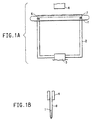
- a fine tooth saw blade 1 ("Greenstripe" type SF1218 manufactured by L. S. Starrett Co., Athol, MA) was mounted on the top member of a stainless steel frame 2 3.18 mm in thickness, with inner dimensions of 127 x 127 mm, by fasteners 6 and 7 so that the saw teeth extended 3.8 mm beyond the inside edge of the frame 2.
- the bottom member of the frame 2 was clamped by lower clamp 3 in the lower jaw (not shown) of a Tensile Testing Machine model 2W manufactured by Systems Integration Technology, Inc., Staughton, MA.
- the position of the upper jaw (not shown) of the machine was adjusted so that the edge of the saw blade 1 was 38 mm below the jaw.
- a film specimen 8 of dimensions 127 mm long and 25.4 mm wide was looped through the frame 2 and the two ends of the film specimen 8 secured in the upper clamp 4 of the testing machine so that the middle of the film specimen 8 was in contact with the teeth of the saw blade 1.
- the jaws were then separated at a rate of 50.8 mm/sec and the applied force and time to failure were determined, and the energy to break was determined therefrom.
- Instrinsic Viscosity was determined using the method of ASTM D5225-92 except that the solvent employed was a 50/50 mixture of trichloroacetic acid and methylene chloride.
- a linear high molecular weight PET homopolymer sold under the trademark SELAR PT X280, available from E. I. du Pont de Nemours and Company, and having an IV of 1.1 was extruded using a 25.4 mm single screw extruder, available from Killion, Inc., Vernon, NJ, and a 15.2 cm wide coat hanger film die with the die opening set at 0.51 mm. Films were extruded at 116 cm/min at a screw speed of 40 rpm and extruder temperature at 280°C. The extruded film was ca. 0.24 mm thick. Nine film specimens were oriented biaxially 250% in each direction, and heat set. The resulting films ranged in thickness from 0.016 mm to 0.022 mm and exhibited an average normalized energy to break of (0,534 ⁇ 0,01)* 10 -3 J/ ⁇ m (0.12 ⁇ 0.02 in-lb/mil).
- SURLYN is the trademark of an ionomeric resin made from a copolymer of ethylene and methacrylic acid, neutralized with either zinc or sodium to form the ionomer and available from E. I. du Pont de Nemours and Company.
- SURLYN 9020 is a zinc ionomer with a Melt Index (ASTM D-1238) of 1.1.
- SURLYN 9721 is a zinc monomer with a Melt Index of 1.0.
- SURLYN 8020 is a sodium ionomer with a Melt Index of 1.0.
- HYTREL 4056 is the trademark for a low modulus, extrusion grade block copolyetherester thermoplastic elastomer characterized by a Shore hardness of 40 D (ASTM D-2240), and available from E. I. du Pont de Nemours and Company.
- the SELAR PT X280 was extruded through a 3.81 cm single screw extruder, available from Killion, Inc., Vernon, NJ, at 32 rpm and ca. 275°C.
- the SURLYN and HYTREL 4056 resins of Table 1 were extruded through a 3.18 single screw Killion extruder operating at 5 rpm and a temperature of 200°C the molten output of the two extruders was directed through a two-layer combining feed block, adaptor with a 35.6 cm wide slot die having a 0.38 mm die gap.
- the feed block and die were maintained at ca. 265°C.
- the samples so produced were quenched, oriented and heat set as hereinabove specified, and are described in Table 1. In all cases, the PET layer of the bilayer film was in contact with the 60°C quench drum.
- the layers were delaminated by affixing a piece of pressure sensitive adhesive tape to the two sides of the film and then pulling them apart.
- the SELAR PT X280/HYTREL laminates could not be separated in that manner.
- the film of Comparative Example 2 was a film of the art of Trotta et al. (U.S. 5,290,306). Table 2 lists the results obtained from the puncture test hereinabove described. In each case, layer 2 was in initial contact with the saw blade. Each datum represents an average of three determinations. Description of Two-Laver Films Layer 1 Layer 2 Resin Thickness ( ⁇ m) Resin Thickness ( ⁇ m) Example 1 SELAR PT X280 24.1 SURLYN 9020 1.3 Example 2 SELAR PT X280 26.7 SURLYN 9721 1.3 Example 3 SELAR PT X280 29.2 SURLYN 8020 2.5 Comp. Ex.
- Three-layer biaxial films were prepared by simultaneously extruding two layers of SELAR PT X280 on either side of a layer of the resins indicated in Table 3.
- the SELAR PT X280 was extruded as in Examples 1-3 except that the screw speed was 38 rpm.
- the middle layer resins were extruded through the 2.54 cm single screw extruder of Comparative Example 1, operated in the range of 6-14 rpm, and at a temperature of ca. 220°C.
- the extruder outputs were fed to a three-layer combining feed block adapter and a 35.6 cm wide slot die having a 0.38 mm die gap to obtain a film of ca. 0.24 mm thickness.
- Example 8 Additional specimens of oriented, heat set film of the extruded film of Example 8 were prepared as hereinabove described. They were oriented biaxially 225% in each direction. The films are described in Table 5. Rupture resistance was determined for Example 11 with Layer 3 in contact with the saw blade, as in Example 8. Those for Examples 12 and 13 with Layer 1 in contact with the saw blade. Results are shown in Table 6.
- Example 14 SELAR PT X280 was extruded into a single layer film using a 28 mm co-rotating, twin screw extruder manufactured by Werner and Pfleiderer, Inc., Ramsey, NJ. Screw speed was 100 rpm. Temperatures, quenching and orientation were as stated hereinabove.
- du Pont de Nemours and Company was extruded in a single-layer film under the same conditions as those for Comparative Example 3. Both were oriented as hereinabove described, biaxially 250% in each direction.
- the SELAR PT X280 film had a thickness of 17 micrometers and the blend film had a thickness of 16 micrometers.
- the film of Comparative Example 3 exhibited a normalized energy to break of 0,712 x 10 -3 J/ ⁇ m (0.16 in-lb/mil) (33% higher than that of Comparative Example 1), while the film of Example 14 exhibited a normalized energy to break of 1.068 x 10 -3 J/ ⁇ m (0.24 in-lb/mil), or an improvement of 50% over that of Comparative Example 3.
- Three-layer biaxially oriented heat set films were prepared by coextruding, orienting and heat setting a blend comprising 85% SELAR PT X280 and 15% HYTREL 8238 with SURLYN 9020 and HYTREL 4056 in the manner described in Examples 4-10.
- the films are described in Table 7. In each case, Layer 3 (the thick layer) was presented to the saw blade. Table 8 shows the results.
- Two layer tubing was made by simultaneously extruding a high molecular weight, linear PET homopolymer sold under the trademark SELAR PT 7451, available from E. I. du Pont de Nemours and Company and having an IV of 0.95 as an inner layer and SURLYN 8020 as an outer layer through a Canterbury Engineering Co. tri-layer tubing die by idling one of the layer positions.
- SELAR PT 7451 was extruded with a 2.54 cm single-screw Killion extruder maintained at 275°C and a screw speed of 12 rpm.
- the SURLYN 8020 was extruded with a 1.91 cm extruder, manufactured by Genca, Clearwater FL, maintained at 210°C and a screw speed of 17 rpm.
- the tri-layered die was maintained at 280°C.
- the 0.8 mm (outside diameter), 0.36 mm inside diameter tube was produced at a rate of 32.6 m/min.
- the polymer flow rates through the die were adjusted by valves to obtain a SELAR PT 7451 layer thickness of 0.14 mm and a SURLYN 8020 ionomer layer thickness of 0.04 mm.
- Example 11-13 The film of Examples 11-13 was prepared into two specimens. In the first, that of Example 18, the thick layer of SELAR PT X280 (layer 3) was stripped off the remaining two layers, thus exposing a layer of SURLYN 9020. In Example 19, the 3 layer film was left intact.
- the specimens thus prepared were individually placed between sheets of aluminum foil, the assembly resulting therefrom being placed between the heated platens of a model 2699 Carver Laboratory Press, manufactured by Fred S. Carver, In, Menomonee Falls WI, and subject to 3,445 x 10 6 Pa (500 psi) ram pressure and temperature for 1 minute, as described in Table 9. After pressing, an effort was made to remove the specimens from the aluminum sheets. Observations are given in Table 9.
Abstract
Description
| Description of Two-Laver Films | ||||
| Layer 1 | | |||
| Resin | Thickness (µm) | Resin | Thickness (µm) | |
| Example 1 | SELAR PT X280 | 24.1 | SURLYN 9020 | 1.3 |
| Example 2 | SELAR PT X280 | 26.7 | SURLYN 9721 | 1.3 |
| Example 3 | SELAR PT X280 | 29.2 | SURLYN 8020 | 2.5 |
| Comp. Ex. 2 | SELAR PT X280 | NA | HYTREL 4056 | NA |
| Puncture Resistance Results on Two-Layer Films | ||
| Energy to Break, in-lb/mil | % Change vs. Comp. Ex. 1 | |
| Example 1 | 0.18 . | + 50 |
| Example 2 | 0.34 | +190 |
| Example 3 | 0.22 | +90 |
| Comp. Ex. 5 | 0.27 | +130 |
| Description of Three-Layered Films | ||||||
| Layer 1 | | | ||||
| Example | Resin | Thickness (µm) | Resin | Thickness (µm) | Resin | Thickness (µm) |
| 4 | SELAR PT X280 | 2.5 | SURL YN 9721 | 2.5 | SELAR PT X280 | 15 |
| 5 | SELAR PT X280 | 2.5 | SURLYN 9721 | 1.1 | SELAR PT X280 | 15 |
| 6 | SELAR PT X280 | 2.5 | SURLYN 9721 | 0.8 | SELAR PT X280 | 17 |
| 7 | SELAR PT X280 | 3.8 | SURLYN 8020 | 1.0 | SELAR PT X280 | 14 |
| 8 | SELAR PT X280 | 2.5 | SURLYN 9020 | 1.3 | SELAR PT X280 | 14 |
| 9 | SELAR PT X280 | 2.5 | SURLYN 9020 | 1.1 | SELAR PT X280 | 15 |
| 10 | SELAR PT X280 | 2.5 | SURL YN 9020 | 1.1 | SELAR PT X280 | 15 |
| Puncture Resistance Results on Three-layer Films - | ||
| Normalized Energy To Break (in-lb/mil) | % Change vs. Comp. Ex. 1 | |
| Example 4 | 0.21 | 75 |
| Example 5 | 0.20 | 67 |
| Example 6 | 0.22 | 83 |
| Example 7 | 0.21 | 75 |
| Example 8 | 0.21 | 75 |
| Example 9 | 0.22 | 83 |
| Example 10 | 0.19 | 59 |
| Description of Three Layer Films | ||||||
| Layer 1 | | | ||||
| Example | Resin | Thickness (µm) | Resin | Thickness (µm) | Resin | Thickness (µm) |
| 11 | SELAR PT X280 | 2.5 | SURL YN 9020 | 1.3 | SELAR PT X280 | 14 |
| 12 | SELAR PT X280 | 2.5 | SURL YN 9020 | 1.3 | SELAR PT X280 | 14 |
| 13 | SELAR PT X280 | 2.5 | SURL YN 9020 | 1.3 | SELAR PT X280 | 14 |
| Table 6: Puncture Resistance of Films | |||
| Layer in Contact with Saw Blade | Normalized Energy to Break (in-lb/mil) | % Change relative to Comp. Ex. 1 | |
| Example 11 | Layer 3 (Thick) | 0.21 | 75 |
| Example 12 | Layer 1 (Thin) | 0.49 | 400 |
| Example 13 | Layer 1 (Thin) | 0.89 | 640 |
| 3-Layer Films of PET/HYTREL Blend | ||||||
| Layer 1 | | | ||||
| Example | Resin | Thickness (µm) | Resin | Thickness (µm) | Resin | Thickness (µm) |
| 15 | SELAR PT X280/ | 2.5 | SURLYN 9020 | 1.3 | SELAR PT X280/ | 16 |
| HYTREL 8238 | HYTREL 8238 | |||||
| 16 | SELAR PT X280/ | 2.54 | SURL YN 9020 | 1.5 | SELAR PT X280/ | 14 |
| HYTREL 8238 | HYTREL 8238 | |||||
| 17 | SELAR PT X280/ | 2.54 | SURLYN 9020 | 1.3 | SELAR PT X280/ | 14 |
| HYTREL 8238 | HYTREL 8238 | |||||
| | SELAR PT X280/ | NA | HYTREL 4056 | NA | SELAR PT X280/ | NA |
| HYTREL 8238 | HYTREL 8238 |
| Puncture Resistance of Films | ||
| Normalized Energy to Break (in-lb/mil) | % Change relative to Comp. Ex. 1 | |
| Example 15 | 0.22 | 83 |
| Example 16 | 0.3 | 150 |
| Example 17 | 0.27 | 125 |
| Comparative Example 4 | 0.26 | 117 |
| 60°C | 90°C | 280°C | |
| Example 18 | SELAR PT 7451 released without effort. SURLYN layer released but was tacky | SELAR PT 7451 layer released without effort. SURLYN layer released but with considerable effort | SELAR PT 7451 layer released with effort. SURLYN layer was completely adhered to foil. |
| Example 19 | Both sides released without effort | Both sides released without effort | Film did not completely release |
Claims (9)
- A dilatation catheter balloon suitable for use in percutaneous transluminal coronary angioplasty comprising a first inner layer and a second layer, characterized in-thatthe first inner layer is a biaxially oriented layer comprising at least 80% by weight of an biaxially orientable thermoplastic resin selected from the group consisting of polyamides, polyesters, polyolefins, and blends thereof, and up to 20% by weight of a thermoplastic elastomer selected from the group consisting of polyurethanes, poly-ether ester block copolymers, said first inner layer having an inside surface and an outside surface and a thickness of 5 - 56 micrometers; andthe second layer is of a thermoplastic ionomeric olefin copolymer, said second layer having an inside surface and an outside surface and a thickness of 0,5 - 5 micrometers, with the inside surface thereof secured to the outside surface of said first inner layer.
- The dilatation catheter balloon of Claim 1 further comprising a third layer, which is biaxially oriented and comprises at least 80% by weight of a biaxially orientable thermoplastic resin selected form the group consisting of polyamides, polyesters, polyolefins, and blends thereof, and up to 20% by weight of a thermoplastic elastomer selected from the group consisting of polyurethanes, polyetherester block copolymers, said third layer having an inside surface and an outside surface and a thickness of 1 - 5 micrometers, with the inside surface thereof secured to the outside surface of said second layer.
- The dilatation catheter balloon of Claim 1 or 2 wherein the thickness of said first inner layer is 9 - 27 micrometers, and the thickness or said second layer is 0,6 - 2 micrometers.
- The dilatation catheter balloon of Claim 2 wherein the thickness of said third layer is 2 - 4 micrometers.
- The dilatation catheter balloon of Claim 1 or 2 wherein each biaxially oriented layer is of polyethylene terephthalate.
- The dilatation catheter balloon of Claim 5 wherein the polyethylene terephthalate has an intrinsic viscosity of 0,5 - 1,1.
- The dilatation catheter balloon of Claim 1 or 2 wherein the thermoplastic elastomer is a polyetherester block copolymer,
- The dilatation catheter balloon of claim 1 or 2 wherein the thermoplastic ionomeric olefin copolymer has a melt index of less than 5 and a flexural modulus of less than 250 MPa.
- A process for forming a dilatation catheter balloon suitable for use in percutaneous transluminal coronary angioplasty comprising:forming a tube comprising a first inner layer comprising at least 80% by weight of a biaxially orientable thermoplastic resin selected from the group consisting of polyamides, polyesters, polyolefins, and blends thereof, and up to 20% by weight of a thermoplastic elastomer selected from the group consisting of polyurethanes, polyetherester block copolymers, said first layer having an inside surface and an outside surface and a thickness of 5 - 56 micrometers; a second layer of a thermoplastic ionomeric olefin copolymer, said second layer having an inside surface and an outside surface and a thickness of 0,5 - 5 micrometers, with the inside surface thereof secured to the outside surface of said first inner layer; and optionally a third layer comprising at least 80% by weight of a biaxially orientable thermoplastic resin selected from the group consisting of polyamides, polyesters, polyolefins, and blends thereof, and up to 20% by weight of a thermoplastic elastomer selected from the group consisting of polyurethanes, polyetherester block copolymers, said third layer having an inside surface and an outside surface and a thickness of 1 - 5 micrometers, with the inside surface thereof secured to the outside surface of said second layer;fusing said layers;quenching the tube so formed;biaxially orienting the tube to produce a catheter balloon; andheat setting the biaxially oriented catheter balloon.
Applications Claiming Priority (4)
| Application Number | Priority Date | Filing Date | Title |
|---|---|---|---|
| US651496P | 1996-01-31 | 1996-01-31 | |
| US651P | 1996-01-31 | ||
| US6514P | 1996-01-31 | ||
| PCT/US1997/001268 WO1997027894A1 (en) | 1996-01-31 | 1997-01-29 | Dilatation catheter balloons with improved puncture resistance |
Publications (2)
| Publication Number | Publication Date |
|---|---|
| EP0877636A1 EP0877636A1 (en) | 1998-11-18 |
| EP0877636B1 true EP0877636B1 (en) | 2002-10-02 |
Family
ID=21721259
Family Applications (1)
| Application Number | Title | Priority Date | Filing Date |
|---|---|---|---|
| EP97904880A Expired - Lifetime EP0877636B1 (en) | 1996-01-31 | 1997-01-29 | Dilatation catheter balloons with improved puncture resistance |
Country Status (6)
| Country | Link |
|---|---|
| US (2) | US5908406A (en) |
| EP (1) | EP0877636B1 (en) |
| JP (1) | JP2000507117A (en) |
| AU (1) | AU1755697A (en) |
| DE (1) | DE69716038T2 (en) |
| WO (1) | WO1997027894A1 (en) |
Families Citing this family (91)
| Publication number | Priority date | Publication date | Assignee | Title |
|---|---|---|---|---|
| DE69002295T2 (en) * | 1989-09-25 | 1993-11-04 | Schneider Usa Inc | MULTILAYER EXTRUSION AS A METHOD FOR PRODUCING BALLOONS FOR VESSEL PLASTICS. |
| WO1995009667A1 (en) | 1993-10-01 | 1995-04-13 | Boston Scientific Corporation | Medical device balloons containing thermoplastic elastomers |
| US6896842B1 (en) * | 1993-10-01 | 2005-05-24 | Boston Scientific Corporation | Medical device balloons containing thermoplastic elastomers |
| US20060271091A1 (en) * | 1995-09-18 | 2006-11-30 | Campbell Carey V | Balloon catheter device |
| US5868704A (en) * | 1995-09-18 | 1999-02-09 | W. L. Gore & Associates, Inc. | Balloon catheter device |
| US6242063B1 (en) * | 1997-09-10 | 2001-06-05 | Scimed Life Systems, Inc. | Balloons made from liquid crystal polymer blends |
| US7101597B2 (en) | 1997-09-10 | 2006-09-05 | Boston Scientific Scimed, Inc. | Medical devices made from polymer blends containing low melting temperature liquid crystal polymers |
| US6905743B1 (en) * | 1999-02-25 | 2005-06-14 | Boston Scientific Scimed, Inc. | Dimensionally stable balloons |
| US6977103B2 (en) * | 1999-10-25 | 2005-12-20 | Boston Scientific Scimed, Inc. | Dimensionally stable balloons |
| US6270522B1 (en) | 1999-12-21 | 2001-08-07 | Advanced Cardiovascular Systems, Inc. | High pressure catheter balloon |
| US6756094B1 (en) * | 2000-02-28 | 2004-06-29 | Scimed Life Systems, Inc. | Balloon structure with PTFE component |
| EP1337396B1 (en) * | 2000-03-02 | 2008-05-21 | Boston Scientific Limited | Multilayer medical device |
| US7947059B2 (en) | 2000-03-02 | 2011-05-24 | Boston Scientific Scimed, Inc. | Multilayer medical device |
| ITBO20000628A1 (en) * | 2000-10-27 | 2002-04-27 | Magneti Marelli Spa | METHOD TO UPDATE THE TRANSMISSIBILITY FUNCTION OF A CLUTCH DURING A GEAR SHIFT |
| US20040161623A1 (en) | 2001-03-29 | 2004-08-19 | Domine Joseph D | Ionomer laminates and articles formed from ionomer laminates |
| EP1383652A4 (en) | 2001-03-29 | 2009-03-25 | Exxonmobil Chem Patents Inc | Ionomer laminates and articles formed from ionomer laminates |
| US6636758B2 (en) | 2001-05-01 | 2003-10-21 | Concentric Medical, Inc. | Marker wire and process for using it |
| US6869666B2 (en) | 2001-05-02 | 2005-03-22 | 3M Innovative Properties Company | Controlled-puncture films |
| US6638245B2 (en) * | 2001-06-26 | 2003-10-28 | Concentric Medical, Inc. | Balloon catheter |
| US6702782B2 (en) | 2001-06-26 | 2004-03-09 | Concentric Medical, Inc. | Large lumen balloon catheter |
| US20030032999A1 (en) * | 2001-08-07 | 2003-02-13 | Medtronic Ave, Inc. | Balloon stent assembly system and method |
| DE10144892B4 (en) * | 2001-09-12 | 2005-09-08 | Disetronic Licensing Ag | Multilayer plastic body |
| US6863678B2 (en) | 2001-09-19 | 2005-03-08 | Advanced Cardiovascular Systems, Inc. | Catheter with a multilayered shaft section having a polyimide layer |
| US7488339B2 (en) * | 2002-10-21 | 2009-02-10 | Boston Scientific Scimed, Inc. | Multilayer medical device |
| US6923754B2 (en) * | 2002-11-06 | 2005-08-02 | Senorx, Inc. | Vacuum device and method for treating tissue adjacent a body cavity |
| US8328710B2 (en) * | 2002-11-06 | 2012-12-11 | Senorx, Inc. | Temporary catheter for biopsy site tissue fixation |
| US6951675B2 (en) | 2003-01-27 | 2005-10-04 | Scimed Life Systems, Inc. | Multilayer balloon catheter |
| US8025637B2 (en) | 2003-07-18 | 2011-09-27 | Boston Scientific Scimed, Inc. | Medical balloons and processes for preparing same |
| US7166099B2 (en) | 2003-08-21 | 2007-01-23 | Boston Scientific Scimed, Inc. | Multilayer medical devices |
| US7659000B2 (en) * | 2004-04-12 | 2010-02-09 | Boston Scientific Scimed, Inc. | Adhesion technique for incompatible polymers using modified polymer tie layers |
| US7662082B2 (en) | 2004-11-05 | 2010-02-16 | Theragenics Corporation | Expandable brachytherapy device |
| US20060134357A1 (en) * | 2004-12-16 | 2006-06-22 | Medtronic Vascular, Inc. | Polymer blends for medical balloons |
| US20060135725A1 (en) * | 2004-12-21 | 2006-06-22 | Scimed Life Systems, Inc. | New balloon materials |
| US8672990B2 (en) * | 2005-05-27 | 2014-03-18 | Boston Scientific Scimed, Inc. | Fiber mesh controlled expansion balloon catheter |
| US8592016B2 (en) * | 2005-09-30 | 2013-11-26 | M&Q Ip Leasing, Inc. | Thermoplastic elastomer films |
| US7413539B2 (en) * | 2005-11-18 | 2008-08-19 | Senorx, Inc. | Treatment of a body cavity |
| US8079946B2 (en) | 2005-11-18 | 2011-12-20 | Senorx, Inc. | Asymmetrical irradiation of a body cavity |
| US8273006B2 (en) | 2005-11-18 | 2012-09-25 | Senorx, Inc. | Tissue irradiation |
| JP2009519770A (en) | 2005-12-16 | 2009-05-21 | インターフェイス・アソシエイツ・インコーポレーテッド | Medical multilayer balloon and method for producing the same |
| US7828766B2 (en) * | 2005-12-20 | 2010-11-09 | Advanced Cardiovascular Systems, Inc. | Non-compliant multilayered balloon for a catheter |
| DE202006005951U1 (en) * | 2006-04-12 | 2006-06-29 | Göbel, Fred, Dr. med. | Closure system for the supply of rectal and anal incontinence |
| US8434487B2 (en) | 2006-06-22 | 2013-05-07 | Covidien Lp | Endotracheal cuff and technique for using the same |
| US20070296125A1 (en) * | 2006-06-22 | 2007-12-27 | Joel Colburn | Thin cuff for use with medical tubing and method and apparatus for making the same |
| US8196584B2 (en) * | 2006-06-22 | 2012-06-12 | Nellcor Puritan Bennett Llc | Endotracheal cuff and technique for using the same |
| US7906066B2 (en) * | 2006-06-30 | 2011-03-15 | Abbott Cardiovascular Systems, Inc. | Method of making a balloon catheter shaft having high strength and flexibility |
| US8382738B2 (en) | 2006-06-30 | 2013-02-26 | Abbott Cardiovascular Systems, Inc. | Balloon catheter tapered shaft having high strength and flexibility and method of making same |
| US20080097300A1 (en) * | 2006-08-07 | 2008-04-24 | Sherif Eskaros | Catheter balloon with multiple micropleats |
| US20080140173A1 (en) * | 2006-08-07 | 2008-06-12 | Sherif Eskaros | Non-shortening wrapped balloon |
| US8460240B2 (en) * | 2006-08-07 | 2013-06-11 | W. L. Gore & Associates, Inc. | Inflatable toroidal-shaped balloons |
| US20080097374A1 (en) * | 2006-08-07 | 2008-04-24 | Korleski Joseph E | Inflatable shaped balloons |
| US9180279B2 (en) | 2006-08-07 | 2015-11-10 | W. L. Gore & Associates, Inc. | Inflatable imbibed polymer devices |
| US20080125711A1 (en) | 2006-08-07 | 2008-05-29 | Alpini Alfred A | Catheter balloons with integrated non-distensible seals |
| US7785290B2 (en) * | 2006-08-07 | 2010-08-31 | Gore Enterprise Holdings, Inc. | Non-shortening high angle wrapped balloons |
| US8307830B2 (en) | 2006-09-29 | 2012-11-13 | Nellcor Puritan Bennett Llc | Endotracheal cuff and technique for using the same |
| US7950393B2 (en) * | 2006-09-29 | 2011-05-31 | Nellcor Puritan Bennett Llc | Endotracheal cuff and technique for using the same |
| US20080215034A1 (en) * | 2007-03-02 | 2008-09-04 | Jessica Clayton | Endotracheal cuff and technique for using the same |
| US20080210243A1 (en) * | 2007-03-02 | 2008-09-04 | Jessica Clayton | Endotracheal cuff and technique for using the same |
| JP2008216060A (en) * | 2007-03-05 | 2008-09-18 | Micronics Japan Co Ltd | Electrical connecting device |
| US8287442B2 (en) * | 2007-03-12 | 2012-10-16 | Senorx, Inc. | Radiation catheter with multilayered balloon |
| US8740873B2 (en) * | 2007-03-15 | 2014-06-03 | Hologic, Inc. | Soft body catheter with low friction lumen |
| US20080228023A1 (en) * | 2007-03-15 | 2008-09-18 | Senorx, Inc. | Soft body catheter with low friction lumen |
| US8403885B2 (en) | 2007-12-17 | 2013-03-26 | Abbott Cardiovascular Systems Inc. | Catheter having transitioning shaft segments |
| US8750978B2 (en) * | 2007-12-31 | 2014-06-10 | Covidien Lp | System and sensor for early detection of shock or perfusion failure and technique for using the same |
| US8360950B2 (en) | 2008-01-24 | 2013-01-29 | Senorx, Inc. | Multilumen brachytherapy balloon catheter |
| JP5393684B2 (en) * | 2008-08-11 | 2014-01-22 | テルモ株式会社 | Medical tools |
| US9265918B2 (en) | 2008-09-03 | 2016-02-23 | Boston Scientific Scimed, Inc. | Multilayer medical balloon |
| US8070719B2 (en) * | 2008-11-26 | 2011-12-06 | Abbott Cardiovascular Systems, Inc. | Low compliant catheter tubing |
| US8052638B2 (en) | 2008-11-26 | 2011-11-08 | Abbott Cardiovascular Systems, Inc. | Robust multi-layer balloon |
| US8444608B2 (en) | 2008-11-26 | 2013-05-21 | Abbott Cardivascular Systems, Inc. | Robust catheter tubing |
| US8159448B2 (en) * | 2008-12-19 | 2012-04-17 | Analog Devices, Inc. | Temperature-compensation networks |
| US9579524B2 (en) | 2009-02-11 | 2017-02-28 | Hologic, Inc. | Flexible multi-lumen brachytherapy device |
| US9248311B2 (en) | 2009-02-11 | 2016-02-02 | Hologic, Inc. | System and method for modifying a flexibility of a brachythereapy catheter |
| US10207126B2 (en) | 2009-05-11 | 2019-02-19 | Cytyc Corporation | Lumen visualization and identification system for multi-lumen balloon catheter |
| US8590534B2 (en) | 2009-06-22 | 2013-11-26 | Covidien Lp | Cuff for use with medical tubing and method and apparatus for making the same |
| US8440090B2 (en) | 2010-04-29 | 2013-05-14 | Abbott Cardiovascular Systems Inc. | Apparatus and method of making a variable stiffness multilayer catheter tubing |
| US8703260B2 (en) | 2010-09-14 | 2014-04-22 | Abbott Cardiovascular Systems Inc. | Catheter balloon and method for forming same |
| US9352172B2 (en) | 2010-09-30 | 2016-05-31 | Hologic, Inc. | Using a guide member to facilitate brachytherapy device swap |
| US10342992B2 (en) | 2011-01-06 | 2019-07-09 | Hologic, Inc. | Orienting a brachytherapy applicator |
| CN107096111A (en) | 2011-05-26 | 2017-08-29 | 雅培心血管系统有限公司 | The conduit of thin hypotube is cut with stairstepping |
| US10406329B2 (en) | 2011-05-26 | 2019-09-10 | Abbott Cardiovascular Systems, Inc. | Through tip for catheter |
| JP5873674B2 (en) * | 2011-09-29 | 2016-03-01 | テルモ株式会社 | Catheter balloon and balloon catheter |
| GB2500628B (en) * | 2012-03-27 | 2016-08-10 | Cook Medical Technologies Llc | Medical balloon with particles therein |
| US8684963B2 (en) | 2012-07-05 | 2014-04-01 | Abbott Cardiovascular Systems Inc. | Catheter with a dual lumen monolithic shaft |
| US9132259B2 (en) | 2012-11-19 | 2015-09-15 | Abbott Cardiovascular Systems Inc. | Multilayer balloon for a catheter |
| CN205287203U (en) | 2014-09-04 | 2016-06-08 | 雅培心血管系统有限公司 | Utricule pipe |
| CR20150461A (en) | 2014-09-04 | 2015-12-14 | BALL CATHETER | |
| JP2016214821A (en) | 2015-05-19 | 2016-12-22 | アボット カーディオバスキュラー システムズ インコーポレイテッド | Catheter having monolithic multilayer distal outer member |
| CN205360216U (en) | 2015-05-19 | 2016-07-06 | 雅培心血管系统有限公司 | Utricule pipe |
| JP6426068B2 (en) * | 2015-08-10 | 2018-11-21 | 朝日インテック株式会社 | Catheter and balloon catheter |
| IT201600111082A1 (en) * | 2016-11-04 | 2018-05-04 | Celsa S R L | COOKING PROCEDURE FOR FOOD PREPARATIONS AND RELATED PET-BASED CASE |
| US10596773B2 (en) | 2017-05-11 | 2020-03-24 | Medtronic Vascular, Inc. | Multilayer balloons |
Family Cites Families (17)
| Publication number | Priority date | Publication date | Assignee | Title |
|---|---|---|---|---|
| JPS5293490A (en) * | 1976-02-02 | 1977-08-05 | Mitsubishi Chem Ind Ltd | Thermoplastic laminar composite |
| US4490421A (en) * | 1983-07-05 | 1984-12-25 | E. I. Du Pont De Nemours And Company | Balloon and manufacture thereof |
| US4796629A (en) * | 1987-06-03 | 1989-01-10 | Joseph Grayzel | Stiffened dilation balloon catheter device |
| DE69002295T2 (en) * | 1989-09-25 | 1993-11-04 | Schneider Usa Inc | MULTILAYER EXTRUSION AS A METHOD FOR PRODUCING BALLOONS FOR VESSEL PLASTICS. |
| US5290306A (en) * | 1989-11-29 | 1994-03-01 | Cordis Corporation | Puncture resistant balloon catheter |
| CA2083847A1 (en) * | 1990-05-08 | 1991-11-09 | Ashok C. Makati | Water-resistant latexes, adhesives and laminates |
| US5195969A (en) * | 1991-04-26 | 1993-03-23 | Boston Scientific Corporation | Co-extruded medical balloons and catheter using such balloons |
| JPH05192408A (en) * | 1991-09-06 | 1993-08-03 | C R Bard Inc | Production of expansion balloon |
| JP3053029B2 (en) * | 1991-10-08 | 2000-06-19 | テルモ株式会社 | Vascular dilatation catheter balloon |
| US5304134A (en) * | 1992-01-17 | 1994-04-19 | Danforth Biomedical, Inc. | Lubricious yet bondable catheter channel sleeve for over-the-wire catheters |
| DE9218987U1 (en) * | 1992-04-21 | 1997-03-13 | Cordis Corp | Polyetheramide hose for medical devices |
| US5447497A (en) * | 1992-08-06 | 1995-09-05 | Scimed Life Systems, Inc | Balloon catheter having nonlinear compliance curve and method of using |
| JPH08502767A (en) * | 1992-08-26 | 1996-03-26 | シー・アール・バード・インコーポレーテツド | Surface treatment method for polyethylene terephthalate products |
| NL9300788A (en) * | 1993-05-10 | 1994-12-01 | Gen Electric | Polymer blends and articles formed therefrom. |
| WO1995009667A1 (en) * | 1993-10-01 | 1995-04-13 | Boston Scientific Corporation | Medical device balloons containing thermoplastic elastomers |
| ES2141928T5 (en) * | 1994-03-02 | 2009-04-16 | Boston Scientific Limited | BALLS OF ELASTOMERO COPOLIMERO IN BLOCKS FOR CATHETER. |
| US5554120A (en) * | 1994-07-25 | 1996-09-10 | Advanced Cardiovascular Systems, Inc. | Polymer blends for use in making medical devices including catheters and balloons for dilatation catheters |
-
1997
- 1997-01-29 EP EP97904880A patent/EP0877636B1/en not_active Expired - Lifetime
- 1997-01-29 DE DE69716038T patent/DE69716038T2/en not_active Expired - Fee Related
- 1997-01-29 US US08/791,799 patent/US5908406A/en not_active Expired - Lifetime
- 1997-01-29 AU AU17556/97A patent/AU1755697A/en not_active Abandoned
- 1997-01-29 JP JP9527748A patent/JP2000507117A/en not_active Ceased
- 1997-01-29 WO PCT/US1997/001268 patent/WO1997027894A1/en active IP Right Grant
-
1999
- 1999-02-05 US US09/245,794 patent/US6059751A/en not_active Expired - Lifetime
Also Published As
| Publication number | Publication date |
|---|---|
| DE69716038D1 (en) | 2002-11-07 |
| JP2000507117A (en) | 2000-06-13 |
| US6059751A (en) | 2000-05-09 |
| DE69716038T2 (en) | 2003-08-14 |
| EP0877636A1 (en) | 1998-11-18 |
| AU1755697A (en) | 1997-08-22 |
| WO1997027894A1 (en) | 1997-08-07 |
| US5908406A (en) | 1999-06-01 |
Similar Documents
| Publication | Publication Date | Title |
|---|---|---|
| EP0877636B1 (en) | Dilatation catheter balloons with improved puncture resistance | |
| US5270086A (en) | Multilayer extrusion of angioplasty balloons | |
| US10363400B2 (en) | Method to make tube-in-tube balloon | |
| EP0569263B1 (en) | Balloon catheter | |
| CA2075296C (en) | Spatially modified elastic laminates | |
| US7947059B2 (en) | Multilayer medical device | |
| EP0738169B1 (en) | Catheter with thermoplastic polyimide balloon | |
| EP0828525B1 (en) | Dilatation balloons containing polyesteretheramide copolymer | |
| US20020082553A1 (en) | Balloon designs for angioplasty | |
| EP1556096B1 (en) | Coextruded multilayer medical device comprising polyester, polyamide and adhesive material layers | |
| JPH09502672A (en) | Multi-layer halogen-free barrier film | |
| EP1587569A1 (en) | Multilayer balloon catheter | |
| CA2402062C (en) | Multilayer medical device | |
| JPH0655631A (en) | Manufacture of multi-layer inflation film |
Legal Events
| Date | Code | Title | Description |
|---|---|---|---|
| PUAI | Public reference made under article 153(3) epc to a published international application that has entered the european phase |
Free format text: ORIGINAL CODE: 0009012 |
|
| 17P | Request for examination filed |
Effective date: 19980626 |
|
| AK | Designated contracting states |
Kind code of ref document: A1 Designated state(s): DE FR GB IT |
|
| 17Q | First examination report despatched |
Effective date: 20000620 |
|
| GRAG | Despatch of communication of intention to grant |
Free format text: ORIGINAL CODE: EPIDOS AGRA |
|
| GRAG | Despatch of communication of intention to grant |
Free format text: ORIGINAL CODE: EPIDOS AGRA |
|
| GRAH | Despatch of communication of intention to grant a patent |
Free format text: ORIGINAL CODE: EPIDOS IGRA |
|
| GRAH | Despatch of communication of intention to grant a patent |
Free format text: ORIGINAL CODE: EPIDOS IGRA |
|
| GRAA | (expected) grant |
Free format text: ORIGINAL CODE: 0009210 |
|
| AK | Designated contracting states |
Kind code of ref document: B1 Designated state(s): DE FR GB IT |
|
| REG | Reference to a national code |
Ref country code: GB Ref legal event code: FG4D |
|
| REF | Corresponds to: |
Ref document number: 69716038 Country of ref document: DE Date of ref document: 20021107 |
|
| ET | Fr: translation filed | ||
| PLBE | No opposition filed within time limit |
Free format text: ORIGINAL CODE: 0009261 |
|
| STAA | Information on the status of an ep patent application or granted ep patent |
Free format text: STATUS: NO OPPOSITION FILED WITHIN TIME LIMIT |
|
| 26N | No opposition filed |
Effective date: 20030703 |
|
| PGFP | Annual fee paid to national office [announced via postgrant information from national office to epo] |
Ref country code: GB Payment date: 20070124 Year of fee payment: 11 |
|
| PGFP | Annual fee paid to national office [announced via postgrant information from national office to epo] |
Ref country code: DE Payment date: 20070125 Year of fee payment: 11 |
|
| PGFP | Annual fee paid to national office [announced via postgrant information from national office to epo] |
Ref country code: IT Payment date: 20070521 Year of fee payment: 11 |
|
| PGFP | Annual fee paid to national office [announced via postgrant information from national office to epo] |
Ref country code: FR Payment date: 20070109 Year of fee payment: 11 |
|
| GBPC | Gb: european patent ceased through non-payment of renewal fee |
Effective date: 20080129 |
|
| PG25 | Lapsed in a contracting state [announced via postgrant information from national office to epo] |
Ref country code: DE Free format text: LAPSE BECAUSE OF NON-PAYMENT OF DUE FEES Effective date: 20080801 |
|
| REG | Reference to a national code |
Ref country code: FR Ref legal event code: ST Effective date: 20081029 |
|
| PG25 | Lapsed in a contracting state [announced via postgrant information from national office to epo] |
Ref country code: GB Free format text: LAPSE BECAUSE OF NON-PAYMENT OF DUE FEES Effective date: 20080129 |
|
| PG25 | Lapsed in a contracting state [announced via postgrant information from national office to epo] |
Ref country code: FR Free format text: LAPSE BECAUSE OF NON-PAYMENT OF DUE FEES Effective date: 20080131 |
|
| PG25 | Lapsed in a contracting state [announced via postgrant information from national office to epo] |
Ref country code: IT Free format text: LAPSE BECAUSE OF NON-PAYMENT OF DUE FEES Effective date: 20080129 |