EP0876804A1 - Passive perfuson stent delivery system - Google Patents
Passive perfuson stent delivery system Download PDFInfo
- Publication number
- EP0876804A1 EP0876804A1 EP98303534A EP98303534A EP0876804A1 EP 0876804 A1 EP0876804 A1 EP 0876804A1 EP 98303534 A EP98303534 A EP 98303534A EP 98303534 A EP98303534 A EP 98303534A EP 0876804 A1 EP0876804 A1 EP 0876804A1
- Authority
- EP
- European Patent Office
- Prior art keywords
- sheath
- catheter
- lumen
- stent
- distal end
- Prior art date
- Legal status (The legal status is an assumption and is not a legal conclusion. Google has not performed a legal analysis and makes no representation as to the accuracy of the status listed.)
- Withdrawn
Links
Images


Classifications
-
- A—HUMAN NECESSITIES
- A61—MEDICAL OR VETERINARY SCIENCE; HYGIENE
- A61F—FILTERS IMPLANTABLE INTO BLOOD VESSELS; PROSTHESES; DEVICES PROVIDING PATENCY TO, OR PREVENTING COLLAPSING OF, TUBULAR STRUCTURES OF THE BODY, e.g. STENTS; ORTHOPAEDIC, NURSING OR CONTRACEPTIVE DEVICES; FOMENTATION; TREATMENT OR PROTECTION OF EYES OR EARS; BANDAGES, DRESSINGS OR ABSORBENT PADS; FIRST-AID KITS
- A61F2/00—Filters implantable into blood vessels; Prostheses, i.e. artificial substitutes or replacements for parts of the body; Appliances for connecting them with the body; Devices providing patency to, or preventing collapsing of, tubular structures of the body, e.g. stents
- A61F2/95—Instruments specially adapted for placement or removal of stents or stent-grafts
- A61F2/958—Inflatable balloons for placing stents or stent-grafts
-
- A—HUMAN NECESSITIES
- A61—MEDICAL OR VETERINARY SCIENCE; HYGIENE
- A61F—FILTERS IMPLANTABLE INTO BLOOD VESSELS; PROSTHESES; DEVICES PROVIDING PATENCY TO, OR PREVENTING COLLAPSING OF, TUBULAR STRUCTURES OF THE BODY, e.g. STENTS; ORTHOPAEDIC, NURSING OR CONTRACEPTIVE DEVICES; FOMENTATION; TREATMENT OR PROTECTION OF EYES OR EARS; BANDAGES, DRESSINGS OR ABSORBENT PADS; FIRST-AID KITS
- A61F2/00—Filters implantable into blood vessels; Prostheses, i.e. artificial substitutes or replacements for parts of the body; Appliances for connecting them with the body; Devices providing patency to, or preventing collapsing of, tubular structures of the body, e.g. stents
- A61F2/95—Instruments specially adapted for placement or removal of stents or stent-grafts
- A61F2/9517—Instruments specially adapted for placement or removal of stents or stent-grafts handle assemblies therefor
-
- A—HUMAN NECESSITIES
- A61—MEDICAL OR VETERINARY SCIENCE; HYGIENE
- A61M—DEVICES FOR INTRODUCING MEDIA INTO, OR ONTO, THE BODY; DEVICES FOR TRANSDUCING BODY MEDIA OR FOR TAKING MEDIA FROM THE BODY; DEVICES FOR PRODUCING OR ENDING SLEEP OR STUPOR
- A61M25/00—Catheters; Hollow probes
- A61M25/10—Balloon catheters
- A61M2025/1043—Balloon catheters with special features or adapted for special applications
- A61M2025/1097—Balloon catheters with special features or adapted for special applications with perfusion means for enabling blood circulation only while the balloon is in an inflated state, e.g. temporary by-pass within balloon
Definitions
- This invention generally relates to devices for the treatment of heart disease and, more particularly, to endoarterial prostheses, which commonly are called stents.
- a guiding catheter having a pre-formed distal tip percutaneously is introduced through the femoral artery into the cardiovascular system of a patient in a conventional Seldinger technique, and is advanced within the cardiovascular system until the distal tip of the guiding catheter is seated in the ostium of a desired coronary artery.
- a guide wire is positioned within an inner lumen of a dilatation catheter and then the catheter is advanced over the guide wire, through the guiding catheter to the distal end of the guiding catheter.
- the guide wire first is advanced out of the distal end of the guiding catheter into the coronary vasculature of the patient until the distal end of the guide wire crosses a lesion to be dilated, then the dilatation catheter having an inflatable balloon on the distal portion thereof is advanced into the coronary anatomy over the previously introduced guide wire until the balloon of the dilatation catheter properly is positioned across the lesion.
- the balloon which is made of relatively inelastic materials, is inflated to a predetermined size with radiopaque liquid at relatively high pressure (e.g. , greater than 4.052 bars (4 atmospheres)) to compress the arteriosclerotic plaque of the lesion against the inside of the artery wall and to otherwise expand the inner lumen of the artery.
- relatively high pressure e.g. , greater than 4.052 bars (4 atmospheres)
- the balloon then is deflated so that blood flow can be resumed through the dilated artery and the dilatation catheter can be removed therefrom.
- a problem which can occur during balloon angioplasty procedures is the formation of intimal flaps, which can collapse and occlude the artery when the balloon is deflated at the end of the angioplasty procedure.
- intimal flaps which can collapse and occlude the artery when the balloon is deflated at the end of the angioplasty procedure.
- the patient is put in an extremely dangerous situation requiring immediate medical attention, particularly in the coronary arteries.
- Another problem characteristic of balloon angioplasty procedures is the large number of patients who are subject to restenosis in the treated artery. In the case of restenosis, a previously treated artery may once again be subjected to balloon angioplasty or even to less conservative treatment such as by-pass surgery.
- Stents are generally cylindrically-shaped intravascular devices which are placed within a damaged artery to hold it open.
- a stent can be used to prevent restenosis and to maintain the patency of blood vessel immediately after other intravascular treatments.
- stents also can be used as the primary treatment device when expanded to dilate a stenosis and then left in place.
- One method and system involves compressing or otherwise reducing the diameter of an expandable stent, disposing the compressed stent within a lumen provided in the distal end of a tubular catheter, advancing the catheter through the vasculature of the patient until the distal end of the catheter is immediately adjacent to the desired vascular location and then pushing the stent out of the distal end of the catheter into the desired location. Once out of the catheter, the compressed stent expands or is expanded to thereby hold open the artery or other body lumen into which it is placed.
- Another method and system involves disposing a compressed or otherwise small diameter stent about an expandable member, such as a balloon, on the distal end of a catheter, advancing the catheter through the vascular system of a patient until the stent is in the desired location within a blood vessel, and then expanding the expandable member on the catheter to expand the stent within the blood vessel.
- the expanded expandable member then is contracted or deflated and the catheter withdrawn, leaving the expanded stent within the blood vessel, holding open the passageway thereof.
- a stent delivery system which can be used quickly and easily in a wide variety of situations and particularly in emergency situations, when a dissected arterial lining has collapsed and has occluded the flow of blood to a vital organ.
- the present invention satisfies this need.
- the expandable member such as a balloon
- the flow of blood in the artery or vessel being treated is occluded.
- the balloon only can be inflated for a limited amount of time, typically on the order of 15 to 60 seconds.
- a longer inflation time would be desirable because it would allow more time for the surgeon to deploy the stent, allow maximum stent-to-vessel conformity, and permit good seating in the artery of the stent.
- risks of prolonged balloon inflation time include angina or ischemic conditions in the tissue distal to the catheter.
- a perfusion-type dilatation catheter for angioplasty has been introduced into the marketplace by Advanced Cardiovascular Systems, Inc.
- This catheter which can take the form of an over-the-wire, a fixed wire, or a rapid-exchange type catheter, has one or more perfusion ports proximal to and one or more perfusion ports distal to, the dilatation balloon.
- the perfusion ports are in fluid communication with a guide wire- receiving inner lumen which extends to the distal end of the catheter.
- oxygenated blood in the artery or aorta, or both is forced through the proximal perfusion ports, through the inner lumen of the catheter, and out of the distal perfusion ports.
- the rapid-exchange version of the perfusion-type dilatation catheter has a short, guide wire-receiving sleeve or inner lumen which extends through a distal portion of the catheter.
- the structure of the catheter allows for the rapid exchange of the catheter without the need for an exchange wire and without adding a guide wire extension to the proximal end of the guide wire. Details of such a rapid-exchange perfusion catheter are disclosed in, for example, U.S. Patent No. 5,040,548 (Yock).
- U.S. Patent 5,368,566 (Crocker), which discloses a delivery and temporary stent catheter having a reinforced perfusion lumen.
- the temporary stent in the Crocker reference is used only for maintaining patency of a body lumen while permitting perfusion of fluid through the lumen.
- U.S. Patent No. 5,368,566 is not directed to the delivery of stents after angioplasty procedures.
- U.S. Patent 5,222,971 discloses a temporary stent for supporting a region of a vessel comprising a stent portion and an actuator portion.
- the stent portion has an elongate perfusable vessel-supporting portion, wherein the stent provides a path radially, as well axially or longitudinally, for fluid flow.
- a stent delivery system that includes a mechanism for perfusing blood during delivery of the stent to the deployment site.
- the present invention is directed to an improved stent delivery system which can position a stent quickly and easily into an occluded region of a blood vessel.
- the present invention stent delivery system includes a means for perfusing fluid.
- One preferred embodiment of the present invention is directed to a catheter assembly for maintaining the patency of a body lumen for a period of time sufficient to permit delivery of an expandable stent within the body lumen, wherein the assembly comprises an elongated delivery sheath having proximal and distal ends, a sheath lumen extending therein, a first port in the distal end being in fluid communication with the sheath lumen, and at least one sheath perfusion port at the proximal end in fluid communication with the sheath lumen.
- Embodiments of the present invention also include an elongated catheter slidably disposed within the sheath lumen of the sheath, an expandable member proximally adjacent to the distal end of the catheter which receives on the exterior thereof the expandable stent, an inner lumen extending the length of said elongated catheter for receiving a guiding member therein and which extends the entire length of the inner lumen, and at least one catheter perfusion port in the catheter in fluid communication with the inner lumen. Further included are means for adjusting the relative axial positions of the catheter and the sheath to expose the expandable member so that expansion thereof expands the expandable stent.
- both the delivery sheath and the catheter have slits in the walls thereof which extend distally from their proximal ports to facilitate the rapid removal of these devices from the guide wire upon the withdrawal of the delivery system from the vascular system of the patient after the delivery of a stent.
- the distal end of the delivery sheath also may have slits in the walls thereof which extend a short distance proximally from its distal end, to facilitate in the relative axial position adjustment of the delivery sheath and catheter.
- the guide wire used to deliver a dilatation catheter through the vascular system to a stenotic region therein is left within the patient after the dilatation catheter has been removed therefrom.
- the distal end of the guide wire should be positioned so that it crosses the stenotic region where the stent is to be placed.
- the proximal end of the guide wire which extends out of the patient, first is inserted through an elastic cone by threading the guide wire into the smaller aperture of the cone and out of the larger of the two apertures of the cone. Then the guide wire is inserted through the port in the distal end of the intravascular catheter, which has a stent mounted on the expandable member.
- the intravascular catheter is disposed within the delivery sheath with the distal end of the catheter extending out of the port in the distal end of the delivery sheath to facilitate the insertion of the proximal end of the guide wire.
- the relative axial position between the delivery sheath and intravascular catheter is adjusted so that the expandable member on the distal extremity of the intravascular catheter with the expandable stent mounted thereon is pulled back into the inner lumen of the delivery sheath.
- the distal end of the delivery sheath then is tucked within the large aperture of the elastic cone. Tucking the delivery sheath within the elastic cone aids the advancement of the stent delivery system through the vascular system by providing the system with a profile suited for making turns through tortuous vessels.
- the delivery sheath and the catheter therein then are advanced through the vascular system, preferably over a guide wire which extends from outside the patient to the desired coronary artery, until the stent mounted on the expandable member of the intravascular catheter is positioned within the stenotic region of the target vessel.
- the relative axial positions of the delivery sheath and the intravascular catheter having the stent thereon are adjusted so that the sheath is withdrawn proximally (in a direction away from the patient) to expose the distal end of the vascular catheter and the expandable stent.
- the cone disengages from the sheath and collapses upon the distal end of the catheter.
- the expandable member on the intravascular catheter can be expanded to expand the stent against the walls of the blood vessel.
- the expandable member on the vascular catheter is contracted so that the catheter can be removed from the patient, leaving the expanded stent in its desired position in the target vessel.
- the perfusion ports within the sheath and the catheter provide continuous blood flow via the sheath lumen of the sheath and the inner lumen of the catheter. From the inner lumen, the effluent blood passes through the perfusion ports at the distal end of the catheter to the tissue distal to the catheter. Even as the sheath is withdrawn, the perfusion ports in the sheath enable continuous flow of blood to the perfusion ports in the catheter shaft.
- the present invention perfusion ports in the sheath and catheter prevent or minimize ischemic conditions from developing in the patient. Moreover, the perfusion of blood distal to the inflated balloon allows for long term dilatations.
- the delivery sheath and the catheter may be withdrawn together or the sheath may be withdrawn first, followed by withdrawal of the catheter.
- the sheath and the catheter can be peeled away from the guide wire, with the guide wire sliding through the slits which extend distally from the proximal ports of the catheter.
- the exposed section of the guide wire is secured, e.g. , manually held in place, so that the sheath and the intravascular catheter can be pulled off the proximal end of the guide wire.
- an over-the-wire catheter system is used to deliver a stent to a location in the vascular system.
- the over-the-wire catheter includes a proximal shaft and a distal shaft which are retractable in the proximal direction by operation of a sheath retraction switch on a delivery handle.
- An elongated sheath is at the distal end of the distal shaft and covers and protects the stent and balloon member on the catheter shaft during intravascular delivery.
- the sheath retraction switch is moved in the proximal direction, the sheath is caused to move proximally, thereby exposing the stent so that it may be deployed.
- the delivery system of the invention effectively can deliver a stent to a desired location within a vessel of a patient, can allow the stent to be secured within the desired location, and can be removed quickly and easily.
- FIGURE 1 is a partial longitudinal cross-sectional view of a stent delivery system which embodies features of the invention including perfusion ports in the catheter and sheath.
- FIG. 2 is a top view of the delivery sheath with perfusion ports and elastic cone of the stent delivery system shown in FIG. 1.
- FIG. 3 is a transverse cross-sectional view taken along the lines 3-3 shown in FIG. 1.
- FIG. 4 is a transverse cross-sectional view taken along the lines 4-4 shown in FIG. 1.
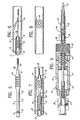
- FIG. 5 illustrates a stent mounted on the outer surface of a balloon of an exemplary embodiment intravascular catheter such as the one shown in FIG. 1.
- FIG. 6 illustrates the advancement of the stent delivery system such as shown in FIG. 5 into an artery which has been damaged by an intravascular procedure, such as an angioplasty procedure, and the location of the elastic cone, prior to the relative axial position adjustment of the delivery sheath and intravascular catheter.
- an intravascular procedure such as an angioplasty procedure
- FIG. 7 illustrates the inflation of the balloon on the intravascular catheter shown in FIG. 1, which expands the stent mounted on the exterior thereof, and the location of the elastic cone after the relative axial position adjustment of the delivery sheath and intravascular catheter.
- FIG. 8 illustrates the expanded stent disposed within a damaged arterial section maintaining the patency thereof.
- FIG. 9 is a partial cross-sectional view of the manipulator shown in FIG. 1.
- FIG. 10 is a perspective view of an alternative manipulator mounted on the proximal end of the delivery system shown in FIG. 1.
- FIG. 11 is a plan view of the manipulator shown in FIG. 10.
- FIG. 12 is an elevational view, partially in section, of the manipulator shown in FIG. 10.
- FIG. 13 is a longitudinal view of a stent delivery system which embodies features of an over-the-wire catheter system.
- FIG. 14 is a partial plan view of the delivery sheath of the stent delivery system depicted in FIG. 13 including optional perfusion ports in the sheath.
- FIG. 15 is a longitudinal view of a stent delivery system wherein the delivery sheath is depicted in its withdrawn position.
- FIG. 16 is a partial plan view of the stent delivery system of FIG. 15 depicting the delivery sheath after it has been withdrawn from the delivery stent.
- FIG. 17 is a cross-sectional view of the distal portion of the delivery sheath of the stent delivery system of FIG. 15, with perfusion ports, illustrating the sheath as it is partially withdrawn from the stent.
- FIG. 18 is a cross-sectional view taken along line 18-18 of FIG. 17, depicting the distal end of the catheter and the elastic cone.
- FIG. 19 is a cross-sectional view taken along line 19-19 of FIG. 17, depicting the sheath in relation to the catheter system.
- FIGS. 1-4 illustrate preferred embodiments of a stent delivery system having features of the invention.
- the delivery system includes a delivery sheath 10 which has a sheath lumen 11 and a catheter 12 disposed within the sheath lumen 11.
- the delivery sheath 10 preferably includes proximal sheath perfusion ports 1 and distal sheath perfusion ports 2.
- the perfusion ports 1, 2 are in fluid communication with the sheath lumen 11.
- the positioning of the ports 1,2 along the sheath 10 may be varied depending upon application. Also, the size, shape, and orientation of the perfusion ports 1, 2 can be changed as needed.
- the perfusion ports in alternative embodiments may be round holes, vertical slots, horizontal slits, and the like.
- the exemplary embodiment intravascular catheter 12 shown in FIG. 1 has an elongated catheter body 13 and a balloon 14 on the distal portion of the catheter body 13.
- a manipulating device 15 is provided on the distal end of the delivery system which is employed to effect relative axial or longitudinal movement between the delivery sheath 10 and the intravascular catheter 12.
- An expandable stent 16, which is to be delivered within a body lumen of a patient, is mounted on the exterior of the balloon 14.
- Figure 1 shows the location of the elastic cone 58 after the relative axial positions of the sheath 10 and catheter 12 are adjusted to expose the expandable stent 16.
- the delivery sheath 10 has a distal port 17 in its distal end which is in fluid communication with the sheath lumen 11 and a proximal port 18 disposed proximally to the distal port.
- the distal portion of the delivery sheath 10 tapers down in a spherical-like manner so that the cross-sectional area is somewhat less in the distal region than is the cross-sectional area of the rest of the delivery sheath.
- a slit 19 extends from the proximal port 18 to a location just proximal to the distal port 17.
- a plurality of slits 59 in the wall of the delivery sheath 10 extend a short distance from the distal port 17. As contemplated, the slits 59 would facilitate the relative axial position adjustment of the delivery sheath 10 and the intravascular catheter 12.
- the intravascular catheter 12 has a distal port 20 and a proximal port 21 which are in fluid communication with a first inner lumen 22, which extends within the distal portion of the catheter 12 and is adapted to slidably receive a guide wire therein.
- a slit 23 extends from the catheter proximal port 21 to a location 24 proximal to the proximal end of the balloon 14.
- the proximal end of the guide wire-receiving first inner lumen 22 is provided with a ramp 25 to guide the proximal end of guide wire 26 out of the proximal port 21 of the intravascular catheter 12 when the catheter is mounted onto the guide wire, as will be discussed hereinafter.
- a second, much longer, inner lumen 27 is provided within the catheter body 13 to direct inflation fluid from the proximal end of the catheter body to the interior of the balloon 14.
- At least one optional catheter perfusion port 3 is located at a proximal portion of the catheter body 13, and is in fluid communication with the first inner lumen 22.
- blood flows through the sheath perfusion ports 1, 2, then through the sheath lumen 11, and ultimately through the catheter perfusion port 3 into the first inner lumen 22.
- the blood passes through the catheter distal port 20 or through optional perfusion ports at the distal end of the catheter body 13 to supply the tissue distal of the balloon 14.
- a stiffening member 28 Proximal to the proximal port 21 in the catheter body 13 is a stiffening member 28 which is disposed in third inner lumen 29 provided within the catheter body 13. As shown in the drawings, the third inner lumen 29 and the first inner lumen 22 may be the same lumen with a plug 30 separating the two lumens.
- the ramp 25 is on the distal side of the plug 30.
- the manipulator 15 on the proximal end of the delivery system has a housing 31 with an interior chamber 32, a cap 33 rotatably mounted onto the distal end of the housing 31, an elongated drive member 34 which has male threads on the exterior thereof and which is at least partially disposed within the interior chamber 32, and a Luer lock 35 which is fixed within the proximal end of the housing 31.
- the proximal end 36 of the delivery sheath 10 is secured to the distal end 37 of the elongated drive member 34 which extends out of the distal end of the housing 31. As shown in more detail in FIG.
- the proximal end 38 of the catheter body 13 passes through a passageway 39 in the elongated drive member 34 and is fixed within the Luer lock 35 by a suitable means such as an adhesive.
- the cap 33 which is rotatably mounted onto the distal end of the housing 31, is provided with an inner threaded collar 40 adapted to threadably engage the threaded exterior of the elongated drive member 34. Rotation of the cap 33 moves the drive member 34 axially to thereby effect relative axial movement between the delivery sheath 10 and the intravascular catheter 12.
- the sheath lumen 11 is axially spaced from the catheter 12, at catheter second inner lumen 27, in a substantially non-abutting manner.
- the stent delivery system of the present invention is used after an intravascular procedure has damaged the arterial lining of a patient to such an extent that the lining needs support to prevent it from collapsing into the arterial passageway thus compromising the sufficiency of the blood flow through the affected vessel.
- a guide wire 26 or other guiding member in place which extends across the damaged section of the artery, such as is shown in FIG. 6.
- the proximal end of the guide wire 26, which extends out of the patient during the entire procedure, is inserted through the elastic cone 58 by threading the guide wire 26 into the small aperture 61 and out of the large aperture 60 of the cone 58.
- the guide wire 26 then is inserted through the distal port 20 in the distal end of the catheter 12 and is advanced proximally through the first inner lumen 22, until the proximal end of the guide wire impacts the ramp 25 and thereby is directed through the proximal port 21.
- the catheter 12 preferably is positioned within the sheath lumen 11 of the delivery sheath 10 so that at least a significant portion of the proximal port 18 in the delivery sheath is in alignment with the proximal port 21 of the intravascular catheter.
- proximal advancement of the guide wire 26 through the first inner lumen 22 of the catheter also will direct the proximal end of the guide wire out of the proximal port 18 in the delivery sheath 10.
- the delivery sheath 10 then is tucked within the elastic cone 58 by inserting the distal end of the delivery sheath 10 into the proximal end and large aperture 60 of the cone 58.
- the proximal end of the guide wire 26 then may be manually held to maintain the position of the guide wire within the vasculature of the patient, while the stent delivery system is advanced over the guide wire and through the vascular system.
- a function of the elastic cone 58 is to facilitate the advancement of the stent delivery system.
- the stent delivery system has a profile suited for successfully maneuvering through the sharp turns and angles of the vasculature of the patient.
- the advancement of the stent delivery system continues until the distal end of the catheter and the distal end of the sheath extend adjacent to, or across, the damaged arterial site.
- the manipulator 15 on the proximal end of the delivery system is actuated by rotating the cap 33 on the proximal end of the housing 31 to move the delivery sheath 10 proximally with respect to the catheter 12 and to thereby expose the stent 16 mounted on the balloon 14.
- the elastic cone 58 disengages the delivery sheath 10 and collapses in engagement about the distal portion of the catheter 12, as is shown in FIG. 1.
- inflation fluid is directed under substantial pressure through the manipulator Luer lock 35 and the catheter inflation lumen 27 in the catheter body 13 to the interior of the balloon 14, expanding the balloon and simultaneously expanding the stent 16 against the wall of the vessel in the target site as shown in FIG. 7.
- the delivery system (both the delivery sheath 10 and the catheter 12), then may be removed from the patient along with the guide wire 26, leaving the expanded stent 16 within the damaged arterial section to maintain the patency thereof, as is shown in FIG. 8.
- the housing 31 of the manipulator 15 can be held in the palm of the physician's hand, the thumb and index finger being used to rotate the cap 33 and thereby to cause the necessary relative motion between the delivery sheath 10 and the intravascular catheter 12 to expose the stent 16 mounted on the balloon 14.
- the physician can operate an inflation device, such as that which is described in U.S. Patent 4,439,185, with his or her free hand, to inject inflation fluid through the Luer lock 35 into the interior of the balloon 14 to inflate the balloon and thereby to expand the stent 16 while holding the delivery system in place with the other hand.
- the manipulator 15 can be actuated again by rotating the cap 33 with the fingers of the hand holding the manipulator 15, to cause relative rotation between the intravascular catheter 12 and the delivery sheath 10, to pull the intravascular catheter 12 back into the distal end of the delivery sheath 10 (or pushing the distal end of the sheath over the distal end of the intravascular catheter 12, depending upon the perspective).
- the entire assembly, including the guide wire 26, then can be removed from the patient.
- the alternative manipulator 50 illustrated in FIGS. 10-12 generally includes a housing 51 with an interior chamber 52 and a slidable element 53 with a depending portion 54 which extends through a slot 55 in the wall of the housing and which is secured to the proximal end of the delivery sheath 10, which extends through an opening provided in the distal end of the housing.
- the catheter 12 extends out the proximal end of the delivery sheath 10, out of an opening in the proximal end of the housing 51, and into a Luer lock 56 secured to the proximal end of the housing.
- the proximal end of the catheter 12 is secured within the Luer lock 56 to be in fluid communication with the second inner inflation lumen 27 of the catheter, so that inflation fluid can be injected through the Luer lock to the interior of the balloon 14 on the catheter to expand the balloon and the stent 16 mounted thereon.
- moving element 53 on the exterior of the housing 51 will effect the relative axial movement between the delivery sheath 10 and the catheter 12, which relative axial movement is required to expose the expandable stent 16 mounted on the balloon 14.
- the slot 55 has narrowed portions near both ends thereof. These harrowed portions have widths that are just slightly smaller than the depending portion 54, so that the position of the slidable element 53 can be locked.
- the underside of the housing 51 may be provided with an undulated surface 57, which is adapted to receive the fingers of an operator to facilitate the gripping thereof.
- an over-the-wire catheter system is employed to carry the delivery sheath and the stent within the vasculature of a patient to the damaged area.
- a guide wire 26 is used to cross the damaged area and to locate the position of interest within the patient, so that the intravascular catheter 12 can reach the area.
- the intravascular catheter 12 has an outer member 77 and an inner member 78 which are aligned coaxially.
- the inner member 78 has an inner lumen 79 which carries a guide wire 26.
- the guide wire can move freely within the inner lumen 79 in an axial direction.
- the delivery sheath 10 is located at the distal end of a distal retractable sheath 74.
- the catheter 12 is slidably disposed within the delivery sheath 10 in the sheath inner lumen 11.
- the port 17 at the distal end of the delivery sheath 10 provides an opening through which the catheter 12 can extend.
- the delivery sheath 10 has a flared portion or an expanded portion located at the distal end of the distal retractable sheath 74. It is contemplated that the delivery sheath 10 can be formed from the same shaft as the distal retractable sheath 74, or can be a separate member (not shown) attached to the distal end of the distal retractable sheath 74.
- the flared or enlarged diameter portion of the delivery sheath 10 must large enough to accommodate the underlying balloon 14 and the expandable stent 16. It also is contemplated that the delivery sheath 10 might not have a flared portion as depicted, in order to reduce the profile of the delivery sheath 10.
- a notch 80 at the distal end of the delivery sheath 10 is incorporated in order to provide a softer and more flexible distal end to the delivery sheath 10.
- a softer distal end for the delivery sheath 10 is desirable, and the notch 80 provides flexibility and the required softness. More than one notch is contemplated to further increase flexibility and softness in the distal end of the delivery sheath 10. If a stiffer, less flexible end is desired, the delivery sheath 10 can be provided without any notch.
- the distal retractable sheath 74 is connected to a proximal retractable sheath 75 comprises a member with a somewhat larger diameter and greater stiffness, than the distal retractable sheath 74.
- the distal end of the sheath will have more flexibility than the proximal end.
- the invention incorporate a retractable sheath characterized by only one diameter along its length, to provide uniform stiffness throughout.
- An elastic cone 58 is attached to the intravascular catheter 12 near its distal tip.
- the elastic cone 58 has a large aperture 60 which is elastic enough to overlay the very distal end of the delivery sheath 10.
- the elastic cone also has a small aperture 61 at its distal end which is attached to the outer member 77 of the over-the-wire catheter by known methods such as heat shrinking or by an adhesive.
- the elastic cone 58 is intended to provide a covering over the distal end of the sheath 10, as the sheath moves through the tortuous vasculature, and will prevent the sheath 10 from getting caught up in the vasculature.
- the intravascular catheter 12 includes optional catheter perfusion ports 5 at a distal end thereof.
- the catheter perfusion ports 5 are in fluid communication with the inner lumen 79 of the inner member 78 of the over-the-wire catheter that carries the guide wire 26.
- An influx of blood optionally may be supplied to the distal perfusion ports 5 through the inner lumen 79, from a blood supply source 6, as is known in the art of perfusion catheters.
- the preferred embodiment delivery sheath 10 includes sheath perfusion ports 4, as horizontal slots, illustrated in FIGS. 14 and 16.
- the perfusion ports 4 enable blood flow through the delivery sheath 10.
- the sheath perfusion ports 4 are useful in one alternative embodiment of the catheter having proximal perfusion ports (not shown). Specifically, as the sheath 10 is retracted, the sheath perfusion ports 4 ensure continuous blood flow in the event the proximal catheter perfusion ports are covered or blocked by the delivery sheath 10 as it is retracted.
- a blood supply 6 that is known in the art directs blood through the inner lumen 79 of the inner member 78 of the over-the-wire catheter. The blood flows through the inner lumen 79 and out of the catheter perfusion ports 5 to the tissue distal from the catheter 12.
- the delivery sheath 10 provides a protective cover for the stent 16 while the stent is being transported through the vasculature of the patient. Once the damaged area has been crossed, the stent then is ready to be deployed.
- a manipulator handle 70 is utilized to retract the delivery sheath 10.
- the proximal end (not shown) of the proximal retractable sheath 75 is attached to a connector 72.
- a sheath retraction switch 71 can be operated by the thumb of the physician by moving the switch in the proximal direction.
- the sheath retraction switch 71 is attached to the connector 72, which is slidably mounted in an elongated slot 73. As the sheath retraction switch 71 is moved in the proximal direction, the proximal retractable sheath 75 and the distal retractable sheath 74 also move in the proximal direction.
- the delivery sheath 10 is connected to the distal retractable sheath 74, it too moves in the proximal direction a sufficient distance to expose the expandable stent 16 and the balloon 14. It is preferred to position a radiopaque marker 67 near the distal end of the delivery sheath 10 so that the physician can determine when the sheath 10 has been withdrawn a sufficient distance so as not to interfere with the deployment of the stent 16.
- the radiopaque marker can be positioned at the location 68 (FIG. 14) rather than at the location indicated by the radiopaque marker 67.
- the radiopaque marker 68 When the radiopaque marker 68 is positioned on the distal retractable sheath 74, it has a lower profile than the radiopaque marker 67, thus allowing the delivery sheath 10 to cross an occluded area more easily.
- the balloon 14 In order to deploy the expandable stent 16, the balloon 14 is inflated with an inflation fluid through an inflation port 65. As shown in FIG. 17, an inflation fluid supply 7, known in the art, directs inflation fluid into the balloon 14. After the expandable stent 16 has been deployed, the balloon 14 is deflated and the intravascular catheter 12 is removed from the vasculature of the patient.
- the dimensions of the intravascular catheter generally follow the dimensions of intravascular catheters used in angioplasty procedures in the same arterial location.
- the length of a catheter for use in the coronary arteries is about 150 cm (59 inches)
- the outer diameter of the catheter shaft is about 0. 89 mm (0.035 inch)
- the length of the balloon typically is about 2 cm (0.79 inch)
- the inflated diameter about 1 mm to about 8 mm (0.04 to 0.31 inch).
- the materials of construction may be selected from those used in conventional balloon angioplasty catheters, such as those described in the patents referenced hereinabove.
- the delivery sheath generally will be slightly shorter than the intravascular catheter, e.g. , by about the length of the manipulating devices 15 or 50, with an inner diameter large enough to accommodate the intravascular catheter and to allow the catheter free longitudinal movement within the delivery sheath.
- the sheath and the catheter shaft can be made of conventional polyethylene tubing.
- the delivery system can be employed to deliver stents to locations within other body lumens such as the urethra or the Fallopian tubes so that the stents can be expanded to maintain the patency of these body lumens.
- body lumens such as the urethra or the Fallopian tubes
Abstract
A stent delivery method and system are disclosed. The system
generally includes an elongated delivery sheath (10) and a perfusion catheter (12)
disposed within a sheath lumen (11) of the sheath having an expandable member
(14) on its distal extremity. The sheath includes perfusion ports (1,2) to maintain
blood flow to perfusion ports in the catheter during delivery of the stent. A
manipulating device (15, 33, 34) is provided at the proximal end of the delivery
system to effect relative axial movement between the sheath and the catheter so as
to expose the stent (16) mounted on the expandable member (14) on the catheter
within a body lumen such as a coronary artery and to allow the expansion of the
stent by the expansion of the expandable member.
Description
This invention generally relates to devices for the treatment of heart
disease and, more particularly, to endoarterial prostheses, which commonly are
called stents.
Several interventional treatment modalities presently are used for
heart disease, including balloon and laser angioplasty, atherectomy, and by-pass
surgery. In typical balloon angioplasty procedures, a guiding catheter having a
pre-formed distal tip percutaneously is introduced through the femoral artery into
the cardiovascular system of a patient in a conventional Seldinger technique, and
is advanced within the cardiovascular system until the distal tip of the guiding
catheter is seated in the ostium of a desired coronary artery. A guide wire is
positioned within an inner lumen of a dilatation catheter and then the catheter is
advanced over the guide wire, through the guiding catheter to the distal end of the
guiding catheter. The guide wire first is advanced out of the distal end of the
guiding catheter into the coronary vasculature of the patient until the distal end of
the guide wire crosses a lesion to be dilated, then the dilatation catheter having an
inflatable balloon on the distal portion thereof is advanced into the coronary
anatomy over the previously introduced guide wire until the balloon of the
dilatation catheter properly is positioned across the lesion.
Once in position across the lesion, the balloon, which is made of
relatively inelastic materials, is inflated to a predetermined size with radiopaque
liquid at relatively high pressure (e.g., greater than 4.052 bars (4 atmospheres))
to compress the arteriosclerotic plaque of the lesion against the inside of the artery
wall and to otherwise expand the inner lumen of the artery. The balloon then is
deflated so that blood flow can be resumed through the dilated artery and the
dilatation catheter can be removed therefrom.
Further details of dilatation catheters, guide wires, and devices
associated therewith for angioplasty procedures can be found in U.S. Patent
4,323,071 (Simpson-Robert); U.S. Patent 4,439,185 (Lindquist); U.S. Patent
4,516,972 (Samson); U.S. Patent 4,538,622 (Samson, et al.); U.S. Patent
4,554,929 (Samson, et al.); U.S. Patent 4,616,652 (Simpson); U.S. Patent
4,638,805 (Powell); and U.S. Patent 4,748,982 (Horzewski, et al.).
A problem which can occur during balloon angioplasty procedures
is the formation of intimal flaps, which can collapse and occlude the artery when
the balloon is deflated at the end of the angioplasty procedure. In the event of a
partial or total occlusion of a coronary artery by the collapse of a dissected arterial
lining after the balloon is deflated, the patient is put in an extremely dangerous
situation requiring immediate medical attention, particularly in the coronary
arteries. Another problem characteristic of balloon angioplasty procedures is the
large number of patients who are subject to restenosis in the treated artery. In the
case of restenosis, a previously treated artery may once again be subjected to
balloon angioplasty or even to less conservative treatment such as by-pass surgery.
A significant focus of recent development work in the treatment of heart
disease has been directed to endoprosthetic devices called stents. Stents are
generally cylindrically-shaped intravascular devices which are placed within a
damaged artery to hold it open. A stent can be used to prevent restenosis and to
maintain the patency of blood vessel immediately after other intravascular
treatments. In some circumstances, stents also can be used as the primary
treatment device when expanded to dilate a stenosis and then left in place.
But the rapid and effective delivery of a stent to the desire location
within the vasculature has been found to be difficult, particularly in those situations
in which an intimal flap has occluded an artery. Attempts to advance a stent into
regions of coronary arteries occluded by dissected arterial linings have not been
very successful.
Two basic methods and systems have been developed for delivering
stents to desired locations within body lumens. One method and system involves
compressing or otherwise reducing the diameter of an expandable stent, disposing
the compressed stent within a lumen provided in the distal end of a tubular
catheter, advancing the catheter through the vasculature of the patient until the
distal end of the catheter is immediately adjacent to the desired vascular location
and then pushing the stent out of the distal end of the catheter into the desired
location. Once out of the catheter, the compressed stent expands or is expanded
to thereby hold open the artery or other body lumen into which it is placed.
Another method and system involves disposing a compressed or
otherwise small diameter stent about an expandable member, such as a balloon, on
the distal end of a catheter, advancing the catheter through the vascular system of
a patient until the stent is in the desired location within a blood vessel, and then
expanding the expandable member on the catheter to expand the stent within the
blood vessel. The expanded expandable member then is contracted or deflated and
the catheter withdrawn, leaving the expanded stent within the blood vessel, holding
open the passageway thereof.
The following references illustrate various types of stents and stent
delivery systems. The list is meant to be exemplary, not exhaustive on the subject.
| U.S. 3,868,956 | U.S. 4,503,569 | U.S. 4,512,338 |
| U.S. 4,553,545 | U.S. 4,560,374 | U.S. 4,655,771 |
| U.S. 4,665,918 | U.S. 4,733,665 | U.S. 4,760,849 |
| U.S. 4,762,128 | U.S. 4,768,507 | U.S. 4,795,458 |
| U.S. 4,800,882 | U.S. 4,830,003 | U.S. 4,856,516 |
| U.S. 4,878,906 | U.S. 4,886,062 | U.S. 4,907,336 |
| U.S. 4,913,141 | U.S. 4,923,464 | U.S. 4,950,227 |
| U.S. 5,458,615 |
What has been needed and heretofore unavailable is a stent delivery
system which can be used quickly and easily in a wide variety of situations and
particularly in emergency situations, when a dissected arterial lining has collapsed
and has occluded the flow of blood to a vital organ. The present invention satisfies
this need.
In addition, because the expandable member such as a balloon is
inflated, the flow of blood in the artery or vessel being treated is occluded. The
balloon only can be inflated for a limited amount of time, typically on the order
of 15 to 60 seconds. A longer inflation time would be desirable because it would
allow more time for the surgeon to deploy the stent, allow maximum stent-to-vessel
conformity, and permit good seating in the artery of the stent. On the other
hand, risks of prolonged balloon inflation time include angina or ischemic
conditions in the tissue distal to the catheter.
The importance of continuous blood flow during percutaneous
transluminal coronary angioplasty or during procedures performed in the peripheral
vascular is well recognized. Indeed, a perfusion-type dilatation catheter for
angioplasty has been introduced into the marketplace by Advanced Cardiovascular
Systems, Inc. This catheter, which can take the form of an over-the-wire, a fixed
wire, or a rapid-exchange type catheter, has one or more perfusion ports proximal
to and one or more perfusion ports distal to, the dilatation balloon. The perfusion
ports are in fluid communication with a guide wire- receiving inner lumen which
extends to the distal end of the catheter. When the balloon is inflated to dilate a
stenosis, oxygenated blood in the artery or aorta, or both, is forced through the
proximal perfusion ports, through the inner lumen of the catheter, and out of the
distal perfusion ports.
The rapid-exchange version of the perfusion-type dilatation catheter
has a short, guide wire-receiving sleeve or inner lumen which extends through a
distal portion of the catheter. The structure of the catheter allows for the rapid
exchange of the catheter without the need for an exchange wire and without adding
a guide wire extension to the proximal end of the guide wire. Details of such a
rapid-exchange perfusion catheter are disclosed in, for example, U.S. Patent No.
5,040,548 (Yock).
Also of interest is U.S. Patent 5,368,566 (Crocker), which discloses
a delivery and temporary stent catheter having a reinforced perfusion lumen. The
temporary stent in the Crocker reference is used only for maintaining patency of
a body lumen while permitting perfusion of fluid through the lumen. U.S. Patent
No. 5,368,566 is not directed to the delivery of stents after angioplasty procedures.
U.S. Patent 5,222,971 (Willard et al.) discloses a temporary stent
for supporting a region of a vessel comprising a stent portion and an actuator
portion. The stent portion has an elongate perfusable vessel-supporting portion,
wherein the stent provides a path radially, as well axially or longitudinally, for
fluid flow.
There is, however, still a need for a stent delivery system that
includes a mechanism for perfusing blood during delivery of the stent to the
deployment site.
The present invention is directed to an improved stent delivery
system which can position a stent quickly and easily into an occluded region of a
blood vessel. In a preferred embodiment, the present invention stent delivery
system includes a means for perfusing fluid.
One preferred embodiment of the present invention is directed to a
catheter assembly for maintaining the patency of a body lumen for a period of time
sufficient to permit delivery of an expandable stent within the body lumen, wherein
the assembly comprises an elongated delivery sheath having proximal and distal
ends, a sheath lumen extending therein, a first port in the distal end being in fluid
communication with the sheath lumen, and at least one sheath perfusion port at the
proximal end in fluid communication with the sheath lumen.
Embodiments of the present invention also include an elongated
catheter slidably disposed within the sheath lumen of the sheath, an expandable
member proximally adjacent to the distal end of the catheter which receives on the
exterior thereof the expandable stent, an inner lumen extending the length of said
elongated catheter for receiving a guiding member therein and which extends the
entire length of the inner lumen, and at least one catheter perfusion port in the
catheter in fluid communication with the inner lumen. Further included are means
for adjusting the relative axial positions of the catheter and the sheath to expose the
expandable member so that expansion thereof expands the expandable stent.
Preferably, both the delivery sheath and the catheter have slits in the
walls thereof which extend distally from their proximal ports to facilitate the rapid
removal of these devices from the guide wire upon the withdrawal of the delivery
system from the vascular system of the patient after the delivery of a stent. The
distal end of the delivery sheath also may have slits in the walls thereof which
extend a short distance proximally from its distal end, to facilitate in the relative
axial position adjustment of the delivery sheath and catheter.
In a typical situation, the guide wire used to deliver a dilatation
catheter through the vascular system to a stenotic region therein is left within the
patient after the dilatation catheter has been removed therefrom. To maintain
access to the stenotic region, the distal end of the guide wire should be positioned
so that it crosses the stenotic region where the stent is to be placed.
The proximal end of the guide wire, which extends out of the
patient, first is inserted through an elastic cone by threading the guide wire into the
smaller aperture of the cone and out of the larger of the two apertures of the cone.
Then the guide wire is inserted through the port in the distal end of the
intravascular catheter, which has a stent mounted on the expandable member. The
intravascular catheter is disposed within the delivery sheath with the distal end of
the catheter extending out of the port in the distal end of the delivery sheath to
facilitate the insertion of the proximal end of the guide wire.
The relative axial position between the delivery sheath and
intravascular catheter is adjusted so that the expandable member on the distal
extremity of the intravascular catheter with the expandable stent mounted thereon
is pulled back into the inner lumen of the delivery sheath. The distal end of the
delivery sheath then is tucked within the large aperture of the elastic cone.
Tucking the delivery sheath within the elastic cone aids the advancement of the
stent delivery system through the vascular system by providing the system with a
profile suited for making turns through tortuous vessels. The delivery sheath and
the catheter therein then are advanced through the vascular system, preferably over
a guide wire which extends from outside the patient to the desired coronary artery,
until the stent mounted on the expandable member of the intravascular catheter is
positioned within the stenotic region of the target vessel.
The relative axial positions of the delivery sheath and the
intravascular catheter having the stent thereon are adjusted so that the sheath is
withdrawn proximally (in a direction away from the patient) to expose the distal
end of the vascular catheter and the expandable stent. As the relative axial
positions are adjusted, the cone disengages from the sheath and collapses upon the
distal end of the catheter. Once the stent is completely out of the delivery sheath,
the expandable member on the intravascular catheter can be expanded to expand
the stent against the walls of the blood vessel. After expanding the stent, the
expandable member on the vascular catheter is contracted so that the catheter can
be removed from the patient, leaving the expanded stent in its desired position in
the target vessel.
During delivery of the stent to the deployment site, the perfusion
ports within the sheath and the catheter provide continuous blood flow via the
sheath lumen of the sheath and the inner lumen of the catheter. From the inner
lumen, the effluent blood passes through the perfusion ports at the distal end of the
catheter to the tissue distal to the catheter. Even as the sheath is withdrawn, the
perfusion ports in the sheath enable continuous flow of blood to the perfusion ports
in the catheter shaft.
Beneficially, the present invention perfusion ports in the sheath and
catheter prevent or minimize ischemic conditions from developing in the patient.
Moreover, the perfusion of blood distal to the inflated balloon allows for long term
dilatations.
The delivery sheath and the catheter may be withdrawn together or
the sheath may be withdrawn first, followed by withdrawal of the catheter. The
sheath and the catheter can be peeled away from the guide wire, with the guide
wire sliding through the slits which extend distally from the proximal ports of the
catheter. The exposed section of the guide wire is secured, e.g., manually held in
place, so that the sheath and the intravascular catheter can be pulled off the
proximal end of the guide wire.
In one exemplary embodiment of the invention, an over-the-wire
catheter system is used to deliver a stent to a location in the vascular system. The
over-the-wire catheter includes a proximal shaft and a distal shaft which are
retractable in the proximal direction by operation of a sheath retraction switch on
a delivery handle. An elongated sheath is at the distal end of the distal shaft and
covers and protects the stent and balloon member on the catheter shaft during
intravascular delivery. When the sheath retraction switch is moved in the proximal
direction, the sheath is caused to move proximally, thereby exposing the stent so
that it may be deployed.
The delivery system of the invention effectively can deliver a stent
to a desired location within a vessel of a patient, can allow the stent to be secured
within the desired location, and can be removed quickly and easily. These and
other advantages of the present invention will become more apparent from the
following detailed description when taken in conjunction with the accompanying
exemplary drawings.
FIGURE 1 is a partial longitudinal cross-sectional view of a stent
delivery system which embodies features of the invention including perfusion ports
in the catheter and sheath.
FIG. 2 is a top view of the delivery sheath with perfusion ports and
elastic cone of the stent delivery system shown in FIG. 1.
FIG. 3 is a transverse cross-sectional view taken along the lines 3-3
shown in FIG. 1.
FIG. 4 is a transverse cross-sectional view taken along the lines 4-4
shown in FIG. 1.
FIG. 5 illustrates a stent mounted on the outer surface of a balloon
of an exemplary embodiment intravascular catheter such as the one shown in FIG. 1.
FIG. 6 illustrates the advancement of the stent delivery system such
as shown in FIG. 5 into an artery which has been damaged by an intravascular
procedure, such as an angioplasty procedure, and the location of the elastic cone,
prior to the relative axial position adjustment of the delivery sheath and
intravascular catheter.
FIG. 7 illustrates the inflation of the balloon on the intravascular
catheter shown in FIG. 1, which expands the stent mounted on the exterior thereof,
and the location of the elastic cone after the relative axial position adjustment of
the delivery sheath and intravascular catheter.
FIG. 8 illustrates the expanded stent disposed within a damaged
arterial section maintaining the patency thereof.
FIG. 9 is a partial cross-sectional view of the manipulator shown in
FIG. 1.
FIG. 10 is a perspective view of an alternative manipulator mounted
on the proximal end of the delivery system shown in FIG. 1.
FIG. 11 is a plan view of the manipulator shown in FIG. 10.
FIG. 12 is an elevational view, partially in section, of the
manipulator shown in FIG. 10.
FIG. 13 is a longitudinal view of a stent delivery system which
embodies features of an over-the-wire catheter system.
FIG. 14 is a partial plan view of the delivery sheath of the stent
delivery system depicted in FIG. 13 including optional perfusion ports in the
sheath.
FIG. 15 is a longitudinal view of a stent delivery system wherein the
delivery sheath is depicted in its withdrawn position.
FIG. 16 is a partial plan view of the stent delivery system of FIG. 15
depicting the delivery sheath after it has been withdrawn from the delivery stent.
FIG. 17 is a cross-sectional view of the distal portion of the delivery
sheath of the stent delivery system of FIG. 15, with perfusion ports, illustrating the
sheath as it is partially withdrawn from the stent.
FIG. 18 is a cross-sectional view taken along line 18-18 of FIG. 17,
depicting the distal end of the catheter and the elastic cone.
FIG. 19 is a cross-sectional view taken along line 19-19 of FIG. 17,
depicting the sheath in relation to the catheter system.
FIGS. 1-4 illustrate preferred embodiments of a stent delivery system
having features of the invention. Generally, the delivery system includes a
delivery sheath 10 which has a sheath lumen 11 and a catheter 12 disposed within
the sheath lumen 11. As shown in FIG. 1, the delivery sheath 10 preferably
includes proximal sheath perfusion ports 1 and distal sheath perfusion ports 2. The
perfusion ports 1, 2 are in fluid communication with the sheath lumen 11. The
positioning of the ports 1,2 along the sheath 10, of course, may be varied
depending upon application. Also, the size, shape, and orientation of the perfusion
ports 1, 2 can be changed as needed. For example, the perfusion ports in
alternative embodiments may be round holes, vertical slots, horizontal slits, and
the like.
The exemplary embodiment intravascular catheter 12 shown in
FIG. 1 has an elongated catheter body 13 and a balloon 14 on the distal portion of
the catheter body 13. A manipulating device 15 is provided on the distal end of
the delivery system which is employed to effect relative axial or longitudinal
movement between the delivery sheath 10 and the intravascular catheter 12. An
expandable stent 16, which is to be delivered within a body lumen of a patient, is
mounted on the exterior of the balloon 14. During the advancement of the stent
delivery system through the vascular system to the region of an occlusion, the
sheath 10 is tucked within an elastic cone 58. Figure 1 shows the location of the
elastic cone 58 after the relative axial positions of the sheath 10 and catheter 12 are
adjusted to expose the expandable stent 16.
The delivery sheath 10 has a distal port 17 in its distal end which is
in fluid communication with the sheath lumen 11 and a proximal port 18 disposed
proximally to the distal port. The distal portion of the delivery sheath 10 tapers
down in a spherical-like manner so that the cross-sectional area is somewhat less
in the distal region than is the cross-sectional area of the rest of the delivery
sheath. A slit 19 extends from the proximal port 18 to a location just proximal to
the distal port 17. In one embodiment, a plurality of slits 59 in the wall of the
delivery sheath 10 extend a short distance from the distal port 17. As
contemplated, the slits 59 would facilitate the relative axial position adjustment of
the delivery sheath 10 and the intravascular catheter 12.
The intravascular catheter 12 has a distal port 20 and a proximal port
21 which are in fluid communication with a first inner lumen 22, which extends
within the distal portion of the catheter 12 and is adapted to slidably receive a
guide wire therein. A slit 23 extends from the catheter proximal port 21 to a
location 24 proximal to the proximal end of the balloon 14. The proximal end of
the guide wire-receiving first inner lumen 22 is provided with a ramp 25 to guide
the proximal end of guide wire 26 out of the proximal port 21 of the intravascular
catheter 12 when the catheter is mounted onto the guide wire, as will be discussed
hereinafter. A second, much longer, inner lumen 27 is provided within the
catheter body 13 to direct inflation fluid from the proximal end of the catheter
body to the interior of the balloon 14.
At least one optional catheter perfusion port 3 is located at a
proximal portion of the catheter body 13, and is in fluid communication with the
first inner lumen 22. Thus, blood flows through the sheath perfusion ports 1, 2,
then through the sheath lumen 11, and ultimately through the catheter perfusion
port 3 into the first inner lumen 22. The blood passes through the catheter distal
port 20 or through optional perfusion ports at the distal end of the catheter body
13 to supply the tissue distal of the balloon 14.
Proximal to the proximal port 21 in the catheter body 13 is a
stiffening member 28 which is disposed in third inner lumen 29 provided within
the catheter body 13. As shown in the drawings, the third inner lumen 29 and the
first inner lumen 22 may be the same lumen with a plug 30 separating the two
lumens. The ramp 25 is on the distal side of the plug 30.
As illustrated in FIGS. 1 and 9, the manipulator 15 on the proximal
end of the delivery system has a housing 31 with an interior chamber 32, a cap 33
rotatably mounted onto the distal end of the housing 31, an elongated drive
member 34 which has male threads on the exterior thereof and which is at least
partially disposed within the interior chamber 32, and a Luer lock 35 which is
fixed within the proximal end of the housing 31. The proximal end 36 of the
delivery sheath 10 is secured to the distal end 37 of the elongated drive member
34 which extends out of the distal end of the housing 31. As shown in more detail
in FIG. 9, the proximal end 38 of the catheter body 13 passes through a
passageway 39 in the elongated drive member 34 and is fixed within the Luer lock
35 by a suitable means such as an adhesive. The cap 33, which is rotatably
mounted onto the distal end of the housing 31, is provided with an inner threaded
collar 40 adapted to threadably engage the threaded exterior of the elongated drive
member 34. Rotation of the cap 33 moves the drive member 34 axially to thereby
effect relative axial movement between the delivery sheath 10 and the intravascular
catheter 12. As can be seen from FIGS. 1 and 6, the sheath lumen 11 is axially
spaced from the catheter 12, at catheter second inner lumen 27, in a substantially
non-abutting manner. Thus, when the delivery sheath 10 overlies the intravascular
catheter 12, there is little or no contact present at the interface between the sheath
lumen 27 proximal to the distal end of the intravascular catheter 12.
In a typical situation, the stent delivery system of the present
invention is used after an intravascular procedure has damaged the arterial lining
of a patient to such an extent that the lining needs support to prevent it from
collapsing into the arterial passageway thus compromising the sufficiency of the
blood flow through the affected vessel. In these situations, there usually is a guide
wire 26 (or other guiding member) in place which extends across the damaged
section of the artery, such as is shown in FIG. 6. The proximal end of the guide
wire 26, which extends out of the patient during the entire procedure, is inserted
through the elastic cone 58 by threading the guide wire 26 into the small aperture
61 and out of the large aperture 60 of the cone 58. The guide wire 26 then is
inserted through the distal port 20 in the distal end of the catheter 12 and is
advanced proximally through the first inner lumen 22, until the proximal end of
the guide wire impacts the ramp 25 and thereby is directed through the proximal
port 21.
The catheter 12 preferably is positioned within the sheath lumen 11
of the delivery sheath 10 so that at least a significant portion of the proximal port
18 in the delivery sheath is in alignment with the proximal port 21 of the
intravascular catheter. In this manner, proximal advancement of the guide wire
26 through the first inner lumen 22 of the catheter also will direct the proximal end
of the guide wire out of the proximal port 18 in the delivery sheath 10. The
delivery sheath 10 then is tucked within the elastic cone 58 by inserting the distal
end of the delivery sheath 10 into the proximal end and large aperture 60 of the
cone 58. The proximal end of the guide wire 26 then may be manually held to
maintain the position of the guide wire within the vasculature of the patient, while
the stent delivery system is advanced over the guide wire and through the vascular
system.
A function of the elastic cone 58 is to facilitate the advancement of
the stent delivery system. By tucking the distal end of delivery sheath 10 within
the cone 58 as shown in FIG. 6, the stent delivery system has a profile suited for
successfully maneuvering through the sharp turns and angles of the vasculature of
the patient.
The advancement of the stent delivery system continues until the
distal end of the catheter and the distal end of the sheath extend adjacent to, or
across, the damaged arterial site. Next, the manipulator 15 on the proximal end
of the delivery system is actuated by rotating the cap 33 on the proximal end of the
housing 31 to move the delivery sheath 10 proximally with respect to the catheter
12 and to thereby expose the stent 16 mounted on the balloon 14. The elastic cone
58 disengages the delivery sheath 10 and collapses in engagement about the distal
portion of the catheter 12, as is shown in FIG. 1.
When the balloon and the stent mounted thereon properly are placed
within the damaged artery, inflation fluid is directed under substantial pressure
through the manipulator Luer lock 35 and the catheter inflation lumen 27 in the
catheter body 13 to the interior of the balloon 14, expanding the balloon and
simultaneously expanding the stent 16 against the wall of the vessel in the target
site as shown in FIG. 7. The delivery system (both the delivery sheath 10 and the
catheter 12), then may be removed from the patient along with the guide wire 26,
leaving the expanded stent 16 within the damaged arterial section to maintain the
patency thereof, as is shown in FIG. 8.
The housing 31 of the manipulator 15 can be held in the palm of the
physician's hand, the thumb and index finger being used to rotate the cap 33 and
thereby to cause the necessary relative motion between the delivery sheath 10 and
the intravascular catheter 12 to expose the stent 16 mounted on the balloon 14.
The physician can operate an inflation device, such as that which is described in
U.S. Patent 4,439,185, with his or her free hand, to inject inflation fluid through
the Luer lock 35 into the interior of the balloon 14 to inflate the balloon and
thereby to expand the stent 16 while holding the delivery system in place with the
other hand. Upon deflating the balloon 14, the manipulator 15 can be actuated
again by rotating the cap 33 with the fingers of the hand holding the manipulator
15, to cause relative rotation between the intravascular catheter 12 and the delivery
sheath 10, to pull the intravascular catheter 12 back into the distal end of the
delivery sheath 10 (or pushing the distal end of the sheath over the distal end of the
intravascular catheter 12, depending upon the perspective). The entire assembly,
including the guide wire 26, then can be removed from the patient.
The alternative manipulator 50 illustrated in FIGS. 10-12 generally
includes a housing 51 with an interior chamber 52 and a slidable element 53 with
a depending portion 54 which extends through a slot 55 in the wall of the housing
and which is secured to the proximal end of the delivery sheath 10, which extends
through an opening provided in the distal end of the housing. The catheter 12
extends out the proximal end of the delivery sheath 10, out of an opening in the
proximal end of the housing 51, and into a Luer lock 56 secured to the proximal
end of the housing. The proximal end of the catheter 12 is secured within the Luer
lock 56 to be in fluid communication with the second inner inflation lumen 27 of
the catheter, so that inflation fluid can be injected through the Luer lock to the
interior of the balloon 14 on the catheter to expand the balloon and the stent 16
mounted thereon. As is evident from FIG. 10, moving element 53 on the exterior
of the housing 51 will effect the relative axial movement between the delivery
sheath 10 and the catheter 12, which relative axial movement is required to expose
the expandable stent 16 mounted on the balloon 14. The slot 55 has narrowed
portions near both ends thereof. These harrowed portions have widths that are just
slightly smaller than the depending portion 54, so that the position of the slidable
element 53 can be locked. The underside of the housing 51 may be provided with
an undulated surface 57, which is adapted to receive the fingers of an operator to
facilitate the gripping thereof.
In another exemplary embodiment of the invention, as depicted in
FIGS. 13-19, an over-the-wire catheter system is employed to carry the delivery
sheath and the stent within the vasculature of a patient to the damaged area. A
guide wire 26 is used to cross the damaged area and to locate the position of
interest within the patient, so that the intravascular catheter 12 can reach the area.
As is typical in over-the-wire catheter systems, the intravascular
catheter 12 has an outer member 77 and an inner member 78 which are aligned
coaxially. The inner member 78 has an inner lumen 79 which carries a guide wire
26. The guide wire can move freely within the inner lumen 79 in an axial
direction.
In keeping with the invention, as depicted in FIGS. 13-19, the
delivery sheath 10 is located at the distal end of a distal retractable sheath 74. The
catheter 12 is slidably disposed within the delivery sheath 10 in the sheath inner
lumen 11. The port 17 at the distal end of the delivery sheath 10 provides an
opening through which the catheter 12 can extend.
The delivery sheath 10 has a flared portion or an expanded portion
located at the distal end of the distal retractable sheath 74. It is contemplated that
the delivery sheath 10 can be formed from the same shaft as the distal retractable
sheath 74, or can be a separate member (not shown) attached to the distal end of
the distal retractable sheath 74. The flared or enlarged diameter portion of the
delivery sheath 10 must large enough to accommodate the underlying balloon 14
and the expandable stent 16. It also is contemplated that the delivery sheath 10
might not have a flared portion as depicted, in order to reduce the profile of the
delivery sheath 10.
A notch 80 at the distal end of the delivery sheath 10 is incorporated
in order to provide a softer and more flexible distal end to the delivery sheath 10.
When the intravascular catheter 12 is being urged through the vasculature of the
patient, a softer distal end for the delivery sheath 10 is desirable, and the notch 80
provides flexibility and the required softness. More than one notch is
contemplated to further increase flexibility and softness in the distal end of the
delivery sheath 10. If a stiffer, less flexible end is desired, the delivery sheath 10
can be provided without any notch.
The distal retractable sheath 74 is connected to a proximal retractable
sheath 75 comprises a member with a somewhat larger diameter and greater
stiffness, than the distal retractable sheath 74. Thus, the distal end of the sheath
will have more flexibility than the proximal end. It also is contemplated that the
invention incorporate a retractable sheath characterized by only one diameter along
its length, to provide uniform stiffness throughout.
An elastic cone 58 is attached to the intravascular catheter 12 near
its distal tip. The elastic cone 58 has a large aperture 60 which is elastic enough
to overlay the very distal end of the delivery sheath 10. The elastic cone also has
a small aperture 61 at its distal end which is attached to the outer member 77 of the
over-the-wire catheter by known methods such as heat shrinking or by an adhesive.
The elastic cone 58 is intended to provide a covering over the distal end of the
sheath 10, as the sheath moves through the tortuous vasculature, and will prevent
the sheath 10 from getting caught up in the vasculature.
Further, the intravascular catheter 12 includes optional catheter
perfusion ports 5 at a distal end thereof. The catheter perfusion ports 5 are in fluid
communication with the inner lumen 79 of the inner member 78 of the over-the-wire
catheter that carries the guide wire 26. An influx of blood optionally may be
supplied to the distal perfusion ports 5 through the inner lumen 79, from a blood
supply source 6, as is known in the art of perfusion catheters.
In addition, the preferred embodiment delivery sheath 10 includes
sheath perfusion ports 4, as horizontal slots, illustrated in FIGS. 14 and 16. Of
course, the size, shape, location, and orientation of the sheath perfusion ports 4
may be adjusted to accommodate particular applications. The perfusion ports 4
enable blood flow through the delivery sheath 10. The sheath perfusion ports 4 are
useful in one alternative embodiment of the catheter having proximal perfusion
ports (not shown). Specifically, as the sheath 10 is retracted, the sheath perfusion
ports 4 ensure continuous blood flow in the event the proximal catheter perfusion
ports are covered or blocked by the delivery sheath 10 as it is retracted.
A blood supply 6 that is known in the art directs blood through the
inner lumen 79 of the inner member 78 of the over-the-wire catheter. The blood
flows through the inner lumen 79 and out of the catheter perfusion ports 5 to the
tissue distal from the catheter 12.
As described above, the delivery sheath 10 provides a protective
cover for the stent 16 while the stent is being transported through the vasculature
of the patient. Once the damaged area has been crossed, the stent then is ready to
be deployed.
In order to deploy the stent, a manipulator handle 70 is utilized to
retract the delivery sheath 10. The proximal end (not shown) of the proximal
retractable sheath 75 is attached to a connector 72. A sheath retraction switch 71
can be operated by the thumb of the physician by moving the switch in the
proximal direction. The sheath retraction switch 71 is attached to the connector 72,
which is slidably mounted in an elongated slot 73. As the sheath retraction switch
71 is moved in the proximal direction, the proximal retractable sheath 75 and the
distal retractable sheath 74 also move in the proximal direction. Because the
delivery sheath 10 is connected to the distal retractable sheath 74, it too moves in
the proximal direction a sufficient distance to expose the expandable stent 16 and
the balloon 14. It is preferred to position a radiopaque marker 67 near the distal
end of the delivery sheath 10 so that the physician can determine when the sheath
10 has been withdrawn a sufficient distance so as not to interfere with the
deployment of the stent 16. Alternatively, the radiopaque marker can be
positioned at the location 68 (FIG. 14) rather than at the location indicated by the
radiopaque marker 67. When the radiopaque marker 68 is positioned on the distal
retractable sheath 74, it has a lower profile than the radiopaque marker 67, thus
allowing the delivery sheath 10 to cross an occluded area more easily.
In order to deploy the expandable stent 16, the balloon 14 is inflated
with an inflation fluid through an inflation port 65. As shown in FIG. 17, an
inflation fluid supply 7, known in the art, directs inflation fluid into the balloon 14.
After the expandable stent 16 has been deployed, the balloon 14 is deflated and the
intravascular catheter 12 is removed from the vasculature of the patient.
In the preferred embodiment of the present invention, the dimensions
of the intravascular catheter generally follow the dimensions of intravascular
catheters used in angioplasty procedures in the same arterial location. Typically,
the length of a catheter for use in the coronary arteries is about 150 cm (59
inches), the outer diameter of the catheter shaft is about 0. 89 mm (0.035 inch), the
length of the balloon typically is about 2 cm (0.79 inch) and the inflated diameter
about 1 mm to about 8 mm (0.04 to 0.31 inch).
The materials of construction may be selected from those used in
conventional balloon angioplasty catheters, such as those described in the patents
referenced hereinabove. The delivery sheath generally will be slightly shorter than
the intravascular catheter, e.g., by about the length of the manipulating devices 15
or 50, with an inner diameter large enough to accommodate the intravascular
catheter and to allow the catheter free longitudinal movement within the delivery
sheath. The sheath and the catheter shaft can be made of conventional
polyethylene tubing.
While the present invention has been described herein in terms of
delivering an expandable stent to a desired location within a blood vessel of a
patient, the delivery system can be employed to deliver stents to locations within
other body lumens such as the urethra or the Fallopian tubes so that the stents can
be expanded to maintain the patency of these body lumens. Various changes and
improvements also may be made to the invention without departing from the scope
thereof.
Claims (12)
- A catheter assembly for maintaining the patency of a body lumen for a period of time sufficient to permit delivery of an expandable stent (16) within the body lumen, comprising:an elongated sheath (10) having proximal and distal ends, a sheath lumen (11) extending therein, a first port (17) in the distal end being in fluid communication with the sheath lumen, and at least one sheath perfusion port (1, 2) in the sheath in fluid communication with the sheath lumen;an elongated catheter (12) disposed within the sheath lumen (11) and having a proximal and a distal end wherein the catheter includes at least one catheter perfusion port (3), the elongated catheter having an outer member and an inner member, an expandable member (14) proximally adjacent to the distal end of the outer member that receives the expandable stent (16) on the exterior thereof, an inner lumen (22) within said inner member that receives a guiding member (26) therein and that extends the entire length of the inner lumen, the inner lumen also being in fluid communication with the catheter perfusion port (3); andmeans (15, 33, 34) for adjusting the relative axial positions of the catheter (12) and the sheath (10) to expose the expandable member so that expansion thereof expands the expandable stent, and permits blood flows through the first port (1,2) in the sheath (10) and the at least one catheter perfusion port (3).
- A system for the delivery of an expandable stent (16) within a body lumen over a guiding member (26) comprising:an elongated sheath (10) having proximal and distal ends, a sheath lumen (11) extending therein, a first port (17) in the distal end of said sheath being in fluid communication with the sheath lumen (11), and a perfusion port (1, 2) in the sheath in fluid communication with the sheath lumen;an elongated catheter (12) slidably disposed within the sheath lumen (11), an expandable member (14) proximally adjacent to the distal end of the catheter which receives on the exterior thereof the expandable stent (16), an inner lumen (22) extending the length of said elongated catheter for receiving the guiding member (26) therein and which extends the entire length of the inner lumen, and at least one catheter perfusion port (3) in the catheter in fluid communication with the inner lumen; andmeans (15, 33, 34) for adjusting the relative axial positions of the catheter (12) and the sheath (10) to expose the expandable member (14) and the expandable stent (16).
- The stent delivery system of claim 2, wherein the sheath (10) has a tapered portion on the distal end.
- A catheter assembly for maintaining the patency of a body lumen for a period of time sufficient to permit delivery of an expandable stent (16) within the body lumen, comprising:an elongated sheath (10) having a proximal end and a distal end, a flared portion proximal to the distal end, a tapering portion proximal to the flared portion, a sheath lumen (11) extending therein, a first port (17) in the distal end and a second port at the proximal end (18), both of the ports (17, 18) being in fluid communication with the sheath lumen, and at least one sheath perfusion port (1,2) in the sheath in fluid communication with the sheath lumen;an elongated catheter (12) slidably disposed within the sheath lumen (11), an expandable member (14) proximally adjacent to the distal end of the catheter which receives on the exterior thereof the expandable stent (16), an inner lumen (22) extending the length of said elongated catheter for receiving a guiding member (26) therein and which extends the entire length of the inner lumen, and at least one catheter perfusion port (3) in the catheter in fluid communication with the inner lumen (22);an elastic cone (58) having a proximal end and a distal end and having a small aperture (61) in the distal end and a large aperture (60) in the proximal end thereof, the large aperture receiving the distal end of the elongated sheath (10); anda manipulator handle (70) having a switch (71) adapted to move axially in the handle, the switch attached to the proximal end of the sheath so that as the switch is moved proximally the sheath moves proximally to expose the stent (16) and the expandable member (14).
- The catheter as defined in claim 4, wherein the sheath perfusion port (1, 2) includes a plurality of vertical slots.
- The catheter as defined in claim 4, wherein the sheath perfusion port (1, 2) includes a plurality of horizontal slots.
- The catheter as defined in claim 4, wherein the catheter perfusion port (3) includes a plurality of slots.
- The catheter as defined in claim 4, wherein the sheath further comprises a sheath perfusion port in fluid communication with the sheath lumen and being located at the distal end of the sheath.
- A method of delivering an expandable stent to a desired location within a patient's body lumen which has a guide wire disposed therein with a proximal end extending out of the patient, the method comprising the steps of:providing an elongated sheath with an sheath lumen therein and a sheath perfusion port in fluid communication with the sheath lumen, the sheath having proximal and distal ends, and a first port in the distal end of the sheath;providing an elongated catheter disposed within the elongated sheath, the catheter having an expandable member proximally adjacent to the distal end of the catheter and having mounted on the exterior thereof the expandable stent, the catheter having an inner lumen adapted to slidably receive a guide wire therein, the guide wire extending the entire length of the inner lumen, wherein the catheter further includes a catheter perfusion port in fluid communication with the inner lumen;advancing the sheath and catheter over the guide wire through the body lumen to the desired location therein;adjusting the relative axial position of said sheath with respect to said catheter to expose the expandable stent on the expandable member;expanding the expandable member to expand the stent mounted thereon at the desired location within the body lumen;contracting the expandable member on the catheter; andwithdrawing the catheter and sheath from the body lumen.
- The method of claim 9, wherein the expandable member includes a balloon and wherein an inflation fluid is directed to the interior of the balloon to expand the balloon and thereby expand the stent mounted thereon.
- The method of claim 9, wherein the method further comprises the step of perfusing a fluid through the sheath perfusion port.
- The method of claim 9, wherein the step of providing an elongated sheath includes a sheath having a plurality of perfusion ports.
Applications Claiming Priority (2)
| Application Number | Priority Date | Filing Date | Title |
|---|---|---|---|
| US851111 | 1997-05-06 | ||
| US08/851,111 US5891154A (en) | 1997-05-06 | 1997-05-06 | Passive perfusion stent delivery system |
Publications (1)
| Publication Number | Publication Date |
|---|---|
| EP0876804A1 true EP0876804A1 (en) | 1998-11-11 |
Family
ID=25310004
Family Applications (1)
| Application Number | Title | Priority Date | Filing Date |
|---|---|---|---|
| EP98303534A Withdrawn EP0876804A1 (en) | 1997-05-06 | 1998-05-06 | Passive perfuson stent delivery system |
Country Status (4)
| Country | Link |
|---|---|
| US (1) | US5891154A (en) |
| EP (1) | EP0876804A1 (en) |
| JP (1) | JP2956966B2 (en) |
| CA (1) | CA2236557A1 (en) |
Cited By (15)
| Publication number | Priority date | Publication date | Assignee | Title |
|---|---|---|---|---|
| WO2000061035A1 (en) * | 1999-04-09 | 2000-10-19 | Endotex Interventional Systems, Inc. | Stent delivery handle |
| US6527779B1 (en) | 2000-07-10 | 2003-03-04 | Endotex Interventional Systems, Inc. | Stent delivery device |
| EP1302178A3 (en) * | 2001-10-12 | 2004-01-28 | Cordis Corporation | Handle deployment mechanism for medical device & method |
| US6866669B2 (en) | 2001-10-12 | 2005-03-15 | Cordis Corporation | Locking handle deployment mechanism for medical device and method |
| WO2006093550A1 (en) * | 2005-02-28 | 2006-09-08 | Boston Scientific Limited | Stent delivery and guidewire guidance system with multiple guidewires |
| EP1808148A1 (en) * | 2001-01-04 | 2007-07-18 | Boston Scientific Limited | Expansion-assisting delivery system for self-expanding stent |
| US7935141B2 (en) | 2005-08-17 | 2011-05-03 | C. R. Bard, Inc. | Variable speed stent delivery system |
| US8062344B2 (en) | 2001-04-30 | 2011-11-22 | Angiomed Gmbh & Co. Medizintechnik Kg | Variable speed self-expanding stent delivery system and luer locking connector |
| EP2545873A1 (en) * | 2010-03-11 | 2013-01-16 | Terumo Kabushiki Kaisha | Medical device |
| US8500789B2 (en) | 2007-07-11 | 2013-08-06 | C. R. Bard, Inc. | Device for catheter sheath retraction |
| US8808346B2 (en) | 2006-01-13 | 2014-08-19 | C. R. Bard, Inc. | Stent delivery system |
| US9078779B2 (en) | 2006-08-07 | 2015-07-14 | C. R. Bard, Inc. | Hand-held actuator device |
| US9801745B2 (en) | 2010-10-21 | 2017-10-31 | C.R. Bard, Inc. | System to deliver a bodily implant |
| EP3220845A4 (en) * | 2014-11-18 | 2018-08-15 | Medvasc AB | Medical device for treatment of defective blood vessels, body cavities, and body ducts |
| US11026822B2 (en) | 2006-01-13 | 2021-06-08 | C. R. Bard, Inc. | Stent delivery system |
Families Citing this family (78)
| Publication number | Priority date | Publication date | Assignee | Title |
|---|---|---|---|---|
| ATE245952T1 (en) * | 1996-11-15 | 2003-08-15 | Schneider Europ Gmbh | BALLOON CATHETER AND DEVICE FOR PLACING A STENT |
| US6330884B1 (en) * | 1997-11-14 | 2001-12-18 | Transvascular, Inc. | Deformable scaffolding multicellular stent |
| US6146389A (en) | 1998-04-23 | 2000-11-14 | Boston Scientific Corporation | Stent deployment device and method for deploying a stent |
| US6261304B1 (en) | 1998-09-10 | 2001-07-17 | Percardia, Inc. | Delivery methods for left ventricular conduit |
| US6196230B1 (en) * | 1998-09-10 | 2001-03-06 | Percardia, Inc. | Stent delivery system and method of use |
| US6139524A (en) * | 1998-10-16 | 2000-10-31 | Scimed Life Systems, Inc. | Stent delivery system with perfusion |
| US6183505B1 (en) * | 1999-03-11 | 2001-02-06 | Medtronic Ave, Inc. | Method of stent retention to a delivery catheter balloon-braided retainers |
| US6692482B2 (en) * | 1999-06-14 | 2004-02-17 | Scimed Life Systems, Inc. | Adjustable length conversion adapter for dilatation catheters |
| US7547302B2 (en) * | 1999-07-19 | 2009-06-16 | I-Flow Corporation | Anti-microbial catheter |
| US6350253B1 (en) * | 1999-07-19 | 2002-02-26 | I-Flow Corporation | Catheter for uniform delivery of medication |
| US20060069423A1 (en) * | 1999-11-22 | 2006-03-30 | Fischell David R | Means and method for treating an intimal dissection after stent implantation |
| US6375660B1 (en) * | 1999-11-22 | 2002-04-23 | Cordis Corporation | Stent delivery system with a fixed guide wire |
| US6368344B1 (en) * | 1999-12-16 | 2002-04-09 | Advanced Cardiovascular Systems, Inc. | Stent deployment system with reinforced inner member |
| ATE284184T1 (en) * | 2000-01-31 | 2004-12-15 | Advanced Cardiovascular System | SELF-EXPANDING STENT WITH INCREASED DELIVERY ACCURACY |
| US6391050B1 (en) | 2000-02-29 | 2002-05-21 | Scimed Life Systems, Inc. | Self-expanding stent delivery system |
| US6663589B1 (en) * | 2000-06-20 | 2003-12-16 | Haim Halevy | Catheter system |
| US6743219B1 (en) | 2000-08-02 | 2004-06-01 | Cordis Corporation | Delivery apparatus for a self-expanding stent |
| US20020016597A1 (en) * | 2000-08-02 | 2002-02-07 | Dwyer Clifford J. | Delivery apparatus for a self-expanding stent |
| US6394978B1 (en) * | 2000-08-09 | 2002-05-28 | Advanced Cardiovascular Systems, Inc. | Interventional procedure expandable balloon expansion enabling system and method |
| US6884257B1 (en) * | 2000-11-28 | 2005-04-26 | Advanced Cardiovascular Systems, Inc. | Stent delivery system with adjustable length balloon |
| WO2002055136A2 (en) * | 2000-12-01 | 2002-07-18 | Nephros Therapeutics Inc | Intrasvascular drug delivery device and use therefor |
| CA2430554A1 (en) * | 2000-12-01 | 2002-07-25 | Nephros Therapeutics, Inc. | Intravascular blood conditioning device and use thereof |
| US6592549B2 (en) * | 2001-03-14 | 2003-07-15 | Scimed Life Systems, Inc. | Rapid exchange stent delivery system and associated components |
| US6676693B1 (en) * | 2001-06-27 | 2004-01-13 | Advanced Cardiovascular Systems, Inc. | Apparatus and method for delivering a self-expanding stent |
| GB0203177D0 (en) * | 2002-02-11 | 2002-03-27 | Anson Medical Ltd | An improved control mechanism for medical catheters |
| US7169170B2 (en) | 2002-02-22 | 2007-01-30 | Cordis Corporation | Self-expanding stent delivery system |
| US20030181864A1 (en) * | 2002-03-21 | 2003-09-25 | Deniega Jose Castillo | Catheter for uniform delivery of medication |
| US7273491B2 (en) * | 2002-05-30 | 2007-09-25 | Cordis Corporation | Means and method for treating an intimal dissection after stent implantation |
| JP2006518625A (en) * | 2003-02-14 | 2006-08-17 | サルヴィアック・リミテッド | Stent delivery and placement system |
| US7776067B2 (en) * | 2005-05-27 | 2010-08-17 | Jackson Roger P | Polyaxial bone screw with shank articulation pressure insert and method |
| US7780716B2 (en) * | 2003-09-02 | 2010-08-24 | Abbott Laboratories | Delivery system for a medical device |
| US7794489B2 (en) * | 2003-09-02 | 2010-09-14 | Abbott Laboratories | Delivery system for a medical device |
| EP1670390B1 (en) * | 2003-09-02 | 2008-12-24 | Abbott Laboratories | Delivery system for a medical device |
| US7967829B2 (en) * | 2003-10-09 | 2011-06-28 | Boston Scientific Scimed, Inc. | Medical device delivery system |
| US7641684B2 (en) * | 2003-10-16 | 2010-01-05 | Minvasys, Sa | Catheter system for stenting bifurcated vessels |
| US20050154439A1 (en) * | 2004-01-08 | 2005-07-14 | Gunderson Richard C. | Medical device delivery systems |
| WO2005067817A1 (en) * | 2004-01-13 | 2005-07-28 | Remon Medical Technologies Ltd | Devices for fixing a sensor in a body lumen |
| US20060074396A1 (en) * | 2004-09-28 | 2006-04-06 | Medtronic Vascular, Inc. | Stent delivery system |
| US20060122522A1 (en) * | 2004-12-03 | 2006-06-08 | Abhi Chavan | Devices and methods for positioning and anchoring implantable sensor devices |
| US10390714B2 (en) * | 2005-01-12 | 2019-08-27 | Remon Medical Technologies, Ltd. | Devices for fixing a sensor in a lumen |
| WO2007005799A1 (en) * | 2005-06-30 | 2007-01-11 | Abbott Laboratories | Delivery system for a medical device |
| US9254211B2 (en) * | 2005-10-06 | 2016-02-09 | Cordis Corporation | Stent delivery system using a steerable guide wire |
| US8060214B2 (en) * | 2006-01-05 | 2011-11-15 | Cardiac Pacemakers, Inc. | Implantable medical device with inductive coil configurable for mechanical fixation |
| WO2007092735A2 (en) | 2006-02-02 | 2007-08-16 | Innovative Bio Therapies | An extracorporeal cell-based therapeutic device and delivery system |
| US8676349B2 (en) * | 2006-09-15 | 2014-03-18 | Cardiac Pacemakers, Inc. | Mechanism for releasably engaging an implantable medical device for implantation |
| WO2008034077A2 (en) * | 2006-09-15 | 2008-03-20 | Cardiac Pacemakers, Inc. | Anchor for an implantable sensor |
| US20080071248A1 (en) * | 2006-09-15 | 2008-03-20 | Cardiac Pacemakers, Inc. | Delivery stystem for an implantable physiologic sensor |
| US20080091151A1 (en) * | 2006-10-12 | 2008-04-17 | Fischell Robert E | Means and method for treating an intimal dissection after stent implantation |
| WO2008057720A1 (en) * | 2006-11-08 | 2008-05-15 | Cardiac Pacemakers, Inc. | Implant for securing a sensor in a vessel |
| US8204599B2 (en) * | 2007-05-02 | 2012-06-19 | Cardiac Pacemakers, Inc. | System for anchoring an implantable sensor in a vessel |
| US20080283066A1 (en) * | 2007-05-17 | 2008-11-20 | Cardiac Pacemakers, Inc. | Delivery device for implantable sensors |
| EP2162185B1 (en) | 2007-06-14 | 2015-07-01 | Cardiac Pacemakers, Inc. | Multi-element acoustic recharging system |
| US8114144B2 (en) | 2007-10-17 | 2012-02-14 | Abbott Cardiovascular Systems Inc. | Rapid-exchange retractable sheath self-expanding delivery system with incompressible inner member and flexible distal assembly |
| US9061119B2 (en) * | 2008-05-09 | 2015-06-23 | Edwards Lifesciences Corporation | Low profile delivery system for transcatheter heart valve |
| WO2010071692A2 (en) * | 2008-06-18 | 2010-06-24 | Innovative Biotherapies, Inc. | Methods for enhanced propagation of cells |
| JP5362828B2 (en) * | 2008-07-15 | 2013-12-11 | カーディアック ペースメイカーズ, インコーポレイテッド | Implant assist for an acoustically enabled implantable medical device |
| US8694129B2 (en) * | 2009-02-13 | 2014-04-08 | Cardiac Pacemakers, Inc. | Deployable sensor platform on the lead system of an implantable device |
| US8162975B2 (en) * | 2009-05-08 | 2012-04-24 | Medtronic Vascular, Inc. | Systems and methods for closing a percutaneous vascular puncture |
| US9192746B2 (en) | 2010-06-07 | 2015-11-24 | Cook Medical Technologies Llc | Reperfusion catheter system |
| US9326872B2 (en) | 2010-08-17 | 2016-05-03 | W. L. Gore & Associates, Inc. | Forced deployment sequence handle assembly with independent actuating mechanism |
| EP3375413A1 (en) | 2010-11-17 | 2018-09-19 | Boston Scientific Scimed, Inc. | Stent delivery system |
| EP2640324B1 (en) | 2010-11-17 | 2015-02-18 | Boston Scientific Scimed, Inc. | Stent delivery system |
| CN103298433B (en) | 2010-11-17 | 2016-03-16 | 波士顿科学西美德公司 | Stent delivery system and the Lock Part for using together with stent delivery system |
| US9913741B2 (en) | 2011-07-05 | 2018-03-13 | Cook Medical Technologies Llc | Control handle for self-expandable medical devices |
| EP2773299B1 (en) | 2011-11-02 | 2016-07-27 | Boston Scientific Scimed, Inc. | Stent delivery systems and methods for use |
| US11759186B2 (en) * | 2018-06-08 | 2023-09-19 | David S. Goldsmith | Ductus side-entry and prosthetic disorder response systems |
| US10729454B2 (en) | 2014-09-10 | 2020-08-04 | Teleflex Life Sciences Limited | Guidewire capture |
| EP3400886B1 (en) | 2014-09-10 | 2019-11-27 | Teleflex Innovations S.à.r.l. | Perfusion catheters |
| US10159587B2 (en) | 2015-01-16 | 2018-12-25 | Boston Scientific Scimed, Inc. | Medical device delivery system with force reduction member |
| US9757574B2 (en) | 2015-05-11 | 2017-09-12 | Rainbow Medical Ltd. | Dual chamber transvenous pacemaker |
| US11351048B2 (en) | 2015-11-16 | 2022-06-07 | Boston Scientific Scimed, Inc. | Stent delivery systems with a reinforced deployment sheath |
| EP3419568B1 (en) | 2016-02-26 | 2021-09-08 | Boston Scientific Scimed, Inc. | Stent delivery systems with a reduced profile |
| JP6717667B2 (en) * | 2016-06-01 | 2020-07-01 | 株式会社 京都医療設計 | Stent feeder |
| US10245050B2 (en) | 2016-09-30 | 2019-04-02 | Teleflex Innovations S.À.R.L. | Methods for facilitating revascularization of occlusion |
| WO2019140016A1 (en) | 2018-01-10 | 2019-07-18 | Boston Scientific Scimed, Inc. | Stent delivery system with displaceable deployment mechanism |
| US11027102B2 (en) | 2018-07-20 | 2021-06-08 | Teleflex Life Sciences Limited | Perfusion catheters and related methods |
| WO2020037064A1 (en) | 2018-08-16 | 2020-02-20 | Teleflex Life Sciences Limited | Eluting perfusion catheters |
| EP3923874A1 (en) | 2019-02-13 | 2021-12-22 | Boston Scientific Scimed Inc. | Stent delivery systems |
Citations (2)
| Publication number | Priority date | Publication date | Assignee | Title |
|---|---|---|---|---|
| EP0442657A2 (en) * | 1990-02-13 | 1991-08-21 | C.R. Bard, Inc. | Stent introducer system |
| EP0505686A1 (en) * | 1991-01-28 | 1992-09-30 | Advanced Cardiovascular Systems, Inc. | Stent delivery system |
Family Cites Families (13)
| Publication number | Priority date | Publication date | Assignee | Title |
|---|---|---|---|---|
| US4661094A (en) * | 1985-05-03 | 1987-04-28 | Advanced Cardiovascular Systems | Perfusion catheter and method |
| US4790315A (en) * | 1986-09-02 | 1988-12-13 | Advanced Cardiovascular Systems, Inc. | Perfusion dilatation catheter and method of manufacture |
| US4771777A (en) * | 1987-01-06 | 1988-09-20 | Advanced Cardiovascular Systems, Inc. | Perfusion type balloon dilatation catheter, apparatus and method |
| US5158548A (en) * | 1990-04-25 | 1992-10-27 | Advanced Cardiovascular Systems, Inc. | Method and system for stent delivery |
| US5242399A (en) * | 1990-04-25 | 1993-09-07 | Advanced Cardiovascular Systems, Inc. | Method and system for stent delivery |
| US5137513A (en) * | 1990-07-02 | 1992-08-11 | Advanced Cardiovoascular Systems, Inc. | Perfusion dilatation catheter |
| US5222971A (en) * | 1990-10-09 | 1993-06-29 | Scimed Life Systems, Inc. | Temporary stent and methods for use and manufacture |
| JPH09507391A (en) * | 1991-07-24 | 1997-07-29 | アドヴァンスト・カーディオヴァスキュラー・システムズ・インコーポレイテッド | Low profile perfusion dilatation catheter |
| US5195971A (en) * | 1992-02-10 | 1993-03-23 | Advanced Cardiovascular Systems, Inc. | Perfusion type dilatation catheter |
| US5368566A (en) * | 1992-04-29 | 1994-11-29 | Cardiovascular Dynamics, Inc. | Delivery and temporary stent catheter having a reinforced perfusion lumen |
| US5334154A (en) * | 1992-08-04 | 1994-08-02 | Advanced Cardiovascular Systems, Inc. | Perfusion type dilatation catheter having perfusion ports with depressed proximal edges |
| US5391172A (en) * | 1993-05-24 | 1995-02-21 | Advanced Cardiovascular Systems, Inc. | Stent delivery system with coaxial catheter handle |
| US5458615A (en) * | 1993-07-06 | 1995-10-17 | Advanced Cardiovascular Systems, Inc. | Stent delivery system |
-
1997
- 1997-05-06 US US08/851,111 patent/US5891154A/en not_active Expired - Lifetime
-
1998
- 1998-05-01 CA CA002236557A patent/CA2236557A1/en not_active Abandoned
- 1998-05-06 JP JP16127398A patent/JP2956966B2/en not_active Expired - Lifetime
- 1998-05-06 EP EP98303534A patent/EP0876804A1/en not_active Withdrawn
Patent Citations (2)
| Publication number | Priority date | Publication date | Assignee | Title |
|---|---|---|---|---|
| EP0442657A2 (en) * | 1990-02-13 | 1991-08-21 | C.R. Bard, Inc. | Stent introducer system |
| EP0505686A1 (en) * | 1991-01-28 | 1992-09-30 | Advanced Cardiovascular Systems, Inc. | Stent delivery system |
Cited By (31)
| Publication number | Priority date | Publication date | Assignee | Title |
|---|---|---|---|---|
| WO2000061035A1 (en) * | 1999-04-09 | 2000-10-19 | Endotex Interventional Systems, Inc. | Stent delivery handle |
| US6527779B1 (en) | 2000-07-10 | 2003-03-04 | Endotex Interventional Systems, Inc. | Stent delivery device |
| US7819882B2 (en) | 2000-07-10 | 2010-10-26 | Boston Scientific Cupertino Corporation | Stent delivery device |
| US9539131B2 (en) | 2001-01-04 | 2017-01-10 | Boston Scientific Scimed, Inc. | Expansion-assisting delivery system for self-expanding stent |
| US8585749B2 (en) | 2001-01-04 | 2013-11-19 | Boston Scientific Scimed, Inc. | Expansion-assisting delivery system for self-expanding stent |
| EP1808148A1 (en) * | 2001-01-04 | 2007-07-18 | Boston Scientific Limited | Expansion-assisting delivery system for self-expanding stent |
| US8062344B2 (en) | 2001-04-30 | 2011-11-22 | Angiomed Gmbh & Co. Medizintechnik Kg | Variable speed self-expanding stent delivery system and luer locking connector |
| US7381216B2 (en) | 2001-10-12 | 2008-06-03 | Cordi Corporation | Method for locking handle deployment mechanism with medical device |
| US6939352B2 (en) | 2001-10-12 | 2005-09-06 | Cordis Corporation | Handle deployment mechanism for medical device and method |
| EP1302178A3 (en) * | 2001-10-12 | 2004-01-28 | Cordis Corporation | Handle deployment mechanism for medical device & method |
| US7476244B2 (en) | 2001-10-12 | 2009-01-13 | Cordis Corporation | Locking handle deployment mechanism for medical device and method |
| US6866669B2 (en) | 2001-10-12 | 2005-03-15 | Cordis Corporation | Locking handle deployment mechanism for medical device and method |
| US8562566B2 (en) | 2005-02-28 | 2013-10-22 | Boston Scientific Scimed, Inc. | Stent delivery and guidewire guidance system |
| WO2006093550A1 (en) * | 2005-02-28 | 2006-09-08 | Boston Scientific Limited | Stent delivery and guidewire guidance system with multiple guidewires |
| US7935141B2 (en) | 2005-08-17 | 2011-05-03 | C. R. Bard, Inc. | Variable speed stent delivery system |
| US11026822B2 (en) | 2006-01-13 | 2021-06-08 | C. R. Bard, Inc. | Stent delivery system |
| US8808346B2 (en) | 2006-01-13 | 2014-08-19 | C. R. Bard, Inc. | Stent delivery system |
| US9675486B2 (en) | 2006-01-13 | 2017-06-13 | C.R. Bard, Inc. | Stent delivery system |
| US9078779B2 (en) | 2006-08-07 | 2015-07-14 | C. R. Bard, Inc. | Hand-held actuator device |
| US10993822B2 (en) | 2006-08-07 | 2021-05-04 | C. R. Bard, Inc. | Hand-held actuator device |
| US11026821B2 (en) | 2007-07-11 | 2021-06-08 | C. R. Bard, Inc. | Device for catheter sheath retraction |
| US8500789B2 (en) | 2007-07-11 | 2013-08-06 | C. R. Bard, Inc. | Device for catheter sheath retraction |
| US9421115B2 (en) | 2007-07-11 | 2016-08-23 | C. R. Bard, Inc. | Device for catheter sheath retraction |
| US10206800B2 (en) | 2007-07-11 | 2019-02-19 | C.R. Bard, Inc. | Device for catheter sheath retraction |
| US8968304B2 (en) | 2010-03-11 | 2015-03-03 | Terumo Kabushiki Kaisha | Medical device |
| EP2545873A4 (en) * | 2010-03-11 | 2013-08-21 | Terumo Corp | Medical device |
| EP2545873A1 (en) * | 2010-03-11 | 2013-01-16 | Terumo Kabushiki Kaisha | Medical device |
| US10952879B2 (en) | 2010-10-21 | 2021-03-23 | C. R. Bard, Inc. | System to deliver a bodily implant |
| US9801745B2 (en) | 2010-10-21 | 2017-10-31 | C.R. Bard, Inc. | System to deliver a bodily implant |
| EP3220845A4 (en) * | 2014-11-18 | 2018-08-15 | Medvasc AB | Medical device for treatment of defective blood vessels, body cavities, and body ducts |
| US10881460B2 (en) | 2014-11-18 | 2021-01-05 | MedV ASC AB | Medical device for treatment of defective blood vessels, body cavities, and body ducts |
Also Published As
| Publication number | Publication date |
|---|---|
| JP2956966B2 (en) | 1999-10-04 |
| US5891154A (en) | 1999-04-06 |
| JPH1189942A (en) | 1999-04-06 |
| CA2236557A1 (en) | 1998-11-06 |
Similar Documents
| Publication | Publication Date | Title |
|---|---|---|
| US5891154A (en) | Passive perfusion stent delivery system | |
| US5458615A (en) | Stent delivery system | |
| US6488694B1 (en) | Stent delivery system | |
| US6143016A (en) | Sheath and method of use for a stent delivery system | |
| US5993460A (en) | Rapid exchange delivery system for stenting a body lumen | |
| US6884257B1 (en) | Stent delivery system with adjustable length balloon | |
| US5458605A (en) | Coiled reinforced retractable sleeve for stent delivery catheter | |
| US6287291B1 (en) | Protective sheath for catheters | |
| JP3037055B2 (en) | Protective sheath stent delivery system | |
| CA2421621C (en) | Filter delivery and retrieval device | |
| US6217586B1 (en) | Catheter and method for a stent delivery system | |
| US6241758B1 (en) | Self-expanding stent delivery system and method of use | |
| US6368344B1 (en) | Stent deployment system with reinforced inner member | |
| EP1626680B1 (en) | Dilatation and stent delivery system | |
| WO2000067675A1 (en) | Stent delivery system | |
| JP2004516886A (en) | Expandable assisted delivery system for self-expanding stent | |
| CA2372820A1 (en) | Intravascular stent delivery assembly | |
| MXPA98003504A (en) | System of supply of endoprotesis of perfusion pas | |
| MXPA98003110A (en) | Lining and method of use for an endoprote supply system |
Legal Events
| Date | Code | Title | Description |
|---|---|---|---|
| PUAI | Public reference made under article 153(3) epc to a published international application that has entered the european phase |
Free format text: ORIGINAL CODE: 0009012 |
|
| AK | Designated contracting states |
Kind code of ref document: A1 Designated state(s): BE CH DE FR GB IT LI NL |
|
| AX | Request for extension of the european patent |
Free format text: AL;LT;LV;MK;RO;SI |
|
| 17P | Request for examination filed |
Effective date: 19981001 |
|
| 17Q | First examination report despatched |
Effective date: 19990209 |
|
| AKX | Designation fees paid |
Free format text: BE CH DE FR GB IT LI NL |
|
| STAA | Information on the status of an ep patent application or granted ep patent |
Free format text: STATUS: THE APPLICATION IS DEEMED TO BE WITHDRAWN |
|
| 18D | Application deemed to be withdrawn |
Effective date: 20010710 |