EP0875771A2 - Opto-electronic sensor with multiple photosensitive elements arranged in a row or array - Google Patents
Opto-electronic sensor with multiple photosensitive elements arranged in a row or array Download PDFInfo
- Publication number
- EP0875771A2 EP0875771A2 EP98107139A EP98107139A EP0875771A2 EP 0875771 A2 EP0875771 A2 EP 0875771A2 EP 98107139 A EP98107139 A EP 98107139A EP 98107139 A EP98107139 A EP 98107139A EP 0875771 A2 EP0875771 A2 EP 0875771A2
- Authority
- EP
- European Patent Office
- Prior art keywords
- light
- sensor arrangement
- useful
- photosensitive elements
- transmission
- Prior art date
- Legal status (The legal status is an assumption and is not a legal conclusion. Google has not performed a legal analysis and makes no representation as to the accuracy of the status listed.)
- Granted
Links
Images


Classifications
-
- G—PHYSICS
- G01—MEASURING; TESTING
- G01S—RADIO DIRECTION-FINDING; RADIO NAVIGATION; DETERMINING DISTANCE OR VELOCITY BY USE OF RADIO WAVES; LOCATING OR PRESENCE-DETECTING BY USE OF THE REFLECTION OR RERADIATION OF RADIO WAVES; ANALOGOUS ARRANGEMENTS USING OTHER WAVES
- G01S17/00—Systems using the reflection or reradiation of electromagnetic waves other than radio waves, e.g. lidar systems
- G01S17/02—Systems using the reflection of electromagnetic waves other than radio waves
- G01S17/06—Systems determining position data of a target
- G01S17/46—Indirect determination of position data
-
- G—PHYSICS
- G01—MEASURING; TESTING
- G01S—RADIO DIRECTION-FINDING; RADIO NAVIGATION; DETERMINING DISTANCE OR VELOCITY BY USE OF RADIO WAVES; LOCATING OR PRESENCE-DETECTING BY USE OF THE REFLECTION OR RERADIATION OF RADIO WAVES; ANALOGOUS ARRANGEMENTS USING OTHER WAVES
- G01S7/00—Details of systems according to groups G01S13/00, G01S15/00, G01S17/00
- G01S7/48—Details of systems according to groups G01S13/00, G01S15/00, G01S17/00 of systems according to group G01S17/00
- G01S7/483—Details of pulse systems
- G01S7/486—Receivers
- G01S7/4861—Circuits for detection, sampling, integration or read-out
- G01S7/4863—Detector arrays, e.g. charge-transfer gates
-
- G—PHYSICS
- G01—MEASURING; TESTING
- G01S—RADIO DIRECTION-FINDING; RADIO NAVIGATION; DETERMINING DISTANCE OR VELOCITY BY USE OF RADIO WAVES; LOCATING OR PRESENCE-DETECTING BY USE OF THE REFLECTION OR RERADIATION OF RADIO WAVES; ANALOGOUS ARRANGEMENTS USING OTHER WAVES
- G01S7/00—Details of systems according to groups G01S13/00, G01S15/00, G01S17/00
- G01S7/48—Details of systems according to groups G01S13/00, G01S15/00, G01S17/00 of systems according to group G01S17/00
- G01S7/483—Details of pulse systems
- G01S7/486—Receivers
- G01S7/487—Extracting wanted echo signals, e.g. pulse detection
- G01S7/4873—Extracting wanted echo signals, e.g. pulse detection by deriving and controlling a threshold value
-
- G—PHYSICS
- G01—MEASURING; TESTING
- G01S—RADIO DIRECTION-FINDING; RADIO NAVIGATION; DETERMINING DISTANCE OR VELOCITY BY USE OF RADIO WAVES; LOCATING OR PRESENCE-DETECTING BY USE OF THE REFLECTION OR RERADIATION OF RADIO WAVES; ANALOGOUS ARRANGEMENTS USING OTHER WAVES
- G01S7/00—Details of systems according to groups G01S13/00, G01S15/00, G01S17/00
- G01S7/48—Details of systems according to groups G01S13/00, G01S15/00, G01S17/00 of systems according to group G01S17/00
- G01S7/483—Details of pulse systems
- G01S7/486—Receivers
- G01S7/487—Extracting wanted echo signals, e.g. pulse detection
- G01S7/4876—Extracting wanted echo signals, e.g. pulse detection by removing unwanted signals
Definitions
- the invention relates to an opto-electronic sensor arrangement with a light transmitter for sending successive Useful light pulses in a monitoring area and one Light receiver unit for receiving one in the surveillance area reflected object reflected useful light pulses.
- the light receiver units can for example several photosensitive elements include, so that after a suitable evaluation of the Photosensitive elements delivered signals to the position of the reflecting object in the surveillance area can be closed.
- PSDs position sensitive detectors
- CCDs position sensitive detectors
- An object of the invention is an opto-electronic Sensor arrangement of the type mentioned to further develop such that an improved extraneous light, in particular Constant light suppression is made possible.
- this object is achieved in that an opto-electronic sensor arrangement of the type mentioned, in which the light receiver unit has at least two photosensitive Elements, each photosensitive element each assigned a circuit for extraneous light suppression becomes.
- Each photosensitive element is thus in accordance with the invention with its own separate extraneous light suppression circuit equipped.
- the principle according to the invention enables particularly reliable and effective suppression of extraneous light, which, for example, also enables reliable detection of useful light signals when the dynamic range of the useful light signal is significantly smaller than the dynamic range of the extraneous light.
- the opto-electronic according to the invention Sensor arrangement advantageous that due to the in each Cell of a row or an array or with respect to each photosensitive Elements separate suppression of extraneous light differently illuminated background areas no negative effects on the useful light signal evaluation to have.
- the received useful light gives according to the invention always correct information about the reflectivity of objects or background elements in the surveillance area, independently of how these objects or background elements be illuminated by extraneous light.
- the suppression of extraneous light in an opto-electronic according to the invention can also be improved by that only relatively short useful light pulses, in particular those with high energy.
- the duration of the Useful light pulses can be in the ns range, for example.
- the pulse duration of the useful light signal can preferably be between 1 ⁇ s and 20 ⁇ s. It is advantageous if the reciprocal the pulse duration of the useful light by approximately two orders of magnitude lies above the highest occurring stray light frequency, because then a particularly reliable interference or external light suppression becomes possible.
- a device according to the invention is particularly advantageous Sensor arrangement when a variety of photosensitive Elements side by side in a row or matrix arrangement be provided. Especially with a matrix arrangement it is possible according to the invention, not only that Presence of an object in the surveillance room but also to determine its position.
- each of the circuits for suppression of extraneous light one with the respective Regulated photosensitive element Energy source, especially a power source.
- This energy source provides the through the photosensitive element flowing current, which in the breaks between the Useful light pulse emissions correspond to the existing ambient light.
- the electricity supplied by the named energy source is then according to the invention also during the transmission of useful light signals kept at the value determined last or in the time range of a useful light signal transmission extrapolated extraneous light curve corresponds.
- the additional when receiving useful light through the photosensitive Element flowing current becomes another Energy source, in particular related to a capacitor, wherein the measurable value of this additional current ultimately corresponds to the received useful light.
- the regulation changeable in times of the transmission of the useful light pulses compared to the regulation in the pauses between the transmission of the useful light pulses, the change in the regulating behavior being able to be effected in particular by activating and deactivating at least one filter of a regulating circuit.
- a filter with a shorter time constant can be activated in the pauses between the transmission of the useful light pulses than during the transmission of the useful light pulses. The latter procedure allows extrapolation of the current supplied by the energy source as a function of its course in the pauses between the transmission of useful light during the transmission of the useful light pulses, so that the external light compensation is additionally improved.
- Each of the circuits for extraneous light suppression can be equipped with a Storage element for storing the photosensitive Element received useful light portion are provided, the storage element being designed in particular as a capacitor becomes.
- the memory element can be received during the useful light pulse reception can be coupled to the photosensitive element via a switch be so that the amplitude of the received useful light is transferred into the storage element.
- each of the circuits provided for suppression of extraneous light with a during the break between the transmission of the useful light pulses activatable reset circuit be coupled. So all existing ones Storage elements after a snapshot and after the stored values of an evaluation circuit for Were made available again to a neutral value reset and thus for the storage of a new useful light signal value be made ready.
- the storage elements provided can in particular have a addressable switch with one or more sample-and-hold elements, a comparator circuit or an A / D converter be connected.
- a particularly economical use of an inventive Sensor arrangement becomes possible when all photosensitive Elements of the light receiver unit on a single Chip are arranged. Likewise, all circuits for Suppression of extraneous light is also arranged on the chip mentioned be so that the entire sensor assembly according to the invention can be integrated on a single chip.
- the photosensitive elements of the light receiver unit can be equidistant from each other or directly next to each other be arranged adjacent. It can therefore be geometric Ratios can be achieved that of CCD arrays correspond with both large and small receiver sizes, i.e. photosensitive elements with large and small Reception areas are realizable. In particular, it is possible the photosensitive elements so close together to arrange that a photosensitive surface with almost 100% fill level results.
- the photosensitive surfaces of the elements provided can have different geometric shapes, the Form is adaptable to the given requirements.
- each color filter especially in its pass frequency adjustable color filters.
- the sensor arrangement according to the invention can also be a multi-dimensional one Color detection system can be used.
- three adjacent photosensitive elements can always be provided with different color filters, so that a unit of three photosensitive elements is always suitable for detecting a color pixel.
- an adjustable color filter upstream of all photosensitive elements where that, for example, three snapshots of the surveillance area are taken in short succession with differently set color filters, these three snapshots then being able to be combined to form a color image.
- the invention also includes such an embodiment which the light receiver unit is only a photosensitive Element comprises a circuit for suppression of extraneous light is assigned, which corresponds specifically to the above described features is formed or the in Explained within the scope of the following description of the figures Circuit corresponds.
- an evaluation circuit for example, the position, the movement, the height profile including any sloping flanks and / or the contrast of one in the surveillance area located object determined.
- An evaluation circuit which is capable of one or more of the above Realizing the mentioned functions enables a variety of functions Possible uses of the sensor arrangement according to the invention. It is advantageous if the evaluation circuit has several Can implement functions between which the user the sensor arrangement can switch without this Reprogramming the sensor arrangement would be necessary. This Switching function can in particular by a selector switch will be realized.
- the sensor arrangement in principle also operated without an active light transmitter can be, in which case extraneous or ambient light from the object in the surveillance area to Light receiving unit is reflected or the object itself is designed as a light source. External or ambient light in this case, however, the required time synchronization have.
- the light receiver unit also includes this application, at least two photosensitive Elements, each having a photosensitive element Circuit for extraneous light suppression is assigned.
- a reflector delimiting the monitoring area is provided at the end of the monitoring area opposite the sensor device, which reflector serves to reflect light emitted by the light transmitter of the sensor device back to the receiver. This is useful, for example, at long distances, where it must be ensured that sufficient light is reflected back to the receiver.
- no reflector delimiting the monitoring area is provided at the end of the monitoring area opposite the sensor arrangement, which is useful, for example, at short distances or when an object to be detected has sufficient reflection properties.
- the reflector When using the above-mentioned reflector, it makes sense to the reflector before putting the sensor assembly into operation to pivot in such a way in the case of an object-free surveillance area and / or move until all photosensitive elements signal light reception to the light receiver unit.
- This alignment of the reflector ensures that always then when all photosensitive during operation of the sensor arrangement Objects signal light reception, of which it can be assumed that there is no object in the surveillance area located. If an object in the surveillance area is introduced, this prevents part of the radiation emitted by the light transmitter reaches the reflector and therefore not reflected back to the light receiver unit can be.
- translucent or transparent objects Cause radiation attenuation.
- the corresponding photosensitive Elements of the light receiver unit then do not become or signal less light reception, causing on the presence of an object in the surveillance area and in particular also be closed on its position can.
- the principle of the invention can, for example, in one Sensor can be used according to the light section method the presence, position, height or overall profile to determine an object.
- the light transmitter the sensor arrangement operated such that it, for example a substantially V-shaped plane Beam of light that emits a reflective line the surface of an object in the surveillance area, the so-called light section.
- the principle according to the invention can be used for this edges of objects, lines, the distance or gaps between two objects or the width, the length or the To determine the size of an object.
- the objects can in particular on a means of transport that transports them are located.
- the use of the principle according to the invention advantageously leads to a quick evaluation option, on the possibility of the selectable setting of Detection and tolerance ranges, for the possibility of detection low contrast differences, especially by means of Teach-in procedure, as well as the possibility of recognizing smaller ones Objects, lines or gaps.
- Transparent material can also be used according to the invention Principle can be monitored especially with light. If, for example as part of a slack regulation Material is monitored, causing the lower edge of the sagging Material in the direction of light propagation a certain Path that is emitted as well as reflected Light must be passed through. So in this area greater absorption or reflection at the lower edge given than with the remaining sagging material or the one below the sagging material Area. As a result, less becomes in the area of said edge Light reflected to the light receiver than in the other areas, causing the lower edge of the sagging material can be detected by means of the principle according to the invention can.
- the application of the principle according to the invention is in particular then advantageous if the light transmitter with different Wavelengths or different colors can work, so that, for example, as part of a teach-in process optimal wavelength for contrast detection, edge detection, object detection or other detection processes is teachable.
- the principle according to the invention can also be used for detection a one- or two-dimensional code, in particular a barcode or a font.
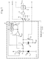
- FIG. 1 Arranged cells in a row or in an array will.
- the cell shown in FIG. 1 has a photodiode 1 trained photosensitive element on the one hand with the earth potential and on the other hand with a current source 2 connected is.
- the potential point P common to the photodiode 1 and the current source 2 is coupled to the input of a controller 3, the output of which is connected to the control input of the current source 2 via two filters 4, 5 connected in parallel, in particular each designed as a low-pass filter, so that the controller 3 ultimately causes the potential point P between the current source 2 and the photodiode 1 to be kept at the potential V ref , which is applied to the second input of the controller 2.
- the first filter 4 has a time constant of 1 kHz and is directly between the output of controller 3 and the control input the power source 2 switched.
- the second filter 5 has a time constant of 50kHz and is also between the output of controller 3 and the control input of Current source 2 switched, but between the output the controller 3 and the input of the filter 5 a controllable Switch 6 is provided.
- the common potential P of the photodiode 1 and the current source 2 is connected via a likewise controllable switch 7 to a pole of a capacitor 8, the other pole of which is at the potential V ref .
- the pole of the switch 7 facing the capacitor 8 is above a further switch 10 with the input of an amplifier 11 coupled, the output of which is the input of a sample and Hold member 12 is supplied.
- the switches 6 and 7 are from a common control input SE applied, i.e. that both switches by the control signal SE can be operated simultaneously, the switch 7 is always open when switch 6 is closed and vice versa.
- switches 10, 10 ', etc. each of which is one in FIG. 1 shown cell is assigned. So if the switches 10, 10 ', etc. can be operated sequentially one after the other sequentially one after the other in the capacitors 8, 8 ', etc. stored values in the sample and hold element shown 12 can be saved.
- Switch 10, 10 ', etc. For sequentially operating the Switch 10, 10 ', etc. is an address and clock line Ad & Cl provided, via which one of the switches 10, 10 ', etc. can be addressed and operated.
- the clock component of the signal Ad & Cl is on as signal Cl the clock input of the sample-and-hold element 12 to clock this accordingly and for timely reading the values stored in the capacitors 8, 8 ', etc. to care.
- a reset line R is provided by means of which on the one hand the switch 9 can be actuated and closed and on the other hand, the sample-and-hold element 12 can be reset.
- the control loop consisting of elements 2-6 is active, filter 5 with the time constant 50 kHz being decisive here.
- the control loop follows rapid changes at the potential point P, which are caused by ambient light via the photodiode 1.
- the control loop explained consequently ensures with a time constant of 50 kHz that the potential point P is kept at the potential V ref regardless of the amplitude and frequency of the ambient light.
- the capacitor 8 is charged to the potential V ref at the switch positions shown in the drawing, ie charge is stored in the capacitor 8.
- the filter 5 is excluded Force set, which means that only the filter 4th is active with a time constant of 1 kHz.
- the one described The control loop thus only follows slow signal changes and causes at the potential point P that before opening the Switch 6 active control only for interference signals with accordingly low frequency is continued.
- the one that takes place immediately before the useful signal reception Closing the switch 7 causes the one through whom Photodiode 1 flowing additional current through the useful light is caused from the capacitor 8 or from the in this capacitor 8 stored charge is obtained.
- the switch is switched on via the signal SE 7 opened again and switch 6 closed.
- the sample and hold element 12 By addressing and loading the switch 10 over the signal Ad & Cl becomes the charge difference mentioned Capacitor 8 via the amplifier 11, the sample and hold element 12 fed where a storage of this difference signal he follows. The one stored in the sample and hold element 12 Value can then be processed in any way.
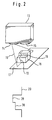
- FIG. 2 shows an optoelectronic sensor arrangement according to the invention 13 housed in a cuboid housing and a transmission optic on one of its long narrow sides 14 and a receiving optics arranged next to this 15 has.
- a light transmitter is provided in the housing behind the transmission optics 14. There is also a behind the receiving optics 15 Light receiver unit with a variety of in a matrix arranged photosensitive elements.
- Light transmitter and transmission optics 14 are designed such that they emit a V-shaped light beam in a plane 16, which extends through the surveillance area towards a level 17 that extends the surveillance area limited on the side facing away from the sensor arrangement 13.
- Level 17 does not necessarily have to be a stationary one, at the end of the monitoring area arranged element, but can also be designed as funding, for example on which objects are transported through the surveillance area will.
- an object 18 which consists of two side by side arranged, different sized cuboids.
- the light beam emitted by the light transmitter is shown in the Embodiment aligned such that it is inclined object 18 hits. It is essential that level 16 of the Transmitting light beam at an angle greater than 0 ° to the optical Axis of the receiving optics 15 runs so that it is also possible would be to hit the transmitted light beam perpendicularly on the object 18 to let and the optical axis of the receiver accordingly to align diagonally.
- the light beam irradiating the object 18 in the manner mentioned creates a light line 19 on the object 18, the so-called Light section.
- this line of light points 19 the course shown in the lower area of FIG. 2 20 on.
- the representation of the course 20 according to FIG. 2 can be seen that this course 20 ultimately the Corresponds to the height profile of the object 18, the area 38 of the course 20 the smaller cuboid of the object 18 and the Area 39 of the course 20 the larger cuboid of the object 18 indicates.
- the height profile in a simple manner using the light section method of an object can be determined, here based on of the principle according to the invention a high level of light immunity is guaranteed.
- the object 18 mentioned in connection with FIG. 2 can also be designed differently.
- it can to be a single object, which has a certain processing state which is recognized according to the invention shall be.
- According to the principle according to the invention e.g. can be recognized whether an object is provided with a milling groove or whether the milling groove has the desired dimensions.
- a typical use case for the detection of multiple objects consists of counting a stream of shingles superimposed newspapers or magazines.
- the difference is made determined from level to level, with fluctuations in the amount of scanned newspapers or magazines that by vibrating the objects transporting said objects Conveyor belts are created by the relative measurement mentioned be compensated.
- relative measurement is used understood that only the stages of the scale flow, i.e. the height differences between two successive, Newspapers or magazines lying on top of each other like shingles be determined.
- FIG. 3 shows a sensor arrangement 21 according to the invention, which like the sensor arrangement 13 according to FIG. 2 in a cuboid Housing is housed.
- the sensor arrangement 21 has an autocollimation optics 22 on which for both the transmit and receive radiation is decisive.
- the sensor arrangement 21 sends a V-shaped light beam 23 towards a reflector 24 which emits the Light reflected back to the sensor arrangement 21.
- the monitoring area is on one side by the reflector 24 and on the other hand through the sensor arrangement 21 limited.
- the band 27 hangs between positions 25 and 26 in such a way that it projects into the area of the light beam 23 and in this way prevents all of light from the sensor arrangement 21 onto the area 28 of the reflector hits. Due to the sagging band 27 strikes only the area 29 of the reflector from the sensor arrangement 21 emitted light, so that even from this area 29 reflects light back to the sensor arrangement 21 becomes.
- the size of the sensor arrangement 21 can of area 29 can be determined, which is ultimately a measure represents for the current sag of the band 27.
- V-shaped described above in connection with Figure 3 Illumination of the band 27 or the reflector 24 can alternatively, advantageously also by means of a telecentric Lighting to be replaced, which essentially only includes light beams directed in parallel.
- the transformation the V-shaped lighting into a telecentric lighting can for example by a concave mirror or a lens can be achieved.
- FIG. 4 shows an optoelectronic sensor arrangement according to the invention 30, which, like the sensor arrangement according to FIG Figures 2 and 3 housed in a cuboid housing is.
- the sensor arrangement 30 sends a light beam 31 in the direction a reflector 32, which the emitted light back to Sensor arrangement 30 reflects.
- the light beam 31 is designed such that the entire area of the reflector 32 is illuminated so that everyone reflective point on the reflector 32 for generation a corresponding signal in the sensor arrangement 30 can lead.
- Photosensitive cells are equipped for differentiation different shades of gray are suitable for example the image of an object according to FIG. 5a on different Types are evaluated:
- 5a has three different bright areas with the area 35 brightest and the area 37 is the darkest.
- the brightness of the area 36 lies between the brightnesses of the two areas 35 and 37.
- a sensor arrangement according to the invention can be programmed in this way or be set so that they only such objects or object areas recognizes which have a brightness that above or below a threshold or between two thresholds lie. This is illustrated by means of FIGS. 5b-d, all from a sensor arrangement according to the invention delivered images of the object according to FIG. 5a show, wherein different operating modes of the sensor arrangement are set.
- An image according to FIG. 5b is delivered, for example, when the sensor arrangement is set such that only those brightness levels of the object lead to image recognition which are below a threshold value S 1 .
- the brightness levels of the object areas 36 and 37 are below the threshold value S 1 , while the brightness of the object area 35 is above this threshold value.
- the ratio of the brightness levels of the areas 35, 36 and 37 to the threshold value S 1 is illustrated by the staircase signal and the threshold value S 1 shown in FIG. 5b.
- the first stage of the staircase signal corresponds to the dark object region 37
- the second stage corresponds to the middle object region 36
- the third stage corresponds to the light object region 35.
- Fig. 5b shows that with the threshold setting mentioned only the object areas 36 and 37 are recognized while reflected from the background and the object area 35 Light does not emit a corresponding light signal leads.
- the image according to FIG. 5b thus only contains the contours of object areas 36 and 37.
- 5c illustrates an operating mode of the sensor according to the invention in which a lower threshold value S 2 is set, so that ultimately only the darkest object area 37 is recognized.
- an operating mode of the sensor according to the invention is also possible in which only those object areas are detected whose brightness lies between the two threshold values S 1 and S 2 .
- the image of the object according to FIG. 5a delivered in such an operating mode is illustrated in FIG. 5d. Only the object area 36 has a brightness that lies between the two threshold values S 1 and S 2 , so that only this object area 36 is also imaged.
Abstract
Description
Die Erfindung betrifft eine opto-elektronische Sensoranordnung mit einem Lichtsender zur Aussendung von aufeinanderfolgenden Nutzlichtimpulsen in einen Überwachungsbereich und einer Lichtempfängereinheit zum Empfang von von einem im Überwachungsbereich befindlichen Objekt reflektierten Nutzlichtimpulsen.The invention relates to an opto-electronic sensor arrangement with a light transmitter for sending successive Useful light pulses in a monitoring area and one Light receiver unit for receiving one in the surveillance area reflected object reflected useful light pulses.
Bei derartigen Sensoranordnungen können die Lichtempfängereinheiten beispielsweise mehrere photoempfindliche Elemente umfassen, so daß nach einer geeigneten Auswertung der von den photoempfindlichen Elementen gelieferten Signale auf die Position des reflektierenden Objektes im Überwachungsbereich geschlossen werden kann.With such sensor arrangements, the light receiver units can for example several photosensitive elements include, so that after a suitable evaluation of the Photosensitive elements delivered signals to the position of the reflecting object in the surveillance area can be closed.
Diese Sensoranordnungen sind aus dem Stand der Technik als PSDs (positionssensitive Detektoren) oder als beispielsweise in Videokameras verwendete CCDs bekannt und besitzen den ihnen gemeinsamen Nachteil, daß lediglich eine unzureichende Fremdlicht-, insbesondere Gleichlichtfilterung möglich ist. PSDs erlauben aufgrund einer bereits früh eintretenden Sättigung lediglich eine beschränkte Fremdlichtfilterung, CCDs ermöglichen lediglich die Beseitigung von Fremdlicht, insbesondere Gleichlicht durch eine nach dem eigentlichen Lichtempfang stattfindenden Subtraktion eines Fremdlichtwerts, welcher über alle photoempfindlichen Elemente gemittelt ist. Zudem ist es bei PSDs von Nachteil, daß zu einem bestimmten Zeitpunkt immer nur ein einziges Objekt erkannt werden kann.These sensor arrangements are known from the prior art PSDs (position sensitive detectors) or as for example CCDs used in video cameras are known and own them common disadvantage that only an insufficient Extraneous light, in particular constant light filtering is possible. PSDs allow due to early saturation only limited extraneous light filtering, CCDs enable only the removal of extraneous light, in particular Constant light through after the actual light reception subtraction of an extraneous light value, which is averaged over all photosensitive elements. In addition it is disadvantageous with PSDs that to a certain Only one object can be recognized at a time.
Aufgrund der vorstehend beschriebenen Nachteile eignen sich aus dem Stand der Technik bekannte Sensoren nur sehr beschränkt für den Industrieeinsatz, bei dem beispielsweise eine wirksame und zuverlässige Unterdrückung von Fremdlicht, welches in Industrieanwendungen mit einer erheblichen Signaldynamik auftritt, zwingend erforderlich ist.Because of the disadvantages described above are suitable Sensors known from the prior art are only very limited for industrial use, where for example a effective and reliable suppression of extraneous light, which in industrial applications with significant signal dynamics occurs, is absolutely necessary.
Eine Aufgabe der Erfindung besteht darin, eine opto-elektronischen Sensoranordnung der eingangs genannten Art derart weiterzubilden, daß eine verbesserte Fremdlicht-, insbesondere Gleichlichtunterdrückung ermöglicht wird.An object of the invention is an opto-electronic Sensor arrangement of the type mentioned to further develop such that an improved extraneous light, in particular Constant light suppression is made possible.
Erfindungsgemäß wird diese Aufgabe dadurch gelöst, daß bei einer opto-elektronischen Sensoranordnung der genannten Art, bei der die Lichtempfängereinheit zumindest zwei photoempfindliche Elemente umfaßt, jedem photoempfindlichen Element jeweils eine Schaltung zur Fremdlichtunterdruckung zugeordnet wird. Erfindungsgemäß ist somit jedes photoempfindliche Element mit einer eigenen, separaten Fremdlichtunterdrückungs-Schaltung ausgerüstet.According to the invention this object is achieved in that an opto-electronic sensor arrangement of the type mentioned, in which the light receiver unit has at least two photosensitive Elements, each photosensitive element each assigned a circuit for extraneous light suppression becomes. Each photosensitive element is thus in accordance with the invention with its own separate extraneous light suppression circuit equipped.
Das erfindungsgemäße Prinzip ermöglicht eine besonders zuverlässige und effektive Fremdlichtunterdrückung, die beispielsweise auch dann eine sichere Nutzlichtsignalerkennung ermöglicht, wenn der Dynamikbereich des Nutzlichtsignals deutlich kleiner als der Dynamikbereich des Fremdlichts ist. Insbesondere ist es erfindungsgemäß beispielsweise möglich, bei einem Fremdlicht-Dynamikbereich von 107 Nutzlichtsignale mit einem vergleichsweise geringem Dynamikbereich von beispielsweise bis zu 103 zuverlässig zu erkennen. Dies ist auch dann möglich, wenn das Fremdlicht Amplituden aufweist, die mehrere Zehner-Dekaden über den Amplituden des Nutzlichts liegen.The principle according to the invention enables particularly reliable and effective suppression of extraneous light, which, for example, also enables reliable detection of useful light signals when the dynamic range of the useful light signal is significantly smaller than the dynamic range of the extraneous light. In particular, according to the invention it is possible, for example, to reliably identify useful light signals with a comparatively small dynamic range of up to 10 3, for example, with an external light dynamic range of 10 7 . This is also possible if the extraneous light has amplitudes that are several tens of decades above the amplitudes of the useful light.
Weiterhin ist es bei der erfindungsgemäßen opto-elektronischen Sensoranordnung vorteilhaft, daß aufgrund der in jeder Zelle einer Zeile oder eines Arrays bzw. bezüglich jeden photoempfindlichen Elements getrennt stattfindenden Fremdlichtunterdrückung unterschiedlich beleuchtete Hintergrundflächen keinerlei negative Auswirkungen auf die Nutzlichtsignalauswertung haben. Das empfangene Nutzlicht gibt erfindungsgemäß immer korrekt Aufschluß über die Reflektivität von Objekten oder Hintergrundelementen im Überwachungsbereich, unabhängig davon, in welcher Weise diese Objekte bzw. Hintergrundelemente durch Fremdlicht beleuchtet werden. Wenn also beispielsweise ein Objekt im Überwachungsbereich vorhanden ist und das von der erfindungsgemäßen opto-elektronischen Sensoranordnung ausgesandte Licht von einer Hintergrundfläche mit gleichmäßiger, homogener Reflektivität reflektiert wird, liefert die Hintergrundfläche auch dann ein konstantes, ihre homogene Reflektivität repräsentierendes Empfangssignal, wenn bestimmte Bereiche der Hintergrundfläche stärker durch Fremdlicht bestrahlt werden als andere Bereiche. Inhomogene Beleuchtungen der Hintergrundfläche werden somit erfindungsgemäß neutralisiert.Furthermore, it is the opto-electronic according to the invention Sensor arrangement advantageous that due to the in each Cell of a row or an array or with respect to each photosensitive Elements separate suppression of extraneous light differently illuminated background areas no negative effects on the useful light signal evaluation to have. The received useful light gives according to the invention always correct information about the reflectivity of objects or background elements in the surveillance area, independently of how these objects or background elements be illuminated by extraneous light. So if, for example there is an object in the surveillance area and that from the opto-electronic sensor arrangement according to the invention emitted light from a background surface with uniform, homogeneous reflectivity is reflected, provides the Background area even then a constant, its homogeneous reflectivity representative received signal when certain Areas of the background area are more strongly exposed to extraneous light than other areas. Inhomogeneous lighting the background area are thus neutralized according to the invention.
Die Fremdlichtunterdrückung bei einem erfindungsgemäßen opto-elektronischen Sensor läßt sich zusätzlich dadurch verbessern, daß nur relativ kurze Nutzlichtimpulse, insbesondere solche mit hoher Energie, ausgesandt werden. Die Dauer der Nutzlichtimpulse kann dabei beispielsweise im ns-Bereich liegen.The suppression of extraneous light in an opto-electronic according to the invention The sensor can also be improved by that only relatively short useful light pulses, in particular those with high energy. The duration of the Useful light pulses can be in the ns range, for example.
Die Pulsdauer des Nutzlichtsignals kann vorzugsweise zwischen 1µs und 20µs betragen. Von Vorteil ist es, wenn der Kehrwert der Pulsdauer des Nutzlichts ungefähr um zwei Größenordnungen über der höchsten vorkommenden Störlichtfrequenz liegt, da dann eine besonders zuverlässige Stör- bzw. Fremdlichtunterdrückung möglich wird.The pulse duration of the useful light signal can preferably be between 1µs and 20µs. It is advantageous if the reciprocal the pulse duration of the useful light by approximately two orders of magnitude lies above the highest occurring stray light frequency, because then a particularly reliable interference or external light suppression becomes possible.
Aufgrund der erfindungsgemäßen Fremdlichtunterdrückung wird es möglich, anstelle eines aus dem Stand der Technik bekannten logarithmischen Übertragungsverhaltens des Sensors ein lineares Übertragungsverhalten vorzusehen, d.h., der von den erfindungsgemäßen photoempfindlichen Elementen gelieferte Nutzlicht-Empfangsstrom kann einen zum Reflexions- oder Remissionsgrad der im Überwachungsbereich befindlichen Objekte und Elemente proportionalen Verlauf aufweisen.Due to the extraneous light suppression according to the invention it is possible instead of one known from the prior art logarithmic transmission behavior of the sensor linear transmission behavior, i.e. that of the supplied photosensitive elements according to the invention Useful light reception current can be a reflection or reflectance of the objects in the surveillance area and elements have a proportional course.
Besonders vorteilhaft ist der Einsatz einer erfindungsgemäßen Sensoranordnung dann, wenn eine Vielzahl von photoempfindlichen Elementen nebeneinander in Zeilenanordnung oder Matrixanordnung vorgesehen werden. Insbesondere bei einer Matrixanordnung wird es erfindungsgemäß möglich, nicht nur das Vorhandensein eines Objektes im Überwachungsraum sondern auch dessen Position zu ermitteln.The use of a device according to the invention is particularly advantageous Sensor arrangement when a variety of photosensitive Elements side by side in a row or matrix arrangement be provided. Especially with a matrix arrangement it is possible according to the invention, not only that Presence of an object in the surveillance room but also to determine its position.
In einer bevorzugten Ausführungsform der Erfindung weist jede der Schaltungen zur Fremdlichtunterdrückung eine mit dem jeweiligen photoempfindlichen Element verbundene geregelte Energiequelle, insbesondere eine Stromquelle auf. Diese Energiequelle liefert dabei den durch das photoempfindliche Element fließenden Strom, welcher in den Pausen zwischen den Nutzlichtimpulsaussendungen dem vorhandenen Fremdlicht entspricht. Der von der genannten Energiequelle gelieferte Strom wird dann erfindungsgemäß auch während der Nutzlichtsignalaussendung auf demjenigen Wert gehalten, der dem zuletzt ermittelten oder dem in den Zeitbereich einer Nutzlichtsignalaussendung extrapolierten Fremdlichtverlauf entspricht.In a preferred embodiment of the invention, each of the circuits for suppression of extraneous light one with the respective Regulated photosensitive element Energy source, especially a power source. This energy source provides the through the photosensitive element flowing current, which in the breaks between the Useful light pulse emissions correspond to the existing ambient light. The electricity supplied by the named energy source is then according to the invention also during the transmission of useful light signals kept at the value determined last or in the time range of a useful light signal transmission extrapolated extraneous light curve corresponds.
Der beim Empfang von Nutzlicht zusätzlich durch das photoempfindliche Element fließende Strom wird aus einer anderen Energiequelle, insbesondere einem Kondensator bezogen, wobei der meßbare Wert dieses zusätzlichen Stroms dann letztlich dem empfangenen Nutzlicht entspricht.The additional when receiving useful light through the photosensitive Element flowing current becomes another Energy source, in particular related to a capacitor, wherein the measurable value of this additional current ultimately corresponds to the received useful light.
Um das genannte Prinzip der Nutzsignalermittlung zu realisieren, kann die Regelung der Energiequelle in den Pausen zwischen der Aussendung der Nutzlichtimpulse zuschaltbar und während der Aussendung der Nutzlichtimpulse abschaltbar sein. In order to implement the above-mentioned principle of useful signal determination, can regulate the energy source in the breaks between the transmission of the useful light pulses can be activated and can be switched off during the transmission of the useful light pulses.
Ebenso ist es jedoch auch möglich, die Regelung in Zeiten der
Aussendung der Nutzlichtimpulse gegenüber der Regelung in den
Pausen zwischen der Aussendung der Nutzlichtimpulse veränderbar
auszuführen, wobei die Änderung des Regelverhaltens insbesondere
durch Aktivierung und Deaktivierung zumindest eines
Filters eines Regelkreises bewirkbar ist. Dabei kann in den
Pausen zwischen der Aussendung der Nutzlichtimpulse ein Filter
mit kürzerer Zeitkonstante aktivierbar sein als während
der Aussendung der Nutzlichtimpulse.
Durch die letztgenannte Vorgehensweise kann während der
Aussendung der Nutzlichtimpulse eine Extrapolation des von
der Energiequelle gelieferten Stromes in Abhängigkeit von
dessen Verlauf in den Pausen zwischen der Nutzlichtaussendung
erreicht werden, so daß die Fremdlichtkompensation zusätzlich
verbessert wird.Likewise, however, it is also possible to make the regulation changeable in times of the transmission of the useful light pulses compared to the regulation in the pauses between the transmission of the useful light pulses, the change in the regulating behavior being able to be effected in particular by activating and deactivating at least one filter of a regulating circuit. A filter with a shorter time constant can be activated in the pauses between the transmission of the useful light pulses than during the transmission of the useful light pulses.
The latter procedure allows extrapolation of the current supplied by the energy source as a function of its course in the pauses between the transmission of useful light during the transmission of the useful light pulses, so that the external light compensation is additionally improved.
Jede der Schaltungen zur Fremdlichtunterdrückung kann mit einem Speicherelement zur Speicherung des vom photoempfindlichen Element empfangenen Nutzlichtanteils versehen werden, wobei das Speicherelement insbesondere als Kondensator ausgeführt wird.Each of the circuits for extraneous light suppression can be equipped with a Storage element for storing the photosensitive Element received useful light portion are provided, the storage element being designed in particular as a capacitor becomes.
Während des Nutzlichtimpuls-Empfangs kann das Speicherelement über einen Schalter mit dem photoempfindlichen Element koppelbar sein, so daß die Amplitude des empfangenen Nutzlichts in das Speicherelement übertragen wird.The memory element can be received during the useful light pulse reception can be coupled to the photosensitive element via a switch be so that the amplitude of the received useful light is transferred into the storage element.
Von Vorteil ist es, wenn alle Speicherelemente gleichzeitig mit den ihnen jeweils zugeordneten photoempfindlichen Elementen koppelbar sind, so daß auch schnelle Bewegungen von Objekten im Überwachungsbereich korrekt erfaßbar sind. Die genannte gleichzeitige Kopplung der Speicherelemente mit den photoempfindlichen Elementen ermöglicht somit korrekte und von Fremdlicht bereinigte Momentaufnahmen des Überwachungsbereichs. It is advantageous if all storage elements at the same time with the photosensitive elements assigned to them can be coupled so that even fast movements of objects are correctly detectable in the surveillance area. The said simultaneous coupling of the storage elements with the Photosensitive elements thus enables correct and Snapshots of the surveillance area cleaned of extraneous light.
Um eine ständige Überwachung des Überwachungsbereichs zu ermöglichen und in kurzen Zeitabständen aufeinanderfolgende Momentaufnahmen des Überwachungsbereichs verfügbar zu machen, kann das Speicherelement jeder der vorgesehenen Schaltungen zur Fremdlichtunterdrückung mit einer während der Pause zwischen der Aussendung der Nutzlichtimpulse aktivierbaren Rücksetzschaltung gekoppelt sein. So können alle vorhandenen Speicherelemente nach einer erfolgten Momentaufnahme und nachdem die gespeicherten Werte einer Auswerteschaltung zur Verfügung gestellt wurden, wieder auf einen neutralen Wert zurückgesetzt und somit für die Speicherung eines neuen Nutzlichtsignalwerts bereit gemacht werden.To enable constant surveillance of the surveillance area and consecutive snapshots at short intervals make the surveillance area available, can the memory element of each of the circuits provided for suppression of extraneous light with a during the break between the transmission of the useful light pulses activatable reset circuit be coupled. So all existing ones Storage elements after a snapshot and after the stored values of an evaluation circuit for Were made available again to a neutral value reset and thus for the storage of a new useful light signal value be made ready.
Die vorgesehenen Speicherelemente können über einen insbesondere adressierbaren Schalter mit einem oder mehreren Sample-und-Hold-Gliedern, einer Komparatorschaltung oder einem A/D-Wandler verbunden sein.The storage elements provided can in particular have a addressable switch with one or more sample-and-hold elements, a comparator circuit or an A / D converter be connected.
Bei Übertragung des in den Speicherelementen gespeicherten Werts in ein Sample-und-Hold-Glied wird auf vorteilhafte Weise erreicht, daß die mit der Sensoranordnung ermittelten Informationen über den Überwachungsbereich zeitunkritisch ausgelesen und ausgewertet werden können. Insbesondere ist eine Weiterverarbeitung eines in einem Sample-und-Hold-Glied gespeicherten Wertes möglich, während in den Speicherelementen jeweils bereits wieder neue Werte gespeichert werden.When transferring the stored in the storage elements Value in a sample-and-hold link is beneficial achieved that the information determined with the sensor arrangement read out non-time-critical over the monitoring area and can be evaluated. One is in particular Further processing of one stored in a sample-and-hold element Value possible while in the storage elements new values are already saved in each case.
Bei Vorsehung von geeigneten Komparatorschaltungen oder einem A/D-Wandler, denen die Werte der Speicherelemente zugeführt werden, ist es möglich, auch eine Aussage über die Amplitude der in den Speicherelementen gespeicherten Werte und somit über Grauwerte eines Bildes zu treffen, das mit einer erfindungsgemäßen Sensoranordnung beispielsweise mit einer Momentaufnahme der genannten Art erfaßt wurde. Die Auflösung der Grauwerte kann dabei an die jeweiligen Anforderungen angepaßt werden, beispielsweise ist es in bestimmten Fällen ohne weiteres möglich, die in den Speicherelementen gespeicherten, eine Vielzahl von verschiedenen Amplituden aufweisenden Werte im Rahmen einer Datenreduktion auf einige wenige, für den jeweiligen Anwendungsfall prägnante Graustufen zu reduzieren.With the provision of suitable comparator circuits or a A / D converter, to which the values of the memory elements are fed be, it is also possible to make a statement about the amplitude of the values stored in the storage elements and thus about gray values of an image to be taken with an image according to the invention Sensor arrangement, for example with a snapshot of the type mentioned was recorded. The dissolution of the Gray values can be adapted to the respective requirements , for example, in certain cases it is straightforward possible, the stored in the storage elements, a variety of different amplitude values as part of a data reduction to a few, for each Use case to reduce concise grayscale.
Bei Einsatz einer Komparatorschaltung ist es von Vorteil, wenn diese einen verstellbaren Schwellwert aufweist, da auf diese Weise erreicht werden kann, daß der Schwellwert, welcher letztlich dafür maßgeblich ist, ab welcher empfangenen Lichtmenge tatsächlich ein Lichtempfang signalisiert wird, an die jeweils gegebenen Verhältnisse angepaßt werden kann. Insbesondere ist es in diesem Fall möglich, im Rahmen eines vor der eigentlichen Messung stattfindenden Teachvorganges den Schwellwert des Komparators an die jeweils gegebenen Kontrastverhältnisse anzupassen. Durch die Vorsehung des verstellbaren Schwellwerts und die Einschaltung eines Teachvorganges kann auf vorteilhafte Weise der Einsatz eines A/D-Wandlers eingespart werden, was überdies zu einer maximalen Datenreduktion auf lediglich zwei Werte (Lichtempfang ja/Lichtempfang nein) führt.When using a comparator circuit, it is advantageous if this has an adjustable threshold, because on this way it can be achieved that the threshold which Ultimately, it is decisive from which received Amount of light is actually signaled to receive light the given conditions can be adjusted. Especially in this case it is possible to do so in the context of a the actual measurement of the teaching process Threshold value of the comparator to the given contrast ratios adapt. By providing the adjustable Threshold and the activation of a teaching process can advantageously use an A / D converter be saved, which moreover leads to a maximum Data reduction to just two values (light reception yes / light reception no) leads.
Ein besonders wirtschaftlicher Einsatz einer erfindungsgemäßen Sensoranordnung wird möglich, wenn alle photoempfindlichen Elemente der Lichtempfängereinheit auf einem einzigen Chip angeordnet werden. Ebenso können alle Schaltungen zur Fremdlichtunterdrückung ebenfalls auf dem genannten Chip angeordnet werden, so daß die gesamte erfindungsgemäße Sensoranordnung auf einen einzigen Chip integrierbar ist.A particularly economical use of an inventive Sensor arrangement becomes possible when all photosensitive Elements of the light receiver unit on a single Chip are arranged. Likewise, all circuits for Suppression of extraneous light is also arranged on the chip mentioned be so that the entire sensor assembly according to the invention can be integrated on a single chip.
Die photoempfindlichen Elemente der Lichtempfängereinheit können äquidistant voneinander beabstandet oder direkt aneinander angrenzend angeordnet werden. Es können somit geometrische Verhältnisse erreicht werden, die denen von CCD-Arrays entsprechen, wobei sowohl große als auch kleine Empfängergrößen, d.h. photoempfindliche Elemente mit großen und kleinen Empfangsflächen realisierbar sind. Insbesondere ist es möglich, die photoempfindlichen Elemente so dicht beieinander anzuordnen, daß sich eine photoempfindliche Fläche mit nahezu 100% Füllgrad ergibt.The photosensitive elements of the light receiver unit can be equidistant from each other or directly next to each other be arranged adjacent. It can therefore be geometric Ratios can be achieved that of CCD arrays correspond with both large and small receiver sizes, i.e. photosensitive elements with large and small Reception areas are realizable. In particular, it is possible the photosensitive elements so close together to arrange that a photosensitive surface with almost 100% fill level results.
Die photoempfindlichen Flächen der vorgesehen Elemente können unterschiedliche geometrische Formen aufweisen, wobei die Form an die jeweils gegebenen Anforderungen anpaßbar ist.The photosensitive surfaces of the elements provided can have different geometric shapes, the Form is adaptable to the given requirements.
Schließlich ist es auch möglich, den photoempfindlichen Elementen jeweils Farbfilter, insbesondere in ihrer Durchlaßfrequenz verstellbare Farbfilter vorzuschalten. Auf diese Weise kann die erfindungsgemäße Sensoranordnung auch als mehrdimensionales Farberkennungssystem genutzt werden.Finally, it is also possible to use the photosensitive elements each color filter, especially in its pass frequency adjustable color filters. In this way the sensor arrangement according to the invention can also be a multi-dimensional one Color detection system can be used.
Um eine zuverlässige Farberkennung zu ermöglichen, können
beispielsweise immer drei aneinander angrenzende photoempfindliche
Elemente mit unterschiedlichen Farbfiltern versehen
werden, so daß immer jeweils eine Einheit von drei photoempfindlichen
Elementen zur Erkennung eines Farbpixels geeignet
ist.
Alternativ ist es auch möglich, allen photoempfindlichen Elementen
jeweils einen verstellbaren Farbfilter vorzuschalten,
Wo daß in kurz aufeinanderfolgenden Zeitabständen beispielsweise
drei Momentaufnahmen des Überwachungsbereichs mit jeweils
unterschiedlich eingestellten Farbfiltern aufgenommen
werden, wobei diese drei Momentaufnahmen dann zu einem Farbbild
zusammensetzbar sind.In order to enable reliable color detection, for example, three adjacent photosensitive elements can always be provided with different color filters, so that a unit of three photosensitive elements is always suitable for detecting a color pixel.
Alternatively, it is also possible to connect an adjustable color filter upstream of all photosensitive elements, where that, for example, three snapshots of the surveillance area are taken in short succession with differently set color filters, these three snapshots then being able to be combined to form a color image.
Die Erfindung umfaßt auch eine solche Ausführungsform, bei der die Lichtempfängereinheit lediglich ein photoempfindliches Element umfaßt, dem eine Schaltung zur Fremdlichtunterdrückung zugeordnet ist, die konkret entsprechend den vorstehend beschriebenen Merkmalen ausgebildet ist oder die der im Rahmen der nachfolgenden Figurenbeschreibung erläuterten Schaltung entspricht.The invention also includes such an embodiment which the light receiver unit is only a photosensitive Element comprises a circuit for suppression of extraneous light is assigned, which corresponds specifically to the above described features is formed or the in Explained within the scope of the following description of the figures Circuit corresponds.
Bei einem vorteilhaften Verfahren zum Betrieb einer opto-elektronischen Sensoranordnung der beschriebenen Art wird mittels einer Auswerteschaltung beispielsweise die Position, die Bewegung, das Höhenprofil einschließlich eventueller schräger Flanken und/oder der Kontrast eines im Überwachungsbereich befindlichen Objekts ermittelt. Eine Auswerteschaltung, die dazu in der Lage ist, eine oder mehrere der vorstehend genannten Funktionen zu verwirklichen, ermöglicht vielfältige Einsatzmöglichkeiten der erfindungsgemäßen Sensoranordnung. Von Vorteil ist es, wenn die Auswerteschaltung mehrere Funktionen realisieren kann, zwischen denen der Benutzer der Sensoranordnung umschalten kann, ohne daß hierfür eine Neuprogrammierung der Sensoranordnung erforderlich wäre. Diese Umschaltfunktion kann insbesondere durch einen Wahl-Schalter realisiert werden.In an advantageous method for operating an opto-electronic Sensor arrangement of the type described by means of an evaluation circuit, for example, the position, the movement, the height profile including any sloping flanks and / or the contrast of one in the surveillance area located object determined. An evaluation circuit which is capable of one or more of the above Realizing the mentioned functions enables a variety of functions Possible uses of the sensor arrangement according to the invention. It is advantageous if the evaluation circuit has several Can implement functions between which the user the sensor arrangement can switch without this Reprogramming the sensor arrangement would be necessary. This Switching function can in particular by a selector switch will be realized.
Bei Ermittlung der Position, der Bewegung, des Höhenprofils oder des Kontrastes eines Objektes mittels der erfindungsgemäßen Sensoranordnung ist es von Vorteil, wenn das jeweilige Objekt aktiv, insbesondere mit definierter Lichtstärke beleuchtet wird, da auf diese Weise eine sichere Erkennung und fehlerfreie Auswertung sichergestellt werden kann.When determining the position, the movement, the height profile or the contrast of an object by means of the invention Sensor arrangement, it is advantageous if the respective Object active, especially illuminated with a defined light intensity is because in this way a reliable detection and error-free evaluation can be ensured.
In diesem Zusammenhang wird darauf hingewiesen, daß die Sensoranordnung prinzipiell auch ohne aktiven Lichtsender betrieben werden kann, wobei in diesem Fall Fremd- bzw. Umgebungslicht vom im Überwachungsbereich befindlichen Objekt zur Lichtempfängereinheit reflektiert wird oder das Objekt selbst als Lichtquelle ausgebildet ist. Fremd- bzw. Umgebungslicht sollten in diesem Fall jedoch die erforderliche Zeitsynchronisation besitzen. Die Lichtempfängereinheit umfaßt auch bei dieser Anwendungsmöglichkeit zumindest zwei photoempfindliche Elemente, wobei jedem photoempfindlichen Element jeweils eine Schaltung zur Fremdlichtunterdrückung zugeordnet ist.In this context, it is pointed out that the sensor arrangement in principle also operated without an active light transmitter can be, in which case extraneous or ambient light from the object in the surveillance area to Light receiving unit is reflected or the object itself is designed as a light source. External or ambient light in this case, however, the required time synchronization have. The light receiver unit also includes this application, at least two photosensitive Elements, each having a photosensitive element Circuit for extraneous light suppression is assigned.
Es sind zwei mögliche Einsatzfälle einer mit aktivem Lichtsender
betriebenen erfindungsgemäßen Sensoranordnung zu unterscheiden.
Bei einem ersten Einsatzfall wird am der Sensoranordnung gegenüberliegenden
Ende des Überwachungsbereichs ein den Überwachungsbereich
begrenzender Reflektor vorgesehen, welcher
dazu dient, vom Lichtsender der Sensoranordnung ausgesandtes
Licht zurück zum Empfänger zu reflektieren. Dies ist beispielsweise
bei großen Entfernungen sinnvoll, bei denen sichergestellt
werden muß, daß ausreichend Licht zurück zum
Empfänger reflektiert wird.
Bei einem zweiten Einsatzfall wird am der Sensoranordnung gegenüberliegenden
Ende des Überwachungsbereichs kein den Überwachungsbereich
begrenzender Reflektor vorgesehen, was beispielsweise
bei kurzen Entfernungen oder dann, wenn ein zu
erkennendes Objekt ausreichende Reflexionseigenschaften aufweist,
sinnvoll ist.There are two possible applications of a sensor arrangement according to the invention operated with an active light transmitter.
In a first application, a reflector delimiting the monitoring area is provided at the end of the monitoring area opposite the sensor device, which reflector serves to reflect light emitted by the light transmitter of the sensor device back to the receiver. This is useful, for example, at long distances, where it must be ensured that sufficient light is reflected back to the receiver.
In a second application, no reflector delimiting the monitoring area is provided at the end of the monitoring area opposite the sensor arrangement, which is useful, for example, at short distances or when an object to be detected has sufficient reflection properties.
Bei Einsatz des vorstehend erwähnten Reflektors ist es sinnvoll, vor Inbetriebnahme der Sensoranordnung den Reflektor bei objektfreiem Überwachungsbereich derart zu verschwenken und/oder verschieben, bis alle photoempfindlichen Elemente der Lichtempfängereinheit einen Lichtempfang signalisieren. Durch diese Ausrichtung des Reflektors wird erreicht, daß immer dann, wenn bei Betrieb der Sensoranordnung alle photoempfindlichen Objekte einen Lichtempfang signalisieren, davon ausgegangen werden kann, daß sich kein Objekt im Überwachungsbereich befindet. Wenn ein Objekt in den Überwachungsbereich eingebracht wird, verhindert dieses, daß ein Teil der vom Lichtsender ausgesandten Strahlung zum Reflektor gelangt und somit auch nicht zurück zur Lichtempfängereinheit reflektiert werden kann. Ebenso können in den Überwachungsbereich eingebrachte durchscheinende oder transparente Objekte eine Strahlungsdämpfung bewirken. Die entsprechenden photoempfindlichen Elemente der Lichtempfängereinheit werden dann keinen oder einen geringeren Lichtempfang signalisieren, wodurch auf das Vorhandensein eines Objektes im Überwachungsbereich und insbesondere auch auf dessen Position geschlossen werden kann.When using the above-mentioned reflector, it makes sense to the reflector before putting the sensor assembly into operation to pivot in such a way in the case of an object-free surveillance area and / or move until all photosensitive elements signal light reception to the light receiver unit. This alignment of the reflector ensures that always then when all photosensitive during operation of the sensor arrangement Objects signal light reception, of which it can be assumed that there is no object in the surveillance area located. If an object in the surveillance area is introduced, this prevents part of the radiation emitted by the light transmitter reaches the reflector and therefore not reflected back to the light receiver unit can be. Likewise, in the surveillance area introduced translucent or transparent objects Cause radiation attenuation. The corresponding photosensitive Elements of the light receiver unit then do not become or signal less light reception, causing on the presence of an object in the surveillance area and in particular also be closed on its position can.
Das erfindungsgemäße Prinzip kann beispielsweise in einem Sensor nach dem Lichtschnittverfahren eingesetzt werden, um das Vorhandensein, die Position, die Höhe oder das Gesamtprofil eines Objektes zu bestimmen. Dabei wird der Lichtsender der Sensoranordnung derart betrieben, daß er beispielsweise ein im wesentlichen in einer Ebene liegendes V-förmiges Lichtbündel aussendet, welches eine reflektierende Linie auf der Oberfläche eines im Überwachungsbereich vorhandenen Objektes, den sogenannten Lichtschnitt, erzeugt.The principle of the invention can, for example, in one Sensor can be used according to the light section method the presence, position, height or overall profile to determine an object. The light transmitter the sensor arrangement operated such that it, for example a substantially V-shaped plane Beam of light that emits a reflective line the surface of an object in the surveillance area, the so-called light section.
Weiterhin ist es möglich, mit dem erfindungsgemäßen Prinzip eine Durchhangregelung eines flexiblen Objektes, beispielsweise eines Fadens oder eines Bandes zu regeln, indem der durchhängende Bereich des flexiblen Objektes in den Überwachungsbereich der Sensoranordnung eingebracht wird.Furthermore, it is possible with the principle according to the invention sag control of a flexible object, for example to regulate a thread or a tape by the sagging area of the flexible object in the surveillance area the sensor arrangement is introduced.
Weiterhin kann das erfindungsgemäße Prinzip dazu verwendet werden, Kanten von Objekten, Linien, den Abstand bzw. Lücken zwischen zwei Objekten oder die Breite, die Länge oder die Größe eines Objektes zu ermitteln. Die Objekte können sich dabei insbesondere auf einem sie transportierenden Fördermittel befinden. Der Einsatz des erfindungsgemäßen Prinzips führt dabei auf vorteilhafte Weise zu einer schnellen Auswertemöglichkeit, zur Möglichkeit der wählbaren Einstellung von Erkennungs- und Toleranzbereichen, zur Möglichkeit der Detektion geringer Kontrastunterschiede, insbesondere mittels Teach-in-Verfahren, sowie zur Möglichkeit der Erkennung kleiner Objekte, Linien oder Lücken.Furthermore, the principle according to the invention can be used for this edges of objects, lines, the distance or gaps between two objects or the width, the length or the To determine the size of an object. The objects can in particular on a means of transport that transports them are located. The use of the principle according to the invention advantageously leads to a quick evaluation option, on the possibility of the selectable setting of Detection and tolerance ranges, for the possibility of detection low contrast differences, especially by means of Teach-in procedure, as well as the possibility of recognizing smaller ones Objects, lines or gaps.
Zudem ist es möglich, das erfindungsgemäße Prinzip einzusetzen, um einen stationären Zustand, insbesondere die Position von einem oder mehreren Objekten zu überwachen, wobei ein Warnsignal immer dann abgeben wird, wenn die Position eines Objektes außerhalb eines vorbestimmten Toleranzbereiches liegt.It is also possible to use the principle according to the invention to a steady state, especially the position to monitor one or more objects, one Warning signal is always given when the position of a Object outside a predetermined tolerance range lies.
Es ist auch möglich, das erfindungsgemäße Prinzip zur Erkennung von einem oder mehreren Objekten oder Objektmerkmalen anhand ihrer Reflektivität, Ihrer Form, Ihrer Abmessungen und/oder Ihrer Kontur zu verwenden.It is also possible to use the principle according to the invention for detection of one or more objects or object features based on their reflectivity, their shape, their dimensions and / or to use your contour.
Auch transparentes Material kann gemäß dem erfindungsgemäßen Prinzip insbesondere mit Licht überwacht werden. Wenn beispielsweise im Rahmen einer Durchhangregelung transparentes Material überwacht wird, bedingt die untere Kante des durchhängenden Materials in Lichtausbreitungsrichtung eine gewisse Wegstrecke, die sowohl vom ausgesandten als auch vom reflektierten Licht durchlaufen werden muß. Somit ist in diesem Bereich der unteren Kante eine größere Absorption bzw. Reflexion gegeben als beim restlichen durchhängenden Material bzw. bei dem unterhalb des durchhängenden Materials befindlichen Bereich. Folglich wird im Bereich der genannten Kante weniger Licht zum Lichtempfänger reflektiert als in den übrigen Bereichen, wodurch die untere Kante des durchhängenden Materials mittels des erfindungsgemäßen Prinzips detektiert werden kann.Transparent material can also be used according to the invention Principle can be monitored especially with light. If, for example as part of a slack regulation Material is monitored, causing the lower edge of the sagging Material in the direction of light propagation a certain Path that is emitted as well as reflected Light must be passed through. So in this area greater absorption or reflection at the lower edge given than with the remaining sagging material or the one below the sagging material Area. As a result, less becomes in the area of said edge Light reflected to the light receiver than in the other areas, causing the lower edge of the sagging material can be detected by means of the principle according to the invention can.
Analog kann vorgegangen werden, wenn beispielsweise transparente Flaschen erfaßt werden sollen. Auch hier wird das Licht beim im wesentlichen radialen Durchtreten durch die Flaschenwände an der Außenseite der Flaschen sowohl beim Aussenden als auch beim Reflektieren des Lichts eine relativ lange Wegstrecke im transparenten Material zurücklegen, so daß auch hier eine größere Absorption bzw. Reflexion des Lichtes stattfindet als in den restlichen Flaschenbereichen bzw. denjenigen Bereichen, in denen keinerlei Flaschen vorhanden sind. Erfindungsgemäß sind also die Außenseiten bzw. die "Kanten" der Flaschen detektierbar.The same can be done if, for example, transparent Bottles to be captured. Here too the light when passing essentially radially through the bottle walls on the outside of the bottles both when sending out as well as when reflecting the light a relatively long distance put back in transparent material so that too here a greater absorption or reflection of the light takes place as in the remaining bottle areas or those Areas where there are no bottles are. According to the invention, the outer sides or Detectable "edges" of the bottles.
Die Anwendung des erfindungsgemäßen Prinzips ist insbesondere dann vorteilhaft, wenn der Lichtsender mit unterschiedlichen Wellenlängen bzw. unterschiedlichen Farben arbeiten kann, so daß beispielsweise im Rahmen eines Teach-In-Verfahrens die optimale Wellenlänge für eine Kontrasterkennung, eine Kantenerkennung, eine Objekterkennung oder sonstige Detektionsvorgänge einlernbar ist.The application of the principle according to the invention is in particular then advantageous if the light transmitter with different Wavelengths or different colors can work, so that, for example, as part of a teach-in process optimal wavelength for contrast detection, edge detection, object detection or other detection processes is teachable.
Schließlich kann das erfindungsgemäße Prinzip auch zur Erkennung eines ein- oder zweidimensionalen Codes, insbesondere eines Barcodes oder einer Schrift verwendet werden.Finally, the principle according to the invention can also be used for detection a one- or two-dimensional code, in particular a barcode or a font.
Ebenso sind beliebig viele weitere Verwendungsmöglichkeiten des erfindungsgemäßen Prinzips realisierbar.There are also many other possible uses of the principle of the invention realizable.
Weitere bevorzugte Ausführungsformen der Erfindung sind in den Unteransprüchen angegeben.Further preferred embodiments of the invention are in specified in the subclaims.
Die Erfindung wird nachfolgend anhand von Ausführungsbeispielen unter Bezugnahme auf die Figuren beschrieben; diese zeigen:
- Fig. 1
- ein Prinzipschaltbild einer Zelle einer erfindungsgemäßen Sensoranordnung, von der in einer erfindungsgemäßen Sensoranordnung zumindest zwei Stück enthalten sind,
- Fig. 2
- ein Prinzipschaubild einer zur Ermittlung eines Lichtschnitts eingesetzten erfindungsgemäßen Sensoranordnung,
- Fig. 3
- ein Prinzipschaubild einer zur Regelung eines Durchhangs eingesetzten erfindungsgemäßen Sensoranordnung,
- Fig. 4
- ein Prinzipschaubild einer zur Objekterkennung eingesetzten erfindungsgemäßen Sensoranordnung,
- Fig. 5a
- die Umrisse eines mit einer Vorrichtung gemäß Fig. 4 zu erkennenden, unterschiedliche Helligkeitsbereiche aufweisenden Objektes in der Draufsicht, und
- Fig. 5b-d
- von einem erfindungsgemäßen Sensor hinsichtlich des Objektes gemäß Fig. 5a gelieferte Bilder bei unterschiedlicher Einstellung zu erkennender Kontraststufen.
- Fig. 1
- 2 shows a basic circuit diagram of a cell of a sensor arrangement according to the invention, of which at least two pieces are contained in a sensor arrangement according to the invention,
- Fig. 2
- 2 shows a basic diagram of a sensor arrangement according to the invention used to determine a light section,
- Fig. 3
- 2 shows a basic diagram of a sensor arrangement according to the invention used for controlling a sag,
- Fig. 4
- 2 shows a basic diagram of a sensor arrangement according to the invention used for object detection,
- Fig. 5a
- 4 shows the outlines of an object to be recognized with a device according to FIG. 4 and having different brightness ranges, in plan view, and
- 5b-d
- 5a provided by a sensor according to the invention with regard to the object according to FIG. 5a with different settings of contrast levels to be recognized.
Erfindungsgemäß können eine Vielzahl von in Fig. 1 dargestellten Zellen in einer Zeile oder in einem Array angeordnet werden.According to the invention, a large number can be shown in FIG. 1 Arranged cells in a row or in an array will.
Die in Fig. 1 dargestellte Zelle weist ein als Photodiode 1
ausgebildetes photoempfindliches Element auf, das einerseits
mit dem Erdpotential und andererseits mit einer Stromquelle 2
verbunden ist.The cell shown in FIG. 1 has a
Der der Photodiode 1 und der Stromquelle 2 gemeinsame Potentialpunkt
P ist mit dem Eingang eines Reglers 3 gekoppelt,
dessen Ausgang über zwei parallel geschaltete, insbesondere
jeweils als Tiefpaß ausgebildete Filter 4, 5 auf den Steuereingang
der Stromquelle 2 geschaltet ist, so daß der Regler 3
letztlich bewirkt, daß der Potentialpunkt P zwischen Stromquelle
2 und Photodiode 1 auf dem Potential Vref gehalten
wird, welches an den zweiten Eingang des Reglers 2 angelegt
ist.The potential point P common to the
Das erste Filter 4 weist eine Zeitkonstante von 1kHz auf und
ist direkt zwischen den Ausgang des Reglers 3 und den Regeleingang
der Stromquelle 2 geschaltet. Das zweite Filter 5
weist eine Zeitkonstante von 50kHz auf und ist ebenfalls zwischen
den Ausgang des Reglers 3 und den Regeleingang der
Stromquelle 2 geschaltet, wobei allerdings zwischen dem Ausgang
des Reglers 3 und dem Eingang des Filters 5 ein steuerbarer
Schalter 6 vorgesehen ist.The first filter 4 has a time constant of 1 kHz and
is directly between the output of controller 3 and the control input
the
Das gemeinsame Potential P der Photodiode 1 und der Stromquelle
2 ist über einen ebenfalls steuerbaren Schalter 7 mit
einem Pol eines Kondensators 8 verbunden, dessen anderer Pol
auf dem Potential Vref liegt.The common potential P of the
Parallel zum Kondensator 8 ist ein steuerbarer Rücksetzschalter 9 vorgesehen.In parallel with the capacitor 8 is a controllable reset switch 9 provided.
Der dem Kondensator 8 zugewandte Pol des Schalters 7 ist über
einen weiteren Schalter 10 mit dem Eingang eines Verstärkers
11 gekoppelt, dessen Ausgang dem Eingang eines Sample- und
Hold-Glieds 12 zugeführt ist.The pole of the switch 7 facing the capacitor 8 is above
a
Die Schalter 6 und 7 sind von einem gemeinsamen Steuereingang SE beaufschlagt, d.h., daß beide Schalter durch das Steuersignal SE gleichzeitig betätigbar sind, wobei der Schalter 7 immer dann geöffnet ist, wenn der Schalter 6 geschlossen ist und umgekehrt. The switches 6 and 7 are from a common control input SE applied, i.e. that both switches by the control signal SE can be operated simultaneously, the switch 7 is always open when switch 6 is closed and vice versa.
Mit dem Eingang des Verstärkers 11 sind mehrere Schalter 10,
10', etc. gekoppelt, von denen jeder jeweils einer in Fig. 1
dargestellten Zelle zugeordnet ist. Wenn somit die Schalter
10, 10', etc. sequentiell nacheinander betätigt werden, können
sequentiell nacheinander die in den Kondensatoren 8, 8',
etc. gespeicherten Werte in dem dargestellten Sample-und-Hold-Glied
12 gespeichert werden.With the input of the amplifier 11 there are
Für die sequentiell nacheinander erfolgende Betätigung der
Schalter 10, 10', etc. ist eine Adress- und Taktleitung Ad &
Cl vorgesehen, über die jeweils einer der Schalter 10, 10',
etc. adressier- und betätigbar ist.For sequentially operating the
Der Taktbestandteil des Signals Ad & Cl ist als Signal Cl an
den Takteingang des Sample-und-Hold-Glieds 12 angelegt, um
dieses entsprechend zu takten und für ein zeitrichtiges Einlesen
der in den Kondensatoren 8, 8', etc. gespeicherten Werte
zu sorgen.The clock component of the signal Ad & Cl is on as signal Cl
the clock input of the sample-and-
Schließlich ist eine Rücksetzleitung R vorgesehen, mittels
welcher zum einen der Schalter 9 betätig- bzw. schließbar und
zum anderen das Sample-und-Hold-Glied 12 rücksetzbar ist.Finally, a reset line R is provided by means of
which on the one hand the switch 9 can be actuated and closed and
on the other hand, the sample-and-
Beim Betrieb der beschriebenen Schaltung befinden sich die
Schalter 6, 7, 9, 10 und 10' während der Pausen zwischen der
Aussendung der Nutzlichtimpulse in der dargestellten Stellung.When operating the circuit described are the
Die Funktionsweise der vorstehend erläuterten Schaltung ist wie folgt:The operation of the circuit explained above is as follows:
In den Pausen zwischen der Aussendung der Nutzlichtimpulse
ist der aus den Elementen 2 - 6 bestehende Regelkreis aktiv,
wobei hier das Filter 5 mit der Zeitkonstante 50kHz maßgeblich
ist. Dies bedeutet, daß der Regelkreis schnellen Änderungen
am Potentialpunkt P folgt, die über die Photodiode 1
durch Umgebungslicht verursacht werden. In den genannten Pausen
zwischen der Aussendung der Nutzlichtimpulse sorgt der
erläuterte Regelkreis folglich mit einer Zeitkonstanten von
50kHz dafür, daß der Potentialpunkt P unabhängig von Amplitude
und Frequenz des Umgebungslichts auf dem Potential Vref gehalten
wird. Der Kondensator 8 wird bei den in der Zeichnung
dargestellten Schalterstellungen auf das Potential Vref aufgeladen,
d.h., im Kondensator 8 ist Ladung gespeichert.In the pauses between the transmission of the useful light pulses, the control loop consisting of elements 2-6 is active,
Wenn ein Nutzsignalempfang stattfinden soll, beaufschlagt das Signal SE die beiden Schalter 6 und 7 derart, daß der Schalter 6 geöffnet und der Schalter 7 geschlossen wird.If a wanted signal reception is to take place, this applies Signal SE the two switches 6 and 7 such that the switch 6 opened and the switch 7 is closed.
Durch das Öffnen des Schalters 6 wird das Filter 5 außer
Kraft gesetzt, was bedeutet, daß lediglich noch das Filter 4
mit einer Zeitkonstanten von 1kHz aktiv ist. Der beschriebene
Regelkreis folgt somit nur noch langsamen Signaländerungen
und bewirkt am Potentialpunkt P, daß die vor dem Öffnen des
Schalters 6 aktive Regelung nur noch für Störsignale mit entsprechend
geringer Frequenz fortgesetzt wird.By opening the switch 6, the
In einer alternativen Ausführungsform der Erfindung kann auch ohne Filter 4 gearbeitet werden, was bedeutet, daß die Regelfunktion des beschriebenen Regelkreises während des Nutzsignalempfangs vollkommen aussetzt. In diesem Fall findet keine Extrapolation des Umgebungslichts in den Zeitbereich des Nutzsignalempfangs statt, und es wird lediglich derjenige Wert des Umgebungslichts kompensiert, welcher vor dem Nutzsignalempfang aktuell warIn an alternative embodiment of the invention, too can be worked without filter 4, which means that the control function of the control loop described during the useful signal reception completely suspended. In this case, none Extrapolation of the ambient light into the time domain of the Useful signal reception takes place, and it becomes only one Compensates the value of the ambient light, which before the useful signal reception was current
Das unmittelbar vor dem Nutzsignalempfang stattfindende
Schließen des Schalters 7 bewirkt, daß derjenige, durch die
Photodiode 1 fließende zusätzliche Strom, der durch das Nutzlicht
verursacht wird, aus dem Kondensator 8 bzw. aus der in
diesem Kondensator 8 gespeicherten Ladung bezogen wird.The one that takes place immediately before the useful signal reception
Closing the switch 7 causes the one through whom
Während des Nutzsignalempfangs fließt somit durch die Photodiode
1 zum einen Strom, welcher von der Stromquelle 2 geliefert
wird, und zum anderen Strom, welcher vom Kondensator 8
geliefert wird. Dabei entspricht dar von der Stromquelle 2
gelieferte Strom dem Umgebungslicht und der vom Kondensator 8
gelieferte Strom dem Nutzlicht.This flows through the photodiode during the
Nach dem Nutzsignalempfang wird über das Signal SE der Schalter 7 wieder geöffnet und der Schalter 6 geschlossen.After the useful signal has been received, the switch is switched on via the signal SE 7 opened again and switch 6 closed.
Durch das Öffnen des Schalters 7 wird sichergestellt, daß vom Kondensator 8 keine weitere Ladung abgezogen wird, so daß diejenige Ladung, die während des Nutzsignalempfangs vom Kondensator 8 abgezogen wurde, letztlich dem Nutzlichtanteil entspricht. Die Ladungsdifferenz des Kondensators 8 zwischen dem Zeitpunkt des Schließens des Schalters 7 und dem Zeitpunkt des Öffnen des Schalters 7 ist somit ein Maß für das empfangene Nutzlicht.By opening the switch 7 it is ensured that the Capacitor 8 no further charge is drawn off, so that the charge that is received during the useful signal reception from the capacitor 8 was deducted, ultimately the amount of useful light corresponds. The charge difference of the capacitor 8 between the time the switch 7 is closed and the time the opening of the switch 7 is thus a measure of that received useful light.
Durch Adressierung und Beaufschlagung des Schalters 10 über
das Signal Ad & Cl wird die genannte Ladungsdifferenz des
Kondensators 8 über den Verstärker 11 dem Sample-und-Hold-Glied
12 zugeführt, wo eine Speicherung dieses Differenzsignals
erfolgt. Der im Sample-und-Hold-Glied 12 gespeicherte
Wert kann dann auf beliebige Weise weiterverarbeitet werden.By addressing and loading the
Nach Auslesen des gespeicherten Werts aus dem Sample-und-Hold-Glied
12 wird dieses mittels des Signals R zurückgesetzt,
wobei gleichzeitig ein Schließen des Schalters 9 erfolgt,
wodurch der Kondensator 8 wieder auf das Potential Vref
gebracht wird, so daß - nach anschließendem Öffnen des Schalters
9 - der Kondensator 8 für einen neuerlichen Nutzsignalempfang
bereit ist. Das Rücksetzen des Sample-und-Hold-Glieds
12 und das Schließen des Schalters 9 kann alternativ
auch zu unterschiedlichen Zeitpunkten erfolgen.After reading out the stored value from the sample-and-
Erfindungsgemäß kommen mehrere der in der Zeichnung dargestellten
Zellen zum Einsatz, wobei es bevorzugt ist, wenn
diese Zellen gleichzeitig mit dem Signal SE beaufschlagt werden,
so daß der Nutzlichtempfang in allen Zellen gleichzeitig
stattfindet. Das Auslesen der in den jeweiligen Kondensatoren
8, 8' etc. gespeicherten Differenzladungen kann dann zeitlich
nacheinander durch entsprechende Adressierung und Betätigung
der Schalter 10, 10', etc. erfolgen.According to the invention come several of those shown in the drawing
Cells are used, it being preferred if
these cells are simultaneously subjected to the signal SE,
so that the useful light reception in all cells at the same time
takes place. Reading out the capacitors
8, 8 'etc. stored differential charges can then be timed
successively by appropriate addressing and actuation
the
Fig. 2 zeigt eine erfindungsgemäße opto-elektronische Sensoranordnung
13, die in einem quaderförmigen Gehäuse untergebracht
ist und auf einer ihrer langen Schmalseiten eine Sendeoptik
14 sowie eine neben dieser angeordnete Empfangsoptik
15 aufweist.2 shows an optoelectronic sensor arrangement according to the
Im Gehäuse hinter der Sendeoptik 14 ist ein Lichtsender vorgesehen.
Ebenso befindet sich hinter der Empfangsoptik 15 eine
Lichtempfängereinheit mit einer Vielzahl von in einer Matrix
angeordneten photoempfindlichen Elementen.A light transmitter is provided in the housing behind the
Lichtsender und Sendeoptik 14 sind derart ausgebildet, daß
sie in einer Ebene 16 ein V-förmiges Lichtstrahlbündel aussenden,
welches sich durch den Überwachungsbereich in Richtung
einer Ebene 17 erstreckt, die den Überwachungsbereich
auf der der Sensoranordnung 13 abgewandten Seite begrenzt.Light transmitter and
Die Ebene 17 muß nicht zwangsläufig ein stationäres, am Ende
des Überwachungsbereichs angeordnetes Element sein, sondern
kann beispielsweise auch als Fördermittel ausgebildet werden,
auf dem Objekte durch den Überwachungsbereich transportiert
werden.
Auf der beispielsweise als Fördermittel ausgebildeten Ebene
17 befindet sich ein Objekt 18, welches aus zwei nebeneinander
angeordneten, unterschiedlich großen Quadern besteht.For example, on the level of
Der vom Lichtsender ausgesandte Lichtstrahl ist im gezeigten
Ausführungsbeispiel derart ausgerichtet, daß er schräg auf
das Objekt 18 auftrifft. Wesentlich ist, daß die Ebene 16 des
Sendelichtstrahls in einem Winkel größer 0° zur optischen
Achse der Empfangsoptik 15 verläuft, so daß es ebenso möglich
wäre, den Sendelichtstrahl senkrecht auf das Objekt 18 auftreffen
zu lassen und die optische Achse des Empfängers entsprechend
schräg auszurichten.The light beam emitted by the light transmitter is shown in the
Embodiment aligned such that it is
Der auf die genannte Weise das Objekt 18 bestrahlende Lichtstrahl
erzeugt auf dem Objekt 18 eine Lichtlinie 19, den sogenannten
Lichtschnitt.The light beam irradiating the
Von der Empfangsoptik 15 aus betrachtet weist diese Lichtlinie
19 den im unteren Bereich der Fig. 2 dargestellten Verlauf
20 auf. Der Darstellung des Verlaufs 20 gemäß Fig. 2
kann entnommen werden, daß dieser Verlauf 20 letztlich dem
Höhenprofil des Objektes 18 entspricht, wobei der Bereich 38
des Verlaufs 20 den kleineren Quader des Objektes 18 und der
Bereich 39 des Verlaufs 20 den größeren Quader des Objekts 18
kennzeichnet.Viewed from the receiving
Mit der erfindungsgemäßen Sensoranordnung kann folglich auf einfache Weise mittels des Lichtschnittverfahrens das Höhenprofil eines Objektes bestimmt werden, wobei hier aufgrund des erfindungsgemäßen Prinzips eine hohe Störlichtsicherheit gewährleistet ist.Consequently, with the sensor arrangement according to the invention the height profile in a simple manner using the light section method of an object can be determined, here based on of the principle according to the invention a high level of light immunity is guaranteed.
Das in Zusammenhang mit Figur 2 erwähnte Objekt 18 kann auch
beliebig anders gestaltet sein. Beispielsweise kann es sich
um ein einziges Objekt handeln, welches einen bestimmten Bearbeitungszustand
aufweist, welcher erfindungsgemäß erkannt
werden soll. So kann gemäß dem erfindungsgemäßen Prinzip z.B.
erkannt werden, ob ein Objekt mit einer Fräsnut versehen ist
bzw. ob die Fräsnut die gewünschten Abmessungen aufweist.The
Ein typischer Anwendungsfall für die Erkennung mehrerer Objekte besteht in der Schuppenzählung eines Stroms von schindelartig aufeinanderliegenden Zeitungen oder Zeitschriften. Bei diesem Anwendungsfall wird erfindungsgemäß nur der Unterschied von Stufe zu Stufe ermittelt, wobei Schwankungen in der Höhe der abgetasteten Zeitungen bzw. Zeitschriften, die durch ein Vibrieren des die genannten Objekte transportierenden Förderbands entstehen, durch die genannte Relativmessung kompensiert werden. Unter Relativmessung wird in diesem Fall verstanden, daß lediglich die Stufen des Schuppenstroms, d.h. die Höhenunterschiede zwischen zwei aufeinanderfolgenden, schindelartig aufeinanderliegenden Zeitungen bzw. Zeitschriften ermittelt werden.A typical use case for the detection of multiple objects consists of counting a stream of shingles superimposed newspapers or magazines. In this application, according to the invention, only the difference is made determined from level to level, with fluctuations in the amount of scanned newspapers or magazines that by vibrating the objects transporting said objects Conveyor belts are created by the relative measurement mentioned be compensated. In this case, relative measurement is used understood that only the stages of the scale flow, i.e. the height differences between two successive, Newspapers or magazines lying on top of each other like shingles be determined.
Fig. 3 zeigt eine erfindungsgemäße Sensoranordnung 21, welche
wie die Sensoranordnung 13 gemäß Fig. 2 in einem quaderförmigen
Gehäuse untergebracht ist.3 shows a sensor arrangement 21 according to the invention, which
like the
Die Sensoranordnung 21 weist eine Autokollimationsoptik 22
auf, welche sowohl für die Sende- als auch für die Empfangsstrahlung
maßgeblich ist.The sensor arrangement 21 has an
Die Sensoranordnung 21 sendet einen V-förmigen Lichtstrahl 23
in Richtung eines Reflektors 24, welcher das ausgesandte
Licht zurück zur Sensoranordnung 21 reflektiert.The sensor arrangement 21 sends a V-shaped
Der Überwachungsbereich ist auf einer Seite durch den Reflektor
24 und auf der anderen Seite durch die Sensoranordnung 21
begrenzt. The monitoring area is on one side by the
In den Überwachungsbereich ragt ein flexibles, insbesondere
in Richtung des Pfeiles A transportiertes Band 27, welches
beispielsweise bei den Positionen 25 und 26 durch nicht dargestellt
Transportrollen unterstützt sein kann.A flexible, in particular protrudes into the
Dabei hängt das Band 27 zwischen den Positionen 25 und 26
derart durch, daß es in den Bereich des Lichtstrahls 23 hineinragt
und auf diese Weise verhindert, daß das gesamte von
der Sensoranordnung 21 ausgesandte Licht auf den Bereich 28
des Reflektors trifft. Aufgrund des durchhängenden Bandes 27
trifft nur auf den Bereich 29 des Reflektors von der Sensoranordnung
21 ausgesandtes Licht auf, so daß auch nur von
diesem Bereich 29 Licht zurück zur Sensoranordnung 21 reflektiert
wird.The
Je nach Größe des Durchhangs des Bandes 27 im Überwachungsbereich
ändert sich das Verhältnis der Größen der Reflektorbereiche
28 und 29. Von der Sensoranordnung 21 kann die Größe
des Bereichs 29 ermittelt werden, welche letztlich ein Maß
für den aktuellen Durchhang des Bandes 27 darstellt.Depending on the size of the sag of the
So kann mit der erfindungsgemäßen Sensoranordnung auf einfache Weise eine Durchhangregelung realisiert werden, die unempfindlich gegenüber Störlicht ist. Die Unempfindlichkeit wird dabei - wie auch bei der Vorrichtung gemäß Fig. 2 - dadurch erreicht, daß die jeweils zum Einsatz kommende Lichtempfängereinheit eine Matrix oder eine Zeile mit einer Vielzahl von photoempfindlichen Elementen umfaßt, wobei jedem photoempfindlichen Element jeweils eine separate Schaltung zur Fremdlichtunterdrückung zugeordnet ist.So can easily with the sensor arrangement according to the invention Slack control can be realized that is insensitive against stray light. The insensitivity is - as with the device according to FIG. 2 - thereby achieved that the light receiver unit used in each case a matrix or row with a multitude of photosensitive elements, each photosensitive element each a separate circuit is assigned to extraneous light suppression.
Die vorstehend in Verbindung mit Figur 3 beschriebene V-förmige
Beleuchtung des Bandes 27 bzw. des Reflektors 24 kann
alternativ auf vorteilhafte Weise auch durch eine telezentrische
Beleuchtung ersetzt werden, welche im wesentlichen nur
parallel gerichtete Lichtstrahlen umfaßt. Die Transformation
der V-förmigen Beleuchtung in eine telezentrische Beleuchtung
kann beispielsweise durch einen Hohlspiegel oder eine Linse
erreicht werden.The V-shaped described above in connection with Figure 3
Illumination of the
Fig. 4 zeigt eine erfindungsgemäße opto-elektronische Sensoranordnung
30, welche ebenso wie die Sensoranordnung gemäß
den Figuren 2 und 3 in einem quaderförmigen Gehäuse untergebracht
ist.4 shows an optoelectronic sensor arrangement according to the
Die Sensoranordnung 30 sendet ein Lichtbündel 31 in Richtung
eines Reflektors 32, welcher das ausgesandte Licht zurück zur
Sensoranordnung 30 reflektiert.The
Das Lichtbündel 31 ist dabei dergestalt ausgebildet, daß die
gesamte Fläche des Reflektors 32 beleuchtet wird, so daß jeder
reflektierende Punkt auf dem Reflektor 32 zu einer Erzeugung
eines entsprechenden Signals in der Sensoranordnung 30
führen kann.The
Zwischen Reflektor 32 und Sensoranordnung 30 befindet sich
ein Objekt 33, dessen Schatten 34 auf den Reflektor 32 abgebildet
wird. Im Bereich des Schattens 34 reflektiert der Reflektor
32 folglich kein Licht zurück zur Sensoranordnung 30,
so daß in der Sensoranordnung 30 zwischen beschatteten und
unbeschatteten Bereichen des Reflektors 32 unterschieden werden
kann. Mit der erfindungsgemäßen Sensoranordnung 30 ist
somit der Umriß des Schattens 34 und damit der Umriß des Objektes
32 ermittelbar, so daß die in Fig. 4 dargestellte Anordnung
zur Erkennung beliebiger Objekte geeignet ist.Is located between reflector 32 and
Falls die Sensoranordnung gemäß Fig. 4 mit erfindungsgemäßen photoempfindlichen Zellen ausgerüstet ist, die zur Unterscheidung unterschiedlicher Graustufen geeignet sind, kann beispielsweise das Bild eines Objektes gemäß Fig. 5a auf verschiedene Arten ausgewertet werden:If the sensor arrangement according to FIG. 4 with the invention Photosensitive cells are equipped for differentiation different shades of gray are suitable for example the image of an object according to FIG. 5a on different Types are evaluated:
Das Objekt gemäß Fig. 5a weist drei unterschiedlich helle Bereiche
auf, wobei der Bereich 35 am hellsten und der Bereich
37 am dunkelsten ist. Die Helligkeit des Bereichs 36 liegt
zwischen den Helligkeiten der beiden Bereiche 35 und 37.5a has three different bright areas
with the
Eine erfindungsgemäße Sensoranordnung kann so programmiert bzw. eingestellt werden, daß sie nur solche Objekte bzw. Objektbereiche erkennt, welche eine Helligkeit aufweisen, die über oder unter einem Schwellwert oder zwischen zwei Schwellwerten liegen. Dies wird anhand der Figuren 5b-d veranschaulicht, die alle von einer erfindungsgemäßen Sensoranordnung gelieferte Bilder des Objektes gemäß Fig. 5a zeigen, wobei jeweils unterschiedliche Betriebsmodi der Sensoranordnung eingestellt sind.A sensor arrangement according to the invention can be programmed in this way or be set so that they only such objects or object areas recognizes which have a brightness that above or below a threshold or between two thresholds lie. This is illustrated by means of FIGS. 5b-d, all from a sensor arrangement according to the invention delivered images of the object according to FIG. 5a show, wherein different operating modes of the sensor arrangement are set.
Ein Bild gemäß Fig. 5b wird beispielsweise dann geliefert,
wenn die Sensoranordnung derart eingestellt ist, daß lediglich
solche Helligkeitsstufen des Objekts zu einer Bilderkennung
führen, die unterhalb eines Schwellwerts S1 liegen. Im
dargestellten Ausführungsbeispiel liegen die Helligkeitsstufen
der Objektbereiche 36 und 37 unterhalb des Schwellwerts
S1, während die Helligkeit des Objektbereichs 35 oberhalb
dieses Schwellwertes liegt. Das Verhältnis der Helligkeitsstufen
der Bereiche 35, 36 und 37 zum Schwellwert S1 ist
durch das Treppensignal sowie den eingezeichneten Schwellwert
S1 gemäß Fig. 5b veranschaulicht. Die erste Stufe des Treppensignals
entspricht dem dunklen Objektbereich 37, die zweite
Stufe entspricht dem mittleren Objektbereich 36 und die
dritte Stufe entspricht dem hellen Objektbereich 35.An image according to FIG. 5b is delivered, for example, when the sensor arrangement is set such that only those brightness levels of the object lead to image recognition which are below a threshold value S 1 . In the exemplary embodiment shown, the brightness levels of the
Fig. 5b zeigt, daß bei der genannten Schwellwerteinstellung
lediglich die Objektbereiche 36 und 37 erkannt werden, während
vom Hintergrund und vom Objektbereich 35 reflektiertes
Licht nicht zur Abgabe eines entsprechenden Lichtsignals
führt.Fig. 5b shows that with the threshold setting mentioned
only the
Somit beinhaltet das Bild gemäß Fig. 5b lediglich die Konturen
der Objektbereiche 36 und 37.The image according to FIG. 5b thus only contains the contours
of
Fig. 5c veranschaulicht eine Betriebsart des erfindungsgemäßen
Sensors, bei dem ein niedrigerer Schwellwert S2 eingestellt
ist, so daß letztlich nur der dunkelste Objektbereich
37 erkannt wird.5c illustrates an operating mode of the sensor according to the invention in which a lower threshold value S 2 is set, so that ultimately only the
Alternativ ist auch eine Betriebsart des erfindungsgemäßen
Sensors möglich, bei der nur solche Objektbereiche erkannt
werden, deren Helligkeit zwischen den beiden Schwellwerten S1
und S2 liegt. Das bei einer solchen Betriebsart gelieferte
Bild des Objektes gemäß Fig. 5a ist in Fig. Fig. 5d veranschaulicht.
Lediglich der Objektbereich 36 weist eine Helligkeit
auf, die zwischen den beiden Schwellwerten S1 und S2
liegt, so daß auch nur dieser Objektbereich 36 abgebildet
wird.Alternatively, an operating mode of the sensor according to the invention is also possible in which only those object areas are detected whose brightness lies between the two threshold values S 1 and S 2 . The image of the object according to FIG. 5a delivered in such an operating mode is illustrated in FIG. 5d. Only the
Claims (14)
dadurch gekennzeichnet,
daß die Lichtempfängereinheit zumindest zwei photoempfindliche Elemente (1) umfaßt, wobei jedem photoempfindlichen Element (1) jeweils eine Schaltung zur Fremdlicht-Unterdrückung zugeordnet ist.Optoelectronic sensor arrangement with a light transmitter for emitting successive useful light pulses into a monitoring area and a light receiver unit for receiving useful light pulses reflected from an object located in the monitored area,
characterized by
that the light receiver unit comprises at least two photosensitive elements (1), each photosensitive element (1) being assigned a circuit for suppression of extraneous light.
dadurch gekennzeichnet,
daß eine Vielzahl von photoempfindlichen Elementen (1) in einer Zeile oder einer Matrix angeordnet sind.Opto-electronic sensor arrangement according to claim 1,
characterized by
that a plurality of photosensitive elements (1) are arranged in a row or a matrix.
dadurch gekennzeichnet,
jede der Schaltungen zur Fremdlichtunterdrückung eine mit dem jeweiligen photoempfindlichen Element (1)verbundene geregelte Energiequelle, insbesondere Stromquelle (2) aufweist, wobei insbesondere die Regelung der Energiequelle (2) in den Pausen zwischen der Aussendung der Nutzlichtimpulse zuschaltbar und während der Aussendung der Nutzlichtimpulse abschaltbar ist oder die Regelung in Zeiten der Aussendung der Nutzlichtimpulse gegenüber der Regelung in den Pausen zwischen der Aussendung der Nutzlichtimpulse veränderbar ist. Optoelectronic sensor arrangement according to one of the preceding claims,
characterized by
each of the circuits for suppression of extraneous light has a regulated energy source, in particular a current source (2), which is connected to the respective photosensitive element (1), the regulation of the energy source (2) being switchable during the pauses between the transmission of the useful light pulses and being able to be switched off during the transmission of the useful light pulses is or the regulation in times of the transmission of the useful light pulses compared to the regulation in the pauses between the transmission of the useful light pulses is changeable.
dadurch gekennzeichnet,
daß die Änderung des Regelverhaltens durch Aktivierung und Deaktivierung zumindest eines Filters (5) eines Regelkreises (2 - 6) bewirkbar ist, wobei insbesondere in den Pausen zwischen der Aussendung der Nutzlichtimpulse ein Filter (5) mit kürzerer Zeitkonstante und während der Aussendung der Nutzlichtimpulse ein Filter (4) mit längerer Zeitkonstante aktivierbar ist.Opto-electronic sensor arrangement according to claim 3,
characterized by
that the change in the control behavior can be effected by activating and deactivating at least one filter (5) of a control circuit (2-6), with a filter (5) with a shorter time constant and during the transmission of the useful light pulses, particularly in the pauses between the transmission of the useful light pulses Filter (4) can be activated with a longer time constant.
dadurch gekennzeichnet,
daß jede der Schaltungen zur Fremdlichtunterdrückung ein Speicherelement (8) zur Speicherung des vom photoempfindlichen Element (1) empfangenen Nutzlichtanteils aufweist, wobei insbesondere das Speicherelement als Kondensator (8) ausgebildet ist.Optoelectronic sensor arrangement according to one of the preceding claims,
characterized by
that each of the circuits for suppression of extraneous light has a storage element (8) for storing the useful light component received by the photosensitive element (1), the storage element in particular being designed as a capacitor (8).
dadurch gekennzeichnet,
daß das Speicherelement (8) während des Nutzlichtimpulsempfangs über einen Schalter (7) mit dem photoempfindlichen Element (1) koppelbar ist, wobei insbesondere alle Speicherelemente (8) gleichzeitig mit den ihnen jeweils zugeordneten photoempfindlichen Elementen (1) koppelbar sind, und/oder daß das Speicherelement (8) mit einer während der Pausen zwischen der Aussendung der Nutzlichtimpulse aktivierbaren Rücksetzschaltung (9) gekoppelt ist.Opto-electronic sensor arrangement according to claim 5,
characterized by
that the storage element (8) can be coupled to the photosensitive element (1) via a switch (7) during useful light pulse reception, in particular all the storage elements (8) can be coupled simultaneously to the photosensitive elements (1) assigned to them, and / or that the memory element (8) is coupled to a reset circuit (9) which can be activated during the pauses between the transmission of the useful light pulses.
dadurch gekennzeichnet,
daß das Speicherelement (8) über einen insbesondere adressierbaren Schalter (10, 10') mit einem Sample-und-Hold-Glied (12), einer Komparatorschaltung oder einem A/D-Wandler verbindbar ist, wobei insbesondere der Schwellwert der Komparatorschaltung vorzugsweise im Rahmen eines Teach-Vorgangs insbesondere wiederholt verstellbar ist.Optoelectronic sensor arrangement according to one of claims 5 or 6,
characterized by
that the memory element (8) can be connected via a particularly addressable switch (10, 10 ') to a sample-and-hold element (12), a comparator circuit or an A / D converter, in particular the threshold value of the comparator circuit preferably in Frame of a teach process is particularly adjustable repeatedly.
dadurch gekennzeichnet,
daß die Schaltung nach einem oder mehreren der vorhergehenden Ansprüche ausgebildet ist.Optoelectronic sensor arrangement with a light transmitter for emitting successive useful light pulses into a monitoring area and a light receiver unit for receiving useful light pulses reflected from an object located in the monitored area, in which the light receiver unit comprises a photosensitive element 1 to which a circuit for suppressing extraneous light is assigned,
characterized by
that the circuit is designed according to one or more of the preceding claims.
dadurch gekennzeichnet,
daß alle photoempfindlichen Elemente (1) der Lichtempfängereinheit auf einem einzigen Chip angeordnet sind, wobei insbesondere alle Schaltungen zur Fremdlichtunterdrückung (2) bis (12) auf dem selben Chip angeordnet sind wie die ihnen zugeordneten photoempfindlichen Elemente (1).Optoelectronic sensor arrangement according to one of the preceding claims,
characterized by
that all photosensitive elements (1) of the light receiver unit are arranged on a single chip, in particular all circuits for suppressing extraneous light (2) to (12) are arranged on the same chip as the photosensitive elements (1) assigned to them.
dadurch gekennzeichnet,
daß die photoempfindlichen Elemente (1) der Lichtempfängereinheit äquidistant voneinander beabstandet oder aneinander angrenzend angeordnet sind, und/oder daß den photoempfindlichen Elementen (1) Farbfilter, insbesondere in ihrer Durchlaßfrequenz verstellbare Farbfilter vorgeschaltet sind.Optoelectronic sensor arrangement according to one of the preceding claims,
characterized by
that the photosensitive elements (1) of the light receiver unit are equidistantly spaced from one another or arranged adjacent to one another, and / or that the photosensitive elements (1) have color filters, in particular color filters adjustable in their transmission frequency, connected upstream.
dadurch gekennzeichnet,
daß mittels einer Auswerteschaltung die Position, die Bewegung, das Höhenprofil einschließlich eventueller schräger Flanken und/oder der Kontrast eines im Überwachungsbereich befindlichen (18, 27) Objekts ermittelt wird, wobei insbesondere das Objekt (18, 27) aktiv, insbesondere mit definierter Lichtstärke und/oder mit Licht eines definierten Wellenlängenbereichs beleuchtet wird.Method for operating an opto-electronic sensor arrangement according to one of claims 2 to 10,
characterized by
that the position, the movement, the height profile including any inclined flanks and / or the contrast of an (18, 27) object located in the monitoring area is determined by means of an evaluation circuit, the object (18, 27) in particular being active, in particular with a defined light intensity and / or is illuminated with light of a defined wavelength range.
dadurch gekennzeichnet,
daß ein den Überwachungsbereich begrenzender Reflektor (24) ausgesandtes Licht zur Lichtempfängereinheit reflektiert, wobei insbesondere der den Überwachungsbereich begrenzende Reflektor (24) zur Sensoranordnung (13, 21) ausgerichtet wird, indem der Reflektor (24) bei objektfreiem Überwachungsbereich verschwenkt und/oder verschoben wird, bis alle photoempfindlichen Elemente einen Lichtempfang signalisieren.A method according to claim 11,
characterized by
that a reflector (24) which delimits the surveillance area reflects light to the light receiver unit, in particular the reflector (24) delimiting the surveillance area being aligned with the sensor arrangement (13, 21) by pivoting and / or displacing the reflector (24) in the case of an object-free surveillance area until all photosensitive elements signal light reception.
Applications Claiming Priority (4)
| Application Number | Priority Date | Filing Date | Title |
|---|---|---|---|
| DE19718389 | 1997-04-30 | ||
| DE1997118389 DE19718389A1 (en) | 1997-04-30 | 1997-04-30 | Optoelectronic sensor device for monitoring surveillance zone |
| DE1997127459 DE19727459A1 (en) | 1997-06-27 | 1997-06-27 | Optoelectronic sensor device for monitoring surveillance zone |
| DE19727459 | 1997-06-27 |
Publications (3)
| Publication Number | Publication Date |
|---|---|
| EP0875771A2 true EP0875771A2 (en) | 1998-11-04 |
| EP0875771A3 EP0875771A3 (en) | 1999-11-17 |
| EP0875771B1 EP0875771B1 (en) | 2004-07-14 |
Family
ID=26036227
Family Applications (1)
| Application Number | Title | Priority Date | Filing Date |
|---|---|---|---|
| EP98107139A Expired - Lifetime EP0875771B1 (en) | 1997-04-30 | 1998-04-20 | Opto-electronic sensor with multiple photosensitive elements arranged in a row or array |
Country Status (4)
| Country | Link |
|---|---|
| US (1) | US6097489A (en) |
| EP (1) | EP0875771B1 (en) |
| JP (1) | JP4213783B2 (en) |
| DE (1) | DE59811662D1 (en) |
Cited By (3)
| Publication number | Priority date | Publication date | Assignee | Title |
|---|---|---|---|---|
| DE10360174A1 (en) * | 2003-12-20 | 2005-07-21 | Leuze Lumiflex Gmbh + Co. Kg | Device for monitoring a detection area on a work equipment |
| DE10360789B4 (en) * | 2003-12-23 | 2007-03-15 | Leuze Lumiflex Gmbh + Co. Kg | Device for monitoring a detection area on a work equipment |
| US8803065B2 (en) | 2010-07-02 | 2014-08-12 | Pantron Instruments Gmbh | Light barrier and method for pulsed operation in which the incidence of extraneous light on the detector can be detected and compensated for |
Families Citing this family (4)
| Publication number | Priority date | Publication date | Assignee | Title |
|---|---|---|---|---|
| EA010956B1 (en) * | 2004-09-07 | 2008-12-30 | Петромодел Эхф | Apparatus and method for analysis of size, form and angularity and for compositional analysis of mineral and rock particles |
| DE102005060399A1 (en) * | 2005-12-16 | 2007-06-21 | Sick Ag | Optoelectronic device and method for operating an optoelectronic device |
| US7783376B2 (en) * | 2006-05-10 | 2010-08-24 | The Boeing Company | Photogrammetric contrasting light for hole recognition |
| DE102008004025B4 (en) * | 2007-02-06 | 2010-08-12 | Leuze Electronic Gmbh & Co Kg | Optical sensor |
Citations (5)
| Publication number | Priority date | Publication date | Assignee | Title |
|---|---|---|---|---|
| US4851689A (en) * | 1987-04-15 | 1989-07-25 | Alps Electric Co., Ltd. | Photodetecting circuit |
| US4886976A (en) * | 1988-12-28 | 1989-12-12 | Pitney Bowes Inc. | Driver circuitry for multiple sensors |
| EP0372204A2 (en) * | 1988-12-02 | 1990-06-13 | Atlas Elektronik Gmbh | Optical-monitoring device |
| US5198877A (en) * | 1990-10-15 | 1993-03-30 | Pixsys, Inc. | Method and apparatus for three-dimensional non-contact shape sensing |
| FR2731522A1 (en) * | 1995-03-06 | 1996-09-13 | Ruiz Ventura Ricardo | Optical telemetry system for locating obstacles |
Family Cites Families (10)
| Publication number | Priority date | Publication date | Assignee | Title |
|---|---|---|---|---|
| US4102580A (en) * | 1976-12-29 | 1978-07-25 | Nasa | System for the measurement of ultra-low stray light levels |
| DE2939139A1 (en) * | 1979-09-27 | 1981-04-09 | Agfa-Gevaert Ag, 5090 Leverkusen | DISTANCE MEASURING DEVICE |
| DE3146506A1 (en) * | 1981-11-24 | 1983-06-01 | Maschinenfabrik Alfred Schmermund Gmbh & Co, 5820 Gevelsberg | METHOD AND TEST DEVICE FOR CHECKING THE LEVEL OF FILLING OF CIGARETTE ENDS |
| CH663464A5 (en) * | 1983-10-19 | 1987-12-15 | Oerlikon Buehrle Ag | OPTICAL DISTANCE IGNITIONER FOR MEASURING A PRESETABLE DESTINATION. |
| DE3627972A1 (en) * | 1986-08-18 | 1988-02-25 | Ifm Int Fluggeraete Motoren | Photoelectric probe |
| GB2221294B (en) * | 1988-07-26 | 1993-03-03 | Formula Systems Ltd | Detection circuitry |
| US4920260A (en) * | 1988-08-30 | 1990-04-24 | Msc Technologies, Inc. | Detector system for optical mouse |
| DE4236618A1 (en) * | 1992-10-29 | 1994-05-05 | Hirschmann Richard Gmbh Co | False alarm prevention device for infrared movement detector - has processor which generates alarm control signal only with occurrence of signal from external light sensor, when path of electrical signals from infrared detector deviates from preset course |
| IT1263446B (en) * | 1993-06-28 | 1996-08-05 | Gd Spa | OPTICAL CONTROL METHOD FOR CIGARETTE FILLING. |
| GB9426242D0 (en) * | 1994-12-24 | 1995-02-22 | Renishaw Plc | Laser diode for raman spectroscopy |
-
1998
- 1998-04-20 DE DE59811662T patent/DE59811662D1/en not_active Expired - Lifetime
- 1998-04-20 EP EP98107139A patent/EP0875771B1/en not_active Expired - Lifetime
- 1998-04-28 US US09/069,050 patent/US6097489A/en not_active Expired - Lifetime
- 1998-04-30 JP JP12053798A patent/JP4213783B2/en not_active Expired - Fee Related
Patent Citations (5)
| Publication number | Priority date | Publication date | Assignee | Title |
|---|---|---|---|---|
| US4851689A (en) * | 1987-04-15 | 1989-07-25 | Alps Electric Co., Ltd. | Photodetecting circuit |
| EP0372204A2 (en) * | 1988-12-02 | 1990-06-13 | Atlas Elektronik Gmbh | Optical-monitoring device |
| US4886976A (en) * | 1988-12-28 | 1989-12-12 | Pitney Bowes Inc. | Driver circuitry for multiple sensors |
| US5198877A (en) * | 1990-10-15 | 1993-03-30 | Pixsys, Inc. | Method and apparatus for three-dimensional non-contact shape sensing |
| FR2731522A1 (en) * | 1995-03-06 | 1996-09-13 | Ruiz Ventura Ricardo | Optical telemetry system for locating obstacles |
Cited By (5)
| Publication number | Priority date | Publication date | Assignee | Title |
|---|---|---|---|---|
| DE10360174A1 (en) * | 2003-12-20 | 2005-07-21 | Leuze Lumiflex Gmbh + Co. Kg | Device for monitoring a detection area on a work equipment |
| DE10360174B4 (en) * | 2003-12-20 | 2007-03-08 | Leuze Lumiflex Gmbh + Co. Kg | Device for monitoring a detection area on a work equipment |
| DE10360789B4 (en) * | 2003-12-23 | 2007-03-15 | Leuze Lumiflex Gmbh + Co. Kg | Device for monitoring a detection area on a work equipment |
| US7412861B2 (en) | 2003-12-23 | 2008-08-19 | Leuze Lumiflex Gmbh & Co., Ltd. | Device for monitoring an area of coverage on a work tool |
| US8803065B2 (en) | 2010-07-02 | 2014-08-12 | Pantron Instruments Gmbh | Light barrier and method for pulsed operation in which the incidence of extraneous light on the detector can be detected and compensated for |
Also Published As
| Publication number | Publication date |
|---|---|
| US6097489A (en) | 2000-08-01 |
| JP4213783B2 (en) | 2009-01-21 |
| EP0875771A3 (en) | 1999-11-17 |
| JPH10311703A (en) | 1998-11-24 |
| EP0875771B1 (en) | 2004-07-14 |
| DE59811662D1 (en) | 2004-08-19 |
Similar Documents
| Publication | Publication Date | Title |
|---|---|---|
| DE2549457C3 (en) | Electronic device for the detection of optically recognizable errors | |
| DE3532068C2 (en) | ||
| EP0360126B2 (en) | Operation method for an optical smoke detector and smoke detector for carrying out the method | |
| DE69515500T2 (en) | AUTOMATIC ELECTRIC CAMERA FOR LABEL SHOOTING | |
| EP1816488B1 (en) | Opto-electronic device and method for its operation | |
| EP1158460B1 (en) | Image processing system and method | |
| DE3143007A1 (en) | "METHOD AND DEVICE FOR COMPENSATING SIGNAL DRIFT IN CONTAINER CHECK" | |
| EP1850269B1 (en) | Scanning method and apparatus | |
| DE2431010B2 (en) | Device for the detection of foreign bodies and / or cracks in transparent containers | |
| EP0875771B1 (en) | Opto-electronic sensor with multiple photosensitive elements arranged in a row or array | |
| DE19727459A1 (en) | Optoelectronic sensor device for monitoring surveillance zone | |
| EP0553699A1 (en) | Apparatus for testing the ends of cigarettes | |
| DE3602008C2 (en) | ||
| DE19951557A1 (en) | Optoelectronic arrangement for detecting objects in monitored region has light transmitter and receiver with near and far elements for light from near and far objects | |
| EP2434311B1 (en) | Method for optical monitoring of a surveillance area and reflection light probe | |
| EP3528005A1 (en) | Tof camera device for error detection | |
| DE102010014912A1 (en) | Sensor for checking value documents | |
| EP1498747B1 (en) | Optoelectronic device | |
| DE2727926B2 (en) | Device for the detection of imperfections on the reflective surface of a web | |
| DE102020113183B4 (en) | Camera and method for detecting moving objects | |
| EP0143165B1 (en) | Distance sensor for measuring the distance to a closely situated object | |
| DE19629396C2 (en) | Diffuse mode sensor | |
| DE10101443B4 (en) | Method for determining a sectional image of an object structure | |
| EP2887105A1 (en) | Optoelectronic sensor and method for detecting glossy objects | |
| DE1919879B2 (en) | DEVICE FOR DETECTING SURFACE DEFECTS |
Legal Events
| Date | Code | Title | Description |
|---|---|---|---|
| PUAI | Public reference made under article 153(3) epc to a published international application that has entered the european phase |
Free format text: ORIGINAL CODE: 0009012 |
|
| AK | Designated contracting states |
Kind code of ref document: A2 Designated state(s): CH DE FR IT LI SE |
|
| AX | Request for extension of the european patent |
Free format text: AL;LT;LV;MK;RO;SI |
|
| PUAL | Search report despatched |
Free format text: ORIGINAL CODE: 0009013 |
|
| AK | Designated contracting states |
Kind code of ref document: A3 Designated state(s): AT BE CH CY DE DK ES FI FR GB GR IE IT LI LU MC NL PT SE |
|
| AX | Request for extension of the european patent |
Free format text: AL;LT;LV;MK;RO;SI |
|
| 17P | Request for examination filed |
Effective date: 20000204 |
|
| AKX | Designation fees paid |
Free format text: CH DE FR IT LI SE |
|
| 17Q | First examination report despatched |
Effective date: 20021113 |
|
| GRAH | Despatch of communication of intention to grant a patent |
Free format text: ORIGINAL CODE: EPIDOS IGRA |
|
| GRAS | Grant fee paid |
Free format text: ORIGINAL CODE: EPIDOSNIGR3 |
|
| GRAA | (expected) grant |
Free format text: ORIGINAL CODE: 0009210 |
|
| AK | Designated contracting states |
Kind code of ref document: B1 Designated state(s): CH DE FR IT LI SE |
|
| REG | Reference to a national code |
Ref country code: CH Ref legal event code: EP |
|
| REF | Corresponds to: |
Ref document number: 59811662 Country of ref document: DE Date of ref document: 20040819 Kind code of ref document: P |
|
| PG25 | Lapsed in a contracting state [announced via postgrant information from national office to epo] |
Ref country code: SE Free format text: LAPSE BECAUSE OF FAILURE TO SUBMIT A TRANSLATION OF THE DESCRIPTION OR TO PAY THE FEE WITHIN THE PRESCRIBED TIME-LIMIT Effective date: 20041014 |
|
| ET | Fr: translation filed | ||
| PLBE | No opposition filed within time limit |
Free format text: ORIGINAL CODE: 0009261 |
|
| STAA | Information on the status of an ep patent application or granted ep patent |
Free format text: STATUS: NO OPPOSITION FILED WITHIN TIME LIMIT |
|
| 26N | No opposition filed |
Effective date: 20050415 |
|
| PGFP | Annual fee paid to national office [announced via postgrant information from national office to epo] |
Ref country code: CH Payment date: 20120423 Year of fee payment: 15 |
|
| PGFP | Annual fee paid to national office [announced via postgrant information from national office to epo] |
Ref country code: FR Payment date: 20120511 Year of fee payment: 15 |
|
| REG | Reference to a national code |
Ref country code: CH Ref legal event code: PL |
|
| PG25 | Lapsed in a contracting state [announced via postgrant information from national office to epo] |
Ref country code: CH Free format text: LAPSE BECAUSE OF NON-PAYMENT OF DUE FEES Effective date: 20130430 Ref country code: LI Free format text: LAPSE BECAUSE OF NON-PAYMENT OF DUE FEES Effective date: 20130430 |
|
| REG | Reference to a national code |
Ref country code: FR Ref legal event code: ST Effective date: 20131231 |
|
| PG25 | Lapsed in a contracting state [announced via postgrant information from national office to epo] |
Ref country code: FR Free format text: LAPSE BECAUSE OF NON-PAYMENT OF DUE FEES Effective date: 20130430 |
|
| PGFP | Annual fee paid to national office [announced via postgrant information from national office to epo] |
Ref country code: IT Payment date: 20140428 Year of fee payment: 17 Ref country code: DE Payment date: 20140422 Year of fee payment: 17 |
|
| REG | Reference to a national code |
Ref country code: DE Ref legal event code: R119 Ref document number: 59811662 Country of ref document: DE |
|
| PG25 | Lapsed in a contracting state [announced via postgrant information from national office to epo] |
Ref country code: IT Free format text: LAPSE BECAUSE OF NON-PAYMENT OF DUE FEES Effective date: 20150420 Ref country code: DE Free format text: LAPSE BECAUSE OF NON-PAYMENT OF DUE FEES Effective date: 20151103 |