EP0867365A2 - Dual pivot expandable lavatory - Google Patents
Dual pivot expandable lavatory Download PDFInfo
- Publication number
- EP0867365A2 EP0867365A2 EP98200909A EP98200909A EP0867365A2 EP 0867365 A2 EP0867365 A2 EP 0867365A2 EP 98200909 A EP98200909 A EP 98200909A EP 98200909 A EP98200909 A EP 98200909A EP 0867365 A2 EP0867365 A2 EP 0867365A2
- Authority
- EP
- European Patent Office
- Prior art keywords
- lavatory
- module
- stationary assembly
- airplane
- side wall
- Prior art date
- Legal status (The legal status is an assumption and is not a legal conclusion. Google has not performed a legal analysis and makes no representation as to the accuracy of the status listed.)
- Granted
Links
Images


Classifications
-
- B—PERFORMING OPERATIONS; TRANSPORTING
- B64—AIRCRAFT; AVIATION; COSMONAUTICS
- B64D—EQUIPMENT FOR FITTING IN OR TO AIRCRAFT; FLIGHT SUITS; PARACHUTES; ARRANGEMENTS OR MOUNTING OF POWER PLANTS OR PROPULSION TRANSMISSIONS IN AIRCRAFT
- B64D11/00—Passenger or crew accommodation; Flight-deck installations not otherwise provided for
- B64D11/02—Toilet fittings
-
- B—PERFORMING OPERATIONS; TRANSPORTING
- B64—AIRCRAFT; AVIATION; COSMONAUTICS
- B64D—EQUIPMENT FOR FITTING IN OR TO AIRCRAFT; FLIGHT SUITS; PARACHUTES; ARRANGEMENTS OR MOUNTING OF POWER PLANTS OR PROPULSION TRANSMISSIONS IN AIRCRAFT
- B64D11/00—Passenger or crew accommodation; Flight-deck installations not otherwise provided for
- B64D11/06—Arrangements of seats, or adaptations or details specially adapted for aircraft seats
- B64D11/0691—Arrangements of seats, or adaptations or details specially adapted for aircraft seats specially adapted for cabin crew
Definitions
- This invention relates to lavatories. More particularly, the present invention relates to an expandable lavatory for use anywhere space is limited, e.g., on board vehicles such as airplanes. Still more particularly, the instant invention relates to an expandable airplane lavatory that uses passenger doorway space when the airplane is in flight.
- Doorway space utilization is the idea of making use of the floor areas and spaces immediately inboard of commercial airplane exit doors not needed during flight.
- Doorway areas and spaces are normally used only for entry and departure from the airplane while on the ground.
- the Federal Aviation Authority requires such areas and spaces for emergency exit and attendant assist purposes. However, during normal flight, these areas and spaces are largely unused.
- Seat count gains are the most direct way to increase a customer's perceived value of an airplane. Analysis indicates that each incremental seat added to an airplane of a given gross weight increases the value of the airplane at the time of sale by many hundreds of thousands of dollars. All things being equal, increasing seat count increases revenues, profit, and thus, perceived customer value.
- Examples of apparatus providing increased space utilization on an airplane include an expandable volume lavatory disclosed in the aforementioned patent to Ryan and a convertible seat-bed disclosed in U.S. Patent Number 3,898,704, issued August 12, 1975, to Gallaher, etal.
- an accessible expandable lavatory for the physically impaired When stowed, the lavatory is basically a conventionally sized module. When the need arises or on-demand, the lavatory can be expanded into the passenger doorway area to permit positioning of a wheelchair next to the toilet in the lavatory.
- the McDonnell Douglas lavatory is not necessarily deployed during flight; only when their is a need to accommodate the needs of a physically impaired passenger.
- An object of this invention is to provide a expandable lavatory for use in limited spaces.
- Another object of the present invention is the provision of an expandable lavatory on board vehicles such as commercial airplanes.
- Yet another object of the instant invention is the provision of a lavatory that can be expanded into the unused doorway space of an airplane.
- Still another object of the present invention is to increase the revenue generating capability of a commercial airplane.
- the lavatory has a primary and a secondary pivoting module-pivotably attached to a stationary assembly.
- the stationary assembly may be conventionally affixed to typical floor and ceiling structure proximate a doorway of the airplane.
- both modules are locked, by means of a locking system, in a stowed position within the stationary assembly.
- the locking system is unlocked and both modules may be pivoted into a deployed position within the space or area inboard of the doorway. Sufficient space is left for emergency exit of the airplane.
- a flight attendant's seat may be affixed to the exterior of the primary module and a locking foot assembly provided.
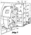
- the present expandable lavatory 10 is shown disposed proximate the exit door 11 of an airplane (not shown).
- the terms outboard, inboard, fore and aft have the same meanings ordinarily attributed to these words in an airplane.
- the dual pivot expandable lavatory 10 comprises a fixed or stationary sidewall lavatory subassembly 12, a primary pivoting module 14, a secondary pivoting module 16, a locking system 18 (not shown in FIGS. 1 or 2, but see FIG. 5 and more particularly FIGS. 12 - 18) and an optional flight attendant's seat 20.
- the lavatory 10 is in the stowed position shown in FIG. 1 when the airplane is on the ground, taxiing, during takeoff, climbout and landing. While on the ground, passengers may be loaded on the airplane or deplaned and operations conducted in a routine manner.
- an attendant After takeoff and climbout, an attendant would unlock the primary module 14 manually using a latch grab handle 22 and deploy both the primary module 14 and the secondary module 16 into the area or space proximate the doorway 11, as shown in FIG. 2. Once extended, the primary module 14 is relocked, using the latch grab handle 22, in the deployed position. While deployed, access to die inside of the lavatory 10 is through a conventional door whereby the lavatory is available for passenger and crew use.
- FIGS. 3 and 4 show cross sectional views of the expandable lavatory 10 in the stowed and deployed positions, respectively.
- a conventional sink cabinet 26 and other components are carried by the primary module 14. These components are completely located within the envelope of the stationary sidewall lavatory subassembly 12 proximate a toilet 28 when the lavatory 10 is in a stowed position.
- FIG. 4 also see FIG. 7
- passengers should not perceive any significant difference between the instant lavatory and a conventional lavatory.
- FIG. 6 there is shown a simplified exploded perspective view of the dual pivot expandable lavatory 10 of the present invention.
- the stationary or fixed subassembly 12 is essentially a box configured to coincide with the interior contour of the airplane.
- the box has a width (fore and aft) which is considerably less than conventional lavatories.
- a conventional lavatory has a width of between thirty three (33) inches to about thirty six (36) inches.
- the present lavatory 10 is about twenty two (22) inches wide when in a stowed position.
- the stationary subassembly 12 is intended to be placed outboard of an aisle of the airplane, but may be suitably positioned anywhere in the airplane. As is obvious the subassembly and thus the lavatory 10 may be repositioned in a direction opposite to that shown.
- the fixed subassembly 12 comprises an outboard wall 30, an open aft side wall 32 which permits the pivoting and stowage of the primary module 14 and the secondary module 16, a solid forward side wall 34, a hollow corner post 36, an aisle "wall” 38, a conventional lavatory door 24, a fixed floor pan 40, a ceiling 42 and a plurality of conventional lavatory mounts 44 and 46.
- the toilet 28 is affixed to the floor pan 40.
- the outboard wall 30 supports an amenities console 45 above the toilet.
- the amenities console may contain seat covers, facial tissues, air sick bags and sanitary napkins (not shown).
- the outboard wall 30, open side wall 32 and the solid side wall 34 are attached to suitable airplane structure, such as in the flooring and ceiling , by the conventional lavatory mounts 44 and 46.
- the corner post 36 Affixed to the open side wall 32 is the corner post 36 to which the primary module 14 is pivotably attached as better shown in and discussed below with respect to FIG. 6A. Also see FIGS. 3 and 4.
- the aisle "wall" 38 comprises a returned edge 48 (see FIGS. 4 and 5) on the forward side wall, a threshold 50 and a header 52.
- the lavatory door 24 is suitably hinged by a conventional means, not shown, to the corner post 36.
- the primary module 14 is pivotably attached to the corner post 46 by means of a pair of hinge subassemblies 48 disposed at the upper and lower portions of the corner post 46.
- the hinge subassembly disposed at the upper portion of the corner post 46 is shown in exploded form detail in FIG. 6A whereas the lower hinge subassembly is shown installed in the corner post 46.
- Each hinge subassembly 48 comprises a fixed mounting plate 54 suitably attached within a recess formed in the post 46, a pivoting mounting plate 56 , thrust bearings 58 and a conventional hinge pin 60.
- the pivoting mounting plate 56 is pivotably attached to the fixed mounting plate by means of the thrust bearings 58 and the hinge pin 60.
- the pivoting mounting plate 56 attaches to the primary pivoting module 14 as shown in a simplified way in FIGS. 4 and 5.
- the open wall has an outline 62 which is configured to accommodate the shapes of both the primary pivoting module 14 and the secondary pivoting module 16 whereby in use both modules may be positioned in a stowed and a deployed position. Except for a slot 64 which cooperates with the locking system 18 to be described later, the edge of the perimeter of the outline 62 is provided with an elastomeric seal 66.
- the seal 66 is provided on both the exterior surface and the interior surface of the edge of the outline 62 and cooperates with complementary surfaces of the primary pivoting module 14 and the secondary pivoting module 16 so that in use no objectionable odors or noise are detectable from the lavatory.
- the seal 66 also permits an occupant of the lavatory 10 to have privacy when the lavatory is in its deployed position.
- the toilet 28 is offset toward the expanding side of the lavatory 10. This offset provides an occupant with sufficient shoulder space when the lavatory 10 is in an expanded or deployed state.
- the undersurface of a toilet shroud 68 which is attached to the outboard wall 30, stops above the lower portion of the secondary pivoting module 16 and the floor pan 40 which is fixed within the stationary subassembly 12.
- the undersurface of the shroud 68 and the floor pan 40 are shaped or contoured to receive the secondary pivotable module 10 when the lavatory 10 is in a stowed position.
- the primary pivoting module 14 comprises a primary moving wall 70 having a shape complementary to the inboard portion of the outline 62 and having a dimension that is slighter greater than that outline portion.
- the primary moving wall 70 is attached to the pivoting mounting plates 56 and is suitably attached to a top panel 72 and a bottom panel 74.
- an upper flange 75 formed on the top panel 72 and a lower flange 77 formed on the bottom panel 74 press against the seal 66 on the interior edge of the outline 62 and assist in forming the conventional looking lavatory 10 shown in FIG. 7.
- the primary pivoting module 14 also comprises a primary shell 76 which is somewhat smaller than the primary moving wall 70 thereby forming a primary moving wall overlap 78.
- the primary shell 76 may be made integral with the top panel and the bottom panel.
- a lip 79 extends along the outboard exterior edge of the shell 76 from the bottom panel 74 to the top panel 72.
- An elastomeric center seal 81 is disposed over the lip 79 and cooperates with the perimeter seal 66 formed over the outline 62 in the open wall 32 to mitigate undesirable odors and noises.
- FIGS 7 and 10 suitably affixed within the primary shell are typical amenities and a plumbing system 83.
- the amenities may include a sink cabinet 80, a trash receptacle 82, mirror 84, light 86, and other typical amenities, such as cups, soap, hand towels, not shown in FIG. 7.
- FIG. 10 illustrates the plumbing system 83 which comprises a conventional supply line 88, supply valve 90 for both the sink cabinet 80 and the toilet 28, toilet drain valve 92, water heater 94, water filter 96, hot and cold valves 96, 98, a system drain valve 101, and a gray water plumbing subsystem 102.
- the gray water plumbing subsystem could either include an optional sump 103 or a separate system drain line 104.
- An alternative configuration 83' for the plumbing system used in connection with the present invention is shown in FIG. 11.
- the primary module 14 cooperates with the secondary pivoting module 16 to form the lavatory 10 of the present invention.
- the secondary module comprises a secondary moving wall 104, a secondary shell 106 having a continuous flange 108 about its interior periphery, guide rollers 110 mounted on the inboard edge of the secondary moving wall 104 (see FIGS. 8 and 9) and a conventional continuous pivotable hinge (not shown).
- the secondary moving wall 104 is pivotably attached by the continuous pivotable hinge to the outboard portion of the outline 62 of the open wall 32 and is sized to slightly overlap the outline when the lavatory 10 is in a stowed position.
- the inboard edge 112 of the secondary moving wall 104 is configured as a recessed flange 108 which sealingly cooperates with and is covered by the primary moving wall overlap in a stowed position. In that stowed position, the secondary module 16 is trapped between the primary moving wall overlap and the open wall 32.
- the primary moving wall and the secondary moving wall present, in the stowed position, a substantially continuous, smooth surface to the airplane passengers.
- the secondary shell 106 of the secondary pivotable module 16 slides under the toilet shroud 68 and above the floor pan 40; see FIG. 9.
- the secondary shell 106 is placed in intimate contact with the perimeter seal 66 formed over the edge of the outline; see FIGS. 7 and 8.
- the secondary shell flanges 108 stop against the perimeter seal 66 on the inside surface of the open wall preventing further outward movement of the secondary module 16.
- the center seal 81 on the primary shell 76 makes contact with the inboard edge of the secondary shell 106 preventing movement of the secondary shell inwardly toward the stationary subassembly 12.
- FIG. 12 shows a portion of the primary pivotable module 14 in a stowed and locked position proximate the open wall 32.
- the locking system 18 comprises a torque tube 112 and similar upper and lower locking system subassemblies 114 disposed at the top and bottom panels 72, 74 of the primary pivoting module 14.
- the torque tube 112 is rotatably supported on the interior surface of the primary movable wall 70.
- a pin 116 provided at the distal ends of the torque tube 112, is offset from its centerline.
- a latch grab handle 118 (shown in solid lines in FIG. 12 and in phantom in FIG. 13) is suitably affixed to the torque tube 112.
- the grab handle 118 is accessible by a flight attendant from the exterior of the primary movable wall 70 and is attached to the torque tube 112 through a recessed escutcheon 120.
- the escutcheon 120 is formed on the outside of the primary movable wall 70. See FIGS. 1 and 2.
- the upper locking subassembly is pivotably attached to the top panel 72 of the primary movable module 14 and comprises a pivotable arcuately-shaped main rocker arm 122.
- the rocker arm 122 comprises a raised rail 124 , a rocker arm bearing 126 , an elongated pit slot 128 disposed proximate the primary moving wall and a hook-shaped recess 130 disposed proximate the deployed position stop.
- the rocker arm bearing is positioned about a pin affixed to the top panel of the primary pivotable module whereby the rocker arm may be pivoted in use. As perhaps best seen in FIGS. 14 and 15, the upper offset pin of the torque tube is inserted into the pin slot on the main rocker arm.
- the upper locking subassembly also comprises a safety stop subassembly.
- the safety stop subassembly comprises a guide arm and a safety stop arm which act together as one unit.
- the guide arm is inserted through slots formed in the raised rail and extends from the pin slot to the hook shaped recess of the arcuate rocker arm.
- the guide arm is pivotably attached to the rocker arm by means of a pin located within the raised rail at a position intermediate its distal ends.
- the raised rail on the main rocker arm moves through the slot in the outline edge of the open wall.
- One of the edges of the slot forces the guide arm against a guide arm spring to align with the raised rail thus positioning the safety stop arm against an offset stop affixed to the upper portion of the torque tube below the offset pin.
- the safety stop subassembly prevents the torque tube from turning and thus locks the main rocker arm in line with the slot formed in the sealed edge of the open wall.
- the purpose of the safety stop subassembly is to prevent inadvertent closing of the grab handle which would cause a jambing condition.
- die present locking system is quite simple. It is analogous to a stick placed in the track of a sliding window to block it in either a closed or open position. Once the stick is removed, the window can be moved.
- the main rocker arm functions as the stick and the deployed position stop on the top panel and the stowed position stop formed on the primary moving wall each functions, by analogy, as the window frame.
- the grab handle 118 lays flat in the escutcheon 120 whereby when a flight attendant pulls the grab handle outward, the torque tube turns accordingly (counter clockwise).
- the offset pins pivot the rocker arm away from a position where the rocker arm is lodged against an edge of the slot formed in the open wall whereby the raised rail may be aligned with the slot formed in the sealed edge of the open wall.
- the primary pivoting module is then free to pivot between the deployed position stop on the top panel and the stowed position stop formed on the primary moving wall.
- a single flight attendant seat may optionally be affixed to the exterior of the primary moving wall of the primary pivotable module. See FIGS. 1 and 2. If used, the attendant's seat must always face aft and requires a support foot assembly which transfer loads downwardly to the floor structure.
- the support foot assembly is disposed on the lower exterior of the primary moving wall proximate the airplane flooring.
- the optional support foot assembly is not shown in FIGS. 1 or 2, but is in FIGS. 3 and 4.
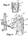
- the support foot assembly is best illustrated in FIGS. 16-19 as comprising a support foot housing, a lockable foot slidably positioned within the housing, a bottom leg pivotably pinned to the slidable foot as by a bottom pin, a top leg pivotably pinned by means of a center pin to the bottom leg and securely affixed to a top leg shaft supported by the support foot housing.
- the support foot assembly also comprises a support foot control arm securely affixed to the top leg shaft.
- the control arm is pinned to a swivel end link pinned to a control arm affixed to the main rocker torque tube.
- the support foot In use, the support foot is moved off the floor only when the locking system is disengaged allowing the primary module to pivot. More particularly, in use, the support foot assembly is contolled by the link connected to the main rocker torque tube.
- the control arm pushes the link outboard as shown in FIG. 16 which pushes the foot support control arm towards the right in that figure.
- the control arm thus pivots in a counterclockwise direction thereby rotating the top leg in a upward direction as viewed in FIG. 16.
- the upper leg rotates upwardly, it pulls the bottom leg upwardly through the center pin which causes the support foot to slide upwardly within the support foot housing as is best seen in FIG. 18.
- the process is reversed as is perhaps best seen in FIGS. 17 and 19. In the engaged position, the top and bottom legs are positioned past the center of their pivot points and stop against the inside of the support foot.
- the grab handle is pulled to the substantially perpendicular out position shown in in FIGS. 12, 13 (in phantom) and 14. This is a clear visual indication that the locking system is disengaged.
- the primary module may then be pulled out of the stationary assembly by the attendant.
- the pivoting motion of the primary module pushes the secondary module outward as the secondary module rolls over the primary shell by means of rollers disposed on the inboard edge of the secondary moving wall (see FIGS. 3 and 4, but especially FIGS. 8 and 9). Both modules continue outward until the secondary module stops in place when the perimeter flange is pulled against the sealed edge of the open wall; see FIG. 21.
- the primary module continues to move outwardly to the fully deployed position shown in FIG. 22 wherein the lock stops are positioned against the perimeter seals and the center seal is positioned against the secondary shell.
- the flight attendant returns the grab handle to a position within the escutcheon and the lock is re-engaged.
- the expandable lavatory is now ready for use. Stowing of the lavatory is a reverse of the above wherein the locking assembly is disengaged, the unit is pushed closed by the attendant and the locking assembly is re-engaged.
Abstract
Description
Claims (4)
- An expandable lavatory comprising:(a) a stationary assembly having a substantially open side wall and a corner post attached to said side wall;(b) a toilet assembly affixed within said stationary assembly;(c) a primary module pivotably attached to said corner post, said primary module being movable within said side wall from a stowed position substantially within said stationary assembly to a deployed position substantially outside of said stationary assembly;(d) locking means for securing said primary module within said lavatory in said stowed position and in said deployed position, and(e) a secondary module pivotably attached to said side wall and being movable within said side wall from a stowed position substantially within said stationary assembly to a deployed position substantially outside of said stationary assembly, said secondary module being provided with means for urging movement of said secondary module when said primary module is moved.
- An expandable lavatory disposed in an airplane, said airplane having a passenger doorway area, said lavatory comprising:(a) a stationary assembly disposed proximate said passenger doorway area, said stationary assembly comprising a side wall, a corner post affixed to said side wall and a lavatory door pivotably attached to said corner post;(b) a toilet assembly affixed within said stationary assembly away from said lavatory door;(c) a primary module pivotably attached to said post, said primary module being movable within an opening formed in said side wall from a stowed position substantially within said stationary assembly to a deployed position substantially outside of said stationary assembly within said doorway areas;(d) locking means for security said primary module within said lavatory in said stowed position and in said deployed position, and(e) a secondary module pivotably attached to said side wall and being movable within said opening from a stowed position substantially within said stationary assembly to a deployed position substantially outside of said stationary assembly within said doorway area, said secondary module being provided with means for urging movement of said secondary module when said primary module is moved.
- A process for using unused doorway space proximate a doorway disposed in an airplane, said process comprising:(a) disposing a stationary assembly proximate said passenger doorway area, said stationary assembly comprising a side wall having an opening, a corner post affixed to said side wall and a lavatory door pivotably attached to said corner hinge subassembly;(b) affixing a toilet assembly within said stationary assembly away from said lavatory door;(c) pivotably attaching a primary module to said corner post;(d) pivotably attaching a secondary module to said side wall;(e) providing said secondary module with means for urging movement of said secondary module when said primary module is pivoted(e) locking said primary module and said secondary module within said lavatory in a stowed position substantially within said stationary assembly;(f) unlocking said primary module and said secondary module when said airplane is in normal flight,(g) moving each of said modules within said opening from said stowed position to a deployed position substantially outside of said stationary assembly within said doorway area.
- A process for increasing the revenue generating capacity of an airplane, said airplane having a doorway area and a plurality of passenger seats, said process comprising:(a) positioning an expandable lavatory which is narrower than a conventional lavatory proximate said doorway area whereby space within said airplane may be saved;(b) providing said lavatory with a pivotable primary module and a pivotable secondary module which may be deployed within said doorway area, and(c) increasing the number of passenger seats within said airplane.
Applications Claiming Priority (2)
| Application Number | Priority Date | Filing Date | Title |
|---|---|---|---|
| US08/822,030 US6079669A (en) | 1997-03-24 | 1997-03-24 | Dual pivot expandable lavatory |
| US822030 | 1997-03-24 |
Publications (3)
| Publication Number | Publication Date |
|---|---|
| EP0867365A2 true EP0867365A2 (en) | 1998-09-30 |
| EP0867365A3 EP0867365A3 (en) | 1998-11-18 |
| EP0867365B1 EP0867365B1 (en) | 2003-08-20 |
Family
ID=25234926
Family Applications (1)
| Application Number | Title | Priority Date | Filing Date |
|---|---|---|---|
| EP98200909A Expired - Lifetime EP0867365B1 (en) | 1997-03-24 | 1998-03-23 | Dual pivot expandable lavatory |
Country Status (4)
| Country | Link |
|---|---|
| US (1) | US6079669A (en) |
| EP (1) | EP0867365B1 (en) |
| CA (1) | CA2232928C (en) |
| DE (1) | DE69817241T2 (en) |
Cited By (31)
| Publication number | Priority date | Publication date | Assignee | Title |
|---|---|---|---|---|
| EP1209078A3 (en) * | 2000-11-22 | 2003-10-22 | Jamco Corporation | Expandable lavatory unit for aircraft |
| WO2005110843A2 (en) * | 2003-10-17 | 2005-11-24 | The Boeing Company | Architectural archway for an aircraft |
| DE102005035752A1 (en) * | 2005-07-29 | 2007-02-08 | Airbus Deutschland Gmbh | Passenger-compartment for use in cabin area of commercial aircraft, has wall segments spaced apart from each other in longitudinal direction of cabin area such that opening for access door is formed between segments at compartment |
| EP1883579A2 (en) * | 2005-05-25 | 2008-02-06 | Air New Zealand Limited | Improved facility structures for commercial passenger aircraft |
| US7380752B2 (en) | 2003-10-17 | 2008-06-03 | The Boeing Company | Aircraft interior architecture |
| US7455263B2 (en) | 2005-04-22 | 2008-11-25 | The Boeing Company | Airplane interior systems |
| US7717371B2 (en) | 2006-01-25 | 2010-05-18 | Airbus Deutschland Gmbh | Resting deck in an aircraft with resting cabins |
| US7721990B2 (en) | 2005-07-29 | 2010-05-25 | Airbus Deutschland Gmbh | Passenger compartment |
| WO2011009912A1 (en) * | 2009-07-23 | 2011-01-27 | Airbus Operations Gmbh | Monument for a cabin of a vehicle |
| WO2011101385A3 (en) * | 2010-02-19 | 2011-10-27 | Airbus Operations Gmbh | Toilet assembly for a means of transportation |
| WO2012119718A1 (en) * | 2011-03-04 | 2012-09-13 | Airbus Operations Gmbh | Aircraft cabin section |
| WO2013045945A2 (en) | 2011-09-29 | 2013-04-04 | Escape Enviro Limited | Exercise weight structure |
| WO2013123080A1 (en) | 2012-02-14 | 2013-08-22 | C&D Zodiac, Inc. | Lavatory with recessed flight attendant seat |
| WO2013139780A1 (en) * | 2012-03-23 | 2013-09-26 | Airbus Operations Gmbh | Adaptor for mounting a seat in a cabin of a vehicle, seat for a cabin of a vehicle and vehicle with a cabin and a seat |
| WO2014031915A1 (en) * | 2012-08-23 | 2014-02-27 | Mag Aerospace Industries, Inc. | Improved storage solutions using aircraft lavatories |
| WO2014130590A1 (en) | 2013-02-19 | 2014-08-28 | C&D Zodiac, Inc. | Modular lavatory with alcove |
| CN104136320A (en) * | 2012-02-24 | 2014-11-05 | 空中客车德国运营有限责任公司 | Toilet module for a vehicle and a vehicle comprising a vehicle cabin and at least one toilet module |
| EP2803578A1 (en) * | 2013-05-15 | 2014-11-19 | Airbus Operations GmbH | Expandable aircraft monument |
| EP2803577A1 (en) * | 2013-05-15 | 2014-11-19 | Airbus Operations GmbH | Modifiable aircraft monument |
| EP2837562A1 (en) * | 2013-08-16 | 2015-02-18 | Airbus Operations GmbH | On-board-wheelchair stowage |
| CN104822592A (en) * | 2012-11-05 | 2015-08-05 | C&D佐迪阿克公司 | Wheel chair accessible lavatory |
| WO2015124794A1 (en) * | 2014-02-24 | 2015-08-27 | Airbus Operations Gmbh | Module for an aircraft cabin with a seat fastened to a door |
| WO2015155065A1 (en) * | 2014-04-07 | 2015-10-15 | Airbus Operations Gmbh | Retaining system for a movable component |
| CN104995089A (en) * | 2013-02-11 | 2015-10-21 | Be航天公司 | Compact aircraft gallery and lavatory arrangement and articulating lavatory partition for an aircraft |
| US9260189B2 (en) | 2012-02-14 | 2016-02-16 | C&D Zodiac, Inc. | Modular lavatory with alcove |
| US9511867B2 (en) | 2013-09-23 | 2016-12-06 | Airbus Operations Gmbh | Device for mounting a vehicle attendant seat in a cabin of a vehicle, cabin arrangement in a vehicle, and vehicle with at least one cabin arrangement |
| US9896212B2 (en) | 2012-02-14 | 2018-02-20 | C&D Zodiac, Inc. | Integrated centerline lavatory galley monument |
| EP2675710B1 (en) | 2011-02-18 | 2018-04-04 | Airbus Operations GmbH | Modular cabin segment, cabin for a vehicle and vehicle with a cabin |
| EP3354568A1 (en) * | 2017-01-26 | 2018-08-01 | Airbus Operations GmbH | Forward interior space arrangement for an aircraft |
| EP3922554A1 (en) * | 2020-06-12 | 2021-12-15 | The Boeing Company | Monument having attachment system with corner bracket fitting |
| USD944079S1 (en) | 2020-06-12 | 2022-02-22 | The Boeing Company | Corner bracket fitting for use in an attachment system |
Families Citing this family (54)
| Publication number | Priority date | Publication date | Assignee | Title |
|---|---|---|---|---|
| US6443393B1 (en) * | 2001-02-12 | 2002-09-03 | Able Corporation | Air heater or dryer apparatus, for use on aircraft |
| US6604709B1 (en) | 2002-02-20 | 2003-08-12 | The Boeing Company | Dot (department of transportation) lavatory and shower combination |
| US20030177572A1 (en) * | 2002-03-22 | 2003-09-25 | Jeanne Guerin | Aircraft passenger cleansing system |
| FR2842498B1 (en) * | 2002-07-19 | 2005-05-13 | Airbus | AIRCRAFT CABIN MODULE |
| US6859950B2 (en) * | 2003-04-29 | 2005-03-01 | The Boeing Company | Apparatus and methods for drain strainer assembly installation and maintenance |
| US7117646B2 (en) * | 2003-07-18 | 2006-10-10 | Triumph Boats, Inc. | Privacy enclosure |
| DE10339077A1 (en) * | 2003-08-26 | 2005-03-31 | Airbus Deutschland Gmbh | Passenger compartment in the cabin of a commercial airplane |
| US6889936B1 (en) | 2003-11-17 | 2005-05-10 | The Boeing Company | Apparatus and methods for increasing useable space within aircraft lavatories |
| US7168108B2 (en) * | 2004-03-23 | 2007-01-30 | The Boeing Company | Shower system |
| US7100872B2 (en) * | 2004-04-15 | 2006-09-05 | The Boeing Company | Lavatory fast pack system and method |
| US20060064815A1 (en) * | 2004-09-24 | 2006-03-30 | The Boeing Company | Mist Delivery System |
| US7237749B2 (en) | 2004-12-14 | 2007-07-03 | The Boeing Company | Collapsible mobile platform interior structure |
| DE102006016755B3 (en) * | 2006-04-10 | 2007-11-29 | Airbus Deutschland Gmbh | Fuselage section for aircraft, has fuselage skeleton that is fixed to outer skin construction at door opening, so that ribs in fuselage skeleton divides door opening into multiple opening |
| US7866603B2 (en) * | 2007-04-27 | 2011-01-11 | The Boeing Company | Methods and apparatus for an aircraft lavoratory |
| DE102008053228A1 (en) * | 2008-10-27 | 2010-04-29 | Lufthansa Technik Ag | Modular shower cabin for aircraft |
| JP5532895B2 (en) * | 2009-12-15 | 2014-06-25 | 横浜ゴム株式会社 | Aircraft restroom unit |
| US8590838B2 (en) * | 2010-04-20 | 2013-11-26 | Be Intellectual Property, Inc. | Aircraft interior lavatory |
| JP5728843B2 (en) * | 2010-07-28 | 2015-06-03 | 横浜ゴム株式会社 | Aircraft restroom unit |
| USD749709S1 (en) | 2011-04-18 | 2016-02-16 | B/E Aerospace, Inc. | Aircraft interior lavatory |
| US20130099055A1 (en) * | 2011-10-24 | 2013-04-25 | Schneller, Inc. | Integrated lavatory pan for commercial aircraft |
| DE102012005712A1 (en) * | 2011-10-29 | 2013-05-02 | Diehl Aircabin Gmbh | Changing room in an airplane and method for converting an aircraft with a changing room |
| US20130206907A1 (en) * | 2012-02-14 | 2013-08-15 | C&D Zodiac, Inc. | Expandable lavatory with movable wall |
| JP6102910B2 (en) * | 2012-02-23 | 2017-03-29 | 横浜ゴム株式会社 | Installation method of aircraft restroom unit and aircraft |
| JP5825192B2 (en) * | 2012-05-11 | 2015-12-02 | 横浜ゴム株式会社 | Aircraft restroom unit and arrangement structure thereof |
| JP5849855B2 (en) * | 2012-05-11 | 2016-02-03 | 横浜ゴム株式会社 | Aircraft restroom unit and arrangement structure thereof |
| EP2664542A1 (en) * | 2012-05-18 | 2013-11-20 | Airbus Operations GmbH | Vehicle lavatory |
| JP6276263B2 (en) * | 2012-07-17 | 2018-02-07 | ビーイー・エアロスペース・インコーポレーテッドB/E Aerospace, Inc. | Space efficient bathroom module for commercial aircraft |
| US9308997B2 (en) * | 2012-09-17 | 2016-04-12 | The Boeing Company | Lavatory reconfiguration system |
| US8720827B2 (en) * | 2012-09-25 | 2014-05-13 | The Boeing Company | Dual function lavatory door |
| US9302772B2 (en) * | 2012-10-05 | 2016-04-05 | The Boeing Company | Aircraft lavatory and galley separated by an internal wall having an intermediate notch that improves the lavatory environment |
| JP2014076713A (en) * | 2012-10-10 | 2014-05-01 | Yokohama Rubber Co Ltd:The | Aircraft toilet unit |
| US8752339B1 (en) | 2012-11-01 | 2014-06-17 | The Boeing Company | Convertible door system and method of operation |
| EP2991899B1 (en) * | 2013-04-29 | 2018-06-06 | C&D Zodiac, Inc. | Compact cabin attendant seat stowage |
| DE102013008288A1 (en) * | 2013-05-15 | 2014-11-20 | Airbus Operations Gmbh | aircraft area |
| DE102013008290A1 (en) * | 2013-05-15 | 2014-11-20 | Airbus Operations Gmbh | Multifunctional aircraft monument and aircraft area |
| US9321533B2 (en) * | 2013-05-29 | 2016-04-26 | The Boeing Company | Aircraft passageway storage units |
| US8944377B2 (en) | 2013-06-11 | 2015-02-03 | The Boeing Company | Lavatory reconfiguration system |
| US9688407B2 (en) | 2013-10-03 | 2017-06-27 | The Boeing Company | Modular lavatory system |
| US10464677B2 (en) * | 2014-04-07 | 2019-11-05 | B/E Aerospace, Inc. | Aircraft modular lavatory system |
| US9862491B2 (en) * | 2014-04-07 | 2018-01-09 | B/E Aerospace, Inc. | Modular lavatory system optimized for narrow body commercial aircraft |
| WO2016162918A1 (en) * | 2015-04-06 | 2016-10-13 | 株式会社ジャムコ | Aeroplane lavatory unit |
| DE102015211813A1 (en) * | 2015-06-25 | 2016-12-29 | Airbus Operations Gmbh | Sanitary module with folding niche for an airplane and aircraft door area |
| US9840332B2 (en) * | 2015-10-15 | 2017-12-12 | The Boeing Company | Deployable door-mounted seat |
| DE102016207607A1 (en) * | 2016-05-03 | 2017-11-09 | Airbus Operations Gmbh | Expandable aircraft monument and aircraft area with an expandable aircraft monument |
| DE102016221111A1 (en) * | 2016-10-26 | 2018-04-26 | Airbus Operations Gmbh | Cabin monument for an aircraft |
| USD914568S1 (en) * | 2017-10-30 | 2021-03-30 | Textron Innovation Inc. | Divergent entryway |
| US11919643B2 (en) * | 2018-04-10 | 2024-03-05 | Rockwell Collins, Inc. | Self-deploying counter for multimode transformable monuments |
| US11130305B2 (en) | 2018-08-21 | 2021-09-28 | The Boeing Company | Trash compactor assembly |
| US11472555B2 (en) * | 2018-10-26 | 2022-10-18 | The Boeing Company | Aft wall for a lavatory monument of an aircraft |
| US11434023B2 (en) * | 2019-07-18 | 2022-09-06 | The Boeing Company | Presence detection systems and methods with increased occupancy status determination |
| SG10201908047PA (en) * | 2019-08-30 | 2021-03-30 | St Eng Aerospace Ltd | Accessible Aircraft Lavatory |
| DE102020104544A1 (en) | 2020-02-20 | 2021-08-26 | Airbus Operations Gmbh | Module for forming a monument for an aircraft |
| US20220177136A1 (en) * | 2020-12-07 | 2022-06-09 | The Boeing Company | Convertible Aircraft Cabin Monument |
| BR102022003422B1 (en) * | 2022-02-23 | 2022-09-27 | João Batista Rosa | RETRACTABLE COMPARTMENT FOR SHOWER AND TOILET |
Citations (5)
| Publication number | Priority date | Publication date | Assignee | Title |
|---|---|---|---|---|
| US3898704A (en) | 1974-07-18 | 1975-08-12 | Mc Donnell Douglas Corp | Convertible seat-bed equipment |
| US4589463A (en) | 1984-09-28 | 1986-05-20 | Falcon Jet Corporation | Expandable volume lavatory |
| US4646145A (en) | 1980-04-07 | 1987-02-24 | R. D. Percy & Company | Television viewer reaction determining systems |
| US4884767A (en) | 1988-04-04 | 1989-12-05 | Jamco Corporation | Lavatory module for a passenger airplane |
| US5150863A (en) | 1990-08-22 | 1992-09-29 | Jamco Corporation | Lavatory unit for a passenger airplane |
Family Cites Families (12)
| Publication number | Priority date | Publication date | Assignee | Title |
|---|---|---|---|---|
| US1850747A (en) * | 1930-07-25 | 1932-03-22 | Flagg Ernest | Compartment vehicle |
| US2188562A (en) * | 1938-10-28 | 1940-01-30 | Andersen Leif | Actuating mechanism for a plumbing fixture |
| US2443214A (en) * | 1945-06-29 | 1948-06-15 | Emory C Williams | Toilet |
| US2681016A (en) * | 1951-10-15 | 1954-06-15 | Pullman Standard Car Mfg Co | Vehicle room arrangement |
| US2760443A (en) * | 1953-06-04 | 1956-08-28 | Budd Co | Private room accommodation for vehicles |
| US2914001A (en) * | 1955-10-13 | 1959-11-24 | Budd Co | High capacity private compartment passenger vehicle |
| US4100857A (en) * | 1977-04-11 | 1978-07-18 | Pullman Incorporated | Passageway between adjacent railway passenger car compartments |
| US4645145A (en) * | 1984-09-28 | 1987-02-24 | Falcon Jet Corporation | Combination toilet and vanity |
| US4681044A (en) * | 1985-12-27 | 1987-07-21 | Dallman Ernest R | Access door system |
| US5083727A (en) * | 1990-01-02 | 1992-01-28 | The Boeing Company | Aircraft cabin system for selectivley locating interior units |
| DE4300877A1 (en) * | 1993-01-15 | 1994-07-21 | Deutsche Aerospace Airbus | plane |
| AUPM872994A0 (en) * | 1994-10-11 | 1994-11-03 | Windus, Donald Arthur | Shower cubicle |
-
1997
- 1997-03-24 US US08/822,030 patent/US6079669A/en not_active Expired - Fee Related
-
1998
- 1998-03-23 DE DE69817241T patent/DE69817241T2/en not_active Expired - Lifetime
- 1998-03-23 EP EP98200909A patent/EP0867365B1/en not_active Expired - Lifetime
- 1998-03-24 CA CA002232928A patent/CA2232928C/en not_active Expired - Lifetime
Patent Citations (5)
| Publication number | Priority date | Publication date | Assignee | Title |
|---|---|---|---|---|
| US3898704A (en) | 1974-07-18 | 1975-08-12 | Mc Donnell Douglas Corp | Convertible seat-bed equipment |
| US4646145A (en) | 1980-04-07 | 1987-02-24 | R. D. Percy & Company | Television viewer reaction determining systems |
| US4589463A (en) | 1984-09-28 | 1986-05-20 | Falcon Jet Corporation | Expandable volume lavatory |
| US4884767A (en) | 1988-04-04 | 1989-12-05 | Jamco Corporation | Lavatory module for a passenger airplane |
| US5150863A (en) | 1990-08-22 | 1992-09-29 | Jamco Corporation | Lavatory unit for a passenger airplane |
Cited By (82)
| Publication number | Priority date | Publication date | Assignee | Title |
|---|---|---|---|---|
| EP1209078A3 (en) * | 2000-11-22 | 2003-10-22 | Jamco Corporation | Expandable lavatory unit for aircraft |
| US7469860B2 (en) | 2003-10-17 | 2008-12-30 | The Boeing Company | Aircraft archway architecture |
| WO2005110843A2 (en) * | 2003-10-17 | 2005-11-24 | The Boeing Company | Architectural archway for an aircraft |
| WO2005110843A3 (en) * | 2003-10-17 | 2006-01-12 | Boeing Co | Architectural archway for an aircraft |
| US7252267B2 (en) | 2003-10-17 | 2007-08-07 | The Boeing Company | Aircraft archway architecture |
| US7293739B2 (en) | 2003-10-17 | 2007-11-13 | The Boeing Company | Aircraft archway |
| US7516919B2 (en) | 2003-10-17 | 2009-04-14 | The Boeing Company | Aircraft archway architecture |
| US7331545B2 (en) | 2003-10-17 | 2008-02-19 | The Boeing Company | Aircraft archway |
| US7380752B2 (en) | 2003-10-17 | 2008-06-03 | The Boeing Company | Aircraft interior architecture |
| US7448574B2 (en) | 2003-10-17 | 2008-11-11 | The Boeing Company | Aircraft archway architecture |
| US7455263B2 (en) | 2005-04-22 | 2008-11-25 | The Boeing Company | Airplane interior systems |
| EP1883579A2 (en) * | 2005-05-25 | 2008-02-06 | Air New Zealand Limited | Improved facility structures for commercial passenger aircraft |
| EP1883579A4 (en) * | 2005-05-25 | 2012-08-01 | Air New Zealand Ltd | Improved facility structures for commercial passenger aircraft |
| DE102005035752B4 (en) * | 2005-07-29 | 2013-02-28 | Airbus Operations Gmbh | passenger compartment |
| US7721990B2 (en) | 2005-07-29 | 2010-05-25 | Airbus Deutschland Gmbh | Passenger compartment |
| DE102005035752A1 (en) * | 2005-07-29 | 2007-02-08 | Airbus Deutschland Gmbh | Passenger-compartment for use in cabin area of commercial aircraft, has wall segments spaced apart from each other in longitudinal direction of cabin area such that opening for access door is formed between segments at compartment |
| US7717371B2 (en) | 2006-01-25 | 2010-05-18 | Airbus Deutschland Gmbh | Resting deck in an aircraft with resting cabins |
| WO2011009912A1 (en) * | 2009-07-23 | 2011-01-27 | Airbus Operations Gmbh | Monument for a cabin of a vehicle |
| EP2735509A1 (en) * | 2009-07-23 | 2014-05-28 | Airbus Operations GmbH | Monument for an aircraft cabin |
| US8662444B2 (en) | 2009-07-23 | 2014-03-04 | Airbus Operations Gmbh | Monument for a cabin of a vehicle |
| US8672267B2 (en) | 2010-02-19 | 2014-03-18 | Airbus Operations Gmbh | Toilet arrangement for a vehicle |
| CN102762455B (en) * | 2010-02-19 | 2016-05-18 | 空中客车德国运营有限责任公司 | For the washroom device of the vehicles |
| WO2011101385A3 (en) * | 2010-02-19 | 2011-10-27 | Airbus Operations Gmbh | Toilet assembly for a means of transportation |
| EP3957565A1 (en) * | 2010-02-19 | 2022-02-23 | Airbus Operations GmbH | Toilet arrangement for a means of transport |
| EP3936432A1 (en) * | 2010-02-19 | 2022-01-12 | Airbus Operations GmbH | Modular cabin segment, cabin for a vehicle and vehicle with a cabin |
| CN102762455A (en) * | 2010-02-19 | 2012-10-31 | 空中客车德国运营有限责任公司 | Toilet assembly for a means of transportation |
| US9656751B2 (en) | 2010-02-19 | 2017-05-23 | Airbus Operations Gmbh | Modular cabin segment, cabin for a vehicle and vehicle with a cabin |
| US9376211B2 (en) | 2010-02-19 | 2016-06-28 | Airbus Operations Gmbh | Modular cabin segment, cabin for a vehicle and vehicle with a cabin |
| EP3333077A1 (en) * | 2011-02-18 | 2018-06-13 | Airbus Operations GmbH | Modular cabin segment, cabin for a vehicle and vehicle with a cabin |
| EP2675710B1 (en) | 2011-02-18 | 2018-04-04 | Airbus Operations GmbH | Modular cabin segment, cabin for a vehicle and vehicle with a cabin |
| EP3333077B1 (en) | 2011-02-18 | 2021-09-29 | Airbus Operations GmbH | Modular cabin segment, cabin for a vehicle and vehicle with a cabin |
| CN103459251A (en) * | 2011-03-04 | 2013-12-18 | 空中客车作业有限公司 | Aircraft cabin section |
| CN103459251B (en) * | 2011-03-04 | 2016-04-20 | 空中客车作业有限公司 | Aircraft cabin section and aircraft thereof |
| WO2012119718A1 (en) * | 2011-03-04 | 2012-09-13 | Airbus Operations Gmbh | Aircraft cabin section |
| US9327833B2 (en) | 2011-03-04 | 2016-05-03 | Airbus Operations Gmbh | Aircraft cabin ingress and egress door area |
| WO2013045945A2 (en) | 2011-09-29 | 2013-04-04 | Escape Enviro Limited | Exercise weight structure |
| WO2013123080A1 (en) | 2012-02-14 | 2013-08-22 | C&D Zodiac, Inc. | Lavatory with recessed flight attendant seat |
| US9896212B2 (en) | 2012-02-14 | 2018-02-20 | C&D Zodiac, Inc. | Integrated centerline lavatory galley monument |
| US9981747B2 (en) | 2012-02-14 | 2018-05-29 | C&D Zodiac, Inc. | Lavatory with recessed flight attendant seat |
| US10023314B2 (en) | 2012-02-14 | 2018-07-17 | C&D Zodiac, Inc. | Quad modular lavatory with alcoves |
| EP2814736A4 (en) * | 2012-02-14 | 2015-10-14 | C & D Zodiac Inc | Lavatory with recessed flight attendant seat |
| US9527591B2 (en) | 2012-02-14 | 2016-12-27 | C&D Zodiac, Inc. | Modular lavatory with alcove |
| US10093421B2 (en) | 2012-02-14 | 2018-10-09 | C&D Zodiac, Inc. | Dual modular lavatory with alcoves |
| US10301025B2 (en) | 2012-02-14 | 2019-05-28 | C&D Zodiac, Inc. | Business class modular lavatory with alcove |
| US9260189B2 (en) | 2012-02-14 | 2016-02-16 | C&D Zodiac, Inc. | Modular lavatory with alcove |
| US10358219B2 (en) | 2012-02-14 | 2019-07-23 | C&D Zodiac, Inc. | Modular lavatory with sink alcove |
| US9862490B2 (en) | 2012-02-24 | 2018-01-09 | Airbus Operations Gmbh | Toilet module for a vehicle and a vehicle comprising a vehicle cabin and at least one toilet module |
| CN104136320B (en) * | 2012-02-24 | 2017-03-08 | 空中客车德国运营有限责任公司 | Toilette modules for the vehicles and the vehicles including compartment and at least one toilette modules |
| US10899452B2 (en) | 2012-02-24 | 2021-01-26 | Airbus Operations Gmbh | Toilet module for a vehicle and a vehicle including a toilet module |
| CN104136320A (en) * | 2012-02-24 | 2014-11-05 | 空中客车德国运营有限责任公司 | Toilet module for a vehicle and a vehicle comprising a vehicle cabin and at least one toilet module |
| US9802706B2 (en) | 2012-03-23 | 2017-10-31 | Airbus Operations Gmbh | Adaptor for mounting a seat in a cabin of a vehicle, seat for a cabin of a vehicle and vehicle with a cabin and a seat |
| WO2013139780A1 (en) * | 2012-03-23 | 2013-09-26 | Airbus Operations Gmbh | Adaptor for mounting a seat in a cabin of a vehicle, seat for a cabin of a vehicle and vehicle with a cabin and a seat |
| CN104245505A (en) * | 2012-03-23 | 2014-12-24 | 空中客车德国运营有限责任公司 | Adaptor for mounting seat in cabin of vehicle, seat for cabin of vehicle and vehicle with cabin and seat |
| CN104245505B (en) * | 2012-03-23 | 2017-10-24 | 空中客车德国运营有限责任公司 | For seat is arranged in the cabin of the vehicles adaptor, for the vehicles cabin seat and the vehicles with cabin and seat |
| WO2014031915A1 (en) * | 2012-08-23 | 2014-02-27 | Mag Aerospace Industries, Inc. | Improved storage solutions using aircraft lavatories |
| US8991947B2 (en) | 2012-08-23 | 2015-03-31 | Mag Aerospace Industries, Llc | Storage solutions using aircraft lavatories |
| CN104822592A (en) * | 2012-11-05 | 2015-08-05 | C&D佐迪阿克公司 | Wheel chair accessible lavatory |
| CN104995089A (en) * | 2013-02-11 | 2015-10-21 | Be航天公司 | Compact aircraft gallery and lavatory arrangement and articulating lavatory partition for an aircraft |
| CN104995089B (en) * | 2013-02-11 | 2018-01-02 | Be 航天公司 | Compact board galley and toilet arrangement and radial type health division wall for aircraft |
| EP2958801A4 (en) * | 2013-02-19 | 2017-03-22 | C&D Zodiac, Inc. | Modular lavatory with alcove |
| CN105073579A (en) * | 2013-02-19 | 2015-11-18 | C&D佐迪阿克公司 | Modular lavatory with alcove |
| WO2014130590A1 (en) | 2013-02-19 | 2014-08-28 | C&D Zodiac, Inc. | Modular lavatory with alcove |
| EP2803578A1 (en) * | 2013-05-15 | 2014-11-19 | Airbus Operations GmbH | Expandable aircraft monument |
| DE102013008291A1 (en) * | 2013-05-15 | 2014-11-20 | Airbus Operations Gmbh | Expandable aircraft monument |
| US9428274B2 (en) | 2013-05-15 | 2016-08-30 | Airbus Operations Gmbh | Expandable aircraft monument |
| EP2803577A1 (en) * | 2013-05-15 | 2014-11-19 | Airbus Operations GmbH | Modifiable aircraft monument |
| CN104369866A (en) * | 2013-08-16 | 2015-02-25 | 空中客车德国运营有限责任公司 | Storing an on-board-wheelchair on-board an aircraft |
| EP2837562A1 (en) * | 2013-08-16 | 2015-02-18 | Airbus Operations GmbH | On-board-wheelchair stowage |
| US9511867B2 (en) | 2013-09-23 | 2016-12-06 | Airbus Operations Gmbh | Device for mounting a vehicle attendant seat in a cabin of a vehicle, cabin arrangement in a vehicle, and vehicle with at least one cabin arrangement |
| CN106029496B (en) * | 2014-02-24 | 2018-09-07 | 空中客车德国运营有限责任公司 | The module for aircraft cabin with the seat for being fastened to door |
| WO2015124794A1 (en) * | 2014-02-24 | 2015-08-27 | Airbus Operations Gmbh | Module for an aircraft cabin with a seat fastened to a door |
| US10189571B2 (en) | 2014-02-24 | 2019-01-29 | Airbus Operations Gmbh | Module for an aircraft cabin with a seat fastened to a door |
| CN106029496A (en) * | 2014-02-24 | 2016-10-12 | 空中客车德国运营有限责任公司 | Module for an aircraft cabin with a seat fastened to a door |
| RU2686372C2 (en) * | 2014-04-07 | 2019-04-25 | Аирбас Оперейшенс Гмбх | Rolling member fixation system |
| CN106163918B (en) * | 2014-04-07 | 2019-07-09 | 空中客车德国运营有限责任公司 | Holding system for movable member |
| WO2015155065A1 (en) * | 2014-04-07 | 2015-10-15 | Airbus Operations Gmbh | Retaining system for a movable component |
| US10633074B2 (en) | 2014-04-07 | 2020-04-28 | Airbus Operations Gmbh | Retaining system for a movable component |
| CN106163918A (en) * | 2014-04-07 | 2016-11-23 | 空中客车德国运营有限责任公司 | Holding system for movable member |
| EP3354568A1 (en) * | 2017-01-26 | 2018-08-01 | Airbus Operations GmbH | Forward interior space arrangement for an aircraft |
| EP3922554A1 (en) * | 2020-06-12 | 2021-12-15 | The Boeing Company | Monument having attachment system with corner bracket fitting |
| USD944079S1 (en) | 2020-06-12 | 2022-02-22 | The Boeing Company | Corner bracket fitting for use in an attachment system |
| US11702205B2 (en) | 2020-06-12 | 2023-07-18 | The Boeing Company | Monument having attachment system with corner bracket fitting |
Also Published As
| Publication number | Publication date |
|---|---|
| CA2232928C (en) | 2006-05-30 |
| CA2232928A1 (en) | 1998-09-24 |
| EP0867365B1 (en) | 2003-08-20 |
| DE69817241D1 (en) | 2003-09-25 |
| US6079669A (en) | 2000-06-27 |
| DE69817241T2 (en) | 2004-03-11 |
| EP0867365A3 (en) | 1998-11-18 |
Similar Documents
| Publication | Publication Date | Title |
|---|---|---|
| EP0867365B1 (en) | Dual pivot expandable lavatory | |
| US6007025A (en) | Stowable module airplane lavatory | |
| EP3129281B1 (en) | Retaining system for a door element and method for locking and releasing a door element on board of an aircraft | |
| EP1209078B1 (en) | Expandable lavatory unit for aircraft | |
| EP2991899B1 (en) | Compact cabin attendant seat stowage | |
| CA2888491C (en) | Wheelchair accessible lavatory | |
| US10189571B2 (en) | Module for an aircraft cabin with a seat fastened to a door | |
| RU2586416C2 (en) | Modular segment of cabin, vehicle cabin and vehicle with said cabin | |
| CA2900865C (en) | Compact aircraft galley and lavatory arrangement and articulating lavatory partition for an aircraft | |
| US6889936B1 (en) | Apparatus and methods for increasing useable space within aircraft lavatories | |
| US7014148B2 (en) | Cockpit security door/restroom | |
| EP1338508A2 (en) | Lavatory and shower unit for aircraft | |
| EP3589804B1 (en) | Aircraft lavatory complex for people of reduced mobility | |
| US4645145A (en) | Combination toilet and vanity | |
| US20220306297A1 (en) | Prm-accessible aircraft lavatory | |
| CA2575010C (en) | Stowable module airplane lavatory | |
| US11958609B2 (en) | Expandable aircraft lavatory apparatus, system, and method | |
| US20230002055A1 (en) | System and method for transferring individuals to and from a toilet of a lavatory | |
| US20230356843A1 (en) | Expandable Aircraft Lavatory Apparatus, System, and Method |
Legal Events
| Date | Code | Title | Description |
|---|---|---|---|
| PUAI | Public reference made under article 153(3) epc to a published international application that has entered the european phase |
Free format text: ORIGINAL CODE: 0009012 |
|
| AK | Designated contracting states |
Kind code of ref document: A2 Designated state(s): DE FR GB |
|
| AX | Request for extension of the european patent |
Free format text: AL;LT;LV;MK;RO;SI |
|
| PUAL | Search report despatched |
Free format text: ORIGINAL CODE: 0009013 |
|
| AK | Designated contracting states |
Kind code of ref document: A3 Designated state(s): AT BE CH DE DK ES FI FR GB GR IE IT LI LU MC NL PT SE |
|
| AX | Request for extension of the european patent |
Free format text: AL;LT;LV;MK;RO;SI |
|
| 17P | Request for examination filed |
Effective date: 19990507 |
|
| AKX | Designation fees paid |
Free format text: DE FR GB |
|
| 17Q | First examination report despatched |
Effective date: 20020319 |
|
| GRAH | Despatch of communication of intention to grant a patent |
Free format text: ORIGINAL CODE: EPIDOS IGRA |
|
| GRAH | Despatch of communication of intention to grant a patent |
Free format text: ORIGINAL CODE: EPIDOS IGRA |
|
| GRAA | (expected) grant |
Free format text: ORIGINAL CODE: 0009210 |
|
| AK | Designated contracting states |
Designated state(s): DE FR GB |
|
| REG | Reference to a national code |
Ref country code: GB Ref legal event code: FG4D |
|
| REF | Corresponds to: |
Ref document number: 69817241 Country of ref document: DE Date of ref document: 20030925 Kind code of ref document: P |
|
| PLBQ | Unpublished change to opponent data |
Free format text: ORIGINAL CODE: EPIDOS OPPO |
|
| PLBI | Opposition filed |
Free format text: ORIGINAL CODE: 0009260 |
|
| ET | Fr: translation filed | ||
| PLAX | Notice of opposition and request to file observation + time limit sent |
Free format text: ORIGINAL CODE: EPIDOSNOBS2 |
|
| 26 | Opposition filed |
Opponent name: AIRBUS SAS Effective date: 20040519 |
|
| PLAX | Notice of opposition and request to file observation + time limit sent |
Free format text: ORIGINAL CODE: EPIDOSNOBS2 |
|
| PLAX | Notice of opposition and request to file observation + time limit sent |
Free format text: ORIGINAL CODE: EPIDOSNOBS2 |
|
| PLBB | Reply of patent proprietor to notice(s) of opposition received |
Free format text: ORIGINAL CODE: EPIDOSNOBS3 |
|
| PLCK | Communication despatched that opposition was rejected |
Free format text: ORIGINAL CODE: EPIDOSNREJ1 |
|
| PLBN | Opposition rejected |
Free format text: ORIGINAL CODE: 0009273 |
|
| STAA | Information on the status of an ep patent application or granted ep patent |
Free format text: STATUS: OPPOSITION REJECTED |
|
| 27O | Opposition rejected |
Effective date: 20070330 |
|
| REG | Reference to a national code |
Ref country code: FR Ref legal event code: PLFP Year of fee payment: 19 |
|
| REG | Reference to a national code |
Ref country code: FR Ref legal event code: PLFP Year of fee payment: 20 |
|
| PGFP | Annual fee paid to national office [announced via postgrant information from national office to epo] |
Ref country code: FR Payment date: 20170327 Year of fee payment: 20 |
|
| PGFP | Annual fee paid to national office [announced via postgrant information from national office to epo] |
Ref country code: GB Payment date: 20170327 Year of fee payment: 20 |
|
| PGFP | Annual fee paid to national office [announced via postgrant information from national office to epo] |
Ref country code: DE Payment date: 20170329 Year of fee payment: 20 |
|
| REG | Reference to a national code |
Ref country code: DE Ref legal event code: R071 Ref document number: 69817241 Country of ref document: DE |
|
| REG | Reference to a national code |
Ref country code: GB Ref legal event code: PE20 Expiry date: 20180322 |
|
| PG25 | Lapsed in a contracting state [announced via postgrant information from national office to epo] |
Ref country code: GB Free format text: LAPSE BECAUSE OF EXPIRATION OF PROTECTION Effective date: 20180322 |