EP0860944B1 - Separation system for non-stationary sources - Google Patents
Separation system for non-stationary sources Download PDFInfo
- Publication number
- EP0860944B1 EP0860944B1 EP98200391A EP98200391A EP0860944B1 EP 0860944 B1 EP0860944 B1 EP 0860944B1 EP 98200391 A EP98200391 A EP 98200391A EP 98200391 A EP98200391 A EP 98200391A EP 0860944 B1 EP0860944 B1 EP 0860944B1
- Authority
- EP
- European Patent Office
- Prior art keywords
- signals
- estimates
- separation
- sub
- assembly
- Prior art date
- Legal status (The legal status is an assumption and is not a legal conclusion. Google has not performed a legal analysis and makes no representation as to the accuracy of the status listed.)
- Expired - Lifetime
Links
Images

Classifications
-
- H—ELECTRICITY
- H03—ELECTRONIC CIRCUITRY
- H03H—IMPEDANCE NETWORKS, e.g. RESONANT CIRCUITS; RESONATORS
- H03H21/00—Adaptive networks
- H03H21/0012—Digital adaptive filters
-
- G—PHYSICS
- G06—COMPUTING; CALCULATING OR COUNTING
- G06F—ELECTRIC DIGITAL DATA PROCESSING
- G06F18/00—Pattern recognition
- G06F18/20—Analysing
- G06F18/21—Design or setup of recognition systems or techniques; Extraction of features in feature space; Blind source separation
- G06F18/213—Feature extraction, e.g. by transforming the feature space; Summarisation; Mappings, e.g. subspace methods
- G06F18/2134—Feature extraction, e.g. by transforming the feature space; Summarisation; Mappings, e.g. subspace methods based on separation criteria, e.g. independent component analysis
-
- H—ELECTRICITY
- H03—ELECTRONIC CIRCUITRY
- H03H—IMPEDANCE NETWORKS, e.g. RESONANT CIRCUITS; RESONATORS
- H03H21/00—Adaptive networks
- H03H21/0012—Digital adaptive filters
- H03H21/0025—Particular filtering methods
- H03H2021/0034—Blind source separation
Definitions
- the invention relates to a system for separating sources for processing input signals formed by mixtures primary signals from sources and to estimate the signals primary, the system comprising a first subset of separation of sources which, using separation coefficients delivers estimates of primary signals, a second subset adaptively determining the separation coefficients.
- the object of the invention is to propose a system of source separation which makes it possible to deal with the case of non-signal stationary even if these signals fall into the category of so-called difficult mixtures mentioned above.
- This goal is achieved with a system of separation of sources for processing input signals formed by mixtures primary signals from sources and to estimate the signals primary, the system comprising a first subset of separation of sources having first inputs connected to input signals, second inputs to receive separation coefficients and outputs to deliver first estimates of primary signals, a second subset to adaptively determine the coefficients of separation characterized in that it comprises a third subset who receives the first estimates among which he detects a maximum estimate with an amplitude level maximum and which normalizes the first estimates compared to the maximum estimate to deliver second estimates which fall into the second subset for the calculation of separation coefficients.
- the first estimates that are output have an average level substantially similar at output.
- separation coefficients calculated by the system adapt from so as to maintain the first estimates delivered standardized with a predefined energy. This can constitute a handicap in certain applications because we lose the strong character or weak of an input signal. For example in the case of signals of speech it can be helpful to differentiate a weak voice from a loud voice.
- the third subset has an output module that divides each first estimate by a separation coefficient specific to issue third estimates proportional to primary signals with a factor of independent proportionality of said primary signals.
- the third subset is provided with a module selection that prevents an estimate from being duplicated on a channel assigned to an absent primary signal.
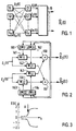
- FIG. 1 represents primary sources Si to Sn constituted for example by voices of passengers in a vehicle, by various sources of noise (engine, bodywork, air circulation through windows, etc.) and by a car radio.
- the primary sources deliver primary signals X i (t). It is observed that these primary signals will mix with each other in the transmission space.
- place sensors C1 to Cn for example microphones, inside the passenger compartment.
- the sensors deliver mixing signals E i (t).
- this may relate to the reception of radio waves emitted by sources Si to Sn and detected by sensors constituted by antennas C1 to Cn.
- the primary signals X i (t) delivered by the transmitters will arrive mixed with each other at the antennas. These will then provide mixing signals E i (t) which are the only signals accessible at the reception level.
- estimates X and i ( t ) i current index varying from 1 to n, corresponding to each source, from the mixing signals E i (t), it is known to use a system 10 source separation.
- the input signals E i ( t ) enter a source separation subset 12 which delivers first estimates X and i ( t ).
- a second subset 14 determines the separation coefficients W i, j from the first estimates X and i ( t ). For this, it calculates correction factors ⁇ W i, j to update the separation coefficients. These are then introduced in the following cycle in the first subset 12 for the determination of the following estimates X and i ( t ).
- W ii ( t 1) W ii ( t ) ⁇ - ⁇ f [ X i ( t )] g [ X i ( t )] - 1 ⁇ (6)
- W ij ( t 1) W ij ( t ) - ⁇ f [ X i ( t )] g [ X j ( t )], i ⁇ j in which ⁇ is a positive adaptation step, f and g being preferably non-linear functions.
- the new values of W ij are loaded into memories of separation coefficients contained in the first subset 12.
- the adaptation rule (6) is used to update the crossed coefficients W 12 and W 21 aimed at eliminating the component X and 2 ( t ) in X 1 ( t ) and the component X and 1 ( t ) in X and 2 ( t ).
- the adaptation rule (5) is used to update the direct coefficients W 11 and W 22 aimed at normalizing the scales of the signals X and 1 ( t ) and X and 2 ( t ) respectively. These direct coefficients adapt themselves to the nature of the signals to be processed.
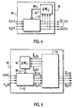
- the mixing signal E 1 ( t ) enters into multipliers 141, 142 and the mixing signal E 2 ( t ) enters into multipliers 143, 144.
- the outputs of the multipliers 141 and 143 are added in an adder 150 while the outputs of multipliers 142 and 144 are added in an adder 151 to deliver the estimates X and 1 ( t ) and X and 2 ( t ) respectively.
- Module 161 receives the estimate X and 1 ( t ) and module 162 receives the estimates X and 1 ( t ) and X and 2 ( t ).
- the modules 161 and 162 respectively calculate the correction factors ⁇ W 11 and ⁇ W 21 according to equations 7 and 8 and deliver as soon as updated separation coefficients W 11 and W 21 .
- a similar processing is carried out in modules 163 and 164 for the correction factors ⁇ W 12 and ⁇ W 22 .
- the invention consists in modifying the system of the prior art represented in FIG. 4, in keeping operations (3) and (4) but in modifying the rules for adapting the separation coefficients. More precisely, instead of using the first estimates X and 1 ( t ) and X and 2 ( t ) to update the coefficients, we pass these signals through specific means which limit their amplitudes from the moment considered. These are second estimates with limited amplitudes which are then used. Thus the modifications provided to the separation coefficients are limited. In this way, the new coefficients gradually converge towards new stable values and no longer diverge.
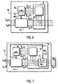
- a third subset 15 is placed at the output of the first subset 12.
- the third subset transforms the first estimates X and 1 ( t ) to X and n ( t ) in second estimates X ⁇ 1 ( t ) to X ⁇ n ( t ) whose amplitudes are normalized with respect to the signal having the maximum amplitude, in absolute value, taken from those included in X and 1 ( t ) to X and n ( t ) at the instant considered.
- This operation is carried out in an amplitude limitation unit 16 (FIG. 6).
- the variations ⁇ W ij are calculated in the same way as in the system of the prior art.
- the invention can also be applied (module 12) to a source separation structure described in the document: "Blind separation of sources, Part I: An adaptive algorithm based on neuromimetic architecture "C.JUTTEN, J. HERAULT, Signal Processing, 24, 1991, pages 1-10.
- the second sub-assembly 14 includes a low-pass filtering unit 141 which filters the correction factors F ij (t) to calculate the variations in coefficients ⁇ W ij to set day the separation coefficients W ij .
- the first estimates will therefore converge towards the same standardized energy. This is not always acceptable in all applications where signals appear non stationary sources. For example, consider the case where source signals are speech signals with periods during which the signals have a high energy (words strong) and periods during which the signals have a weak energy (weak words). In the situation described previously, the first estimates would all have the same high energy in these two situations which is like making a energy leveling.
- Another particular embodiment of the invention relates to the case of two non-stationary signals for which there exists, for a given period, only one non-zero source signal X i ( t ) or more particularly when with two source signals, one of the signals is very high compared to the other.
- this strong source signal will give rise to an estimate (first or second as the case may be) which will appear on the two output channels of the device according to the previous embodiments, that is to say that if alternately signal X 1 ( t ) is strong then the other signal X 2 ( t ) is in turn, the estimate X and 1 ( t ) will appear not only on channel 1 (assigned to signal X 1 ( t )) but also on channel 2. And vice versa when the signal X 2 ( t ) becomes strong.
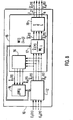
- FIG. 9 represents a particular embodiment of FIG. 8 in the case where there are only two mixing signals E 1 ( t ) and E 2 ( t ).
- the same references are used for FIG. 9 and for FIG. 2.
- the amplitude limitation unit 16 delivers the limited estimates X ⁇ 1 ( t ) and X ⁇ 2 ( t ) to modules 161 to 164 which calculate the new separation coefficients.
- the output subunits 17 1 and 17 2 respectively calculate: and
- the selection unit 19 causes the estimate of one not to be duplicated simultaneously on the channel which does not is not affected.
Description
L'invention concerne un système de séparation de sources pour traiter des signaux d'entrée formés par des mélanges de signaux primaires issus des sources et pour estimer les signaux primaires, le système comprenant un premier sous-ensemble de séparation de sources qui, à l'aide de coefficients de séparation délivre des estimations des signaux primaires, un second sous-ensemble déterminant adaptativement les coefficients de séparation.The invention relates to a system for separating sources for processing input signals formed by mixtures primary signals from sources and to estimate the signals primary, the system comprising a first subset of separation of sources which, using separation coefficients delivers estimates of primary signals, a second subset adaptively determining the separation coefficients.
Il existe des systèmes qui reçoivent sur leurs entrées des signaux qui se présentent sous la forme de signaux de mélange formés par une superposition de contributions résultant de plusieurs signaux sources. Ceci se présente par exemple avec une antenne qui reçoit des signaux provenant de plusieurs émetteurs, ou quand un microphone délivre un signal de parole désiré mélangé à des signaux perturbateurs non désirés. Généralement on désire extraire tous les signaux de source présents dans le mélange, soit parfaitement soit en optimisant un rapport signal/bruit.There are systems that receive on their inputs signals that are in the form of mixing signals formed by a superposition of contributions resulting from several source signals. This occurs for example with a antenna which receives signals from several transmitters, or when a microphone delivers a desired speech signal mixed with unwanted disturbing signals. Generally we want extract all the source signals present in the mixture, ie perfectly either by optimizing a signal / noise ratio.
En utilisant plusieurs capteurs délivrant plusieurs signaux de mélange, on a cherché à obtenir des estimations fiables des signaux de sources. Des techniques connues opèrent avec des signaux de mélange inconnus et avec des signaux de sources inconnus de sorte que les techniques de séparation sont appelées techniques de séparation en aveugle de sources.Using multiple sensors delivering multiple mixing signals, we tried to get reliable estimates source signals. Known techniques operate with unknown mixing signals and with signals from unknown sources so the separation techniques are called techniques blind separation of sources.
Parmi les structures de séparation de sources connues, on peut par exemple citer le document d'art antérieur "Multi-layer neural networks with a local adaptive learning rule for blind separation of source signais", A. CICHOCKI, W. KASPRZAK, S. AMARI, International Symposium on nonlinear theory and its applications (NOLTA'95) LAS VEGAS, Décembre 10-14, 1995, 1C-5, pages 61 à 65.Among the known source separation structures, we can for example cite the prior art document "Multi-layer neural networks with a local adaptive learning rule for blind separation of source signais ", A. CICHOCKI, W. KASPRZAK, S. AMARI, International Symposium on nonlinear theory and its applications (NOLTA'95) LAS VEGAS, December 10-14, 1995, 1C-5, pages 61 to 65.
Ce document concerne des mélanges difficiles à traiter par exemple parce que les signaux de mélange sont très semblables les uns aux autres ou lorsque les signaux de mélange ont des niveaux très différents.This document concerns mixtures that are difficult to process for example because the mixing signals are very similar to each other or when the mixing signals have very different levels.
Néanmoins les structures décrites dans ce document ne conviennent pas lorsque les signaux de sources sont des signaux non stationnaires. Ceci constitue un inconvénient important, car ces types de signaux se rencontrent très souvent dans les applications concrètes telles que le traitement des signaux de paroles ou plus généralement des signaux audio.However, the structures described in this document do not not suitable when the source signals are non-signal stationary. This is a major drawback, because these types of signals are encountered very often in applications concrete such as processing speech signals or more usually audio signals.
Le but de l'invention est de proposer un système de séparation de source qui permette de traiter le cas des signaux non stationnaires même si ces signaux entrent dans la catégorie des mélanges dits difficiles cités précédemment.The object of the invention is to propose a system of source separation which makes it possible to deal with the case of non-signal stationary even if these signals fall into the category of so-called difficult mixtures mentioned above.
Ce but est atteint avec un système de séparation de sources pour traiter des signaux d'entrée formés par des mélanges de signaux primaires issus des sources et pour estimer les signaux primaires, le système comprenant un premier sous-ensemble de séparation de sources ayant des premières entrées reliées aux signaux d'entrée, des secondes entrées pour recevoir des coefficients de séparation et des sorties pour délivrer des premières estimations des signaux primaires, un second sous-ensemble pour déterminer adaptativement les coefficients de séparation caractérisé en ce qu'il comprend un troisième sous-ensemble qui reçoit les premières estimations parmi lesquelles il détecte une estimation maximale possédant un niveau d'amplitude maximal et qui normalise les premières estimations par rapport à l'estimation maximale pour délivrer des secondes estimations lesquelles entrent dans le second sous-ensemble pour le calcul des coefficients de séparation.This goal is achieved with a system of separation of sources for processing input signals formed by mixtures primary signals from sources and to estimate the signals primary, the system comprising a first subset of separation of sources having first inputs connected to input signals, second inputs to receive separation coefficients and outputs to deliver first estimates of primary signals, a second subset to adaptively determine the coefficients of separation characterized in that it comprises a third subset who receives the first estimates among which he detects a maximum estimate with an amplitude level maximum and which normalizes the first estimates compared to the maximum estimate to deliver second estimates which fall into the second subset for the calculation of separation coefficients.
Ainsi lorsque les signaux primaires issus des sources présentent de fortes variations de niveaux d'amplitude au cours d'une période transitoire, il ne peut pas se produire un dépassement temporaire du niveau d'amplitude des secondes estimations pendant cette période transitoire. Le niveau des secondes estimations reste toujours contenu dans une fenêtre d'amplitude déterminée.So when the primary signals from the sources show large variations in amplitude levels during of a transitional period, there cannot be a temporary overshoot of the seconds amplitude level estimates during this transitional period. The level of second estimates always remains in a window of determined amplitude.
Cependant, quand le niveau du signal d'entrée est relativement constant, qu'il soit fort ou faible, les premières estimations qui sont délivrées en sortie présentent un niveau moyen sensiblement semblable en sortie. Ceci signifie que les coefficients de séparation calculés par le système s'adaptent de manière à maintenir les premières estimations délivrées normalisées avec une énergie prédéfinie. Ceci peut constituer un handicap dans certaines applications car on perd ainsi le caractère fort ou faible d'un signal d'entrée. Par exemple dans le cas de signaux de parole, il peut être utile de différencier une voix faible d'une voix forte.However, when the level of the input signal is relatively constant, whether strong or weak, the first estimates that are output have an average level substantially similar at output. This means that separation coefficients calculated by the system adapt from so as to maintain the first estimates delivered standardized with a predefined energy. This can constitute a handicap in certain applications because we lose the strong character or weak of an input signal. For example in the case of signals of speech it can be helpful to differentiate a weak voice from a loud voice.
Pour corriger cet inconvénient, selon l'invention, le troisième sous-ensemble comporte un module de sortie qui divise chaque première estimation par un coefficient de séparation spécifique pour délivrer des troisièmes estimations proportionnelles aux signaux primaires avec un facteur de proportionnalité indépendant desdits signaux primaires.To correct this drawback, according to the invention, the third subset has an output module that divides each first estimate by a separation coefficient specific to issue third estimates proportional to primary signals with a factor of independent proportionality of said primary signals.
Dans certaines applications particulières, il peut apparaítre qu'un signal primaire soit temporairement absent. La situation qui mérite de l'attention est celle de locuteurs s'exprimant alternativement. Il existe donc des moments durant lesquels chaque interlocuteur s'arrête de parler, c'est-à-dire que son signal source est momentanément interrompu pour reprendre quelques instants plus tard. Il faut donc que l'estimation de ce signal absent soit nulle en sortie durant ces périodes. Or dans le cas de signaux primaires nuls ou très faibles, le système de séparation aura tendance à dupliquer sur la sortie inutilisée une des autres estimations non nulles. Pour éviter cette situation, selon l'invention, on munit le troisième sous-ensemble d'un module de sélection qui empêche à une estimation d'être dupliquée sur une voie affectée à un signal primaire absent.In some specific applications, it may appear that a primary signal is temporarily absent. The situation that deserves attention is that of speakers speaking alternately. So there are moments during which each interlocutor stops speaking, i.e. its source signal is momentarily interrupted to resume a few moments later. So the estimation of this signal absent or zero at output during these periods. Gold in the in the case of zero or very weak primary signals, the separation will tend to duplicate on the unused output a other non-zero estimates. To avoid this situation, according to the invention, the third subset is provided with a module selection that prevents an estimate from being duplicated on a channel assigned to an absent primary signal.
Ces différents aspects de l'invention et d'autres encore seront apparents et élucidés à partir des modes de réalisation décrits ci-après.These different aspects of the invention and others still will be apparent and elucidated from the modes of realization described below.
L'invention sera mieux comprise à l'aide des figures
suivantes données à titre d'exemples non limitatifs qui
représentent:
La figure 1 représente des sources primaires Si à Sn constituées par exemple par des voix de passagers dans un véhicule, par des sources de bruits divers (moteur, carrosserie, circulation d'air par les fenêtres, etc) et par un autoradio. Les sources primaires délivrent des signaux primaires Xi(t). On observe que ces signaux primaires vont se mélanger les uns aux autres dans l'espace de transmission. Pour identifier les voix, on place des capteurs C1 à Cn, par exemple des microphones, à l'intérieur de l'habitacle. Les capteurs délivrent des signaux de mélange Ei(t).FIG. 1 represents primary sources Si to Sn constituted for example by voices of passengers in a vehicle, by various sources of noise (engine, bodywork, air circulation through windows, etc.) and by a car radio. The primary sources deliver primary signals X i (t). It is observed that these primary signals will mix with each other in the transmission space. To identify the voices, place sensors C1 to Cn, for example microphones, inside the passenger compartment. The sensors deliver mixing signals E i (t).
De manière analogue, cela peut concerner la réception
d'ondes hertziennes émises par des sources Si à Sn et détectées par
des capteurs constitués par des antennes C1 à Cn. Dans l'air, les
signaux primaires Xi(t) délivrés par les émetteurs vont arriver
mélangés les uns aux autres au niveau des antennes. Celles-ci vont
alors fournir des signaux de mélange Ei(t) qui sont les seuls
signaux accessibles au niveau de la réception. Pour obtenir des
signaux estimés, dits estïmations X andi (t), i indice courant variant
de 1 à n, correspondant à chaque source, à partir des signaux de
mélange Ei(t), il est connu d'utiliser un système 10 de séparation
de sources.Similarly, this may relate to the reception of radio waves emitted by sources Si to Sn and detected by sensors constituted by antennas C1 to Cn. In the air, the primary signals X i (t) delivered by the transmitters will arrive mixed with each other at the antennas. These will then provide mixing signals E i (t) which are the only signals accessible at the reception level. To obtain estimated signals, called estimates X and i ( t ), i current index varying from 1 to n, corresponding to each source, from the mixing signals E i (t), it is known to use a
Selon l'art antérieur connu (figure 4). les signaux
d'entrée Ei (t) entrent dans un sous-ensemble 12 de séparation de
sources qui délivre des premières estimations X andi (t). Un second
sous-ensemble 14 détermine des coefficients de séparation Wi,j à
partir des premières estimations X andi (t). Pour cela il calcule des
facteurs de correction ΔWi,j pour mettre à jour les coefficients
de séparation. Ceux-ci sont alors introduits au cycle suivant dans
le premier sous-ensemble 12 pour la détermination des estimations
suivantes X andi (t).According to the known prior art (Figure 4). the input signals E i ( t ) enter a
Pour des raisons de clarté on va décrire un cas simple
d'un système à structure directe comportant une seule couche de
traitement pour séparer deux signaux de sources X 1(t) et X 2(t)
selon l'art antérieur cité (figure 2). Deux capteurs délivrent des
signaux de mélange E 1(t) et E 2(t). Ces signaux sont reliés aux
signaux primaires par les relations suivantes:
Le schéma de l'art antérieur représenté sur la figure 2
permet de déterminer les estimations X and 1(t) et X and 2(t) à partir des
signaux de mélange E 1(t) et E 2(t) à partir des relations:
Pour mettre à jour les coefficients de séparation, on
peut appliquer les règles d'adaptation suivantes:
Les nouvelles valeurs de Wij sont chargées dans des
mémoires de coefficients de séparation contenues dans le premier
sous-ensemble 12.The new values of W ij are loaded into memories of separation coefficients contained in the
La règle d'adaptation (6) est utilisée pour mettre à jour les coefficients croisés W12 et W21 visant à éliminer la composante X and 2(t) dans X 1(t) et la composante X and 1(t) dans X and 2(t).The adaptation rule (6) is used to update the crossed coefficients W 12 and W 21 aimed at eliminating the component X and 2 ( t ) in X 1 ( t ) and the component X and 1 ( t ) in X and 2 ( t ).
La règle d'adaptation (5) est utilisée pour mettre à jour les coefficients directs W11 et W22 visant à normaliser les échelles des signaux X and 1(t) et X and 2(t) respectivement. Ces coefficients directs s'adaptent eux-mêmes à la nature des signaux à traiter.The adaptation rule (5) is used to update the direct coefficients W 11 and W 22 aimed at normalizing the scales of the signals X and 1 ( t ) and X and 2 ( t ) respectively. These direct coefficients adapt themselves to the nature of the signals to be processed.
Dans le cas de deux signaux représenté sur la figure 2,
le signal de mélange E 1(t) entre dans des multiplieurs 141, 142 et
le signal de mélange E 2(t) entre dans des multiplieurs 143, 144.
Les sorties des multiplieurs 141 et 143 sont additionnées dans un
additionneur 150 tandis que les sorties des multiplieurs 142 et 144
sont additionnées dans un additionneur 151 pour délivrer
respectivement les estimations X and 1(t) et X and 2(t). Le module 161
reçoit l'estimation X and 1(t) et le module 162 reçoit les estimations
X and 1(t) et X and 2(t). Les modules 161 et 162 calculent respectivement
les facteurs de correction ΔW 11 et ΔW 21 selon les équations 7 et
8 et délivrent dès coefficients de séparation mis à jour W11 et W21.
Un traitement analogue est effectué dans les modules 163 et 164
pour les facteurs de correction ΔW 12 et ΔW 22.In the case of two signals represented in FIG. 2, the mixing signal E 1 ( t ) enters into
Considérons le cas de signaux de sources ayant une échelle relativement constante (ou une enveloppe constante) durant une période donnée, les coefficients de mélange aij étant par ailleurs constants ou très lentement variables. Dans ce cas les coefficients W11 et W22 convergent vers des valeurs relativement constantes assurant des énergies prédéfinies aux estimations X and 1(t) et X and 2(t). Dans le cas où f(x)=x3 et g(x)=x, l'énergie prédéfinie s'exprime par <X and 4>. Cette valeur prédéfinie est par exemple égale à 1 dans le cas des équations 5 et 6. La remise à jour des coefficients de séparation est effectuée à chaque unité de temps t, t+1, t+2...Let us consider the case of signals from sources having a relatively constant scale (or a constant envelope) during a given period, the mixing coefficients a ij being otherwise constant or very slowly variable. In this case the coefficients W 11 and W 22 converge towards relatively constant values ensuring predefined energies with the estimates X and 1 ( t ) and X and 2 ( t ). In the case where f (x) = x 3 and g (x) = x, the predefined energy is expressed by < X and 4 >. This predefined value is for example equal to 1 in the case of equations 5 and 6. The updating of the separation coefficients is carried out at each time unit t, t + 1, t + 2 ...
Lorsque l'échelle des signaux de sources varie brusquement très fortement ceci provoque une variation rapide et forte des signaux de mélange. Ce cas est représenté sur la figure 3. Au point A, il y a une brusque variation dans l'enveloppe des signaux de mélange E(t). Néanmoins aux instants immédiatement suivants, d'après l'algorithme de mise à jour précédent, les coefficients de séparation W11 et W22 vont conserver des valeurs proches de celles qu'ils avaient juste avant cette forte augmentation car leur adaptation nécessite une durée s'étalant sur quelques centaines à quelques milliers d'unités de temps. Donc la forte augmentation d'échelle des signaux de mélange provoque aussi une forte augmentation des estimations X and 1(t) et X and 2(t) par les relations (3) et (4) qui à son tour entraíne que les modifications des coefficients W11 et W22 deviennent élevées à cause de la relation (5). Ainsi les valeurs de ces coefficients de séparation deviennent très élevées d'où un fort accroissement des signaux de sortie occasionnant un nouvel accroissement des coefficients de séparation faisant que les sorties peuvent diverger dans le cas des signaux non stationnaires.When the scale of the source signals varies abruptly very strongly this causes a rapid and strong variation of the mixing signals. This case is shown in Figure 3. At point A, there is an abrupt variation in the envelope of the mixing signals E (t). However, at the immediately following moments, according to the previous updating algorithm, the separation coefficients W 11 and W 22 will keep values close to those they had just before this sharp increase because their adaptation requires a duration s spanning a few hundred to a few thousand time units. So the large increase in scale of the mixing signals also causes a large increase in the estimates X and 1 ( t ) and X and 2 ( t ) by the relations (3) and (4) which in turn results in the modifications of the coefficients W 11 and W 22 become high due to the relation (5). Thus the values of these separation coefficients become very high, hence a strong increase in the output signals causing a further increase in the separation coefficients so that the outputs can diverge in the case of non-stationary signals.
L'invention consiste à modifier le système de l'art antérieur représenté sur la figure 4, à conserver les opérations (3) et (4) mais à modifier les règles d'adaptation des coefficients de séparation. Plus précisément, au lieu d'utiliser les premières estimations X and 1(t) et X and 2(t) pour mettre à jour les coefficients, on fait passer ces signaux dans des moyens spécifiques qui limitent leurs amplitudes d'après l'instant considéré. Ce sont des secondes estimations à amplitudes limitées qui sont alors utilisées. Ainsi les modifications fournies aux coefficients de séparation sont bornées. De cette manière, les nouveaux coefficients convergent progressivement vers de nouvelles valeurs stables et ne divergent plus.The invention consists in modifying the system of the prior art represented in FIG. 4, in keeping operations (3) and (4) but in modifying the rules for adapting the separation coefficients. More precisely, instead of using the first estimates X and 1 ( t ) and X and 2 ( t ) to update the coefficients, we pass these signals through specific means which limit their amplitudes from the moment considered. These are second estimates with limited amplitudes which are then used. Thus the modifications provided to the separation coefficients are limited. In this way, the new coefficients gradually converge towards new stable values and no longer diverge.
Ce mode de réalisation est représenté sur les figures 5
et 6. Un troisième sous-ensemble 15 est placé en sortie du premier
sous-ensemble 12. Le troisième sous-ensemble transforme les
premières estimations X and 1(t) à X andn (t) en des secondes estimations
X ˙ 1(t) à X ˙n (t) dont les amplitudes sont normalisées par rapport au
signal ayant l'amplitude maximale, en valeur absolue, pris parmi
ceux compris dans X and 1(t) à X andn (t) à l'instant considéré. Cette
opération est réalisée dans une unité 16 de limitation d'amplitude
(figure 6).This embodiment is represented in FIGS. 5 and 6. A
A chaque instant, on modifie les coefficients de séparation de la manière suivante:
- on calcule les sorties X andi (t) du système de l'art antérieur;
- on calcule le maximum M de leurs valeurs absolues soit: M = max|X andi (t)|, i=1...n;
- on définit une valeur de seuil β>0 correspondant à la valeur maximale autorisée pour les valeurs absolues des signaux limités X ˙i (t). Ce seuil est choisi librement et définit l'ampleur de la limitation désirée.
- the outputs X and i ( t ) of the system of the prior art are calculated;
- the maximum M of their absolute values is calculated, ie: M = max | X and i ( t ) |, i = 1 ... n ;
- a threshold value β> 0 is defined corresponding to the maximum authorized value for the absolute values of the limited signals X ˙ i ( t ). This threshold is freely chosen and defines the extent of the desired limitation.
A l'instant considéré, on compare M à β et on réalise la limitation telle que:
- si M <=β, les signaux X andi (t) ont une amplitude assez
faible, donc il n'y a pas lieu de limiter, d'où:
- si M>β, au moins un signal a une amplitude forte,
donc on limite tous les signaux avec le même facteur de réduction,
d'où:
- if M <= β, the signals X and i ( t ) have a fairly low amplitude, so there is no need to limit, hence:
- if M> β, at least one signal has a strong amplitude, so we limit all the signals with the same reduction factor, hence:
Les variations ΔWij sont calculées de la même façon
que dans le système de l'art antérieur. Le second sous-ensemble 14
détermine les modifications à apporter aux coefficients de
séparation Wij à partir des secondes estimations X ˙ 1(t) à X ˙n (t)
c'est-à-dire:
L'invention peut être également appliquée (module 12) à une structure de séparation de sources décrite dans le document: "Blind separation of sources, Part I: An adaptive algorithm based on neuromimetic architecture" C.JUTTEN, J. HERAULT, Signal Processing, 24, 1991, pages 1-10.The invention can also be applied (module 12) to a source separation structure described in the document: "Blind separation of sources, Part I: An adaptive algorithm based on neuromimetic architecture "C.JUTTEN, J. HERAULT, Signal Processing, 24, 1991, pages 1-10.
Une seconde possibilité permettant de limiter la
divergence des signaux de sortie consiste à calculer les facteurs
de correction:
Dans ce cas, chaque coefficient de séparation est
modifié d'une quantité ΔWij (t) qui résulte d'un filtrage passe-bas
d'ordre 1 c'est-à-dire:
L'opération de normalisation en énergie réalisée sur les premières estimations délivrées par le premier sous-ensemble a pour conséquence de maintenir ces premières estimations voisines d'une énergie prédéfinie, et ceci quelle que soit l'échelle des signaux de sources. Les premières estimations vont donc converger vers une même énergie normalisée. Ceci n'est pas toujours acceptable dans toutes les applications où apparaissent des signaux de source non stationnaires. Par exemple, considérons le cas où les signaux de source sont des signaux de paroles avec des périodes durant lesquelles les signaux possèdent une énergie élevée (paroles fortes) et des périodes durant lesquelles les signaux possèdent une énergie faible (paroles faibles). Dans la situation décrite précédemment, les premières estimations auraient toutes la même énergie élevée dans ces deux situations ce qui revient à faire un nivellement d'énergie.The energy standardization operation carried out on the first estimates issued by the first subset a as a consequence of maintaining these first close estimates of a predefined energy, and this whatever the scale of source signals. The first estimates will therefore converge towards the same standardized energy. This is not always acceptable in all applications where signals appear non stationary sources. For example, consider the case where source signals are speech signals with periods during which the signals have a high energy (words strong) and periods during which the signals have a weak energy (weak words). In the situation described previously, the first estimates would all have the same high energy in these two situations which is like making a energy leveling.
Pour remédier à cet effet, selon l'invention (figure 7)
on réalise un post-traitement sur les premières estimations X andi (t).
Pour cela chaque première estimation X andi (t) de rang i est divisée
par le coefficient de séparation Wii correspondant à son rang,
apparaissant dans les équations 3 et 4. Ceci s'apparente à une
dénormalisation ou à un contrôle auto-adaptatif du gain. On observe
aisément que les troisièmes estimations ![]()
![]()
Donc les étapes du traitement consistent d'abord à
multiplier les signaux de mélange par les coefficients de
séparation Wij, puis à délivrer les premières estimations
normalisées X andi (t) et ensuite à les diviser par les mêmes
coefficients de séparation Wii pour obtenir des troisièmes
estimations dénormalisées
Un autre mode particulier de réalisation de l'invention
concerne le cas de deux signaux non stationnaires pour lesquels il
n'existe, pendant une période donnée, qu'un seul signal de source
Xi (t) non nul ou plus particulièrement lorsqu'avec deux signaux de
sources, un des signaux est très élevé par rapport à l'autre. Dans
ce cas ce signal de source fort va donner lieu à une estimation
(première ou seconde selon le cas) qui va apparaítre sur les deux
voies de sortie du dispositif selon les modes de réalisation
précédents, c'est-à-dire que si alternativement le signal X 1(t)
est fort puis l'autre signal X 2(t) l'est à son tour, l'estimation
X and 1(t) va apparaítre non seulement sur la voie 1 (affectée au
signal X 1(t)) mais aussi sur la voie 2. Et inversement lorsque le
signal X 2(t) devient fort.Another particular embodiment of the invention relates to the case of two non-stationary signals for which there exists, for a given period, only one non-zero source signal X i ( t ) or more particularly when with two source signals, one of the signals is very high compared to the other. In this case this strong source signal will give rise to an estimate (first or second as the case may be) which will appear on the two output channels of the device according to the previous embodiments, that is to say that if alternately signal X 1 ( t ) is strong then the other signal X 2 ( t ) is in turn, the estimate X and 1 ( t ) will appear not only on channel 1 (assigned to signal X 1 ( t )) but also on
Pour traiter ce cas, le troisième sous-ensemble 15 dispose en sortie d'un module de sélection 19 qui empêche à une estimation d'être dupliquée sur une voie affectée à un signal de source absent. Le module de sélection 19 est connecté en sortie du module de sortie 17 (figure 7) de manière à obtenir le schéma représenté sur la figure 8. Ce module 19 opère de la manière suivante:
- si les deux signaux qui arrivent sur ses entrées sont
corrélés, alors le
module 19 délivre le signal qui a la plus forte amplitude et garde l'autre sortie à zéro. - si les deux signaux ne sont pas corrélés, le traitement est effectué indépendamment du bloc comme cela a été décrit précédemment.
- if the two signals arriving at its inputs are correlated, then the
module 19 delivers the signal which has the highest amplitude and keeps the other output at zero. - if the two signals are not correlated, the processing is carried out independently of the block as described above.
Pour mettre en oeuvre la fonction de ce module 19 il peut s'agir:
- d'un sous-bloc qui détecte la proportionnalité des
deux signaux d'entrée de
ce module 19, basée par exemple sur un test de corrélation qui active le multiplexage correct des signaux qui lui arrivent; - ou d'un module de séparation de sources analogue à celui servant à la séparation de sources fourni dans la description ou à celui décrit dans le document de C. Jutten et J. Hérault cité précédemment. Mais dans ce cas, les signaux qui sont à traiter ne sont pas des signaux de mélanges "difficiles à traiter" car il s'agit à ce niveau de signaux qui sont soit corrélés, soit non corrélés.
- a sub-block which detects the proportionality of the two input signals of this
module 19, based for example on a correlation test which activates the correct multiplexing of the signals which arrive at it; - or a source separation module similar to that used for source separation provided in the description or that described in the document by C. Jutten and J. Hérault cited above. But in this case, the signals which are to be processed are not signals of mixtures "difficult to process" because they are at this level signals which are either correlated or uncorrelated.
Le cas avec deux signaux est donné à titre d'exemple, la sélection pouvant s'opérer entre plus de deux signaux.The case with two signals is given as an example, the selection being possible between more than two signals.
La figure 9 représente un mode particulier de
réalisation de la figure 8 dans le cas où il n'existe que deux
signaux de mélange E 1(t) et E 2(t). Les mêmes références sont
utilisées pour la figure 9 et pour la figure 2. L'unité 16 de
limitation d'amplitude délivre les estimations limitées X ˙ 1(t) et
X ˙ 2(t) aux modules 161 à 164 qui calculent les nouveaux
coefficients de séparation. Les sous-unités de sortie 171 et 172
calculent respectivement:
![]()
![]()
![]()
![]()
Quand l'un des signaux E 1(t) ou E 2(t) est
momentanément absent ou très faible, l'unité de sélection 19 fait
que l'estimation de l'un ne soit pas dupliquée simultanément sur la
voie qui ne lui est pas affectée.When one of the signals E 1 ( t ) or E 2 ( t ) is momentarily absent or very weak, the
Claims (4)
- A source separation system (10) for processing input signals (E(t)) formed by mixtures of primary signals (Xi(t)) originating from various sources (S1-Sn) and for estimating the primary signals, the system comprising a first source separation sub-assembly (12) which has first inputs connected to the input signals, second inputs for receiving separation coefficients (Wij) and outputs for producing first estimates (X and i (t)) of the primary signals, a second sub-assembly (14) for adaptively determining the separation coefficients, characterized in that the source separation system (10) comprises a third sub-assembly (15) which receives the first estimates among which it detects a maximum estimate with a maximum amplitude level and which standardizes the first estimates relative to the maximum estimate to produce second estimates (X ˙(t)) which enter the second sub-assembly for the calculation of the separation coefficients.
- The system as claimed in claim 1, characterized in that the third sub-assembly comprises an output module (17) which divides each first estimate (X and i(t)) by a specific separation coefficient (Wii) to produce third estimates (i(t)) which are proportional to the primary signals with proportionality factors which are independent of said primary signals (Xi (t)).

- A system as claimed in one of the claims 1 or 2, characterized in that the third sub-assembly (15) has output channels (1-n) assigned specifically to each estimate, the third sub-assembly comprising a selection module (19) which prevents an estimate being duplicated on a channel assigned to a primary signal that is absent.
- A system as claimed in one of the claims 1 to 3, characterized in that the second sub-assembly (14) has filter means (141) for filtering the separation coefficients (Wij).
Applications Claiming Priority (2)
| Application Number | Priority Date | Filing Date | Title |
|---|---|---|---|
| FR9701881 | 1997-02-18 | ||
| FR9701881A FR2759824A1 (en) | 1997-02-18 | 1997-02-18 | SYSTEM FOR SEPARATING NON-STATIONARY SOURCES |
Publications (2)
| Publication Number | Publication Date |
|---|---|
| EP0860944A1 EP0860944A1 (en) | 1998-08-26 |
| EP0860944B1 true EP0860944B1 (en) | 2003-07-16 |
Family
ID=9503853
Family Applications (1)
| Application Number | Title | Priority Date | Filing Date |
|---|---|---|---|
| EP98200391A Expired - Lifetime EP0860944B1 (en) | 1997-02-18 | 1998-02-09 | Separation system for non-stationary sources |
Country Status (5)
| Country | Link |
|---|---|
| US (1) | US5999956A (en) |
| EP (1) | EP0860944B1 (en) |
| JP (1) | JPH10253385A (en) |
| DE (1) | DE69816354T2 (en) |
| FR (1) | FR2759824A1 (en) |
Families Citing this family (23)
| Publication number | Priority date | Publication date | Assignee | Title |
|---|---|---|---|---|
| US6473404B1 (en) | 1998-11-24 | 2002-10-29 | Connect One, Inc. | Multi-protocol telecommunications routing optimization |
| US6016307A (en) | 1996-10-31 | 2000-01-18 | Connect One, Inc. | Multi-protocol telecommunications routing optimization |
| US6335927B1 (en) | 1996-11-18 | 2002-01-01 | Mci Communications Corporation | System and method for providing requested quality of service in a hybrid network |
| US6731625B1 (en) | 1997-02-10 | 2004-05-04 | Mci Communications Corporation | System, method and article of manufacture for a call back architecture in a hybrid network with support for internet telephony |
| SE521024C2 (en) * | 1999-03-08 | 2003-09-23 | Ericsson Telefon Ab L M | Method and apparatus for separating a mixture of source signals |
| JP2001053654A (en) * | 1999-08-16 | 2001-02-23 | Matsushita Electric Ind Co Ltd | Signal separating device, signal separation method and recording medium |
| US6654719B1 (en) * | 2000-03-14 | 2003-11-25 | Lucent Technologies Inc. | Method and system for blind separation of independent source signals |
| JP3725418B2 (en) * | 2000-11-01 | 2005-12-14 | インターナショナル・ビジネス・マシーンズ・コーポレーション | Signal separation method, image processing apparatus, and storage medium for restoring multidimensional signal from image data mixed with a plurality of signals |
| JP4028680B2 (en) * | 2000-11-01 | 2007-12-26 | インターナショナル・ビジネス・マシーンズ・コーポレーション | Signal separation method for restoring original signal from observation data, signal processing device, mobile terminal device, and storage medium |
| US7383178B2 (en) * | 2002-12-11 | 2008-06-03 | Softmax, Inc. | System and method for speech processing using independent component analysis under stability constraints |
| US6954530B2 (en) * | 2003-07-09 | 2005-10-11 | Utah State University | Echo cancellation filter |
| US7099821B2 (en) * | 2003-09-12 | 2006-08-29 | Softmax, Inc. | Separation of target acoustic signals in a multi-transducer arrangement |
| DE102004053790A1 (en) * | 2004-11-08 | 2006-05-18 | Siemens Audiologische Technik Gmbh | Method for generating stereo signals for separate sources and corresponding acoustic system |
| US7464029B2 (en) * | 2005-07-22 | 2008-12-09 | Qualcomm Incorporated | Robust separation of speech signals in a noisy environment |
| WO2007103037A2 (en) * | 2006-03-01 | 2007-09-13 | Softmax, Inc. | System and method for generating a separated signal |
| US20080208538A1 (en) * | 2007-02-26 | 2008-08-28 | Qualcomm Incorporated | Systems, methods, and apparatus for signal separation |
| US8160273B2 (en) * | 2007-02-26 | 2012-04-17 | Erik Visser | Systems, methods, and apparatus for signal separation using data driven techniques |
| US8175291B2 (en) * | 2007-12-19 | 2012-05-08 | Qualcomm Incorporated | Systems, methods, and apparatus for multi-microphone based speech enhancement |
| US8321214B2 (en) * | 2008-06-02 | 2012-11-27 | Qualcomm Incorporated | Systems, methods, and apparatus for multichannel signal amplitude balancing |
| JP5544110B2 (en) * | 2009-03-31 | 2014-07-09 | 鹿島建設株式会社 | Reference signal processing device, active noise control device having reference signal processing device, and active noise control system |
| JP5565593B2 (en) * | 2009-10-01 | 2014-08-06 | 日本電気株式会社 | Signal processing method, signal processing apparatus, and signal processing program |
| US9357307B2 (en) | 2011-02-10 | 2016-05-31 | Dolby Laboratories Licensing Corporation | Multi-channel wind noise suppression system and method |
| US9966088B2 (en) | 2011-09-23 | 2018-05-08 | Adobe Systems Incorporated | Online source separation |
Family Cites Families (4)
| Publication number | Priority date | Publication date | Assignee | Title |
|---|---|---|---|---|
| US3696203A (en) * | 1970-06-03 | 1972-10-03 | Philco Ford Corp | Adaptive modem receiver |
| US5293405A (en) * | 1991-10-31 | 1994-03-08 | International Business Machines Corp. | Adaptive equalization and regeneration system |
| IL101556A (en) * | 1992-04-10 | 1996-08-04 | Univ Ramot | Multi-channel signal separation using cross-polyspectra |
| US5652541A (en) * | 1993-11-23 | 1997-07-29 | Motorola, Inc. | Data demodulator employing decision feedback for reference parameter recovery and method used therin |
-
1997
- 1997-02-18 FR FR9701881A patent/FR2759824A1/en not_active Withdrawn
-
1998
- 1998-02-05 US US09/018,979 patent/US5999956A/en not_active Expired - Lifetime
- 1998-02-09 DE DE69816354T patent/DE69816354T2/en not_active Expired - Fee Related
- 1998-02-09 EP EP98200391A patent/EP0860944B1/en not_active Expired - Lifetime
- 1998-02-18 JP JP10035601A patent/JPH10253385A/en not_active Abandoned
Also Published As
| Publication number | Publication date |
|---|---|
| JPH10253385A (en) | 1998-09-25 |
| DE69816354D1 (en) | 2003-08-21 |
| FR2759824A1 (en) | 1998-08-21 |
| DE69816354T2 (en) | 2004-05-27 |
| US5999956A (en) | 1999-12-07 |
| EP0860944A1 (en) | 1998-08-26 |
Similar Documents
| Publication | Publication Date | Title |
|---|---|---|
| EP0860944B1 (en) | Separation system for non-stationary sources | |
| EP1830349B1 (en) | Method of noise reduction of an audio signal | |
| EP2293594B1 (en) | Method for filtering lateral non stationary noise for a multi-microphone audio device | |
| EP2430825B1 (en) | Method for selecting a microphone among a plurality of microphones in a speech processing system such as a hands-free telephone device operating in a noisy environment | |
| EP1154405B1 (en) | Method and device for speech recognition in surroundings with varying noise levels | |
| EP2057835B1 (en) | Method of reducing the residual acoustic echo after echo removal in a hands-free device | |
| EP2122607B1 (en) | Method for the active reduction of sound disturbance | |
| EP2772916B1 (en) | Method for suppressing noise in an audio signal by an algorithm with variable spectral gain with dynamically adaptive strength | |
| EP1401183B1 (en) | Method and device for echo cancellation | |
| FR2771542A1 (en) | FREQUENTIAL FILTERING METHOD APPLIED TO NOISE NOISE OF SOUND SIGNALS USING A WIENER FILTER | |
| EP0867856A1 (en) | Method and apparatus for vocal activity detection | |
| WO2006049260A1 (en) | Signal processing method, signal processing device, and signal processing program | |
| FR3012928A1 (en) | MODIFIERS BASED ON EXTERNALLY ESTIMATED SNR FOR INTERNAL MMSE CALCULATIONS | |
| EP0856832A1 (en) | Word recognition method and device | |
| EP0729037B1 (en) | System for estimating received signals in the form of mixed signals | |
| EP2469707B1 (en) | Automatic gain control device for satellite positioning receivers | |
| EP1518394B1 (en) | Echo processing devices for single-channel or multichannel communication systems | |
| EP1940139B1 (en) | Control of echo suppression filters | |
| FR2530899A1 (en) | SYSTEM AND DEVICE FOR TRANSMITTING SPEECH SIGNALS OR IDENTICAL SIGNALS FOR DIFFERENTIALLY MODULATED PULSED TRANSMISSION | |
| EP3192073B1 (en) | Discrimination and attenuation of pre-echoes in a digital audio signal | |
| EP1277372B1 (en) | Reception system for multisensor antenna | |
| FR2786308A1 (en) | Telephone communications/civil/military aircraft noisy signal present speech having learning phase determining minimal vector distance with predetermined value added after spectral energy calculation. | |
| EP0673113A1 (en) | System for characterization of signal sources | |
| FR2769117A1 (en) | LEARNING PROCESS IN A SPEECH RECOGNITION SYSTEM | |
| EP1990922B1 (en) | Receiver circuit |
Legal Events
| Date | Code | Title | Description |
|---|---|---|---|
| PUAI | Public reference made under article 153(3) epc to a published international application that has entered the european phase |
Free format text: ORIGINAL CODE: 0009012 |
|
| AK | Designated contracting states |
Kind code of ref document: A1 Designated state(s): DE FR GB |
|
| 17P | Request for examination filed |
Effective date: 19990226 |
|
| AKX | Designation fees paid |
Free format text: DE FR GB |
|
| RBV | Designated contracting states (corrected) |
Designated state(s): DE FR GB |
|
| GRAH | Despatch of communication of intention to grant a patent |
Free format text: ORIGINAL CODE: EPIDOS IGRA |
|
| GRAH | Despatch of communication of intention to grant a patent |
Free format text: ORIGINAL CODE: EPIDOS IGRA |
|
| GRAA | (expected) grant |
Free format text: ORIGINAL CODE: 0009210 |
|
| AK | Designated contracting states |
Designated state(s): DE FR GB |
|
| REG | Reference to a national code |
Ref country code: GB Ref legal event code: FG4D Free format text: NOT ENGLISH |
|
| REF | Corresponds to: |
Ref document number: 69816354 Country of ref document: DE Date of ref document: 20030821 Kind code of ref document: P |
|
| GBT | Gb: translation of ep patent filed (gb section 77(6)(a)/1977) | ||
| REG | Reference to a national code |
Ref country code: GB Ref legal event code: 746 Effective date: 20030807 |
|
| REG | Reference to a national code |
Ref country code: FR Ref legal event code: D6 |
|
| PLBE | No opposition filed within time limit |
Free format text: ORIGINAL CODE: 0009261 |
|
| STAA | Information on the status of an ep patent application or granted ep patent |
Free format text: STATUS: NO OPPOSITION FILED WITHIN TIME LIMIT |
|
| 26N | No opposition filed |
Effective date: 20040419 |
|
| PGFP | Annual fee paid to national office [announced via postgrant information from national office to epo] |
Ref country code: GB Payment date: 20070223 Year of fee payment: 10 |
|
| PGFP | Annual fee paid to national office [announced via postgrant information from national office to epo] |
Ref country code: DE Payment date: 20070410 Year of fee payment: 10 |
|
| PGFP | Annual fee paid to national office [announced via postgrant information from national office to epo] |
Ref country code: FR Payment date: 20080227 Year of fee payment: 11 |
|
| GBPC | Gb: european patent ceased through non-payment of renewal fee |
Effective date: 20080209 |
|
| PG25 | Lapsed in a contracting state [announced via postgrant information from national office to epo] |
Ref country code: DE Free format text: LAPSE BECAUSE OF NON-PAYMENT OF DUE FEES Effective date: 20080902 |
|
| PG25 | Lapsed in a contracting state [announced via postgrant information from national office to epo] |
Ref country code: GB Free format text: LAPSE BECAUSE OF NON-PAYMENT OF DUE FEES Effective date: 20080209 |
|
| REG | Reference to a national code |
Ref country code: FR Ref legal event code: ST Effective date: 20091030 |
|
| PG25 | Lapsed in a contracting state [announced via postgrant information from national office to epo] |
Ref country code: FR Free format text: LAPSE BECAUSE OF NON-PAYMENT OF DUE FEES Effective date: 20090302 |