EP0852182B1 - Ink Ribbon cartridge - Google Patents
Ink Ribbon cartridge Download PDFInfo
- Publication number
- EP0852182B1 EP0852182B1 EP97122870A EP97122870A EP0852182B1 EP 0852182 B1 EP0852182 B1 EP 0852182B1 EP 97122870 A EP97122870 A EP 97122870A EP 97122870 A EP97122870 A EP 97122870A EP 0852182 B1 EP0852182 B1 EP 0852182B1
- Authority
- EP
- European Patent Office
- Prior art keywords
- section
- spindles
- ink ribbon
- spindle
- cover
- Prior art date
- Legal status (The legal status is an assumption and is not a legal conclusion. Google has not performed a legal analysis and makes no representation as to the accuracy of the status listed.)
- Expired - Lifetime
Links
Images


Classifications
-
- B—PERFORMING OPERATIONS; TRANSPORTING
- B41—PRINTING; LINING MACHINES; TYPEWRITERS; STAMPS
- B41J—TYPEWRITERS; SELECTIVE PRINTING MECHANISMS, i.e. MECHANISMS PRINTING OTHERWISE THAN FROM A FORME; CORRECTION OF TYPOGRAPHICAL ERRORS
- B41J32/00—Ink-ribbon cartridges
-
- B—PERFORMING OPERATIONS; TRANSPORTING
- B41—PRINTING; LINING MACHINES; TYPEWRITERS; STAMPS
- B41J—TYPEWRITERS; SELECTIVE PRINTING MECHANISMS, i.e. MECHANISMS PRINTING OTHERWISE THAN FROM A FORME; CORRECTION OF TYPOGRAPHICAL ERRORS
- B41J17/00—Mechanisms for manipulating page-width impression-transfer material, e.g. carbon paper
- B41J17/22—Supply arrangements for webs of impression-transfer material
- B41J17/24—Webs supplied from reels or spools attached to the machine
-
- B—PERFORMING OPERATIONS; TRANSPORTING
- B41—PRINTING; LINING MACHINES; TYPEWRITERS; STAMPS
- B41J—TYPEWRITERS; SELECTIVE PRINTING MECHANISMS, i.e. MECHANISMS PRINTING OTHERWISE THAN FROM A FORME; CORRECTION OF TYPOGRAPHICAL ERRORS
- B41J17/00—Mechanisms for manipulating page-width impression-transfer material, e.g. carbon paper
- B41J17/32—Detachable carriers or holders for impression-transfer material mechanism
Description
- The present invention relates to an ink ribbon cartridge containing a replaceable wide ink ribbon.
- Generally an ink ribbon cartridge is used because of its simplicity of handling when a thermal printer is used to print on common printing paper. However, when a thermal printer (e.g., a line printer) uses a large ink ribbon cartridge, it becomes uneconomical if the whole cartridge thrown away after use. To obviate this drawback, the ink ribbon alone is replaced.
- For this type of ink ribbon, there is employed an ink ribbon including a band-like sheet comprising a resin film with a layer of ink formed on one side of the ribbon and wound around a pair of paper spools. A prior art ink ribbon cartridge using this type of ink ribbon was constructed such that, at the time of ink ribbon replacement, the cover is opened, the used ink ribbon is taken out, and four spindles inserted in both ends of a pair of paper spools of the ink ribbon are removed and then placed in both ends of one pair of paper spools of a new ink ribbon. After the insertion of the new ink ribbon into the cover, the cover is closed. Subsequently, the ink ribbon cartridge is mounted in a printer or a facsimile system as supported by a spindle on bearings that transmit the torque to the paper spools through the spindles, thereby winding the sheet around the paper spool.
- However, the above-described prior art ink ribbon cartridge is of such a structure that any one of the four spindles can be inserted into either of both ends of a pair of paper spools. In addition, in any combination of spindles and spools, the ink ribbon is inserted into the cover to allow the cover to close. Therefore, failures in printing due to improper mounting of the ink ribbon often occurred.
- That is, since a layer of ink is formed on one side of the sheet, the ink can not be transferred to a recording paper if the sheet is mounted with the wrong side out. Also, if the direction of winding is reversed, the sheet can not be wound up, resulting in a failure in printing.
- From
EP 0 435 108 A an ink ribbon cartridge according to the preamble ofclaim 1 is known. In particular, a cover is formed for covering the spools and the spindles. The cover comprises four round holes for receiving the four spindles. The holes have the same shape. - From JP 05-270089 A an ink ribbon cartridge is known which comprises two spools for supporting the ink ribbon. Spindles are inserted into the spools. A cassette (being a cover) is provided. Three identification marks on the end of the spool, on a support wheel mounted to the end of the spool and on the cassette are provided.
- Therefore, it is an object of the present invention to provide an ink ribbon cartridge capable of reliably preventing the inproper mounting of an ink ribbon to a cover.
- This object is solved by an ink ribbon cartridge having the features of
claim 1. - Preferred developments of the invention are given in the dependent claims.
- According to the ink ribbon cartridge of the invention, since the other end of the specific one of four spindles can not fit for a specific length in three of the four ends of a pair of spools, the other end of a spool in which one side of the specific spindle can be placed will be unequivocally determined. In addition, since the disk-shaped section on one side of the specific spindle can not be fitted in three of the four round holes formed in the cover, the round hole in which the disk-shaped section of the specific spindle can be loosely fitted will also be unequivocally determined. Consequently, both the mounting and winding directions of the covered sheet will be unequivocally determined, thereby reliably preventing improper mounting of the ink ribbon.
- To make it impossible to fit the other end of the specific one of four spindles for a specific length into any one of three of the four ends of a pair of spools, it is sufficient to provide a slot in the axial direction in the end face of the spool and a projection on the spindle which is placed in this slot, and also to provide a longer slot in one end face of a spool on one side and a longer projection on the spindle on one side than the other.
- To make it impossible to loosely fit one side of the disk-shaped section of the specific spindle in three of four round holes formed in the cover, it is necessary to provide, for instance, a larger-diameter disk-shaped section of the specific spindle than the disk-shaped section of the other spindles and also to increase the diameter of one of the four round holes formed in the cover than that of the other round holes.
- To make it possible to fit the other end of the specific one of four spindles for a specific length into only one of the four ends of a pair of spools, it is sufficient to provide a slot in the axial direction in the end face of the spool and a projection on the spindle which is placed in this slot, and also to provide a shorter slot in one end face on one side of a spool and a shorter projection on one of the spindles than the others.
- To make it possible to loosely fit only the disk-shaped section on one side of the specific spindle in one of four round holes formed in the cover, it is necessary to provide, for instance, a smaller-diameter disk-shaped section on one side of specific the spindle than the disk-shaped section of the other spindles and also to decrease the diameter of one of the four round holes formed in the cover than that of the other round holes.
- Furthermore, another embodiment of the ink ribbon cartridge of the invention is similar to the ink ribbon cartridge discussed above, however two slots are formed in the circular end face of each of the four ends of a pair of spools. The four spindles are each provided with two projections which can fit in a couple of slots in the spool. These two projections are provided on a specific one of the four spindles and are arranged at an angle different from other three spindles, with respect to the axial center of the specific spindle. The two slots formed in the end face of one of the four ends of the spools are arranged at an angle different from the other three ends with respect to the center of the end face, so that two projections provided on a specific spindle can be placed in the two slots.
- The ink ribbon cartridge may be structured such that because of the relationship of placing the projection of the spindle in the slot of the spool, the specific one of the four spindles can not fit for a specific length in three of the four ends of a pair of spools so that only the other end of a specific one of the four spindles can fit for a specific length in a specific one of the four ends of the pair of spools. Furthermore, since the slots are formed in the spool body, the spool can be more easily be manufactured as compared with a spool which is provided with projections on the inner peripheral surface thereof.
- Furthermore, another embodiment of the ink ribbon cartridge of the invention is the ink ribbon cartridge as discussed above, however, with two of the four spindles having a gear section formed to rotate the spool on the axis. Because a gear section is formed on two spindles, the sheet can be taken up by turning the two spindles inserted in one end of the pair of spools. Therefore, it is possible to decrease the length in the direction of the axis of the spool by the same amount as the width of the gear section as compared with a cartridge having the gear section formed on each of the four spindles.
- Furthermore, another embodiment of the ink ribbon cartridge of the invention is the ink ribbon cartridge stated above and further structured such that a round hole will be opened when the cover is in a closed state; the gear section is larger in diameter than the disk-shaped section and is positioned on the other end of the spindle; and when the end of the spindle on which the gear section is formed is inserted for a specific length in the wrong end of one of a pair of spools, the gear section of the spindle is positioned in the round hole in the cover, so that the cover will not close.
- The ink ribbon cartridge of the invention has the following advantage, in that when the other end of the spindle on which the gear section is formed is placed for a specific length in either end of one of the pair of spools, the cover will not close because the gear section is positioned in the round hole of the cover, thereby preventing defective installation, that is, the placement of two spindles with the gear section into the same spool on one side of the cartridge.
- Furthermore, another embodiment of the ink ribbon cartridge of the invention is structured such that the cover has two gear cover sections in which a gear section formed on either of the two spindles is loosely fitted, and can be opened and closed so that the gear cover section may be formed when the cover is closed; on the four spindles are formed disk-shaped collar sections which are larger in diameter than the inside diameter of the gear cover section of the cover; and when the spindle with the gear section and the spindle without the gear section are placed in mutually opposite positions in both ends of one of the pair of spools, and the collar section on the spindle without the gear section is positioned in the gear cover section of the cover, the cover will not close.
- The ink ribbon cartridge has the following advantage, in that when the spindle with the gear section and the spindle without the gear section are positioned in mutually opposite directions in both ends of one of the pair of spools, the collar section of the spindle without the gear section is positioned in the gear cover section of the cover to thereby prevent the cover from closing. It is, therefore, possible to prevent improper mounting of the spindle with the gear section and the spindle without the gear section on one specific side of a spool.
- Furthermore, another embodiment of the ink ribbon cartridge of the invention is structured such that, in the cover are formed two gear cover sections in which the gear sections formed on two spindles are loosely fitted; the cover operating so that the gear cover section will be formed when the cover is closed; on each of the four spindles is formed a disk-shaped collar section which is larger in diameter than the inside diameter of the gear cover section of the cover, so that when the spindle with the gear section is placed in either end of one of the pair of spools, the collar section of one of the two spindles is positioned in the gear cover section of the cover to prevent the cover from closing.
- The ink ribbon cartridge has the advantage that when the spindle with the gear section is positioned in both ends of one of the pair of spools, the collar section of one of the two spindles is positioned in the gear cover section of the cover to prevent the cover from closing. It is, therefore, possible to prevent improper mounting, that is, fitting of two spindles with the gear section into the same spool.
- According to the ink ribbon cartridge as explained above, since the other end of the specific one of four spindles can not fit for a specific length in three of four ends of a pair of spools, the other end of a spool in which one side of the specific spindle can be placed will be unequivocally determined; and also since the disk-shaped section on one side of the specific spindle can not be placed in three of the four round holes formed in the cover, the round hole in the cover in which one side of the specific spindle can be loosely fitted will also be unequivocally determined. Consequently, both the mounting and winding directions of the sheet in the cover will be unequivocally determined, thereby reliably preventing improper mounting of the ink ribbon.
- Also according to the ink ribbon cartridge of the invention, only the other end of the specific one of four spindles can be fitted for a specific length in one of the four ends of a pair of spools; therefore the other end of the specific one of the four spindles is unequivocally determined. In addition, since only the disk-shaped section on one side of the specific spindle can fit in one of the four round holes formed in the cover, the round hole in the cover in which one side of the specific one of the spindles can fit is also unequivocally determined. Consequently, the mounting and winding direction of the sheet within the cover are unequivocally determined, thus reliably preventing defective mounting of the ink ribbon.
- Furthermore, according to the ink ribbon cartridge of the invention, the ink ribbon cartridge may be structured such that, because of the relationship between fitting the projections of the spindle in the slots of the spool, the other end of the specific one of the four spindles can not fit for a specific length in three of the four ends of a pair of spools and only the other end of a specific one of the four spindles can fit for a specific length in one of the four ends of the pair of spools. Furthermore, since slots are formed in the spool body, the spool can be more easily manufactured as compared with a spool which is provided with projections on the inner peripheral surface thereof.
- According to the ink ribbon cartridge of the invention, because a gear section is formed on two spindles the sheet can be taken up by turning a pair of spools with these two spindles inserted in one end of the pair of spools. Therefore, it is possible to decrease the length of the ink ribbon cartridge in the direction of the axis of the spool by the same amount as the width of the gear section as compared with a case where the gear section is formed on each of the four spindles.
- Furthermore, the ink ribbon cartridge has the advantage that when the other end of the spindle on which the gear section is formed is placed for a specific length in the wrong end of either one of the pair of spools, the cover will not close because the gear section on one side of the spindle is positioned in the round hole of the cover, thereby preventing defective installation, that is, fitting of two spindles with gear sections into the same spool on one side of the ink ribbon cartridge.
- Furthermore, the ink ribbon cartridge has the advantage that when the spindle with the gear section and the spindle without the gear section are positioned in mutually opposite directions in both ends of one of the pair of spools, when the collar section of the spindle without the gear section is positioned in the gear cover section of the cover, the cover is prevented from closing. It is, therefore, possible to prevent improper mounting of the spindle with the gear section and the spindle without the gear section in a spool on one side of the ink ribbon cartridge.
- Furthermore, the ink ribbon cartridge of the invention has the following advantage, that when spindles with gear sections are positioned in both ends of one of the pair of spools, the collar section of the other one of the two spindles is positioned in the gear cover section of the cover on the other side of the cartridge to prevent the cover from closing. It is, therefore, possible to prevent improper mounting, that is, fitting two spindles with the gear section into the spool on one side of the ink ribbon cartridge.
-
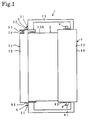
- Fig. 1 is a plan view of an ink ribbon cartridge according to the invention;
- Fig. 2 is a front view of the ink ribbon cartridge shown in Fig. 1;
- Fig. 3 is a bottom view of the ink ribbon cartridge shown in Fig. 1 in an opened position;
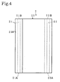
- Fig. 4 is a bottom view of an ink ribbon mounted in the ink ribbon cartridge shown in Fig. 1;
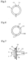
- Fig. 5 is a front view of a spool provided in the ink ribbon cartridge shown in Fig. 1;
- Fig. 6 is a front view of another spool provided in the ink ribbon cartridge shown in Fig. 1;
- Fig. 7 is a front view of a spindle provided in the ink ribbon cartridge shown in Fig. 1;
- Fig. 8 is a side view of the spindle shown in Fig. 7;
- Fig. 9 is a front view of another spindle provided in the ink ribbon cartridge shown in Fig. 1;
- Fig. 10 is a side view of the spindle shown in Fig. 9;
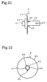
- Fig. 11 is a front view of another spindle provided in the ink ribbon cartridge shown in Fig. 1;
- Fig. 12 is a side view of the spindle shown in Fig. 11; and
- Fig. 13 is a bottom view of a cover in an opened position provided in the ink ribbon cartridge shown in Fig. 1.
-
- Hereinafter preferred embodiments of a recording apparatus according to the invention will be particularly explained with reference to the accompanying drawings.
- First, the ink ribbon cartridge for use in a recording apparatus will be explained. Fig. 1 is a plan view of the ink ribbon cartridge according to the invention; Fig. 2 is a front view of the same; and Fig. 3 is a bottom view thereof. In Fig. 3, the cover is in an opened position.
- The
ink ribbon cartridge 1 is made up of anink ribbon 2, fourspindles 3 to 6, and acover 7. Theink ribbon 2, as shown in Fig. 4, comprises a pair of paper spools 21 and 22, and a band-like sheet 23 wound on thesespools spool 21 and thespool 22 are of the same shape and size and are cylindrical in shape. Thesheet 23 has a ink layer 23A formed on one side of the entire surface of, for instance a resin film. With thesheet 23 inserted between the recording surface of a thermal print head of a thermal printer (e.g., a line printer) and the recording paper, the current is supplied to the heating element of the thermal print head in accordance with the image data, thereby forming image line after image line on the recording paper. At this time, the recording paper is positioned on the ink layer 23A side. On one end face 21A of thespool 21, as shown in Fig. 5,slots slots spool 21. There are also formed slots similar to theslots other end face 21B of thespool 21 and in one end face 22A of thespool 22. In the other end face 22B of thespool 22, as shown in Fig. 6,slots slots spool 22. - The
spindle 3 is unitarily molded of for instance a resin, and, as shown in Figs. 7 and 8, consists of a small-diameter portion 31, a disk-shapedsection 32, agear section 33, a disk-shapedcollar section 34, and aspindle portion 35, which are arranged in the order of mention from one end of the spindle to the other. The disk-shapedsection 32 measures larger in diameter than the small-diameter portion 31 and thespindle portion 35; thegear section 33 is larger in diameter than the disk-shapedsection 32; and thecollar section 34 has a larger diameter than thegear section 33. On the outer peripheral surface of one end of thespindle portion 35 are providedprojections spindle portion 35. Theseprojections slots spool 21 when thespindle portion 35 of thespindle 3 is placed in one end of thespool 21. In the other end of thespindle portion 35 are formedslots spindle 4 is also of the same structure, shape and size as thespindle 3. - The
spindle 5 is unitarily molded of, for instance, a resin and, as shown in Figs. 9 and 10, consists of a small-diameter portion 51, a disk-shapedsection 52, a disk-shaped collar section 53, and spindle portion 54, which are arranged in the order of mention from one end of the spindle to the other. The disk-shapedsection 52 is larger in diameter than the small-diameter portion 51 and the spindle portion 54, and the collar section 53 measures larger in diameter than the disk-shapedsection 52. On the outer peripheral surface of one end portion of the spindle portion 54 are providedprojections 55 and 56, which are arranged 180 degrees apart from each other around the center of the axis of the spindle portion 54. Theseprojections 55 and 56 fit in slots in theother end face 21B of thespool 21 when the spindle portion 54 of thespindle 5 is placed in the other end of thespool 21. In the other end of the spindle portion 54 are formedslots spindle 5 is of the same shape and size as thespindle 3 including the disk-shapedsection 32 and thecollar section 34 but does not include thegear section 33. - The
spindle 6 is unitarily molded of for instance, a resin, and, as shown in Figs. 11 and 12, comprises a small-diameter portion 61, a disk-shapedsection 62, a disk-shapedcollar section 63, and aspindle portion 64, which are arranged in the order of mention from one end of the spindle towards the other. The disk-shapedsection 62 has a larger diameter than the small-diameter portion 61 and thespindle portion 64, and thecollar section 63 has a larger diameter than the disk-shapedsection 62. On the outer peripheral surface of one end of thespindle portion 64 areprojections 65 and 66, which are arranged 150 degrees apart from each other around the center of the axis of thespindle portion 64. Theseprojections 65 and 66 fit in theslots spool 22 when thespindle portion 64 of thespindle 6 is placed in the other end of thespool 22. In the other end of thespool portion 64 are formedslots 67 and 68. Thespindle 6 is a little smaller than the disk-shapedsection 52 of thespindle 5 but is of the same shape and size. However, thespindle 6 includes the projection 56 disposed 30 degrees closer to theprojection 55. - The
cover 7 is unitarily molded of, for example, a resin, and comprises, as shown in Fig. 13, a firstcylindrical section 71, a secondcylindrical section 72, and connectingsections cylindrical section 71 and the secondcylindrical section 72 are connected by the connectingsections cylindrical section 71 consists of anupper half section 75, alower half section 76, and a connectingsection 77. Thelower half section 76 is rotatable on the center of the connectingsection 77. In one end wall of theupper half section 75 and thelower half section 76 are formedsemi-circular recesses recesses lower half section 76 is closed. The round hole formed by therecesses section 32 of thespindle 3 and smaller in diameter than thegear section 33. In the vicinity of one end of theupper half section 75 and thelower half section 76 are formedpartition walls partition walls semi-circular recesses 82 and 83. When thelower half section 76 is closed, a round hole is formed by therecesses 82 and 83. The round hole has a larger diameter than thegear section 33 of thespindle 3 and has a smaller diameter than thecollar section 34. Between the one end wall of theupper half section 75 and thelower half section 76 and thepartition walls ribs 75A and 76A protrude on the inner peripheral surface of theupper half section 75 and thelower half section 76. The projecting ends of theseribs 75A and 76A are flush with the end wall of therecesses 82 and 83 formed in thepartition walls upper half section 75 and thelower half section 76 and thepartition walls gear section 33, and the gear cover section covering thegear section 33 is formed by the one end wall of theupper half section 75 and thelower half section 76, thepartition walls ribs 75A and 76A. - In the other end wall of the
upper half section 75 and thelower half section 76 are formed semi-circular recesses 84 and 85. When thelower half section 76 is in a closed position, a round hole is formed by the recesses 84 and 85. The round hole made by the recesses 84 and 85 is larger in diameter than the disk-shapedsection 52 of thespindle 5 and smaller in diameter than the collar section 53. - The second
cylindrical section 72 consists of anupper half section 86, alower half section 87, and a connectingsection 88. Thelower half section 87 is rotatable from the center of the connectingsection 88. In one end wall of theupper half section 86 and thelower half section 87 are formedsemi-circular recesses lower half section 87 is in a closed position, a round hole is formed by therecesses recesses spindle 4 and a smaller diameter than thegear section 33. In the vicinity of one end of theupper half section 86 and thelower half section 87 are formedsemi-circular recesses partition walls semi-circular recesses lower half section 87 is in a closed position, a round hole is formed by therecesses spindle 4 and smaller than the collar section. Between the one end wall of theupper half section 86 and thelower half section 87 and thepartition walls upper half section 86 and thelower half section 87. The protruding ends of these ribs 86A and 87A are flush with the end walls of therecesses partition walls upper half section 86 and thelower half section 87 is nearly equal to the width of the gear section of thespindle 4. Thus, the gear cover section covering the gear section of thespindle 4 is formed by the one end walls of theupper half section 86 and thelower half section 87, thepartition walls - In the other end walls of the
upper half section 86 and thelower half section 87 are formedsemi-circular recesses 95 and 96. When thelower half section 87 is in a closed position, a round hole is formed by therecesses 95 and 96. The round hole formed by therecesses 95 and 96, measures larger in diameter than the disk-shapedsection 62 of thespindle 6, and is smaller in diameter than each of thecollar section 63, the round hole formed by therecesses recesses - On the other end of the first
cylindrical section 71 is provided a lockingmember 101 for locking and releasing thelower half section 76 with theupper half section 75, as shown in Fig. 2. The lockingmember 101 comprises aprojection 102 that protrudes from the other end face of theupper half section 75 and alocking section 103 that protrudes from the other end face of thelower half section 76. Thelocking section 103 is secured at the lower end to the other end face of thelower half section 76, and bends toward theupper half section 75 to engage theprojection 102. When theprojection 102 fits in the hole formed nearly at center, theprojection 102 engages with thelocking section 103, thus locking thelower half section 76 to theupper half section 75. On one end face of the firstcylindrical section 71 there is also provided a locking member similar to the lockingmember 101. - On the other end of the second
cylindrical section 72 is provided a lockingmember 105 for locking and releasing thelower half section 87 to theupper half section 86 as shown in Fig. 2. The lockingmember 105 consists of aprojection 106 that protrudes from the other end face of theupper half section 86, and a lockingmember 107 that protrudes from the other end face of thelower half section 87. Thelocking section 107 is secured at the lower end to the other end face of thelower half section 87, and bends toward theupper half section 86 to engage theprojection 106. When theprojection 106 fits in the hole formed nearly at center, theprojection 106 is engaged with thelocking section 107, thus locking thelower half section 87 to theupper half section 86. On one end face of the secondcylindrical section 72 there is also provided a locking member similar to the lockingmember 105. - Fig. 3 shows the ink ribbon cartridge properly mounted with the
spools ink ribbon 2 and with thespindles 3 to 6 inserted in the spools when mounted in thecover 7. That is, the axial movement of thespool 21 is restricted by contact between thecollar section 34 of thespindle 3 and thepartition walls upper half section 75 and thelower half section 76 of the firstcylindrical section 71, and also by contact between the collar section 53 of thespindle 5 and the other end walls of theupper half section 75 and thelower half section 76 of the firstcylindrical section 71. The axial movement of thespool 22 is restricted by contact between the collar section of thespindle 4 and thepartition walls upper half section 86 and thelower half section 87 of the secondcylindrical section 72. Thespool 22 and thespindles sheet 23, and thespool 21 and thespindles sheet 23. - To replace a used
ink ribbon 2, thecover 7 is opened as shown in Fig. 3, the usedink ribbon 2 is taken out, thespindles 3 to 6 are removed from thespools ink ribbon 2, and then thespindles 3 to 6 are installed to thespools new ink ribbon 2. That is, thespindle portion 35 of thespindle 3 is placed in one end of thespool 21; the spindle portion 54 of thespindle 5 is placed in the other end of thespool 21; the spindle portion of thespindle 4 is placed in one end of thespool 22; and thespindle portion 64 of thespindle 6 is placed in the other end of thespool 22. At this time, as shown in Fig. 12, theprojections 65 and 66 of thespindle 6 are 150 degrees apart from each other around the axis of thespindle portion 64. Also, as shown in Fig. 6, since theslots spool 22 are arranged 150 degrees apart from each other around the center of the axis of thespool 22, thespindle portion 64 of thespindle 6 can be placed only in the other end of thespool 22. That is, when thespindle portion 64 of thespindle 6 is placed in one end or the other end of thespool 21 or in one end of thespool 22, the projection 65 comes into contact with the end face of thespool 21 or thespool 22 and can not be inserted any further beyond this position. In addition, when thespindle sections 37 and 54 of thespindles 3 to 5 are fitted in the other end of thespool 22, theprojections projections 37 and 56 contact the end face of thespool 22, and thereafter can not be inserted any further beyond this position. Consequently, the inserting position of thespindle 6 will be unequivocally determined. It is possible to identify thespindle 6 from among the fourspindles 3 to 6 according to the angle of theprojections 65 and 66, but this identification can be done more easily by using a different color for thespindle 6 fromother spindles 3 to 5, for example. - Furthermore, when the
ink ribbon 2 is mounted to thecover 7, thespindle 6 will be set on the other end of the secondcylindrical section 72 because the round hole in the other end wall of the secondcylindrical section 72 is smaller than the round hole in either end wall of the firstcylindrical section 71 and the round hole in one end wall of the secondcylindrical section 72 and therefore only the disk-shapedsection 62 of thespindle 6 can be loosely placed in the round hole. That is, when thespindles 3 to 5 are positioned on the other side of the secondcylindrical section 72, the round hole formed by therecesses 95 and 96 of theupper half section 86 and thelower half section 87 of the secondcylindrical section 72 is smaller in diameter than the disk-shapedsection 32 of thespindle 3 and the disk-shapedsection 52 of thespindle 5, thelower half section 87 can not be engaged with theupper half section 86, and thecover 7 can not be closed accordingly. Consequently, with theink ribbon 2 set in thecover 7, the other end of thespool 22 is positioned on the other end side of the secondcylindrical section 72, and theink ribbon 2 can be set in the proper mounting and winding directions, accordingly. - In the meantime, the
spindles 3 to 5 can be placed in both ends of thespool 21 and in one end of thespool 22. If, however, thespindles spool 21, thespool 21 becomes longer by the width of thegear section 33 than the spool of which thespindles lower half section 76 of the firstcylindrical section 71 can not be engaged with theupper half section 75. That is, let us suppose that when the disk-shaped section of thespindle 4 is placed in the recess 84 in the other end wall of theupper half section 75 of the firstcylindrical section 71, thecollar section 34 of thespindle 3 is positioned between one end wall of theupper half section 75 and thepartition wall 80. In this position, the rib 75A is provided on theupper half section 75 and therib 76A is provided on thelower half section 76. Therefore, when thelower half section 76 is engaged with theupper half section 75, the inside diameter of the gear cover section comprising the one end wall of theupper half section 75 of the firstcylindrical section 71, thepartition wall 80, the rib 75A and therib 76A is smaller than the diameter of thecollar section 34 of thespindle 3. Therefore when thecollar section 34 of thespindle 3 is disposed between the one end wall of theupper half section 75 and thepartition wall 80, thecover 7 can not be closed. - In addition, when the
collar section 34 of thespindle 3 is held in contact with thepartition wall 80 of theupper half section 75 of the firstcylindrical section 71, the gear section of thespindle 4 is positioned in the recess 84 in the other end wall of theupper half section 75 of the firstcylindrical section 71. The round hole formed by the recess 84 of theupper half section 75 and the recess 85 of thelower half section 76 is smaller in diameter than the gear section of thespindle 4 and therefore thelower half section 76 of the firstcylindrical section 71 can not be engaged with theupper half section 75, and therefore thecover 7 can not be closed. - Furthermore, when the
spindle 5 is fitted in one end of thespool 21 and then thespindle 3 in the other end of thespool 21, for example, the collar, section 53 of thespindle 5 will be positioned in the gear cover section on one end of the firstcylindrical section 71. Consequently, it becomes impossible to engage thelower half section 76 of the firstcylindrical section 71 with theupper half section 75 and thecover 7 can not be closed. - If the
spindles 3 to 6 are properly set in thespools spools cover 7, thecover 7 can not be closed. It is, therefore, possible to reliably prevent defective setting of theink ribbon 2. Thespindle 3 and thespindle 4, being of the same shape and size, may be mutually changed in position without causing any inconvenience. - While this invention has been described in conjunction with specific embodiments thereof, it is evident that many alternatives, modifications, and variations will be apparent to those skilled in the art. Accordingly, preferred embodiments of the invention as set forth herein are intended to be illustrative, not limiting. Various changes may be made without departing from the scope of the invention as described in the following claims.
Claims (10)
- An ink ribbon cartridge (1), comprising:an ink ribbon (2) including a band-like sheet (23) with a layer of ink (23A) formed on one surface thereof;a pair of spools (21, 22) for holding the ink ribbon (2), each of the pair of spools having two ends, two end faces (21A, 21B; 22A, 22B), and a hole formed in each of the two ends;four spindles (3 - 6) each having one end including a disk-shaped section (32, 52, 62), and an other end, wherein each of the other ends of the four spindles (3 - 6) are placed in the holes formed in the ends of the pair of spools (21, 22);
wherein the other end of a specific one (6) of the four spindles cannot be placed in the holes formed in the ends of three of the four ends of the pair of spools (21, 22);a cover (7) covering the pair of spools (21, 22) and having four round holes in which the disk-shaped section (32, 52, 62) of each of the four spindles (3 - 6) is fitted;
characterized in thatthree of the four round holes formed in the cover (7) are formed such that the disk-shaped section of the specific one (6) of the four spindles (3-6) cannot be fitted. - The ink ribbon cartridge of claim 1, wherein two slots (24, 25; 26, 27) are formed in each end face (21A, 21B; 22A, 22B) of the pair of spools (21, 22) and each of the four spindles have two projections (36, 37, 55, 56, 65, 66) which fit in the two slots.
- The ink ribbon cartridge of claim 2, wherein the two projections (65, 66) provided on the specific one (6) of the four spindles are arranged at a different angle from the other three spindles, with respect to an axial center of the specific spindle (6), and the two slots (26, 27) formed in a specific end face (22B) of one (21, 22) of the pair of spools are arranged at a different angle from the slots (24, 25) formed in the end faces (21A) in the other ends of the pair of spools (21, 22) with respect to a center of the end faces and the two projections (65, 66) provided on the specific one (6) of the four spindles are so formed as to be fitted in the two slots formed in the specific end face of one of the pair of spools.
- The ink ribbon cartridge of one of claims 1 to 3, wherein two (3, 4) of the four spindles each have a gear section (33) formed to rotate the spools (21, 22) on the four spindles.
- The ink ribbon cartridge of one of claims 1 to 4, wherein the gear section (33) is larger in diameter than the disk-shaped section (32) and located on the other end of the spindle.
- The ink ribbon cartridge of claim 4 or 5, wherein the cover (7) can be opened and closed so that the round holes will be formed when the cover (7) is in a closed state.
- The ink ribbon cartridge of one of claims 4 to 6, wherein the cover (7) will not close if two spindles (3, 4) with gear sections (33) are positioned in opposite ends of one of the pair of spools (21, 22).
- The ink ribbon cartridge of one of claims 4 to 7, wherein when the cover is closed, two gear cover sections are formed in which the gear sections (33) formed on two (3, 4) of the four spindles are engaged.
- The ink ribbon cartridge of claim 8, wherein on the four spindles (3-6) is formed a disk-shaped collar section (34, 53, 63) which is larger in diameter than an inside diameter of the gear cover sections and the cover (7) will not close when the disk-shaped collar section (53, 63) of one (5, 6) of the four spindles (3-6) without the gear section is placed in either one of the gear cover sections.
- The ink ribbon cartridge of one of claims 1 to 9, wherein the specific one of the four spindles has a color different than the other three of the four spindles.
Applications Claiming Priority (3)
| Application Number | Priority Date | Filing Date | Title |
|---|---|---|---|
| JP21797 | 1988-02-01 | ||
| JP217/97 | 1997-01-06 | ||
| JP00021797A JP3613917B2 (en) | 1997-01-06 | 1997-01-06 | Ink ribbon cartridge |
Publications (2)
| Publication Number | Publication Date |
|---|---|
| EP0852182A1 EP0852182A1 (en) | 1998-07-08 |
| EP0852182B1 true EP0852182B1 (en) | 1999-11-03 |
Family
ID=11467804
Family Applications (1)
| Application Number | Title | Priority Date | Filing Date |
|---|---|---|---|
| EP97122870A Expired - Lifetime EP0852182B1 (en) | 1997-01-06 | 1997-12-24 | Ink Ribbon cartridge |
Country Status (4)
| Country | Link |
|---|---|
| US (4) | US5913621A (en) |
| EP (1) | EP0852182B1 (en) |
| JP (1) | JP3613917B2 (en) |
| DE (1) | DE69700741T2 (en) |
Cited By (4)
| Publication number | Priority date | Publication date | Assignee | Title |
|---|---|---|---|---|
| USD453179S1 (en) | 2000-07-27 | 2002-01-29 | Iimak | Printer cassette |
| USD458295S1 (en) | 2000-07-27 | 2002-06-04 | Iimak | Printer cassette |
| US6714228B1 (en) | 2001-11-27 | 2004-03-30 | Nu-Kote International, Inc. | Ink ribbon cartridge with C-shaped sideplates |
| US6905268B1 (en) | 2001-11-27 | 2005-06-14 | Nu-Kote International, Inc. | Clutch mechanism with one piece plastic spool |
Families Citing this family (14)
| Publication number | Priority date | Publication date | Assignee | Title |
|---|---|---|---|---|
| EP1000765A3 (en) | 1998-01-06 | 2000-08-02 | Brother Kogyo Kabushiki Kaisha | Ink ribbon cartridge |
| US6991388B2 (en) | 1998-01-06 | 2006-01-31 | Brother Kogyo Kabushiki Kaisha | Ink ribbon cartridge having takeup-side cover with opening positioned beneath protrusion in cover |
| US20020186993A1 (en) * | 1998-01-06 | 2002-12-12 | Brother Kogyo Kabushiki Kaisha | Ink ribbon cartridge |
| JP3067025U (en) * | 1999-08-31 | 2000-03-21 | フジコピアン株式会社 | Versatile ink ribbon core |
| JP2001158161A (en) * | 1999-12-02 | 2001-06-12 | Fujicopian Co Ltd | Ink ribbon taking up member |
| EP1182043B1 (en) | 2000-03-31 | 2004-09-22 | Brother Kogyo Kabushiki Kaisha | Ink sheet cartridge and exchangeable ink-sheet set mounted on the ink sheet cartridge |
| US6422770B1 (en) | 2000-07-18 | 2002-07-23 | Nashua Corporation | Universal inked ribbon assembly for printing apparatus |
| US6666597B1 (en) | 2001-10-31 | 2003-12-23 | International Imaging Materials Inc. | Geared drive hub assembly for a printer cartridge |
| US6659664B1 (en) | 2001-11-27 | 2003-12-09 | Nu-Kote International, Inc. | Ink ribbon cartridge with expandable sideplates |
| US6623193B1 (en) | 2001-11-27 | 2003-09-23 | Nu-Kote International, Inc. | One piece clutch mechanism with drive gear |
| US6997629B2 (en) * | 2002-07-31 | 2006-02-14 | Datacard Corporation | Supply items for printers and the like, and method of loading supply items |
| TWI289111B (en) * | 2005-08-01 | 2007-11-01 | Hi Touch Imaging Tech Co Ltd | Ribbon transportation device capable of fastening ribbon |
| JP4513708B2 (en) * | 2005-09-30 | 2010-07-28 | ソニー株式会社 | Ink ribbon cartridge |
| JP2007230155A (en) * | 2006-03-02 | 2007-09-13 | Sony Corp | Ink ribbon cartridge and printer device |
Family Cites Families (26)
| Publication number | Priority date | Publication date | Assignee | Title |
|---|---|---|---|---|
| US4160605A (en) * | 1977-09-26 | 1979-07-10 | Pitney Bowes Deutschland Gmbh | Ink ribbon box |
| JPH07106657B2 (en) | 1984-05-15 | 1995-11-15 | 株式会社東芝 | Ribbon storage cassette |
| JPS6154969A (en) * | 1984-08-27 | 1986-03-19 | Toshiba Corp | Printer |
| JPS61222772A (en) * | 1985-03-28 | 1986-10-03 | Fuji Xerox Co Ltd | Ink ribbon cartridge |
| JPS62164150A (en) | 1986-01-16 | 1987-07-20 | Hitachi Ltd | Program load system for terminal controller |
| JPH0274378A (en) * | 1988-09-09 | 1990-03-14 | Sony Corp | Ribbon cartridge |
| JPH03169578A (en) * | 1989-11-29 | 1991-07-23 | Fujitsu Ltd | Printer |
| US5110228A (en) | 1989-12-20 | 1992-05-05 | Mitsubishi Kasei Corporation | Cassette with a loosening prevention mechanism |
| JP2550191B2 (en) * | 1989-12-25 | 1996-11-06 | 株式会社日立製作所 | Thermal transfer film cassette and ink film used therefor |
| JPH0471878A (en) | 1990-07-13 | 1992-03-06 | Canon Inc | Ink sheet cartridge and recording apparatus using the same |
| DE69127998T2 (en) | 1990-07-13 | 1998-05-28 | Canon Kk | Ribbon cassette for recording apparatus |
| EP0488291A1 (en) | 1990-11-29 | 1992-06-03 | Canon Kabushiki Kaisha | Ink sheet cartridge and recording apparatus using the ink sheet cartridge |
| JPH05270098A (en) | 1992-03-24 | 1993-10-19 | Oki Electric Ind Co Ltd | Head gap regulating mechanism for printer |
| JPH05270089A (en) * | 1992-03-25 | 1993-10-19 | Tokyo Electric Co Ltd | Thermal printer |
| JP2988602B2 (en) | 1992-03-26 | 1999-12-13 | キヤノン株式会社 | Recording device |
| JPH05278284A (en) | 1992-04-02 | 1993-10-26 | Canon Inc | Ink sheet cartridge and recorder |
| JPH061054A (en) * | 1992-06-19 | 1994-01-11 | Nec Corp | Ink ribbon cassette |
| EP0593821B1 (en) | 1992-10-22 | 1997-01-22 | Agfa-Gevaert N.V. | Dye ribbon package for reloading the reloadable cassette of a thermal printer |
| JPH06155877A (en) | 1992-11-18 | 1994-06-03 | Oki Electric Ind Co Ltd | Structure of multiple ink ribbon cassette |
| JPH0732693A (en) | 1993-07-23 | 1995-02-03 | Canon Inc | Recording device |
| US5378072A (en) * | 1993-09-14 | 1995-01-03 | Fargo Electronics, Inc. | Transfer materials supplier |
| FR2713552B1 (en) | 1993-12-15 | 1996-02-09 | Sagem | Ink ribbon loading shoe for thermal transfer printing printer. |
| JPH07214877A (en) * | 1994-02-04 | 1995-08-15 | Murata Mach Ltd | Cassette for ink ribbon |
| JP3127728B2 (en) | 1994-08-29 | 2001-01-29 | 村田機械株式会社 | Ink ribbon cassette |
| USD383743S (en) | 1995-04-04 | 1997-09-16 | Brother Kogyo Kabushiki Kaisha | Ink ribbon cartridge for facsimile transmitter-receiver |
| JP4320792B2 (en) * | 1997-01-06 | 2009-08-26 | ブラザー工業株式会社 | Recording device |
-
1997
- 1997-01-06 JP JP00021797A patent/JP3613917B2/en not_active Expired - Fee Related
- 1997-12-15 US US08/990,732 patent/US5913621A/en not_active Expired - Lifetime
- 1997-12-24 DE DE69700741T patent/DE69700741T2/en not_active Expired - Lifetime
- 1997-12-24 EP EP97122870A patent/EP0852182B1/en not_active Expired - Lifetime
-
1999
- 1999-04-14 US US09/291,189 patent/US6161972A/en not_active Ceased
-
2002
- 2002-12-19 US US10/323,062 patent/USRE39169E1/en not_active Expired - Lifetime
-
2006
- 2006-01-30 US US11/342,231 patent/USRE41064E1/en not_active Expired - Lifetime
Cited By (4)
| Publication number | Priority date | Publication date | Assignee | Title |
|---|---|---|---|---|
| USD453179S1 (en) | 2000-07-27 | 2002-01-29 | Iimak | Printer cassette |
| USD458295S1 (en) | 2000-07-27 | 2002-06-04 | Iimak | Printer cassette |
| US6714228B1 (en) | 2001-11-27 | 2004-03-30 | Nu-Kote International, Inc. | Ink ribbon cartridge with C-shaped sideplates |
| US6905268B1 (en) | 2001-11-27 | 2005-06-14 | Nu-Kote International, Inc. | Clutch mechanism with one piece plastic spool |
Also Published As
| Publication number | Publication date |
|---|---|
| US5913621A (en) | 1999-06-22 |
| DE69700741T2 (en) | 2000-04-13 |
| JP3613917B2 (en) | 2005-01-26 |
| USRE41064E1 (en) | 2009-12-29 |
| DE69700741D1 (en) | 1999-12-09 |
| JPH10193731A (en) | 1998-07-28 |
| USRE39169E1 (en) | 2006-07-11 |
| EP0852182A1 (en) | 1998-07-08 |
| US6161972A (en) | 2000-12-19 |
Similar Documents
| Publication | Publication Date | Title |
|---|---|---|
| USRE41064E1 (en) | Ink ribbon cartridge having a particular spool and spindle arrangement | |
| EP0661166B1 (en) | Ink ribbon cartridge | |
| CA2085080C (en) | Device for identifying an ink ribbon cartridge used in a printer | |
| EP0358520B1 (en) | Ink ribbon cartridges for printing apparatus | |
| US6195111B1 (en) | Cassette casing for thermal transfer printing dye ribbon | |
| US5897256A (en) | Ink ribbon cartridge retention device for a recording apparatus | |
| EP0638434B1 (en) | Ink ribbon cartridge | |
| EP1827851A1 (en) | Spool adapter | |
| KR20160127776A (en) | Tape cartridge | |
| KR20010075328A (en) | A sensor hub for a print ribbon supply roll and method | |
| US5433540A (en) | Combined spool retainer and installation device | |
| GB2266276A (en) | Facilitating reloading of ink-sheet cassettes for printers. | |
| JP2001232880A (en) | Ribbon cassette | |
| JP4595092B2 (en) | Ink ribbon spool | |
| US6543945B2 (en) | Ink film with cores having different diameter shaft sections | |
| CN116728982A (en) | Tape cartridge, tape spool, and tape cartridge set | |
| JPH0516480A (en) | Ink film cassette | |
| JP3580807B2 (en) | Ink sheet set | |
| KR0115945Y1 (en) | Device for supporting donor spool for a recorder | |
| JPH07266670A (en) | Ink ribbon cartridge | |
| JPH0516479A (en) | Ink film cassette | |
| US20070274760A1 (en) | Cartridge case | |
| JP2004082740A (en) | Ink sheet set | |
| JPH09220838A (en) | Ink ribbon cassette for printer | |
| KR19990056914A (en) | Cartridges with thermal ribbon release |
Legal Events
| Date | Code | Title | Description |
|---|---|---|---|
| PUAI | Public reference made under article 153(3) epc to a published international application that has entered the european phase |
Free format text: ORIGINAL CODE: 0009012 |
|
| AK | Designated contracting states |
Kind code of ref document: A1 Designated state(s): CH DE FR GB LI NL |
|
| AX | Request for extension of the european patent |
Free format text: AL;LT;LV;MK;RO;SI |
|
| 17P | Request for examination filed |
Effective date: 19980819 |
|
| 17Q | First examination report despatched |
Effective date: 19981019 |
|
| AKX | Designation fees paid |
Free format text: CH DE FR GB LI NL |
|
| RBV | Designated contracting states (corrected) |
Designated state(s): CH DE FR GB LI NL |
|
| GRAG | Despatch of communication of intention to grant |
Free format text: ORIGINAL CODE: EPIDOS AGRA |
|
| GRAG | Despatch of communication of intention to grant |
Free format text: ORIGINAL CODE: EPIDOS AGRA |
|
| GRAH | Despatch of communication of intention to grant a patent |
Free format text: ORIGINAL CODE: EPIDOS IGRA |
|
| GRAH | Despatch of communication of intention to grant a patent |
Free format text: ORIGINAL CODE: EPIDOS IGRA |
|
| GRAA | (expected) grant |
Free format text: ORIGINAL CODE: 0009210 |
|
| AK | Designated contracting states |
Kind code of ref document: B1 Designated state(s): CH DE FR GB LI NL |
|
| REG | Reference to a national code |
Ref country code: CH Ref legal event code: NV Representative=s name: R. A. EGLI & CO. PATENTANWAELTE Ref country code: CH Ref legal event code: EP |
|
| REF | Corresponds to: |
Ref document number: 69700741 Country of ref document: DE Date of ref document: 19991209 |
|
| ET | Fr: translation filed | ||
| PLBE | No opposition filed within time limit |
Free format text: ORIGINAL CODE: 0009261 |
|
| STAA | Information on the status of an ep patent application or granted ep patent |
Free format text: STATUS: NO OPPOSITION FILED WITHIN TIME LIMIT |
|
| 26N | No opposition filed | ||
| REG | Reference to a national code |
Ref country code: GB Ref legal event code: IF02 |
|
| REG | Reference to a national code |
Ref country code: FR Ref legal event code: PLFP Year of fee payment: 19 |
|
| PGFP | Annual fee paid to national office [announced via postgrant information from national office to epo] |
Ref country code: CH Payment date: 20151026 Year of fee payment: 19 Ref country code: GB Payment date: 20151125 Year of fee payment: 19 |
|
| PGFP | Annual fee paid to national office [announced via postgrant information from national office to epo] |
Ref country code: FR Payment date: 20151124 Year of fee payment: 19 Ref country code: NL Payment date: 20151207 Year of fee payment: 19 |
|
| PGFP | Annual fee paid to national office [announced via postgrant information from national office to epo] |
Ref country code: DE Payment date: 20151230 Year of fee payment: 19 |
|
| REG | Reference to a national code |
Ref country code: DE Ref legal event code: R119 Ref document number: 69700741 Country of ref document: DE |
|
| REG | Reference to a national code |
Ref country code: CH Ref legal event code: PL |
|
| REG | Reference to a national code |
Ref country code: NL Ref legal event code: MM Effective date: 20170101 |
|
| GBPC | Gb: european patent ceased through non-payment of renewal fee |
Effective date: 20161224 |
|
| PG25 | Lapsed in a contracting state [announced via postgrant information from national office to epo] |
Ref country code: NL Free format text: LAPSE BECAUSE OF NON-PAYMENT OF DUE FEES Effective date: 20170101 |
|
| REG | Reference to a national code |
Ref country code: FR Ref legal event code: ST Effective date: 20170831 |
|
| PG25 | Lapsed in a contracting state [announced via postgrant information from national office to epo] |
Ref country code: FR Free format text: LAPSE BECAUSE OF NON-PAYMENT OF DUE FEES Effective date: 20170102 Ref country code: CH Free format text: LAPSE BECAUSE OF NON-PAYMENT OF DUE FEES Effective date: 20161231 Ref country code: LI Free format text: LAPSE BECAUSE OF NON-PAYMENT OF DUE FEES Effective date: 20161231 |
|
| PG25 | Lapsed in a contracting state [announced via postgrant information from national office to epo] |
Ref country code: GB Free format text: LAPSE BECAUSE OF NON-PAYMENT OF DUE FEES Effective date: 20161224 Ref country code: DE Free format text: LAPSE BECAUSE OF NON-PAYMENT OF DUE FEES Effective date: 20170701 |