EP0849879A2 - Recursive filters for polyphase structures - Google Patents
Recursive filters for polyphase structures Download PDFInfo
- Publication number
- EP0849879A2 EP0849879A2 EP19970309716 EP97309716A EP0849879A2 EP 0849879 A2 EP0849879 A2 EP 0849879A2 EP 19970309716 EP19970309716 EP 19970309716 EP 97309716 A EP97309716 A EP 97309716A EP 0849879 A2 EP0849879 A2 EP 0849879A2
- Authority
- EP
- European Patent Office
- Prior art keywords
- streams
- filter
- recursive
- parallel
- fir
- Prior art date
- Legal status (The legal status is an assumption and is not a legal conclusion. Google has not performed a legal analysis and makes no representation as to the accuracy of the status listed.)
- Withdrawn
Links
Images


Classifications
-
- H—ELECTRICITY
- H03—ELECTRONIC CIRCUITRY
- H03H—IMPEDANCE NETWORKS, e.g. RESONANT CIRCUITS; RESONATORS
- H03H17/00—Networks using digital techniques
- H03H17/02—Frequency selective networks
- H03H17/0248—Filters characterised by a particular frequency response or filtering method
- H03H17/0264—Filter sets with mutual related characteristics
- H03H17/0273—Polyphase filters
- H03H17/0277—Polyphase filters comprising recursive filters
Definitions
- the present invention relates to communications systems, and, in particular, to receivers and transmitters having polyphase structure.
- multiple signal channels are processed within a transmitter for transmission as a single signal stream to a receiver which is then able to process the received signal stream to recover the individual signal channels.
- Examples of such communications schemes are analog AMPS (American Mobile Phone System) and the time division multiple access (TDMA) industry standard (IS)-54 scheme.
- TDMA time division multiple access
- IS industry standard
- block processing techniques is that there will typically not be significant additional costs incurred as extra signal channels are added to the system.
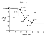
- Fig. 1 there is shown a representation of an example of the filter specification requirements for AMPS and TDMA (IS-54). According to those specification, all candidate transfer functions should lie outside regions identified as 102 and 104 in Fig. 1.
- One aspect of the present invention is to provide channelizing transmitters and receivers that satisfy the requirements for communications schemes such as AMPS and TDMA (IS-54). Structures in accordance with the present invention may be implemented with fewer coefficients -- and are therefore less complex and less expensive -- than conventional designs.
- the present invention is a polyphase receiver, comprising (a) a serial-to-parallel converter adapted to convert a serial stream of signals corresponding to M signal channels into M parallel streams; (b) M FIR filters, each of which is adapted to filter one of the M parallel streams; (c) a Fourier transform adapted to transform the M FIR-filtered streams to generate M transformed streams; and (d) one or more recursive filters, each of which is adapted to filter one of the transformed streams to recover one of the M signal channels.
- the present invention is a method for processing communications signals, comprising the steps of (a) receiving a serial stream of signals corresponding to M signal channels; (b) converting the serial stream into M parallel streams; and (c) applying a filter to the M parallel streams to recover the M signal channels, wherein the filter implements a function comprising a non-recursive numerator and a recursive denominator that is a polynomial in z M .
- the present invention is a polyphase transmitter, comprising (a) L recursive filters, each of which is adapted to recursively filter one of M parallel streams corresponding to M signal channels, wherein L is between one and M inclusive; (b) a Fourier transform adapted to transform the L recursively filtered streams and the (M-L) other parallel streams to generate M transformed streams; (c) M FIR filters, each of which is adapted to filter one of the M transformed streams; and (d) a parallel-to-serial converter adapted to convert the M FIR-filtered streams into a serial stream of signals corresponding to the M signal channels for transmission.
- the present invention is a method for processing communications signals, comprising the steps of (a) receiving M parallel streams corresponding to M signal channels; (b) applying a filter to the M parallel streams to generate M parallel filtered streams, wherein the filter implements a function comprising a non-recursive numerator and a recursive denominator that is a polynomial in z M ; and(c) converting the M parallel filtered streams into a serial stream of signals corresponding to the M signal channels for transmission.
- the present invention is directed to channelizing transmitters and receivers that implement recursive polyphase filters.
- the inventor has found that such structures can be implemented using fewer coefficients than conventional designs.
- channelizing transmitters and receivers in accordance with the present invention can be simpler and less expensive than conventional systems.
- Transmitter 200 comprises one or more recursive filters 202 , M -point forward discrete Fourier transform (FDFT) 204 , M finite impulse response (FIR) filters 206 , and parallel-to-serial (P/S) converter 208 , which comprises a cascade of delays 210 .
- Transform 204 may be a fast Fourier transform (FFT).
- Each recursive filter 202 has the form 1 / D ( z M )
- each FIR filter 206 has the form N i ( z )
- each delay 210 has the form z -1 .
- Transmitter 200 converts M signal channels into a single combined serial stream that can be further processed (e.g., modulated) for transmission to one or more remote receivers.
- the signals corresponding to one or more (and possibly all) of the input channels are recursively filtered by one of the recursive filter 202 (e.g., channels 0 and i in Fig. 2). Meanwhile, the signals corresponding to the other input channels (e.g., channels j and M -1) are not recursively filtered.
- the signals corresponding to all M input channels are transformed by FDFT 204 .
- Each of the resulting M transformed streams is then filtered by one of the FIR filters 206 .
- P/S converter 208 converts the resulting M parallel FIR-filtered streams into a single serial stream that can be further processed for transmission.
- Receiver 300 comprises serial-to-parallel (S/P) converter 302 (which comprises a cascade of delays 304 ), M FIR filters 306 , M -point inverse discrete Fourier transform (IDFT) 308 , and one or more recursive filters 310 .
- Transform 308 may be an FFT.
- Each delay 304 has the form z -1
- each FIR filter 306 has the form N i ( z )
- each recursive filter 310 has the form 1 / D j ( z M ) .
- Receiver 300 receives a serial signal stream corresponding to the serial stream generated by transmitter 200 of Fig. 2 and processes that received serial stream to recover M channel signals corresponding to the original M channel signals processed by transmitter 200 .
- S/P converter 302 converts the received serial stream into M parallel streams that are then FIR filtered by one of the FIR filters 306 .
- the resulting M FIR-filtered streams are then transformed by IDFT 308 .
- One or more (and possibly all) of the resulting transformed streams are then recursively filtered by one of the recursive filters 310 to recover one or more of the signal channels (e.g., channels 0 and i in Fig. 3). Meanwhile, the other resulting transformed streams do not need to be recursively filtered to recover the rest of the signal channels (e.g., channels j and M- 1 in Fig. 3).
- the corresponding signals are also recursively filtered at the receiver; otherwise, the corresponding signals are not recursively filtered at the receiver.
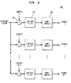
- Converters 402 isolate each of M signal channels from a wideband digital stream x(n) by digitally downconverting the particular channel to baseband. For each channel, lowpass filter 404 then removes unwanted signals, which lie outside the required channel bandwidth. Since the samples will typically have a considerable degree of redundancy, downsampler 406 downsamples the baseband signal to produce one of M narrowband channel signals c i ( m ). Each carrier has the form each lowpass filter 404 has the form h(n), and each downsampler 406 downsamples by a factor of M, the number of channels.
- Fig. 4 an equivalent form of the structure of Fig. 4 is the polyphase filter. See, e.g., R.E. Crochiere and L.R. Rabiner, Multirate Digital Signaling Processing , Prentice-Hall, 1983, the teachings of which are incorporated here by reference.
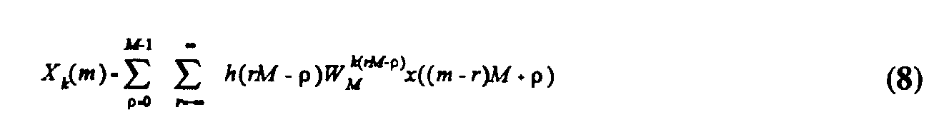
- Equation (6) The k -th channel output is obtained from Equation (6) as follows:
- Equation (7) The change of variable (mM-n) ⁇ n in Equation (6) re-arranges this to Equation (7) as follows:
- Equation (9) Equation (9) as follows: where * denotes discrete convolution.
- Receiver 500 comprises S/P converter 502 (which comprises a cascade of delays 504 ), M sub-filters 506 , and M-point IDFT 508 .
- Each delay 504 has the form z -1 and each sub-filter 506 has the form H i (z -M ) .
- Receiver 500 processes a received serial signal stream to recover M channel signals.
- the prototype filter H(z) is formed from Equation (11) as follows:
- FIR structures are used to implement the prototype and resulting sub-filters, but it is clear that, in order to meet the demanding specifications of air-interface standards such as AMPS and TDMA (IS-54), an extremely high quality (Q) prototype filter is required.
- IIR decimation structure An infinite impulse response (IIR) decimation structure is described in M.G. Bellanger, J.L. Daguet, and G.P. Lepagnol, "Interpolation, extrapolation, and reduction of computation speed in digital filters," IEEE Transactions on Acoustics, Speech and Signal Processing, Vol. ASSP-22, pp. 231-235, August 1974 ("the Bellanger reference”), which is incorporation herein by reference.
- This structure may be generalized to obtain the polyphase form of receiver 300 of Fig. 3. With the FIR polyphase filter of Fig. 5, there was no restriction placed on the form of the prototype filter. Unfortunately, this is no longer the case with IIR prototype filters.
- the denominator is a polynomial in z M . This allows the denominator to be placed at the output of the polyphase channelizer and be operated at the maximally decimated rate (see, e.g., recursive filters 310 of Fig. 3).
- Equation (12) can be rewritten in terms of a numerator N(z) over a denominator D(z) , as shown in Equation (13) as follows:
- An extremely low-order elliptic filter may be used to meet the AMPS and TDMA (IS -54) specification of Fig. 1.
- Elliptic filters can be realized in a direct form infinite impulse cascade of S second-order sections, as described by Equation (14) as follows:
- 1 z - p i z M -1 + p i z M -2 + ... + p M -1 i z M - p M i
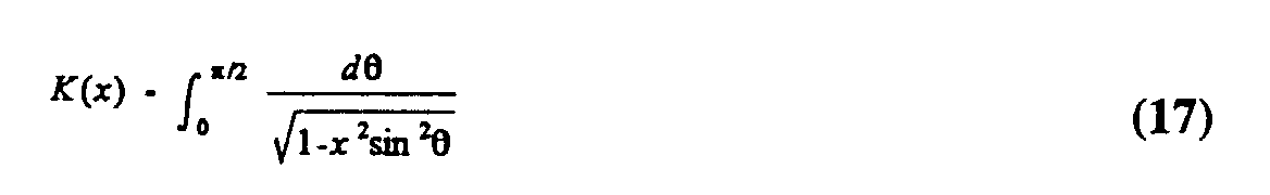
- Equation (16) K k K ( 1- k 2 1 ) K ( k 1 ) K ( 1- k 2 )
- n ell 7.22.
- Allpass filters provide a computationally efficient means for realizing high-order IIR filter structures. See, e.g., F.J. Harris, "On the Design and Performance of Efficient and Novel Filter Structures using Recursive Allpass Filters," International Symposium on Signal Processing and its Applications, (Gold Coast, Australia), pp. 1-6, August 1992 (“the Harris reference”), the teachings of which are incorporated herein by reference.
- the basic transfer function of an allpass filter, with K stages, is given by Equation (20) as follows: By creating two or more such structures and combining their outputs, filtering is achieved by arranged their phase characteristics to be constructive in the passband and destructive in the stopband.
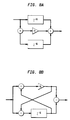
- FIGs. 8(a) and (b) there are shown representations of how an allpass structure can be implemented using a single multiply operation per input sample.
- the structure shown in Fig. 8(a) has two additions and two memory elements, while the structure shown in Fig. 8(b) has three additions and a single memory element.
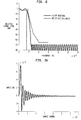
- Fig. 10 there is shown a graphical representation of an example equiripple filter design. This filter meets and, in fact, exceeds the specification required for a two-channel system with a single pair of allpass filters.
- This filter can be viewed as having two filters: one that is purely non-recursive (e.g., FIR) and one that is purely recursive (e.g., IIR). If we substitute z ⁇ z M/2 , where M is the number of polyphase channels in the system, then a filter is obtained that has the correct transition bandwidth and attenuation for the specification, but has alias filters throughout the band.
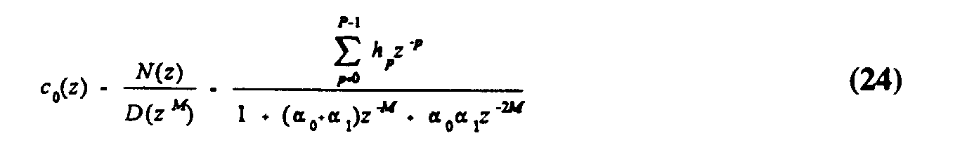
- Equation (23) shows that this filter already has the correct form for the IIR polyphase transformation of receiver 300 of Fig. 3. This indicates the appropriate way to proceed with the design of an M -channel filter.
- Equation (24) Equation (24) as follows: where P is the total number of coefficients required to implement the non-recursive part of the polyphase receiver. This may be realized with a single recursive quadratic filter at the decimated rate for each channel. The channel selectivity is obtained from the non-recursive part of the filter, N(z) (e.g., FIR filters 306 of Fig. 3).
- the filter coefficients of N(z) can be computed using a modified Remez exchange algorithm. See, e.g., J.H. McClellan, T.W. Parks, and L.R. Rabiner, "A Computer Program for Designing Optimum FIR Linear Phase Digital Filters," IEEE Trans. on Audio and Electroacoustics, Vol. AU-21, pp. 506-526, December 1973. Modifications to the Remez exchange algorithm adjust the desired passband response according to D(z M ) and weight proportionally the error in the stopband according to the reciprocal of D(z M ).
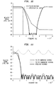
- Fig. 11 shows a graphical representation of the performance of a 256-channel filter generated using this approach.
- Fig. 11 shows the recursive (i.e., denominator) response as a dotted line, the non-recursive (i.e., numerator) response as a dashed line, and the resultant response as a solid line.
- Fig. 12 there is shown a graphical representation of the performance of the 256-channel filter of Fig. 11 (shown in solid line) as compared to the IS-54 specification requirements (shown in dashed line).
- the number of coefficients required to meet the IS-54 specification is 3.5 M (for M even and greater than 2).
- M for M even and greater than 2.
- a total of 896 coefficients are required, as compared with the pure FIR case which requires 1929 coefficients.
- This provides a significant saving in computation and also in performance, since the recursive filter of the present invention has much better passband and stopband performance as compared to the performance of the FIR filter shown in Fig. 6.
- the phase characteristics of the filter of Fig. 12 are also fairly linear, primarily because the dominant portion of this filter is a linear phase filter.
Abstract
Description


| Coefficients for 8th-Order Elliptic Filter | |||
| Section | b[s,1] | a[s,1] | a[s,2] |
| 0 | -1.9997893273588231988 | -1.9986189304509249798 | 0.99862006832468652728 |
| 1 | -1.9999693832408007577 | -1.9991017162108251082 | 0.99910633603931675584 |
| 2 | -1.9999831564812771134 | -1.9995756543488480972 | 0.99958351265916256523 |
| 3 | -1.9999861614273464205 | -1.9998762557622113967 | 0.99988564620734843302 |


Claims (11)
- A method for processing communications signals, comprising the steps of:(a) receiving a serial stream of signals corresponding to M signal channels;(b) converting the serial stream into M parallel streams; and(c) applying a filter to the M parallel streams to recover the M signal channels, wherein the filter implements a function comprising a non-recursive numerator and a recursive denominator that is a polynomial in zM.
- The invention of claim 1, wherein step (c) comprises the steps of:(1) applying a finite impulse response (FIR) filter to each parallel stream;(2) applying a Fourier transform to the M FIR-filtered streams to generate M transformed streams; and(3) applying a recursive filter to at least one of the M transformed streams.
- A polyphase receiver, comprising:(a) a serial-to-parallel converter adapted to convert a serial stream of signals corresponding to M signal channels into M parallel streams;(b) M FIR filters, each of which is adapted to filter one of the M parallel streams;(c) a Fourier transform adapted to transform the M FIR-filtered streams to generate M transformed streams; and(d) one or more recursive filters, each of which is adapted to filter one of the transformed streams to recover one of the M signal channels.
- A method for processing communications signals, comprising the steps of:(a) receiving M parallel streams corresponding to M signal channels;(b) applying a filter to the M parallel streams to generate M parallel filtered streams, wherein the filter implements a function comprising a non-recursive numerator and a recursive denominator that is a polynomial in zM; and(c) converting the M parallel filtered streams into a serial stream of signals corresponding to the M signal channels for transmission.
- The invention of claim 4, wherein step (b) comprises the steps of:(1) applying a recursive filter to L of the M parallel streams, wherein L is between one and M inclusive;(2) applying a Fourier transform to the L recursively filtered streams and the M-L other parallel streams to generate M transformed streams; and(3) applying a FIR filter to each of the M transformed streams.
- The invention of claim 2 or 4, wherein the Fourier transform is an FFT or a DFT.
- The invention of claim 1, 4 or 6, wherein the recursive denominator is a polynomial in zM of order of at least two.
- A polyphase transmitter, comprising:(a) L recursive filters, each of which is adapted to recursively filter one of M parallel streams corresponding to M signal channels, wherein L is between one and M inclusive;(b) a Fourier transform adapted to transform the L recursively filtered streams and the (M-L other parallel streams to generate M transformed streams;(c) M FIR filters, each of which is adapted to filter one of the M transformed streams; and(d) a parallel-to-serial converter adapted to convert the M FIR-filtered streams into a serial stream of signals corresponding to the M signal channels for transmission.
- The invention of claim 3 or 8, wherein each recursive filter implements a function comprising a denominator that is a polynomial in zM.
- The invention of claim 9, wherein the denominator is a polynomial in zM of order of at least two.
- The invention of claim 3,8 or 10, wherein the Fourier transform is an FFT or a DFT.
Applications Claiming Priority (2)
| Application Number | Priority Date | Filing Date | Title |
|---|---|---|---|
| US08/769,980 US5926455A (en) | 1996-12-19 | 1996-12-19 | Recursive filters for polyphase structures |
| US769980 | 1996-12-19 |
Publications (2)
| Publication Number | Publication Date |
|---|---|
| EP0849879A2 true EP0849879A2 (en) | 1998-06-24 |
| EP0849879A3 EP0849879A3 (en) | 2001-05-16 |
Family
ID=25087103
Family Applications (1)
| Application Number | Title | Priority Date | Filing Date |
|---|---|---|---|
| EP19970309716 Withdrawn EP0849879A3 (en) | 1996-12-19 | 1997-12-02 | Recursive filters for polyphase structures |
Country Status (4)
| Country | Link |
|---|---|
| US (1) | US5926455A (en) |
| EP (1) | EP0849879A3 (en) |
| JP (1) | JP3325819B2 (en) |
| CA (1) | CA2221217C (en) |
Families Citing this family (26)
| Publication number | Priority date | Publication date | Assignee | Title |
|---|---|---|---|---|
| JP3848421B2 (en) * | 1997-01-31 | 2006-11-22 | 秀男 村上 | Multiplexing apparatus and multiplexing system for discrete-time signal, and multiplexing method for discrete-time signal |
| JP4326031B2 (en) * | 1997-02-06 | 2009-09-02 | ソニー株式会社 | Band synthesis filter bank, filtering method, and decoding apparatus |
| FR2761550B1 (en) * | 1997-03-28 | 1999-06-25 | France Telecom | DIGITAL FILTER FOR FRACTIONAL DELAYS |
| JP2001104281A (en) * | 1999-10-13 | 2001-04-17 | Ge Yokogawa Medical Systems Ltd | Direct digital synthesizer and mri equipment |
| AU2757701A (en) * | 1999-12-30 | 2001-07-16 | Bandspeed, Inc. | Approach for processing data received from a communications channel in finite precision arithmetic applications |
| EP1158674B1 (en) * | 2000-05-24 | 2008-06-18 | Sony Deutschland GmbH | A digital filter for IQ-Generation, noise shaping and neighbour channel suppression |
| US6731690B2 (en) * | 2000-12-01 | 2004-05-04 | Motorola, Inc. | Methods and apparatus for transmultiplexing a multi-channel signal |
| US7290021B2 (en) * | 2001-04-24 | 2007-10-30 | California Institute Of Technology | Method and apparatus for parallel signal processing |
| US7164741B2 (en) * | 2001-05-09 | 2007-01-16 | Signum Concept, Inc. | Non-recursive resampling digital fir filter structure for demodulating 3G cellular signals |
| US7158591B2 (en) * | 2001-05-09 | 2007-01-02 | Signum Concept, Inc. | Recursive resampling digital filter structure for demodulating 3G wireless signals |
| US7388930B1 (en) | 2001-08-10 | 2008-06-17 | Bandspeed, Inc. | Method and apparatus for removing crosstalk and other interference in communications systems |
| US20030069009A1 (en) * | 2001-10-04 | 2003-04-10 | Harnden Robert R. | Cellular communications channelizer |
| US6792057B2 (en) * | 2002-08-29 | 2004-09-14 | Bae Systems Information And Electronic Systems Integration Inc | Partial band reconstruction of frequency channelized filters |
| EP1404017A1 (en) * | 2002-09-27 | 2004-03-31 | Harman/Becker Automotive Systems GmbH | Parametric recursive digital filter |
| DE10256452A1 (en) * | 2002-12-03 | 2004-06-24 | Rohde & Schwarz Gmbh & Co. Kg | Method for analyzing the channel impulse response of a transmission channel |
| US8589461B1 (en) * | 2003-03-24 | 2013-11-19 | Altera Corporation | Dynamically re-configurable signal decimation system using a finite impulse response (FIR) filter |
| US8725785B1 (en) | 2004-08-09 | 2014-05-13 | L-3 Communications Corp. | Parallel infinite impulse response filter |
| US7027942B1 (en) | 2004-10-26 | 2006-04-11 | The Mitre Corporation | Multirate spectral analyzer with adjustable time-frequency resolution |
| DE102005046445B4 (en) * | 2005-09-28 | 2019-10-10 | Snaptrack, Inc. | Bandpass filter |
| WO2007105980A1 (en) * | 2006-03-16 | 2007-09-20 | Intel Corporation | Method for channel estimation using recursive filtering and multicarrier receiver with interference-aware demodulation |
| US9059786B2 (en) * | 2011-07-07 | 2015-06-16 | Vecima Networks Inc. | Ingress suppression for communication systems |
| US8693601B2 (en) * | 2012-01-03 | 2014-04-08 | Intel Corporation | Self-correcting multirate filter |
| EP2744102B1 (en) * | 2012-12-17 | 2018-07-04 | Nxp B.V. | Digital down converter circuit |
| US10211856B1 (en) * | 2017-10-12 | 2019-02-19 | The Boeing Company | Hardware scalable channelizer utilizing a neuromorphic approach |
| EP3771100A1 (en) * | 2019-07-23 | 2021-01-27 | Comet AG | Device and method for filtering multiple pulse signals |
| WO2023127225A1 (en) * | 2021-12-28 | 2023-07-06 | アルプスアルパイン株式会社 | Filter designing method, and iir type all-pass filter |
Citations (3)
| Publication number | Priority date | Publication date | Assignee | Title |
|---|---|---|---|---|
| US4107470A (en) * | 1976-02-24 | 1978-08-15 | Nippon Electric Co., Ltd. | Digital SSB-FDM communication system derived from a complex band-pass digital filter bank and by a filter breakdown process |
| US4623980A (en) * | 1981-05-09 | 1986-11-18 | Te Ka De Felten & Guilleaume Fernmeldeanlagen Gmbh | Method of processing electrical signals by means of Fourier transformations |
| US4918524A (en) * | 1989-03-14 | 1990-04-17 | Bell Communications Research, Inc. | HDTV Sub-band coding using IIR filter bank |
Family Cites Families (2)
| Publication number | Priority date | Publication date | Assignee | Title |
|---|---|---|---|---|
| US4785447A (en) * | 1987-02-17 | 1988-11-15 | Nec Corporation | FDM demultiplexer using oversampled digital filters |
| US5757867A (en) * | 1995-03-30 | 1998-05-26 | The United States Of America As Represented By The Secretary Of The Navy | Digital mixing to baseband decimation filter |
-
1996
- 1996-12-19 US US08/769,980 patent/US5926455A/en not_active Expired - Lifetime
-
1997
- 1997-11-17 CA CA 2221217 patent/CA2221217C/en not_active Expired - Fee Related
- 1997-12-02 EP EP19970309716 patent/EP0849879A3/en not_active Withdrawn
- 1997-12-04 JP JP33453697A patent/JP3325819B2/en not_active Expired - Fee Related
Patent Citations (3)
| Publication number | Priority date | Publication date | Assignee | Title |
|---|---|---|---|---|
| US4107470A (en) * | 1976-02-24 | 1978-08-15 | Nippon Electric Co., Ltd. | Digital SSB-FDM communication system derived from a complex band-pass digital filter bank and by a filter breakdown process |
| US4623980A (en) * | 1981-05-09 | 1986-11-18 | Te Ka De Felten & Guilleaume Fernmeldeanlagen Gmbh | Method of processing electrical signals by means of Fourier transformations |
| US4918524A (en) * | 1989-03-14 | 1990-04-17 | Bell Communications Research, Inc. | HDTV Sub-band coding using IIR filter bank |
Also Published As
| Publication number | Publication date |
|---|---|
| JPH10190604A (en) | 1998-07-21 |
| EP0849879A3 (en) | 2001-05-16 |
| CA2221217A1 (en) | 1998-06-19 |
| JP3325819B2 (en) | 2002-09-17 |
| CA2221217C (en) | 2001-10-30 |
| US5926455A (en) | 1999-07-20 |
Similar Documents
| Publication | Publication Date | Title |
|---|---|---|
| EP0849879A2 (en) | Recursive filters for polyphase structures | |
| EP1540941B1 (en) | Partial band reconstruction of frequency channelized filters | |
| CA2315940C (en) | Decimation filtering apparatus and method | |
| Phoong et al. | A new class of two-channel biorthogonal filter banks and wavelet bases | |
| Lin et al. | A new flexible filter bank for low complexity spectrum sensing in cognitive radios | |
| US7035888B2 (en) | Digital sampling rate converter for compensation for drop of in-band signal | |
| US7158591B2 (en) | Recursive resampling digital filter structure for demodulating 3G wireless signals | |
| WO2002080362A1 (en) | Aliasing reduction using complex-exponential modulated filterbanks | |
| Wada | Design of nonuniform division multirate FIR filter banks | |
| JP4235557B2 (en) | Multirate digital transceiver | |
| Kiya et al. | A linear phase two-channel filter bank allowing perfect reconstruction | |
| Babic et al. | Decimation by irrational factor using CIC filter and linear interpolation | |
| KR20090040298A (en) | Method for processing a digital input signal in a digital domain and digital filter circuit for processing a digital input signal | |
| US10755721B1 (en) | Multichannel, multirate, lattice wave filter systems and methods | |
| Hareesh et al. | Analysis of different rational decimated filter banks derived from the same set of prototype filters | |
| Navarro et al. | Practical Non-Uniform Channelization for Multistandard Base Stations | |
| Zivaljevic et al. | Design of recursive digital filters for subband coding | |
| Vaidya et al. | Low Complexity Non Maximally Coefficient Symmetry Multi Rate Filter Bank for Wideband Channelization | |
| Cadena et al. | Interpolated FIR based practically perfect reconstruction filter bank | |
| Hart et al. | Polyphase allpass IIR structures for sub-band acoustic echo cancellation. | |
| Yeshwantrao | Design and Implementation of Some Digital Signal Processing Blocks | |
| Rao et al. | Multirate Filter Banks | |
| Devi et al. | Multistage Multirate Filtering Technique for Channelization | |
| Palomo Navarro et al. | Practical Non-Uniform Channelization for Multistandard Base Stations | |
| Ikehara et al. | Uniform filter bank containing N‐path digital filter |
Legal Events
| Date | Code | Title | Description |
|---|---|---|---|
| PUAI | Public reference made under article 153(3) epc to a published international application that has entered the european phase |
Free format text: ORIGINAL CODE: 0009012 |
|
| AK | Designated contracting states |
Kind code of ref document: A2 Designated state(s): DE GB |
|
| AX | Request for extension of the european patent |
Free format text: AL;LT;LV;MK;RO;SI |
|
| 17P | Request for examination filed |
Effective date: 20000817 |
|
| PUAL | Search report despatched |
Free format text: ORIGINAL CODE: 0009013 |
|
| AK | Designated contracting states |
Kind code of ref document: A3 Designated state(s): AT BE CH DE DK ES FI FR GB GR IE IT LI LU MC NL PT SE |
|
| AX | Request for extension of the european patent |
Free format text: AL;LT;LV;MK;RO;SI |
|
| AKX | Designation fees paid |
Free format text: DE GB |
|
| 17Q | First examination report despatched |
Effective date: 20050330 |
|
| STAA | Information on the status of an ep patent application or granted ep patent |
Free format text: STATUS: THE APPLICATION IS DEEMED TO BE WITHDRAWN |
|
| 18D | Application deemed to be withdrawn |
Effective date: 20060902 |