EP0848931A2 - Externally moveable intracavity probe for MRI imaging and spectroscopy - Google Patents
Externally moveable intracavity probe for MRI imaging and spectroscopy Download PDFInfo
- Publication number
- EP0848931A2 EP0848931A2 EP98104302A EP98104302A EP0848931A2 EP 0848931 A2 EP0848931 A2 EP 0848931A2 EP 98104302 A EP98104302 A EP 98104302A EP 98104302 A EP98104302 A EP 98104302A EP 0848931 A2 EP0848931 A2 EP 0848931A2
- Authority
- EP
- European Patent Office
- Prior art keywords
- coil
- shaft
- interest
- probe
- balloon structure
- Prior art date
- Legal status (The legal status is an assumption and is not a legal conclusion. Google has not performed a legal analysis and makes no representation as to the accuracy of the status listed.)
- Withdrawn
Links
Images


Classifications
-
- G—PHYSICS
- G01—MEASURING; TESTING
- G01R—MEASURING ELECTRIC VARIABLES; MEASURING MAGNETIC VARIABLES
- G01R33/00—Arrangements or instruments for measuring magnetic variables
- G01R33/20—Arrangements or instruments for measuring magnetic variables involving magnetic resonance
- G01R33/28—Details of apparatus provided for in groups G01R33/44 - G01R33/64
- G01R33/32—Excitation or detection systems, e.g. using radio frequency signals
- G01R33/34—Constructional details, e.g. resonators, specially adapted to MR
- G01R33/341—Constructional details, e.g. resonators, specially adapted to MR comprising surface coils
-
- A—HUMAN NECESSITIES
- A61—MEDICAL OR VETERINARY SCIENCE; HYGIENE
- A61B—DIAGNOSIS; SURGERY; IDENTIFICATION
- A61B5/00—Measuring for diagnostic purposes; Identification of persons
- A61B5/05—Detecting, measuring or recording for diagnosis by means of electric currents or magnetic fields; Measuring using microwaves or radio waves
- A61B5/055—Detecting, measuring or recording for diagnosis by means of electric currents or magnetic fields; Measuring using microwaves or radio waves involving electronic [EMR] or nuclear [NMR] magnetic resonance, e.g. magnetic resonance imaging
-
- A—HUMAN NECESSITIES
- A61—MEDICAL OR VETERINARY SCIENCE; HYGIENE
- A61B—DIAGNOSIS; SURGERY; IDENTIFICATION
- A61B5/00—Measuring for diagnostic purposes; Identification of persons
- A61B5/42—Detecting, measuring or recording for evaluating the gastrointestinal, the endocrine or the exocrine systems
- A61B5/4222—Evaluating particular parts, e.g. particular organs
- A61B5/4255—Intestines, colon or appendix
-
- G—PHYSICS
- G01—MEASURING; TESTING
- G01R—MEASURING ELECTRIC VARIABLES; MEASURING MAGNETIC VARIABLES
- G01R33/00—Arrangements or instruments for measuring magnetic variables
- G01R33/20—Arrangements or instruments for measuring magnetic variables involving magnetic resonance
- G01R33/28—Details of apparatus provided for in groups G01R33/44 - G01R33/64
- G01R33/285—Invasive instruments, e.g. catheters or biopsy needles, specially adapted for tracking, guiding or visualization by NMR
-
- A—HUMAN NECESSITIES
- A61—MEDICAL OR VETERINARY SCIENCE; HYGIENE
- A61M—DEVICES FOR INTRODUCING MEDIA INTO, OR ONTO, THE BODY; DEVICES FOR TRANSDUCING BODY MEDIA OR FOR TAKING MEDIA FROM THE BODY; DEVICES FOR PRODUCING OR ENDING SLEEP OR STUPOR
- A61M25/00—Catheters; Hollow probes
- A61M25/10—Balloon catheters
- A61M25/1011—Multiple balloon catheters
-
- G—PHYSICS
- G01—MEASURING; TESTING
- G01R—MEASURING ELECTRIC VARIABLES; MEASURING MAGNETIC VARIABLES
- G01R33/00—Arrangements or instruments for measuring magnetic variables
- G01R33/20—Arrangements or instruments for measuring magnetic variables involving magnetic resonance
- G01R33/28—Details of apparatus provided for in groups G01R33/44 - G01R33/64
- G01R33/32—Excitation or detection systems, e.g. using radio frequency signals
- G01R33/34—Constructional details, e.g. resonators, specially adapted to MR
- G01R33/34084—Constructional details, e.g. resonators, specially adapted to MR implantable coils or coils being geometrically adaptable to the sample, e.g. flexible coils or coils comprising mutually movable parts
Definitions
- This invention relates to a receiving device in the form of an intracavity probe for use in magnetic resonance imaging (MRI) and spectroscopy systems to enhance the imaging performance and spectroscopy sensitivity of such instruments when evaluating anatomical regions small in size relative to the body, and deep within the body, but proximate a location where an insertable pickup probe can be used.
- the present invention relates to an intracavity pickup probe especially useful to image the colon region by rectal introduction, but which may also be useful for inspecting other regions of the body by suitable intracavity insertion.
- the pickup probe In the field of MRI systems, also commonly known as NMR imaging systems, external pickup probes are typically used for receiving radio frequency signals from the region of interest. For optimum performance when imaging certain select parts of the body, the pickup probe should be insertable for intracavity use and include a radio frequency receiving coil, to be positioned as close to the region of interest as possible. In addition, the insertable pickup probe should also have a sensitive volume equaling the desired field of view of the region of interest. This allows optimization of the "filling factor" and "coupling coefficient" for the specific MRI system, thereby improving signal to noise ratio in MR imaging.
- the receiving coil should have a loaded coil quality factor (Q) which is as great as possible and should be adjusted to resonate at the exact Larmour frequency of the scanner of the MRI system.
- Q coil quality factor
- the insertable, intracavity pickup probe be disposable, and hence the cost of the probe should be minimized as much as possible.
- Another object of the invention is to provide an insertable MRI pickup probe which when inserted at a site of interest in a body cavity can be manipulated so as to optimize the positioning of the pickup coil in relation to the particular area of interest.
- the invention in a specific embodiment relates to an insertable, intracavity pickup probe, and more specifically an intrarectal pickup probe for high sensitivity and high resolution imaging of the colon and associated area.
- the pickup probe is described hereinafter as principally to image or obtain spectra from the area of the colon, it should be understood that the concepts outlined herein are equally appropriate for other regions of interest such as the rectum, vagina, stomach, and mouth. Additionally, the principles described herein may be applied to MRI or NMR application involving the arteries, veins, and other similar regions of the body reachable by an insertable or implantable pickup probe.
- the insertable pickup probe of the present invention greatly improves the signal-to-noise ratio of an image or spectrum acquisition over signal pickup devices commonly used with MRI and NMR scanner systems.
- the restricted field of view of the probe reduces or eliminates image distortion caused by motion, blood flow, patient breathing, and signal aliasing when conducting an image acquisition using multidimensional fast Fourier transform techniques.
- the insertable pickup probe of the present invention comprises a shaft which supports an outer patient interface balloon structure at its distal end.
- the interface balloon structure contains a receiving coil in the form of a closed substantially planar loop with anterior and posterior faces.
- Two internal independently inflatable balloons are positioned within the structure on the anterior and posterior sides of the coil, respectively, effectively sandwiching the coil therebetween.
- the internal balloons have separate inflation tubes which extend through the shaft exiting at the proximal handle end thereof. Each tube has a stopcock or like inflation controller, and each tube is separately connectable to an inflation cuff or the like.
- the coil is provided with an electrical lead which also extends through the shaft, exiting at the proximal handle end and being provided with a connector for attaching the coil to an interface network to receive signals from the coil.
- the provision of the separately inflatable internal balloons allows the coil to be more effectively positioned relative to the area of interest by selective and differential inflation.
- the posterior-side internal balloon may be inflated to a higher inflation volume than the anterior-side balloon to move the coil toward the anterior.
- the probe may include steering and locator means to assist a clinician when inserting the probe in a body cavity to accommodate bends or curves in the cavity and to provide a visual indication as to the orientation of the coil.
- the probe may include a stiffener tube extending axially through the outer balloon from the proximal end of the shaft, and a removable steering mandrel which can be inserted into the shaft from the proximal end so as to extend through the shaft and stiffener tube substantially up to the distal end of the balloon structure.
- the mandrel which may be in the form of a stiff plastic or like rod may have a curved distal end.
- the effect of the curved end of the mandrel is to provide a type of orbital movement of the balloon structure and coil when the proximal end of the mandrel is axially rotated relative to the shaft during insertion of the probe, useful to provide steering of the probe through curves and the like in a body cavity.
- the mandrel may be used to rotate the coil along with the anterior and posterior balloons within the outer balloon structure.
- proximal and distal end rotary bearings are provided within the outer balloon to receive the mandrel, and the coil along with the anterior and posterior balloons are taped together to form, with the mandrel, a rotary unit which can be rotated within the outer balloon by rotation of a knob or the like at the proximal end of the mandrel.
- a clinician can angularly position the coil in situ within a patient without rotation of the probe as a whole.
- the mandrel can be formed with indicator means to display the angular position of the coil.
- the shaft may include a longitudinal sight line or stripe aligned with the coil.
- the mandrel may have a proximal end knob with an arrow or other mark to indicate the direction of the curve of the mandrel to aid in steering.
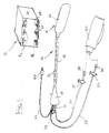
- Figure 1 is a perspective view of an insertable pickup probe in accordance with the present invention and an associated interface network.
- Figure 2 is a cross-sectional plan view of the distal balloon portion of the insertable pickup probe illustrated in Figure 1.
- Figure 3 is a cross-sectional elevational view of the distal end balloon portion of the probe.
- Figure 4 is a sectional view taken on line 4-4 of Figure 3.
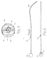
- Figure 5 is an elevational view of a steering mandrel for the probe.
- Figure 6 is a plan view of the steering mandrel.
- Figure 7 is a view similar to Figure 2 showing the distal balloon portion of a modified pickup probe according to the invention.
- Figure 8 is an elevational view of a mandrel used in the probe shown in Figure 7.
- Figures 9 and 10 are views showing alternative cross-sectional shapes for the mandrel.
- Figure 11 is a cross-section view on line XI-XI of Figure 7.
- an insertable colon pickup probe is shown in an assembled form at 10, and an interface network to which the probe connects is shown at 12.
- the pickup probe 10 is an MRI or NMR receiving device capable of imaging or gathering spectra from the human colon and surrounding tissue, but may also be used as the transmit coil for RF excitation.
- the probe 10 is used with the interface network 12 which provides the tuning, impedance matching, and decoupling functions.
- the probe 10 includes a shaft 14 which supports a patient interface balloon structure 16 at its distal end and a handle 18 located at the proximal end of the shaft 14.
- assembly 16 includes an internal pickup coil 20 and internal anterior and posterior inflation balloons 22 and 24, none of which are shown in Figure 1.
- the coil and internal balloons are accommodated, as will be described, in an outer balloon 26.
- Tubes 28, 30 for inflating the internal balloons extend from the respective balloons through shaft 14 and exit at the proximal end of handle 18.
- the tubes have respective inflation control stopcocks 32, 34 and connections 36, 38 for attaching same to an inflator device 40 such as a syringe or cuff.
- the receiving coil contained within the patient interface balloon structure 16 can be electrically connected to the interface 12 by an insulated interconnecting cable 42 which has a plug 44 at its proximal end for connection to terminal 46 located on the front of the interface network 12.
- the interface network 12 also includes a terminal 48 for providing a connection to a MRI scanner. Furthermore, the interface network 12 may include a switch 50 capable of being moved between an operating position and a tuning position or be designed such that it functions fully automatically. To display to the operator the mode of operation, indicator lights 52 or an LED readout are provided on the front of the interface network 12. In addition, a light 54 or an LED readout for indicating the occurrence of a probe failure is provided on the front of the interface network 12.
- a removable elongate rod-like steering mandrel 56 extends through the balloon structure 16 and shaft 14.
- the mandrel has an operating knob 58 at its proximal end.
- a stiffener tube 60 which is a permanent part of the structure and which may, for example, be supported in shaft 14 by an end plate 62 and a like end plate (not shown) at the proximal end of the shaft.
- the lead 42 for the pickup coil 20 extends through a lumen of the tube 60 and exits the tube through an aperture 64 adjacent the distal end of shaft 14. Outside of the aperture, lead 42 connects to coil 20 which is in the form of a loop occupying a substantial cross-sectional area of the outer balloon 26.
- the internal inflation balloons 22 and 24 embrace the coil 20 on its anterior and posterior sides and also occupy substantial areas of the outer balloon as shown in Figure 3.
- the inner balloons are connected at their distal inlet ends to the inflation tubes 28 and 30 which are shown diagrammatically only in Figure 2.
- the inflation tubes pass through apertures in end plate 62 and thence through the shaft 14.
- the inner balloons and coil 20 may be loosely held together as a sandwich-type package by an encircling cuff 66 shown dotted in Figures 2 and 3.
- the mandrel 56 which is of a stiff plastic or other material, also fits through the lumen of the stiffening tube 60. As shown in Figures 5 and 6, the mandrel is linear in plan view but has a J-like bend 68 at its distal end in elevational view. Also, the mandrel operating knob 58 has an indicator mark 70 to show a clinician inserting the probe the alignment of the mandrel. Further, as shown in Figure 1, the shaft has a lengthwise indicator stripe 72 (shown dotted for convenience only) substantially aligned with the plane of coil 20.
- the internal balloons 22 and 24 would be deflated to minimize the size of the structure 16, it being noted that outer balloon 26 is not inflated.
- the balloon structure may be given an orbital type twisting movement by rotation of the mandrel, should it be necessary to "steer" the probe along curves or bends in the anal tract or other intercavity passageway.
- the probe When the balloon structure is situated at a site to be investigated by MRI or NMR imaging, the probe is manipulated in order to orientate the coil substantially face on to an area of interest. Then, for optimal positioning of the coil relative to said area, the internal balloons may be differentially inflated with the balloon on that side of the coil which is further from the area of interest being inflated to a higher volume than the balloon which is on the side of the coil facing the area of interest. Differential inflation of the balloons is effected, for example, by opening and closing the respective stopcocks 32 and 34 to allow controlled quantities of air to be delivered to the respective balloons from the inflator device 40.
- Typical inflation volume for the balloons may, for example, be 40cc in each balloon for a center lumen position of the coil and 10cc in the anterior balloon and 50cc in the posterior balloon for an anterior position of the coil.
- Figures 7-11 show a modified probe structure in which the coil along with the internal balloons may be rotated within the outer balloon so as to allow in situ angular positioning of the coil when in position in a body cavity without having to rotate the probe as a whole when positioned within a patient.
- Equivalent reference numerals are used to denote parts which are equivalent to those in the previous embodiment.
- a proximal rotary bearing 80 is provided at the distal end of shaft 14 and a similar distal rotary bearing 82 is provided in a bearing support 83 within the outer balloon 16 at its distal end.
- Stiffener tube 60' is supported for rotation within the bearings 80 and 82, and a relatively stiff mandrel 56' with a proximal end operating knob 58' extends through shaft 14 and tube 60'.
- the pickup coil 20 and the internal anterior and posterior balloons 22 and 24 are constructed in like manner to the previous embodiment, but in this case they are taped together and also taped to the mandrel by tapes 66' so as to rotate together with the mandrel and stiffener tube as a unit within the outer balloon.
- the mandrel may have alternative cruciform cross-sectional shapes as shown in Figures 9 and 10 received in a correspondingly shaped lumen in the stiffener tube so that rotation of the mandrel by knob 58' when the probe is in situ in a body cavity is effective to rotate the internal balloon assembly within the outer balloon 16.
- the cruciform shape of the mandrel is also useful for indicating the angular position of the coil relative to the outer balloon along with indicator 70'.
- the outer balloon 16 may be disposable or covered by a disposable sheath or the like to allow for repeated use of the probe.
Abstract
Description
Claims (9)
- An insertable intracavitiy probe (10) for use in magnetic resonance imaging of a region of interest within a cavity of a patient comprising an elongate shaft (14) having a proximal end and a distal end, a handle (18) on the proximal end of the shaft (14), a balloon structure (16) on the distal end of the shaft (14) including therein a pickup coil (20) having an electrical lead (42) extending through the shaft (14) for connection to an interface network (12)
characterized in that
said balloon structure includes an outer balloon (26) and first and second inflatable inner balloons (22, 24) within the outer balloon (26), said inner balloons (22, 24) being located on first and second sides of said coil (20), respectively, sandwiching said coil (20) therebetween, and respective inflation tubes (28, 30) for inflating said inner balloons (22, 24) extending through said shaft (14). - The invention as defined in claim 1 including control means for selectively and individually controlling inflation pressure for said respective inner balloons (22, 24).
- The invention as defined in claim 2 characterized in that said control means includes a stopcock (32, 34) on each inflation tube (28, 30) and connector means (36, 38) for attaching said tube (28, 30) to an inflation source (40).
- The invention as defined in any one of claims 1-3 characterized in that said shaft (14) includes identifying means for indicating alignment of said coil (20).
- The invention as defined in claim 4 characterized in that said identifying means is a longitudinal stripe (72) or like mark on said shaft (14).
- Method of magnetic resonance imaging of a region of interest within a cavity of a patient using an inserted pickup probe (10) having an elongate shaft (14) with a balloon structure (16) at a distal end thereof including a pickup coil (20) therein,
characterized in that
the steps of inserting said balloon structure (16), including a pickup coil (20) and first and second internal inflatable balloons (22, 24) within said structure (16) embracing said coil (20) on opposite sides of said coil (20), respectively, into said cavity of a patient, positioning said balloon structure (16) proximate said area of interest, providing selective and independent inflation of said internal balloons (22, 24) to influence positioning of said coil (20) within said balloon structure (16) so as to optimally position said coil (20) in relation to said area of interest, and using said coil (20) for said imaging are included. - Method as defined in claim 6 characterized in that the steps of inserting said pickup probe (10) into said cavity, positioning said balloon structure (16) proximate said area of interest, selectively rotating said coil (20) within said balloon structure (16) to optimally position said coil (20) with respect to said area of interest and using said coil (20) for said imaging are included.
- Method as defined in any one of claims 6-7 characterized in that the step of influencing said coil (2) laterally within said balloon structure (16) to obtain optimum positioning of said coil (20) in ralation to said area of interest is included.
- Method as defined in claim 8 which further includes rotating said coil (20) and inner balloons (22, 24) with said balloon structure (16) to obtain optimal positioning of said coil (20).
Applications Claiming Priority (3)
| Application Number | Priority Date | Filing Date | Title |
|---|---|---|---|
| US07/760,463 US5307814A (en) | 1991-09-17 | 1991-09-17 | Externally moveable intracavity probe for MRI imaging and spectroscopy |
| US760463 | 1991-09-17 | ||
| EP92921089A EP0604587B1 (en) | 1991-09-17 | 1992-09-17 | Externally moveable intracavity probe for mri imaging and spectroscopy |
Related Parent Applications (1)
| Application Number | Title | Priority Date | Filing Date |
|---|---|---|---|
| EP92921089A Division EP0604587B1 (en) | 1991-09-17 | 1992-09-17 | Externally moveable intracavity probe for mri imaging and spectroscopy |
Publications (2)
| Publication Number | Publication Date |
|---|---|
| EP0848931A2 true EP0848931A2 (en) | 1998-06-24 |
| EP0848931A3 EP0848931A3 (en) | 1998-10-21 |
Family
ID=25059185
Family Applications (2)
| Application Number | Title | Priority Date | Filing Date |
|---|---|---|---|
| EP98104302A Withdrawn EP0848931A3 (en) | 1991-09-17 | 1992-09-17 | Externally moveable intracavity probe for MRI imaging and spectroscopy |
| EP92921089A Expired - Lifetime EP0604587B1 (en) | 1991-09-17 | 1992-09-17 | Externally moveable intracavity probe for mri imaging and spectroscopy |
Family Applications After (1)
| Application Number | Title | Priority Date | Filing Date |
|---|---|---|---|
| EP92921089A Expired - Lifetime EP0604587B1 (en) | 1991-09-17 | 1992-09-17 | Externally moveable intracavity probe for mri imaging and spectroscopy |
Country Status (6)
| Country | Link |
|---|---|
| US (1) | US5307814A (en) |
| EP (2) | EP0848931A3 (en) |
| JP (1) | JP2655940B2 (en) |
| CA (1) | CA2078536C (en) |
| DE (1) | DE69227912T2 (en) |
| WO (1) | WO1993005706A1 (en) |
Cited By (2)
| Publication number | Priority date | Publication date | Assignee | Title |
|---|---|---|---|---|
| EP1126783A1 (en) * | 1998-11-03 | 2001-08-29 | The Johns Hopkins University, School of Medicine, Office of Technology Licencing | Transesophageal magnetic resonance analysis method and apparatus |
| EP1277061A2 (en) * | 2000-03-30 | 2003-01-22 | The Uab Research Foundation | Intravaginal radiofrequency imaging device |
Families Citing this family (118)
| Publication number | Priority date | Publication date | Assignee | Title |
|---|---|---|---|---|
| US5632761A (en) * | 1991-05-29 | 1997-05-27 | Origin Medsystems, Inc. | Inflatable devices for separating layers of tissue, and methods of using |
| US5402788A (en) * | 1992-06-25 | 1995-04-04 | Olympus Optical Co., Ltd. | Diagnostic system using nuclear magnetic resonance phenomenon |
| NL9201965A (en) * | 1992-11-10 | 1994-06-01 | Draeger Med Electronics Bv | Invasive MRI transducer. |
| US5365928A (en) * | 1992-11-25 | 1994-11-22 | Medrad, Inc. | Endorectal probe with planar moveable MRI coil |
| US5400787A (en) * | 1993-11-24 | 1995-03-28 | Magna-Lab, Inc. | Inflatable magnetic resonance imaging sensing coil assembly positioning and retaining device and method for using the same |
| US5447156A (en) * | 1994-04-04 | 1995-09-05 | General Electric Company | Magnetic resonance (MR) active invasive devices for the generation of selective MR angiograms |
| US5607441A (en) * | 1995-03-24 | 1997-03-04 | Ethicon Endo-Surgery, Inc. | Surgical dissector |
| US5593418A (en) * | 1995-05-19 | 1997-01-14 | General Surgical Innovations, Inc. | Methods and devices for harvesting blood vessels with balloons |
| US5702417A (en) * | 1995-05-22 | 1997-12-30 | General Surgical Innovations, Inc. | Balloon loaded dissecting instruments |
| US5944734A (en) * | 1995-05-22 | 1999-08-31 | General Surgical Innovations, Inc. | Balloon dissecting instruments |
| US6004340A (en) * | 1995-05-22 | 1999-12-21 | General Surgical Innovations, Inc. | Balloon dissecting instruments |
| US7037317B2 (en) * | 1995-05-22 | 2006-05-02 | United States Surgical Corporation | Balloon dissecting instruments |
| US5993472A (en) * | 1995-05-22 | 1999-11-30 | General Surgical Innovations, Inc. | Balloon dissecting instruments |
| US5893866A (en) * | 1995-05-22 | 1999-04-13 | General Surgical Innovations, Inc. | Balloon dissecting instruments |
| US6179854B1 (en) | 1995-05-22 | 2001-01-30 | General Surgical Innovations, Inc. | Apparatus and method for dissecting and retracting elongate structures |
| US6596010B1 (en) | 1995-05-22 | 2003-07-22 | General Surgical Innovations, Inc. | Balloon dissecting instruments |
| US5979452A (en) * | 1995-06-07 | 1999-11-09 | General Surgical Innovations, Inc. | Endoscopic linton procedure using balloon dissectors and retractors |
| US5716321A (en) * | 1995-10-10 | 1998-02-10 | Conceptus, Inc. | Method for maintaining separation between a falloposcope and a tubal wall |
| US6675033B1 (en) | 1999-04-15 | 2004-01-06 | Johns Hopkins University School Of Medicine | Magnetic resonance imaging guidewire probe |
| US6263229B1 (en) | 1998-11-13 | 2001-07-17 | Johns Hopkins University School Of Medicine | Miniature magnetic resonance catheter coils and related methods |
| US7236816B2 (en) * | 1996-04-25 | 2007-06-26 | Johns Hopkins University | Biopsy and sampling needle antennas for magnetic resonance imaging-guided biopsies |
| US6549800B1 (en) | 1996-04-25 | 2003-04-15 | Johns Hopkins Unversity School Of Medicine | Methods for in vivo magnetic resonance imaging |
| US6628980B2 (en) | 2000-03-24 | 2003-09-30 | Surgi-Vision, Inc. | Apparatus, systems, and methods for in vivo magnetic resonance imaging |
| US6898454B2 (en) | 1996-04-25 | 2005-05-24 | The Johns Hopkins University | Systems and methods for evaluating the urethra and the periurethral tissues |
| WO1998052461A1 (en) * | 1997-05-21 | 1998-11-26 | Cardiac M.R.I., Inc. | Cardiac mri with an internal receiving coil and an external receiving coil |
| JPH11225984A (en) * | 1998-02-16 | 1999-08-24 | Toshiba Corp | Probe for mri |
| US6463317B1 (en) * | 1998-05-19 | 2002-10-08 | Regents Of The University Of Minnesota | Device and method for the endovascular treatment of aneurysms |
| US8244370B2 (en) | 2001-04-13 | 2012-08-14 | Greatbatch Ltd. | Band stop filter employing a capacitor and an inductor tank circuit to enhance MRI compatibility of active medical devices |
| US6701176B1 (en) * | 1998-11-04 | 2004-03-02 | Johns Hopkins University School Of Medicine | Magnetic-resonance-guided imaging, electrophysiology, and ablation |
| US7844319B2 (en) * | 1998-11-04 | 2010-11-30 | Susil Robert C | Systems and methods for magnetic-resonance-guided interventional procedures |
| US7848788B2 (en) | 1999-04-15 | 2010-12-07 | The Johns Hopkins University | Magnetic resonance imaging probe |
| WO2001056469A2 (en) | 2000-02-01 | 2001-08-09 | Surgi-Vision, Inc. | Magnetic resonance imaging transseptal needle antenna |
| GB0006207D0 (en) * | 2000-03-16 | 2000-05-03 | Picker Nordstar Oy | Nuclear magnetic resonance apparatus and method |
| US8565860B2 (en) | 2000-08-21 | 2013-10-22 | Biosensors International Group, Ltd. | Radioactive emission detector equipped with a position tracking system |
| US8909325B2 (en) | 2000-08-21 | 2014-12-09 | Biosensors International Group, Ltd. | Radioactive emission detector equipped with a position tracking system and utilization thereof with medical systems and in medical procedures |
| US8489176B1 (en) | 2000-08-21 | 2013-07-16 | Spectrum Dynamics Llc | Radioactive emission detector equipped with a position tracking system and utilization thereof with medical systems and in medical procedures |
| US6377048B1 (en) | 2000-11-08 | 2002-04-23 | Topspin Medical (Israel) Limited | Magnetic resonance imaging device for operation in external static magnetic fields |
| US6871086B2 (en) * | 2001-02-15 | 2005-03-22 | Robin Medical Inc. | Endoscopic examining apparatus particularly useful in MRI, a probe useful in such apparatus, and a method of making such probe |
| US8457760B2 (en) | 2001-04-13 | 2013-06-04 | Greatbatch Ltd. | Switched diverter circuits for minimizing heating of an implanted lead and/or providing EMI protection in a high power electromagnetic field environment |
| US8989870B2 (en) * | 2001-04-13 | 2015-03-24 | Greatbatch Ltd. | Tuned energy balanced system for minimizing heating and/or to provide EMI protection of implanted leads in a high power electromagnetic field environment |
| US20070088416A1 (en) | 2001-04-13 | 2007-04-19 | Surgi-Vision, Inc. | Mri compatible medical leads |
| US8600519B2 (en) * | 2001-04-13 | 2013-12-03 | Greatbatch Ltd. | Transient voltage/current protection system for electronic circuits associated with implanted leads |
| US8977355B2 (en) | 2001-04-13 | 2015-03-10 | Greatbatch Ltd. | EMI filter employing a capacitor and an inductor tank circuit having optimum component values |
| WO2002083016A1 (en) | 2001-04-13 | 2002-10-24 | Surgi-Vision, Inc. | Systems and methods for magnetic-resonance-guided interventional procedures |
| US8219208B2 (en) | 2001-04-13 | 2012-07-10 | Greatbatch Ltd. | Frequency selective passive component networks for active implantable medical devices utilizing an energy dissipating surface |
| US9295828B2 (en) | 2001-04-13 | 2016-03-29 | Greatbatch Ltd. | Self-resonant inductor wound portion of an implantable lead for enhanced MRI compatibility of active implantable medical devices |
| US8509913B2 (en) * | 2001-04-13 | 2013-08-13 | Greatbatch Ltd. | Switched diverter circuits for minimizing heating of an implanted lead and/or providing EMI protection in a high power electromagnetic field environment |
| US20040138702A1 (en) * | 2001-05-31 | 2004-07-15 | Kenneth Peartree | Balloon cannula with over-center clamp |
| US20040225213A1 (en) * | 2002-01-22 | 2004-11-11 | Xingwu Wang | Magnetic resonance imaging coated assembly |
| US20050260331A1 (en) * | 2002-01-22 | 2005-11-24 | Xingwu Wang | Process for coating a substrate |
| JP4437073B2 (en) * | 2002-05-16 | 2010-03-24 | メドラッド インコーポレーテッド | System and method for obtaining images and spectra of intracavitary structures using a 3.0 Tesla magnetic resonance system |
| WO2003098234A2 (en) * | 2002-05-17 | 2003-11-27 | Mr Instruments, Inc. | A cavity resonator for mr systems |
| US6904307B2 (en) | 2002-05-29 | 2005-06-07 | Surgi-Vision, Inc. | Magnetic resonance probes |
| DE10257909A1 (en) | 2002-12-11 | 2004-07-08 | Siemens Ag | Local coil for improving magnetic resonance imaging in the lower skull comprises a flexible base body in which the coil is imbedded so that it can be inserted through the nostril before springing out in the nasal cavity |
| US7967835B2 (en) * | 2003-05-05 | 2011-06-28 | Tyco Healthcare Group Lp | Apparatus for use in fascial cleft surgery for opening an anatomic space |
| WO2008010227A2 (en) | 2006-07-19 | 2008-01-24 | Spectrum Dynamics Llc | Imaging protocols |
| WO2005067383A2 (en) | 2004-01-13 | 2005-07-28 | Spectrum Dynamics Llc | Multi-dimensional image reconstruction |
| US8571881B2 (en) | 2004-11-09 | 2013-10-29 | Spectrum Dynamics, Llc | Radiopharmaceutical dispensing, administration, and imaging |
| US7968851B2 (en) | 2004-01-13 | 2011-06-28 | Spectrum Dynamics Llc | Dynamic spect camera |
| US9470801B2 (en) | 2004-01-13 | 2016-10-18 | Spectrum Dynamics Llc | Gating with anatomically varying durations |
| US8586932B2 (en) | 2004-11-09 | 2013-11-19 | Spectrum Dynamics Llc | System and method for radioactive emission measurement |
| IL161554A0 (en) * | 2004-04-22 | 2004-09-27 | Gali Tech Ltd | Catheter |
| US7496397B2 (en) * | 2004-05-06 | 2009-02-24 | Boston Scientific Scimed, Inc. | Intravascular antenna |
| EP1778957A4 (en) | 2004-06-01 | 2015-12-23 | Biosensors Int Group Ltd | Radioactive-emission-measurement optimization to specific body structures |
| EP1805525A2 (en) * | 2004-10-18 | 2007-07-11 | Topspin Medical (Israel) Limited | Expanding imaging probe |
| EP1827505A4 (en) | 2004-11-09 | 2017-07-12 | Biosensors International Group, Ltd. | Radioimaging |
| US8615405B2 (en) | 2004-11-09 | 2013-12-24 | Biosensors International Group, Ltd. | Imaging system customization using data from radiopharmaceutical-associated data carrier |
| US9316743B2 (en) | 2004-11-09 | 2016-04-19 | Biosensors International Group, Ltd. | System and method for radioactive emission measurement |
| US9943274B2 (en) | 2004-11-09 | 2018-04-17 | Spectrum Dynamics Medical Limited | Radioimaging using low dose isotope |
| US8423125B2 (en) | 2004-11-09 | 2013-04-16 | Spectrum Dynamics Llc | Radioimaging |
| JP4848377B2 (en) * | 2004-11-15 | 2011-12-28 | メドラッド インコーポレーテッド | Intracavity probe and its interface used to obtain images and spectra of intraluminal structures using a high-region magnetic resonance system |
| US20060122488A1 (en) * | 2004-11-18 | 2006-06-08 | Abdol-Mohammad Kajbafzadeh | Urodynamic diagnostic method and system |
| DE102005000761B4 (en) * | 2005-01-04 | 2008-05-21 | Siemens Ag | Intracorporeal endolocular coil for recording magnetic resonance signals |
| US8556851B2 (en) * | 2005-07-05 | 2013-10-15 | Angioslide Ltd. | Balloon catheter |
| US9439662B2 (en) | 2005-07-05 | 2016-09-13 | Angioslide Ltd. | Balloon catheter |
| US8644910B2 (en) | 2005-07-19 | 2014-02-04 | Biosensors International Group, Ltd. | Imaging protocols |
| US8837793B2 (en) | 2005-07-19 | 2014-09-16 | Biosensors International Group, Ltd. | Reconstruction stabilizer and active vision |
| US7659719B2 (en) * | 2005-11-25 | 2010-02-09 | Mr Instruments, Inc. | Cavity resonator for magnetic resonance systems |
| US20100191306A1 (en) * | 2006-01-25 | 2010-07-29 | Greatbatch Ltd. | Transient voltage suppression circuit for an implanted rfid chip |
| US8894974B2 (en) | 2006-05-11 | 2014-11-25 | Spectrum Dynamics Llc | Radiopharmaceuticals for diagnosis and therapy |
| US8903505B2 (en) | 2006-06-08 | 2014-12-02 | Greatbatch Ltd. | Implantable lead bandstop filter employing an inductive coil with parasitic capacitance to enhance MRI compatibility of active medical devices |
| US20080086050A1 (en) * | 2006-10-09 | 2008-04-10 | Medrad, Inc. | Mri hyperthermia treatment systems, methods and devices, endorectal coil |
| US8610075B2 (en) | 2006-11-13 | 2013-12-17 | Biosensors International Group Ltd. | Radioimaging applications of and novel formulations of teboroxime |
| WO2008075362A2 (en) | 2006-12-20 | 2008-06-26 | Spectrum Dynamics Llc | A method, a system, and an apparatus for using and processing multidimensional data |
| DE102007046169A1 (en) * | 2007-09-26 | 2009-04-09 | Schleifring Und Apparatebau Gmbh | Endorectal coil for magnetic resonance imaging |
| US8521253B2 (en) | 2007-10-29 | 2013-08-27 | Spectrum Dynamics Llc | Prostate imaging |
| US9108066B2 (en) | 2008-03-20 | 2015-08-18 | Greatbatch Ltd. | Low impedance oxide resistant grounded capacitor for an AIMD |
| US10080889B2 (en) | 2009-03-19 | 2018-09-25 | Greatbatch Ltd. | Low inductance and low resistance hermetically sealed filtered feedthrough for an AIMD |
| CA2728845A1 (en) | 2008-07-02 | 2010-01-07 | Angioslide Ltd. | Balloon catheter system and methods of use thereof |
| WO2010056911A1 (en) * | 2008-11-12 | 2010-05-20 | Medrad, Inc. | Quadrature endorectal coils and interface devices therefor |
| US8447414B2 (en) * | 2008-12-17 | 2013-05-21 | Greatbatch Ltd. | Switched safety protection circuit for an AIMD system during exposure to high power electromagnetic fields |
| US8095224B2 (en) * | 2009-03-19 | 2012-01-10 | Greatbatch Ltd. | EMI shielded conduit assembly for an active implantable medical device |
| US9439735B2 (en) | 2009-06-08 | 2016-09-13 | MRI Interventions, Inc. | MRI-guided interventional systems that can track and generate dynamic visualizations of flexible intrabody devices in near real time |
| US8396532B2 (en) | 2009-06-16 | 2013-03-12 | MRI Interventions, Inc. | MRI-guided devices and MRI-guided interventional systems that can track and generate dynamic visualizations of the devices in near real time |
| US8338788B2 (en) | 2009-07-29 | 2012-12-25 | Spectrum Dynamics Llc | Method and system of optimized volumetric imaging |
| WO2011062971A2 (en) * | 2009-11-17 | 2011-05-26 | Brigham And Women's Hospital, Inc. | Catheter device with local magnetic resonance imaging coil and methods for use thereof |
| US8610435B2 (en) * | 2009-11-24 | 2013-12-17 | Medrad, Inc. | Focus coil array and interface devices therefor |
| US8882763B2 (en) | 2010-01-12 | 2014-11-11 | Greatbatch Ltd. | Patient attached bonding strap for energy dissipation from a probe or a catheter during magnetic resonance imaging |
| WO2011089599A1 (en) | 2010-01-19 | 2011-07-28 | Angioslide Ltd. | Balloon catheter system and methods of making and use thereof |
| KR20130045889A (en) | 2010-07-01 | 2013-05-06 | 메드라드, 인크. | Multi-channel endorectal coils and interface devices therefor |
| US10272252B2 (en) | 2016-11-08 | 2019-04-30 | Greatbatch Ltd. | Hermetic terminal for an AIMD having a composite brazed conductive lead |
| US11198014B2 (en) | 2011-03-01 | 2021-12-14 | Greatbatch Ltd. | Hermetically sealed filtered feedthrough assembly having a capacitor with an oxide resistant electrical connection to an active implantable medical device housing |
| US10350421B2 (en) | 2013-06-30 | 2019-07-16 | Greatbatch Ltd. | Metallurgically bonded gold pocket pad for grounding an EMI filter to a hermetic terminal for an active implantable medical device |
| US9931514B2 (en) | 2013-06-30 | 2018-04-03 | Greatbatch Ltd. | Low impedance oxide resistant grounded capacitor for an AIMD |
| US9427596B2 (en) | 2013-01-16 | 2016-08-30 | Greatbatch Ltd. | Low impedance oxide resistant grounded capacitor for an AIMD |
| US10596369B2 (en) | 2011-03-01 | 2020-03-24 | Greatbatch Ltd. | Low equivalent series resistance RF filter for an active implantable medical device |
| US20130090649A1 (en) * | 2011-10-11 | 2013-04-11 | Boston Scientific Scimed, Inc. | Device and methods for renal nerve modulation |
| CN104105525A (en) * | 2011-12-02 | 2014-10-15 | 赛欧血管有限公司 | Balloon catheter system |
| BR112014030216A2 (en) | 2012-06-07 | 2017-06-27 | Koninklijke Philips Nv | local radiofrequency coil of magnetic resonance; magnetic resonance system; method for imaging a region with magnetic resonance imaging; computer readable non-transient media; and system |
| CN105025968A (en) | 2012-12-04 | 2015-11-04 | 安乔斯里德公司 | Balloon catheter and methods of use thereof |
| USRE46699E1 (en) | 2013-01-16 | 2018-02-06 | Greatbatch Ltd. | Low impedance oxide resistant grounded capacitor for an AIMD |
| DE102013109660A1 (en) | 2013-09-04 | 2015-03-05 | Hubert Noras | Rectal coil for magnetic resonance tomography |
| JP6341532B2 (en) * | 2014-03-20 | 2018-06-13 | テルモ株式会社 | Living tube placement tube |
| DE102014213857B4 (en) * | 2014-07-16 | 2016-03-03 | Siemens Aktiengesellschaft | Device with MR coil |
| US20200037917A1 (en) * | 2016-10-12 | 2020-02-06 | The Brigham And Women's Hospital, Inc. | Deployable local magnetic resonance imaging coil and methods for use thereof |
| US10249415B2 (en) | 2017-01-06 | 2019-04-02 | Greatbatch Ltd. | Process for manufacturing a leadless feedthrough for an active implantable medical device |
| US10905888B2 (en) | 2018-03-22 | 2021-02-02 | Greatbatch Ltd. | Electrical connection for an AIMD EMI filter utilizing an anisotropic conductive layer |
| US10912945B2 (en) | 2018-03-22 | 2021-02-09 | Greatbatch Ltd. | Hermetic terminal for an active implantable medical device having a feedthrough capacitor partially overhanging a ferrule for high effective capacitance area |
Citations (2)
| Publication number | Priority date | Publication date | Assignee | Title |
|---|---|---|---|---|
| EP0385367A1 (en) * | 1989-02-27 | 1990-09-05 | Medrad Inc. | Intracavity probe and interface device for MRI imaging and spectroscopy |
| US4960106A (en) * | 1987-04-28 | 1990-10-02 | Olympus Optical Co., Ltd. | Endoscope apparatus |
Family Cites Families (25)
| Publication number | Priority date | Publication date | Assignee | Title |
|---|---|---|---|---|
| US2085644A (en) * | 1935-04-29 | 1937-06-29 | Bert J Ferciot | Rectal electrode |
| US2126257A (en) * | 1935-12-26 | 1938-08-09 | Elizabeth Kauffman | Electromedical instrument |
| US4276874A (en) * | 1978-11-15 | 1981-07-07 | Datascope Corp. | Elongatable balloon catheter |
| US4338942A (en) * | 1980-10-20 | 1982-07-13 | Fogarty Thomas J | Dilatation catherter apparatus |
| JPS6190525A (en) * | 1984-10-11 | 1986-05-08 | Mitsubishi Electric Corp | Transmitter of nuclear magnetic resonance imaging system |
| US4764726A (en) * | 1985-08-05 | 1988-08-16 | Picker International, Inc. | Low distortion RF switching circuit without DC bias |
| US4920318A (en) * | 1985-08-14 | 1990-04-24 | Picker International, Inc. | Surface coil system for magnetic resonance imaging |
| JPS62286451A (en) * | 1986-06-05 | 1987-12-12 | 三菱電機株式会社 | Magnetic resonance receiving probe |
| IT8629545V0 (en) * | 1986-06-12 | 1986-06-12 | Fina Ernesto | SET BALLOON URETERAL CATHETER BALLOON FOR EXTRACTION OF URETERAL STONES |
| EP0256370A1 (en) * | 1986-08-12 | 1988-02-24 | Siemens Aktiengesellschaft | Antenna arrangement for exciting and recording nuclear magnetic resonance |
| US4775371A (en) * | 1986-09-02 | 1988-10-04 | Advanced Cardiovascular Systems, Inc. | Stiffened dilatation catheter and method of manufacture |
| US4886506A (en) * | 1986-12-23 | 1989-12-12 | Baxter Travenol Laboratories, Inc. | Soft tip catheter |
| US5050607A (en) * | 1987-03-04 | 1991-09-24 | Huntington Medical Research Institutes | High resolution magnetic resonance imaging of body cavities |
| US5035231A (en) * | 1987-04-27 | 1991-07-30 | Olympus Optical Co., Ltd. | Endoscope apparatus |
| JP2565911B2 (en) * | 1987-07-15 | 1996-12-18 | オリンパス光学工業株式会社 | NMR measurement endoscope system |
| JPS63270036A (en) * | 1987-04-30 | 1988-11-08 | Toshiba Corp | Magnetic resonance imaging apparatus |
| US5071406A (en) * | 1987-05-06 | 1991-12-10 | Jang G David | Limacon geometry balloon angioplasty catheter systems |
| US4793351A (en) * | 1987-06-15 | 1988-12-27 | Mansfield Scientific, Inc. | Multi-lumen balloon catheter |
| US4989608A (en) * | 1987-07-02 | 1991-02-05 | Ratner Adam V | Device construction and method facilitating magnetic resonance imaging of foreign objects in a body |
| US4917102A (en) * | 1988-09-14 | 1990-04-17 | Advanced Cardiovascular Systems, Inc. | Guidewire assembly with steerable adjustable tip |
| US5090957A (en) * | 1988-10-05 | 1992-02-25 | Abiomed, Inc. | Intraaortic balloon insertion |
| US4943275A (en) * | 1988-10-14 | 1990-07-24 | Abiomed Limited Partnership | Insertable balloon with curved support |
| US5104377A (en) * | 1989-08-10 | 1992-04-14 | C. R. Bard, Inc. | Uterine access device with automatic cervical adjustment |
| US5108370A (en) * | 1989-10-03 | 1992-04-28 | Paul Walinsky | Perfusion balloon catheter |
| US5116305A (en) * | 1990-02-01 | 1992-05-26 | Abiomed, Inc. | Curved intra aortic balloon with non-folding inflated balloon membrane |
-
1991
- 1991-09-17 US US07/760,463 patent/US5307814A/en not_active Expired - Lifetime
-
1992
- 1992-09-17 DE DE69227912T patent/DE69227912T2/en not_active Expired - Lifetime
- 1992-09-17 EP EP98104302A patent/EP0848931A3/en not_active Withdrawn
- 1992-09-17 EP EP92921089A patent/EP0604587B1/en not_active Expired - Lifetime
- 1992-09-17 CA CA002078536A patent/CA2078536C/en not_active Expired - Fee Related
- 1992-09-17 JP JP5506236A patent/JP2655940B2/en not_active Expired - Lifetime
- 1992-09-17 WO PCT/US1992/007891 patent/WO1993005706A1/en active IP Right Grant
Patent Citations (2)
| Publication number | Priority date | Publication date | Assignee | Title |
|---|---|---|---|---|
| US4960106A (en) * | 1987-04-28 | 1990-10-02 | Olympus Optical Co., Ltd. | Endoscope apparatus |
| EP0385367A1 (en) * | 1989-02-27 | 1990-09-05 | Medrad Inc. | Intracavity probe and interface device for MRI imaging and spectroscopy |
Cited By (4)
| Publication number | Priority date | Publication date | Assignee | Title |
|---|---|---|---|---|
| EP1126783A1 (en) * | 1998-11-03 | 2001-08-29 | The Johns Hopkins University, School of Medicine, Office of Technology Licencing | Transesophageal magnetic resonance analysis method and apparatus |
| EP1126783A4 (en) * | 1998-11-03 | 2006-03-22 | Univ Johns Hopkins Med | Transesophageal magnetic resonance analysis method and apparatus |
| EP1277061A2 (en) * | 2000-03-30 | 2003-01-22 | The Uab Research Foundation | Intravaginal radiofrequency imaging device |
| EP1277061A4 (en) * | 2000-03-30 | 2003-04-16 | Uab Research Foundation | Intravaginal radiofrequency imaging device |
Also Published As
| Publication number | Publication date |
|---|---|
| CA2078536A1 (en) | 1993-03-18 |
| EP0848931A3 (en) | 1998-10-21 |
| DE69227912T2 (en) | 1999-07-01 |
| JP2655940B2 (en) | 1997-09-24 |
| EP0604587B1 (en) | 1998-12-16 |
| DE69227912D1 (en) | 1999-01-28 |
| WO1993005706A1 (en) | 1993-04-01 |
| JPH07502909A (en) | 1995-03-30 |
| CA2078536C (en) | 1996-07-02 |
| US5307814A (en) | 1994-05-03 |
| EP0604587A4 (en) | 1994-08-10 |
| EP0604587A1 (en) | 1994-07-06 |
Similar Documents
| Publication | Publication Date | Title |
|---|---|---|
| US5307814A (en) | Externally moveable intracavity probe for MRI imaging and spectroscopy | |
| CA2079974C (en) | Probe for mri imaging and spectroscopy particularly in the cervical region | |
| EP0385367B1 (en) | Intracavity probe and interface device for MRI imaging and spectroscopy | |
| US5365928A (en) | Endorectal probe with planar moveable MRI coil | |
| US5476095A (en) | Intracavity probe and interface device for MRI imaging and spectroscopy | |
| US5622169A (en) | Apparatus and method for locating a medical tube in the body of a patient | |
| US5050607A (en) | High resolution magnetic resonance imaging of body cavities | |
| JP4437073B2 (en) | System and method for obtaining images and spectra of intracavitary structures using a 3.0 Tesla magnetic resonance system | |
| WO1998052461A1 (en) | Cardiac mri with an internal receiving coil and an external receiving coil | |
| EP0919824A2 (en) | MRI endocavitary RF coils | |
| US20020050819A1 (en) | Expandable MRI receiving coil | |
| EP0766093B1 (en) | Diagnostic system | |
| JP2575395B2 (en) | Antenna device for NMR measurement | |
| JPH11225984A (en) | Probe for mri | |
| JP4028643B2 (en) | MR endoscope | |
| JP2001190518A (en) | Magnetic resonance observing device | |
| JP4036399B2 (en) | MRI endoscope and MRI RF coil | |
| JP3234089B2 (en) | Magnetic resonance observation equipment | |
| JP2000262487A (en) | Mri device | |
| JP2575401B2 (en) | Antenna device for NMR measurement | |
| JPH06269421A (en) | Magnetic resonance observing apparatus | |
| JPH07213480A (en) | Cover type endoscope |
Legal Events
| Date | Code | Title | Description |
|---|---|---|---|
| PUAI | Public reference made under article 153(3) epc to a published international application that has entered the european phase |
Free format text: ORIGINAL CODE: 0009012 |
|
| 17P | Request for examination filed |
Effective date: 19980310 |
|
| AC | Divisional application: reference to earlier application |
Ref document number: 604587 Country of ref document: EP |
|
| AK | Designated contracting states |
Kind code of ref document: A2 Designated state(s): DE NL |
|
| PUAL | Search report despatched |
Free format text: ORIGINAL CODE: 0009013 |
|
| AK | Designated contracting states |
Kind code of ref document: A3 Designated state(s): DE NL |
|
| 17Q | First examination report despatched |
Effective date: 19991013 |
|
| STAA | Information on the status of an ep patent application or granted ep patent |
Free format text: STATUS: THE APPLICATION IS DEEMED TO BE WITHDRAWN |
|
| 18D | Application deemed to be withdrawn |
Effective date: 20000224 |