EP0844171A1 - Coupling system for control sticks. - Google Patents
Coupling system for control sticks. Download PDFInfo
- Publication number
- EP0844171A1 EP0844171A1 EP97402653A EP97402653A EP0844171A1 EP 0844171 A1 EP0844171 A1 EP 0844171A1 EP 97402653 A EP97402653 A EP 97402653A EP 97402653 A EP97402653 A EP 97402653A EP 0844171 A1 EP0844171 A1 EP 0844171A1
- Authority
- EP
- European Patent Office
- Prior art keywords
- control
- tilting
- coupling system
- sticks
- amplitude
- Prior art date
- Legal status (The legal status is an assumption and is not a legal conclusion. Google has not performed a legal analysis and makes no representation as to the accuracy of the status listed.)
- Granted
Links
Images

Classifications
-
- B—PERFORMING OPERATIONS; TRANSPORTING
- B64—AIRCRAFT; AVIATION; COSMONAUTICS
- B64C—AEROPLANES; HELICOPTERS
- B64C13/00—Control systems or transmitting systems for actuating flying-control surfaces, lift-increasing flaps, air brakes, or spoilers
- B64C13/02—Initiating means
- B64C13/04—Initiating means actuated personally
- B64C13/12—Dual control apparatus
-
- B—PERFORMING OPERATIONS; TRANSPORTING
- B64—AIRCRAFT; AVIATION; COSMONAUTICS
- B64C—AEROPLANES; HELICOPTERS
- B64C13/00—Control systems or transmitting systems for actuating flying-control surfaces, lift-increasing flaps, air brakes, or spoilers
- B64C13/02—Initiating means
- B64C13/04—Initiating means actuated personally
- B64C13/042—Initiating means actuated personally operated by hand
- B64C13/0421—Initiating means actuated personally operated by hand control sticks for primary flight controls
Definitions
- the present invention relates to a coupling system of minus two control sticks of a control device of a machine.
- a first series of known solutions recommends using mechanical systems, such as those described for example in documents US-5 137 234 and WO-95/03212.
- the object of the present invention is to remedy these drawbacks. It relates to a coupling system of at least two control handles, capable of being simple and space-saving way and generate coupling particularly effective, can be easily deactivated.
- said coupling system can be easily disabled, either manually by one of the operators, either automatically by an appropriate device, in particular by deactivating said calculation unit.
- the coupling system according to the invention can be simple and not very redundant.
- the actuator for example a motor electric or a gear motor, on the other control stick is controlled so as to bring the latter into a second tilting position, including the tilting amplitude is equal to the tilt amplitude of said first tilt position, multiplied by a coefficient determined.
- control sticks when said control sticks are actuated simultaneously, the present invention can be implemented work according to two different variants.
- each actuating member is controlled so as to generate in the control stick associated resistance to tilting as a function of the tilting amplitude of the other control stick. So although the control sticks can be tilted the operators are informed independently, by resistance to tilting, from any actuation simultaneous.
- said actuating members are controlled so as to bring said sleeves control in identical tilt positions, including the amplitude of tilting is a function of the respective forces applied by operators on said sleeves command, which allows controlled switching identical.
- the compliant coupling system to the invention preferably comprises, for each of said control sticks, at least one effort sensor capable of to measure the force applied by an operator on said control stick, and said coupling system is deactivated when the force applied to one of said sleeves of command is greater than a predefined value.
- said calculation unit receives the information relating to the tilting position of the sleeves control, in a first variant directly from said tilt sensors and, in a second variant, said central unit.
- the calculation unit is preferably integrated in said central unit.
- the coupling system according to the invention may also include a damping function.
- said coupling system includes at least one speed sensor associated with one of said control sleeves and capable of measuring the tilting speed of said control stick, and the actuating member associated with said control stick is commanded, during a tilting of the latter, to so as to generate a resistance to tilting, of value function of the tilting speed measured by said speed sensor.
- At least one independent damping means for example a shock absorber hydraulic, associated with one of said control sticks.
- the coupling system can also be applied to a machine, in particular an aircraft, susceptible to be piloted by an autopilot.
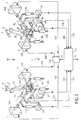
- Figure 1 schematically illustrates a coupling system according to the invention, in a first embodiment.
- Figure 2 schematically illustrates a coupling system according to the invention, in a second embodiment.
- the coupling system 1 is intended for coupling of control sticks 2A and 2B of a DC control of a machine, in this case an aircraft, by example a civil transport aircraft.
- control sticks 2A and 2B are produced in the form of manually actuated handles, respectively by the pilot and the co-pilot of the aircraft.
- said DC control device comprises identical elements, associated respectively with said sleeves 2A and 2B and described above.
- identical elements will be designated by the same number, followed either by the letter A, or the letter B, depending on whether the said elements are associated respectively with handle 2A or with handle 2B.
- the coupling system 1 according to the invention is applied said DC control device of known type, described previously.
- actuating members 13A, 13B, 14A and 14B are controlled by electronic regulation, of the usual type, not shown.
- said calculation unit CAL produced in the form of a separate unit receives position information tilting of the control sticks 2A and 2B, of the central processing unit UC via a link 17.
- coupling system 1 can be activated either only during certain phases of the flight, i.e. during the whole flight.
- said coupling system 1 further comprises, force sensors 18A and 18B respectively associated with control sticks 2A and 2B, capable of measuring the force applied by an operator on the control stick corresponding, and to transmit said measurements to the unit central UC respectively via links 19A and 19B.
- said coupling system 1 is deactivated when the force applied to one of the said control sticks 2A or 2B and measured by the sensor of associated effort 18A and 18B is greater than a value predefined.
- the coupling system 1 can also include a damping function.
- damping function can however also be implemented by independent depreciation means, by example a hydraulic or friction damper, of the type usual like known damping means 20A, 20B, 21A and 21B shown in Figures 1 and 2.
- independent depreciation means by example a hydraulic or friction damper, of the type usual like known damping means 20A, 20B, 21A and 21B shown in Figures 1 and 2.
- said damping function can be performed, in part by the CAL calculation unit and at least one actuator and a speed sensor, and in part by said means independent depreciation.
- the coupling system 1 according to the invention can also be applied to an aircraft with a Automatic pilot.
Abstract
Description
La présente invention concerne un système de couplage d'au moins deux manches de commande d'un dispositif de commande d'une machine.The present invention relates to a coupling system of minus two control sticks of a control device of a machine.
Quoique non exclusivement, elle s'applique plus particulièrement aux dispositifs de pilotage pour aéronef et elle sera ci-après plus spécialement décrite en référence à une telle application, étant bien entendu qu'il ne peut en résulter une limitation de la portée de l'invention.Although not exclusively, it applies more particularly piloting devices for aircraft and it will below more particularly described with reference to such application, it being understood that it cannot result a limitation of the scope of the invention.
On sait que de nombreuses machines, telles que des avions, des hélicoptères, des chars d'assaut, des engins de travaux publics, etc ..., sont pourvues d'un ensemble d'éléments commandés pouvant être actionnés à partir de l'un ou l'autre de deux postes de commande conjugués, contrôlés par deux opérateurs distincts (appelés pilote et copilote dans le cas de véhicules) et équipés chacun d'un manche de commande articulé de façon à pouvoir être basculé autour d'au moins un axe de basculement.We know that many machines, such as planes, helicopters, tanks, construction equipment public, etc ..., are provided with a set of elements controlled that can be operated from either two combined control stations, controlled by two separate operators (called pilot and co-pilot in the case vehicles) and each equipped with a control stick articulated so that it can be tilted around at least a tilting axis.
On connaít différentes solutions pour réaliser un tel couplage de manches de commande.We know different solutions to achieve such coupling of control sticks.
Une première série de solutions connues préconise d'utiliser des systèmes mécaniques, tels que ceux décrits par exemple dans les documents US-5 137 234 et WO-95/03212.A first series of known solutions recommends using mechanical systems, such as those described for example in documents US-5 137 234 and WO-95/03212.
Toutefois, de telles solutions de couplage mécanique présentent de très nombreux inconvénients, notamment en ce qui concerne la masse, l'encombrement et la maintenance.However, such mechanical coupling solutions have many disadvantages, particularly with regard to concerns mass, size and maintenance.
Un autre type de solution est décrit dans le document EP-0 384 806 de la demanderesse, qui divulgue un manche de commande pourvu d'un moteur électrique permettant, d'une part, de créer une sensation d'effort et permettant, d'autre part, dans le cas de l'association de deux manches de ce type, le suivi du basculement d'un manche par l'autre.Another type of solution is described in document EP-0 384 806 of the plaintiff, who discloses a sleeve of control provided with an electric motor allowing, part, to create a feeling of effort and allowing, on the other share, in the case of the combination of two rounds of this type, monitoring the tilting from one round to the other.
Un tel système de couplage électrique, qui permet de remédier au moins à certains des inconvénients des couplages mécaniques, présente toutefois un inconvénient majeur, à savoir le fait que la panne dudit système électrique fait perdre la sensation d'effort et en particulier le recentrage des manches de commande à une position neutre, en l'absence d'actionnement de ces derniers. Un tel inconvénient ne serait pas acceptable sans précautions particulières notamment pour un avion de transport civil.Such an electrical coupling system, which makes it possible to remedy at least to some of the drawbacks of couplings mechanical, however, has a major drawback, know the fact that the failure of said electrical system makes lose the feeling of effort and in particular refocusing control sticks in a neutral position, in the absence actuation of these. Such a drawback does not would not be acceptable without special precautions including for a civil transport aircraft.
Aussi, la mise en oeuvre d'une telle solution par exemple sur un avion de transport civil entraínerait des contraintes importantes, en ce qui concerne ledit système de couplage et notamment la redondance et la fiabilité des éléments le constituant, pour ne pas affecter la sécurité dudit avion.Also, the implementation of such a solution for example on a civil transport aircraft would cause constraints important, with regard to said coupling system and including redundancy and reliability of the elements constituent, so as not to affect the safety of said aircraft.
La présente invention a pour objet de remédier à ces inconvénients. Elle concerne un système de couplage d'au moins deux manches de commande, susceptible d'être réalisé de façon simple et peu encombrante et d'engendrer un couplage particulièrement efficace, pouvant être facilement désactivé.The object of the present invention is to remedy these drawbacks. It relates to a coupling system of at least two control handles, capable of being simple and space-saving way and generate coupling particularly effective, can be easily deactivated.
A cet effet, selon l'invention, ledit système de couplage électrique d'au moins deux manches de commande d'un dispositif de commande d'une machine, lesdits manches de commande étant destinés à être actionnés par des opérateurs distincts et étant chacun monté basculant autour d'au moins un axe de basculement, ledit système de couplage électrique comportant :
- pour chacun desdits manches de commande, au moins un capteur de basculement délivrant un signal électrique fonction de l'amplitude de basculement dudit manche de commande autour de son axe de basculement, de part et d'autre d'une position neutre ;
- pour chacun desdits manches de commande, au moins un organe d'actionnement susceptible d'agir, en fonction d'ordres de commande reçus de façon électrique, sur ledit manche de commande ; et
- des moyens de calcul recevant les signaux électriques engendrés par lesdits capteurs de basculement et susceptibles d'adresser de façon électrique en fonction desdits signaux électriques, d'une part, des ordres de commande à des organes de commande de la machine et, d'autre part, des ordres de commande auxdits organes d'actionnement,
- for each of said control sticks, at least one tilting sensor delivering an electrical signal as a function of the tilting amplitude of said control stick around its tilting axis, on either side of a neutral position;
- for each of said control sticks, at least one actuating member capable of acting, as a function of control orders received electrically, on said control stick; and
- calculation means receiving the electrical signals generated by said tilt sensors and capable of addressing electrically as a function of said electrical signals, on the one hand, control orders to machine control members and, on the other hand share, control orders to said actuating bodies,
Ainsi, grâce à l'invention, on obtient un système de couplage "actif" particulièrement efficace, comme précisé ci-dessous.Thus, thanks to the invention, a coupling system is obtained "active" particularly effective, as specified below.
De plus, ledit système de couplage peut être facilement désactivé, soit de façon manuelle par l'un des opérateurs, soit de façon automatique par un dispositif approprié, notamment en désactivant ladite unité de calcul.In addition, said coupling system can be easily disabled, either manually by one of the operators, either automatically by an appropriate device, in particular by deactivating said calculation unit.
En outre, en cas de panne du système de couplage conforme à l'invention, à fonctionnement électrique, la sensation d'effort qui est créée par lesdits moyens mécaniques ou hydrauliques générateurs d'une résistance au basculement est conservée, puisque lesdits moyens mécaniques sont indépendants dudit système de couplage, à la différence de la solution connue et précitée du document EP-0 384 806. Aussi, le système de couplage conforme à l'invention peut être réalisé de façon simple et peu redondante.In addition, in the event of a breakdown of the coupling system in accordance with the invention, electrically operated, the sensation of effort which is created by said mechanical means or hydraulic generators of a tilting resistance is preserved, since said mechanical means are independent of said coupling system, unlike the solution known and cited above from document EP-0 384 806. Also, the coupling system according to the invention can be simple and not very redundant.
De façon avantageuse, lorsqu'un seul desdits manches de commande est actionné, dans une première position de basculement, l'organe d'actionnement, par exemple un moteur électrique ou un motoréducteur, de l'autre manche de commande est commandé de manière à amener ce dernier dans une seconde position de basculement, dont l'amplitude de basculement est égale à l'amplitude de basculement de ladite première position de basculement, multipliée par un coefficient déterminé.Advantageously, when only one of said sleeves control is actuated, in a first tilting position, the actuator, for example a motor electric or a gear motor, on the other control stick is controlled so as to bring the latter into a second tilting position, including the tilting amplitude is equal to the tilt amplitude of said first tilt position, multiplied by a coefficient determined.
En outre, lorsque lesdits manches de commande sont actionnés simultanément, la présente invention peut être mise en oeuvre selon deux variantes différentes.In addition, when said control sticks are actuated simultaneously, the present invention can be implemented work according to two different variants.
Dans une première variante, chaque organe d'actionnement est commandé de manière à engendrer dans le manche de commande associé une résistance au basculement de valeur fonction de l'amplitude de basculement de l'autre manche de commande. Ainsi, bien que les manches de commande peuvent être basculés de façon indépendante, les opérateurs sont informés, par la résistance au basculement, de tout actionnement simultané.In a first variant, each actuating member is controlled so as to generate in the control stick associated resistance to tilting as a function of the tilting amplitude of the other control stick. So although the control sticks can be tilted the operators are informed independently, by resistance to tilting, from any actuation simultaneous.
Dans une seconde variante, lesdits organes d'actionnement sont commandés de manière à amener lesdits manches de commande dans des positions de basculement identiques, dont l'amplitude de basculement est fonction des efforts respectifs appliqués par les opérateurs sur lesdits manches de commande, ce qui permet d'obtenir des basculements commandés identiques.In a second variant, said actuating members are controlled so as to bring said sleeves control in identical tilt positions, including the amplitude of tilting is a function of the respective forces applied by operators on said sleeves command, which allows controlled switching identical.
Dans cette seconde variante, le système de couplage conforme à l'invention comporte de préférence, pour chacun desdits manches de commande, au moins un capteur d'effort susceptible de mesurer l'effort appliqué par un opérateur sur ledit manche de commande, et ledit système de couplage est désactivé lorsque l'effort appliqué sur l'un desdits manches de commande est supérieur à une valeur prédéfinie.In this second variant, the compliant coupling system to the invention preferably comprises, for each of said control sticks, at least one effort sensor capable of to measure the force applied by an operator on said control stick, and said coupling system is deactivated when the force applied to one of said sleeves of command is greater than a predefined value.
Selon l'invention, ladite unité de calcul reçoit les informations relatives à la position de basculement des manches de commande, dans une première variante directement desdits capteurs de basculement et, dans une seconde variante, de ladite unité centrale.According to the invention, said calculation unit receives the information relating to the tilting position of the sleeves control, in a first variant directly from said tilt sensors and, in a second variant, said central unit.
Dans ce dernier cas, l'unité de calcul est, de préférence, intégrée dans ladite unité centrale.In the latter case, the calculation unit is preferably integrated in said central unit.
Par ailleurs, le système de couplage conforme à l'invention peut également comporter une fonction d'amortissement.Furthermore, the coupling system according to the invention may also include a damping function.
A cet effet, dans un premier mode de réalisation, ledit système de couplage comporte au moins un capteur de vitesse associé à l'un desdits manches de commande et susceptible de mesurer la vitesse de basculement dudit manche de commande, et l'organe d'actionnement associé audit manche de commande est commandé, lors d'un basculement de ce dernier, de manière à engendrer une résistance au basculement, de valeur fonction de la vitesse de basculement mesurée par ledit capteur de vitesse.To this end, in a first embodiment, said coupling system includes at least one speed sensor associated with one of said control sleeves and capable of measuring the tilting speed of said control stick, and the actuating member associated with said control stick is commanded, during a tilting of the latter, to so as to generate a resistance to tilting, of value function of the tilting speed measured by said speed sensor.
Dans un second mode de réalisation, on prévoit au moins un moyen d'amortissement indépendant, par exemple un amortisseur hydraulique, associé à l'un desdits manches de commande.In a second embodiment, at least one independent damping means, for example a shock absorber hydraulic, associated with one of said control sticks.
Bien entendu, il est également envisageable de réaliser un amortissement utilisant simultanément lesdits premier et second modes de réalisation précités.Of course, it is also possible to carry out a depreciation simultaneously using said first and second aforementioned embodiments.
On notera que le système de couplage peut également être appliqué à une machine, notamment un aéronef, susceptible d'être pilotée par un pilote automatique.Note that the coupling system can also be applied to a machine, in particular an aircraft, susceptible to be piloted by an autopilot.
Dans ce cas, selon l'invention, ledit système de couplage comporte :
- dans une première variante, des moyens à action prioritaire qui maintiennent les manches de commande dans une position fixe déterminée, par exemple une position neutre, lorsque ladite machine est pilotée par ledit pilote automatique ; et
- dans une seconde variante, des moyens qui, lorsque ladite machine est pilotée par ledit pilote automatique, font suivre auxdits manches de commande des basculements, d'amplitude correspondant audit pilotage.
- in a first variant, priority action means which maintain the control sticks in a fixed fixed position, for example a neutral position, when said machine is controlled by said automatic pilot; and
- in a second variant, means which, when said machine is controlled by said automatic pilot, cause said control sleeves to switch over, of amplitude corresponding to said piloting.
Les figures du dessin annexé feront bien comprendre comment l'invention peut être réalisée. Sur ces figures, des références identiques désignent des éléments semblables. The figures in the accompanying drawing will make it clear how the invention can be realized. In these figures, references identical denote similar elements.
La figure 1 illustre schématiquement un système de couplage conforme à l'invention, dans un premier mode de réalisation.Figure 1 schematically illustrates a coupling system according to the invention, in a first embodiment.
La figure 2 illustre schématiquement un système de couplage conforme à l'invention, dans un second mode de réalisation.Figure 2 schematically illustrates a coupling system according to the invention, in a second embodiment.
Le système de couplage 1 conforme à l'invention et représenté
schématiquement sur les figures 1 et 2, respectivement
dans deux modes de réalisation différents, est destiné au
couplage de manches de commande 2A et 2B d'un dispositif de
commande DC d'une machine, en l'occurrence d'un aéronef, par
exemple un avion de transport civil.The coupling system 1 according to the invention and shown
schematically in Figures 1 and 2, respectively
in two different embodiments, is intended for
coupling of
De façon connue, lesdits manches de commande 2A et 2B sont
réalisés sous forme de poignées actionnables manuellement,
respectivement par le pilote et par le copilote de l'aéronef.In known manner, said
Pour piloter ledit aéronef en tangage et en roulis, lesdits manches de commande 2A et 2B qui sont orientés en position neutre ou de repos, longitudinalement suivant un axe Z-Z, peuvent être manoeuvrés :
- d'une part, vers l'avant et vers l'arrière, comme indiqué
par une double flèche
F , de manière à basculer autour d'un axe transversal X-X, ce qui permet de piloter l'aéronef en tangage ; et - d'autre part, vers la droite et vers la gauche, comme
indiqué par une double flèche
E , de manière à basculer autour d'un axe longitudinal Y-Y, ce qui permet de piloter l'aéronef en roulis.
- on the one hand, forwards and backwards, as indicated by a double arrow
F , so as to tilt around a transverse axis XX, which makes it possible to pilot the aircraft in pitch; and - on the other hand, to the right and to the left, as indicated by a double arrow
E , so as to tilt around a longitudinal axis YY, which makes it possible to control the aircraft in roll.
On notera que ledit dispositif de commande DC comporte des
éléments identiques, associés respectivement auxdits manches
de commande 2A et 2B et décrits ci-dessus. Pour des raisons
de simplification de la description, les éléments identiques
seront désignés par le même nombre, suivi soit de la lettre
A, soit de la lettre B, selon que lesdits éléments sont
associés respectivement au manche 2A ou au manche 2B.It will be noted that said DC control device comprises
identical elements, associated respectively with said
De façon connue, ledit dispositif de commande DC comporte, en plus desdits manches de commande 2A et 2B :
- un
mécanisme 3A ou 3B comportant une articulation, par exemple une rotule ou un cardan, permettant audit manche decommande 2A ou 2B de basculer autour de ses axes de basculement X-X et Y-Y ; - un capteur de
basculement 4A ou 4B détectant par l'intermédiaire d'une bielle 5A ou 5B le basculement du manche decommande 2A ou 2B autour de l'axe X-X, de part et d'autre de la position de repos selon Z-Z, et délivrant un signal électrique fonction de l'amplitude dudit basculement ; - un capteur de
basculement 6A ou 6B détectant par l'intermédiaire d'unebielle 7A ou 7B le basculement du manche decommande 2A ou 2B autour de l'axe Y-Y, de part et d'autre de la position de repos selon Z-Z, et délivrant un signal électrique fonction de l'amplitude dudit basculement ; - des moyens mécaniques 8A ou 8B engendrant une résistance
au basculement, lors du basculement dudit manche de
commande 2A ou 2B autour de l'axe X-X ; - des moyens mécaniques 9A ou 9B engendrant une résistance
au basculement, lors du basculement dudit manche de
commande 2A ou 2B autour de l'axe Y-Y, lesdits moyens mécaniques 8A, 8B, 9A et 9B pouvant par exemple être réalisés sous forme de bielles à ressort, de ressorts à lames ou de ciseaux à ressort ; et - une unité centrale UC, reliée par des
liaisons capteurs capteurs liaison 12.
- a
mechanism control handle - a
tilt sensor rod 5A or 5B, the tilting of thecontrol handle - a
tilt sensor rod control handle -
mechanical means control stick -
mechanical means control stick mechanical means - a central unit UC, connected by
links sensors sensors link 12.
Le système de couplage 1 conforme à l'invention est appliqué audit dispositif de commande DC de type connu, décrit précédemment.The coupling system 1 according to the invention is applied said DC control device of known type, described previously.
Selon l'invention, ledit système de couplage 1 comporte :
- pour chacun desdits manches de commande
2A ou 2B, des organes d'actionnement 13A et14A 14B susceptibles de faire basculer, en fonction d'ordres de basculement reçus, de façon électrique, ledit manche de commandeou 13B et2A ou 2B respectivement autour des axes de basculement X-X et Y-Y ; et - une unité de calcul CAL, susceptible d'être activée et
désactivée, recevant des informations relatives à la
position de basculement desdits manches de commande 2A et
2B et engendrant, lorsqu'elle est activée, lors de l'actionnement
(du basculement) d'au moins l'un desdits
manches de commande 2A et 2B, des ordres de basculement
transmis de façon électrique aux organes d'actionnement de
l'autre manche de commande
2A et 2B.
- for each of said control sticks 2A or 2B, actuating
members control stick - a calculation unit CAL, capable of being activated and deactivated, receiving information relating to the tilting position of said control sticks 2A and 2B and generating, when it is activated, upon actuation (of tilting) of at least one of said control sticks 2A and 2B, tilting orders transmitted electrically to the actuating members of the
other control stick
Selon l'invention, lesdits organes d'actionnement 13A, 13B, 14A et 14B qui sont commandés par l'unité de calcul CAL, respectivement par l'intermédiaire de liaisons 15A, 15B, 16A et 16B, peuvent être réalisés chacun sous forme :
- d'un motoréducteur ; ou
- d'un moteur électrique sans réducteur.
- a gear motor; or
- an electric motor without reducer.
De façon connue, lesdits organes d'actionnement 13A, 13B,
14A et 14B sont commandés au moyen d'une régulation électronique,
de type usuel, non représentée.In known manner, said
Dans les modes de réalisation représentés sur les figure 1
et 2, ladite unité de calcul CAL réalisée sous forme d'une
unité séparée reçoit les informations relatives à la position
de basculement des manches de commande 2A et 2B, de
l'unité centrale UC par l'intermédiaire d'une liaison 17.In the embodiments shown in FIG. 1
and 2, said calculation unit CAL produced in the form of a
separate unit receives position information
tilting of the control sticks 2A and 2B, of
the central processing unit UC via a
Ladite unité de calcul CAL peut toutefois être réalisée différemment, en particulier :
- elle peut être intégrée dans l'unité centrale UC ; ou
- elle peut être reliée directement aux capteurs 4A, 4B,
6A et 6B et donc être indépendante de ladite unité centrale UC.
- it can be integrated into the central processing unit UC; or
- it can be directly connected to
sensors
On notera que l'unité de calcul CAL, et donc le système de couplage 1, peuvent être désactivés :
- soit de façon manuelle, par l'un des opérateurs ;
- soit de façon automatique, par l'intermédiaire d'un moyen non représenté, par exemple en fonction de la valeur de paramètres mesurés.
- either manually, by one of the operators;
- either automatically, by means of a means not shown, for example as a function of the value of measured parameters.
Ainsi, le système de couplage 1 peut être activé soit uniquement pendant certaines phases du vol, soit pendant tout le vol.Thus, coupling system 1 can be activated either only during certain phases of the flight, i.e. during the whole flight.
Selon l'invention, ladite unité de calcul CAL commande, dans le mode de réalisation de la figure 1, les organes d'actionnement 13A, 13B, 14A et 14B de sorte que :
- lorsqu'un seul desdits manches de commande
2A ou 2B est basculé, autour d'un axe de basculement X-X ou Y-Y, dans une première position de basculement, l'organe d'actionnement de l'autre manche de commande, relatif au même axe de basculement, est commandé de manière à amener ce dernier dans une seconde position de basculement, dont l'amplitude de basculement est égale à l'amplitude de basculement de ladite première position de basculement, multipliée par un coefficient ; et - lorsque les deux manches de commande 2A et 2B sont basculés simultanément, chaque organe d'actionnement est commandé de manière à engendrer dans le manche de commande associé une résistance au basculement, de valeur fonction de l'amplitude de basculement de l'autre manche de commande.
- when only one of said control sticks 2A or 2B is tilted, about a tilting axis XX or YY, in a first tilting position, the actuating member of the other control stick, relative to the same axis tilting, is controlled so as to bring the latter into a second tilting position, the tilting amplitude of which is equal to the tilting amplitude of said first tilting position, multiplied by a coefficient; and
- when the two
control sticks
Selon l'invention, lors d'un actionnement ou basculement d'un seul manche, ledit coefficient peut :
- être égal à 1, de manière à obtenir un suivi fidèle du manche de commande non actionné ;
- être inférieur à 1, de sorte que le manche de commande non actionné suit le mouvement du manche de commande actionné, mais avec une amplitude de basculement réduite ; ou
- être supérieur à 1, de manière à obtenir un suivi avec une amplitude de basculement amplifiée.
- be equal to 1, so as to obtain faithful monitoring of the non-actuated control stick;
- be less than 1, so that the non-actuated control stick follows the movement of the actuated control stick, but with a reduced tilt amplitude; or
- be greater than 1, so as to obtain a follow-up with an amplitude of tilting amplified.
Dans un autre mode de réalisation, tel que représenté sur la figure 2, l'unité de calcul CAL commande les organes d'actionnement 13A, 13B, 14A et 14B de sorte que :
- lorsqu'un seul desdits manches de commande
2A ou 2B est actionné, la commande est réalisée de manière identique au mode de réalisation de la figure 1 ; - lorsque les deux manches de commande 2A et 2B sont actionnés
simultanément, les organes d'actionnement 13A, 13B,
14A et 14B sont commandés de manière à amener lesdits manches de commande 2A et 2B dans des positions de basculement identiques, dont l'amplitude de basculement est fonction des efforts respectifs appliqués par les opérateurs sur lesdits manches de commande2A et 2B.
- when only one of said control sticks 2A or 2B is actuated, the control is carried out in an identical manner to the embodiment of FIG. 1;
- when the two
control sticks actuating members
Dans ce cas, ledit système de couplage 1 comporte, de plus,
des capteurs d'effort 18A et 18B associés respectivement aux
manches de commande 2A et 2B, susceptibles de mesurer
l'effort appliqué par un opérateur sur le manche de commande
correspondant, et de transmettre lesdites mesures à l'unité
centrale UC respectivement par l'intermédiaire de liaisons
19A et 19B. In this case, said coupling system 1 further comprises,
Selon l'invention, dans ce cas, ledit système de couplage 1
est désactivé lorsque l'effort appliqué sur l'un desdits
manches de commande 2A ou 2B et mesuré par le capteur
d'effort associé 18A et 18B est supérieur à une valeur
prédéfinie.According to the invention, in this case, said coupling system 1
is deactivated when the force applied to one of the said
control sticks 2A or 2B and measured by the sensor
of associated
Ainsi, grâce à l'invention, on obtient un système de couplage "actif" particulièrement efficace.Thus, thanks to the invention, a coupling system is obtained "active" particularly effective.
De plus, en cas de panne dudit système de couplage 1 à
fonctionnement électrique, la sensation d'effort qui est
créée par les moyens mécaniques 8A, 8B, 9A et 9B indépendants
de l'unité de calcul CAL et des organes d'actionnement
13A, 13B, 14A et 14B, est maintenue.In addition, in the event of failure of said coupling system 1 to
electrical functioning, the feeling of effort which is
created by independent
Le système de couplage 1 peut également comporter une fonction d'amortissement.The coupling system 1 can also include a damping function.
Pour ce faire :
- ledit système 1 comporte des capteurs de vitesse susceptibles
de mesurer la vitesse de basculement des manches de
commande 2A et 2B autour des axes X-X et Y-Y.
Les capteurs 6A et 6B peuvent jouer ce rôle ; et - l'unité de calcul CAL commande, lors du basculement au
moins d'un desdits manches de commande
2A ou 2B autour d'un axe X-X ou Y-Y, l'organe d'actionnement correspondant 13A, 13B,14A ou 14B de manière à engendrer une résistance au basculement, de valeur fonction de la vitesse de basculement mesurée. Ce mode de réalisation permet de réaliser une fonction d'amortissement complexe.
- said system 1 includes speed sensors capable of measuring the tilting speed of the control sticks 2A and 2B around the axes XX and YY.
Sensors - the calculation unit CAL controls, when tilting at least one of said control sticks 2A or 2B around an axis XX or YY, the corresponding actuating
member
Cette fonction d'amortissement peut toutefois également être mise en oeuvre par un moyen d'amortissement indépendant, par exemple un amortisseur hydraulique ou à frottement, de type usuel comme les moyens d'amortissement connus 20A, 20B, 21A et 21B représentés sur les figures 1 et 2. This damping function can however also be implemented by independent depreciation means, by example a hydraulic or friction damper, of the type usual like known damping means 20A, 20B, 21A and 21B shown in Figures 1 and 2.
Bien entendu, dans un mode de réalisation particulier, ladite fonction d'amortissement peut être assurée, en partie par l'unité de calcul CAL et au moins un organe d'actionnement et un capteur de vitesse, et en partie par ledit moyen d'amortissement indépendant.Of course, in a particular embodiment, said damping function can be performed, in part by the CAL calculation unit and at least one actuator and a speed sensor, and in part by said means independent depreciation.
Bien entendu, le système de couplage 1 conforme à l'invention peut également être appliqué à un aéronef muni d'un pilote automatique.Of course, the coupling system 1 according to the invention can also be applied to an aircraft with a Automatic pilot.
Dans ce cas, ledit système de couplage 1 comporte :
- dans une première variante, des moyens non représentés à action prioritaire qui maintiennent les manches de commande 2A et 2B dans une position fixe déterminée, de préférence la position neutre selon l'axe Z-Z, lorsque l'aéronef est commandé par ledit pilote automatique ; et
- dans une seconde variante, des moyens également non représentés qui, lorsque l'aéronef est piloté par ledit pilote automatique, font suivre auxdits manches de commande 2A et 2B des basculements, d'amplitude correspondant audit pilotage.
- in a first variant, means not shown with priority action which maintain the control sticks 2A and 2B in a fixed fixed position, preferably the neutral position along the axis ZZ, when the aircraft is controlled by said automatic pilot; and
- in a second variant, means also not shown which, when the aircraft is piloted by said automatic pilot, cause said control sticks 2A and 2B to follow tiltings, of amplitude corresponding to said piloting.
Claims (14)
caractérisé en ce que, lorsqu'un seul desdits manches de commande (2A, 2B) est actionné, dans une première position de basculement, l'organe d'actionnement (13A, 13B, 14A, 14B) de l'autre manche de commande est commandé de manière à amener ce dernier dans une seconde position de basculement, dont l'amplitude de basculement est égale à l'amplitude de basculement de ladite première position de basculement, multipliée par un coefficient déterminé.Coupling system according to claim 1,
characterized in that, when only one of said control sticks (2A, 2B) is actuated, in a first tilting position, the actuating member (13A, 13B, 14A, 14B) of the other control stick is controlled so as to bring the latter into a second tilting position, the tilting amplitude of which is equal to the tilting amplitude of said first tilting position, multiplied by a determined coefficient.
caractérisé en ce que, lorsque lesdits manches de commande (2A, 2B) sont actionnés simultanément, chaque organe d'actionnement (13A, 13B, 14A, 14B) est commandé de manière à engendrer dans le manche de commande associé (2A, 2B) une résistance au basculement, de valeur fonction de l'amplitude de basculement de l'autre manche de commande.Coupling system according to one of claims 1 or 2,
characterized in that, when said control sticks (2A, 2B) are actuated simultaneously, each actuating member (13A, 13B, 14A, 14B) is controlled so as to generate in the associated control stick (2A, 2B) a resistance to tilting, of value depending on the tilting amplitude of the other control stick.
caractérisé en ce que, lorsque lesdits manches de commande (2A, 2B) sont actionnés simultanément, lesdits organes d'actionnement (13A, 13B, 14A, 14B) sont commandés de manière à amener lesdits manches de commande (2A, 2B) dans des positions de basculement identiques, dont l'amplitude de basculement est fonction des efforts respectifs appliqués par les opérateurs sur lesdits manches de commande (2A, 2B).Coupling system according to one of claims 1 or 2,
characterized in that, when said control sleeves (2A, 2B) are actuated simultaneously, said actuating members (13A, 13B, 14A, 14B) are controlled so as to bring said control sleeves (2A, 2B) into identical tilting positions, the tilting amplitude of which is a function of the respective forces applied by the operators to said control sticks (2A, 2B).
caractérisé en ce qu'il comporte, pour chacun desdits manches de commande (2A, 2B), au moins un capteur d'effort (18A, 18B) susceptible de mesurer l'effort appliqué par un opérateur sur ledit manche de commande (2A, 2B), et en ce que ledit système de couplage (1) est désactivé lorsque l'effort appliqué sur l'un desdits manches de commande (2A, 2B) est supérieur à une valeur prédéfinie.Coupling system according to claim 4,
characterized in that it comprises, for each of said control sticks (2A, 2B), at least one force sensor (18A, 18B) capable of measuring the force applied by an operator to said control stick (2A, 2B), and in that said coupling system (1) is deactivated when the force applied to one of said control sticks (2A, 2B) is greater than a predefined value.
caractérisé en ce que ledit organe d'actionnement (13A, 13B, 14A, 14B) est un moteur électrique.Coupling system according to any one of claims 1 to 5,
characterized in that said actuating member (13A, 13B, 14A, 14B) is an electric motor.
caractérisé en ce que ledit organe d'actionnement (13A, 13B, 14A, 14B) est un motoréducteur.Coupling system according to any one of claims 1 to 5,
characterized in that said actuating member (13A, 13B, 14A, 14B) is a geared motor.
caractérisé en ce que lesdits moyens de calcul (CAL, UC) comportent une unité de calcul (CAL) qui engendre les ordres de commande desdits organes d'actionnement (13A, 13B, 14A, 14B) et une unité centrale (UC) qui engendre les ordres de commande desdits organes de commande de la machine.Coupling system according to any one of the preceding claims,
characterized in that said calculation means (CAL, UC) comprise a calculation unit (CAL) which generates the control orders of said actuating members (13A, 13B, 14A, 14B) and a central unit (UC) which generates the control orders of said machine control members.
caractérisé en ce que ladite unité de calcul (CAL) reçoit les informations relatives à la position de basculement des manches de commande (2A, 2B), directement desdits capteurs de basculement (4A, 4B, 6A, 6B).Coupling system according to claim 8,
characterized in that said calculation unit (CAL) receives information relating to the tilting position of the control sticks (2A, 2B), directly from said tilting sensors (4A, 4B, 6A, 6B).
caractérisé en ce que ladite unité de calcul (CAL) reçoit les informations relatives à la position de basculement des manches de commande (2A, 2B), de ladite unité centrale (UC).Coupling system according to claim 8,
characterized in that said calculating unit (CAL) receives information relating to the tilting position of the control sticks (2A, 2B), from said central unit (UC).
caractérisé en ce qu'il comporte au moins un capteur de vitesse (4A, 4B, 6A, 6B) associé à l'un desdits manches de commande (2A, 2B) et susceptible de mesurer la vitesse de basculement dudit manche de commande (2A, 2B), et en ce que l'organe d'actionnement (13A, 13B, 14A, 14B) associé audit manche de commande (2A, 2B) est commandé, lors d'un basculement de ce dernier, de manière à engendrer une résistance au basculement, de valeur fonction de la vitesse de basculement mesurée par ledit capteur de vitesse (4A, 4B, 6A, 6B).Coupling system according to any one of the preceding claims,
characterized in that it comprises at least one speed sensor (4A, 4B, 6A, 6B) associated with one of said control sticks (2A, 2B) and capable of measuring the tilting speed of said control stick (2A , 2B), and in that the actuating member (13A, 13B, 14A, 14B) associated with said control handle (2A, 2B) is controlled, during a tilting of the latter, so as to generate a tilt resistance, value depending on the tilt speed measured by said speed sensor (4A, 4B, 6A, 6B).
caractérisé en ce qu'il comporte au moins un moyen d'amortissement indépendant (20A, 20B, 21A, 21B), associé à l'un desdits manches de commande (2A, 2B).Coupling system according to any one of the preceding claims,
characterized in that it comprises at least one independent damping means (20A, 20B, 21A, 21B), associated with one of said control sleeves (2A, 2B).
caractérisé en ce qu'il comporte des moyens à action prioritaire qui maintiennent les manches de commande (2A, 2B) dans une position fixe déterminée, lorsque ladite machine est pilotée par ledit pilote automatique. Coupling system according to any one of claims 1 to 12, for a machine capable of being controlled by an automatic pilot,
characterized in that it comprises priority action means which maintain the control sticks (2A, 2B) in a fixed fixed position, when said machine is controlled by said automatic pilot.
caractérisé en ce qu'il comporte des moyens qui, lorsque ladite machine est pilotée par ledit pilote automatique, font suivre auxdits manches de commande (2A, 2B) des basculements, d'amplitude correspondant audit pilotage.Coupling system according to any one of claims 1 to 12, for a machine capable of being controlled by an automatic pilot,
characterized in that it comprises means which, when said machine is controlled by said automatic pilot, cause said control sticks (2A, 2B) to follow tiltings, of amplitude corresponding to said piloting.
Applications Claiming Priority (2)
| Application Number | Priority Date | Filing Date | Title |
|---|---|---|---|
| FR9614289A FR2756392B1 (en) | 1996-11-22 | 1996-11-22 | CONTROL SLEEVE COUPLING SYSTEM |
| FR9614289 | 1996-11-22 |
Publications (2)
| Publication Number | Publication Date |
|---|---|
| EP0844171A1 true EP0844171A1 (en) | 1998-05-27 |
| EP0844171B1 EP0844171B1 (en) | 2004-07-21 |
Family
ID=9497908
Family Applications (1)
| Application Number | Title | Priority Date | Filing Date |
|---|---|---|---|
| EP97402653A Expired - Lifetime EP0844171B1 (en) | 1996-11-22 | 1997-11-06 | Coupling system for control sticks. |
Country Status (4)
| Country | Link |
|---|---|
| US (1) | US5900710A (en) |
| EP (1) | EP0844171B1 (en) |
| DE (1) | DE69729928T2 (en) |
| FR (1) | FR2756392B1 (en) |
Cited By (3)
| Publication number | Priority date | Publication date | Assignee | Title |
|---|---|---|---|---|
| FR2952447A1 (en) * | 2009-11-06 | 2011-05-13 | Ratier Figeac Soc | ELECTRONIC CONTROL DEVICE FOR OPERATING A CRUISE MONITORING DRIVER, STEERING DEVICE AND AIRCRAFT |
| EP2500265A1 (en) | 2011-03-18 | 2012-09-19 | Eurocopter | Cyclic joystick with mechanical transmission for controlling a rotorcraft, including a lever arm selectively amplified in the event of an emergency |
| CN107031825A (en) * | 2015-12-14 | 2017-08-11 | 空中客车运营简化股份公司 | Including the aircraft controller and CCU device of the pedal for being coupled to jack |
Families Citing this family (29)
| Publication number | Priority date | Publication date | Assignee | Title |
|---|---|---|---|---|
| US6572055B1 (en) | 1999-08-10 | 2003-06-03 | Bombardier Aerospace Corporation | Hydrostatic sidestick coupling |
| US6644600B1 (en) * | 2002-04-25 | 2003-11-11 | Rockwell Collins, Inc. | Method and system for providing manipulation restraining forces for a stick controller on an aircraft |
| CA2496776C (en) * | 2002-09-24 | 2010-11-30 | Bell Helicopter Textron Inc. | Rotorcraft control system with stepped mixing linkage |
| FR2847352B1 (en) * | 2002-11-18 | 2005-01-28 | Airbus France | AIRCRAFT FLIGHT CONTROL SYSTEM FOR AIRCRAFT HAVING DETECTION OF OSCILLATORY STEERING COUPLINGS AND STEERING BODY FOR SUCH A SYSTEM |
| FR2888009B1 (en) * | 2005-06-30 | 2007-09-07 | Dassault Aviat | CONTROL DEVICE HAVING TWO SLEEVES COUPLED TO ALLOW PLACEMENT OF CONTROLLED ORGANS IN DESIRED POSITIONS |
| DE202005015434U1 (en) | 2005-09-30 | 2007-02-08 | Liebherr-Aerospace Lindenberg Gmbh | Controller with control stick for aircraft has 2 control shafts rotatably mounted in fixed position on common frame, joint with free-running device per control shaft for tilting control stick in plane parallel to respective control shaft |
| US20070235594A1 (en) * | 2006-04-06 | 2007-10-11 | Honeywell International, Inc. | Pilot flight control stick feedback system |
| US7843426B2 (en) * | 2006-11-15 | 2010-11-30 | Honeywell International Inc. | Active human-machine interface system including interposed sector gears |
| GB0714916D0 (en) * | 2007-07-31 | 2007-09-12 | Wittenstein Aerospace & Simula | Control device |
| KR101420353B1 (en) * | 2007-08-08 | 2014-07-16 | 무그 인코포레이티드 | Control stick adapted for use in a fly-by-wire flight control system, and linkage for use therein |
| US20090159756A1 (en) * | 2007-12-19 | 2009-06-25 | Honeywell International, Inc. | Aircraft flight control user interface fluid linkage system |
| US9405312B2 (en) | 2010-07-28 | 2016-08-02 | Woodward Mpc, Inc. | Active control column with manually activated reversion to passive control column |
| US8814103B2 (en) * | 2010-07-28 | 2014-08-26 | Woodward Mpc, Inc. | Position control system for cross coupled operation of fly-by-wire control columns |
| US9051045B2 (en) | 2010-07-28 | 2015-06-09 | Woodward Mpc, Inc. | Indirect drive active control column |
| US8469317B2 (en) | 2010-10-22 | 2013-06-25 | Woodward Mpc, Inc. | Line replaceable, fly-by-wire control columns with push-pull interconnect rods |
| US8729848B2 (en) | 2010-12-22 | 2014-05-20 | Woodward Mpc Inc. | Fail-passive variable gradient control stick drive system |
| US9126676B2 (en) | 2011-10-28 | 2015-09-08 | Woodward Mpc, Inc. | Compact two axis gimbal for control stick |
| FR2987468B1 (en) * | 2012-02-23 | 2014-12-12 | Sagem Defense Securite | DEVICE FOR GENERATING RECALL EFFORTS FOR SLEEVES SUCH AS AIRCRAFT SLEEVES |
| FR2988689B1 (en) * | 2012-03-27 | 2014-04-25 | Ratier Figeac Soc | DEVICE FOR DRIVING A VEHICLE, IN PARTICULAR AN AIRCRAFT |
| US8976043B2 (en) | 2012-08-20 | 2015-03-10 | Textron Innovations, Inc. | Illuminated sidestick controller, such as an illuminated sidestick controller for use in aircraft |
| FR3012112B1 (en) * | 2013-10-22 | 2017-04-21 | Ratier Figeac Soc | METHOD FOR MONITORING THE OPERATION OF AN AIRCRAFT DRIVING DEVICE AND AIRCRAFT DRIVING DEVICE SO MONITORED |
| US9096325B2 (en) * | 2013-11-18 | 2015-08-04 | Bell Helicopter Textron Inc. | Fly-by-wire engine power control system |
| EP3186147A4 (en) * | 2014-08-28 | 2018-04-25 | Sikorsky Aircraft Corporation | Pitch control system |
| WO2016043943A2 (en) | 2014-08-28 | 2016-03-24 | Sikorsky Aircraft Corporation | Pitch control system |
| US9969484B2 (en) * | 2015-02-26 | 2018-05-15 | Grant Norwitz | Adjustable height cyclic control assembly and method |
| FR3039135B1 (en) * | 2015-07-24 | 2019-05-03 | Airbus | METHOD AND DEVICE FOR DISPLAYING AT LEAST ONE POSITION INDICATOR OF AN AIRCRAFT. |
| US10913527B2 (en) * | 2016-03-22 | 2021-02-09 | The Boeing Company | Method and apparatus for latent fault detection and management for fly-by-wire flight control systems |
| GB2549271B (en) * | 2016-04-11 | 2021-07-14 | Bae Systems Plc | An aircraft |
| US11874683B1 (en) | 2021-11-04 | 2024-01-16 | United States Of America As Represented By The Administrator Of National Aeronautics And Space Administration | Hand controller |
Citations (7)
| Publication number | Priority date | Publication date | Assignee | Title |
|---|---|---|---|---|
| EP0204598A1 (en) * | 1985-06-07 | 1986-12-10 | AEROSPATIALE Société Nationale Industrielle | Control system provided with two coupled handles |
| EP0383663A1 (en) * | 1989-02-17 | 1990-08-22 | AEROSPATIALE Société Nationale Industrielle | Control device with a tilting stick, and aircraft flight control system provided with such a device |
| EP0384806A1 (en) | 1989-02-20 | 1990-08-29 | AEROSPATIALE Société Nationale Industrielle | Control device with a pivoting handle, especially for aircraft, and system incorporating two of such devices |
| US5137234A (en) | 1990-10-31 | 1992-08-11 | Seiya Sakurai | Sidestick controllers |
| US5291113A (en) * | 1992-10-06 | 1994-03-01 | Honeywell Inc. | Servo coupled hand controllers |
| WO1995003212A1 (en) | 1993-07-21 | 1995-02-02 | Honeywell Inc. | Mechanically linked active sidesticks |
| EP0659639A1 (en) * | 1993-12-21 | 1995-06-28 | Honeywell Inc. | Active hand controller system |
Family Cites Families (9)
| Publication number | Priority date | Publication date | Assignee | Title |
|---|---|---|---|---|
| FR2275816A1 (en) * | 1974-06-19 | 1976-01-16 | Commissariat Energie Atomique | MECHANICAL BODY CONTROL DEVICE WITH EFFORT FEEDBACK |
| US4106728A (en) * | 1977-01-17 | 1978-08-15 | Sperry Rand Corporation | Fail safe force feel system |
| FR2512570A1 (en) * | 1981-09-09 | 1983-03-11 | Commissariat Energie Atomique | POST-EFFORT RETURN POSITIONING SYSTEM WITH DELAY IN TRANSMISSION AND ITS APPLICATION TO A TELEMANIPULATOR |
| DE3151623A1 (en) * | 1981-12-28 | 1983-07-07 | Vereinigte Flugtechnische Werke Gmbh, 2800 Bremen | CONTROL DEVICE FOR ADJUSTING CONTROL AREAS FOR AIRCRAFT |
| GB8426486D0 (en) * | 1984-10-19 | 1984-11-28 | Lucas Ind Plc | Electro-hydraulic actuator systems |
| US5149023A (en) * | 1991-07-12 | 1992-09-22 | The Boeing Company | Mechanically-linked side stick controllers with isolated pitch and roll control movement |
| US5412299A (en) * | 1993-12-21 | 1995-05-02 | Honeywell, Inc. | Variable servo loop compensation in an active hand controller |
| US5489830A (en) * | 1994-09-09 | 1996-02-06 | Mcdonnell Douglas Corporation | Control system with loadfeel and backdrive |
| US5694014A (en) * | 1995-08-22 | 1997-12-02 | Honeywell Inc. | Active hand controller redundancy and architecture |
-
1996
- 1996-11-22 FR FR9614289A patent/FR2756392B1/en not_active Expired - Lifetime
-
1997
- 1997-11-06 DE DE69729928T patent/DE69729928T2/en not_active Expired - Lifetime
- 1997-11-06 EP EP97402653A patent/EP0844171B1/en not_active Expired - Lifetime
- 1997-11-24 US US08/976,479 patent/US5900710A/en not_active Expired - Lifetime
Patent Citations (7)
| Publication number | Priority date | Publication date | Assignee | Title |
|---|---|---|---|---|
| EP0204598A1 (en) * | 1985-06-07 | 1986-12-10 | AEROSPATIALE Société Nationale Industrielle | Control system provided with two coupled handles |
| EP0383663A1 (en) * | 1989-02-17 | 1990-08-22 | AEROSPATIALE Société Nationale Industrielle | Control device with a tilting stick, and aircraft flight control system provided with such a device |
| EP0384806A1 (en) | 1989-02-20 | 1990-08-29 | AEROSPATIALE Société Nationale Industrielle | Control device with a pivoting handle, especially for aircraft, and system incorporating two of such devices |
| US5137234A (en) | 1990-10-31 | 1992-08-11 | Seiya Sakurai | Sidestick controllers |
| US5291113A (en) * | 1992-10-06 | 1994-03-01 | Honeywell Inc. | Servo coupled hand controllers |
| WO1995003212A1 (en) | 1993-07-21 | 1995-02-02 | Honeywell Inc. | Mechanically linked active sidesticks |
| EP0659639A1 (en) * | 1993-12-21 | 1995-06-28 | Honeywell Inc. | Active hand controller system |
Non-Patent Citations (2)
| Title |
|---|
| HEGG J W ET AL: "FEATURES OF ACTIVE SIDESTICK CONTROLLERS", DIGITAL AVIONICS SYSTEMS CONFERENCE, PHOENIX, OCT. 30 - NOV. 3, 1994, no. CONF. 13, 30 October 1994 (1994-10-30), INSTITUTE OF ELECTRICAL AND ELECTRONICS ENGINEERS, pages 305 - 308, XP000512886 * |
| HEGG J W ET AL: "SIDESTICK CONTROLLERS FOR ADVANCED AIRCRAFT COCKPITS", SCIENTIFIC HONEYWELLER, 1 January 1993 (1993-01-01), pages 70 - 77, XP000429070 * |
Cited By (6)
| Publication number | Priority date | Publication date | Assignee | Title |
|---|---|---|---|---|
| FR2952447A1 (en) * | 2009-11-06 | 2011-05-13 | Ratier Figeac Soc | ELECTRONIC CONTROL DEVICE FOR OPERATING A CRUISE MONITORING DRIVER, STEERING DEVICE AND AIRCRAFT |
| US8659257B2 (en) | 2009-11-06 | 2014-02-25 | Ratier Figeac | Electronic operational control device for a piloting member with cross-monitoring, piloting device and aircraft |
| EP2500265A1 (en) | 2011-03-18 | 2012-09-19 | Eurocopter | Cyclic joystick with mechanical transmission for controlling a rotorcraft, including a lever arm selectively amplified in the event of an emergency |
| US8590843B2 (en) | 2011-03-18 | 2013-11-26 | Eurocopter | Cyclic stick for mechanically transmitting commands for controlling a rotorcraft, the stick having a lever arm that is amplified selectively in the event of an emergency |
| CN107031825A (en) * | 2015-12-14 | 2017-08-11 | 空中客车运营简化股份公司 | Including the aircraft controller and CCU device of the pedal for being coupled to jack |
| CN107031825B (en) * | 2015-12-14 | 2021-11-02 | 空中客车运营简化股份公司 | Controller device including pedal coupled to cylinder and aircraft including same |
Also Published As
| Publication number | Publication date |
|---|---|
| DE69729928T2 (en) | 2005-07-28 |
| DE69729928D1 (en) | 2004-08-26 |
| FR2756392B1 (en) | 1999-01-22 |
| US5900710A (en) | 1999-05-04 |
| EP0844171B1 (en) | 2004-07-21 |
| FR2756392A1 (en) | 1998-05-29 |
Similar Documents
| Publication | Publication Date | Title |
|---|---|---|
| EP0844171B1 (en) | Coupling system for control sticks. | |
| EP0204598B1 (en) | Control system provided with two coupled handles | |
| EP0718731B1 (en) | Arrangement for actuating a controlled element for an aircraft, especially a helicopter, with electrical flight control system | |
| EP0835802B1 (en) | Pilloting aid device for fly-by-wire aircraft | |
| EP0383663B1 (en) | Control device with a tilting stick, and aircraft flight control system provided with such a device | |
| EP0296951B1 (en) | Yaw and roll control system for an aircraft | |
| EP0710372B1 (en) | Control device with a control stick, particularly a servo sidestick for aircraft | |
| EP0384806B1 (en) | Control device with a pivoting handle, especially for aircraft, and system incorporating two of such devices | |
| FR2748720A1 (en) | SYSTEM FOR CONTROL OF AN AIRCRAFT RUDDER COMPENSATOR FLAP | |
| EP1160157B1 (en) | Fly-by-wire aircraft with autopilot | |
| FR2888009A1 (en) | CONTROL DEVICE HAVING TWO SLEEVES COUPLED TO ALLOW PLACEMENT OF CONTROLLED ORGANS IN DESIRED POSITIONS | |
| FR2711257A1 (en) | Electrical flight control system for aircraft with attitude protection on takeoff | |
| EP0718733B1 (en) | Yaw control with gradient of increasing effort feedback for helicopter | |
| WO2006010842A1 (en) | Device for antagonistic artificial force gradient for an aircraft control surface remote control device | |
| FR2814433A1 (en) | Helicopter command device in which the helicopter can be commanded at low speeds by commands corresponding to a change in translational speed rather than a change in rotor speed | |
| WO2016146398A1 (en) | Flight control device for an aircraft | |
| EP0864491A1 (en) | Method and device for operating an elevator or a bank control surface of an aircraft | |
| CA2437216C (en) | Procedure and system to move the elevator of an aircraft | |
| CA2988687C (en) | Control element, rotary-wing aircraft and process | |
| FR2476013A1 (en) | CONTROL DEVICE FOR AIRCRAFT WITH DIFFERENT CHARACTERISTICS IN SLIGHT VOLUME AND IN FAST FLIGHT | |
| FR2903660A1 (en) | Electrical flight control system for aircraft, has handle integrated to armrest of pilot seat and comprising brake lever, and hydraulic jack connected to linkage system and to another hydraulic jack and double effect oleo-pneumatic jack | |
| FR3049574B1 (en) | AIRCRAFT ARMREST WITH A MOTORIZED ADJUSTMENT SYSTEM FOR THE POSITION OF PEDALS. | |
| FR2962973A1 (en) | System for use with seat in cockpit of aircraft i.e. airplane, to electrically control flight of aircraft, has sensation stress generating unit comprising hydraulic jack that is mechanically connected to articulation system | |
| FR2903659A1 (en) | Aircraft flight and brake control system i.e. stick controller, has sensors generating steering control, from movement of handle, acting on aerodynamic surfaces, and spring associated to brake lever to act on brake system of landing gear | |
| EP0237370A1 (en) | Aircraft aerodynamic surface control system |
Legal Events
| Date | Code | Title | Description |
|---|---|---|---|
| PUAI | Public reference made under article 153(3) epc to a published international application that has entered the european phase |
Free format text: ORIGINAL CODE: 0009012 |
|
| AK | Designated contracting states |
Kind code of ref document: A1 Designated state(s): DE GB |
|
| AX | Request for extension of the european patent |
Free format text: AL;LT;LV;MK;RO;SI |
|
| 17P | Request for examination filed |
Effective date: 19980612 |
|
| AKX | Designation fees paid |
Free format text: DE GB |
|
| RBV | Designated contracting states (corrected) |
Designated state(s): DE GB |
|
| RAP1 | Party data changed (applicant data changed or rights of an application transferred) |
Owner name: AEROSPATIALE MATRA |
|
| 17Q | First examination report despatched |
Effective date: 20020502 |
|
| GRAP | Despatch of communication of intention to grant a patent |
Free format text: ORIGINAL CODE: EPIDOSNIGR1 |
|
| GRAS | Grant fee paid |
Free format text: ORIGINAL CODE: EPIDOSNIGR3 |
|
| RAP1 | Party data changed (applicant data changed or rights of an application transferred) |
Owner name: AIRBUS FRANCE |
|
| GRAA | (expected) grant |
Free format text: ORIGINAL CODE: 0009210 |
|
| AK | Designated contracting states |
Kind code of ref document: B1 Designated state(s): DE GB |
|
| REG | Reference to a national code |
Ref country code: GB Ref legal event code: FG4D Free format text: NOT ENGLISH |
|
| REF | Corresponds to: |
Ref document number: 69729928 Country of ref document: DE Date of ref document: 20040826 Kind code of ref document: P |
|
| GBT | Gb: translation of ep patent filed (gb section 77(6)(a)/1977) |
Effective date: 20040816 |
|
| PLBE | No opposition filed within time limit |
Free format text: ORIGINAL CODE: 0009261 |
|
| STAA | Information on the status of an ep patent application or granted ep patent |
Free format text: STATUS: NO OPPOSITION FILED WITHIN TIME LIMIT |
|
| 26N | No opposition filed |
Effective date: 20050422 |
|
| REG | Reference to a national code |
Ref country code: GB Ref legal event code: 732E Free format text: REGISTERED BETWEEN 20110721 AND 20110727 |
|
| REG | Reference to a national code |
Ref country code: DE Ref legal event code: R082 Ref document number: 69729928 Country of ref document: DE Representative=s name: MEISSNER & MEISSNER, DE |
|
| REG | Reference to a national code |
Ref country code: DE Ref legal event code: R082 Ref document number: 69729928 Country of ref document: DE Representative=s name: ANWALTSKANZLEI MEISSNER & MEISSNER, DE Effective date: 20120326 Ref country code: DE Ref legal event code: R082 Ref document number: 69729928 Country of ref document: DE Representative=s name: MEISSNER & MEISSNER, DE Effective date: 20120326 Ref country code: DE Ref legal event code: R081 Ref document number: 69729928 Country of ref document: DE Owner name: AIRBUS OPERATIONS SAS, FR Free format text: FORMER OWNER: AIRBUS FRANCE, TOULOUSE, FR Effective date: 20120326 |
|
| PGFP | Annual fee paid to national office [announced via postgrant information from national office to epo] |
Ref country code: DE Payment date: 20131121 Year of fee payment: 17 |
|
| REG | Reference to a national code |
Ref country code: DE Ref legal event code: R119 Ref document number: 69729928 Country of ref document: DE |
|
| PG25 | Lapsed in a contracting state [announced via postgrant information from national office to epo] |
Ref country code: DE Free format text: LAPSE BECAUSE OF NON-PAYMENT OF DUE FEES Effective date: 20150602 |
|
| PGFP | Annual fee paid to national office [announced via postgrant information from national office to epo] |
Ref country code: GB Payment date: 20161122 Year of fee payment: 20 |
|
| REG | Reference to a national code |
Ref country code: GB Ref legal event code: PE20 Expiry date: 20171105 |
|
| PG25 | Lapsed in a contracting state [announced via postgrant information from national office to epo] |
Ref country code: GB Free format text: LAPSE BECAUSE OF EXPIRATION OF PROTECTION Effective date: 20171105 |