EP0840147A2 - Method and apparatus for making continuous chirped fiber bragg gratings - Google Patents
Method and apparatus for making continuous chirped fiber bragg gratings Download PDFInfo
- Publication number
- EP0840147A2 EP0840147A2 EP97308602A EP97308602A EP0840147A2 EP 0840147 A2 EP0840147 A2 EP 0840147A2 EP 97308602 A EP97308602 A EP 97308602A EP 97308602 A EP97308602 A EP 97308602A EP 0840147 A2 EP0840147 A2 EP 0840147A2
- Authority
- EP
- European Patent Office
- Prior art keywords
- chirped
- continuous
- phase mask
- substrate
- grating
- Prior art date
- Legal status (The legal status is an assumption and is not a legal conclusion. Google has not performed a legal analysis and makes no representation as to the accuracy of the status listed.)
- Withdrawn
Links
Images


Classifications
-
- G—PHYSICS
- G02—OPTICS
- G02B—OPTICAL ELEMENTS, SYSTEMS OR APPARATUS
- G02B6/00—Light guides; Structural details of arrangements comprising light guides and other optical elements, e.g. couplings
- G02B6/02—Optical fibres with cladding with or without a coating
- G02B6/02057—Optical fibres with cladding with or without a coating comprising gratings
- G02B6/02076—Refractive index modulation gratings, e.g. Bragg gratings
- G02B6/02123—Refractive index modulation gratings, e.g. Bragg gratings characterised by the method of manufacture of the grating
- G02B6/02133—Refractive index modulation gratings, e.g. Bragg gratings characterised by the method of manufacture of the grating using beam interference
- G02B6/02138—Refractive index modulation gratings, e.g. Bragg gratings characterised by the method of manufacture of the grating using beam interference based on illuminating a phase mask
-
- G—PHYSICS
- G02—OPTICS
- G02B—OPTICAL ELEMENTS, SYSTEMS OR APPARATUS
- G02B6/00—Light guides; Structural details of arrangements comprising light guides and other optical elements, e.g. couplings
- G02B6/02—Optical fibres with cladding with or without a coating
- G02B6/02057—Optical fibres with cladding with or without a coating comprising gratings
- G02B6/02076—Refractive index modulation gratings, e.g. Bragg gratings
- G02B6/0208—Refractive index modulation gratings, e.g. Bragg gratings characterised by their structure, wavelength response
- G02B6/02085—Refractive index modulation gratings, e.g. Bragg gratings characterised by their structure, wavelength response characterised by the grating profile, e.g. chirped, apodised, tilted, helical
Definitions
- This invention relates to optical fiber Bragg gratings and, in particular, to a method and apparatus for making continuous chirped Bragg gratings of enhanced reliability.
- Optical fibers are key components in modern telecommunications systems.
- Optical fibers are thin strands of glass capable of transmitting an optical signal containing a large amount of information over long distances with very low loss.
- an optical fiber is a small diameter waveguide characterized by a core with a first index of refraction surrounded by a cladding having a second (lower) index of refraction.
- Light rays which impinge upon the core at an angle less than a critical acceptance angle undergo total internal reflection within the fiber core. These rays are guided along the axis of the fiber with minimum attenuation.
- Typical optical fibers are made of high purity silica with minor concentrations of dopants to control the index of refraction.
- Optical fiber Bragg gratings are important elements for selectively controlling specific wavelengths of light within an optical fiber.
- Such Bragg gratings have found use in a variety of applications including filtering, stabilization of semiconductor lasers, reflection of fiber amplifier pump energy, and compensation for fiber dispersion.
- Conventional fiber Bragg gratings are conveniently fabricated by providing fiber with one or more dopants sensitive to ultraviolet light, such as fibers having cores doped with germanium oxide, and exposing the fiber at periodic intervals to high intensity ultraviolet light from an excimer laser.
- the ultraviolet light interacts with the photosensitive dopant to produce long-term perturbations in the local index of refraction.
- the appropriate periodic spacing of perturbations to achieve a conventional grating can be obtained by use of a physical mask, a phase mask, or a pair of interfering beams.
- a technique called chirping can be used to produce a grating which reflects a broadened bandwidth and the reflected band exhibits wavelength-dependent time delay.
- the chirping technique involves varying the spacing between successive perturbations from a constant spacing ⁇ 0 to a spacing S which increases (or decreases) for subsequent perturbations. Bandwidth of the reflected signal increases because the chirped device has a wider range of spacings. Wavelength-dependent time delay is introduced in the reflected signal because different wavelengths travel different pathlengths before encountering the spacing needed to reflect them. Such a chirped grating, however, is not easily made.
- a continuous chirped grating would add or subtract increasing spatial increments for each successive spacing between perturbations. Ideally the increments increase linearly, but other monotonic functions such as quadratic or square root variation are also useful for some applications.
- Efforts have been made using state-of-the-art e-beam lithography to prepare a phase mask that will produce a continuous chirped grating.
- the phase masks produced only an approximation of the continuous grating referred to as a "step-chirped" grating. Specifically they produced gratings having numerous sections (steps), each step having many perturbations at constant spacing. The spacing varied only from one step to another, not between successive perturbations.
- Such step-chirped gratings can present phase discontinuities at the phase boundaries between steps and fail to provide the continuous variation of delay with wavelength needed for dispersion compensation in critical telecommunications applications.
- a continuous chirped fiber Bragg grating is made by fabricating a continuous chirped phase mask and using the mask to write a Bragg grating on a straight, parallel fiber.
- the chirped phase mask is made by exposing a photoresist-coated mask substrate to two interfering beams: one a collimated beam and the other a beam reflected from a continuous curved mirror.
- the resulting phase mask can be used to write a chirped fiber grating having a continuously varying grating period without physical modification of the fiber.
- the resulting fiber grating has a widened bandwidth and uniform dispersive delay characteristics useful for dispersion compensation in critical telecommunications applications.
- Fig. 1 is a block diagram of the steps in making a continuously chirped optical fiber Bragg grating of enhanced reliability.
- the initial group of steps relate to the fabrication of a continuous chirped phase mask for the fiber and wavelength of interest, and the final step is writing the grating in the fiber.
- the first step shown in Block A of Fig. 1 is to provide a substrate for the phase grating having a photoresist-coated planar surface.
- a typical substrate is a rectangular plate of fused silica having dimensions on the order of 30 x 60 x 3 mm and coating of photoresist (such as Shipley S1400®) approximately 0.4 ⁇ m thick on a major surface.
- the next step is to expose the photoresist to a pair of interfering light beams: one a collimated beam and the other a reflection of the collimated beam from a continuous curved mirror, in order to expose a continuous chirped grating pattern in the photoresist.
- Fig. 2 schematically illustrates a preferred exposure system 20 for making the chirped phase masks.
- the system comprises a source (not shown) of coherent light, a collimating lens 21 for directing the light in two beams onto a photoresist-coated surface 22 of substrate 23.
- the first beam 24 is the direct collimated beam
- the second beam 25 is the portion of the collimated beam reflected from curved mirror 26.
- the two beams interfere at the photoresist surface 22.
- the curved mirror should be continuously curved in the pertinent region.
- the curvature can be convex, as shown, or concave.
- the coherent exposure beam can be provided by an Ar-ion laser operating at 457.9nm.
- the mirror 26 can be a flexible mirror such as a silicon wafer approximately 10cm in length.
- the assembly of mirror and substrate can be mounted on a stepping motor controlled rotation stage, with 0.001 degree resolution in order to precisely control the angle of incidence with the exposure beam.
- the substrate 23 can be mounted on a linear translation stage (not shown) to allow for multiple grating exposures, and the amount of mirror bend can be controlled with a bar 28 mounted on a translation stage.
- the stages can be computer controlled and provide a highly reproducible method of producing multiple gratings on a single substrate.
- the incoming collimated beam is split in half about the vertical axis.
- One-half the wavefront remains collimated while the other half is transformed into a diverging wavefront by reflection from the curved mirror 26.
- the grating period produced by the interfering beams at the substrate 23 is given by, where ⁇ is the interferometer exposure wavelength and ⁇ is the angle between the two beams.
- the grating period becomes a function of position on the phase mask and is continuously chirped. Moreover, using a flexible curved mirror, the amount of chirp of the grating period can be varied by adjusting the bend of the mirror.
- curved mirror 26 can be flexible, permitting variation of the amount of chirping.
- the amount of chirp is a function of both the mirror displacement, d, and the period of the grating. Changing d alters the range of angles which interfere with the collimated portion of the beam. Since the substrate/mirror assembly of Fig. 2 is rotated relative to the exposure beam to adjust the period of the phase mask, the maximum attainable grating length is a function of exposure angle for a given beam and mirror size. In addition, equal angular distributions of the reflected beam yield different amounts of chirping depending upon the exposure angle.
- the third step is to develop the photoresist (Block C of Fig. 1).
- the development endpoint corresponds to the point at which the photoresist has cleared to a 50% duty cycle.
- Grating period and chirp may be calculated from the measured Littrow angles of the +1 and -1 diffracted orders with a He - Ne laser.
- the next step shown in Block D is to etch the photoresist pattern into the substrate to the appropriate depth to form a phase mask with a continuous chirped surface relief grating.
- the substrate is preferably etched with CHF 3 in a reactive ion etch chamber to a depth which corresponds to a ⁇ phase shift at the UV exposure wavelength.
- the patterned photoresist is then removed from the silica substrate in step E as by conventional wet chemical processing.
- Fig. 3 illustrates the resulting continuous chirped phase mask 30 comprising a substrate 31 having a surface 32 comprising a sequence of alternating thick regions 33 and thin regions 34.
- This sequence is commonly referred to as a surface relief grating (not to be confused with the fiber grating).
- the substrate 31 is typically fused silica to permit transmission of ultraviolet (UV) light.
- UV ultraviolet
- an incident beam 35 of UV light is directed onto the mask.
- the incident beam is broken into many diffracted beams of 2N + 1 orders where N is typically between 3 and 5 depending on the phase mask period.
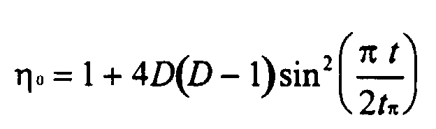
- the structure is preferably optimized as described below to maximize the light in the ⁇ 1 orders or, equivalently, to minimize the -0th order transmission,.
- the 0 th -order transmission is determined by the differential thickness t between the thick regions 33 and the thin regions 34.
- t must correspond to a phase delay of ⁇ (180°) for light propagating through fused silica relative to air.
- the ⁇ phase shift results in destructive interference for the 0th-order transmitted beam.
- the duty cycle D is advantageously within 0.39 ⁇ D ⁇ 0.61 for ⁇ o ⁇ 0.05.
- the duty cycle is the primary contributor to increased 0 th -order transmission, however it is understood that the compounding effect of imperfect etch depth variation leads to more stringent tolerances than those listed above.
- the duty cycle variation acceptable for ⁇ o ⁇ 0.05 then corresponds to a thick region width of 0.534 ⁇ m ⁇ 118nm.
- the differential thickness is 0.271 ⁇ m ⁇ 38nm.
- a linear chirp is desirable so the Bragg wavelength change is uniformly distributed along the length.
- the chirp profile along the length of the grating is nearly linear.
- the sixth step in making a fiber grating is to use the chirped phase mask to write the chirped Bragg grating in fiber.
- a chirped fiber Bragg grating can be fabricated using the chirped phase mask without deleterious modification of the fiber.
- UV photosensitive optical fiber is simply placed in the region near the phase mask where the two diffracted beams overlap, and the grating is written in the fiber by directing collimated UV light at normal incidence through the mask.
- the fiber need not be stressed, bent or tapered. It can be straight and parallel to the phase mask for high reproducibility.
- Typical fiber-to-mask distances are on the order of 200 ⁇ m and typical exposure fluences are in the range 100-400 mJ/cm 2 /pulse.
- Fig. 5 is a schematic cross section of the resulting chirped fiber Bragg grating 60 comprising a core 61 with a first index of refraction surrounded by a cladding 62 having a second (lower) index of refraction.
- the core includes a chirped grating 63 comprising a plurality of index perturbations 64 spaced along a length of the fiber.
- the grating is intrinsically continuously chirped because the phase mask was continuously chirped due to the use of a continuously curved mirror.
- Fig. 6 is a graphical illustration of the fiber Bragg grating wavelength chirp as a function of the curved mirror displacement used in making the chirped phase mask. Curves are shown for Bragg gratings at 980nm and 1480nm written in a typical fiber with an effective refractive index of 1.45.
- a Bragg grating was fabricated using 0.6cm of a phase mask chirped at 23nm/cm.
- Fig. 7 shows a typical transmission spectrum of the device. The extended dip at short wavelengths is due to coupling to radiation modes which occurs in transmission through the grating. When used in reflection, the radiation mode coupling does not occur and light is reflected only for wavelengths within the Bragg grating resonance. The spectrum has a -10dB width of 14.5nm which is in agreement with the expected width. Wider bandwidth gratings may be written either by using a larger portion of the phase mask or by increasing the mask chirp.
Abstract
Description

Claims (9)
- A method for making a continuous chirped phase mask comprising the steps of:providing a substrate of UV light transparent material, said substrate including a planar surface coated with photoresist;exposing said photoresist to the pattern of light formed by the interference of a collimated beam and a portion of said collimated beam reflected from a continuous curved mirror;developing said photoresist; andetching said substrate to produce a phase mask having a continuous chirped surface relief grating.
- Apparatus for making a continuous chirped phase mask from a substrate comprising:a source of a collimated light beam;a continuous curved mirror;a substrate mount adjacent to said curved mirror for supporting said substrate, said curved mirror and said substrate mount rotatably mounted with respect to said collimated beam, whereby the angle of incidence of said beam can be adjusted so that a first portion of said beam interferes with a second portion of said beam reflected from said mirror at the surface of said substrate disposed in said mount.
- Apparatus of claim 2 wherein said curved mirror is a flexible curved mirror whose degree of curvature can be varied.
- A continuous chirped phase mask made by the method of claim 1.
- A method for making a continuously chirped fiber Bragg grating comprising the steps of:providing a chirped phase mask having a continuous chirped surface relief grating;disposing a UV photosensitive optical fiber parallel to said phase mask; andtransmitting ultraviolet light through said phase mask to write a continuous chirped Bragg grating in said fiber.
- A continuous chirped fiber Bragg grating made by the method of claim 5.
- A continuous chirped phase mask for use with an incident beam of wavelength λ comprising:
a substrate transparent to light of wavelength λ having a surface comprising a sequence of alternating thick regions and thin regions forming a continuous chirped surface relief grating, said thick and thin regions having a differential thickness t corresponding to a phase delay of π(180°) for light of wavelength λ propagating through said substrate. - A phase mask according to claim 7 wherein said substrate is fused silica.
- A phase mask according to claim 7 wherein said continuous chirped surface relief grating is linearly chirped.
Applications Claiming Priority (2)
| Application Number | Priority Date | Filing Date | Title |
|---|---|---|---|
| US08/740,745 US5718738A (en) | 1996-11-04 | 1996-11-04 | Method for making continuously chirped fiber bragg gratings |
| US740745 | 1996-11-04 |
Publications (2)
| Publication Number | Publication Date |
|---|---|
| EP0840147A2 true EP0840147A2 (en) | 1998-05-06 |
| EP0840147A3 EP0840147A3 (en) | 1999-06-16 |
Family
ID=24977888
Family Applications (1)
| Application Number | Title | Priority Date | Filing Date |
|---|---|---|---|
| EP97308602A Withdrawn EP0840147A3 (en) | 1996-11-04 | 1997-10-28 | Method and apparatus for making continuous chirped fiber bragg gratings |
Country Status (4)
| Country | Link |
|---|---|
| US (1) | US5718738A (en) |
| EP (1) | EP0840147A3 (en) |
| JP (1) | JP3330858B2 (en) |
| AU (1) | AU739886B2 (en) |
Families Citing this family (24)
| Publication number | Priority date | Publication date | Assignee | Title |
|---|---|---|---|---|
| US6314220B1 (en) | 1995-03-13 | 2001-11-06 | Templex Technology, Inc. | Segmented complex fiber gratings |
| FR2745641B1 (en) * | 1996-03-01 | 1998-04-10 | Alcatel Submarcom | FILTER OBTAINED BY REGISTERING A BRAGG NETWORK IN AN OPTICAL FIBER |
| AUPO515297A0 (en) * | 1997-02-19 | 1997-04-11 | Future Fibre Technologies Pty Ltd | A method of providing in-situ chirped gratings in waveguides and waveguides made by that method |
| KR100294540B1 (en) | 1997-12-31 | 2001-07-12 | 윤종용 | Tunable chirped fiber gratings |
| US6522797B1 (en) | 1998-09-01 | 2003-02-18 | Input/Output, Inc. | Seismic optical acoustic recursive sensor system |
| US7065298B1 (en) | 1998-11-17 | 2006-06-20 | Intel Corporation | Code-based optical networks, methods, and apparatus |
| US6347171B1 (en) | 1999-03-31 | 2002-02-12 | Matsushita Electric Industrial Co., Ltd. | Method and apparatus for forming a diffraction grating |
| US7242464B2 (en) * | 1999-06-24 | 2007-07-10 | Asml Holdings N.V. | Method for characterizing optical systems using holographic reticles |
| US6313771B1 (en) | 1999-11-17 | 2001-11-06 | Templex Technology, Inc. | Codes, methods, and apparatus for optical encoding and decoding |
| US6961490B2 (en) * | 2000-01-27 | 2005-11-01 | Unaxis-Balzers Aktiengesellschaft | Waveguide plate and process for its production and microtitre plate |
| US6421167B1 (en) | 2000-03-03 | 2002-07-16 | General Dynamics Advanced Technology Systems, Inc. | Multiple function bandwidth management systems |
| US6356684B1 (en) | 2000-04-14 | 2002-03-12 | General Dynamics Advanced Technology Systems, Inc. | Adjustable optical fiber grating dispersion compensators |
| US6577792B2 (en) | 2001-03-15 | 2003-06-10 | 3M Innovative Properties Company | Wide-bandwidth chirped fiber Bragg gratings with low delay ripple amplitude |
| US6901188B2 (en) * | 2001-03-15 | 2005-05-31 | 3M Innovative Properties Company | Dispersion compensation modules with fiber Bragg gratings |
| US20030017421A1 (en) * | 2001-07-18 | 2003-01-23 | Miri Park | Holographic grating fabrication using mirror with surface curvature |
| US6567588B2 (en) * | 2001-08-28 | 2003-05-20 | Photronics, Inc. | Method for fabricating chirped fiber bragg gratings |
| US7043121B2 (en) * | 2001-12-06 | 2006-05-09 | Zygo Corporation | Method and apparatus for writing apodized patterns |
| US20030121289A1 (en) * | 2002-01-02 | 2003-07-03 | Benda John A. | Long period fiber Bragg gratings written with alternate side IR laser illumination |
| JP4824273B2 (en) * | 2003-11-07 | 2011-11-30 | 大日本印刷株式会社 | Diffraction grating phase mask |
| JP5360399B2 (en) * | 2009-08-06 | 2013-12-04 | 大日本印刷株式会社 | Diffraction grating phase mask |
| US8817269B2 (en) | 2011-04-26 | 2014-08-26 | Carl Zeiss Meditec, Inc. | Fizeau reference arm using a chirped fiber bragg grating |
| CN102998740B (en) * | 2012-11-30 | 2014-04-16 | 燕山大学 | Device and method for simultaneously inscribing multi-wavelength array gratings in ribbon fiber |
| CN106918866B (en) * | 2017-05-10 | 2023-08-18 | 深圳大学 | Optical fiber Bragg chirp phase shift grating and manufacturing method and equipment thereof |
| CN107340565B (en) * | 2017-08-25 | 2018-10-09 | 武汉理工大学 | A kind of online device and method for preparing optical fiber optical grating array and automatically switching wavelength |
Citations (4)
| Publication number | Priority date | Publication date | Assignee | Title |
|---|---|---|---|---|
| EP0604039A2 (en) * | 1992-12-23 | 1994-06-29 | AT&T Corp. | Method for forming spatially-varying distributed bragg reflectors in optical media |
| US5367588A (en) * | 1992-10-29 | 1994-11-22 | Her Majesty The Queen In Right Of Canada, As Represented By The Minister Of Communications | Method of fabricating Bragg gratings using a silica glass phase grating mask and mask used by same |
| JPH08101322A (en) * | 1994-09-30 | 1996-04-16 | Nippon Telegr & Teleph Corp <Ntt> | Production of transmission type fiber grating filter and apparatus therefor |
| JPH08286009A (en) * | 1995-04-13 | 1996-11-01 | Sumitomo Electric Ind Ltd | Device for forming chirp grating |
Family Cites Families (4)
| Publication number | Priority date | Publication date | Assignee | Title |
|---|---|---|---|---|
| US3676914A (en) * | 1970-05-01 | 1972-07-18 | Zenith Radio Corp | Manufacture of shadow mask color picture tube |
| US5116461A (en) * | 1991-04-22 | 1992-05-26 | Motorola, Inc. | Method for fabricating an angled diffraction grating |
| US5363329A (en) * | 1993-11-10 | 1994-11-08 | Eugeniy Troyan | Semiconductor memory device for use in an electrically alterable read-only memory |
| US5620495A (en) * | 1995-08-16 | 1997-04-15 | Lucent Technologies Inc. | Formation of gratings in polymer-coated optical fibers |
-
1996
- 1996-11-04 US US08/740,745 patent/US5718738A/en not_active Expired - Lifetime
-
1997
- 1997-10-16 JP JP28327697A patent/JP3330858B2/en not_active Expired - Fee Related
- 1997-10-28 EP EP97308602A patent/EP0840147A3/en not_active Withdrawn
- 1997-10-29 AU AU43634/97A patent/AU739886B2/en not_active Ceased
Patent Citations (4)
| Publication number | Priority date | Publication date | Assignee | Title |
|---|---|---|---|---|
| US5367588A (en) * | 1992-10-29 | 1994-11-22 | Her Majesty The Queen In Right Of Canada, As Represented By The Minister Of Communications | Method of fabricating Bragg gratings using a silica glass phase grating mask and mask used by same |
| EP0604039A2 (en) * | 1992-12-23 | 1994-06-29 | AT&T Corp. | Method for forming spatially-varying distributed bragg reflectors in optical media |
| JPH08101322A (en) * | 1994-09-30 | 1996-04-16 | Nippon Telegr & Teleph Corp <Ntt> | Production of transmission type fiber grating filter and apparatus therefor |
| JPH08286009A (en) * | 1995-04-13 | 1996-11-01 | Sumitomo Electric Ind Ltd | Device for forming chirp grating |
Non-Patent Citations (3)
| Title |
|---|
| KASHYAP R ET AL: "DEMONSTRATION OF DISPERSION COMPENSATION IN ALL-FIBRE PHOTOINDUCED CHIRPED GRATINGS" PURE AND APPLIED OPTICS, vol. 4, 1995, pages 425-429, XP000619131 * |
| PATENT ABSTRACTS OF JAPAN vol. 096, no. 008, 30 August 1996 & JP 08 101322 A (NIPPON TELEGR &TELEPH CORP <NTT>), 16 April 1996 * |
| PATENT ABSTRACTS OF JAPAN vol. 097, no. 003, 31 March 1997 & JP 08 286009 A (SUMITOMO ELECTRIC IND LTD), 1 November 1996 * |
Also Published As
| Publication number | Publication date |
|---|---|
| US5718738A (en) | 1998-02-17 |
| JP3330858B2 (en) | 2002-09-30 |
| JPH10142413A (en) | 1998-05-29 |
| AU739886B2 (en) | 2001-10-25 |
| EP0840147A3 (en) | 1999-06-16 |
| AU4363497A (en) | 1998-05-07 |
Similar Documents
| Publication | Publication Date | Title |
|---|---|---|
| US5718738A (en) | Method for making continuously chirped fiber bragg gratings | |
| EP0960347B1 (en) | Phase mask with spatially variable diffraction efficiency | |
| JPH09508713A (en) | Light grating | |
| CA2307371A1 (en) | Long-length continuous phase bragg reflectors in optical media | |
| AU7549791A (en) | A method of forming a refractive index grating in an optical waveguide | |
| US6728444B2 (en) | Fabrication of chirped fiber bragg gratings of any desired bandwidth using frequency modulation | |
| WO2000011509A1 (en) | Apparatus for manufacturing long-period fiber gratings and apparatus for manufacturing two-band long-period fiber gratings using the same | |
| US6574395B1 (en) | Photowritten Bragg grating apodization method | |
| US5953471A (en) | Optical communication system having short period reflective Bragg gratings | |
| US6170297B1 (en) | Jig for manufacturing long period grating filter and apparatus and method for manufacturing long period grating filter using the same | |
| US5708739A (en) | Method and apparatus for photobleaching patterns in irradiated optical waveguides | |
| CA2215662A1 (en) | Method of writing photosensitive grating using lloyd's mirror | |
| KR20000060201A (en) | Temperature-compensated long period optical fiber grating filter | |
| US6275631B1 (en) | Apparatus for manufacturing long-period optical fiber grating | |
| JP3693494B2 (en) | Chirped optical fiber filter manufacturing method and chirped optical fiber filter | |
| JP2830819B2 (en) | Optical device having low reflection grating and method of manufacturing low reflection grating | |
| US6766080B2 (en) | Optical waveguide type defraction grating device and a method of manufacturing thereof | |
| JP2985820B2 (en) | Optical waveguide having low reflection grating and method of manufacturing the same | |
| JP4543128B2 (en) | Manufacturing method and manufacturing apparatus for optical waveguide Bragg grating | |
| CA2184453C (en) | Optical device formed with grating therein, add/drop filter using same, and method of fabricating same | |
| JP3431048B2 (en) | Optical waveguide, waveguide member thereof, and manufacturing method thereof | |
| JPH09304638A (en) | Optical waveguide grating and its production | |
| CA2281787C (en) | Phase mask with spatially variable diffraction efficiency | |
| AU2002301376B2 (en) | Apparatus for manufacturing two-band long-period fiber gratings using the same | |
| JP2006099011A5 (en) |
Legal Events
| Date | Code | Title | Description |
|---|---|---|---|
| PUAI | Public reference made under article 153(3) epc to a published international application that has entered the european phase |
Free format text: ORIGINAL CODE: 0009012 |
|
| AK | Designated contracting states |
Kind code of ref document: A2 Designated state(s): DE FR GB |
|
| AX | Request for extension of the european patent |
Free format text: AL;LT;LV;RO;SI |
|
| PUAL | Search report despatched |
Free format text: ORIGINAL CODE: 0009013 |
|
| RIC1 | Information provided on ipc code assigned before grant |
Free format text: 6G 02B 6/16 A, 6G 03F 7/00 B |
|
| AK | Designated contracting states |
Kind code of ref document: A3 Designated state(s): AT BE CH DE DK ES FI FR GB GR IE IT LI LU MC NL PT SE |
|
| AX | Request for extension of the european patent |
Free format text: AL;LT;LV;RO;SI |
|
| 17P | Request for examination filed |
Effective date: 19991201 |
|
| AKX | Designation fees paid |
Free format text: DE FR GB |
|
| 17Q | First examination report despatched |
Effective date: 20000306 |
|
| APBT | Appeal procedure closed |
Free format text: ORIGINAL CODE: EPIDOSNNOA9E |
|
| APAF | Appeal reference modified |
Free format text: ORIGINAL CODE: EPIDOSCREFNE |
|
| GRAP | Despatch of communication of intention to grant a patent |
Free format text: ORIGINAL CODE: EPIDOSNIGR1 |
|
| RIC1 | Information provided on ipc code assigned before grant |
Ipc: G03F 7/00 20060101ALI20061109BHEP Ipc: G02B 6/02 20060101AFI20061109BHEP |
|
| GRAS | Grant fee paid |
Free format text: ORIGINAL CODE: EPIDOSNIGR3 |
|
| STAA | Information on the status of an ep patent application or granted ep patent |
Free format text: STATUS: THE APPLICATION IS DEEMED TO BE WITHDRAWN |
|
| RAP3 | Party data changed (applicant data changed or rights of an application transferred) |
Owner name: LUCENT TECHNOLOGIES INC. |
|
| 18D | Application deemed to be withdrawn |
Effective date: 20090501 |