EP0836518B1 - A portable, personal breathing apparatus - Google Patents
A portable, personal breathing apparatus Download PDFInfo
- Publication number
- EP0836518B1 EP0836518B1 EP96918299A EP96918299A EP0836518B1 EP 0836518 B1 EP0836518 B1 EP 0836518B1 EP 96918299 A EP96918299 A EP 96918299A EP 96918299 A EP96918299 A EP 96918299A EP 0836518 B1 EP0836518 B1 EP 0836518B1
- Authority
- EP
- European Patent Office
- Prior art keywords
- main body
- inner member
- respect
- slots
- user
- Prior art date
- Legal status (The legal status is an assumption and is not a legal conclusion. Google has not performed a legal analysis and makes no representation as to the accuracy of the status listed.)
- Expired - Lifetime
Links
- 230000029058 respiratory gaseous exchange Effects 0.000 title claims abstract description 29
- 210000004072 lung Anatomy 0.000 claims abstract description 51
- 230000000694 effects Effects 0.000 claims description 11
- 238000004891 communication Methods 0.000 claims description 4
- 230000013011 mating Effects 0.000 claims description 4
- 238000000034 method Methods 0.000 abstract description 3
- 238000009527 percussion Methods 0.000 description 21
- 230000000241 respiratory effect Effects 0.000 description 13
- QVGXLLKOCUKJST-UHFFFAOYSA-N atomic oxygen Chemical compound [O] QVGXLLKOCUKJST-UHFFFAOYSA-N 0.000 description 8
- 229910052760 oxygen Inorganic materials 0.000 description 8
- 239000001301 oxygen Substances 0.000 description 8
- CURLTUGMZLYLDI-UHFFFAOYSA-N Carbon dioxide Chemical compound O=C=O CURLTUGMZLYLDI-UHFFFAOYSA-N 0.000 description 5
- 210000002445 nipple Anatomy 0.000 description 5
- 230000002685 pulmonary effect Effects 0.000 description 4
- 235000014676 Phragmites communis Nutrition 0.000 description 3
- 229910002092 carbon dioxide Inorganic materials 0.000 description 3
- 210000004081 cilia Anatomy 0.000 description 3
- 230000002459 sustained effect Effects 0.000 description 3
- 210000001519 tissue Anatomy 0.000 description 3
- 206010003598 Atelectasis Diseases 0.000 description 2
- 206010014561 Emphysema Diseases 0.000 description 2
- 208000007123 Pulmonary Atelectasis Diseases 0.000 description 2
- 239000001569 carbon dioxide Substances 0.000 description 2
- 230000006835 compression Effects 0.000 description 2
- 238000007906 compression Methods 0.000 description 2
- 230000002035 prolonged effect Effects 0.000 description 2
- 238000005086 pumping Methods 0.000 description 2
- RZVAJINKPMORJF-UHFFFAOYSA-N Acetaminophen Chemical class CC(=O)NC1=CC=C(O)C=C1 RZVAJINKPMORJF-UHFFFAOYSA-N 0.000 description 1
- 206010006458 Bronchitis chronic Diseases 0.000 description 1
- JSMRMEYFZHIPJV-UHFFFAOYSA-N C1C2CCC1C2 Chemical compound C1C2CCC1C2 JSMRMEYFZHIPJV-UHFFFAOYSA-N 0.000 description 1
- 0 CCCI1=CS*C1 Chemical compound CCCI1=CS*C1 0.000 description 1
- 208000006545 Chronic Obstructive Pulmonary Disease Diseases 0.000 description 1
- 239000004677 Nylon Substances 0.000 description 1
- 241001526284 Percus <genus> Species 0.000 description 1
- 206010035664 Pneumonia Diseases 0.000 description 1
- 239000004698 Polyethylene Substances 0.000 description 1
- 206010036790 Productive cough Diseases 0.000 description 1
- 230000003187 abdominal effect Effects 0.000 description 1
- 210000003489 abdominal muscle Anatomy 0.000 description 1
- 238000012084 abdominal surgery Methods 0.000 description 1
- 238000010521 absorption reaction Methods 0.000 description 1
- 208000006673 asthma Diseases 0.000 description 1
- 210000004556 brain Anatomy 0.000 description 1
- 210000000621 bronchi Anatomy 0.000 description 1
- 206010006451 bronchitis Diseases 0.000 description 1
- 208000007451 chronic bronchitis Diseases 0.000 description 1
- 230000001419 dependent effect Effects 0.000 description 1
- 230000029087 digestion Effects 0.000 description 1
- 210000003811 finger Anatomy 0.000 description 1
- 235000013305 food Nutrition 0.000 description 1
- 238000004519 manufacturing process Methods 0.000 description 1
- 230000001483 mobilizing effect Effects 0.000 description 1
- 210000003205 muscle Anatomy 0.000 description 1
- 230000003387 muscular Effects 0.000 description 1
- 230000017074 necrotic cell death Effects 0.000 description 1
- 229920001778 nylon Polymers 0.000 description 1
- 230000010355 oscillation Effects 0.000 description 1
- 230000003534 oscillatory effect Effects 0.000 description 1
- 239000004033 plastic Substances 0.000 description 1
- 229920003023 plastic Polymers 0.000 description 1
- 239000004417 polycarbonate Substances 0.000 description 1
- 229920000515 polycarbonate Polymers 0.000 description 1
- -1 polyethylene Polymers 0.000 description 1
- 229920000573 polyethylene Polymers 0.000 description 1
- 238000011084 recovery Methods 0.000 description 1
- 230000002441 reversible effect Effects 0.000 description 1
- 230000028327 secretion Effects 0.000 description 1
- 238000005728 strengthening Methods 0.000 description 1
- 210000003813 thumb Anatomy 0.000 description 1
Images

Classifications
-
- A—HUMAN NECESSITIES
- A63—SPORTS; GAMES; AMUSEMENTS
- A63B—APPARATUS FOR PHYSICAL TRAINING, GYMNASTICS, SWIMMING, CLIMBING, OR FENCING; BALL GAMES; TRAINING EQUIPMENT
- A63B23/00—Exercising apparatus specially adapted for particular parts of the body
- A63B23/18—Exercising apparatus specially adapted for particular parts of the body for improving respiratory function
-
- A—HUMAN NECESSITIES
- A61—MEDICAL OR VETERINARY SCIENCE; HYGIENE
- A61M—DEVICES FOR INTRODUCING MEDIA INTO, OR ONTO, THE BODY; DEVICES FOR TRANSDUCING BODY MEDIA OR FOR TAKING MEDIA FROM THE BODY; DEVICES FOR PRODUCING OR ENDING SLEEP OR STUPOR
- A61M16/00—Devices for influencing the respiratory system of patients by gas treatment, e.g. mouth-to-mouth respiration; Tracheal tubes
- A61M16/0003—Accessories therefor, e.g. sensors, vibrators, negative pressure
- A61M16/0006—Accessories therefor, e.g. sensors, vibrators, negative pressure with means for creating vibrations in patients' airways
Definitions
- the present invention relates to a portable respiratory exercise apparatus providing resistance and intra-trachea bronchial percussion on inspiration and expiration to increase pulmonary efficiency, while improving cilial movement which assists mobilization of intrabronchial mucous or secretions within the lungs.
- Forcible and prolonged inspiration and expiration causes a greater expansion and collapse of the air vesicles (alveoli), especially those deep in the lung tissue.
- alveoli air vesicles
- pulmonary muscles are strengthened and developed, thereby allowing a freer and greater exchange of oxygen and carbon dioxide.
- Persons suffering from lung ailments, healthy persons, and athletes can all improve their pulmonary efficiency through forcible and prolonged inspiration and expiration against resistance.
- Some people are able to take only shallow breaths because they are suffering from lung ailments such as asthma, emphysema, chronic bronchitis, chronic obstructive pulmonary disease, or other ailments which reduce the oxygen/CO 2 exchange.
- lung ailments such as asthma, emphysema, chronic bronchitis, chronic obstructive pulmonary disease, or other ailments which reduce the oxygen/CO 2 exchange.
- patients recovering from abdominal surgery experience pain during deep breathing and may therefore restrict their own breathing to shallow breaths. In both of the above situations, recovery is slowed because the patients suffer from reduced exchange of oxygen and carbon dioxide in the tissue.
- the patients are at risk of developing atelectasis because their lungs are not being fully expanded. Atelectasis is a partial collapse of the lungs, possibly leading to necrosis of the lung alveoli. This exacerbates any ailments from which the patient may be suffering by causing poor oxygen exchange in the lungs and possibly resulting in pneumonia.
- Known respiratory exercisers utilize a ball inside a large tube. A user exhales or inhales through a smaller attached tube, causing the ball to rise proportionally to the rate of airflow.
- these known respiratory exercisers only provide resistance to inspiration or expiration, but not both. Further, the large tube must be maintained in a vertical position in order for the respiratory exerciser to operate correctly. This is inconvenient for persons suffering from lung ailments who may be confined to bed and for athletes who wish to restrict respiratory volume flow during exercise. Still further, this respiratory exerciser does not provide a percussive effect on the user; i.e., a vibration of the air on inspiration or expiration.
- Another known respiratory exerciser provides a mask which allows air to be inhaled freely and provides resistance against the expiration of air.
- the masks do not provide resistance to inspiration and do not provide vibration. Further, the masks are too large to be conveniently portable.
- Another respiratory exerciser provides a vibration effect upon expiration.
- a patient exhales into a tube connected to a conical element loosely supporting a ball.
- the ball is displaced from the conical element causing an oscillatory movement of the ball, thereby generating a variable pressure opposing the expiration.
- This device does not provide vibration of air during inspiration. It is inconvenient for some patients because it must be maintained at a horizontal position during use. Further, the device provides only varying oscillations in air pressure, rather than a sharp percussion of the air by rapid bursts of air pressure from complete opening and closure of the air passages.
- Another respira-tory exerciser provides a vibration effect upon either inspiration or expiration by using a pair of adjacent air passageways each containing a reed.
- Each passageway contains a valve utilizing a coil spring to allow either inspiration or expiration.
- the compression of each spring can be adjusted to vary the resistance to inspiration and expiration independently.
- air flowing past each reed causes each reed to rapidly vibrate, causing a vibration effect on the lungs of the patient.
- adjustment of the coil spring compression during inspiration and expiration is not convenient. Further, vibration of the air is not as effective as would be a sharp percussion of the air by rapid, complete opening and closure of the air passages.
- FR-A-2 379 291 discloses a lung exercising device comprising an outer member, an inner member reciprocally and rotatably mounted with the outer member, a mouthpiece in communication with the inner member, at least are opening in the under and outer members adapted to be in selective communication to device an air passage extending from the mouth piece through the inner member and out of the outer member.
- the present invention provides a respiratory exercise apparatus which is portable, non-positional, and provides percussion and resistance during inspiration and expiration and pulsing during expiration.
- the user can select whether to exercise through resistance, percussion, or pulsing.
- the breathing apparatus has a main body and a movable inner member, which in the preferred embodiment is an inner cylinder.
- both the main body and the inner cylinder have holes and slots for resistance, pulse, and percussion exercises. By rotating the inner cylinder and locking it in place, the desired method of exercise can be selected and performed.
- Resistance exercises can be performed by aligning holes in the main body and the inner cylinder. Alignment and locking are accomplished through use of grooves and a locking pin, screw, boss, etc.
- the inner cylinder has a plurality of grooves with the grooves being preferably oblong and adapted to receive the locking pin to restrict movement.
- the oblong grooves allow limited reciprocal movement of the inner cylinder with respect to the main body and prevent rotational movement. This restricted movement allows mating holes to move with respect to one another and automatically vary the resistance as a user inhales and exhales.
- the inner cylinder can be manually reciprocated to vary the resistance or held in place to maintain a predetermined resistance.
- there is a flange that has indicator holes that facilitate easy alignment.
- a further resistance exercise can be performed by holding the breathing apparatus generally vertically with the inner cylinder pointing up and exhaling. This will raise the inner cylinder. When the lungs are empty, the inner cylinder automatically drops back into the main body. The user then tries to raise the inner cylinder again by exhaling any remaining air in the lungs. The device is then held with the inner cylinder down, which causes the inner cylinder to automatically drop down. The user then inhales to pull the inner cylinder back into the main body until the lungs are full, which then causes the inner cylinder to drop back down. The exercise is completed by further inhaling to try to raise the inner cylinder.
- Percussion exercises can be performed by locking the locking member in a second set of grooves which will align slots in the main body and the inner cylinder.
- this groove is formed about the circumference of the inner cylinder to allow limited rotational movement of the inner cylinder with respect to the main body.
- the user can percuss the lungs by rapidly rotating the inner cylinder while the user inhales and exhales into the main body. Rotation of the inner cylinder moves the slots in the inner cylinder and main body with respect to one another allowing quick bursts of air to enter and exit the users lungs.
- This provides a strong percussion effect which expands the air vesicles deep in the lungs and loosens mucous blockages in the lungs. Because the present invention provides rapid intermittent complete closure of the airflow in and out of the user's lungs during percussion, a more effective percussion effect is obtained than by merely vibrating the air pressure.
- Pulse exercises are performed by aligning the locking device with a longitudinally extending groove. This allows the inner cylinder to reciprocate sufficiently to expose the inner slots. To perform the exercise, the device is held upright, and the user exhales, which causes the inner cylinder to raise, expose the slots, and drop repeatedly. In the preferred embodiment, the inner cylinder is weighted to facilitate the reciprocating action.
- the respiratory exercise apparatus includes a generally cylindrical main body having at least one main aperture. Although disclosed as cylindrical, in some embodiments, the main body can be non-cylindrical. An inner cylinder is disposed within the main body and can rotate and reciprocate within the main body.
- the breathing apparatus of the present invention is generally shown at 10.
- the breathing apparatus includes a main body 12 and an inner member 14, which is preferably a cylindrical tube.
- the main body 12 is also illustrated as a cylindrical tube, but it should be understood that the shape of the main body 12 could be any desired shape.
- the inner member 14 could be any desired shape which would allow reciprocal movement with respect to the main body 12.
- the main body 12 has a mouthpiece 16 attached to a flange 18.
- the flange 18 is preferably angled at about 45° and includes a bore 20 that communicates with the interior 22 of the main body 12.
- the mouthpiece 16 is sufficiently flexible to be stretched over flange 18 to change the angle of the mouthpiece from 45° to generally in line with the main body 12.
- the opposite end 24 of the main body 12 is open for receipt of the inner cylinder 14.
- the inner cylinder 14 has a closed end 26 and an open end 28 with the open end 28 being inserted into main body 12.
- a knob 30 extends from the end 26 so that the inner cylinder 14 can be manually rotated or reciprocated within the main body 12.
- the main body is 90.602 mm (3.567") long, which includes the mouthpiece 16, and the inner cylinder is 93.218 mm (3.67") if the knob 30 is included.
- the main body and inner cylinder are made of polycarbonate or other moldable plastic, such as polyethylene.
- the breathing apparatus 10 is adapted for exercising a users lungs through inspiration and expiration against resistance pulsing and percussion.
- the apparatus 10 has two sets of openings that can be aligned to provide resistance, pulsing or percussion exercises. By rotating the inner cylinder 14 with respect to the main body 12, the different sets of openings can be aligned and locked in position to allow for a selected exercise.
- the main body 12 has a hole 32 and a pair of elongated openings or slots 34 and 38 which are about 180° apart.
- the inner cylinder 14 has a plurality of paired holes 42 and 43 and elongated openings or slots 44 which extend through the inner cylinder 14. These holes 42 and 43 and slots 44 are positioned to align with the holes 32 and elongated slots 34 and 38 respectively as the inner cylinder 14 is rotated with respect to the main body 12. When the holes 42 and 43 are aligned with the hole 32, resistance exercises can be performed.
- a set of grooves 46 which correspond to the holes 42 are provided in the inner cylinder for holding the inner cylinder 14 with respect to the main body 12. Grooves 46 are adapted to receive a locking member 50 to lock the cylinder in position once an appropriate hole 42 is aligned with hole 32.
- the slots 34, 38, and 44 are aligned.
- a different set of grooves 48 are provided, which correspond to the slots 44. Grooves 48 extend circumferentially about the cylinder to restrict movement of the cylinder 14 and main body 12 so that only the slots are aligned for percussive exercises. As will be further described below, the grooves 48 permit limited rotational movement of cylinder 14 with respect to main body 12.
- the locking member When pulsing is desired, the locking member is inserted into a longitudinally extending groove 49, which extends along the inner cylinder. This groove allows the inner cylinder 14 to reciprocate with respect to the main body 12.
- the locking member 50 is a small bolt that is threaded into a threaded bore.
- a raised portion 51 prevents the member 50 from being threaded too far into the grooves.
- the bolt can be screwed into the groove as desired. It should be understood that other types of locking members could be used, such as a spring loaded detent, a fixed detent, etc.
- the grooves 46 which correspond to the holes 32 and 42, are preferably oblong and have their longitudinal axis extending parallel to the longitudinal axis of the inner cylinder 14.
- the locking member 50 has a diameter that is less than the length and width of the groove 46 so that the inner cylinder can reciprocate slightly within the main body 12. Due to the movement of the inner cylinder 14 with respect to the main body 12, the resistance against exhaling can be increased; i.e., the ability to exhale is further restricted, due to the shifting from the hole 43 to the hole 43. When the user inhales, the inner cylinder 14 is pulled back into the main body 12 to shift from hole 43 to hole 42, reducing resistance upon inhalation.
- the hole sets 42 and 43 have different diameters to provide varied resistance, depending upon whether the user is exhaling or inhaling.
- the diameters of the holes 42 are 4.75 mm (.187"), 3.96 mm (.156"), 3.18 mm (.125”) and 2.36 mm (.093”);
- the diameters of holes 43 are 2.77 mm (.109”), 2.36 mm (.093”); 1.98 mm (.078”), and 1.57 mm (.062"); and the diameter of the hole 32 is 4.75 mm (.187").
- Alignment holes 26 are provided in flange 27. These holes 26 correspond in size to their corresponding holes. By locating the holes with the locking member 50, the desired holes 42 and 43 are aligned. Alternatively, by aligning the desired diameter hole 42 with the hole 32, the locking member 50 can be inserted into the adjacent groove.
- the holes 42 and 43 are separated into two groups with each set about 180° apart and the hole sets in each group are about 30° apart.
- the grooves 46 are also separated into two sets with each set about 180° apart and the grooves in each set being about 30° apart.
- the hole sets 42 and 43 and the grooves 46 are about 90° apart.
- Percussion is dependent upon grooves 48 which extend between the grooves 46 and correspond to the alignment of the inner slots 44 and the outer slots 34.
- each groove 48 extends circumferentially about the inner cylinder through an arc which is greater than 90°.
- the inner cylinder 14 can be rotated with respect to the main body 12 through an arc defined by the groove; i.e., approximately 90°.
- the slots 44 sweep by the slots 34 to rapidly open and close the slots and rapidly block and open the ingress and egress of air into and out of the breathing apparatus 10. This rapid action causes a percussive result in the users lungs. It should be appreciated by those of ordinary skill in the art that this invention permits percussive exercising of the lungs on inhalation and exhalation.
- the grooves 48 are positioned apart by about 180°. Each groove is adjacent the end of the slots 44 and extends circumferentially beyond the slots a slight distance to enhance the percussive effect the user receives upon use. Preferably, there are two sets of slots 44 and two grooves 48. Only one set of slots 44 and grooves 48 are shown. Additionally, there are preferably two sets of slots 34 on opposed sides of main body 12. The groove 48 opposite the aligned slot 44 is the groove that receives the locking member 50. It should be appreciated that the groove 48 adjacent the slot 44 could be used if the locking member or the slot 34 were repositioned during manufacture.
- the slots 34 and 44 are long and narrow to give increased percussive effect to the user.
- the disclosed slots 34 and 44 are approximately 50.8 mm (two (2)) inches long and 1.57 mm (.062) inches wide.
- each of the slots 34 and 44 can be formed by two smaller slots positioned end to end.
- Applicant has found that long narrow slots provide a more effective percussion of the lungs because greater volumes of air can rapidly pass through the slots, and the slots can be closed rapidly, resulting in bursts of air into the lungs. Because of the burst of air, a humming noise is produced, which can also act as an incentive for increased usage.
- a notch 49 is provided to permit easier alignment of the slots 34 and 44. By aligning notch 49 with locking member 50, the slots are automatically aligned.
- the groove 49 is aligned with locking member 50.
- a smaller notch 51 is provided to facilitate proper alignment.
- groove 49 is directly beneath locking member 50 and can then receive locking member 50.
- Groove 49 allows the inner cylinder to reciprocate with respect to the main body 12 as the user exhales. With the unit pointed up, the user exhales and the inner cylinder is raised to expose slots 44. When slots 44 are exposed, the inner cylinder 14 drops down momentarily until pressure from the exhaled air increases in the cylinder 14 to raise it again. This repeated raising and dropping causes a pulsing effect on the lungs.
- the inner cylinder 14 is rotated with respect to the main body 12 to align either the holes 32 and 42 or the slots 34 and 44 or the groove 49. If resistance exercising is desired, then the holes are aligned. If percussion is desired, then the slots are aligned. If pulsing is desired, then groove 49 is aligned. Once aligned, the locking member 50 is threaded into the adjacent groove. Once the desired exercise is selected, the user inhales and exhales into the mouthpiece 16. If resistive exercising is selected, the inner cylinder 14 reciprocates within the main body 12 to automatically adjust the resistance, or the user can manually control the relative resistance by controlling the amount of reciprocal movement of the inner cylinder 14. If percussion is selected, the inner cylinder 14 is manually rotated by the user as the user inhales and exhales. Knob 30 facilitates rotation of inner cylinder 14 with respect to main body 12. If pulsing is desired, the user uses groove 49.
- a weight 60 is positioned in the inner cylinder 14.
- the weight is illustrated as a rod, but it could be a ball, a disk attached to the flange 27, a spring, etc.
- the weight 60 facilitates the reciprocal movement of the inner cylinder 14 with respect to the main body 12.
- the weight 60 forces cylinder 14 out of the main body 12 to further restrict inhalation and exhalation or with pulsing to force cylinder 14 back into the main body 12.
- a further embodiment of the present invention is illustrated generally at 66.
- the main body is about 101.6 mm (4 inches) long and 31.25 mm (1.25 inches) in diameter; the inner member 14 is sized to fit into the main body 12.
- breathing device 66 provides for additional exercises as well as the exercises that can performed with the previously described breathing device 10.
- the inner member 14 has been modified and covers are provided to allow for the additional exercises.
- the mouthpiece 16 is mounted to a short nipple 62 that extends out of the main body 12 at about a 90° angle to the longitudinal centerline 64 of main body 12.
- the nipple 62 is a 22.23 mm (7/8 inch) diameter protrusion with a 19.05 mm (3/4 inch) inside diameter.
- the orientation of mouthpiece 16 at a 90° angle allows the user of the breathing apparatus to twist the mouthpiece 16 on nipple 62 to perform various exercises which will be described more fully below and to vary the resistance when performing these exercises.
- inner member 14 of device 66 is inserted into the end of main body 12 so that it can be reciprocated and rotated with respect to main body 12.
- a knob 30 extends from the end of inner member 14 to rotate and reciprocate the inner member 14.
- breathing device 66 In addition to the previously described exercises of resistance, pulsing or bouncing and percussion; breathing device 66 also permits a pumping mode and a slow sustained maximal expiration and inspiration mode. It also includes a spring 69 to enhance the movement of the inner member 14 in the pulsing or bouncing mode. To simplify the description, the same reference numbers will be used to identify the same features found in the previous embodiment. Unless otherwise indicated, the same functions are associated with the same elements. As before, resistance exercises are provided by aligning the thumb screw with grooves 46, of which there are three in this device, with one being out of view. With screw 50 in groove 46 hole sets 42 and 43 are aligned with opening 32 (which is also not illustrated in this figure but is illustrated in figure 1).
- each pair of holes 42 and 43 are of different diameter.
- the grooves 46, or which there are three, are approximately 15.88 mm (5/8 inches) in length.
- the location grooves 46 align corresponding hole sets 42 and 43 with the exhaust opening 32.
- exhaust hole 32 is about 6.35 mm (1/4 inch) in diameter.
- Percussion exercises are performed by aligning slots 44 with slots 34.
- the slots 34 are in two pairs, 180° apart and are 1.59 mm (1/16 inch) wide by 12.7 mm (1/2 inch) long.
- a groove 48 is provided in the inner member 14 to accept the thumbscrew 50. Groove 48 is also not shown in this embodiment, since it is out of view; however, it is shown in figure 1.
- the thumbscrew 50 is inserted into groove 49.
- the inner cylinder 14 reciprocates with respect to the main body 12.
- a spring 69 is mounted in the groove 49.
- the thumbscrew 50 when inserted into groove 49 engages one end of the spring and acts against the spring to bias movement of the inner member 14. In this operation mode, the slots 34 and opening 32 in the main body are covered to prevent air from escaping through them.
- the slots 34 and opening 32 are preferably covered by the inner member 14.
- other methods of covering the openings could be used, such as for example a flexible sleeve 68 that can be snapped over the body member 12. This sleeve 68 can be rotated to close or open slots 34 and opening 32 by aligning the slot 70 and opening 71 of the sleeve 68 over the slots 44 and opening 32.
- the main body could be made without the opening 32 and lots 34.
- the user exhales and the inner member 14 slides away from main body 12 and compresses the spring 69.
- the spring provides resistance to the outward movement of the inner member 14.
- air exhaled by the user escapes through the exposed openings 44 and the inner member 14 snaps back into the main body 12 due to the bias of the spring 69 and the weight 60.
- the weight is about 12.7 mm (1//2 inch) in diameter by 38.1 mm (1 1/2 inches) in length.
- movement of the inner member 14 in and out of body 12 occurs very rapidly providing a bounce or pulse action.
- the snap back action rapidly closes and opens the air passages in the device 66 interrupting the flow of air creating resistance.
- This pulsing or bouncing action causes a very pronounced change in pressure in the lungs loosening mucous and strengthening the lungs.
- the user inhales deeply and then exhales into the mouthpiece 16 completely until all bouncing movement stops. The user then inhales deeply and repeats the exercise.
- the air passage created by openings 42, 43 and 32 remains open.
- the resistance automatically changes so that the proper resistance is selected to completely fill or empty the lungs.
- the user can exhale into the mouthpiece and raise the inner member 14.
- the inner member 14 will remain raised.
- the inner member will drop back into the body member 16.
- the resistance can be varied by turning the mouthpiece 16 at a different angle on the nipple 62 and by selecting one of the other grooves 46. By angling the mouthpiece 16, the main body 12 and inner member 14 are angled with respect to the vertical which reduces resistance.
- the breathing device 66 By rotating the breathing device 66 180° the inner member 14 points downwardly, see figure 6. The user can then inhale completely so that the inner cylinder 14 snaps up into the main body 12. When the lungs are completely filled, the main body 12 will drop down due to the weight 60 pulling the inner member 14 down. Again, by angling the mouthpiece 16, the resistance can be varied. In this mode the user experiences slow sustained maximal inspiration.
- the other exercise that can be used is the pump mode.
- an internal cover 74 is used to partially cover slots 44 which are adjacent closed end 26 and cover 68 is used to cover slot 34 and opening 32.
- the breathing device 66 is turned so that main body 12 is generally horizontal.
- the thumbscrew 50 is inserted into groove 49 or an additional groove 47 could be used, as illustrated in figure 7.
- the user can then reciprocate the inner member 14 with respect to the body member 12 as the user inhales and exhales, see arrow 45 in figure 7.
- the mouthpiece 16 is twisted on the nipple 62.
- the user inhales completely while quickly moving the inner member 14 in and out of the main body 12.
- the same is done while the user exhales completely.
- This mode very effectively maximizes air pressure changes created by the pumping action.
- This mode provides an effect similar to that achieved in the percussion mode.
- flow meters or progress meters are illustrated to indicate the amount of air flow and progress a user is making using the breathing devices of the present invention.
- the flow meter 76 attaches onto the end of the main body 12 at the thumbscrew 50.
- the thumbscrew can be used to hold the meter 76 in position.
- flowmeter 76 flexes slightly to allow the inner cylinder 14 to move along the notches 78.
- the edge of the meter 76 has a plurality of notches 78 with cam surfaces 80.
- the inner member 14 engages the cam surfaces 80 as it slides out of the main body 12 and gently forces meter 76 back to allow the flange 27 to pass.
- the notches 78 are calibrated to indicate the air flow through the breathing device 66.
- the inner member would be rotated to a groove, such as groove 72 and the slots 34 and opening 32 would be opened by cover 68 to insure that inner member 14 is not blown out of main body 12.
- the calibration would take into account the flow lost through the open passages.
- a further embodiment of a flow meter is shown generally at 82.
- a guide 84 see figure 9a, is snapped onto the main body 12 with an indicator rod 86 engaging the flange 27.
- the rod 86 is L-shaped to hook onto flange 27 and includes graduations to indicate the amount of flow and progress. When the user exhales, the rod 86 is moved and remains as the inner cylinder 14 returns.
- a removable rod 88 is rigidly mounted into a receptacle 90 formed in the main body 12. Additionally, the rod 88 could be attached to the thumbscrew 50.
- An indicator 92 is reciprocally mounted about the rod 88. The disclosed indicator 92 is a nylon washer 93 and felt washer 95 which can slide along rod 88. The washers engage the flange 27 and are moved along the rod 88. The felt washer remains to indicate the air flow and progress of the user.
- the rod 88 can be inserted into an opening 94 formed in the base of main body 12.
- FIG 11 another embodiment of a flow meter is illustrated.
- the inner member 14 has graduated markings 99. As the user exhales, the mark on the inner member 14 will rise to indicate the air flow and progress. The user will be able to view the height reached and determine flow and progress.
- an oxygen connector 98 is illustrated.
- the connector 98 is inset in main body 12; however, it could be externally mounted.
- Figures 13 and 14 illustrate further embodiments which have a slanted base 101 in figure 13 and 103 in figure 14. The slanted base facilitates air flow from mouthpiece 16 through the members 12 and 14.
Abstract
Description
- The present invention relates to a portable respiratory exercise apparatus providing resistance and intra-trachea bronchial percussion on inspiration and expiration to increase pulmonary efficiency, while improving cilial movement which assists mobilization of intrabronchial mucous or secretions within the lungs.
- Research has shown that by practicing deep abdominal breathing, abdominal muscle pressure and temperature are raised, digestion and absorption of foods are improved and pulmonary efficiency is increased. In addition, taking deep breaths while performing little physical movement causes a superfluous amount of oxygen to be made available. Because the large muscular tissue is not consuming the oxygen an increased oxygen supply is made available for many other body systems, such as the brain and the heart.
- Forcible and prolonged inspiration and expiration causes a greater expansion and collapse of the air vesicles (alveoli), especially those deep in the lung tissue. By providing resistance to inspiration and expiration, pulmonary muscles are strengthened and developed, thereby allowing a freer and greater exchange of oxygen and carbon dioxide. Persons suffering from lung ailments, healthy persons, and athletes can all improve their pulmonary efficiency through forcible and prolonged inspiration and expiration against resistance.
- Some people are able to take only shallow breaths because they are suffering from lung ailments such as asthma, emphysema, chronic bronchitis, chronic obstructive pulmonary disease, or other ailments which reduce the oxygen/CO2 exchange. Frequently, patients recovering from abdominal surgery experience pain during deep breathing and may therefore restrict their own breathing to shallow breaths. In both of the above situations, recovery is slowed because the patients suffer from reduced exchange of oxygen and carbon dioxide in the tissue. Further, the patients are at risk of developing atelectasis because their lungs are not being fully expanded. Atelectasis is a partial collapse of the lungs, possibly leading to necrosis of the lung alveoli. This exacerbates any ailments from which the patient may be suffering by causing poor oxygen exchange in the lungs and possibly resulting in pneumonia.
- Patients with emphysema further suffer from mucous blockages in the lungs. Cilia, tiny hairlike structures in the lungs, become flattened down and clogged by mucous. Vibration of the air during inspiration or expiration can cause vibration of the lungs, lung passages (bronchi), and cilia of the patient. This vibration sometimes provides relief to the patient by bringing the cilia to an upright position and mobilizing the mucous, facilitating the expectoration thereof.
- Known respiratory exercisers utilize a ball inside a large tube. A user exhales or inhales through a smaller attached tube, causing the ball to rise proportionally to the rate of airflow. However, these known respiratory exercisers only provide resistance to inspiration or expiration, but not both. Further, the large tube must be maintained in a vertical position in order for the respiratory exerciser to operate correctly. This is inconvenient for persons suffering from lung ailments who may be confined to bed and for athletes who wish to restrict respiratory volume flow during exercise. Still further, this respiratory exerciser does not provide a percussive effect on the user; i.e., a vibration of the air on inspiration or expiration.
- Another known respiratory exerciser provides a mask which allows air to be inhaled freely and provides resistance against the expiration of air. The masks do not provide resistance to inspiration and do not provide vibration. Further, the masks are too large to be conveniently portable.
- Another respiratory exerciser provides a vibration effect upon expiration. A patient exhales into a tube connected to a conical element loosely supporting a ball. When a patient exhales through the tube, the ball is displaced from the conical element causing an oscillatory movement of the ball, thereby generating a variable pressure opposing the expiration. There are several disadvantages to this device. It does not provide vibration of air during inspiration. It is inconvenient for some patients because it must be maintained at a horizontal position during use. Further, the device provides only varying oscillations in air pressure, rather than a sharp percussion of the air by rapid bursts of air pressure from complete opening and closure of the air passages.
- Another respira-tory exerciser provides a vibration effect upon either inspiration or expiration by using a pair of adjacent air passageways each containing a reed. Each passageway contains a valve utilizing a coil spring to allow either inspiration or expiration. The compression of each spring can be adjusted to vary the resistance to inspiration and expiration independently. As the patient inhales through one passageway and exhales through the other, air flowing past each reed causes each reed to rapidly vibrate, causing a vibration effect on the lungs of the patient. However, adjustment of the coil spring compression during inspiration and expiration is not convenient. Further, vibration of the air is not as effective as would be a sharp percussion of the air by rapid, complete opening and closure of the air passages.
- FR-A-2 379 291 discloses a lung exercising device comprising an outer member, an inner member reciprocally and rotatably mounted with the outer member, a mouthpiece in communication with the inner member, at least are opening in the under and outer members adapted to be in selective communication to device an air passage extending from the mouth piece through the inner member and out of the outer member.
- The present invention, as claimed in claim 1, provides a respiratory exercise apparatus which is portable, non-positional, and provides percussion and resistance during inspiration and expiration and pulsing during expiration. The user can select whether to exercise through resistance, percussion, or pulsing. The breathing apparatus has a main body and a movable inner member, which in the preferred embodiment is an inner cylinder. Preferably, both the main body and the inner cylinder have holes and slots for resistance, pulse, and percussion exercises. By rotating the inner cylinder and locking it in place, the desired method of exercise can be selected and performed.
- Resistance exercises can be performed by aligning holes in the main body and the inner cylinder. Alignment and locking are accomplished through use of grooves and a locking pin, screw, boss, etc. In the preferred embodiment, the inner cylinder has a plurality of grooves with the grooves being preferably oblong and adapted to receive the locking pin to restrict movement. The oblong grooves allow limited reciprocal movement of the inner cylinder with respect to the main body and prevent rotational movement. This restricted movement allows mating holes to move with respect to one another and automatically vary the resistance as a user inhales and exhales. Alternatively, the inner cylinder can be manually reciprocated to vary the resistance or held in place to maintain a predetermined resistance. In the preferred embodiment, there are several paired holes of varied diameter to give varied resistance. These holes are selected by rotating the inner cylinder, aligning a desired set of holes and locking the inner cylinder in place. In the preferred embodiment, there is a flange that has indicator holes that facilitate easy alignment.
- A further resistance exercise can be performed by holding the breathing apparatus generally vertically with the inner cylinder pointing up and exhaling. This will raise the inner cylinder. When the lungs are empty, the inner cylinder automatically drops back into the main body. The user then tries to raise the inner cylinder again by exhaling any remaining air in the lungs. The device is then held with the inner cylinder down, which causes the inner cylinder to automatically drop down. The user then inhales to pull the inner cylinder back into the main body until the lungs are full, which then causes the inner cylinder to drop back down. The exercise is completed by further inhaling to try to raise the inner cylinder.
- Percussion exercises can be performed by locking the locking member in a second set of grooves which will align slots in the main body and the inner cylinder. In the preferred embodiment, this groove is formed about the circumference of the inner cylinder to allow limited rotational movement of the inner cylinder with respect to the main body. The user can percuss the lungs by rapidly rotating the inner cylinder while the user inhales and exhales into the main body. Rotation of the inner cylinder moves the slots in the inner cylinder and main body with respect to one another allowing quick bursts of air to enter and exit the users lungs. This provides a strong percussion effect which expands the air vesicles deep in the lungs and loosens mucous blockages in the lungs. Because the present invention provides rapid intermittent complete closure of the airflow in and out of the user's lungs during percussion, a more effective percussion effect is obtained than by merely vibrating the air pressure.
- Pulse exercises are performed by aligning the locking device with a longitudinally extending groove. This allows the inner cylinder to reciprocate sufficiently to expose the inner slots. To perform the exercise, the device is held upright, and the user exhales, which causes the inner cylinder to raise, expose the slots, and drop repeatedly. In the preferred embodiment, the inner cylinder is weighted to facilitate the reciprocating action.
- In the disclosed embodiments, the respiratory exercise apparatus includes a generally cylindrical main body having at least one main aperture. Although disclosed as cylindrical, in some embodiments, the main body can be non-cylindrical. An inner cylinder is disposed within the main body and can rotate and reciprocate within the main body.
- It will be apparent to one of ordinary skill that other embodiments could be used to obtain similar results and objectives and still be within the scope of the invention. With reference to the following Brief Description of the Drawings and disclosure, the invention will be described.
- The above, as well as other advantages of the present invention will become readily apparent to those skilled in the art from the following detailed description of a preferred embodiment when considered in the light of the accompanying drawings in which:
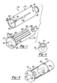
- Fig. 1 is a perspective view of a respiratory exercise apparatus in accordance with the present invention;
- Fig. 2 is an end view of the respiratory exercise apparatus of the present invention as viewed from the mouthpiece.
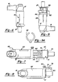
- Fig. 3 is a partially cut away perspective view of a further embodiment of the present invention.
- Fig. 4 is an exploded perspective view of a further embodiment of the present invention.
- Fig. 5 is a side view of the breathing device of figure 4 in the vertical position.
- Fig. 6 is a side view of the breathing device of figure 5 rotated 180°.
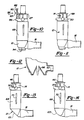
- Fig. 7 is a side view of the breathing device of figure 4 in the horizontal position.
- Figs. 8 through 11 illustrate various flow meters.
- Fig. 12 is a partial cut away view of the breathing device base.
- Figs. 13 and 14 illustrate modified breathing devices having slanted bases.
- With reference to Figure 1, the breathing apparatus of the present invention is generally shown at 10. The breathing apparatus includes a
main body 12 and aninner member 14, which is preferably a cylindrical tube. In the illustrated embodiment, themain body 12 is also illustrated as a cylindrical tube, but it should be understood that the shape of themain body 12 could be any desired shape. Further, if the breathing device does not include the percussion exercise, theinner member 14 could be any desired shape which would allow reciprocal movement with respect to themain body 12. - The
main body 12 has amouthpiece 16 attached to aflange 18. Theflange 18 is preferably angled at about 45° and includes abore 20 that communicates with the interior 22 of themain body 12. In the preferred embodiment, themouthpiece 16 is sufficiently flexible to be stretched overflange 18 to change the angle of the mouthpiece from 45° to generally in line with themain body 12. Theopposite end 24 of themain body 12 is open for receipt of theinner cylinder 14. Theinner cylinder 14 has aclosed end 26 and anopen end 28 with theopen end 28 being inserted intomain body 12. Aknob 30 extends from theend 26 so that theinner cylinder 14 can be manually rotated or reciprocated within themain body 12. In the preferred embodiment, the main body is 90.602 mm (3.567") long, which includes themouthpiece 16, and the inner cylinder is 93.218 mm (3.67") if theknob 30 is included. The main body and inner cylinder are made of polycarbonate or other moldable plastic, such as polyethylene. - The breathing apparatus 10 is adapted for exercising a users lungs through inspiration and expiration against resistance pulsing and percussion. The apparatus 10 has two sets of openings that can be aligned to provide resistance, pulsing or percussion exercises. By rotating the
inner cylinder 14 with respect to themain body 12, the different sets of openings can be aligned and locked in position to allow for a selected exercise. - In the illustrated embodiment, the
main body 12 has ahole 32 and a pair of elongated openings orslots inner cylinder 14 has a plurality of pairedholes slots 44 which extend through theinner cylinder 14. Theseholes slots 44 are positioned to align with theholes 32 andelongated slots inner cylinder 14 is rotated with respect to themain body 12. When theholes hole 32, resistance exercises can be performed. A set ofgrooves 46 which correspond to theholes 42 are provided in the inner cylinder for holding theinner cylinder 14 with respect to themain body 12.Grooves 46 are adapted to receive a lockingmember 50 to lock the cylinder in position once anappropriate hole 42 is aligned withhole 32. - When percussive exercises are desired, the
slots grooves 48 are provided, which correspond to theslots 44.Grooves 48 extend circumferentially about the cylinder to restrict movement of thecylinder 14 andmain body 12 so that only the slots are aligned for percussive exercises. As will be further described below, thegrooves 48 permit limited rotational movement ofcylinder 14 with respect tomain body 12. - When pulsing is desired, the locking member is inserted into a
longitudinally extending groove 49, which extends along the inner cylinder. This groove allows theinner cylinder 14 to reciprocate with respect to themain body 12. - In the disclosed embodiment, the locking
member 50 is a small bolt that is threaded into a threaded bore. A raisedportion 51 prevents themember 50 from being threaded too far into the grooves. The bolt can be screwed into the groove as desired. It should be understood that other types of locking members could be used, such as a spring loaded detent, a fixed detent, etc. - The
grooves 46, which correspond to theholes inner cylinder 14. Preferably, the lockingmember 50 has a diameter that is less than the length and width of thegroove 46 so that the inner cylinder can reciprocate slightly within themain body 12. Due to the movement of theinner cylinder 14 with respect to themain body 12, the resistance against exhaling can be increased; i.e., the ability to exhale is further restricted, due to the shifting from thehole 43 to thehole 43. When the user inhales, theinner cylinder 14 is pulled back into themain body 12 to shift fromhole 43 tohole 42, reducing resistance upon inhalation. - It should be appreciated that by locating the
holes inner cylinder 14 with respect to themain body 12. Again, since the inner holes are sliding with respect to theouter hole 32 inmain body 12, the resistance is changed. - In the preferred embodiment, the hole sets 42 and 43 have different diameters to provide varied resistance, depending upon whether the user is exhaling or inhaling. In the preferred embodiment, the diameters of the
holes 42 are 4.75 mm (.187"), 3.96 mm (.156"), 3.18 mm (.125") and 2.36 mm (.093"); the diameters ofholes 43 are 2.77 mm (.109"), 2.36 mm (.093"); 1.98 mm (.078"), and 1.57 mm (.062"); and the diameter of thehole 32 is 4.75 mm (.187"). By rotating thecylinder 14, various resistances can be selected and then automatically varied. Further, in the preferred embodiment, there aregrooves 46 corresponding to each hole set 42 and 43. Alignment holes 26 are provided inflange 27. Theseholes 26 correspond in size to their corresponding holes. By locating the holes with the lockingmember 50, the desiredholes diameter hole 42 with thehole 32, the lockingmember 50 can be inserted into the adjacent groove. In the disclosed embodiment, there are four (4) sets ofholes grooves 46 and onehole 32. Theholes grooves 46 are also separated into two sets with each set about 180° apart and the grooves in each set being about 30° apart. The hole sets 42 and 43 and thegrooves 46 are about 90° apart. - With the
mouthpiece 16 angled at approximately 45°, the air that escapes fromhole 32 blows against the user's face. This provides the user with an indication of the effort being expended and can function as an incentive to continue exhaling effectively. - Percussion is dependent upon
grooves 48 which extend between thegrooves 46 and correspond to the alignment of theinner slots 44 and theouter slots 34. In the preferred embodiment, eachgroove 48 extends circumferentially about the inner cylinder through an arc which is greater than 90°. When the lockingmember 50 is positioned in one of thegrooves 48, theinner cylinder 14 can be rotated with respect to themain body 12 through an arc defined by the groove; i.e., approximately 90°. When theinner cylinder 14 is rotated, theslots 44 sweep by theslots 34 to rapidly open and close the slots and rapidly block and open the ingress and egress of air into and out of the breathing apparatus 10. This rapid action causes a percussive result in the users lungs. It should be appreciated by those of ordinary skill in the art that this invention permits percussive exercising of the lungs on inhalation and exhalation. - In the disclosed embodiment, the
grooves 48 are positioned apart by about 180°. Each groove is adjacent the end of theslots 44 and extends circumferentially beyond the slots a slight distance to enhance the percussive effect the user receives upon use. Preferably, there are two sets ofslots 44 and twogrooves 48. Only one set ofslots 44 andgrooves 48 are shown. Additionally, there are preferably two sets ofslots 34 on opposed sides ofmain body 12. Thegroove 48 opposite the alignedslot 44 is the groove that receives the lockingmember 50. It should be appreciated that thegroove 48 adjacent theslot 44 could be used if the locking member or theslot 34 were repositioned during manufacture. - In the preferred embodiment, the
slots slots slots notch 49 is provided to permit easier alignment of theslots notch 49 with lockingmember 50, the slots are automatically aligned. - To provide pulsing exercise, the
groove 49 is aligned with lockingmember 50. Asmaller notch 51 is provided to facilitate proper alignment. By aligningnotch 51 with lockingmember 50,groove 49 is directly beneath lockingmember 50 and can then receive lockingmember 50.Groove 49 allows the inner cylinder to reciprocate with respect to themain body 12 as the user exhales. With the unit pointed up, the user exhales and the inner cylinder is raised to exposeslots 44. Whenslots 44 are exposed, theinner cylinder 14 drops down momentarily until pressure from the exhaled air increases in thecylinder 14 to raise it again. This repeated raising and dropping causes a pulsing effect on the lungs. - To use the breathing device, the
inner cylinder 14 is rotated with respect to themain body 12 to align either theholes slots groove 49. If resistance exercising is desired, then the holes are aligned. If percussion is desired, then the slots are aligned. If pulsing is desired, then groove 49 is aligned. Once aligned, the lockingmember 50 is threaded into the adjacent groove. Once the desired exercise is selected, the user inhales and exhales into themouthpiece 16. If resistive exercising is selected, theinner cylinder 14 reciprocates within themain body 12 to automatically adjust the resistance, or the user can manually control the relative resistance by controlling the amount of reciprocal movement of theinner cylinder 14. If percussion is selected, theinner cylinder 14 is manually rotated by the user as the user inhales and exhales.Knob 30 facilitates rotation ofinner cylinder 14 with respect tomain body 12. If pulsing is desired, the user usesgroove 49. - With reference to figure 4, a further embodiment of the present invention is shown. In this embodiment, a
weight 60 is positioned in theinner cylinder 14. The weight is illustrated as a rod, but it could be a ball, a disk attached to theflange 27, a spring, etc. Theweight 60 facilitates the reciprocal movement of theinner cylinder 14 with respect to themain body 12. Theweight 60forces cylinder 14 out of themain body 12 to further restrict inhalation and exhalation or with pulsing to forcecylinder 14 back into themain body 12. - With reference to figure 4, a further embodiment of the present invention is illustrated generally at 66. In this embodiment, there is a
main body 12, aninner member 14 and amouthpiece 16 as in the previous embodiment illustrated in figures 1 through 3. The main body is about 101.6 mm (4 inches) long and 31.25 mm (1.25 inches) in diameter; theinner member 14 is sized to fit into themain body 12. However,breathing device 66 provides for additional exercises as well as the exercises that can performed with the previously described breathing device 10. Theinner member 14 has been modified and covers are provided to allow for the additional exercises. Additionally, themouthpiece 16 is mounted to ashort nipple 62 that extends out of themain body 12 at about a 90° angle to thelongitudinal centerline 64 ofmain body 12. Thenipple 62 is a 22.23 mm (7/8 inch) diameter protrusion with a 19.05 mm (3/4 inch) inside diameter. The orientation ofmouthpiece 16 at a 90° angle allows the user of the breathing apparatus to twist themouthpiece 16 onnipple 62 to perform various exercises which will be described more fully below and to vary the resistance when performing these exercises. - As with the previous embodiment,
inner member 14 ofdevice 66 is inserted into the end ofmain body 12 so that it can be reciprocated and rotated with respect tomain body 12. Aknob 30 extends from the end ofinner member 14 to rotate and reciprocate theinner member 14. - In addition to the previously described exercises of resistance, pulsing or bouncing and percussion;
breathing device 66 also permits a pumping mode and a slow sustained maximal expiration and inspiration mode. It also includes a spring 69 to enhance the movement of theinner member 14 in the pulsing or bouncing mode. To simplify the description, the same reference numbers will be used to identify the same features found in the previous embodiment. Unless otherwise indicated, the same functions are associated with the same elements. As before, resistance exercises are provided by aligning the thumb screw withgrooves 46, of which there are three in this device, with one being out of view. Withscrew 50 ingroove 46 hole sets 42 and 43 are aligned with opening 32 (which is also not illustrated in this figure but is illustrated in figure 1). In the preferred, there are three sets ofholes holes grooves 46, or which there are three, are approximately 15.88 mm (5/8 inches) in length. Thelocation grooves 46 align corresponding hole sets 42 and 43 with theexhaust opening 32. In the preferred embodiment,exhaust hole 32 is about 6.35 mm (1/4 inch) in diameter. Percussion exercises are performed by aligningslots 44 withslots 34. In the preferred embodiment, there are two groups of sixpercussion slots 44 located 180° apart from one another. The slots are preferably 1.59 mm (1/16 inch) wide by 12.7 mm (1/2 inch) long. Theslots 34 are in two pairs, 180° apart and are 1.59 mm (1/16 inch) wide by 12.7 mm (1/2 inch) long. Agroove 48 is provided in theinner member 14 to accept thethumbscrew 50.Groove 48 is also not shown in this embodiment, since it is out of view; however, it is shown in figure 1. When pulsing is desired, thethumbscrew 50 is inserted intogroove 49. As before, theinner cylinder 14 reciprocates with respect to themain body 12. As illustrated, a spring 69 is mounted in thegroove 49. Thethumbscrew 50 when inserted intogroove 49 engages one end of the spring and acts against the spring to bias movement of theinner member 14. In this operation mode, theslots 34 andopening 32 in the main body are covered to prevent air from escaping through them. Theslots 34 andopening 32 are preferably covered by theinner member 14. However, other methods of covering the openings could be used, such as for example aflexible sleeve 68 that can be snapped over thebody member 12. Thissleeve 68 can be rotated to close oropen slots 34 andopening 32 by aligning theslot 70 and opening 71 of thesleeve 68 over theslots 44 andopening 32. Still further, the main body could be made without theopening 32 andlots 34. - In the pulse mode, the user exhales and the
inner member 14 slides away frommain body 12 and compresses the spring 69. The spring provides resistance to the outward movement of theinner member 14. When theopenings 44 are exposed from themain body 12, air exhaled by the user escapes through the exposedopenings 44 and theinner member 14 snaps back into themain body 12 due to the bias of the spring 69 and theweight 60. In the preferred embodiment, the weight is about 12.7 mm (1//2 inch) in diameter by 38.1 mm (1 1/2 inches) in length. As the user continues to exhale, movement of theinner member 14 in and out ofbody 12 occurs very rapidly providing a bounce or pulse action. The snap back action rapidly closes and opens the air passages in thedevice 66 interrupting the flow of air creating resistance. This pulsing or bouncing action causes a very pronounced change in pressure in the lungs loosening mucous and strengthening the lungs. Preferably in the pulse mode, the user inhales deeply and then exhales into themouthpiece 16 completely until all bouncing movement stops. The user then inhales deeply and repeats the exercise. - Slow sustained maximal expiration and inhalation can also be performed with this invention. With reference to figure 5, by rotating the
inner cylinder 14 to align thethumbscrew 50 with one of thegrooves 46, theinner member 14 can reciprocate out ofmain body 12 about 12.7 mm (1/2 inch). As illustrated in figure 4, theslots 44 do not extend into the area adjacent the longitudinal extent ofgrooves 46. In this mode, the only air passage which is open is the air passage created by aligning theopenings opening 32. If desired, this air passage can be closed by holding a finger over the air passage or by rotating thecover 68 over the passage. If the passage is closed, air can still escape from thedevice 66, but it is greatly restricted. - In the preferred embodiment, the air passage created by
openings openings main body 12 upright in a vertical position, the user can exhale into the mouthpiece and raise theinner member 14. As long as there is sufficient air in the user's lungs to overcome the weight of theinner member 14, in the gravitational pull, theinner member 14 will remain raised. As soon as all sufficient air is expelled from the user's lungs, the inner member will drop back into thebody member 16. The resistance can be varied by turning themouthpiece 16 at a different angle on thenipple 62 and by selecting one of theother grooves 46. By angling themouthpiece 16, themain body 12 andinner member 14 are angled with respect to the vertical which reduces resistance. - By rotating the
breathing device 66 180° theinner member 14 points downwardly, see figure 6. The user can then inhale completely so that theinner cylinder 14 snaps up into themain body 12. When the lungs are completely filled, themain body 12 will drop down due to theweight 60 pulling theinner member 14 down. Again, by angling themouthpiece 16, the resistance can be varied. In this mode the user experiences slow sustained maximal inspiration. - The other exercise that can be used is the pump mode. In this mode, illustrated in figure 7, an
internal cover 74 is used to partially coverslots 44 which are adjacentclosed end 26 and cover 68 is used to coverslot 34 andopening 32. Thebreathing device 66 is turned so thatmain body 12 is generally horizontal. Thethumbscrew 50 is inserted intogroove 49 or anadditional groove 47 could be used, as illustrated in figure 7. The user can then reciprocate theinner member 14 with respect to thebody member 12 as the user inhales and exhales, seearrow 45 in figure 7. As should be appreciated, themouthpiece 16 is twisted on thenipple 62. The user inhales completely while quickly moving theinner member 14 in and out of themain body 12. The same is done while the user exhales completely. This mode very effectively maximizes air pressure changes created by the pumping action. This mode provides an effect similar to that achieved in the percussion mode. - With reference to figures 8 through 11, flow meters or progress meters are illustrated to indicate the amount of air flow and progress a user is making using the breathing devices of the present invention. In figure 8, the
flow meter 76 attaches onto the end of themain body 12 at thethumbscrew 50. The thumbscrew can be used to hold themeter 76 in position. In the preferred embodiment,flowmeter 76 flexes slightly to allow theinner cylinder 14 to move along thenotches 78. The edge of themeter 76 has a plurality ofnotches 78 with cam surfaces 80. Theinner member 14 engages the cam surfaces 80 as it slides out of themain body 12 and gently forcesmeter 76 back to allow theflange 27 to pass. When theinner member 14 stops sliding out of theinner member 14 it is held by a one of thenotches 78. Thenotches 78 are calibrated to indicate the air flow through thebreathing device 66. In the preferred embodiment, the inner member would be rotated to a groove, such as groove 72 and theslots 34 andopening 32 would be opened bycover 68 to insure thatinner member 14 is not blown out ofmain body 12. The calibration would take into account the flow lost through the open passages. - In figure 9, a further embodiment of a flow meter is shown generally at 82. In this embodiment, a
guide 84, see figure 9a, is snapped onto themain body 12 with anindicator rod 86 engaging theflange 27. Therod 86 is L-shaped to hook ontoflange 27 and includes graduations to indicate the amount of flow and progress. When the user exhales, therod 86 is moved and remains as theinner cylinder 14 returns. - In figure 10, a still further embodiment is illustrated. In this embodiment, a
removable rod 88 is rigidly mounted into a receptacle 90 formed in themain body 12. Additionally, therod 88 could be attached to thethumbscrew 50. Anindicator 92 is reciprocally mounted about therod 88. The disclosedindicator 92 is anylon washer 93 and feltwasher 95 which can slide alongrod 88. The washers engage theflange 27 and are moved along therod 88. The felt washer remains to indicate the air flow and progress of the user. In this embodiment, therod 88 can be inserted into anopening 94 formed in the base ofmain body 12. - In figure 11, another embodiment of a flow meter is illustrated. In this embodiment, the
inner member 14 has graduated markings 99. As the user exhales, the mark on theinner member 14 will rise to indicate the air flow and progress. The user will be able to view the height reached and determine flow and progress. - In figure 12, an
oxygen connector 98 is illustrated. In the disclosed embodiment theconnector 98 is inset inmain body 12; however, it could be externally mounted. Figures 13 and 14 illustrate further embodiments which have a slantedbase 101 in figure 13 and 103 in figure 14. The slanted base facilitates air flow frommouthpiece 16 through themembers - In accordance with the provisions of the patent statutes, the present invention has been described in what is considered to represent its preferred embodiment. However, it should be noted that the invention can be practiced otherwise than as specifically illustrated and described without departing from the scope of the claims.
Claims (11)
- A lung exercising device comprising:a main body;an inner member reciprocally and rotatably mounted within the main body;a mouthpiece mounted to the main body and in communication with the inner member;at least one opening in the inner member and at least one opening in the main body adapted to be in selective communication to define an air passage extending from the mouth piece through the inner member and out of the main body, the air passage being selectively variable upon rotational or reciprocal movement of the inner member with respect to the main body.whereby the lung exercising device can provide various exercises for the lungs by manipulation of the inner member with respect to the main body.
- The lung exercising device of claim 1, wherein the openings in the inner member include at least two apertures of different diameter spaced longitudinally along the inner member and adapted to communicate with the at least one opening in the main body as the inner member reciprocates within the main body;
whereby the user of the device can exhale and inhale into the mouthpiece to reciprocate the inner member with respect to the main body and automatically vary the resistance between inhalation and exhalation. - The lung exercising device of claim 2, wherein the openings in the inner member include a plurality of apertures separated into pairs to provide further selective resistance to inhaling and exhaling.
- The lung exercising device of claim 1, wherein the openings in the inner member and main body include slots which can be selectively aligned to define the air passage.
- The lung exercising device of claim 1, wherein the openings in the inner and main body are slots that can be selectively aligned by rotating the inner member with respect to the main body and thereby open and close the air passage as the slots pass over one another;
thereby creating a percussive action upon the user's lungs as the user inhales and exhales into the mouthpiece. - The lung exercising device of claim 1, wherein the openings in the inner member include at least two apertures of different diameter spaced longitudinally along the inner member which are adapted to communicate with the at least one opening in the main body as the inner member reciprocates within the main body; and
the openings in the inner member and main body include slots that can be selectively aligned by rotating the inner member with respect to the main body and thereby open and close the air passage as the slots pass over one another;
a control selector for selecting between the apertures and slots;
thereby creating a percussive action upon the user's lungs as the user inhales and exhales into the mouthpiece if the slots are selected or if the apertures are selected the user can reciprocate the inner member with respect to the main body and automatically vary the resistance between inhalation and exhalation. - The lung exercising device of claim 6, wherein the control selector includes a pin and grooves, the grooves being associated with either the slots or the apertures to provide the desired exercise.
- The lung exercising device of claim 1, wherein the inner member is adapted to be reciprocated with respect to the main body by the user exhaling into the mouthpiece and raising the inner member, the openings being initially covered by the main body but being exposed as the inner member is raised with respect to the main body resulting in the inner member dropping back into the main body to be immediately raised with respect to the main body as the user continues to exhale;
whereby the user receives a rapid pulsing effect upon the lungs. - The breathing apparatus of claim 1, wherein said inner member and said main body have a plurality of grooves divided into at least first and second groups of grooves and a mating stop member, one of said groups of grooves having grooves which extend circumferentially with respect to said inner member and main body permitting rotational movement of said inner member with respect to said main body, said stop member mating with said grooves to control the extent of rotational movement, said rotational movement permitting percussive exercising;
the outer group of grooves having grooves which extend longitudinally with respect to said inner member and main body permitting reciprocal movement of said inner member with respect to said main body, said stop member mating with said other group of grooves to control the extent of reciprocal movement. - The lung exercising device of claim 1, further including a progress measuring device.
- The lung exercising device of claim 1, further including a spring biasing the inner member with respect to the main body to resist the inner member from being moved with respect to the main body and to assist the return of the inner member with respect to the main body.
Applications Claiming Priority (3)
| Application Number | Priority Date | Filing Date | Title |
|---|---|---|---|
| US08/478,741 US5658221A (en) | 1995-02-10 | 1995-06-07 | Portable personal breathing apparatus and method of using same |
| US478741 | 1995-06-07 | ||
| PCT/US1996/009410 WO1996040376A1 (en) | 1995-06-07 | 1996-06-07 | A portable, personal breathing apparatus |
Publications (3)
| Publication Number | Publication Date |
|---|---|
| EP0836518A1 EP0836518A1 (en) | 1998-04-22 |
| EP0836518A4 EP0836518A4 (en) | 2000-11-15 |
| EP0836518B1 true EP0836518B1 (en) | 2006-12-06 |
Family
ID=23901176
Family Applications (1)
| Application Number | Title | Priority Date | Filing Date |
|---|---|---|---|
| EP96918299A Expired - Lifetime EP0836518B1 (en) | 1995-06-07 | 1996-06-07 | A portable, personal breathing apparatus |
Country Status (9)
| Country | Link |
|---|---|
| US (2) | US5658221A (en) |
| EP (1) | EP0836518B1 (en) |
| JP (1) | JP3912796B2 (en) |
| CN (1) | CN1191494A (en) |
| AT (1) | ATE347407T1 (en) |
| AU (1) | AU6098996A (en) |
| CA (1) | CA2223518C (en) |
| DE (1) | DE69636751T2 (en) |
| WO (1) | WO1996040376A1 (en) |
Families Citing this family (78)
| Publication number | Priority date | Publication date | Assignee | Title |
|---|---|---|---|---|
| US6083141A (en) * | 1995-02-10 | 2000-07-04 | Hougen; Everett D. | Portable respiratory exercise apparatus and method for using the same |
| GB9514108D0 (en) * | 1995-07-11 | 1995-09-13 | Clement Clarke Int | A training device for a ventilatory capacity meter |
| US6533739B1 (en) | 1995-11-21 | 2003-03-18 | The Penn State Research Foundation | Chest brace and method of using same |
| US5899832A (en) * | 1996-06-14 | 1999-05-04 | Hougen; Everett D. | Compact lung exercising device |
| US6058932A (en) * | 1997-04-21 | 2000-05-09 | Hughes; Arthur R. | Acoustic transceiver respiratory therapy apparatus |
| GB2325410A (en) * | 1997-05-21 | 1998-11-25 | James William Carlyle | Respiratory muscle training device |
| US6042509A (en) * | 1997-08-27 | 2000-03-28 | Wu; Race | Device for promoting human abdominal breathing |
| DE19903795B4 (en) * | 1999-02-01 | 2004-08-26 | Medisize B.V. | Breathing training device to improve vital capacity |
| US6379316B1 (en) * | 1999-08-31 | 2002-04-30 | Advanced Respiratory, Inc. | Method and apparatus for inducing sputum samples for diagnostic evaluation |
| US6210345B1 (en) | 1999-10-04 | 2001-04-03 | American Biosystems, Inc. | Outcome measuring airway resistance diagnostic system |
| US6581598B1 (en) * | 1999-11-24 | 2003-06-24 | Dhd Healthcare Corporation | Positive expiratory pressure device |
| US6776159B2 (en) | 1999-11-24 | 2004-08-17 | Dhd Healthcare Corporation | Positive expiratory pressure device with bypass |
| US7059324B2 (en) * | 1999-11-24 | 2006-06-13 | Smiths Medical Asd, Inc. | Positive expiratory pressure device with bypass |
| CA2826724C (en) | 2000-04-11 | 2016-02-02 | Trudell Medical International | Aerosol delivery apparatus with positive expiratory pressure capacity |
| WO2001095786A2 (en) * | 2000-06-16 | 2001-12-20 | Rajiv Doshi | Methods and devices for improving breathing in patients with pulmonary disease |
| US20030205226A1 (en) | 2002-05-02 | 2003-11-06 | Pre Holding, Inc. | Aerosol medication inhalation system |
| US6904908B2 (en) | 2002-05-21 | 2005-06-14 | Trudell Medical International | Visual indicator for an aerosol medication delivery apparatus and system |
| US6718969B1 (en) * | 2002-05-28 | 2004-04-13 | Darren Rubin | Medication dosage inhaler system |
| US7191780B2 (en) * | 2003-09-22 | 2007-03-20 | Comedica Incorporated | Continuous high-frequency oscillation breathing treatment apparatus |
| US8061357B2 (en) * | 2004-12-08 | 2011-11-22 | Ventus Medical, Inc. | Adhesive nasal respiratory devices |
| US9833354B2 (en) | 2004-12-08 | 2017-12-05 | Theravent, Inc. | Nasal respiratory devices |
| US10610228B2 (en) | 2004-12-08 | 2020-04-07 | Theravent, Inc. | Passive nasal peep devices |
| JP5230202B2 (en) * | 2004-12-08 | 2013-07-10 | ヴェンタス・メディカル・インコーポレーテッド | Breathing device and kit |
| WO2006107117A1 (en) * | 2005-04-04 | 2006-10-12 | Kenji Okoshi | Carbon dioxide exposure respiration training tool |
| SE531316C2 (en) * | 2005-04-19 | 2009-02-17 | Kenneth Eliasson | An adjustable breathing resistance |
| US7785280B2 (en) | 2005-10-14 | 2010-08-31 | Hill-Rom Services, Inc. | Variable stroke air pulse generator |
| US8333728B2 (en) * | 2005-12-01 | 2012-12-18 | Medtronic, Inc. | Implantable cerebrospinal fluid flow device and method of controlling flow of cerebrospinal fluid |
| RU2306161C1 (en) * | 2006-01-24 | 2007-09-20 | Яков Абраммерович Гольдштейн | Breathing training device |
| US8460223B2 (en) | 2006-03-15 | 2013-06-11 | Hill-Rom Services Pte. Ltd. | High frequency chest wall oscillation system |
| GB0610171D0 (en) | 2006-05-23 | 2006-06-28 | Robitaille Jean Pierre | Valved nasal canula |
| AU2007267970B2 (en) | 2006-05-23 | 2011-05-26 | Ventus Medical, Inc. | Nasal respiratory devices |
| EP2032214B1 (en) * | 2006-06-07 | 2017-12-06 | Theravent, Inc. | Layered nasal devices |
| WO2007146189A2 (en) | 2006-06-07 | 2007-12-21 | Ventus Medical, Inc. | Nasal respiratory devices for positive end-expiratory pressure |
| CA2661152A1 (en) | 2006-08-21 | 2008-02-28 | Trudell Medical International | Respiratory muscle endurance training device and method for the use thereof |
| US7779841B2 (en) | 2006-11-13 | 2010-08-24 | Carefusion 2200, Inc. | Respiratory therapy device and method |
| US8240309B2 (en) * | 2006-11-16 | 2012-08-14 | Ventus Medical, Inc. | Adjustable nasal devices |
| US8020700B2 (en) | 2007-12-05 | 2011-09-20 | Ventus Medical, Inc. | Packaging and dispensing nasal devices |
| AU2008331443B2 (en) * | 2007-12-08 | 2010-11-04 | Efthimiou, Dimitrios Mr | Personal air filter with amplifier and vibrator |
| EP2338575B1 (en) | 2008-02-21 | 2017-05-31 | Trudell Medical International | Respiratory muscle endurance training device and method for the use thereof |
| US8251876B2 (en) | 2008-04-22 | 2012-08-28 | Hill-Rom Services, Inc. | Breathing exercise apparatus |
| US8539951B1 (en) | 2008-05-27 | 2013-09-24 | Trudell Medical International | Oscillating positive respiratory pressure device |
| US8327849B2 (en) | 2008-10-28 | 2012-12-11 | Trudell Medical International | Oscillating positive expiratory pressure device |
| US9149589B2 (en) | 2009-02-23 | 2015-10-06 | Trudell Medical International | Method and device for performing orientation dependent oscillating positive expiratory pressure therapy |
| US8485179B1 (en) | 2009-02-23 | 2013-07-16 | Trudell Medical International | Oscillating positive expiratory pressure device |
| US8408211B2 (en) * | 2009-12-11 | 2013-04-02 | Ruthanna DeJule | Method of facilitating inhalation of controlled quantities of exhaled air |
| US8177689B2 (en) * | 2010-03-01 | 2012-05-15 | Bas Rutten | Oxygen trainer device |
| US8875711B2 (en) | 2010-05-27 | 2014-11-04 | Theravent, Inc. | Layered nasal respiratory devices |
| US9084859B2 (en) | 2011-03-14 | 2015-07-21 | Sleepnea Llc | Energy-harvesting respiratory method and device |
| RU2615280C2 (en) | 2011-06-06 | 2017-04-04 | Труделл Медикал Интернешнл | Device with oscillatory positive pressure at exhalation |
| EP2760390B1 (en) | 2011-09-29 | 2019-06-12 | Trudell Medical International | Nasal insert |
| US9180271B2 (en) | 2012-03-05 | 2015-11-10 | Hill-Rom Services Pte. Ltd. | Respiratory therapy device having standard and oscillatory PEP with nebulizer |
| US9517315B2 (en) | 2012-11-30 | 2016-12-13 | Trudell Medical International | Oscillating positive expiratory pressure device |
| US9795752B2 (en) | 2012-12-03 | 2017-10-24 | Mhs Care-Innovation, Llc | Combination respiratory therapy device, system, and method |
| US9770566B2 (en) | 2013-02-13 | 2017-09-26 | Jessica Meyers | Spirometer device with visual aid for therapeutic breathing |
| EP2783728B1 (en) * | 2013-03-26 | 2016-12-14 | R. Cegla GmbH & Co. KG | Therapy device for the treatment of respiratory diseases |
| CA2915949C (en) | 2013-07-12 | 2020-01-28 | Trudell Medical International | Huff cough simulation device |
| US9849257B2 (en) | 2013-08-22 | 2017-12-26 | Trudell Medical International | Oscillating positive respiratory pressure device |
| US10363383B2 (en) | 2014-02-07 | 2019-07-30 | Trudell Medical International | Pressure indicator for an oscillating positive expiratory pressure device |
| US10004872B1 (en) | 2015-03-06 | 2018-06-26 | D R Burton Healthcare, Llc | Positive expiratory pressure device having an oscillating valve |
| CN107735135B (en) | 2015-04-02 | 2020-06-26 | 希尔-罗姆服务私人有限公司 | Manifold for a respiratory device |
| MX2018001321A (en) * | 2015-07-30 | 2018-08-15 | Trudell Medical Int | Combined respiratory muscle training and oscillating positive expiratory pressure device. |
| USD780906S1 (en) | 2015-09-02 | 2017-03-07 | Trudell Medical International | Respiratory treatment device |
| USD778429S1 (en) | 2015-09-02 | 2017-02-07 | Trudell Medical International | Respiratory treatment device |
| US10857317B2 (en) | 2015-12-04 | 2020-12-08 | Trudell Medical International | Huff cough simulation device |
| US9861779B1 (en) * | 2016-06-21 | 2018-01-09 | George Ashford Reed | Positive expiratory pressure device |
| US11433195B2 (en) * | 2016-08-25 | 2022-09-06 | Todd Joseph Steinberg | Breathing device and method of controlling breathing using the device |
| EP3618908A4 (en) | 2017-05-03 | 2021-01-13 | Trudell Medical International | Combined oscillating positive expiratory pressure therapy and huff cough simulation device |
| US10953278B2 (en) | 2018-02-02 | 2021-03-23 | Trudell Medical International | Oscillating positive expiratory pressure device |
| CN108568063B (en) * | 2018-04-25 | 2021-05-07 | 陈苑萍 | Breathing blocking trainer |
| US10589040B1 (en) | 2019-03-28 | 2020-03-17 | Thayer Medical Corporation | Collapsible, disposable MDI spacer and method |
| US11383051B2 (en) | 2019-03-28 | 2022-07-12 | Thayer Medical Corporation | Collapsible, disposable medication inhalation spacer and method |
| US11638792B2 (en) | 2019-03-28 | 2023-05-02 | Thayer Medical Corporation | Collapsible, disposable medication inhalation spacer and method |
| US11266797B2 (en) | 2019-03-28 | 2022-03-08 | Thayer Medical Corporation | Collapsible, disposable medication inhalation spacer and method |
| US10780318B1 (en) * | 2019-04-18 | 2020-09-22 | Firas Kasem Ghazzawi | Breathing device with exhale and inhale valve to create resistance |
| CN111450373A (en) * | 2020-05-06 | 2020-07-28 | 西安交通大学医学院第一附属医院 | Tracheotomy connection composite device |
| WO2022072380A1 (en) * | 2020-09-29 | 2022-04-07 | Sebastiaan Rutten | Oxygen trainer device |
| CN114432669A (en) * | 2022-02-17 | 2022-05-06 | 张兴伟 | Pediatric respiratory training device |
| CN114984532B (en) * | 2022-05-11 | 2023-09-08 | 南京善若网络科技有限公司 | Paediatrics pulmonary function rehabilitation exercise equipment |
Family Cites Families (46)
| Publication number | Priority date | Publication date | Assignee | Title |
|---|---|---|---|---|
| US515637A (en) * | 1894-02-27 | Breathing-tube | ||
| US3079A (en) * | 1843-05-08 | Breathing-tube | ||
| US635232A (en) * | 1899-02-16 | 1899-10-17 | Sterling Company Ltd | Breathing-tube. |
| US737008A (en) * | 1902-10-16 | 1903-08-25 | Peter Elder Nichol | Lung and voice developer. |
| US856432A (en) * | 1905-12-07 | 1907-06-11 | George Morley Thomson | Device for developing the lungs. |
| US940735A (en) * | 1908-12-11 | 1909-11-23 | Victor J Schaeffer | Apparatus for developing the lungs. |
| US1295118A (en) * | 1918-04-06 | 1919-02-25 | Calvin L Canaday | Lung-exerciser. |
| US1392700A (en) * | 1920-09-21 | 1921-10-04 | Henry M Oyen | Lung-exercising device |
| US2292474A (en) * | 1940-01-09 | 1942-08-11 | Elisha W Paxton | Vacuum gauge |
| US3298362A (en) * | 1963-12-10 | 1967-01-17 | Jr Maxwell W Lippitt | Instrument for use in performing a controlled valsalva maneuver |
| US3333844A (en) * | 1964-08-17 | 1967-08-01 | Mary K Jurschak | Pressure exhaling exercising device |
| BE794580A (en) * | 1971-07-28 | 1973-05-16 | Connor Michael J O | RESPIRATOR |
| US3826247A (en) * | 1972-06-27 | 1974-07-30 | A Ruskin | Pulmonary achievement trainer |
| US3810461A (en) * | 1972-09-11 | 1974-05-14 | American Health Inc | Disposable pulmonary function kit |
| US3908987A (en) * | 1973-09-27 | 1975-09-30 | John R Boehringer | Controlled positive end pressure expiratory device |
| US3949984A (en) * | 1973-12-10 | 1976-04-13 | Joseph Navara | Breathing exerciser |
| US3972326A (en) * | 1974-01-23 | 1976-08-03 | Peter Nelson Brawn | Positive reinforcement respiratory inhalation device |
| US4054134A (en) * | 1975-09-15 | 1977-10-18 | Kritzer Richard W | Respirators |
| US4025070A (en) * | 1976-04-19 | 1977-05-24 | Cutter Laboratories, Inc. | Respiratory exerciser |
| US4062358A (en) * | 1976-04-21 | 1977-12-13 | Kritzer Richard W | Respirators |
| US4114616A (en) * | 1976-06-07 | 1978-09-19 | Peter Nelson Brawn | Positive reinforcement respiratory inhalation device |
| FR2379291A1 (en) * | 1977-02-04 | 1978-09-01 | Cahen Claude | Unit for treating bronchial ailment - has tube into which patient breathes to move piston against spring and magnetic pressure to uncover ports |
| US4155547A (en) * | 1977-09-27 | 1979-05-22 | Barrett John P Jr | Torsion spring type wrist exercising device |
| US4158360A (en) * | 1978-01-26 | 1979-06-19 | Projects In Health, Inc. | Expiratory flow meter |
| US4221381A (en) * | 1978-12-26 | 1980-09-09 | Albany International Corp. | Respiratory exerciser |
| US4275722A (en) * | 1979-05-04 | 1981-06-30 | Sorensen Harry D | Respiratory exerciser and rebreathing device |
| US4291704A (en) * | 1979-12-13 | 1981-09-29 | Dale E. Braddy | Spirometer device |
| US4345605A (en) * | 1980-10-20 | 1982-08-24 | Gereg Gordon A | Lung exerciser |
| US4473082A (en) * | 1980-10-20 | 1984-09-25 | Gereg Gordon A | Lung exerciser with variable resistance |
| US4403616A (en) * | 1981-06-09 | 1983-09-13 | K-Med, Inc. | Expiratory breathing exercise device |
| US4533137A (en) * | 1982-01-19 | 1985-08-06 | Healthscan Inc. | Pulmonary training method |
| US4444202A (en) * | 1982-03-31 | 1984-04-24 | Howard Rubin | Breathing exerciser |
| US4601465A (en) * | 1984-03-22 | 1986-07-22 | Roy Jean Yves | Device for stimulating the human respiratory system |
| US4635647A (en) * | 1984-09-07 | 1987-01-13 | Choksi Pradip V | Incentive spirometer employing bellows air flow sensor |
| US4739987A (en) * | 1985-10-28 | 1988-04-26 | Nicholson Marguerite K | Respiratory exerciser |
| US4770413A (en) * | 1987-04-27 | 1988-09-13 | Mba Healthcare Products, Inc. | Breathing exercise device |
| US4981295A (en) * | 1987-05-11 | 1991-01-01 | City Of Hope | Respiratory training using feedback |
| ATE89483T1 (en) * | 1987-08-14 | 1993-06-15 | Raupach Udo | RESPIRATORY THERAPY DEVICE. |
| DE3773396D1 (en) * | 1987-10-22 | 1991-10-31 | Varioraw Percutive Sa | RESISTANCE DEVICE AGAINST BREATHING TO IMPROVE LUNG VENTILATION. |
| US4854574A (en) * | 1988-03-15 | 1989-08-08 | 501 Healthscan, Inc. | Inspirator muscle trainer |
| EP0372148A1 (en) * | 1988-12-09 | 1990-06-13 | Erik Folke Norell | Lung exercising device |
| BE1004384A3 (en) * | 1989-08-03 | 1992-11-10 | Labaere Emmanuel | Device for applying on and techniques exhalation. |
| GB2238728B (en) * | 1989-09-25 | 1993-04-07 | Christopher Harry Hepburn | A lung and chest exerciser and developer |
| AU633199B2 (en) * | 1991-03-21 | 1993-01-21 | Kawaei Co., Ltd. | Apparatus for supporting deep breathing |
| US5255687A (en) * | 1992-01-21 | 1993-10-26 | Mckenna Charles L | Zero dead space respiratory exercise valve |
| US5263908A (en) * | 1992-11-04 | 1993-11-23 | Ping Chen | Multi-functional physical exercise apparatus |
-
1995
- 1995-06-07 US US08/478,741 patent/US5658221A/en not_active Expired - Lifetime
-
1996
- 1996-06-07 DE DE69636751T patent/DE69636751T2/en not_active Expired - Lifetime
- 1996-06-07 CA CA002223518A patent/CA2223518C/en not_active Expired - Fee Related
- 1996-06-07 WO PCT/US1996/009410 patent/WO1996040376A1/en active IP Right Grant
- 1996-06-07 AT AT96918299T patent/ATE347407T1/en not_active IP Right Cessation
- 1996-06-07 JP JP50173397A patent/JP3912796B2/en not_active Expired - Fee Related
- 1996-06-07 CN CN96195340A patent/CN1191494A/en active Pending
- 1996-06-07 EP EP96918299A patent/EP0836518B1/en not_active Expired - Lifetime
- 1996-06-07 AU AU60989/96A patent/AU6098996A/en not_active Abandoned
-
1997
- 1997-08-18 US US08/912,433 patent/US5910071A/en not_active Expired - Lifetime
Also Published As
| Publication number | Publication date |
|---|---|
| EP0836518A1 (en) | 1998-04-22 |
| US5910071A (en) | 1999-06-08 |
| DE69636751D1 (en) | 2007-01-18 |
| US5658221A (en) | 1997-08-19 |
| DE69636751T2 (en) | 2007-10-11 |
| AU6098996A (en) | 1996-12-30 |
| EP0836518A4 (en) | 2000-11-15 |
| JP3912796B2 (en) | 2007-05-09 |
| ATE347407T1 (en) | 2006-12-15 |
| CA2223518A1 (en) | 1996-12-19 |
| CN1191494A (en) | 1998-08-26 |
| CA2223518C (en) | 2009-05-12 |
| JPH11507258A (en) | 1999-06-29 |
| WO1996040376A1 (en) | 1996-12-19 |
Similar Documents
| Publication | Publication Date | Title |
|---|---|---|
| EP0836518B1 (en) | A portable, personal breathing apparatus | |
| US6083141A (en) | Portable respiratory exercise apparatus and method for using the same | |
| US5890998A (en) | Portable personal breathing apparatus | |
| US5899832A (en) | Compact lung exercising device | |
| US8663069B2 (en) | Respiratory muscle endurance training device and method for the use thereof | |
| US5193529A (en) | Applicance for use in inspiration and expiration techniques and exercises | |
| US8272378B2 (en) | System and method for improving endurance of inspiratory muscles | |
| US20070089740A1 (en) | Pursed lip breathing device | |
| US20060130839A1 (en) | Breathing apparatus for hypoxic pre-acclimatization and training | |
| NO333046B1 (en) | Device for painting inhalation strength | |
| US9233274B2 (en) | Combination spirometer and PEP breathing exerciser | |
| EP3265156B1 (en) | Positive expiratory pressure device having oscillation valve |
Legal Events
| Date | Code | Title | Description |
|---|---|---|---|
| PUAI | Public reference made under article 153(3) epc to a published international application that has entered the european phase |
Free format text: ORIGINAL CODE: 0009012 |
|
| 17P | Request for examination filed |
Effective date: 19971210 |
|
| AK | Designated contracting states |
Kind code of ref document: A1 Designated state(s): AT BE CH DE DK ES FI FR GB GR IE IT LI LU MC NL PT SE |
|
| A4 | Supplementary search report drawn up and despatched |
Effective date: 20000929 |
|
| AK | Designated contracting states |
Kind code of ref document: A4 Designated state(s): AT BE CH DE DK ES FI FR GB GR IE IT LI LU MC NL PT SE |
|
| 17Q | First examination report despatched |
Effective date: 20031205 |
|
| GRAP | Despatch of communication of intention to grant a patent |
Free format text: ORIGINAL CODE: EPIDOSNIGR1 |
|
| GRAS | Grant fee paid |
Free format text: ORIGINAL CODE: EPIDOSNIGR3 |
|
| RAP1 | Party data changed (applicant data changed or rights of an application transferred) |
Owner name: EVERETT D. HOUGEN IRREVOCABLE TRUST |
|
| RIN1 | Information on inventor provided before grant (corrected) |
Inventor name: EVERETT D. HOUGEN |
|
| GRAA | (expected) grant |
Free format text: ORIGINAL CODE: 0009210 |
|
| AK | Designated contracting states |
Kind code of ref document: B1 Designated state(s): AT BE CH DE DK ES FI FR GB GR IE IT LI LU MC NL PT SE |
|
| PG25 | Lapsed in a contracting state [announced via postgrant information from national office to epo] |
Ref country code: NL Free format text: LAPSE BECAUSE OF FAILURE TO SUBMIT A TRANSLATION OF THE DESCRIPTION OR TO PAY THE FEE WITHIN THE PRESCRIBED TIME-LIMIT Effective date: 20061206 Ref country code: LI Free format text: LAPSE BECAUSE OF FAILURE TO SUBMIT A TRANSLATION OF THE DESCRIPTION OR TO PAY THE FEE WITHIN THE PRESCRIBED TIME-LIMIT Effective date: 20061206 Ref country code: FI Free format text: LAPSE BECAUSE OF FAILURE TO SUBMIT A TRANSLATION OF THE DESCRIPTION OR TO PAY THE FEE WITHIN THE PRESCRIBED TIME-LIMIT Effective date: 20061206 Ref country code: DK Free format text: LAPSE BECAUSE OF FAILURE TO SUBMIT A TRANSLATION OF THE DESCRIPTION OR TO PAY THE FEE WITHIN THE PRESCRIBED TIME-LIMIT Effective date: 20061206 Ref country code: CH Free format text: LAPSE BECAUSE OF FAILURE TO SUBMIT A TRANSLATION OF THE DESCRIPTION OR TO PAY THE FEE WITHIN THE PRESCRIBED TIME-LIMIT Effective date: 20061206 Ref country code: BE Free format text: LAPSE BECAUSE OF FAILURE TO SUBMIT A TRANSLATION OF THE DESCRIPTION OR TO PAY THE FEE WITHIN THE PRESCRIBED TIME-LIMIT Effective date: 20061206 Ref country code: AT Free format text: LAPSE BECAUSE OF FAILURE TO SUBMIT A TRANSLATION OF THE DESCRIPTION OR TO PAY THE FEE WITHIN THE PRESCRIBED TIME-LIMIT Effective date: 20061206 |
|
| REG | Reference to a national code |
Ref country code: GB Ref legal event code: FG4D |
|
| REG | Reference to a national code |
Ref country code: CH Ref legal event code: EP |
|
| REG | Reference to a national code |
Ref country code: IE Ref legal event code: FG4D |
|
| REF | Corresponds to: |
Ref document number: 69636751 Country of ref document: DE Date of ref document: 20070118 Kind code of ref document: P |
|
| REG | Reference to a national code |
Ref country code: SE Ref legal event code: TRGR |
|
| PG25 | Lapsed in a contracting state [announced via postgrant information from national office to epo] |
Ref country code: ES Free format text: LAPSE BECAUSE OF FAILURE TO SUBMIT A TRANSLATION OF THE DESCRIPTION OR TO PAY THE FEE WITHIN THE PRESCRIBED TIME-LIMIT Effective date: 20070317 |
|
| PG25 | Lapsed in a contracting state [announced via postgrant information from national office to epo] |
Ref country code: PT Free format text: LAPSE BECAUSE OF FAILURE TO SUBMIT A TRANSLATION OF THE DESCRIPTION OR TO PAY THE FEE WITHIN THE PRESCRIBED TIME-LIMIT Effective date: 20070507 |
|
| NLV1 | Nl: lapsed or annulled due to failure to fulfill the requirements of art. 29p and 29m of the patents act | ||
| REG | Reference to a national code |
Ref country code: CH Ref legal event code: PL |
|
| ET | Fr: translation filed | ||
| PLBE | No opposition filed within time limit |
Free format text: ORIGINAL CODE: 0009261 |
|
| STAA | Information on the status of an ep patent application or granted ep patent |
Free format text: STATUS: NO OPPOSITION FILED WITHIN TIME LIMIT |
|
| 26N | No opposition filed |
Effective date: 20070907 |
|
| PG25 | Lapsed in a contracting state [announced via postgrant information from national office to epo] |
Ref country code: MC Free format text: LAPSE BECAUSE OF NON-PAYMENT OF DUE FEES Effective date: 20070630 |
|
| PG25 | Lapsed in a contracting state [announced via postgrant information from national office to epo] |
Ref country code: GR Free format text: LAPSE BECAUSE OF FAILURE TO SUBMIT A TRANSLATION OF THE DESCRIPTION OR TO PAY THE FEE WITHIN THE PRESCRIBED TIME-LIMIT Effective date: 20070307 |
|
| PG25 | Lapsed in a contracting state [announced via postgrant information from national office to epo] |
Ref country code: IE Free format text: LAPSE BECAUSE OF NON-PAYMENT OF DUE FEES Effective date: 20070607 |
|
| PG25 | Lapsed in a contracting state [announced via postgrant information from national office to epo] |
Ref country code: LU Free format text: LAPSE BECAUSE OF NON-PAYMENT OF DUE FEES Effective date: 20070607 |
|
| PGFP | Annual fee paid to national office [announced via postgrant information from national office to epo] |
Ref country code: FR Payment date: 20100630 Year of fee payment: 15 |
|
| PGFP | Annual fee paid to national office [announced via postgrant information from national office to epo] |
Ref country code: SE Payment date: 20100629 Year of fee payment: 15 Ref country code: IT Payment date: 20100629 Year of fee payment: 15 Ref country code: GB Payment date: 20100625 Year of fee payment: 15 Ref country code: DE Payment date: 20100629 Year of fee payment: 15 |
|
| REG | Reference to a national code |
Ref country code: SE Ref legal event code: EUG |
|
| GBPC | Gb: european patent ceased through non-payment of renewal fee |
Effective date: 20110607 |
|
| PG25 | Lapsed in a contracting state [announced via postgrant information from national office to epo] |
Ref country code: IT Free format text: LAPSE BECAUSE OF NON-PAYMENT OF DUE FEES Effective date: 20110607 |
|
| REG | Reference to a national code |
Ref country code: FR Ref legal event code: ST Effective date: 20120229 |
|
| REG | Reference to a national code |
Ref country code: DE Ref legal event code: R119 Ref document number: 69636751 Country of ref document: DE Effective date: 20120103 |
|
| PG25 | Lapsed in a contracting state [announced via postgrant information from national office to epo] |
Ref country code: FR Free format text: LAPSE BECAUSE OF NON-PAYMENT OF DUE FEES Effective date: 20110630 Ref country code: DE Free format text: LAPSE BECAUSE OF NON-PAYMENT OF DUE FEES Effective date: 20120103 |
|
| PG25 | Lapsed in a contracting state [announced via postgrant information from national office to epo] |
Ref country code: GB Free format text: LAPSE BECAUSE OF NON-PAYMENT OF DUE FEES Effective date: 20110607 |
|
| PG25 | Lapsed in a contracting state [announced via postgrant information from national office to epo] |
Ref country code: SE Free format text: LAPSE BECAUSE OF NON-PAYMENT OF DUE FEES Effective date: 20110608 |