EP0834840A1 - Action analyzing/recording system - Google Patents
Action analyzing/recording system Download PDFInfo
- Publication number
- EP0834840A1 EP0834840A1 EP97116972A EP97116972A EP0834840A1 EP 0834840 A1 EP0834840 A1 EP 0834840A1 EP 97116972 A EP97116972 A EP 97116972A EP 97116972 A EP97116972 A EP 97116972A EP 0834840 A1 EP0834840 A1 EP 0834840A1
- Authority
- EP
- European Patent Office
- Prior art keywords
- information
- terminal
- time
- action
- portable terminal
- Prior art date
- Legal status (The legal status is an assumption and is not a legal conclusion. Google has not performed a legal analysis and makes no representation as to the accuracy of the status listed.)
- Granted
Links
Images


Classifications
-
- G—PHYSICS
- G07—CHECKING-DEVICES
- G07C—TIME OR ATTENDANCE REGISTERS; REGISTERING OR INDICATING THE WORKING OF MACHINES; GENERATING RANDOM NUMBERS; VOTING OR LOTTERY APPARATUS; ARRANGEMENTS, SYSTEMS OR APPARATUS FOR CHECKING NOT PROVIDED FOR ELSEWHERE
- G07C5/00—Registering or indicating the working of vehicles
- G07C5/008—Registering or indicating the working of vehicles communicating information to a remotely located station
-
- G—PHYSICS
- G07—CHECKING-DEVICES
- G07C—TIME OR ATTENDANCE REGISTERS; REGISTERING OR INDICATING THE WORKING OF MACHINES; GENERATING RANDOM NUMBERS; VOTING OR LOTTERY APPARATUS; ARRANGEMENTS, SYSTEMS OR APPARATUS FOR CHECKING NOT PROVIDED FOR ELSEWHERE
- G07C1/00—Registering, indicating or recording the time of events or elapsed time, e.g. time-recorders for work people
- G07C1/10—Registering, indicating or recording the time of events or elapsed time, e.g. time-recorders for work people together with the recording, indicating or registering of other data, e.g. of signs of identity
-
- G—PHYSICS
- G08—SIGNALLING
- G08G—TRAFFIC CONTROL SYSTEMS
- G08G1/00—Traffic control systems for road vehicles
- G08G1/123—Traffic control systems for road vehicles indicating the position of vehicles, e.g. scheduled vehicles; Managing passenger vehicles circulating according to a fixed timetable, e.g. buses, trains, trams
- G08G1/127—Traffic control systems for road vehicles indicating the position of vehicles, e.g. scheduled vehicles; Managing passenger vehicles circulating according to a fixed timetable, e.g. buses, trains, trams to a central station ; Indicators in a central station
Definitions
- the present invention relates to a system for analyzing the action of, e.g., a user who is carrying a portable terminal on the basis of information acquired from the portable terminal.
- the user makes a note on the self action in a pocketbook or the like, or inputs the daily action to a personal computer or the like after he/she goes back to the office.
- a portable terminal is becoming popular, and instead of writing the action in the pocketbook, the action record may be sometimes input to the portable terminal.
- an action analyzing/recording system wherein information transmitted through a communication control unit of a terminal is analyzed by an information processing unit connected to a network as an action record, data of an analysis result is stored in correspondence with a terminal identification code, and the data is transferred to said terminal as needed, said terminal comprising a detector for detecting position information and time information, and said communication control unit for network connection, and transmitting the information detected by said detector together with the terminal identification code.
- the action of the user who is holding the terminal outdoors can be analyzed, and the means of transportation can be estimated. Therefore, an accurate action can be automatically input without requiring the user of any specific input operation.
- the analyzed data since the analyzed data is recorded, the data can be referred to later as a personal action record or record in a goods delivery operation and applied to various application purposes.
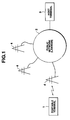
- FIG. 1 is a view showing the system configuration of this embodiment.
- a system for analyzing the action of a user having a portable terminal 1 in a host terminal (server machine) 3 accommodated in a public network 2 will be described. Assume that the user is always carrying the portable terminal 1.
- the portable terminal 1 detects the position (e.g., aa°bb' north and cc°dd' east) of the portable terminal 1 at a certain time point and this time autonomously or in accordance with an instruction from the portable terminal 1 and supplies the position and time information to the host terminal 3. At this time, the portable terminal 1 is connected to the public network 2 through the nearest base station 4. Upon being notified of the position and time, the host terminal 3 recognizes the position of the user who is carrying the portable terminal 1 at the certain time.
- the position e.g., aa°bb' north and cc°dd' east
- the portable terminal 1 supplies the information (position information and time information) to the host terminal 3 at every predetermined timing.
- the host terminal 3 analyzes the time-serially detected information, thereby recognizing the moving locus and the moving speed of the user of the portable terminal 1.
- FIG. 2 is a perspective view showing the outer appearance of the portable terminal 1.
- the portable terminal 1 has an LCD display unit 11, a microphone 12, and a general-purpose IF connector 13.
- a GPS (Global Positioning System) sensor 14 is connected to the general-purpose IF connector 13.
- the portable terminal 1 has a radio communication antenna 15.
- FIG. 3 is a block diagram of the portable terminal 1.
- a CPU 21 executes a program stored in a storage unit 22 (ROM and RAM).
- the CPU 21 and the storage unit 22 are connected via a bus 23.
- the storage unit 22 is constituted by a semiconductor memory, a magnetic recording medium, or an optical recording medium and stores the program, data, and the like.
- the storage unit 22 may be permanently incorporated or detachably mounted in the portable terminal 1.
- a recording medium driver 24 is connected to the bus 23 to read out data stored in a portable recording medium (including a semiconductor memory, a magnetic disk, an optical disk, and a magnetooptical disk) 25 or write data in the portable recording medium 25.
- a portable recording medium including a semiconductor memory, a magnetic disk, an optical disk, and a magnetooptical disk
- An IC card is assumed as an example of the portable recording medium 25.
- the CPU 21 can also execute a program stored in the portable recording medium 25.
- the program and data to be recorded in the storage unit 22 may be received from another device connected through a communication line or the like, and recorded.
- the CPU 21 may use, through the communication line or the like, a program and data stored in a storage unit arranged on the another device side.
- a unit corresponding to the LCD display unit 11 comprises a liquid crystal display (LCD) 31, a memory 32 for storing information to be displayed on the liquid crystal display 31, an LCD driver 33 for outputting information stored in the memory 32 to the liquid crystal display 31 under the control of an LCD control unit 34, and the LCD control unit 34 for controlling the memory 32 and the LCD driver 33.
- LCD liquid crystal display
- memory 32 for storing information to be displayed on the liquid crystal display
- LCD driver 33 for outputting information stored in the memory 32 to the liquid crystal display 31 under the control of an LCD control unit 34
- the LCD control unit 34 for controlling the memory 32 and the LCD driver 33.
- An A/D converter 35 converts sound information acquired through the microphone 12 into digital data.
- a sound information control unit 36 outputs the sound information A/D-converted by the A/D converter 35 to the bus 23.
- the sound information control unit 36 has a function of compressing sound information.
- the GPS sensor 14 detects the current position by communicating with, e.g., an artificial satellite.
- a general-purpose IF unit 37 outputs detected data from the GPS sensor 14 to the bus 23 in accordance with an instruction from the CPU 21.
- a timepiece 38 counts time.
- a timer 39 interrupts the CPU 21 at a predetermined time interval.
- a communication control unit 40 In sending data, a communication control unit 40 prepares a transmission packet and transfers the packet to a radio transceiver 41 in accordance with an instruction from the CPU 21. In receiving data, the communication control unit 40 outputs data stored in a packet received through the radio transceiver 41 onto the bus 23.
- the radio transceiver 41 is connected to the radio communication antenna 15 shown in FIG. 2 to transmit/receive data to/from the base station 4.
- FIG. 4 is a view showing the structure of a packet sent from the portable terminal 1.
- Each packet is constituted by a header portion and a data portion.
- the header portion stores a transmission source address, a transmission destination address, and the like.
- the address system containing an address to be stored as a transmission source address or a transmission destination address is determined depending on the network structure to which this embodiment is applied. In, e.g., TCP/IP communication, an IP address is stored.
- the data portion stores application identification information, a command, position information, time information, and sound information.
- the application identification information is used to identify an application program to be started on a destination terminal (host terminal 3 in this embodiment). In this embodiment, information for identifying an action analysis program is set. Note that, in TCP/IP communication, the application identification information is designated as a port number.
- the command is instruction information for the terminal (host terminal 3) designated by the transmission destination address and is interpreted on an application designated by application identification information.
- an action analysis command or an analysis result request command is used.
- the position information represents the position of the portable terminal 1 and corresponds to the position of the user who is carrying the portable terminal. This position information is sequentially prepared on the basis of the output from the GPS sensor 14.
- the time information represents time when the position information, i.e., the output from the GPS sensor 14 is detected, and corresponds to the output from the timepiece 38.
- the sound information is sound data acquired through the microphone 12 at the timing when the position information is detected. In this embodiment, sound information is acquired as ambient information of the portable terminal 1.
- a temperature sensor or a camera may be arranged to acquire temperature or image information as ambient information.
- FIG. 5 is a flow chart of an operation of preparing a packet from data acquired by the portable terminal and sending the packet.
- the program for realizing the functions of this flow chart is stored in the storage unit 22 as a form of program code which can be read by the CPU 21.
- the portable terminal 1 acquires position information, time information, and sound information N times at a predetermined time interval, transfers all the acquired information to the host terminal 3, and requests action analysis processing. Assume that the portable terminal 1 is always executing the program for acquiring position information, time information, and sound information while the power is ON.
- steps S1 and S2 predetermined time interval data is set for the timer 39, and the timer 39 is started.
- a predetermined time e.g., one minute
- an interrupt signal is input to the CPU 21 via the bus 23, so that processing from step S3 is executed.
- step S3 the output (position information) from the GPS sensor 14 is acquired.
- step S4 the time (time information) counted by the timepiece 38 is acquired.
- step S5 the timer 39 is reset.
- step S6 ambient sound data (e.g., noise) collected through the microphone 12 is acquired. This sound collection processing is performed for, e.g., 5 seconds.
- the timer 39 is reset and starts the time counting operation again.
- step S7 the information acquired in steps S3, S4, and S6 are temporarily held in the RAM in the storage unit 22.
- step S8 a counter (not shown) is incremented by one.
- step S9 the count value of the counter is checked. If the count value has reached "N (N: positive integer)", the flow advances to step S10. If the count value has not reached N, the flow returns to step S2 (to wait for the next interrupt signal from the timer 39). In step S10, the count value of the counter is cleared.
- step S11 the packet shown in FIG. 4 is prepared.
- the addresses of the portable terminal 1 and the host terminal 3 are set as a transmission source address and a transmission destination address, respectively.
- an "action analysis program” and an “action analysis command” are set.
- position information, time information, and sound information the pieces of information acquired in steps S3, S4, and S6 are read out from the storage unit 22 and stored in the packet.
- the position information, time information, and sound information to be stored are data acquired N times.
- step S12 the packet prepared in step S11 is output by radio. The packet is transferred to the host terminal 3 in accordance with the transmission destination address set in the header portion.
- all the acquired data corresponding to N cycles are transferred from the portable terminal 1 to the host terminal 3 to reduce the transmission cost.
- the data may be transferred when the acquired data reaches a predetermined capacity.
- position information, time information, or sound information may be transferred to the host terminal 3 every time the information is acquired.
- the flow chart shown in FIG. 5 is autonomously executed by the portable terminal 1.
- the processing of transmitting the packet to the host side may be executed in accordance with a starting instruction which is regularly transmitted from the host terminal 3.
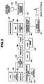
- FIG. 6 is a block diagram of the host terminal 3.
- a storage unit 51 is constituted by a semiconductor memory, a magnetic recording medium, or an optical recording medium and stores a program, data, and the like.
- the storage unit 51 may be permanently incorporated or detachably mounted in the host terminal 3.
- a recording medium driver 52 reads out data stored in a portable recording medium (including a semiconductor memory, a magnetic disk, an optical disk, and a magnetooptical disk) 53 or writes data in the portable recording medium 53.
- a communication control unit 54 controls data transmission/reception to/from the network. Packet transmission/reception to/from each portable terminal is also controlled by the communication control unit 54.
- a CPU 55 loads the program from the storage unit 51 or the portable recording medium 53 and executes the program.
- the program and data recorded in the storage unit 51 may be written from the portable recording medium 53 or received from another device on the network through the communication line or the like and recorded.
- the CPU 55 may use a program and data stored in another storage unit arranged on the network through the communication line or the like.
- FIG. 7 is a flow chart for explaining processing in the host terminal 3.
- a packet sent from the portable terminal 1 (packet prepared with processing of the flow chart shown in FIG. 5) is received to analyze the action of the user who is carrying the portable terminal 1.
- step S21 the transmission source address stored in the header portion of the received packet is checked to recognize the transmission terminal.
- the transmission terminal is assumed to be the portable terminal 1.
- the application identification information and the command are checked. In this case, assume that an "action analysis program” and an “action analysis command” are set.
- step S22 position information and time information, which are stored in the data portion of the received packet, are extracted to recognize the position (x i ,y i ) of the portable terminal 1 at time T i .
- step S23 the moving direction and moving speed of the portable terminal 1 from time T i-1 to time T i are calculated.
- step S24 the calculation result obtained in step S23 is used to estimate the moving means (walking, train, motor vehicle, stop, ⁇ ) of the user who is carrying the portable terminal 1. More specifically, the position of the user who is carrying the portable terminal 1 at a certain time point, and if he/she is moving, the moving means are estimated. In this processing of estimating the moving means, sound information stored in the data portion of the received packet is used, as needed.
- step S25 the estimation result obtained in step S24 is stored in the personal action file of the user who is carrying the portable terminal 1.
- the portable terminal 1 Upon receiving an action recording start command from a key input means (not shown) of the portable terminal 1, or the host terminal 3, the portable terminal 1 executes the processing of the flow chart shown in FIG. 5 and detects the output from the GPS sensor 14 at time T 0 , T 1 , T 2 , ⁇ , T 10 .
- the detected pieces of position information correspond to position data P 0 , P 1 , P 2 , ⁇ , P 10 .
- the portable terminal 1 fetches sound information acquired through the microphone 12. For example, it is estimated that, in a station, various types of noise are detected, and in a train, sounds unique to the train are detected.
- the portable terminal 1 transfers the detected position information, time information, and sound information to the host terminal 3. Since the data detected by the GPS sensor 14 have errors, points designated by the position information (position data P 0 , P 1 , P 2 , ⁇ , P 10 ) do not always match the line.
- the host terminal 3 Upon receiving the information transferred from the portable terminal 1, the host terminal 3 executes the processing of the flow chart shown in FIG. 7 to analyze the moving route of the user who is carrying the portable terminal 1. For the purpose of analyzing the route, the host terminal 3 has map data as shown in FIG. 9.
- FIG. 9 shows part of the position information of the line of A railway (position information of the line between station A and station B) as an example.
- pieces of information representing the positions of stations are stored.
- the position information of the line is stored as approximate curves of the line.
- the line between station A and station B is divided into four sections, and an approximate curve equation is defined for each section.
- the host terminal 3 also stores map data associated with all railways. Not only data associated with railways but also data associated with roads are stored in the host terminal 3. These map data are stored in, e.g., the storage unit 51 and loaded in the memory 56 as a reference, as needed.
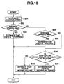
- FIG. 10 is a flow chart (1) for explaining processing of estimating the action of the user who is carrying the portable terminal 1. This processing corresponds to steps S23 and S24 in FIG. 7.
- step S31 the average moving speed of the user who is carrying the portable terminal 1 is calculated. More specifically, the average moving speed of the portable terminal 1 from time T i-1 to time T i is calculated according to the following formula. At this time, the moving direction is simultaneously calculated: (x i - x i -1 ) 2 + (y i - y i -1 ) 2
- the moving direction is simultaneously calculated: (x i - x i -1 ) 2 + (y i - y i -1 ) 2
- step S32 it is checked whether the speed calculated in step S31 is 1 km/h or less. If YES in step S32, it is estimated in step S33 that the user is "stopping". If NO in step S32, the flow advances to step S34.
- step S34 it is checked whether the speed calculated in step S31 is 6 km/h or less. If YES in step S34, it is estimated in step S35 that the user is "walking". If NO in step S34, the flow advances to step S36.
- step S36 it is checked whether the moving locus of the user who is carrying the portable terminal 1 is similar to the railway line pattern stored as map data.
- distances from the points designated by position data P 0 , P 1 , P 2 , ⁇ , P 10 to the curves represented by the curve equation representing the railway line are calculated by, e.g., the method of least squares, and determination is made on the basis of whether each calculated value is equal to or smaller than a predetermined value.
- determination is made on the basis of the similarity between a locus drawn by at least two position data and a curve pattern representing the railway line. Determination in this step is performed using a known technique, and a detailed description thereof will be omitted.
- step S37 If the moving locus of the user who is carrying the portable terminal 1 is similar to the line pattern, it is estimated in step S37 that the user is “moving by train”. If the moving locus is not similar to the line pattern, it is estimated in step S38 that the user is "moving by motor vehicle (automobile or bus)”.
- the estimation result obtained in this way is held in a predetermined area on the memory 56 as data of action (movement situation) of the user who is carrying the portable terminal 1 at a certain time point.
- the host terminal 3 sequentially stores the estimation result data at each time (time when the position information and the like are detected by the portable terminal 1).
- FIG. 11 is a flow chart (2) for explaining processing of estimating the action of the user who is carrying the portable terminal 1. This processing corresponds to step S24 in FIG. 7 and is executed parallel to the processing shown in FIG. 10.
- step S41 sound information stored in the packet transferred from the portable terminal 1 is extracted.
- step S42 the sound information is analyzed to recognize the characteristic features of the sound information.
- step S43 it is checked whether the sound information analyzed in step S42 includes unique sounds generated in a running train. If YES in step S43, it is estimated in step S44 that the user is "moving by train”. If NO in step S43, the flow advances to step S45.
- step S45 it is checked whether the sound information analyzed in step S42 includes unique sounds generated in a running motor vehicle or bus. If YES in step S45, it is estimated in step S46 that the user is "moving by motor vehicle”. If NO in step S45, the sound information is discarded in this estimation processing.
- the host terminal 3 holds in advance a unique sound pattern generated in a running train and a unique sound pattern generated in a running automobile or bus.
- step S43 or S45 the similarity between the sound information extracted in step S41 and the held pattern is determined.
- the estimation result obtained by processing of the flow chart shown in FIG. 11 is used as information for increasing the likelihood ratio of the estimation result obtained by processing of the flow chart shown in FIG. 10.
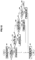
- FIG. 12 is a flow chart (3) for explaining processing of estimating the action of the user who is carrying the portable terminal 1.
- this processing a plurality of estimation results are obtained by processing of the flow charts shown in FIGS. 10 and 11, and the action of the user who is carrying the portable terminal 1 is estimated at a higher likelihood ratio on the basis of these pieces of information.
- step S51 M estimation results obtained by processing of the flow charts shown in FIGS. 10 and 11 are extracted.
- M 5
- estimation results at time T i-2 , T i-1 , T i , T i+1 , and T i+2 are extracted.
- step S52 it is checked whether all the M estimation results extracted in step S51 are in the same state. If YES In step S52, the estimation results are regarded as an estimation result having a higher likelihood ratio.
- the flow advances to step S61 to hold the result together with the position information and the time information. Assume that all the estimation results obtained by processing of the flow chart shown in FIG. 10 at times T i-2 , T i-1 , T i , T i+1 , and T i+2 are "stop", the host terminal 3 estimates that the user who is carrying the portable terminal 1 is stopping at the position represented by the position information at that time, and stores the estimation result in the memory 56 or the storage unit 51.
- step S52 If it is determined in step S52 that the estimation results are different, it is checked in step S54 whether the M estimation results include only "stop” and "walking". If YES in step S54, it is estimated in step S55 that the user who is carrying the portable terminal 1 is "walking". The flow advances to step S61 to hold the estimation result together with the position information and the time information.
- step S54 If, in step S54, the estimation results include estimation results other than "stop” and "walking", it is checked in step S56 whether a predetermined number or more of estimation results "moving by train” are included. If YES in step S56, it is estimated in step S57 that the user who is carrying the portable terminal 1 is "moving by train”. The flow advances to step S61 to hold the estimation result together with the position information and the time information.
- step S58 If NO in step S56, it is checked in step S58 whether "moving by motor vehicle (automobile or bus)" is included. If YES in step S58, it is estimated in step S59 that the user who is carrying the portable terminal 1 is "moving by motor vehicle". The flow advances to step S61 to hold the estimation result together with the position information and the time information. If NO in step S58, error processing is executed in step S60.
- the algorithm for estimating the action of the user who is carrying the portable terminal 1 is not limited to the above algorithm, and another method may be used.
- FIG. 15 is a flow chart of processing of preparing the action record table of the user who is carrying the portable terminal 1.
- step S71 "stop” is extracted from the estimation results shown in FIG. 13, and the start time and end time are checked. The position information is also extracted.
- step S72 it is checked whether the stop position extracted in step S71 is a position registered in advance.
- the host terminal 3 refers to a table shown in FIG. 16.
- the table shown in FIG. 16 stores various names on the map and corresponding position information. Railway stations and other public facilities are registered in advance. In addition, the user can register a desired location. In this embodiment, "head office”, “business office”, “Mr. K's house”, are registered.
- step S72 the name of the registration position is extracted in step S73. If NO in step S72, the region name of the position (e.g., xx Prefecture xx City xx) is extracted in step S74. Note that the host terminal 3 has a table storing region names and corresponding position information.
- step S75 the registration position name extracted in step S73 or the region name extracted in step S74 is written for the time zone of "stop" recognized in step S71.
- the position information detected by the portable terminal 1 before 14:10 must be equal or approximate to position data (x 501 ,y 501 ) registered in the table shown in FIG. 16.
- the position information detected by the portable terminal 1 is transferred to the host terminal 3 and stored in the table shown in FIG. 13.
- the host terminal 3 recognizes that the user who was carrying the portable terminal was in the head office before 14:10 because the position information detected by the portable terminal 1 is equal or approximate to the position data registered as the position of the head office. As a result, "head office" is written for the time zone before 14:10, as shown in FIG. 14.
- step S76 the moving means (walking, train, automobile, or bus) represented by the above-described estimation result and the start time and end time of movement using the moving means are checked. As shown in FIG. 14, the moving means is written for each time zone. When a specific means of transportation is used, the means of transportation is written in step S77. Assume that it is estimated from the similarity to the railway line pattern stored as map data shown in FIG. 9 that the user who was carrying the portable terminal moved from station A to station B by A railway, "A railway” is written as a moving means, and region names "station A" and "station B" are written as a starting point and a terminal point, respectively.
- the action record table prepared in the above way is stored in a predetermined area in the storage unit 51 of the host terminal 3.
- a packet for requesting display of the action record table is sent from the portable terminal 1.
- the request packet has the structure shown in FIG. 4.
- the addresses of the portable terminal 1 and the host terminal 3 are set as a transmission source address and a transmission destination address, respectively.
- An "action analysis program” is set as application identification information, and an “analysis result request command” is set as a command.
- a date to be referred to is added as additional information of the command.
- the command and the additional information of the command are input by the user using, e.g., a pen input method from the LCD display unit 11 of the portable terminal 1.
- the host terminal 3 Upon receiving the command having the "analysis result request command" from the portable terminal 1, the host terminal 3 interprets the command and extracts the action record table of the user who is carrying the portable terminal 1 at the designated date. The extracted action record table is stored in a packet and transferred to the portable terminal 1. The portable terminal 1 extracts the action record table from the packet transferred from the host terminal 3 and displays it on the LCD display unit 11.
- the processing programs executed by the host terminal 3, i.e., programs for realizing the functions of the flow charts shown in FIGS. 7, 10, 11, 12, and 15, and the program for interpreting a command transferred from the portable terminal 1 and processing the command are stored in the storage unit 51 or the portable recording medium 53 in the form of program codes which can be read by the CPU 55. Alternatively, programs stored in another device connected through the network are used.
- the portable terminal 1 need have only a function of detecting position information and time information and transferring them to the host terminal 3, a function of requesting the host terminal 3 of an action record, and a function of displaying data downloaded from the host terminal 3. That is, the portable terminal 1 need neither store an enormous quantity of map data nor execute highly precise pattern recognition processing or various processing which require high-speed processing. For this reason, the portable terminal 1 can obtain an advanced action analysis result without requiring any large-capacity memory or high-performance processor.
- position information and time information are detected by the portable terminal 1 at a predetermined timing.
- the present invention is not limited to this arrangement.
- the user of the movable terminal is not always moving and can be considered to stop at a certain position for most of time. If the user of the portable terminal stops at a certain position for a predetermined time or more, position information need not be detected every predetermined time, and not all the position information need be supplied from the portable terminal 1 to the host terminal 3.
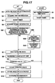
- FIG. 17 is a flow chart showing an operation of preparing a packet from data acquired by the portable terminal 1 and sending the packet. This processing procedure is obtained by adding steps S81 through S83 to the flow chart shown in FIG. 5.
- step S81 it is checked whether the position information obtained in step S3 coincides with position information of one and two cycles before. If NO in step S81, the flow advances to step S7 to continue the processing in FIG. 5. If YES in step S81, the position information, time information, and sound information at the preceding timing are discarded in step S82. In step S83, the counter which is to be incremented by one in step S8 is decremented by one.
- step S7 "Position P 0" is detected by position detection at time T 1 and time T 2 , and these data are held in step S7.
- step S 3 "position P 0 " is detected again.
- step S81 the position data at time T 3 coincides with position data of one (time T 2 ) and two (time T 1 ) cycles before.
- step S82 the position data at time T 3 is held in step S7. As a result, only the pieces of information acquired at time T 1 and time T 3 are held.
- step S81 position data at time T 4 coincides with position data of one (time T 3 ) and two (time T 1 ) cycles before
- step S82 to discard position information, time information, and sound information acquired at the preceding timing (time T 3 ).
- time T 2 corresponds to the timing of "two cycles before”.
- step S7 the position data at time T 4 is held in step S7. As a result, only the pieces of information acquired at time T 1 and time T 4 are held.
- the GPS sensor is used as a means for detecting the position information of the portable terminal 1.
- the present invention is not limited to this.
- a cell which is currently managing the portable terminal may be used as position information.
- the action record table has the form of a timing chart as shown in FIG. 14.
- the present invention is not limited to this.
- an illustration as shown in FIG. 18 may be used.
- position information or time information is detected at a predetermined time interval.
- information need not always be detected at a predetermined time interval.
- Information may be appropriately sampled a sufficient number of times for action analysis.
- the action of the user who is carrying the movable terminal is analyzed.
- the arrangement is not limited to the application purpose of detecting the human action.
- the arrangement can also be applied to survey the action pattern of an animal or check the delivery state of goods.
Abstract
Description
Claims (8)
- An action analyzing/recording system characterized in that information transmitted through a communication control unit of a terminal (1) is analyzed by an information processing unit connected to a network (2) as an action record, data of an analysis result is stored in correspondence with a terminal identification code, and the data is transferred to said terminal as needed, said terminal comprising a detector (14) for detecting position information and time information, and said communication control unit (40) for network connection, and transmitting the information detected by said detector together with the terminal identification code.
- A system according to claim 1, characterized in that said terminal accumulates the detected information, and after the information has reached a predetermined number or predetermined capacity, transmits the accumulated information at once.
- A system according to claim 1, characterized in that when position information representing that said terminal stays at a certain position is detected, said terminal is controlled not to transmit information twice.
- A system according to claim 1, characterized in that said information processing unit has means (51) for storing map information representing a transport route including a railway line, specifies information of a place of movement on the basis of the map information and the position and time information transmitted from said terminal, and stores the place information together with time.
- A system according to claim 1, characterized in that said information processing unit calculates a moving speed from the position and time information transmitted from said terminal to estimate a moving means.
- A system according to claim 5, characterized by further comprising means for detecting ambient information including sound information, and wherein said estimating means specifies the action route in consideration of the detected ambient information.
- A system according to claim 5, wherein said information processing unit has means (51) for storing map information representing a transport route including a railway line and specifies a name of a transport facility on the basis of the map information and the analyzed moving means.
- An action analyzing/recording system comprising:means (14) for detecting position information and time information of a terminal;means (3, FIGS. 10 and 11) for analyzing a moving locus and a moving speed of said terminal on the basis of the detected position and time information;means (3, FIG. 12) for estimating an action route on the basis of the analyzed data; andmeans (3, FIG. 15) for storing, on the basis of the estimated action route, information of a place and time of action as an action record.
Applications Claiming Priority (3)
| Application Number | Priority Date | Filing Date | Title |
|---|---|---|---|
| JP26641296A JP3252721B2 (en) | 1996-10-07 | 1996-10-07 | Behavior analysis device |
| JP266412/96 | 1996-10-07 | ||
| JP26641296 | 1996-10-07 |
Publications (2)
| Publication Number | Publication Date |
|---|---|
| EP0834840A1 true EP0834840A1 (en) | 1998-04-08 |
| EP0834840B1 EP0834840B1 (en) | 2002-06-19 |
Family
ID=17430582
Family Applications (1)
| Application Number | Title | Priority Date | Filing Date |
|---|---|---|---|
| EP97116972A Expired - Lifetime EP0834840B1 (en) | 1996-10-07 | 1997-09-30 | Action analyzing/recording system |
Country Status (4)
| Country | Link |
|---|---|
| US (1) | US6195022B1 (en) |
| EP (1) | EP0834840B1 (en) |
| JP (1) | JP3252721B2 (en) |
| DE (1) | DE69713466D1 (en) |
Cited By (15)
| Publication number | Priority date | Publication date | Assignee | Title |
|---|---|---|---|---|
| WO2002009042A1 (en) * | 2000-07-20 | 2002-01-31 | Joint Stock Company 'general Technologys' | Method for collecting and analysing working conditions of television receivers, video recorders radio receivers and other widely used appliances and system for carrying out said method |
| WO2002091232A2 (en) * | 2001-05-03 | 2002-11-14 | International Business Machines Corporation | Method, system, and program for querying data in a personal information manager database |
| FR2838854A1 (en) * | 2002-04-18 | 2003-10-24 | Pierre Georges Herve | Individual checking or tally device for use as a clocking-in system in a workplace environment, whereby individuals are equipped with the device that includes a GPS receiver so that their location can be accurately determined |
| US6873851B2 (en) | 2001-05-03 | 2005-03-29 | International Business Machines Corporation | Method, system, and program for providing user location information for a personal information management system from transmitting devices |
| US7085818B2 (en) | 2001-09-27 | 2006-08-01 | International Business Machines Corporation | Method, system, and program for providing information on proximate events based on current location and user availability |
| US7248872B2 (en) | 2002-01-08 | 2007-07-24 | International Business Machines Corporation | Method, system, and program for providing information on users of wireless devices in a database to a personal information manager |
| US7340691B2 (en) | 2001-06-25 | 2008-03-04 | International Business Machines Corporation | Method, system, and program for accessing calendar information for shadowed users from a database |
| US7370085B2 (en) | 2001-05-03 | 2008-05-06 | International Business Machines Corporation | Method, system, and program for providing user location information with a personal information management program |
| US7562043B2 (en) | 2001-06-29 | 2009-07-14 | International Business Machines Corporation | Method, system, and program for implementing an auction using calendar information |
| WO2010049747A1 (en) * | 2008-10-29 | 2010-05-06 | Telefonaktiebolaget Lm Ericsson (Publ) | Personal task planning with automatic task discovery |
| WO2012129327A3 (en) * | 2011-03-21 | 2012-11-29 | Trucktrax, Llc | Tracking and management system |
| US20140101169A1 (en) * | 2011-06-13 | 2014-04-10 | Sony Corporation | Information processing device, information processing method, and computer program |
| US8818380B2 (en) | 2004-07-09 | 2014-08-26 | Israel Feldman | System and method for geographically locating a cellular phone |
| US9418545B2 (en) | 2011-06-29 | 2016-08-16 | Inrix Holding Limited | Method and system for collecting traffic data |
| US9798985B2 (en) | 2009-02-02 | 2017-10-24 | Inrix Holdings Limited | Apparatus and methods for providing journey information |
Families Citing this family (45)
| Publication number | Priority date | Publication date | Assignee | Title |
|---|---|---|---|---|
| JP3399281B2 (en) * | 1997-03-17 | 2003-04-21 | カシオ計算機株式会社 | Daily report creation system |
| US6560461B1 (en) | 1997-08-04 | 2003-05-06 | Mundi Fomukong | Authorized location reporting paging system |
| US6381533B1 (en) * | 1997-10-16 | 2002-04-30 | Navigation Technologies Corp. | Method and system using positions of cellular phones matched to road network for collecting data |
| JP3298484B2 (en) * | 1997-12-24 | 2002-07-02 | カシオ計算機株式会社 | Information transmission device |
| US6194038B1 (en) | 1998-03-20 | 2001-02-27 | Applied Materials, Inc. | Method for deposition of a conformal layer on a substrate |
| JP2000193483A (en) * | 1998-10-22 | 2000-07-14 | Seiko Instruments Inc | Portable gps receiver |
| JP2000193482A (en) * | 1998-10-22 | 2000-07-14 | Seiko Instruments Inc | Portable gps speed/distance meter |
| JP3378514B2 (en) * | 1998-10-28 | 2003-02-17 | 株式会社東芝 | Information processing apparatus, communication system, and information processing method |
| JP3488104B2 (en) * | 1998-11-18 | 2004-01-19 | 富士通株式会社 | Mobile object characteristic extraction device, characteristic extraction method, and program recording medium therefor |
| DE19935645A1 (en) * | 1999-07-29 | 2001-02-01 | Bosch Gmbh Robert | Navigation method and navigation device |
| US6341255B1 (en) | 1999-09-27 | 2002-01-22 | Decell, Inc. | Apparatus and methods for providing route guidance to vehicles |
| JP3767671B2 (en) * | 1999-10-08 | 2006-04-19 | アイシン・エィ・ダブリュ株式会社 | Navigation device and navigation method |
| JP3545666B2 (en) * | 2000-02-14 | 2004-07-21 | 株式会社東芝 | Service providing system for mobile terminals |
| JP3700024B2 (en) * | 2000-04-07 | 2005-09-28 | 日本電信電話株式会社 | Information notification network device, information notification method, and recording medium recording information notification method processing program |
| CN1533537A (en) * | 2000-06-16 | 2004-09-29 | Display facility supplementing experience of visitor | |
| JP2002073749A (en) * | 2000-08-28 | 2002-03-12 | Matsushita Electric Works Ltd | Operation process analysis support system |
| US6587781B2 (en) | 2000-08-28 | 2003-07-01 | Estimotion, Inc. | Method and system for modeling and processing vehicular traffic data and information and applying thereof |
| JP2002092253A (en) * | 2000-09-12 | 2002-03-29 | Mitsubishi Electric Corp | Behavior pattern gathering system and behavior pattern gathering method |
| JP2002133053A (en) * | 2000-10-23 | 2002-05-10 | Nec Commun Syst Ltd | Path search system |
| JP4550304B2 (en) * | 2001-03-21 | 2010-09-22 | 株式会社富士通ソーシアルサイエンスラボラトリ | POSITION INFORMATION PROVIDING SYSTEM, POSITION INFORMATION PROVIDING SYSTEM OPERATION DEVICE, POSITION INFORMATION PROVIDING DEVICE, OPERATING DEVICE PROGRAM, AND POSITION INFORMATION PROVIDING DEVICE PROGRAM |
| JP4117126B2 (en) * | 2001-11-30 | 2008-07-16 | 株式会社日立製作所 | Handling support method |
| JP3867696B2 (en) * | 2003-10-06 | 2007-01-10 | 住友電気工業株式会社 | Moving means discriminating apparatus and method, and OD traffic volume calculating apparatus and method |
| TWI263443B (en) * | 2004-09-29 | 2006-10-01 | Benq Corp | Urgent contact apparatus and method for mobile communication |
| JP2006352626A (en) * | 2005-06-17 | 2006-12-28 | Nippon Telegr & Teleph Corp <Ntt> | Moving locus analyzing device and program |
| JP2007257086A (en) | 2006-03-20 | 2007-10-04 | Fujitsu Ltd | Action recording support program, system, device and method |
| JP4825050B2 (en) * | 2006-05-12 | 2011-11-30 | ヤフー株式会社 | Method and system for obtaining moving means from position information |
| JP4861154B2 (en) * | 2006-12-19 | 2012-01-25 | 株式会社エヌ・ティ・ティ・ドコモ | Information service providing system, target behavior estimation device, target behavior estimation method |
| CN101094525B (en) * | 2007-07-26 | 2010-06-02 | 华为技术有限公司 | Method and device for generating user's attribute information |
| JP5208637B2 (en) * | 2008-09-16 | 2013-06-12 | 株式会社東芝 | Information processing apparatus, method, and program |
| US20110137836A1 (en) * | 2008-09-19 | 2011-06-09 | Hiroyuki Kuriyama | Method and system for generating history of behavior |
| JP5193808B2 (en) * | 2008-11-04 | 2013-05-08 | 日本電信電話株式会社 | Determination device, determination method, determination program and recording medium for moving means |
| JP5499342B2 (en) * | 2008-11-28 | 2014-05-21 | 株式会社日立製作所 | Sensor node, sensor network system, and data collection method |
| WO2010119926A1 (en) * | 2009-04-17 | 2010-10-21 | 株式会社エヌ・ティ・ティ・ドコモ | Taxi user extraction device, taxi user extraction method, transportation user extraction device, and transportation user extraction method |
| US20110022443A1 (en) * | 2009-07-21 | 2011-01-27 | Palo Alto Research Center Incorporated | Employment inference from mobile device data |
| JP2011119990A (en) * | 2009-12-03 | 2011-06-16 | Zenrin Datacom Co Ltd | Probe information collection system, probe information collection method, and program |
| JP5086388B2 (en) * | 2010-04-19 | 2012-11-28 | 株式会社富士通ソーシアルサイエンスラボラトリ | POSITION INFORMATION PROVIDING DEVICE AND POSITION INFORMATION PROVIDING DEVICE PROGRAM |
| JP5803148B2 (en) * | 2011-02-28 | 2015-11-04 | セイコーエプソン株式会社 | Document information recording apparatus, document information recording method, document information recording program, and document information recording system |
| JP5826049B2 (en) * | 2012-01-20 | 2015-12-02 | Kddi株式会社 | Moving vehicle estimation method, mobile terminal, and program for estimating moving vehicle on which user is on board |
| CN102595317B (en) * | 2012-02-27 | 2015-11-18 | 歌尔声学股份有限公司 | A kind of communication signal self-adapting transmission method and system |
| JP5901392B2 (en) * | 2012-03-30 | 2016-04-06 | 株式会社ゼンリンデータコム | Information processing system and information processing method |
| JP5904021B2 (en) * | 2012-06-07 | 2016-04-13 | ソニー株式会社 | Information processing apparatus, electronic device, information processing method, and program |
| JP6111752B2 (en) * | 2013-03-08 | 2017-04-12 | 大日本印刷株式会社 | Information processing device, information processing method, program for information processing device, information processing system, and terminal device |
| JP5855041B2 (en) * | 2013-03-28 | 2016-02-09 | 株式会社ぐるなび | Route determination system |
| JP6350251B2 (en) | 2014-12-04 | 2018-07-04 | 富士通株式会社 | Route information processing apparatus, method, and program |
| JP6686536B2 (en) * | 2016-03-02 | 2020-04-22 | 株式会社リコー | Information processing device and program |
Citations (6)
| Publication number | Priority date | Publication date | Assignee | Title |
|---|---|---|---|---|
| US4750197A (en) * | 1986-11-10 | 1988-06-07 | Denekamp Mark L | Integrated cargo security system |
| GB2271486A (en) * | 1992-10-07 | 1994-04-13 | Motorola Ltd | A cellular communications system employing GPS positioning |
| EP0637807A2 (en) * | 1993-07-26 | 1995-02-08 | Rank Xerox Limited | Recording and retrieval of information relevant to the activities of a user |
| US5473729A (en) * | 1992-09-30 | 1995-12-05 | Bryant; David P. | Critical incident recorder |
| JPH08122093A (en) * | 1994-10-13 | 1996-05-17 | Roehm Properties Bv | Portable position detector,daily-report prepairing device and travelling-expense liquidation-statement prepairing device |
| EP0720137A2 (en) * | 1994-12-28 | 1996-07-03 | Omron Corporation | Traffic information system |
Family Cites Families (6)
| Publication number | Priority date | Publication date | Assignee | Title |
|---|---|---|---|---|
| US5289183A (en) * | 1992-06-19 | 1994-02-22 | At/Comm Incorporated | Traffic monitoring and management method and apparatus |
| US5335664A (en) | 1991-09-17 | 1994-08-09 | Casio Computer Co., Ltd. | Monitor system and biological signal transmitter therefor |
| US5731785A (en) * | 1994-05-13 | 1998-03-24 | Lemelson; Jerome H. | System and method for locating objects including an inhibiting feature |
| US5543789A (en) * | 1994-06-24 | 1996-08-06 | Shields Enterprises, Inc. | Computerized navigation system |
| US5742666A (en) * | 1994-10-05 | 1998-04-21 | Tele Digital Development, Inc. | Emergency mobile telephone |
| US5774070A (en) * | 1995-11-22 | 1998-06-30 | Rendon; Edward | Method and system for the precise thermal mapping of roads, runways and the like for wintertime safety monitoring and maintenance |
-
1996
- 1996-10-07 JP JP26641296A patent/JP3252721B2/en not_active Expired - Fee Related
-
1997
- 1997-09-19 US US08/934,331 patent/US6195022B1/en not_active Expired - Lifetime
- 1997-09-30 EP EP97116972A patent/EP0834840B1/en not_active Expired - Lifetime
- 1997-09-30 DE DE69713466T patent/DE69713466D1/en not_active Expired - Lifetime
Patent Citations (6)
| Publication number | Priority date | Publication date | Assignee | Title |
|---|---|---|---|---|
| US4750197A (en) * | 1986-11-10 | 1988-06-07 | Denekamp Mark L | Integrated cargo security system |
| US5473729A (en) * | 1992-09-30 | 1995-12-05 | Bryant; David P. | Critical incident recorder |
| GB2271486A (en) * | 1992-10-07 | 1994-04-13 | Motorola Ltd | A cellular communications system employing GPS positioning |
| EP0637807A2 (en) * | 1993-07-26 | 1995-02-08 | Rank Xerox Limited | Recording and retrieval of information relevant to the activities of a user |
| JPH08122093A (en) * | 1994-10-13 | 1996-05-17 | Roehm Properties Bv | Portable position detector,daily-report prepairing device and travelling-expense liquidation-statement prepairing device |
| EP0720137A2 (en) * | 1994-12-28 | 1996-07-03 | Omron Corporation | Traffic information system |
Non-Patent Citations (1)
| Title |
|---|
| DATABASE WPI Section EI Week 9630, Derwent World Patents Index; Class S02, AN 96-290512, XP002052921 * |
Cited By (23)
| Publication number | Priority date | Publication date | Assignee | Title |
|---|---|---|---|---|
| WO2002009042A1 (en) * | 2000-07-20 | 2002-01-31 | Joint Stock Company 'general Technologys' | Method for collecting and analysing working conditions of television receivers, video recorders radio receivers and other widely used appliances and system for carrying out said method |
| WO2002091232A2 (en) * | 2001-05-03 | 2002-11-14 | International Business Machines Corporation | Method, system, and program for querying data in a personal information manager database |
| WO2002091232A3 (en) * | 2001-05-03 | 2003-04-24 | Ibm | Method, system, and program for querying data in a personal information manager database |
| US6751626B2 (en) | 2001-05-03 | 2004-06-15 | International Business Machines Corporation | Method, system, and program for mining data in a personal information manager database |
| US6873851B2 (en) | 2001-05-03 | 2005-03-29 | International Business Machines Corporation | Method, system, and program for providing user location information for a personal information management system from transmitting devices |
| US7370085B2 (en) | 2001-05-03 | 2008-05-06 | International Business Machines Corporation | Method, system, and program for providing user location information with a personal information management program |
| US7340691B2 (en) | 2001-06-25 | 2008-03-04 | International Business Machines Corporation | Method, system, and program for accessing calendar information for shadowed users from a database |
| US7562043B2 (en) | 2001-06-29 | 2009-07-14 | International Business Machines Corporation | Method, system, and program for implementing an auction using calendar information |
| US7085818B2 (en) | 2001-09-27 | 2006-08-01 | International Business Machines Corporation | Method, system, and program for providing information on proximate events based on current location and user availability |
| US7248872B2 (en) | 2002-01-08 | 2007-07-24 | International Business Machines Corporation | Method, system, and program for providing information on users of wireless devices in a database to a personal information manager |
| FR2838854A1 (en) * | 2002-04-18 | 2003-10-24 | Pierre Georges Herve | Individual checking or tally device for use as a clocking-in system in a workplace environment, whereby individuals are equipped with the device that includes a GPS receiver so that their location can be accurately determined |
| US8818380B2 (en) | 2004-07-09 | 2014-08-26 | Israel Feldman | System and method for geographically locating a cellular phone |
| US9155060B2 (en) | 2004-07-09 | 2015-10-06 | INRX Global Services Limited | System and method for geographically locating a cellular phone |
| US9026114B2 (en) | 2004-07-09 | 2015-05-05 | INRX Global Services Limited | System and method for geographically locating a cellular phone |
| WO2010049747A1 (en) * | 2008-10-29 | 2010-05-06 | Telefonaktiebolaget Lm Ericsson (Publ) | Personal task planning with automatic task discovery |
| US9798985B2 (en) | 2009-02-02 | 2017-10-24 | Inrix Holdings Limited | Apparatus and methods for providing journey information |
| WO2012129327A3 (en) * | 2011-03-21 | 2012-11-29 | Trucktrax, Llc | Tracking and management system |
| EP2720176A1 (en) * | 2011-06-13 | 2014-04-16 | Sony Corporation | Information processing device, information processing method, and computer program |
| EP2720176A4 (en) * | 2011-06-13 | 2014-12-10 | Sony Corp | Information processing device, information processing method, and computer program |
| US20140101169A1 (en) * | 2011-06-13 | 2014-04-10 | Sony Corporation | Information processing device, information processing method, and computer program |
| CN106202528A (en) * | 2011-06-13 | 2016-12-07 | 索尼公司 | Information processor, information processing method and computer program |
| US10740057B2 (en) | 2011-06-13 | 2020-08-11 | Sony Corporation | Information processing device, information processing method, and computer program |
| US9418545B2 (en) | 2011-06-29 | 2016-08-16 | Inrix Holding Limited | Method and system for collecting traffic data |
Also Published As
| Publication number | Publication date |
|---|---|
| JPH10111877A (en) | 1998-04-28 |
| JP3252721B2 (en) | 2002-02-04 |
| EP0834840B1 (en) | 2002-06-19 |
| DE69713466D1 (en) | 2002-07-25 |
| US6195022B1 (en) | 2001-02-27 |
Similar Documents
| Publication | Publication Date | Title |
|---|---|---|
| EP0834840A1 (en) | Action analyzing/recording system | |
| US7756529B2 (en) | Position information management method and apparatus | |
| US7176801B2 (en) | Article management system and method | |
| US7739033B2 (en) | Information processing device and method, program, and information processing system | |
| KR101015616B1 (en) | System and method for management of school bus | |
| EP1349363B1 (en) | Digital camera connected to a navigation device and to an external storage information system | |
| US7456871B2 (en) | Image management system managing image data obtained from an imaging device carried by a visitor to an area in a same manner as image data obtained from imagining devices fixed to particular locations in the area | |
| US6898434B2 (en) | Apparatus and method for the automatic positioning of information access points | |
| KR101147748B1 (en) | A mobile telecommunication device having a geographic information providing function and the method thereof | |
| EP1035531A3 (en) | Information providing system for mobile units | |
| EP1205733A2 (en) | Method and device for providing information related to activity of user | |
| EP1107534A3 (en) | Information storage system, server apparatus and information control method | |
| KR20080053134A (en) | Apparatus and method for reconizing a position using a camera | |
| US6859837B2 (en) | Service information providing method, service information providing apparatus and system | |
| JP2004252809A (en) | Method and system for guiding parking position in large parking lot | |
| CN106981192A (en) | The recognition methods of electronic map road conditions and system based on drive recorder | |
| CN106384530A (en) | Parking lot vehicle parking-searching system based on smartphone | |
| TW201903429A (en) | Position measuring terminal device, computer program and system | |
| EP1298622A3 (en) | Satellite navigation system for more personalized navigation | |
| JP2001175983A (en) | System and method for registering client data | |
| JP2002312381A (en) | Positional information system | |
| JP3706907B2 (en) | Method for estimating the current position and orientation of a user | |
| CN110044372A (en) | Vehicle carried device, server, navigation system, map display program and method | |
| JPH0728884A (en) | Portable terminal equipment, data base system, and image scanner | |
| CN110738771A (en) | cell map measuring method and system |
Legal Events
| Date | Code | Title | Description |
|---|---|---|---|
| PUAI | Public reference made under article 153(3) epc to a published international application that has entered the european phase |
Free format text: ORIGINAL CODE: 0009012 |
|
| 17P | Request for examination filed |
Effective date: 19970930 |
|
| AK | Designated contracting states |
Kind code of ref document: A1 Designated state(s): DE FR GB IT NL |
|
| RAP1 | Party data changed (applicant data changed or rights of an application transferred) |
Owner name: CASIO COMPUTER CO., LTD. |
|
| AKX | Designation fees paid |
Free format text: DE FR GB IT NL |
|
| RBV | Designated contracting states (corrected) |
Designated state(s): DE FR GB IT NL |
|
| 17Q | First examination report despatched |
Effective date: 19991102 |
|
| GRAG | Despatch of communication of intention to grant |
Free format text: ORIGINAL CODE: EPIDOS AGRA |
|
| GRAG | Despatch of communication of intention to grant |
Free format text: ORIGINAL CODE: EPIDOS AGRA |
|
| GRAH | Despatch of communication of intention to grant a patent |
Free format text: ORIGINAL CODE: EPIDOS IGRA |
|
| GRAH | Despatch of communication of intention to grant a patent |
Free format text: ORIGINAL CODE: EPIDOS IGRA |
|
| GRAA | (expected) grant |
Free format text: ORIGINAL CODE: 0009210 |
|
| RAP1 | Party data changed (applicant data changed or rights of an application transferred) |
Owner name: CASIO COMPUTER CO., LTD. |
|
| AK | Designated contracting states |
Kind code of ref document: B1 Designated state(s): DE FR GB IT NL |
|
| PG25 | Lapsed in a contracting state [announced via postgrant information from national office to epo] |
Ref country code: NL Free format text: LAPSE BECAUSE OF FAILURE TO SUBMIT A TRANSLATION OF THE DESCRIPTION OR TO PAY THE FEE WITHIN THE PRESCRIBED TIME-LIMIT Effective date: 20020619 Ref country code: IT Free format text: LAPSE BECAUSE OF FAILURE TO SUBMIT A TRANSLATION OF THE DESCRIPTION OR TO PAY THE FEE WITHIN THE PRESCRIBED TIME-LIMIT;WARNING: LAPSES OF ITALIAN PATENTS WITH EFFECTIVE DATE BEFORE 2007 MAY HAVE OCCURRED AT ANY TIME BEFORE 2007. THE CORRECT EFFECTIVE DATE MAY BE DIFFERENT FROM THE ONE RECORDED. Effective date: 20020619 |
|
| REG | Reference to a national code |
Ref country code: GB Ref legal event code: FG4D |
|
| REF | Corresponds to: |
Ref document number: 69713466 Country of ref document: DE Date of ref document: 20020725 |
|
| PG25 | Lapsed in a contracting state [announced via postgrant information from national office to epo] |
Ref country code: DE Free format text: LAPSE BECAUSE OF FAILURE TO SUBMIT A TRANSLATION OF THE DESCRIPTION OR TO PAY THE FEE WITHIN THE PRESCRIBED TIME-LIMIT Effective date: 20020920 |
|
| ET | Fr: translation filed | ||
| NLV1 | Nl: lapsed or annulled due to failure to fulfill the requirements of art. 29p and 29m of the patents act | ||
| PLBE | No opposition filed within time limit |
Free format text: ORIGINAL CODE: 0009261 |
|
| STAA | Information on the status of an ep patent application or granted ep patent |
Free format text: STATUS: NO OPPOSITION FILED WITHIN TIME LIMIT |
|
| 26N | No opposition filed |
Effective date: 20030320 |
|
| PGFP | Annual fee paid to national office [announced via postgrant information from national office to epo] |
Ref country code: GB Payment date: 20140919 Year of fee payment: 18 Ref country code: FR Payment date: 20140919 Year of fee payment: 18 |
|
| GBPC | Gb: european patent ceased through non-payment of renewal fee |
Effective date: 20150930 |
|
| REG | Reference to a national code |
Ref country code: FR Ref legal event code: ST Effective date: 20160531 |
|
| PG25 | Lapsed in a contracting state [announced via postgrant information from national office to epo] |
Ref country code: GB Free format text: LAPSE BECAUSE OF NON-PAYMENT OF DUE FEES Effective date: 20150930 |
|
| PG25 | Lapsed in a contracting state [announced via postgrant information from national office to epo] |
Ref country code: FR Free format text: LAPSE BECAUSE OF NON-PAYMENT OF DUE FEES Effective date: 20150930 |