EP0834286A1 - Apparatus for applying surgical clips - Google Patents
Apparatus for applying surgical clips Download PDFInfo
- Publication number
- EP0834286A1 EP0834286A1 EP97115934A EP97115934A EP0834286A1 EP 0834286 A1 EP0834286 A1 EP 0834286A1 EP 97115934 A EP97115934 A EP 97115934A EP 97115934 A EP97115934 A EP 97115934A EP 0834286 A1 EP0834286 A1 EP 0834286A1
- Authority
- EP
- European Patent Office
- Prior art keywords
- jaw
- actuator
- clip
- handle portion
- surgical
- Prior art date
- Legal status (The legal status is an assumption and is not a legal conclusion. Google has not performed a legal analysis and makes no representation as to the accuracy of the status listed.)
- Granted
Links
Images


Classifications
-
- A—HUMAN NECESSITIES
- A61—MEDICAL OR VETERINARY SCIENCE; HYGIENE
- A61B—DIAGNOSIS; SURGERY; IDENTIFICATION
- A61B17/00—Surgical instruments, devices or methods, e.g. tourniquets
- A61B17/12—Surgical instruments, devices or methods, e.g. tourniquets for ligaturing or otherwise compressing tubular parts of the body, e.g. blood vessels, umbilical cord
- A61B17/128—Surgical instruments, devices or methods, e.g. tourniquets for ligaturing or otherwise compressing tubular parts of the body, e.g. blood vessels, umbilical cord for applying or removing clamps or clips
- A61B17/1285—Surgical instruments, devices or methods, e.g. tourniquets for ligaturing or otherwise compressing tubular parts of the body, e.g. blood vessels, umbilical cord for applying or removing clamps or clips for minimally invasive surgery
-
- A—HUMAN NECESSITIES
- A61—MEDICAL OR VETERINARY SCIENCE; HYGIENE
- A61B—DIAGNOSIS; SURGERY; IDENTIFICATION
- A61B17/00—Surgical instruments, devices or methods, e.g. tourniquets
- A61B2017/00367—Details of actuation of instruments, e.g. relations between pushing buttons, or the like, and activation of the tool, working tip, or the like
- A61B2017/00407—Ratchet means
-
- A—HUMAN NECESSITIES
- A61—MEDICAL OR VETERINARY SCIENCE; HYGIENE
- A61B—DIAGNOSIS; SURGERY; IDENTIFICATION
- A61B17/00—Surgical instruments, devices or methods, e.g. tourniquets
- A61B17/28—Surgical forceps
- A61B17/2812—Surgical forceps with a single pivotal connection
- A61B17/2833—Locking means
- A61B2017/2837—Locking means with a locking ratchet
-
- A—HUMAN NECESSITIES
- A61—MEDICAL OR VETERINARY SCIENCE; HYGIENE
- A61B—DIAGNOSIS; SURGERY; IDENTIFICATION
- A61B17/00—Surgical instruments, devices or methods, e.g. tourniquets
- A61B17/28—Surgical forceps
- A61B17/29—Forceps for use in minimally invasive surgery
- A61B17/2909—Handles
- A61B2017/2912—Handles transmission of forces to actuating rod or piston
- A61B2017/2923—Toothed members, e.g. rack and pinion
-
- A—HUMAN NECESSITIES
- A61—MEDICAL OR VETERINARY SCIENCE; HYGIENE
- A61B—DIAGNOSIS; SURGERY; IDENTIFICATION
- A61B17/00—Surgical instruments, devices or methods, e.g. tourniquets
- A61B17/28—Surgical forceps
- A61B17/29—Forceps for use in minimally invasive surgery
- A61B2017/2926—Details of heads or jaws
- A61B2017/2927—Details of heads or jaws the angular position of the head being adjustable with respect to the shaft
- A61B2017/2929—Details of heads or jaws the angular position of the head being adjustable with respect to the shaft with a head rotatable about the longitudinal axis of the shaft
Definitions
- the present disclosure relates to apparatus for applying surgical clips to body tissue.
- the disclosure relates to surgical clip appliers configured to be inserted through relatively narrow access devices such as those used in laparoscopic or endoscopic procedures.
- Laparoscopic procedures are performed in the interior of the abdomen through a small incision, e.g., through narrow endoscopic tubes or cannulas inserted through a small entrance incision in the skin.
- Minimally invasive procedures performed elsewhere in the body are often generally referred to as "endoscopic" procedures.
- a tube or cannula device is extended into the patient's body through the entrance incision to provide an access port which allows insertion of various surgical instruments therethrough.
- These instruments are used for performing surgical procedures on organs, blood vessels, ducts, or body tissue far removed from the incision. Often during these procedures, it is necessary to apply hemostatic clips to blood vessels or various ducts to prevent the flow of body fluids therethrough during the procedure.
- One advantage of minimally invasive surgical procedures is the reduction of trauma to the patient as a result of accessing internal organs through smaller incisions.
- Known multiple endoscopic clip appliers have greatly facilitated the advent of more advanced minimally invasive procedures by permitting multiple clip applications during a single entry into the body cavity.
- Commercially available multiple endoscopic clip appliers are generally of 10mm outer diameter and are adapted to be introduced through a 10mm cannula. As minimally invasive procedures continue to evolve and the advantages thereof are extended to additional clinical applications, it has become desirable to further reduce incision size(s) and therefore the size of all instrumentation introduced therethrough.
- a surgical clip applying instrument which includes a handle portion, a body extending distally from the handle portion and defining a longitudinal axis, and a plurality of surgical clips disposed within the body.
- a jaw assembly is mounted adjacent a distal end portion of the body.
- the jaw assembly includes first and second jaw portions movable between a spaced-apart and an approximated position.
- a clip pusher is provided to individually distally advance a distalmost surgical clip to the jaw assembly while the jaw portions are in the spaced-apart position.
- An actuator at least partially disposed within the body is longitudinally movable in response to actuation of the handle portion.
- a jaw closure member is positioned adjacent the first and second jaw portions to move the jaw portions to the approximated position. The actuator and the jaw closure member define an interlock therebetween to produce simultaneous movement of the actuator and the jaw closure member when the actuator is positioned adjacent the distal end portion of the body.
- proximal as is traditional, will refer to the end of the apparatus which is closest to the operator, while the term “distal” will refer to the end which is furthest from the operator.
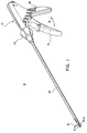
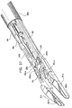
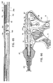
- FIG. 1 a preferred embodiment of the surgical clip applier of the subject disclosure is illustrated in FIG. 1, and is designated generally by reference numeral 10.
- Clip applier 10 includes handle portion 12 having pivoting or movable handle 14 and stationary handle 16. Manipulation of these handles 14, 16 actuates a tool assembly, such as jaw assembly 18, through elongated body portion 20.
- the junction at which body portion 20 is joined to handle portion 12 includes fluted rotation collar 22 for remotely varying the angular orientation of jaw assembly 18 relative to the surgical site.
- Jaw assembly 18 includes first and second juxtaposed jaw portions 24a and 24b, which are simultaneously movable between a substantially approximated configuration in which jaw portions 24a and 24b are in relatively close relation to one another and a spaced configuration in which jaw portions 24a and 24b are separatable at least a sufficient distance to receive an unformed surgical clip therebetween.
- movable handle 14 is shown in a fully open or "at-rest” position with respect to handle 16. Pivoting movement of movable handle 14 with respect to stationary handle 16 in the direction of arrow "A" from the open position to the closed position defines a closing stroke. During this closing stroke, jaw portions 24a and 24b are maintained in the spaced configuration as the distalmost surgical clip is advanced between the spaced apart jaw portions. Further pivoting of movable handle 14 approximates jaw portions 24a and 24b to deform the surgical clip.
- surgical clip applier 10 will now be described with respect to various subassemblies.
- surgical clip applier 10 includes subassemblies for the handle portion 12, jaw assembly 18, spindle subassembly 72, and a clip advancement structure 178.
- each of these subassemblies can be individually completed at separate workstations. Subsequently, the finished subassemblies may be put together in a final assembly procedure as will be described in greater detail below.
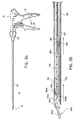
- FIG. 2 illustrates the components of handle portion 12 of instrument 10.
- Handle portion 12 includes left and right housing portions 26a and 26b respectively, in which the components of the handle portion are positioned. Housing portions 26a and 26b are positioned by screws 28a, 28b, 28c and 28d inserted within apertures 30a, 30b, 30c and 30d. Housing portions 26a and 26b are alternatively secured together by sonic welding or other known means.
- Movable handle 14 is mounted to housing portions 26a and 26b by pin 32 which permits pivotal motion of handle 14 with respect to stationary handle 16.
- Movable handle 14 further includes clevis 34 connected to a driver member, such as pusher plate 36, by contacting pin connector 38.
- Pusher plate 36 is mounted within recess 40 defined in housing portions 26a and 26b for reciprocal longitudinal motion therein.
- Clevis 34 includes a pair of spaced apart shackles 42a and 42b, each of which has an elongated aperture 44a and 44b defined therethrough for reception of pin connector 38, which is slidable therein. Apertures 44a and 44b provide a "lost-motion" feature which effectively disengages clevis 34 from pin connector 38 and drive bar 36. In particular, initial movement of movable handle 14 away from stationary handle 16 causes no movement of drive bar 36.
- Pusher plate 36 is operatively connected to the jaw assembly as will be described below.
- Pusher plate 36 may be stamped or machined from a single piece of sheet metal or rigid engineering plastic.
- Pusher plate 36 includes an aperture 46 for the reception of pin connector 38.
- Return spring 48 configured to engage shoulder portion 50 of pusher plate 36, is provided to normally bias pusher plate 36 proximally and thereby to normally bias movable handle 14 to the open position.
- Ratchet assembly 52 includes rack 54 having a plurality of ratchet teeth 56 formed on a proximal portion of pusher plate 36 and pawl 58 disposed in handle portion 12. Distal portion 60 and proximal portion 62 of rack 54 are devoid of ratchet teeth 56. Pawl 58 is rotatably mounted by pawl pin 64 and normally biased into engagement with the ratchet teeth of rack 54 by spring 66. As illustrated in FIG. 3, each of the ratchet teeth 56 on rack 54 has a substantially vertical portion and a substantially sloping portion to permit incremental distal advancement of pusher plate 36 while restricting proximal movement of pusher plate 36. Pawl 58 is provided with center tooth 68 and smaller side teeth 70a and 70b to provide positive engagement with ratchet teeth 56.
- flag 72 is constructed of a flexible material, such as plastic, and has a mounting portion 74 at a first end adjacent clevis 34 and is movable therewith.
- pin connector 38 passes through aperture 76 in mounting portion 74.
- the second, free end of flag 72 is slidably mounted in channel 76 adjacent the proximal end portion of housing 26a and 26b.
- Window 78 is defined in housings 26a and 26b to permit viewing of a portion of flag 72 therethrough.
- a marked portion 73 (not shown) of flag 72 appears in window 78 when the supply of surgical clips in surgical clip applier 10 has been depleted.
- Pusher plate 36 includes bifurcated distal portion 80 having prongs 82a and 82b which facilitate rotatable mounting to an actuator, such as spindle 72.
- actuator such as spindle 72
- pusher plate 36 and spindle 72 may be connected by any other known mounting structure including, e.g. a ball-and-socket arrangement.
- Rotation collar 22 provides angular rotation to spindle 72 and body 20.
- Rotation collar 22 is connected to bushing 84 by clip 86 and is angularly rotatable therewith.
- the proximal portion of bushing 84 is provided with a pair of circumferential flanges 88a and 88b, which are rotatably mounted in stepped bore 90 and secured therein by lip portion 92.
- Heavy gauge spring 94 and washer 96 surround bushing 84. Excessive closing force on clip applier 10 overcomes the resistance of spring 94 such that body portion 20 is distally advanced relative to handle assembly 12. This relative movement temporarily disables clip applier 10 to prevent damage. Washer 86 prevents rotation of return spring 48 during angular rotation of rotation knob 22.
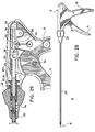
- jaw assembly 18 includes elongated shank portions 100a and 100b connected at crown portion 102.
- Midline 104 is defined through each of shank portions 100a and 100b.
- the portion of jaw assembly 18 proximal to midline 104 constitutes the proximal portion of jaw assembly 18.
- the portion of jaw assembly 18 distal to midline 104 constitutes the distal portion of jaw assembly 18.
- Resilience in shank portions 100a and 100b permits relative approximation and spacing of juxtaposed jaw portions 24a and 24b.
- a pair of elongated channels 106a and 106b is provided on the inner surfaces of jaw portions 24a and 24b for reception of a surgical clip as will be described below.
- Jaw assembly 18 further includes proximal legs 108a and 108b, having a plurality of radially outwardly extending tabs 110a, 110b, 110c, and 110d formed thereon. These tabs are used for mounting and assembly as will be described in greater detail below. Longitudinal channels 112a and 122b are defined between legs 108a, 108b and crown 102 to receive corresponding guide ridges at a distal portion of spindle subassembly 72, as will be described below.
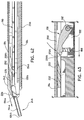
- FIG. 4A illustrates, in enlarged form, a pair of position tabs 114a and 114b disposed on elongated shank portions 100a and 100b respectively, to cam jaw portions 24a and 24b as will be described below.
- jaws 24a and 24b are configured to receive surgical fasteners into channels 106a (illustrated in phantom lines) and 106b.
- Reception surface or target area 116 is defined at a proximal face of each of jaws 24a and 24b at the junction with shanks 100a and 100b.
- target area 116 is determined by vertical height 118 and lateral width 120. Each of these dimensions is maximized to the extent possible in order to provide a large area to receive the surgical fasteners and transfer them to channels 106a and 106b.
- Angle 122 is defined by target area 116 with the longitudinal axis to direct fasteners laterally inward.
- Back-cut angle 124 is defined vertically by the plane of target area 116 and the longitudinal axis. Back-cut angle 124 of less than 90 degrees is provided and radiused portion 126 is minimized in size in order to direct fasteners downward and to prevent such fasteners from inadvertently riding over the top of jaws 24a and 24b.
- each of jaw portions 24a and 24b includes raised camming surfaces 128a and 128b formed on the bottom surface thereof.
- Camming surfaces 128a and 128b increase in width from the proximal end to the distal end of jaws 24a and 24b.
- camming surfaces 128a and 128b are disposed at a distal portion of jaw portions 24a and 24b adjacent inner surfaces 130a and 130b of jaw portions 24a and 24b.
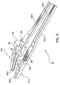
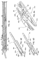
- spindle subassembly 72 extends along a substantial length of body portion 20.
- Spindle subassembly 72 includes spindle 132, which is advanceable by handle assembly 12, and driver 134 which has a semicircular cross-section and includes dual camming structure for opening and closing jaw portions 24a and 24b.
- Driver 134 is always positioned adjacent jaws 24a and 24b to provide stability for the jaws against twisting.
- Linkage bar 136 and detent spring 138 are provided to interlock spindle 132 and driver 134 during a portion of the longitudinal travel of spindle 132.
- a distal end portion of linkage bar 136 is received in a T-slot in driver 134, and linkage bar 136 is longitudinally movable with driver 134.
- Detent spring 138 is pivotable within slot 139 in linkage bar 136.
- Linkage bar 136 includes boss 140 formed on a lower surface thereof, which is slidable in elongated slot 142 at a distal end portion of spindle 132.
- detent spring 138 is normally biased upwardly and out of slot 142. This arrangement permits spindle 132 to slide while driver 134 remains stationary adjacent jaws 24a and 24b.
- detent spring 138 is moved downward into elongated slot 142 to provide a positive interlock between spindle 132 and driver 134.
- driver 134 is driven by spindle 132 in order to cam jaws 24a and 24b closed.
- Guide ridges 143a and 143b adjacent slot 142 on spindle 72 stabilize jaw assembly 18 with respect to outer sleeve 256 (not shown), as will be described below.
- driver 132 is disengaged from spindle 132, such that driver 134 remains adjacent jaws 24a and 24b, while spindle 132 returns proximally.
- Channel structure 144 on driver 134 is configured with a groove pattern to control and cam jaw portions 24a and 24b to a spaced-apart position.
- Jaw closure structure 146 includes a bifurcated cam configuration to approximate jaw portions 24a and 24b about a surgical clip.
- a medial portion of spindle 132 includes trip lever assembly 156.
- Trip lever assembly 156 includes trip lever 158 mounted on spindle 132 and disposed within longitudinally aligned recess 160.
- Trip lever 158 is pivotably retained therein by pivot pin 162.
- Distal tab 164 of trip lever 156 is normally biased upward by trip lever spring 166.
- Trip lever 158 defines mounting aperture 168 to snap fit over pivot pin 162.
- Distal tab 164 includes a pair of laterally projecting pins 170a and 170b configured to engage a camming surface on clip advancement subassembly 178, as will be described below. It is contemplated that the trip lever and spring arrangement could be substituted with other equivalent structure including, e.g., a leaf spring or other resilient member.
- Longitudinal recess 160 receives wedge member 172, which is longitudinally slidable therein.
- Wedge member 172 is connected to thrust bar 184, described below, and has an angle lower surface 174 corresponding to an angled upper surface 161 (not shown) of recess 160. Theses surfaces are configured to interact when the supply of fasteners in surgical instrument 10 has been depleted.
- a hemispherical portion 176 of spindle 132 having a flat upper surface is provided distal to the trip lever assembly 156. Both hemispherical portion 176 and trip lever assembly 156 are configured to engage with clip advancement subassembly 178 as will be described below. Sealing member, such as O-ring seal 175, is positioned about an annular groove in spindle 132 to prevent escape of fluids or insufflation gases during the surgical procedure.
- channel structure 144 includes raised center block 148.
- a pair of longitudinally elongated parallel channels 150a and 150b extend along the sides of center block 148.
- Proximal zone or recess 152 is disposed proximal to center block 148.
- Channel structure 148 is configured to slidably receive position tabs 114a and 114b of jaw assembly 18 (See, FIG. 6).
- Jaw closure structure 146 includes a bifurcated configuration having a pair of camming surfaces 154a and 154b in a tapering V-shaped configuration to cooperate with raised camming surfaces 128a and 128b on jaw assembly 18.
- camming surfaces 154a and 154b of driver 134 are disposed in surrounding "T-slot" arrangement with respect to raised camming surfaces 128a and 128b of jaws 24a and 24b to provide stability to the jaws during overall operation of the instrument. Distal advancement of driver 134 during interlocking engagement with spindle 132 moves jaw portions 24a and 24b into approximation.
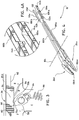
- clip advancement subassembly 178 is depicted including upper housing 180, lower housing 182, and thrust bar or clip pusher 184.
- upper housing 180 has a substantially semicircular or trapezoidal cross-section and includes recess 188.
- Upper housing 180 is connected to lower housing 182.
- Substantially rectangular feed chute 186 is defined by upper housing 180 and by side walls 181a and 181b and base portion 183 of lower housing 182.
- feed chute 186 stores a stack 190 of U-shaped surgical clips 192 therein, including a distalmost surgical clip 192a.
- Surgical clip stack 190 is configured such that legs 194c of surgical clip 192c are substantially in contact with the crown portion 196b of the next distal surgical clip 192b.
- the stack 190 of surgical clips 192 is urged towards the distal portion of feed chute 186 by clip follower 198 which is biased distally by follower spring 200 positioned in recess 188 of upper housing 180.
- follower spring 200 positioned in recess 188 of upper housing 180.
- the proximal end of spring 200 is retained by retainer block 202.
- a pair of clip stops 208a and 208b inhibit a distalmost surgical clip 192a from moving into the jaw assembly 18 by contacting the crown portion 196a of surgical clip 192a.
- Boss 204 on retainer block 202 is received in mounting aperture 206 at a proximal portion of lower housing 182 (FIG. 14).
- thrust bar 184 is slidable along upper surface 210 of upper housing 180.
- thrust bar 184 is distally advanced by spindle 132 (not shown), as will be described below.
- Thrust bar 184 is biased proximally by return spring 212.
- a distal end of return spring 212 abuts retainer block 202.
- the proximal end of return spring 212 surrounds supporting pin 214 which is retained by flange 216 on thrust bar 184.
- the proximal end portion of retaining block 202 has a trip lever engaging configuration 218 formed thereon.
- a pair of outer sloping surfaces 220a and 220b are formed on either side of recessed, center sloping surface 222. Outer sloping surfaces 220a and 220b are configured to interact with pins 170a and 170b of trip lever 158 as will be described below.
- the distal end portion of thrust bar 184 includes an angularly depending portion 224 which includes a rib 225 to strengthen thrust bar 184 during advancement of surgical clips 192.
- a bifurcated clip engaging portion 226 has a leading edge 228 and a sloping trailing edge 230.
- upper housing 180 defines a plurality of recesses 232 including raised tabs 234 which receive flanges 236a, 236b including ears 237 of lower housing 182 to mount lower housing 182 and upper housing 180.
- Recess 188 communicates with feed chute 186, and provides access for follower spring 200 and clip follower 198 inserted therein.
- Lock lever 231 is formed in base portion 183 as an integrally formed cantilevered member connected to base 183 at its proximal end and extending upwardly at its distal end.
- FIG. 17 the various components of clip advancement subassembly 172 are illustrated in assembled combination.
- upper housing 180 and lower housing 182 are assembled.
- Thrust bar 184 is slidably mounted on upper housing 180.
- FIG. 18 illustrates in enlarged form the position of distalmost surgical clip 192a at the distal end of feed chute 186.
- Legs 194a of surgical clip 192a are stabilized by side walls 181a and 181b, and crown 196a is supported by clip stops 208a and 208b.
- Angularly depending portion 224 of thrust bar 184 extends into feed chute 186.
- Leading edge 228 of clip engaging portion 226 is configured to contact crown 196a of surgical clip 192a to advance the clip beyond clip stops 208a and 208b as will be described below.
- nosepiece 240 defines a longitudinal slot 242 to direct angularly depending portion 224 of thrust bar 184.
- a pair of camming surfaces 244a and 244b are defined on the bottom portion of nosepiece 240 to apply a downward force on jaw portions 24a and 24b to provide positive engagement of the jaw portions with camming structures 144 and 146 on driver 134.
- endoscopic portion 20 is assembled from the previously described components.
- Jaw assembly 18 is positioned adjacent driver 134 of spindle subassembly 72 such that jaw closing structure 146 is in surrounding engagement with raised camming surfaces 128a and 128b of jaws 24a and 24b.
- position tabs 114a and 114b on jaws 24a and 24b are disposed within channel structure 144 on driver 134.
- nosepiece 240 is positioned adjacent lower housing 182 such that angularly depending portion 224 of thrust bar 184 is slidable within slot 242.
- Lower housing 182 is configured to rest partially on hemispherical portion 176 of spindle 72 and partially on jaw assembly 18.
- Longitudinal slot 250 and aperture 252 are defined at a proximal portion of thrust bar 184.
- Longitudinal slot 250 is positioned in interlocking arrangement with trip lever assembly 156.
- Boss 254 on an upper surface of wedge member 172 is received in aperture 252 in thrust bar 184 such that wedge member 172 and thrust bar 184 are longitudinally movable as a unit.
- a substantially cylindrical profile is defined by the combination of spindle subassembly 72 and clip advancement subassembly 178.
- Outer sleeve 256 is provided defining a cylindrical internal passage 258 therethrough having a circular cross-section. Internal passage 258 is sized to receive the assembled components described above, which are inserted into the distal end portion 260 of outer sleeve 256.
- Apertures 262a, 262b, 262c, and 262d at distal portion 260 of outer sleeve 256 are configured to receive tabs 110a, 110b, 110c, and 110d of jaw assembly 18 in snap-fitting arrangement.
- Bushing 84 is slidably received in rotating collar 22.
- Bushing 84 includes a substantially cylindrical portion 270 defining a flat surface 272, and a lateral groove 274 (FIG. 25).
- Spring 94 and washer 96 are positioned about proximal portion of sleeve 256, such that flat portion 259 of flange 257 cooperates with a corresponding flat tab 97 on washer 96.
- Spring 94, washer 96 and body 20 are inserted in bore 23 of rotation collar 22.
- Cylindrical portion 270 of bushing 84 is inserted into bore 23 of rotation collar 22.
- U-shaped clip 86 is passed through opening 276 in rotation collar 22, such that legs 278a and 278b of clip 86 are received in grooves 274 of bushing 84, as shown in FIG. 27.
- Return spring 48 and washer 98 are positioned within bore 275 over pusher plate 36 (FIG. 26).
- Bifurcated distal portion 80 of pusher plate 36 is connected to a proximal mounting portion 278 of spindle 72.
- annular notch 280 is configured to be received by prongs 80a and 80b for angular rotation of spindle 72 with respect to pusher plate 36.
- Peripheral fins 88a and 88b of bushing 84 are retained in housing by circumferential flange 92.
- clip applier 10 is initially disposed with movable handle 14 in the open or "at-rest" position.
- Pusher plate 36 is positioned in a proximal position with respect to housing portions 26a and 26b.
- driver 134 is disposed adjacent jaws 24a and 24b.
- Position tabs 114a and 114b of jaw assembly 18 are disposed in channel structure 144, and more particularly in parallel channels 150a and 150b. Consequently, jaw portions 24a and 24b are maintained in a spaced-apart position.
- camming surfaces 154a and 154b are in engagement with raised camming surfaces 128a and 128b of jaws 24a and 24b. Movable handle 14 is maintained in the "at-rest” position during insertion of body portion 20 and jaw assembly 18 through the cannula.
- a single closing stroke of movable handle 14 towards stationary handle 16 is sufficient to first deploy and/or ensure that the jaw portions 24a and 24b are in a spaced apart position adjacent or around the tissue or structure to be crimped, to sequentially advance a clip to the spaced-apart jaw portions, to reposition the clip-containing jaw portions, as desired, and to finally deform the clip on the desired structure.
- Closure from the "at-rest" position of movable handle 14 to an intermediate position constitutes an initial throw thereof. Finally, closure from the intermediate position to the closed position constitutes a final throw.
- FIGS. 32-39 The beginning of the initial throw is shown in FIGS. 32-39.
- clevis 34 engages pin connector 38 such that pusher plate 36 and spindle 132 advance distally against the bias of spring 48.
- Pawl 58 is in engagement with rack 54 to index incremental advancement of pusher plate 36 and prevent pusher plate 36 from returning proximally.
- FIG. 36 depicts clip follower 198 in biased relationship with the stack 190 of surgical clips 192.
- clip engaging portion 226 engages the crown 196a of the distalmost surgical clip 192a against the restraining force of clip stops 208a and 208b. Further advancement of thrust bar 184 advances surgical clip 192a beyond clip stops 208a and 208b as shown in FIG. 39.
- Clip camming surface 282 contacts crown 196a and directs legs 194a of surgical clip 192a into channels 106a and 106b on the inner surfaces of jaw portions 24a and 24b. The spacing of jaw portions 24a and 24b is selected such that a tight frictional grip is created between jaw portions 24a and 24b and surgical clip 192a to prevent surgical clip 192a from falling out of the jaw portions.
- movable handle 14 continues to operably advance pusher plate 36 distally.
- Pawl 58 is engaged with the ratchet teeth 56 on rack 54 to index advancement of spindle 132 and to prevent proximal movement thereof during clip advancement.
- clip engaging portion 226 has advanced surgical clip 192a into channels 106a (not shown) and 106b in the jaw portions.
- spindle 132 advances trip lever 158 such that laterally projecting pins 170a and 170b contact sloping surfaces 220a and 220b on mounting block 202.
- trip lever 158 pivots about pin 162 in the direction of arrow "C” against the bias of spring 166, and distal tab 164 moves downward and out of slot 250 in thrust bar 184.
- Thrust bar 184 returns proximally in the direction of arrow "P” due to the bias of return spring 212.
- Spindle 132 continues to move distally as shown in FIG. 45.
- the resilience of angled portion 224 and the shallow slope of trailing edge 230 enable clip engaging portion 226 to ride over crown 196b of the next surgical clip 192b, as shown in FIG. 46.
- handle 14 is moved through the final throw towards the closed position.
- Pawl 58 is disposed in the proximal zone 62 of rack 54 that is devoid of teeth 56.
- crown portion 102 of jaw assembly 18 contacts detent spring 138, which is pivoted downward into slot 142 at the distal end portion of spindle 132.
- linkage bar 136 and driver 134 is
- jaws 24a and 24b are cammed into approximation by driver 134.
- position tabs 114a and 114b pass from the parallel channels 150a and 150b to the proximal zone 152, in which jaw portions 24a and 24b are freely movable.
- Camming surfaces 154a and 154b on jaw closure structure 146 of driver 134 begin to engage raised camming surfaces 128a and 128b on jaw portions 24a and 24b.
- Guide ridges 143a and 143b at distal end portion of spindle 132 are advanced into channels 112a and 112b between crown 102 and proximal legs 108a and 108b of jaw assembly 18.
- Guide ridges 143a and 143b exert lateral force on proximal legs 108a and 108b, thereby maintaining tabs 110a, 110b, 110c, 110d in apertures 262a, 262b, 262c, 262d and thereby preventing jaw assembly 18 from being ejected distally from sleeve 256.
- jaw portions 24a and 24b are gradually brought into approximation with distal movement of driver 134.
- raised camming surfaces 128a and 128b are wider at the distal portion than at the proximal portion. Therefore, progressive movement of V-shaped jaw closure structure 146 cams jaw portions 24a and 24b closed.
- the proximity of jaw closure structure 146 and camming surfaces 154a and 154b to the distal portion of jaw portions 24a and 24b enables sufficient force to be exerted on jaw portions 24a and 24b to deform clip 192 (not shown) and compress blood vessels or other body tissue surrounded thereby.
- FIGS. 54-58 the sequence of movements during the return stroke of handle 14 will be described.
- handle 14 moves to the open position due to the normal bias of return spring 48 (not shown).
- Spindle 132 and driver 134 are moved proximally due to the interlocking of detent spring 138 in slot 142 of spindle 132 (FIG. 55).
- position tabs 114a and 114b are moved from proximal zone 152 into parallel slots 150a and 150b, as shown in FIG. 56. Further proximal movement of driver 134 is restrained by engagement of position tabs 114a and 114b with the distal portions of parallel slots 150a and 150b.
- detent spring 138 is positioned proximal to crown portion 102 as shown in FIG. 57.
- the normal upward bias of detent spring 138 moves spring 138 out of engagement with slot 142.
- spindle 132 is permitted to move proximally, while driver 134 remains stationary adjacent jaws 24a and 24b.
- FIGS. 59-55 a disabling feature of clip applier 10 will now be described.
- application of excessive force to clip applier 10 in closing handle 14 may occur, e.g., if jaws 24a and 24b (not shown) are applied to resistant tissue.
- driver 134 applies force to jaw assembly 18 to cam jaws 24a and 24b closed.
- the application of excessive force to driver 134 may eject jaw assembly 18 from sleeve 256 or otherwise damage jaw assembly 18.
- Sleeve 256 is normally biased in a proximal position by spring 94. More particularly, a proximal end of spring 94 biases washer 96 against flange 257 of sleeve 256.
- Spring 94 is rated to compress under a high degree of force. During normal operation of clip applier 10, the force exerted on spring 94 is insufficient to compress spring 94. Consequently, sleeve 256 is maintained in a stationary position as spindle 132 is advanced distally. When the force applied to instrument 10 exceeds the rating of spring 94, spring 94 begins to compress, as shown in FIG. 60. As spring 94 compresses, washer 96 moves distally, thereby moving sleeve 256 distally therewith to disable the clip applier.
- Clip follower 198 is advanced distally as each surgical clip 192 is applied. After the stack 190 of surgical clip 192 has been depleted, clip follower 198 is positioned at the distal end portion of lower housing 182, as illustrated in FIG. 61.
- Clip follower 198 includes body portion 286 and legs 288a and 288b, as shown in FIG. 62. Angled nosepiece 290 is formed at the distal end of body 286. Legs 288a and 288b are joined to body portion 286 at shoulder portions 292a and 292b, which are engaged by clip stops 208a and 208b.
- Web 294a is positioned between body 286 and leg 288a. Similarly, web 294b is positioned between body 286 and leg 288b.
- FIG. 63 illustrates recess 296 defined on a bottom surface of clip follower 198. Recess 296 has a substantially vertical abutment face 298 (FIG. 64).
- Clip follower 198 is distally advanced in feed chute 186 until clip stops 208a and 208b engage shoulder portions 292a and 292b.
- Lock lever 231 is deflected downward in a flattened position until recess 296 of clip follower 198 is positioned over lock lever 231.
- Thrust bar 184 begins an initial proximal movement after trip lever 158 is pivoted out of engagement with thrust bar 184 (See, FIGS. 43-45).
- Thrust bar 184 is prevented from moving proximally due to the positioning of clip follower 198 at the distal end of feed chute 186.
- bifurcated distal portion 226 of thrust bar 184 contacts webs 294a (not shown) and 294b and angled nosepiece 290 of clip follower 198, thereby forcing thrust bar 184 upward against camming surfaces 244a and 244b of nosepiece 240 and forcing rib 225 against body 286 of clip follower 198.
- Clip follower 198 acts as a blocking mechanism to prevent movement of the thrust bar 184.
- thrust bar 184 is restrained from further proximal movement due to the insufficient clearance between nosepiece 240 and clip follower 198.
- FIG. 65 illustrates, when thrust bar 184 is blocked in a distal position, wedge member 172 is likewise prevented from moving proximally within slot.
- angled surface 161 of slot 160 is brought into approximation with angled surface 174 of stationary wedge member 172.
- Interaction of angled surfaces 174 and 161 causes wedge member 172 and spindle 132 to be moved radially outward against the inner surface of sleeve 256 as indicated by the arrows.
- Such movement of wedge member 172 and spindle 132 binds these components from further movement and effectively disables instrument 10.
- apertures 44a and 44b in clevis 34 are configured such that no motion is transferred from handle 14 to pin 38 during partial opening of handle 14. This configuration prevents handle 14 from being opened to forcibly overcome interaction of wedge member 172 and spindle 132.
- marked portion 73 on flag 72 is displayed in window 78 to provide a visual indication that the clip supply has been depleted (FIG. 68).
- jaw assembly and endoscopic portions may be sized to be accommodated in cannula assemblies of various sizes.
- the claims which follow identify embodiments of the invnetion additional to those described in detail above.
Abstract
Description
Claims (15)
- An apparatus for application of surgical clips to body tissue, which comprises:a) a handle portion;b) a body extending distally from the handle portion and defining a longitudinal axis;c) a plurality of surgical clips disposed within the body;d) a jaw assembly mounted adjacent a distal end portion of the body, the jaw assembly including first and second jaw portions movable between a spaced-apart and an approximated position;e) a clip pusher configured to individually distally advance a surgical clip to the jaw assembly while the jaw portions are in the spaced-apart position;f) an actuator at least partially disposed within the body and longitudinally movable in response to actuation of the handle portion;g) a jaw closure member positioned adjacent the first and second jaw portions to move the jaw portions to the approximated position, the actuator and the jaw closure member defining an interlock therebetween to produce simultaneous movement of the actuator and the jaw closure member during a portion of the longitudinal movement of the actuator.
- An apparatus for application of surgical clips to body tissue, which comprises:a) a handle portion;b) a body extending distally from the handle portion and defining a longitudinal axis;c) a plurality of surgical clips disposed within the body;d) a jaw assembly mounted adjacent a distal end portion of the body, the jaw assembly including first and second jaw portions movable between a spaced-apart and an approximated position;e) a clip pusher movably mounted to individually distally advance a surgical clip to the jaw assembly while the jaw portions are in the spaced-apart position;f) an actuator at least partially disposed within the body and longitudinally movable in response to actuation of the handle portion;g) a jaw closure member positioned adjacent the first and second jaw portions, the actuator and the jaw closure member defining a selectively engageable interlock therebetween to produce simultaneous movement of the actuator and the jaw closure member when the actuator is positioned adjacent the distal end portion of the body.
- An apparatus for application of surgical clips to body tissue, which comprises:a) a handle portion having a first handle and a second handle mounted for relative movement, the handles defining a single closing stroke between an open position and a closed position, the closing stroke defining an initial throw and a final throw;b) a body extending distally from the handle portion and defining a longitudinal axis;c) a plurality of surgical clips disposed within the body;d) a jaw assembly mounted adjacent a distal end portion of the body, the jaw assembly including first and second jaw portions movable between a spaced-apart and an approximated position;e) a clip pusher configured to individually distally advance a surgical clip to the first and second jaw portions while the jaw portions are in the spaced-apart position during the initial throw of the handles;f) an actuator at least partially disposed within the body and longitudinally movable in response to actuation of the handle portion;g) a jaw closure member positioned adjacent the first and second jaw portions, the actuator and the jaw closure member defining an interlock therebetween to produce simultaneous movement of the actuator and the jaw closure member during the final throw of the handles.
- An apparatus as recited in any one of the preceding claims, wherein the jaw closure member includes a portion engaged with the first and second jaw portions to stabilize the jaw portions.
- An apparatus as recited in claim 4, wherein the jaw closure member includes camming structure which cooperates with camming surfaces on the first and second jaw portions.
- An apparatus as recited in any one of the preceding claims, wherein the first and second jaw portions each define a reception surface for receiving a surgical clip, the reception surface defining an angle with the longitudinal axis of less than 90 degrees.
- An apparatus as recited in any one of the preceding claims, wherein the clip pusher and the actuator define an interlock therebetween to produce simultaneous movement of the clip pusher and the actuator during a portion of the longitudinal movement of the actuator.
- An apparatus as recited in any one of the preceding claims, which further comprises a release to disengage the interlock between the clip pusher and the actuator.
- An apparatus as recited in any one of the preceding claims, which further includes a blocking mechanism to prevent movement of the clip pusher when the plurality of surgical clips has been applied.
- An apparatus as recited in claim 9, wherein the clip pusher and the actuator define a jamming mechanism to prevent movement of the clip pusher and the actuator when the plurality of surgical clips has been applied.
- An apparatus as recited in claim 10, the jamming mechanism including surfaces on the clip pusher and actuator configured to produce a frictional engagement between the clip pusher, the actuator and the body.
- An apparatus as recited in any one of the preceding claims, which further comprises a visual indicator on the handle portion that the plurality of surgical clips has been applied.
- An apparatus as recited in any one of the preceding claims, wherein a handle portion includes a ratchet mechanism to index progressive longitudinal movement of the actuator.
- An apparatus as recited in claim 13, wherein the ratchet mechanism includes a rack and a pawl having a plurality of teeth.
- An apparatus as recited in any one of the preceding claims, wherein the handles define an return stroke between a closed position and an open position, the handle portion including a disengagement mechanism to disengage the handle portion from the actuator during a portion of the return stroke.
Priority Applications (1)
| Application Number | Priority Date | Filing Date | Title |
|---|---|---|---|
| EP20030026579 EP1405601A1 (en) | 1996-10-03 | 1997-09-12 | Apparatus for applying surgical clips |
Applications Claiming Priority (2)
| Application Number | Priority Date | Filing Date | Title |
|---|---|---|---|
| US08/725,181 US5833696A (en) | 1996-10-03 | 1996-10-03 | Apparatus for applying surgical clips |
| US725181 | 1996-10-03 |
Related Child Applications (1)
| Application Number | Title | Priority Date | Filing Date |
|---|---|---|---|
| EP20030026579 Division EP1405601A1 (en) | 1996-10-03 | 1997-09-12 | Apparatus for applying surgical clips |
Publications (2)
| Publication Number | Publication Date |
|---|---|
| EP0834286A1 true EP0834286A1 (en) | 1998-04-08 |
| EP0834286B1 EP0834286B1 (en) | 2003-11-19 |
Family
ID=24913485
Family Applications (2)
| Application Number | Title | Priority Date | Filing Date |
|---|---|---|---|
| EP97115934A Expired - Lifetime EP0834286B1 (en) | 1996-10-03 | 1997-09-12 | Apparatus for applying surgical clips |
| EP20030026579 Withdrawn EP1405601A1 (en) | 1996-10-03 | 1997-09-12 | Apparatus for applying surgical clips |
Family Applications After (1)
| Application Number | Title | Priority Date | Filing Date |
|---|---|---|---|
| EP20030026579 Withdrawn EP1405601A1 (en) | 1996-10-03 | 1997-09-12 | Apparatus for applying surgical clips |
Country Status (7)
| Country | Link |
|---|---|
| US (1) | US5833696A (en) |
| EP (2) | EP0834286B1 (en) |
| JP (2) | JP4002640B2 (en) |
| AU (1) | AU743794B2 (en) |
| CA (1) | CA2213896C (en) |
| DE (1) | DE69726238T2 (en) |
| ES (1) | ES2206638T3 (en) |
Cited By (55)
| Publication number | Priority date | Publication date | Assignee | Title |
|---|---|---|---|---|
| EP0966925A1 (en) * | 1998-06-26 | 1999-12-29 | Ethicon Endo-Surgery, Inc. | Applier for implantable surgical marker |
| WO2001067965A1 (en) * | 2000-03-17 | 2001-09-20 | Femcare (Cyprus) Limited | Applicator for surgical clips |
| EP1146823A1 (en) * | 1999-01-25 | 2001-10-24 | Applied Medical Resources Corporation | Modular ligating apparatus and method |
| WO2005110248A2 (en) * | 2004-04-16 | 2005-11-24 | Applied Medical Resources Corporation | Multi-fire surgical clip applier |
| EP1712189A3 (en) * | 2005-04-14 | 2007-01-24 | Ethicon Endo-Surgery, Inc. | Surgical clip applier ratchet mechanism |
| US7297149B2 (en) * | 2005-04-14 | 2007-11-20 | Ethicon Endo-Surgery, Inc. | Surgical clip applier methods |
| EP1908423A3 (en) * | 2006-10-02 | 2008-12-24 | Tyco Healthcare Group, LP | Endosopic surgical clip applier |
| US7731725B2 (en) | 1999-01-25 | 2010-06-08 | Applied Medical Resources Corporation | Surgical instrument with improved handle assembly |
| US7740641B2 (en) | 2005-04-14 | 2010-06-22 | Ethicon Endo-Surgery, Inc. | Clip applier with migrational resistance features |
| US8038686B2 (en) | 2005-04-14 | 2011-10-18 | Ethicon Endo-Surgery, Inc. | Clip applier configured to prevent clip fallout |
| US8236012B2 (en) | 2005-04-14 | 2012-08-07 | Ethicon Endo-Surgery, Inc. | Surgical clip advancement mechanism |
| US8262679B2 (en) | 2009-10-09 | 2012-09-11 | Ethicon Endo-Surgery, Inc. | Clip advancer |
| US8267945B2 (en) | 2009-10-09 | 2012-09-18 | Ethicon Endo-Surgery, Inc. | Clip advancer with lockout mechanism |
| US8336556B2 (en) | 2008-08-25 | 2012-12-25 | Covidien Lp | Surgical clip applier and method of assembly |
| EP2540232A1 (en) * | 2008-08-29 | 2013-01-02 | Covidien LP | Endoscopic surgical clip applier |
| US8403945B2 (en) | 2010-02-25 | 2013-03-26 | Covidien Lp | Articulating endoscopic surgical clip applier |
| US8403946B2 (en) | 2010-07-28 | 2013-03-26 | Covidien Lp | Articulating clip applier cartridge |
| US8486091B2 (en) | 2008-08-29 | 2013-07-16 | Covidien Lp | Endoscopic surgical clip applier |
| US8545486B2 (en) | 2009-12-15 | 2013-10-01 | Covidien Lp | Surgical clip applier |
| US8734469B2 (en) | 2009-10-13 | 2014-05-27 | Covidien Lp | Suture clip applier |
| US8915930B2 (en) | 2005-04-14 | 2014-12-23 | Ethicon Endo-Surgery, Inc. | Force limiting mechanism for medical instrument |
| US8968337B2 (en) | 2010-07-28 | 2015-03-03 | Covidien Lp | Articulating clip applier |
| US9011464B2 (en) | 2010-11-02 | 2015-04-21 | Covidien Lp | Self-centering clip and jaw |
| US9011465B2 (en) | 2004-10-08 | 2015-04-21 | Covidien Lp | Endoscopic surgical clip applier |
| US9113893B2 (en) | 2008-08-29 | 2015-08-25 | Covidien Lp | Endoscopic surgical clip applier with clip retention |
| US9113892B2 (en) | 2013-01-08 | 2015-08-25 | Covidien Lp | Surgical clip applier |
| WO2015165601A1 (en) * | 2014-04-28 | 2015-11-05 | Aesculap Ag | Medical shaft-type instrument with an immersion recess in the tip of the tongue |
| US9186136B2 (en) | 2009-12-09 | 2015-11-17 | Covidien Lp | Surgical clip applier |
| US9186153B2 (en) | 2011-01-31 | 2015-11-17 | Covidien Lp | Locking cam driver and jaw assembly for clip applier |
| US9364216B2 (en) | 2011-12-29 | 2016-06-14 | Covidien Lp | Surgical clip applier with integrated clip counter |
| US9364239B2 (en) | 2011-12-19 | 2016-06-14 | Covidien Lp | Jaw closure mechanism for a surgical clip applier |
| US9398917B2 (en) | 2007-03-26 | 2016-07-26 | Covidien Lp | Endoscopic surgical clip applier |
| US9408610B2 (en) | 2012-05-04 | 2016-08-09 | Covidien Lp | Surgical clip applier with dissector |
| US9414844B2 (en) | 2008-08-25 | 2016-08-16 | Covidien Lp | Surgical clip appliers |
| US9480477B2 (en) | 2006-10-17 | 2016-11-01 | Covidien Lp | Apparatus for applying surgical clips |
| US9498227B2 (en) | 2007-04-11 | 2016-11-22 | Covidien Lp | Surgical clip applier |
| US9532787B2 (en) | 2012-05-31 | 2017-01-03 | Covidien Lp | Endoscopic clip applier |
| US9549741B2 (en) | 2008-08-25 | 2017-01-24 | Covidien Lp | Surgical clip applier and method of assembly |
| US9687247B2 (en) | 2004-10-08 | 2017-06-27 | Covidien Lp | Apparatus for applying surgical clips |
| US9750500B2 (en) | 2013-01-18 | 2017-09-05 | Covidien Lp | Surgical clip applier |
| US9763668B2 (en) | 2004-10-08 | 2017-09-19 | Covidien Lp | Endoscopic surgical clip applier |
| US9775624B2 (en) | 2013-08-27 | 2017-10-03 | Covidien Lp | Surgical clip applier |
| US9775623B2 (en) | 2011-04-29 | 2017-10-03 | Covidien Lp | Surgical clip applier including clip relief feature |
| US9931124B2 (en) | 2015-01-07 | 2018-04-03 | Covidien Lp | Reposable clip applier |
| US9968362B2 (en) | 2013-01-08 | 2018-05-15 | Covidien Lp | Surgical clip applier |
| US10159491B2 (en) | 2015-03-10 | 2018-12-25 | Covidien Lp | Endoscopic reposable surgical clip applier |
| EP3441021A1 (en) * | 2017-08-10 | 2019-02-13 | Ethicon LLC | Surgical clip applier jaw alignment |
| US10292712B2 (en) | 2015-01-28 | 2019-05-21 | Covidien Lp | Surgical clip applier with integrated cutter |
| US10390831B2 (en) | 2015-11-10 | 2019-08-27 | Covidien Lp | Endoscopic reposable surgical clip applier |
| US10702278B2 (en) | 2014-12-02 | 2020-07-07 | Covidien Lp | Laparoscopic surgical ligation clip applier |
| US10786273B2 (en) | 2018-07-13 | 2020-09-29 | Covidien Lp | Rotation knob assemblies for handle assemblies |
| US10863992B2 (en) | 2017-08-08 | 2020-12-15 | Covidien Lp | Endoscopic surgical clip applier |
| US11033256B2 (en) | 2018-08-13 | 2021-06-15 | Covidien Lp | Linkage assembly for reusable surgical handle assemblies |
| US11253267B2 (en) | 2018-08-13 | 2022-02-22 | Covidien Lp | Friction reduction mechanisms for handle assemblies |
| US11259887B2 (en) | 2018-08-10 | 2022-03-01 | Covidien Lp | Feedback mechanisms for handle assemblies |
Families Citing this family (713)
| Publication number | Priority date | Publication date | Assignee | Title |
|---|---|---|---|---|
| CA2152407A1 (en) * | 1994-09-30 | 1996-03-31 | Duane Girard Uitenbroek | Laminate material and absorbent garment comprising same |
| US6086600A (en) | 1997-11-03 | 2000-07-11 | Symbiosis Corporation | Flexible endoscopic surgical instrument for invagination and fundoplication |
| US6551328B2 (en) * | 1997-11-03 | 2003-04-22 | Symbiosis Corporation | Surgical instrument for invagination and fundoplication |
| WO2001056455A2 (en) | 2000-02-04 | 2001-08-09 | Imagyn Medical Technologies California, Inc. | Surgical clip applier |
| JP4477280B2 (en) * | 2000-03-16 | 2010-06-09 | メディガス リミテッド | Gastric fistula wall forming device |
| IL139788A (en) * | 2000-11-20 | 2006-10-05 | Minelu Zonnenschein | Stapler for endoscopes |
| US6592596B1 (en) | 2000-05-10 | 2003-07-15 | Scimed Life Systems, Inc. | Devices and related methods for securing a tissue fold |
| US20020082621A1 (en) | 2000-09-22 | 2002-06-27 | Schurr Marc O. | Methods and devices for folding and securing tissue |
| US11229472B2 (en) | 2001-06-12 | 2022-01-25 | Cilag Gmbh International | Modular battery powered handheld surgical instrument with multiple magnetic position sensors |
| JP4632582B2 (en) * | 2001-07-02 | 2011-02-16 | 株式会社トップ | Surgical operation handle disassembly structure |
| JP4689099B2 (en) * | 2001-07-24 | 2011-05-25 | 株式会社トップ | Surgical clip applier |
| US7056330B2 (en) * | 2002-05-31 | 2006-06-06 | Ethicon Endo-Surgery, Inc. | Method for applying tissue fastener |
| ES2616695T3 (en) * | 2003-03-11 | 2017-06-14 | Covidien Lp | Staple application device with inclined jaw |
| US20070084897A1 (en) | 2003-05-20 | 2007-04-19 | Shelton Frederick E Iv | Articulating surgical stapling instrument incorporating a two-piece e-beam firing mechanism |
| US9060770B2 (en) | 2003-05-20 | 2015-06-23 | Ethicon Endo-Surgery, Inc. | Robotically-driven surgical instrument with E-beam driver |
| US8182501B2 (en) | 2004-02-27 | 2012-05-22 | Ethicon Endo-Surgery, Inc. | Ultrasonic surgical shears and method for sealing a blood vessel using same |
| US8215531B2 (en) | 2004-07-28 | 2012-07-10 | Ethicon Endo-Surgery, Inc. | Surgical stapling instrument having a medical substance dispenser |
| US11896225B2 (en) | 2004-07-28 | 2024-02-13 | Cilag Gmbh International | Staple cartridge comprising a pan |
| ES2650172T3 (en) | 2004-09-23 | 2018-01-17 | Covidien Lp | Bra applicator and ligation bra |
| US8409222B2 (en) | 2004-10-08 | 2013-04-02 | Covidien Lp | Endoscopic surgical clip applier |
| PL1802245T3 (en) | 2004-10-08 | 2017-01-31 | Ethicon Endosurgery Llc | Ultrasonic surgical instrument |
| AU2011203363B2 (en) * | 2004-10-08 | 2014-01-23 | Covidien Lp | Endoscopic surgical clip applier |
| US7731724B2 (en) | 2005-04-14 | 2010-06-08 | Ethicon Endo-Surgery, Inc. | Surgical clip advancement and alignment mechanism |
| US7699860B2 (en) * | 2005-04-14 | 2010-04-20 | Ethicon Endo-Surgery, Inc. | Surgical clip |
| US8523882B2 (en) | 2005-04-14 | 2013-09-03 | Ethicon Endo-Surgery, Inc. | Clip advancer mechanism with alignment features |
| US7419495B2 (en) * | 2005-08-25 | 2008-09-02 | Microline Pentax Inc. | Trigger lockout device for clip applying instrument |
| US20070049947A1 (en) * | 2005-08-25 | 2007-03-01 | Microline Pentax Inc. | Cinch control device |
| US7669746B2 (en) | 2005-08-31 | 2010-03-02 | Ethicon Endo-Surgery, Inc. | Staple cartridges for forming staples having differing formed staple heights |
| US11484312B2 (en) | 2005-08-31 | 2022-11-01 | Cilag Gmbh International | Staple cartridge comprising a staple driver arrangement |
| US7934630B2 (en) | 2005-08-31 | 2011-05-03 | Ethicon Endo-Surgery, Inc. | Staple cartridges for forming staples having differing formed staple heights |
| US11246590B2 (en) | 2005-08-31 | 2022-02-15 | Cilag Gmbh International | Staple cartridge including staple drivers having different unfired heights |
| US9237891B2 (en) | 2005-08-31 | 2016-01-19 | Ethicon Endo-Surgery, Inc. | Robotically-controlled surgical stapling devices that produce formed staples having different lengths |
| US8317070B2 (en) | 2005-08-31 | 2012-11-27 | Ethicon Endo-Surgery, Inc. | Surgical stapling devices that produce formed staples having different lengths |
| US8800838B2 (en) | 2005-08-31 | 2014-08-12 | Ethicon Endo-Surgery, Inc. | Robotically-controlled cable-based surgical end effectors |
| US10159482B2 (en) | 2005-08-31 | 2018-12-25 | Ethicon Llc | Fastener cartridge assembly comprising a fixed anvil and different staple heights |
| US9326776B2 (en) | 2005-09-29 | 2016-05-03 | Applied Medical Resources Corporation | Manually actuated surgical clip applier |
| US20070191713A1 (en) | 2005-10-14 | 2007-08-16 | Eichmann Stephen E | Ultrasonic device for cutting and coagulating |
| US20070106317A1 (en) | 2005-11-09 | 2007-05-10 | Shelton Frederick E Iv | Hydraulically and electrically actuated articulation joints for surgical instruments |
| WO2007058877A2 (en) | 2005-11-10 | 2007-05-24 | Mayo Foundation For Medical Education And Research | Vein closure and injection kits and methods |
| US7621930B2 (en) | 2006-01-20 | 2009-11-24 | Ethicon Endo-Surgery, Inc. | Ultrasound medical instrument having a medical ultrasonic blade |
| US8820603B2 (en) | 2006-01-31 | 2014-09-02 | Ethicon Endo-Surgery, Inc. | Accessing data stored in a memory of a surgical instrument |
| US7753904B2 (en) | 2006-01-31 | 2010-07-13 | Ethicon Endo-Surgery, Inc. | Endoscopic surgical instrument with a handle that can articulate with respect to the shaft |
| US8186555B2 (en) | 2006-01-31 | 2012-05-29 | Ethicon Endo-Surgery, Inc. | Motor-driven surgical cutting and fastening instrument with mechanical closure system |
| US11224427B2 (en) | 2006-01-31 | 2022-01-18 | Cilag Gmbh International | Surgical stapling system including a console and retraction assembly |
| US20120292367A1 (en) | 2006-01-31 | 2012-11-22 | Ethicon Endo-Surgery, Inc. | Robotically-controlled end effector |
| US7845537B2 (en) | 2006-01-31 | 2010-12-07 | Ethicon Endo-Surgery, Inc. | Surgical instrument having recording capabilities |
| US8708213B2 (en) | 2006-01-31 | 2014-04-29 | Ethicon Endo-Surgery, Inc. | Surgical instrument having a feedback system |
| US8161977B2 (en) | 2006-01-31 | 2012-04-24 | Ethicon Endo-Surgery, Inc. | Accessing data stored in a memory of a surgical instrument |
| US9861359B2 (en) | 2006-01-31 | 2018-01-09 | Ethicon Llc | Powered surgical instruments with firing system lockout arrangements |
| US11278279B2 (en) | 2006-01-31 | 2022-03-22 | Cilag Gmbh International | Surgical instrument assembly |
| US8763879B2 (en) | 2006-01-31 | 2014-07-01 | Ethicon Endo-Surgery, Inc. | Accessing data stored in a memory of surgical instrument |
| US11793518B2 (en) | 2006-01-31 | 2023-10-24 | Cilag Gmbh International | Powered surgical instruments with firing system lockout arrangements |
| US20110024477A1 (en) | 2009-02-06 | 2011-02-03 | Hall Steven G | Driven Surgical Stapler Improvements |
| US20110006101A1 (en) | 2009-02-06 | 2011-01-13 | EthiconEndo-Surgery, Inc. | Motor driven surgical fastener device with cutting member lockout arrangements |
| US20110295295A1 (en) | 2006-01-31 | 2011-12-01 | Ethicon Endo-Surgery, Inc. | Robotically-controlled surgical instrument having recording capabilities |
| US8992422B2 (en) | 2006-03-23 | 2015-03-31 | Ethicon Endo-Surgery, Inc. | Robotically-controlled endoscopic accessory channel |
| US20070225562A1 (en) | 2006-03-23 | 2007-09-27 | Ethicon Endo-Surgery, Inc. | Articulating endoscopic accessory channel |
| USD629101S1 (en) | 2006-03-24 | 2010-12-14 | Tyco Healthcare Group Lp | Surgical clip applier |
| USD625009S1 (en) | 2006-03-24 | 2010-10-05 | Tyco Healthcare Group Lp | Surgical clip applier |
| US8322455B2 (en) | 2006-06-27 | 2012-12-04 | Ethicon Endo-Surgery, Inc. | Manually driven surgical cutting and fastening instrument |
| US8012166B2 (en) * | 2006-07-06 | 2011-09-06 | Centum Research Llc | Laparoscopic instrument tip and method of specimen collection |
| US10568652B2 (en) | 2006-09-29 | 2020-02-25 | Ethicon Llc | Surgical staples having attached drivers of different heights and stapling instruments for deploying the same |
| US8220690B2 (en) | 2006-09-29 | 2012-07-17 | Ethicon Endo-Surgery, Inc. | Connected surgical staples and stapling instruments for deploying the same |
| US10130359B2 (en) | 2006-09-29 | 2018-11-20 | Ethicon Llc | Method for forming a staple |
| US11291441B2 (en) | 2007-01-10 | 2022-04-05 | Cilag Gmbh International | Surgical instrument with wireless communication between control unit and remote sensor |
| US8459520B2 (en) | 2007-01-10 | 2013-06-11 | Ethicon Endo-Surgery, Inc. | Surgical instrument with wireless communication between control unit and remote sensor |
| US8684253B2 (en) | 2007-01-10 | 2014-04-01 | Ethicon Endo-Surgery, Inc. | Surgical instrument with wireless communication between a control unit of a robotic system and remote sensor |
| US8652120B2 (en) | 2007-01-10 | 2014-02-18 | Ethicon Endo-Surgery, Inc. | Surgical instrument with wireless communication between control unit and sensor transponders |
| US8827133B2 (en) | 2007-01-11 | 2014-09-09 | Ethicon Endo-Surgery, Inc. | Surgical stapling device having supports for a flexible drive mechanism |
| US11039836B2 (en) | 2007-01-11 | 2021-06-22 | Cilag Gmbh International | Staple cartridge for use with a surgical stapling instrument |
| JP2008200190A (en) * | 2007-02-19 | 2008-09-04 | Adachi Kogyo:Kk | Clip applier and clip piece |
| US7669747B2 (en) | 2007-03-15 | 2010-03-02 | Ethicon Endo-Surgery, Inc. | Washer for use with a surgical stapling instrument |
| US8142461B2 (en) | 2007-03-22 | 2012-03-27 | Ethicon Endo-Surgery, Inc. | Surgical instruments |
| US8226675B2 (en) | 2007-03-22 | 2012-07-24 | Ethicon Endo-Surgery, Inc. | Surgical instruments |
| US8057498B2 (en) | 2007-11-30 | 2011-11-15 | Ethicon Endo-Surgery, Inc. | Ultrasonic surgical instrument blades |
| US20080234709A1 (en) | 2007-03-22 | 2008-09-25 | Houser Kevin L | Ultrasonic surgical instrument and cartilage and bone shaping blades therefor |
| US8911460B2 (en) | 2007-03-22 | 2014-12-16 | Ethicon Endo-Surgery, Inc. | Ultrasonic surgical instruments |
| US8893946B2 (en) | 2007-03-28 | 2014-11-25 | Ethicon Endo-Surgery, Inc. | Laparoscopic tissue thickness and clamp load measuring devices |
| US7832408B2 (en) | 2007-06-04 | 2010-11-16 | Ethicon Endo-Surgery, Inc. | Surgical instrument having a directional switching mechanism |
| US7905380B2 (en) | 2007-06-04 | 2011-03-15 | Ethicon Endo-Surgery, Inc. | Surgical instrument having a multiple rate directional switching mechanism |
| US11857181B2 (en) | 2007-06-04 | 2024-01-02 | Cilag Gmbh International | Robotically-controlled shaft based rotary drive systems for surgical instruments |
| US8931682B2 (en) | 2007-06-04 | 2015-01-13 | Ethicon Endo-Surgery, Inc. | Robotically-controlled shaft based rotary drive systems for surgical instruments |
| US8534528B2 (en) | 2007-06-04 | 2013-09-17 | Ethicon Endo-Surgery, Inc. | Surgical instrument having a multiple rate directional switching mechanism |
| US7753245B2 (en) | 2007-06-22 | 2010-07-13 | Ethicon Endo-Surgery, Inc. | Surgical stapling instruments |
| US8408439B2 (en) | 2007-06-22 | 2013-04-02 | Ethicon Endo-Surgery, Inc. | Surgical stapling instrument with an articulatable end effector |
| US11849941B2 (en) | 2007-06-29 | 2023-12-26 | Cilag Gmbh International | Staple cartridge having staple cavities extending at a transverse angle relative to a longitudinal cartridge axis |
| KR100892208B1 (en) * | 2007-07-03 | 2009-04-07 | 백지숙 | Handling device of curved surface of webing belt end |
| US8523889B2 (en) | 2007-07-27 | 2013-09-03 | Ethicon Endo-Surgery, Inc. | Ultrasonic end effectors with increased active length |
| US8808319B2 (en) | 2007-07-27 | 2014-08-19 | Ethicon Endo-Surgery, Inc. | Surgical instruments |
| US8882791B2 (en) | 2007-07-27 | 2014-11-11 | Ethicon Endo-Surgery, Inc. | Ultrasonic surgical instruments |
| US8430898B2 (en) | 2007-07-31 | 2013-04-30 | Ethicon Endo-Surgery, Inc. | Ultrasonic surgical instruments |
| US9044261B2 (en) | 2007-07-31 | 2015-06-02 | Ethicon Endo-Surgery, Inc. | Temperature controlled ultrasonic surgical instruments |
| US8512365B2 (en) | 2007-07-31 | 2013-08-20 | Ethicon Endo-Surgery, Inc. | Surgical instruments |
| EP2217157A2 (en) | 2007-10-05 | 2010-08-18 | Ethicon Endo-Surgery, Inc. | Ergonomic surgical instruments |
| US10010339B2 (en) | 2007-11-30 | 2018-07-03 | Ethicon Llc | Ultrasonic surgical blades |
| US8561870B2 (en) | 2008-02-13 | 2013-10-22 | Ethicon Endo-Surgery, Inc. | Surgical stapling instrument |
| US8758391B2 (en) | 2008-02-14 | 2014-06-24 | Ethicon Endo-Surgery, Inc. | Interchangeable tools for surgical instruments |
| US7866527B2 (en) | 2008-02-14 | 2011-01-11 | Ethicon Endo-Surgery, Inc. | Surgical stapling apparatus with interlockable firing system |
| US8573465B2 (en) | 2008-02-14 | 2013-11-05 | Ethicon Endo-Surgery, Inc. | Robotically-controlled surgical end effector system with rotary actuated closure systems |
| US8584919B2 (en) | 2008-02-14 | 2013-11-19 | Ethicon Endo-Sugery, Inc. | Surgical stapling apparatus with load-sensitive firing mechanism |
| US8459525B2 (en) | 2008-02-14 | 2013-06-11 | Ethicon Endo-Sugery, Inc. | Motorized surgical cutting and fastening instrument having a magnetic drive train torque limiting device |
| US8657174B2 (en) | 2008-02-14 | 2014-02-25 | Ethicon Endo-Surgery, Inc. | Motorized surgical cutting and fastening instrument having handle based power source |
| BRPI0901282A2 (en) | 2008-02-14 | 2009-11-17 | Ethicon Endo Surgery Inc | surgical cutting and fixation instrument with rf electrodes |
| US7819298B2 (en) | 2008-02-14 | 2010-10-26 | Ethicon Endo-Surgery, Inc. | Surgical stapling apparatus with control features operable with one hand |
| US8752749B2 (en) | 2008-02-14 | 2014-06-17 | Ethicon Endo-Surgery, Inc. | Robotically-controlled disposable motor-driven loading unit |
| US8636736B2 (en) | 2008-02-14 | 2014-01-28 | Ethicon Endo-Surgery, Inc. | Motorized surgical cutting and fastening instrument |
| US8622274B2 (en) | 2008-02-14 | 2014-01-07 | Ethicon Endo-Surgery, Inc. | Motorized cutting and fastening instrument having control circuit for optimizing battery usage |
| US7793812B2 (en) | 2008-02-14 | 2010-09-14 | Ethicon Endo-Surgery, Inc. | Disposable motor-driven loading unit for use with a surgical cutting and stapling apparatus |
| US9179912B2 (en) | 2008-02-14 | 2015-11-10 | Ethicon Endo-Surgery, Inc. | Robotically-controlled motorized surgical cutting and fastening instrument |
| US11272927B2 (en) | 2008-02-15 | 2022-03-15 | Cilag Gmbh International | Layer arrangements for surgical staple cartridges |
| US9770245B2 (en) | 2008-02-15 | 2017-09-26 | Ethicon Llc | Layer arrangements for surgical staple cartridges |
| US9089360B2 (en) | 2008-08-06 | 2015-07-28 | Ethicon Endo-Surgery, Inc. | Devices and techniques for cutting and coagulating tissue |
| US8058771B2 (en) | 2008-08-06 | 2011-11-15 | Ethicon Endo-Surgery, Inc. | Ultrasonic device for cutting and coagulating with stepped output |
| US8585717B2 (en) | 2008-08-29 | 2013-11-19 | Covidien Lp | Single stroke endoscopic surgical clip applier |
| PL3476312T3 (en) | 2008-09-19 | 2024-03-11 | Ethicon Llc | Surgical stapler with apparatus for adjusting staple height |
| US7832612B2 (en) | 2008-09-19 | 2010-11-16 | Ethicon Endo-Surgery, Inc. | Lockout arrangement for a surgical stapler |
| US9050083B2 (en) | 2008-09-23 | 2015-06-09 | Ethicon Endo-Surgery, Inc. | Motorized surgical instrument |
| US9386983B2 (en) | 2008-09-23 | 2016-07-12 | Ethicon Endo-Surgery, Llc | Robotically-controlled motorized surgical instrument |
| US8210411B2 (en) | 2008-09-23 | 2012-07-03 | Ethicon Endo-Surgery, Inc. | Motor-driven surgical cutting instrument |
| US9005230B2 (en) | 2008-09-23 | 2015-04-14 | Ethicon Endo-Surgery, Inc. | Motorized surgical instrument |
| US11648005B2 (en) | 2008-09-23 | 2023-05-16 | Cilag Gmbh International | Robotically-controlled motorized surgical instrument with an end effector |
| US8608045B2 (en) | 2008-10-10 | 2013-12-17 | Ethicon Endo-Sugery, Inc. | Powered surgical cutting and stapling apparatus with manually retractable firing system |
| US8414577B2 (en) | 2009-02-05 | 2013-04-09 | Ethicon Endo-Surgery, Inc. | Surgical instruments and components for use in sterile environments |
| US8517239B2 (en) | 2009-02-05 | 2013-08-27 | Ethicon Endo-Surgery, Inc. | Surgical stapling instrument comprising a magnetic element driver |
| US8397971B2 (en) | 2009-02-05 | 2013-03-19 | Ethicon Endo-Surgery, Inc. | Sterilizable surgical instrument |
| US8444036B2 (en) | 2009-02-06 | 2013-05-21 | Ethicon Endo-Surgery, Inc. | Motor driven surgical fastener device with mechanisms for adjusting a tissue gap within the end effector |
| CA2751664A1 (en) | 2009-02-06 | 2010-08-12 | Ethicon Endo-Surgery, Inc. | Driven surgical stapler improvements |
| US9700339B2 (en) | 2009-05-20 | 2017-07-11 | Ethicon Endo-Surgery, Inc. | Coupling arrangements and methods for attaching tools to ultrasonic surgical instruments |
| US8344596B2 (en) | 2009-06-24 | 2013-01-01 | Ethicon Endo-Surgery, Inc. | Transducer arrangements for ultrasonic surgical instruments |
| US8663220B2 (en) | 2009-07-15 | 2014-03-04 | Ethicon Endo-Surgery, Inc. | Ultrasonic surgical instruments |
| US9017326B2 (en) | 2009-07-15 | 2015-04-28 | Ethicon Endo-Surgery, Inc. | Impedance monitoring apparatus, system, and method for ultrasonic surgical instruments |
| US8461744B2 (en) | 2009-07-15 | 2013-06-11 | Ethicon Endo-Surgery, Inc. | Rotating transducer mount for ultrasonic surgical instruments |
| US9039695B2 (en) | 2009-10-09 | 2015-05-26 | Ethicon Endo-Surgery, Inc. | Surgical generator for ultrasonic and electrosurgical devices |
| US10441345B2 (en) | 2009-10-09 | 2019-10-15 | Ethicon Llc | Surgical generator for ultrasonic and electrosurgical devices |
| US11090104B2 (en) | 2009-10-09 | 2021-08-17 | Cilag Gmbh International | Surgical generator for ultrasonic and electrosurgical devices |
| US9168054B2 (en) | 2009-10-09 | 2015-10-27 | Ethicon Endo-Surgery, Inc. | Surgical generator for ultrasonic and electrosurgical devices |
| USRE47996E1 (en) | 2009-10-09 | 2020-05-19 | Ethicon Llc | Surgical generator for ultrasonic and electrosurgical devices |
| US8851354B2 (en) | 2009-12-24 | 2014-10-07 | Ethicon Endo-Surgery, Inc. | Surgical cutting instrument that analyzes tissue thickness |
| US8220688B2 (en) | 2009-12-24 | 2012-07-17 | Ethicon Endo-Surgery, Inc. | Motor-driven surgical cutting instrument with electric actuator directional control assembly |
| US8531064B2 (en) | 2010-02-11 | 2013-09-10 | Ethicon Endo-Surgery, Inc. | Ultrasonically powered surgical instruments with rotating cutting implement |
| US8579928B2 (en) * | 2010-02-11 | 2013-11-12 | Ethicon Endo-Surgery, Inc. | Outer sheath and blade arrangements for ultrasonic surgical instruments |
| US8951272B2 (en) | 2010-02-11 | 2015-02-10 | Ethicon Endo-Surgery, Inc. | Seal arrangements for ultrasonically powered surgical instruments |
| US8469981B2 (en) | 2010-02-11 | 2013-06-25 | Ethicon Endo-Surgery, Inc. | Rotatable cutting implement arrangements for ultrasonic surgical instruments |
| US8961547B2 (en) | 2010-02-11 | 2015-02-24 | Ethicon Endo-Surgery, Inc. | Ultrasonic surgical instruments with moving cutting implement |
| US8486096B2 (en) | 2010-02-11 | 2013-07-16 | Ethicon Endo-Surgery, Inc. | Dual purpose surgical instrument for cutting and coagulating tissue |
| US10136898B2 (en) | 2010-03-09 | 2018-11-27 | Teleflex Medical Incorporated | Narrow profile surgical ligation clip |
| WO2011112877A1 (en) | 2010-03-10 | 2011-09-15 | Menn Pavel | Surgical clips for laparoscopic procedures |
| WO2011127137A1 (en) | 2010-04-06 | 2011-10-13 | Pavel Menn | Articulating steerable clip applier for laparoscopic procedures |
| GB2480498A (en) | 2010-05-21 | 2011-11-23 | Ethicon Endo Surgery Inc | Medical device comprising RF circuitry |
| US8795327B2 (en) | 2010-07-22 | 2014-08-05 | Ethicon Endo-Surgery, Inc. | Electrosurgical instrument with separate closure and cutting members |
| US9192431B2 (en) | 2010-07-23 | 2015-11-24 | Ethicon Endo-Surgery, Inc. | Electrosurgical cutting and sealing instrument |
| US8783543B2 (en) | 2010-07-30 | 2014-07-22 | Ethicon Endo-Surgery, Inc. | Tissue acquisition arrangements and methods for surgical stapling devices |
| US9877720B2 (en) | 2010-09-24 | 2018-01-30 | Ethicon Llc | Control features for articulating surgical device |
| US9592050B2 (en) | 2010-09-30 | 2017-03-14 | Ethicon Endo-Surgery, Llc | End effector comprising a distal tissue abutment member |
| US9332974B2 (en) | 2010-09-30 | 2016-05-10 | Ethicon Endo-Surgery, Llc | Layered tissue thickness compensator |
| BR112013007717B1 (en) | 2010-09-30 | 2020-09-24 | Ethicon Endo-Surgery, Inc. | SURGICAL CLAMPING SYSTEM |
| US9320523B2 (en) | 2012-03-28 | 2016-04-26 | Ethicon Endo-Surgery, Llc | Tissue thickness compensator comprising tissue ingrowth features |
| US11298125B2 (en) | 2010-09-30 | 2022-04-12 | Cilag Gmbh International | Tissue stapler having a thickness compensator |
| US8978954B2 (en) | 2010-09-30 | 2015-03-17 | Ethicon Endo-Surgery, Inc. | Staple cartridge comprising an adjustable distal portion |
| US10945731B2 (en) | 2010-09-30 | 2021-03-16 | Ethicon Llc | Tissue thickness compensator comprising controlled release and expansion |
| US9414838B2 (en) | 2012-03-28 | 2016-08-16 | Ethicon Endo-Surgery, Llc | Tissue thickness compensator comprised of a plurality of materials |
| US9216019B2 (en) | 2011-09-23 | 2015-12-22 | Ethicon Endo-Surgery, Inc. | Surgical stapler with stationary staple drivers |
| US9220500B2 (en) | 2010-09-30 | 2015-12-29 | Ethicon Endo-Surgery, Inc. | Tissue thickness compensator comprising structure to produce a resilient load |
| US9351730B2 (en) | 2011-04-29 | 2016-05-31 | Ethicon Endo-Surgery, Llc | Tissue thickness compensator comprising channels |
| US9314246B2 (en) | 2010-09-30 | 2016-04-19 | Ethicon Endo-Surgery, Llc | Tissue stapler having a thickness compensator incorporating an anti-inflammatory agent |
| US9301753B2 (en) | 2010-09-30 | 2016-04-05 | Ethicon Endo-Surgery, Llc | Expandable tissue thickness compensator |
| US9364233B2 (en) | 2010-09-30 | 2016-06-14 | Ethicon Endo-Surgery, Llc | Tissue thickness compensators for circular surgical staplers |
| US11812965B2 (en) | 2010-09-30 | 2023-11-14 | Cilag Gmbh International | Layer of material for a surgical end effector |
| US11849952B2 (en) | 2010-09-30 | 2023-12-26 | Cilag Gmbh International | Staple cartridge comprising staples positioned within a compressible portion thereof |
| US9220501B2 (en) | 2010-09-30 | 2015-12-29 | Ethicon Endo-Surgery, Inc. | Tissue thickness compensators |
| US9517063B2 (en) | 2012-03-28 | 2016-12-13 | Ethicon Endo-Surgery, Llc | Movable member for use with a tissue thickness compensator |
| US9629814B2 (en) | 2010-09-30 | 2017-04-25 | Ethicon Endo-Surgery, Llc | Tissue thickness compensator configured to redistribute compressive forces |
| US9307989B2 (en) | 2012-03-28 | 2016-04-12 | Ethicon Endo-Surgery, Llc | Tissue stapler having a thickness compensator incorportating a hydrophobic agent |
| US8893949B2 (en) | 2010-09-30 | 2014-11-25 | Ethicon Endo-Surgery, Inc. | Surgical stapler with floating anvil |
| US8695866B2 (en) | 2010-10-01 | 2014-04-15 | Ethicon Endo-Surgery, Inc. | Surgical instrument having a power control circuit |
| USD650074S1 (en) * | 2010-10-01 | 2011-12-06 | Ethicon Endo-Surgery, Inc. | Surgical instrument |
| CA2834649C (en) | 2011-04-29 | 2021-02-16 | Ethicon Endo-Surgery, Inc. | Staple cartridge comprising staples positioned within a compressible portion thereof |
| US11207064B2 (en) | 2011-05-27 | 2021-12-28 | Cilag Gmbh International | Automated end effector component reloading system for use with a robotic system |
| US9072535B2 (en) | 2011-05-27 | 2015-07-07 | Ethicon Endo-Surgery, Inc. | Surgical stapling instruments with rotatable staple deployment arrangements |
| US9259265B2 (en) | 2011-07-22 | 2016-02-16 | Ethicon Endo-Surgery, Llc | Surgical instruments for tensioning tissue |
| EP2755578A2 (en) | 2011-09-15 | 2014-07-23 | Teleflex Medical Incorporated | Manual surgical ligation clip applier |
| US9271737B2 (en) | 2011-09-15 | 2016-03-01 | Teleflex Medical Incorporated | Automatic surgical ligation clip applier |
| US9050084B2 (en) | 2011-09-23 | 2015-06-09 | Ethicon Endo-Surgery, Inc. | Staple cartridge including collapsible deck arrangement |
| US9370400B2 (en) | 2011-10-19 | 2016-06-21 | Ethicon Endo-Surgery, Inc. | Clip applier adapted for use with a surgical robot |
| US20130131697A1 (en) | 2011-11-21 | 2013-05-23 | Covidien Lp | Surgical clip applier |
| US9017347B2 (en) * | 2011-12-22 | 2015-04-28 | Edwards Lifesciences Corporation | Suture clip deployment devices |
| JP6165780B2 (en) | 2012-02-10 | 2017-07-19 | エシコン・エンド−サージェリィ・インコーポレイテッドEthicon Endo−Surgery,Inc. | Robot-controlled surgical instrument |
| US9044230B2 (en) | 2012-02-13 | 2015-06-02 | Ethicon Endo-Surgery, Inc. | Surgical cutting and fastening instrument with apparatus for determining cartridge and firing motion status |
| JP6224070B2 (en) | 2012-03-28 | 2017-11-01 | エシコン・エンド−サージェリィ・インコーポレイテッドEthicon Endo−Surgery,Inc. | Retainer assembly including tissue thickness compensator |
| JP6305979B2 (en) | 2012-03-28 | 2018-04-04 | エシコン・エンド−サージェリィ・インコーポレイテッドEthicon Endo−Surgery,Inc. | Tissue thickness compensator with multiple layers |
| CN104334098B (en) | 2012-03-28 | 2017-03-22 | 伊西康内外科公司 | Tissue thickness compensator comprising capsules defining a low pressure environment |
| US9198662B2 (en) | 2012-03-28 | 2015-12-01 | Ethicon Endo-Surgery, Inc. | Tissue thickness compensator having improved visibility |
| US9237921B2 (en) | 2012-04-09 | 2016-01-19 | Ethicon Endo-Surgery, Inc. | Devices and techniques for cutting and coagulating tissue |
| US9439668B2 (en) | 2012-04-09 | 2016-09-13 | Ethicon Endo-Surgery, Llc | Switch arrangements for ultrasonic surgical instruments |
| US9724118B2 (en) | 2012-04-09 | 2017-08-08 | Ethicon Endo-Surgery, Llc | Techniques for cutting and coagulating tissue for ultrasonic surgical instruments |
| US9226766B2 (en) | 2012-04-09 | 2016-01-05 | Ethicon Endo-Surgery, Inc. | Serial communication protocol for medical device |
| US9241731B2 (en) | 2012-04-09 | 2016-01-26 | Ethicon Endo-Surgery, Inc. | Rotatable electrical connection for ultrasonic surgical instruments |
| US9101358B2 (en) | 2012-06-15 | 2015-08-11 | Ethicon Endo-Surgery, Inc. | Articulatable surgical instrument comprising a firing drive |
| US20140001234A1 (en) | 2012-06-28 | 2014-01-02 | Ethicon Endo-Surgery, Inc. | Coupling arrangements for attaching surgical end effectors to drive systems therefor |
| US9119657B2 (en) | 2012-06-28 | 2015-09-01 | Ethicon Endo-Surgery, Inc. | Rotary actuatable closure arrangement for surgical end effector |
| US8747238B2 (en) | 2012-06-28 | 2014-06-10 | Ethicon Endo-Surgery, Inc. | Rotary drive shaft assemblies for surgical instruments with articulatable end effectors |
| US9649111B2 (en) | 2012-06-28 | 2017-05-16 | Ethicon Endo-Surgery, Llc | Replaceable clip cartridge for a clip applier |
| US9125662B2 (en) | 2012-06-28 | 2015-09-08 | Ethicon Endo-Surgery, Inc. | Multi-axis articulating and rotating surgical tools |
| US9101385B2 (en) | 2012-06-28 | 2015-08-11 | Ethicon Endo-Surgery, Inc. | Electrode connections for rotary driven surgical tools |
| US11278284B2 (en) | 2012-06-28 | 2022-03-22 | Cilag Gmbh International | Rotary drive arrangements for surgical instruments |
| US20140005718A1 (en) | 2012-06-28 | 2014-01-02 | Ethicon Endo-Surgery, Inc. | Multi-functional powered surgical device with external dissection features |
| US20140005705A1 (en) | 2012-06-29 | 2014-01-02 | Ethicon Endo-Surgery, Inc. | Surgical instruments with articulating shafts |
| US9072536B2 (en) | 2012-06-28 | 2015-07-07 | Ethicon Endo-Surgery, Inc. | Differential locking arrangements for rotary powered surgical instruments |
| US9289256B2 (en) | 2012-06-28 | 2016-03-22 | Ethicon Endo-Surgery, Llc | Surgical end effectors having angled tissue-contacting surfaces |
| US9561038B2 (en) | 2012-06-28 | 2017-02-07 | Ethicon Endo-Surgery, Llc | Interchangeable clip applier |
| CN104487005B (en) | 2012-06-28 | 2017-09-08 | 伊西康内外科公司 | Empty squeeze latching member |
| BR112014032776B1 (en) | 2012-06-28 | 2021-09-08 | Ethicon Endo-Surgery, Inc | SURGICAL INSTRUMENT SYSTEM AND SURGICAL KIT FOR USE WITH A SURGICAL INSTRUMENT SYSTEM |
| US9028494B2 (en) | 2012-06-28 | 2015-05-12 | Ethicon Endo-Surgery, Inc. | Interchangeable end effector coupling arrangement |
| US20140001231A1 (en) | 2012-06-28 | 2014-01-02 | Ethicon Endo-Surgery, Inc. | Firing system lockout arrangements for surgical instruments |
| US9408622B2 (en) | 2012-06-29 | 2016-08-09 | Ethicon Endo-Surgery, Llc | Surgical instruments with articulating shafts |
| US9820768B2 (en) | 2012-06-29 | 2017-11-21 | Ethicon Llc | Ultrasonic surgical instruments with control mechanisms |
| US20140005702A1 (en) | 2012-06-29 | 2014-01-02 | Ethicon Endo-Surgery, Inc. | Ultrasonic surgical instruments with distally positioned transducers |
| US9393037B2 (en) | 2012-06-29 | 2016-07-19 | Ethicon Endo-Surgery, Llc | Surgical instruments with articulating shafts |
| US9326788B2 (en) | 2012-06-29 | 2016-05-03 | Ethicon Endo-Surgery, Llc | Lockout mechanism for use with robotic electrosurgical device |
| US9351754B2 (en) | 2012-06-29 | 2016-05-31 | Ethicon Endo-Surgery, Llc | Ultrasonic surgical instruments with distally positioned jaw assemblies |
| US9226767B2 (en) | 2012-06-29 | 2016-01-05 | Ethicon Endo-Surgery, Inc. | Closed feedback control for electrosurgical device |
| US9198714B2 (en) | 2012-06-29 | 2015-12-01 | Ethicon Endo-Surgery, Inc. | Haptic feedback devices for surgical robot |
| US9283045B2 (en) | 2012-06-29 | 2016-03-15 | Ethicon Endo-Surgery, Llc | Surgical instruments with fluid management system |
| US10016193B2 (en) | 2013-11-18 | 2018-07-10 | Edwards Lifesciences Ag | Multiple-firing crimp device and methods for using and manufacturing same |
| US9498202B2 (en) | 2012-07-10 | 2016-11-22 | Edwards Lifesciences Corporation | Suture securement devices |
| CN104853688B (en) | 2012-09-28 | 2017-11-28 | 伊西康内外科公司 | Multifunctional bipolar tweezers |
| US10201365B2 (en) | 2012-10-22 | 2019-02-12 | Ethicon Llc | Surgeon feedback sensing and display methods |
| US9095367B2 (en) | 2012-10-22 | 2015-08-04 | Ethicon Endo-Surgery, Inc. | Flexible harmonic waveguides/blades for surgical instruments |
| US20140135804A1 (en) | 2012-11-15 | 2014-05-15 | Ethicon Endo-Surgery, Inc. | Ultrasonic and electrosurgical devices |
| US9386984B2 (en) | 2013-02-08 | 2016-07-12 | Ethicon Endo-Surgery, Llc | Staple cartridge comprising a releasable cover |
| US10092292B2 (en) | 2013-02-28 | 2018-10-09 | Ethicon Llc | Staple forming features for surgical stapling instrument |
| US9700309B2 (en) | 2013-03-01 | 2017-07-11 | Ethicon Llc | Articulatable surgical instruments with conductive pathways for signal communication |
| MX368026B (en) | 2013-03-01 | 2019-09-12 | Ethicon Endo Surgery Inc | Articulatable surgical instruments with conductive pathways for signal communication. |
| MX364729B (en) | 2013-03-01 | 2019-05-06 | Ethicon Endo Surgery Inc | Surgical instrument with a soft stop. |
| US20140263552A1 (en) | 2013-03-13 | 2014-09-18 | Ethicon Endo-Surgery, Inc. | Staple cartridge tissue thickness sensor system |
| US9629629B2 (en) | 2013-03-14 | 2017-04-25 | Ethicon Endo-Surgey, LLC | Control systems for surgical instruments |
| US9629623B2 (en) | 2013-03-14 | 2017-04-25 | Ethicon Endo-Surgery, Llc | Drive system lockout arrangements for modular surgical instruments |
| US10226273B2 (en) | 2013-03-14 | 2019-03-12 | Ethicon Llc | Mechanical fasteners for use with surgical energy devices |
| US9241728B2 (en) | 2013-03-15 | 2016-01-26 | Ethicon Endo-Surgery, Inc. | Surgical instrument with multiple clamping mechanisms |
| US9795384B2 (en) | 2013-03-27 | 2017-10-24 | Ethicon Llc | Fastener cartridge comprising a tissue thickness compensator and a gap setting element |
| US9572577B2 (en) | 2013-03-27 | 2017-02-21 | Ethicon Endo-Surgery, Llc | Fastener cartridge comprising a tissue thickness compensator including openings therein |
| US9332984B2 (en) | 2013-03-27 | 2016-05-10 | Ethicon Endo-Surgery, Llc | Fastener cartridge assemblies |
| US10405857B2 (en) | 2013-04-16 | 2019-09-10 | Ethicon Llc | Powered linear surgical stapler |
| BR112015026109B1 (en) | 2013-04-16 | 2022-02-22 | Ethicon Endo-Surgery, Inc | surgical instrument |
| US9574644B2 (en) | 2013-05-30 | 2017-02-21 | Ethicon Endo-Surgery, Llc | Power module for use with a surgical instrument |
| CA2902233C (en) | 2013-07-11 | 2021-01-12 | Edwards Lifesciences Corporation | Knotless suture fastener installation system |
| US9808249B2 (en) | 2013-08-23 | 2017-11-07 | Ethicon Llc | Attachment portions for surgical instrument assemblies |
| CN106028966B (en) | 2013-08-23 | 2018-06-22 | 伊西康内外科有限责任公司 | For the firing member restoring device of powered surgical instrument |
| US9814514B2 (en) | 2013-09-13 | 2017-11-14 | Ethicon Llc | Electrosurgical (RF) medical instruments for cutting and coagulating tissue |
| US9265926B2 (en) | 2013-11-08 | 2016-02-23 | Ethicon Endo-Surgery, Llc | Electrosurgical devices |
| US10779838B1 (en) | 2013-11-13 | 2020-09-22 | Joseph W Blake, III | Instrument for serially applying clips to a surgical site |
| GB2521229A (en) | 2013-12-16 | 2015-06-17 | Ethicon Endo Surgery Inc | Medical device |
| GB2521228A (en) | 2013-12-16 | 2015-06-17 | Ethicon Endo Surgery Inc | Medical device |
| US9839428B2 (en) | 2013-12-23 | 2017-12-12 | Ethicon Llc | Surgical cutting and stapling instruments with independent jaw control features |
| US20150173756A1 (en) | 2013-12-23 | 2015-06-25 | Ethicon Endo-Surgery, Inc. | Surgical cutting and stapling methods |
| US9687232B2 (en) | 2013-12-23 | 2017-06-27 | Ethicon Llc | Surgical staples |
| US9724092B2 (en) | 2013-12-23 | 2017-08-08 | Ethicon Llc | Modular surgical instruments |
| US9795436B2 (en) | 2014-01-07 | 2017-10-24 | Ethicon Llc | Harvesting energy from a surgical generator |
| US9962161B2 (en) | 2014-02-12 | 2018-05-08 | Ethicon Llc | Deliverable surgical instrument |
| US9707005B2 (en) | 2014-02-14 | 2017-07-18 | Ethicon Llc | Lockout mechanisms for surgical devices |
| JP6462004B2 (en) | 2014-02-24 | 2019-01-30 | エシコン エルエルシー | Fastening system with launcher lockout |
| US20140166726A1 (en) | 2014-02-24 | 2014-06-19 | Ethicon Endo-Surgery, Inc. | Staple cartridge including a barbed staple |
| US9554854B2 (en) | 2014-03-18 | 2017-01-31 | Ethicon Endo-Surgery, Llc | Detecting short circuits in electrosurgical medical devices |
| US9913642B2 (en) | 2014-03-26 | 2018-03-13 | Ethicon Llc | Surgical instrument comprising a sensor system |
| BR112016021943B1 (en) | 2014-03-26 | 2022-06-14 | Ethicon Endo-Surgery, Llc | SURGICAL INSTRUMENT FOR USE BY AN OPERATOR IN A SURGICAL PROCEDURE |
| US9820738B2 (en) | 2014-03-26 | 2017-11-21 | Ethicon Llc | Surgical instrument comprising interactive systems |
| US9750499B2 (en) | 2014-03-26 | 2017-09-05 | Ethicon Llc | Surgical stapling instrument system |
| US9733663B2 (en) | 2014-03-26 | 2017-08-15 | Ethicon Llc | Power management through segmented circuit and variable voltage protection |
| US10463421B2 (en) | 2014-03-27 | 2019-11-05 | Ethicon Llc | Two stage trigger, clamp and cut bipolar vessel sealer |
| US10092310B2 (en) | 2014-03-27 | 2018-10-09 | Ethicon Llc | Electrosurgical devices |
| US9737355B2 (en) | 2014-03-31 | 2017-08-22 | Ethicon Llc | Controlling impedance rise in electrosurgical medical devices |
| US9913680B2 (en) | 2014-04-15 | 2018-03-13 | Ethicon Llc | Software algorithms for electrosurgical instruments |
| BR112016023825B1 (en) | 2014-04-16 | 2022-08-02 | Ethicon Endo-Surgery, Llc | STAPLE CARTRIDGE FOR USE WITH A SURGICAL STAPLER AND STAPLE CARTRIDGE FOR USE WITH A SURGICAL INSTRUMENT |
| US10299792B2 (en) | 2014-04-16 | 2019-05-28 | Ethicon Llc | Fastener cartridge comprising non-uniform fasteners |
| CN106456176B (en) | 2014-04-16 | 2019-06-28 | 伊西康内外科有限责任公司 | Fastener cartridge including the extension with various configuration |
| US9801627B2 (en) | 2014-09-26 | 2017-10-31 | Ethicon Llc | Fastener cartridge for creating a flexible staple line |
| BR112016023807B1 (en) | 2014-04-16 | 2022-07-12 | Ethicon Endo-Surgery, Llc | CARTRIDGE SET OF FASTENERS FOR USE WITH A SURGICAL INSTRUMENT |
| US20150297225A1 (en) | 2014-04-16 | 2015-10-22 | Ethicon Endo-Surgery, Inc. | Fastener cartridges including extensions having different configurations |
| CA2903891C (en) | 2014-05-30 | 2021-01-19 | Manouchehr A. Miraki | Systems for securing sutures |
| US10045781B2 (en) | 2014-06-13 | 2018-08-14 | Ethicon Llc | Closure lockout systems for surgical instruments |
| US10285724B2 (en) | 2014-07-31 | 2019-05-14 | Ethicon Llc | Actuation mechanisms and load adjustment assemblies for surgical instruments |
| US10098641B1 (en) | 2014-08-21 | 2018-10-16 | Joseph W Blake, III | Jaws and cams for clip applying instruments |
| US11311294B2 (en) | 2014-09-05 | 2022-04-26 | Cilag Gmbh International | Powered medical device including measurement of closure state of jaws |
| BR112017004361B1 (en) | 2014-09-05 | 2023-04-11 | Ethicon Llc | ELECTRONIC SYSTEM FOR A SURGICAL INSTRUMENT |
| US10135242B2 (en) | 2014-09-05 | 2018-11-20 | Ethicon Llc | Smart cartridge wake up operation and data retention |
| US10105142B2 (en) | 2014-09-18 | 2018-10-23 | Ethicon Llc | Surgical stapler with plurality of cutting elements |
| US11523821B2 (en) | 2014-09-26 | 2022-12-13 | Cilag Gmbh International | Method for creating a flexible staple line |
| CN107427300B (en) | 2014-09-26 | 2020-12-04 | 伊西康有限责任公司 | Surgical suture buttress and buttress material |
| US10076325B2 (en) | 2014-10-13 | 2018-09-18 | Ethicon Llc | Surgical stapling apparatus comprising a tissue stop |
| US9924944B2 (en) | 2014-10-16 | 2018-03-27 | Ethicon Llc | Staple cartridge comprising an adjunct material |
| US9968363B2 (en) | 2014-10-20 | 2018-05-15 | Joseph W. Blake, III | Multi-clip applier |
| US11141153B2 (en) | 2014-10-29 | 2021-10-12 | Cilag Gmbh International | Staple cartridges comprising driver arrangements |
| US10517594B2 (en) | 2014-10-29 | 2019-12-31 | Ethicon Llc | Cartridge assemblies for surgical staplers |
| US9844376B2 (en) | 2014-11-06 | 2017-12-19 | Ethicon Llc | Staple cartridge comprising a releasable adjunct material |
| US10639092B2 (en) | 2014-12-08 | 2020-05-05 | Ethicon Llc | Electrode configurations for surgical instruments |
| US10736636B2 (en) | 2014-12-10 | 2020-08-11 | Ethicon Llc | Articulatable surgical instrument system |
| CN108135593B (en) | 2014-12-10 | 2020-12-11 | 爱德华兹生命科学股份公司 | Multiple fire anchor and methods of using and making same |
| US9844374B2 (en) | 2014-12-18 | 2017-12-19 | Ethicon Llc | Surgical instrument systems comprising an articulatable end effector and means for adjusting the firing stroke of a firing member |
| US10085748B2 (en) | 2014-12-18 | 2018-10-02 | Ethicon Llc | Locking arrangements for detachable shaft assemblies with articulatable surgical end effectors |
| BR112017012996B1 (en) | 2014-12-18 | 2022-11-08 | Ethicon Llc | SURGICAL INSTRUMENT WITH AN ANvil WHICH IS SELECTIVELY MOVABLE ABOUT AN IMMOVABLE GEOMETRIC AXIS DIFFERENT FROM A STAPLE CARTRIDGE |
| US10117649B2 (en) | 2014-12-18 | 2018-11-06 | Ethicon Llc | Surgical instrument assembly comprising a lockable articulation system |
| US10188385B2 (en) | 2014-12-18 | 2019-01-29 | Ethicon Llc | Surgical instrument system comprising lockable systems |
| US9968355B2 (en) | 2014-12-18 | 2018-05-15 | Ethicon Llc | Surgical instruments with articulatable end effectors and improved firing beam support arrangements |
| US9987000B2 (en) | 2014-12-18 | 2018-06-05 | Ethicon Llc | Surgical instrument assembly comprising a flexible articulation system |
| US9844375B2 (en) | 2014-12-18 | 2017-12-19 | Ethicon Llc | Drive arrangements for articulatable surgical instruments |
| SG11201705137PA (en) | 2014-12-24 | 2017-07-28 | Edwards Lifesciences Corp | Suture clip deployment devices |
| US10368876B2 (en) | 2015-01-15 | 2019-08-06 | Covidien Lp | Endoscopic reposable surgical clip applier |
| US10245095B2 (en) | 2015-02-06 | 2019-04-02 | Ethicon Llc | Electrosurgical instrument with rotation and articulation mechanisms |
| US10180463B2 (en) | 2015-02-27 | 2019-01-15 | Ethicon Llc | Surgical apparatus configured to assess whether a performance parameter of the surgical apparatus is within an acceptable performance band |
| US11154301B2 (en) | 2015-02-27 | 2021-10-26 | Cilag Gmbh International | Modular stapling assembly |
| US10226250B2 (en) | 2015-02-27 | 2019-03-12 | Ethicon Llc | Modular stapling assembly |
| US10321907B2 (en) | 2015-02-27 | 2019-06-18 | Ethicon Llc | System for monitoring whether a surgical instrument needs to be serviced |
| US10687806B2 (en) | 2015-03-06 | 2020-06-23 | Ethicon Llc | Adaptive tissue compression techniques to adjust closure rates for multiple tissue types |
| US10548504B2 (en) | 2015-03-06 | 2020-02-04 | Ethicon Llc | Overlaid multi sensor radio frequency (RF) electrode system to measure tissue compression |
| US9808246B2 (en) | 2015-03-06 | 2017-11-07 | Ethicon Endo-Surgery, Llc | Method of operating a powered surgical instrument |
| US10441279B2 (en) | 2015-03-06 | 2019-10-15 | Ethicon Llc | Multiple level thresholds to modify operation of powered surgical instruments |
| US10617412B2 (en) | 2015-03-06 | 2020-04-14 | Ethicon Llc | System for detecting the mis-insertion of a staple cartridge into a surgical stapler |
| JP2020121162A (en) | 2015-03-06 | 2020-08-13 | エシコン エルエルシーEthicon LLC | Time dependent evaluation of sensor data to determine stability element, creep element and viscoelastic element of measurement |
| US9895148B2 (en) | 2015-03-06 | 2018-02-20 | Ethicon Endo-Surgery, Llc | Monitoring speed control and precision incrementing of motor for powered surgical instruments |
| US10245033B2 (en) | 2015-03-06 | 2019-04-02 | Ethicon Llc | Surgical instrument comprising a lockable battery housing |
| US9993248B2 (en) | 2015-03-06 | 2018-06-12 | Ethicon Endo-Surgery, Llc | Smart sensors with local signal processing |
| US10045776B2 (en) | 2015-03-06 | 2018-08-14 | Ethicon Llc | Control techniques and sub-processor contained within modular shaft with select control processing from handle |
| US9924961B2 (en) | 2015-03-06 | 2018-03-27 | Ethicon Endo-Surgery, Llc | Interactive feedback system for powered surgical instruments |
| US9901342B2 (en) | 2015-03-06 | 2018-02-27 | Ethicon Endo-Surgery, Llc | Signal and power communication system positioned on a rotatable shaft |
| US10470759B2 (en) | 2015-03-16 | 2019-11-12 | Edwards Lifesciences Corporation | Suture securement devices |
| US10342602B2 (en) | 2015-03-17 | 2019-07-09 | Ethicon Llc | Managing tissue treatment |
| US10321950B2 (en) | 2015-03-17 | 2019-06-18 | Ethicon Llc | Managing tissue treatment |
| US10595929B2 (en) | 2015-03-24 | 2020-03-24 | Ethicon Llc | Surgical instruments with firing system overload protection mechanisms |
| US10390825B2 (en) | 2015-03-31 | 2019-08-27 | Ethicon Llc | Surgical instrument with progressive rotary drive systems |
| US10034684B2 (en) | 2015-06-15 | 2018-07-31 | Ethicon Llc | Apparatus and method for dissecting and coagulating tissue |
| US11020140B2 (en) | 2015-06-17 | 2021-06-01 | Cilag Gmbh International | Ultrasonic surgical blade for use with ultrasonic surgical instruments |
| US10178992B2 (en) | 2015-06-18 | 2019-01-15 | Ethicon Llc | Push/pull articulation drive systems for articulatable surgical instruments |
| US10765470B2 (en) | 2015-06-30 | 2020-09-08 | Ethicon Llc | Surgical system with user adaptable techniques employing simultaneous energy modalities based on tissue parameters |
| US10898256B2 (en) | 2015-06-30 | 2021-01-26 | Ethicon Llc | Surgical system with user adaptable techniques based on tissue impedance |
| US11051873B2 (en) | 2015-06-30 | 2021-07-06 | Cilag Gmbh International | Surgical system with user adaptable techniques employing multiple energy modalities based on tissue parameters |
| US10034704B2 (en) | 2015-06-30 | 2018-07-31 | Ethicon Llc | Surgical instrument with user adaptable algorithms |
| US10357303B2 (en) | 2015-06-30 | 2019-07-23 | Ethicon Llc | Translatable outer tube for sealing using shielded lap chole dissector |
| US11129669B2 (en) | 2015-06-30 | 2021-09-28 | Cilag Gmbh International | Surgical system with user adaptable techniques based on tissue type |
| US10154852B2 (en) | 2015-07-01 | 2018-12-18 | Ethicon Llc | Ultrasonic surgical blade with improved cutting and coagulation features |
| US10617418B2 (en) | 2015-08-17 | 2020-04-14 | Ethicon Llc | Implantable layers for a surgical instrument |
| US10357251B2 (en) | 2015-08-26 | 2019-07-23 | Ethicon Llc | Surgical staples comprising hardness variations for improved fastening of tissue |
| BR112018003693B1 (en) | 2015-08-26 | 2022-11-22 | Ethicon Llc | SURGICAL STAPLE CARTRIDGE FOR USE WITH A SURGICAL STAPPING INSTRUMENT |
| US10172619B2 (en) | 2015-09-02 | 2019-01-08 | Ethicon Llc | Surgical staple driver arrays |
| MX2022006192A (en) | 2015-09-02 | 2022-06-16 | Ethicon Llc | Surgical staple configurations with camming surfaces located between portions supporting surgical staples. |
| US10238386B2 (en) | 2015-09-23 | 2019-03-26 | Ethicon Llc | Surgical stapler having motor control based on an electrical parameter related to a motor current |
| US10363036B2 (en) | 2015-09-23 | 2019-07-30 | Ethicon Llc | Surgical stapler having force-based motor control |
| US10085751B2 (en) | 2015-09-23 | 2018-10-02 | Ethicon Llc | Surgical stapler having temperature-based motor control |
| US10327769B2 (en) | 2015-09-23 | 2019-06-25 | Ethicon Llc | Surgical stapler having motor control based on a drive system component |
| US10105139B2 (en) | 2015-09-23 | 2018-10-23 | Ethicon Llc | Surgical stapler having downstream current-based motor control |
| US10076326B2 (en) | 2015-09-23 | 2018-09-18 | Ethicon Llc | Surgical stapler having current mirror-based motor control |
| US10299878B2 (en) | 2015-09-25 | 2019-05-28 | Ethicon Llc | Implantable adjunct systems for determining adjunct skew |
| US10980539B2 (en) | 2015-09-30 | 2021-04-20 | Ethicon Llc | Implantable adjunct comprising bonded layers |
| US10524788B2 (en) | 2015-09-30 | 2020-01-07 | Ethicon Llc | Compressible adjunct with attachment regions |
| US10271849B2 (en) | 2015-09-30 | 2019-04-30 | Ethicon Llc | Woven constructs with interlocked standing fibers |
| US11058475B2 (en) | 2015-09-30 | 2021-07-13 | Cilag Gmbh International | Method and apparatus for selecting operations of a surgical instrument based on user intention |
| US11890015B2 (en) | 2015-09-30 | 2024-02-06 | Cilag Gmbh International | Compressible adjunct with crossing spacer fibers |
| US10595930B2 (en) | 2015-10-16 | 2020-03-24 | Ethicon Llc | Electrode wiping surgical device |
| EP3370625B1 (en) | 2015-11-03 | 2020-07-01 | Covidien LP | Endoscopic surgical clip applier |
| US10905425B2 (en) | 2015-11-10 | 2021-02-02 | Covidien Lp | Endoscopic reposable surgical clip applier |
| ES2880951T3 (en) | 2015-11-10 | 2021-11-26 | Covidien Lp | Endoscopic Surgical Staple Applicator with Limited Number of Uses |
| USD788922S1 (en) * | 2015-11-13 | 2017-06-06 | Karl Storz Gmbh & Co. Kg | Clip applicator |
| USD788921S1 (en) * | 2015-11-13 | 2017-06-06 | Karl Storz Gmbh & Co. Kg | Clip applicator |
| US10292704B2 (en) | 2015-12-30 | 2019-05-21 | Ethicon Llc | Mechanisms for compensating for battery pack failure in powered surgical instruments |
| US10179022B2 (en) | 2015-12-30 | 2019-01-15 | Ethicon Llc | Jaw position impedance limiter for electrosurgical instrument |
| US10265068B2 (en) | 2015-12-30 | 2019-04-23 | Ethicon Llc | Surgical instruments with separable motors and motor control circuits |
| US10368865B2 (en) | 2015-12-30 | 2019-08-06 | Ethicon Llc | Mechanisms for compensating for drivetrain failure in powered surgical instruments |
| US10575892B2 (en) | 2015-12-31 | 2020-03-03 | Ethicon Llc | Adapter for electrical surgical instruments |
| CA3009420A1 (en) | 2016-01-11 | 2017-07-20 | Peng YI | Endoscopic reposable surgical clip applier |
| US11229471B2 (en) | 2016-01-15 | 2022-01-25 | Cilag Gmbh International | Modular battery powered handheld surgical instrument with selective application of energy based on tissue characterization |
| US10709469B2 (en) | 2016-01-15 | 2020-07-14 | Ethicon Llc | Modular battery powered handheld surgical instrument with energy conservation techniques |
| US10716615B2 (en) | 2016-01-15 | 2020-07-21 | Ethicon Llc | Modular battery powered handheld surgical instrument with curved end effectors having asymmetric engagement between jaw and blade |
| US11129670B2 (en) | 2016-01-15 | 2021-09-28 | Cilag Gmbh International | Modular battery powered handheld surgical instrument with selective application of energy based on button displacement, intensity, or local tissue characterization |
| WO2017124217A1 (en) | 2016-01-18 | 2017-07-27 | Covidien Lp | Endoscopic surgical clip applier |
| US10588625B2 (en) | 2016-02-09 | 2020-03-17 | Ethicon Llc | Articulatable surgical instruments with off-axis firing beam arrangements |
| US11213293B2 (en) | 2016-02-09 | 2022-01-04 | Cilag Gmbh International | Articulatable surgical instruments with single articulation link arrangements |
| CN108882932B (en) | 2016-02-09 | 2021-07-23 | 伊西康有限责任公司 | Surgical instrument with asymmetric articulation configuration |
| US10448948B2 (en) | 2016-02-12 | 2019-10-22 | Ethicon Llc | Mechanisms for compensating for drivetrain failure in powered surgical instruments |
| US11224426B2 (en) | 2016-02-12 | 2022-01-18 | Cilag Gmbh International | Mechanisms for compensating for drivetrain failure in powered surgical instruments |
| US10258331B2 (en) | 2016-02-12 | 2019-04-16 | Ethicon Llc | Mechanisms for compensating for drivetrain failure in powered surgical instruments |
| US10555769B2 (en) | 2016-02-22 | 2020-02-11 | Ethicon Llc | Flexible circuits for electrosurgical instrument |
| CA2958160A1 (en) | 2016-02-24 | 2017-08-24 | Covidien Lp | Endoscopic reposable surgical clip applier |
| US10617413B2 (en) | 2016-04-01 | 2020-04-14 | Ethicon Llc | Closure system arrangements for surgical cutting and stapling devices with separate and distinct firing shafts |
| US11064997B2 (en) | 2016-04-01 | 2021-07-20 | Cilag Gmbh International | Surgical stapling instrument |
| US10357247B2 (en) | 2016-04-15 | 2019-07-23 | Ethicon Llc | Surgical instrument with multiple program responses during a firing motion |
| US10335145B2 (en) | 2016-04-15 | 2019-07-02 | Ethicon Llc | Modular surgical instrument with configurable operating mode |
| US11607239B2 (en) | 2016-04-15 | 2023-03-21 | Cilag Gmbh International | Systems and methods for controlling a surgical stapling and cutting instrument |
| US10426467B2 (en) | 2016-04-15 | 2019-10-01 | Ethicon Llc | Surgical instrument with detection sensors |
| US11179150B2 (en) | 2016-04-15 | 2021-11-23 | Cilag Gmbh International | Systems and methods for controlling a surgical stapling and cutting instrument |
| US10456137B2 (en) | 2016-04-15 | 2019-10-29 | Ethicon Llc | Staple formation detection mechanisms |
| US10828028B2 (en) | 2016-04-15 | 2020-11-10 | Ethicon Llc | Surgical instrument with multiple program responses during a firing motion |
| US10405859B2 (en) | 2016-04-15 | 2019-09-10 | Ethicon Llc | Surgical instrument with adjustable stop/start control during a firing motion |
| US10492783B2 (en) | 2016-04-15 | 2019-12-03 | Ethicon, Llc | Surgical instrument with improved stop/start control during a firing motion |
| US10363037B2 (en) | 2016-04-18 | 2019-07-30 | Ethicon Llc | Surgical instrument system comprising a magnetic lockout |
| US20170296173A1 (en) | 2016-04-18 | 2017-10-19 | Ethicon Endo-Surgery, Llc | Method for operating a surgical instrument |
| US11317917B2 (en) | 2016-04-18 | 2022-05-03 | Cilag Gmbh International | Surgical stapling system comprising a lockable firing assembly |
| US10702329B2 (en) | 2016-04-29 | 2020-07-07 | Ethicon Llc | Jaw structure with distal post for electrosurgical instruments |
| US10646269B2 (en) | 2016-04-29 | 2020-05-12 | Ethicon Llc | Non-linear jaw gap for electrosurgical instruments |
| US10485607B2 (en) | 2016-04-29 | 2019-11-26 | Ethicon Llc | Jaw structure with distal closure for electrosurgical instruments |
| US10456193B2 (en) | 2016-05-03 | 2019-10-29 | Ethicon Llc | Medical device with a bilateral jaw configuration for nerve stimulation |
| US10349963B2 (en) * | 2016-06-14 | 2019-07-16 | Gyrus Acmi, Inc. | Surgical apparatus with jaw force limiter |
| CN105997183B (en) * | 2016-06-20 | 2019-01-29 | 江苏海泽医疗科技发展有限公司 | Running fire medical bio presss from both sides casket |
| US10702270B2 (en) | 2016-06-24 | 2020-07-07 | Ethicon Llc | Stapling system for use with wire staples and stamped staples |
| USD850617S1 (en) | 2016-06-24 | 2019-06-04 | Ethicon Llc | Surgical fastener cartridge |
| USD826405S1 (en) | 2016-06-24 | 2018-08-21 | Ethicon Llc | Surgical fastener |
| CN109310431B (en) | 2016-06-24 | 2022-03-04 | 伊西康有限责任公司 | Staple cartridge comprising wire staples and punch staples |
| USD847989S1 (en) | 2016-06-24 | 2019-05-07 | Ethicon Llc | Surgical fastener cartridge |
| US10245064B2 (en) | 2016-07-12 | 2019-04-02 | Ethicon Llc | Ultrasonic surgical instrument with piezoelectric central lumen transducer |
| US10893883B2 (en) | 2016-07-13 | 2021-01-19 | Ethicon Llc | Ultrasonic assembly for use with ultrasonic surgical instruments |
| US10842522B2 (en) | 2016-07-15 | 2020-11-24 | Ethicon Llc | Ultrasonic surgical instruments having offset blades |
| US10376305B2 (en) | 2016-08-05 | 2019-08-13 | Ethicon Llc | Methods and systems for advanced harmonic energy |
| US10285723B2 (en) | 2016-08-09 | 2019-05-14 | Ethicon Llc | Ultrasonic surgical blade with improved heel portion |
| WO2018027788A1 (en) | 2016-08-11 | 2018-02-15 | Covidien Lp | Endoscopic surgical clip applier and clip applying systems |
| USD847990S1 (en) | 2016-08-16 | 2019-05-07 | Ethicon Llc | Surgical instrument |
| US10420580B2 (en) | 2016-08-25 | 2019-09-24 | Ethicon Llc | Ultrasonic transducer for surgical instrument |
| US11071553B2 (en) | 2016-08-25 | 2021-07-27 | Covidien Lp | Endoscopic surgical clip applier and clip applying systems |
| US10952759B2 (en) | 2016-08-25 | 2021-03-23 | Ethicon Llc | Tissue loading of a surgical instrument |
| US10939905B2 (en) | 2016-08-26 | 2021-03-09 | Edwards Lifesciences Corporation | Suture clips, deployment devices therefor, and methods of use |
| US10660651B2 (en) | 2016-10-31 | 2020-05-26 | Covidien Lp | Endoscopic reposable surgical clip applier |
| US10639044B2 (en) | 2016-10-31 | 2020-05-05 | Covidien Lp | Ligation clip module and clip applier |
| US10610236B2 (en) | 2016-11-01 | 2020-04-07 | Covidien Lp | Endoscopic reposable surgical clip applier |
| US10492795B2 (en) | 2016-11-01 | 2019-12-03 | Covidien Lp | Endoscopic surgical clip applier |
| US10426489B2 (en) | 2016-11-01 | 2019-10-01 | Covidien Lp | Endoscopic reposable surgical clip applier |
| US10603064B2 (en) | 2016-11-28 | 2020-03-31 | Ethicon Llc | Ultrasonic transducer |
| US11266430B2 (en) | 2016-11-29 | 2022-03-08 | Cilag Gmbh International | End effector control and calibration |
| US10945727B2 (en) | 2016-12-21 | 2021-03-16 | Ethicon Llc | Staple cartridge with deformable driver retention features |
| US11134942B2 (en) | 2016-12-21 | 2021-10-05 | Cilag Gmbh International | Surgical stapling instruments and staple-forming anvils |
| MX2019007311A (en) | 2016-12-21 | 2019-11-18 | Ethicon Llc | Surgical stapling systems. |
| US11419606B2 (en) | 2016-12-21 | 2022-08-23 | Cilag Gmbh International | Shaft assembly comprising a clutch configured to adapt the output of a rotary firing member to two different systems |
| US10568625B2 (en) | 2016-12-21 | 2020-02-25 | Ethicon Llc | Staple cartridges and arrangements of staples and staple cavities therein |
| US10881401B2 (en) | 2016-12-21 | 2021-01-05 | Ethicon Llc | Staple firing member comprising a missing cartridge and/or spent cartridge lockout |
| US10485543B2 (en) | 2016-12-21 | 2019-11-26 | Ethicon Llc | Anvil having a knife slot width |
| US10537325B2 (en) | 2016-12-21 | 2020-01-21 | Ethicon Llc | Staple forming pocket arrangement to accommodate different types of staples |
| US10980536B2 (en) | 2016-12-21 | 2021-04-20 | Ethicon Llc | No-cartridge and spent cartridge lockout arrangements for surgical staplers |
| JP7010956B2 (en) | 2016-12-21 | 2022-01-26 | エシコン エルエルシー | How to staple tissue |
| US11684367B2 (en) | 2016-12-21 | 2023-06-27 | Cilag Gmbh International | Stepped assembly having and end-of-life indicator |
| US20180168609A1 (en) | 2016-12-21 | 2018-06-21 | Ethicon Endo-Surgery, Llc | Firing assembly comprising a fuse |
| US20180168647A1 (en) | 2016-12-21 | 2018-06-21 | Ethicon Endo-Surgery, Llc | Surgical stapling instruments having end effectors with positive opening features |
| US10736629B2 (en) | 2016-12-21 | 2020-08-11 | Ethicon Llc | Surgical tool assemblies with clutching arrangements for shifting between closure systems with closure stroke reduction features and articulation and firing systems |
| JP6983893B2 (en) | 2016-12-21 | 2021-12-17 | エシコン エルエルシーEthicon LLC | Lockout configuration for surgical end effectors and replaceable tool assemblies |
| US10426471B2 (en) | 2016-12-21 | 2019-10-01 | Ethicon Llc | Surgical instrument with multiple failure response modes |
| US20180168625A1 (en) | 2016-12-21 | 2018-06-21 | Ethicon Endo-Surgery, Llc | Surgical stapling instruments with smart staple cartridges |
| US20180168598A1 (en) | 2016-12-21 | 2018-06-21 | Ethicon Endo-Surgery, Llc | Staple forming pocket arrangements comprising zoned forming surface grooves |
| US10993715B2 (en) | 2016-12-21 | 2021-05-04 | Ethicon Llc | Staple cartridge comprising staples with different clamping breadths |
| US20180168575A1 (en) | 2016-12-21 | 2018-06-21 | Ethicon Endo-Surgery, Llc | Surgical stapling systems |
| US20180168615A1 (en) | 2016-12-21 | 2018-06-21 | Ethicon Endo-Surgery, Llc | Method of deforming staples from two different types of staple cartridges with the same surgical stapling instrument |
| US10687810B2 (en) | 2016-12-21 | 2020-06-23 | Ethicon Llc | Stepped staple cartridge with tissue retention and gap setting features |
| US10973516B2 (en) | 2016-12-21 | 2021-04-13 | Ethicon Llc | Surgical end effectors and adaptable firing members therefor |
| US10492785B2 (en) | 2016-12-21 | 2019-12-03 | Ethicon Llc | Shaft assembly comprising a lockout |
| US10863980B2 (en) | 2016-12-28 | 2020-12-15 | Edwards Lifesciences Corporation | Suture fastener having spaced-apart layers |
| US10709455B2 (en) | 2017-02-02 | 2020-07-14 | Covidien Lp | Endoscopic surgical clip applier |
| US10758244B2 (en) | 2017-02-06 | 2020-09-01 | Covidien Lp | Endoscopic surgical clip applier |
| US11116514B2 (en) | 2017-02-06 | 2021-09-14 | Covidien Lp | Surgical clip applier with user feedback feature |
| US10660725B2 (en) | 2017-02-14 | 2020-05-26 | Covidien Lp | Endoscopic surgical clip applier including counter assembly |
| DE102017103545A1 (en) * | 2017-02-21 | 2018-08-23 | Karl Storz Se & Co. Kg | Probe setup for a resectoscope or other micro-invasive instrument |
| US10603038B2 (en) | 2017-02-22 | 2020-03-31 | Covidien Lp | Surgical clip applier including inserts for jaw assembly |
| US10548602B2 (en) | 2017-02-23 | 2020-02-04 | Covidien Lp | Endoscopic surgical clip applier |
| US11583291B2 (en) | 2017-02-23 | 2023-02-21 | Covidien Lp | Endoscopic surgical clip applier |
| US10675043B2 (en) | 2017-05-04 | 2020-06-09 | Covidien Lp | Reposable multi-fire surgical clip applier |
| US10722235B2 (en) | 2017-05-11 | 2020-07-28 | Covidien Lp | Spring-release surgical clip |
| US11090046B2 (en) | 2017-06-20 | 2021-08-17 | Cilag Gmbh International | Systems and methods for controlling displacement member motion of a surgical stapling and cutting instrument |
| US10881399B2 (en) | 2017-06-20 | 2021-01-05 | Ethicon Llc | Techniques for adaptive control of motor velocity of a surgical stapling and cutting instrument |
| US11382638B2 (en) | 2017-06-20 | 2022-07-12 | Cilag Gmbh International | Closed loop feedback control of motor velocity of a surgical stapling and cutting instrument based on measured time over a specified displacement distance |
| US11653914B2 (en) | 2017-06-20 | 2023-05-23 | Cilag Gmbh International | Systems and methods for controlling motor velocity of a surgical stapling and cutting instrument according to articulation angle of end effector |
| US10327767B2 (en) | 2017-06-20 | 2019-06-25 | Ethicon Llc | Control of motor velocity of a surgical stapling and cutting instrument based on angle of articulation |
| USD890784S1 (en) | 2017-06-20 | 2020-07-21 | Ethicon Llc | Display panel with changeable graphical user interface |
| USD879808S1 (en) | 2017-06-20 | 2020-03-31 | Ethicon Llc | Display panel with graphical user interface |
| US10368864B2 (en) | 2017-06-20 | 2019-08-06 | Ethicon Llc | Systems and methods for controlling displaying motor velocity for a surgical instrument |
| US10390841B2 (en) | 2017-06-20 | 2019-08-27 | Ethicon Llc | Control of motor velocity of a surgical stapling and cutting instrument based on angle of articulation |
| US10881396B2 (en) | 2017-06-20 | 2021-01-05 | Ethicon Llc | Surgical instrument with variable duration trigger arrangement |
| US10980537B2 (en) | 2017-06-20 | 2021-04-20 | Ethicon Llc | Closed loop feedback control of motor velocity of a surgical stapling and cutting instrument based on measured time over a specified number of shaft rotations |
| US11517325B2 (en) | 2017-06-20 | 2022-12-06 | Cilag Gmbh International | Closed loop feedback control of motor velocity of a surgical stapling and cutting instrument based on measured displacement distance traveled over a specified time interval |
| US10624633B2 (en) | 2017-06-20 | 2020-04-21 | Ethicon Llc | Systems and methods for controlling motor velocity of a surgical stapling and cutting instrument |
| US11071554B2 (en) | 2017-06-20 | 2021-07-27 | Cilag Gmbh International | Closed loop feedback control of motor velocity of a surgical stapling and cutting instrument based on magnitude of velocity error measurements |
| US10779820B2 (en) | 2017-06-20 | 2020-09-22 | Ethicon Llc | Systems and methods for controlling motor speed according to user input for a surgical instrument |
| USD879809S1 (en) | 2017-06-20 | 2020-03-31 | Ethicon Llc | Display panel with changeable graphical user interface |
| US10307170B2 (en) | 2017-06-20 | 2019-06-04 | Ethicon Llc | Method for closed loop control of motor velocity of a surgical stapling and cutting instrument |
| US10888321B2 (en) | 2017-06-20 | 2021-01-12 | Ethicon Llc | Systems and methods for controlling velocity of a displacement member of a surgical stapling and cutting instrument |
| US10646220B2 (en) | 2017-06-20 | 2020-05-12 | Ethicon Llc | Systems and methods for controlling displacement member velocity for a surgical instrument |
| US10813639B2 (en) | 2017-06-20 | 2020-10-27 | Ethicon Llc | Closed loop feedback control of motor velocity of a surgical stapling and cutting instrument based on system conditions |
| US10772629B2 (en) | 2017-06-27 | 2020-09-15 | Ethicon Llc | Surgical anvil arrangements |
| US10631859B2 (en) | 2017-06-27 | 2020-04-28 | Ethicon Llc | Articulation systems for surgical instruments |
| US10993716B2 (en) | 2017-06-27 | 2021-05-04 | Ethicon Llc | Surgical anvil arrangements |
| US10856869B2 (en) | 2017-06-27 | 2020-12-08 | Ethicon Llc | Surgical anvil arrangements |
| US11324503B2 (en) | 2017-06-27 | 2022-05-10 | Cilag Gmbh International | Surgical firing member arrangements |
| US11266405B2 (en) | 2017-06-27 | 2022-03-08 | Cilag Gmbh International | Surgical anvil manufacturing methods |
| US11564686B2 (en) | 2017-06-28 | 2023-01-31 | Cilag Gmbh International | Surgical shaft assemblies with flexible interfaces |
| EP3420947B1 (en) | 2017-06-28 | 2022-05-25 | Cilag GmbH International | Surgical instrument comprising selectively actuatable rotatable couplers |
| US10903685B2 (en) | 2017-06-28 | 2021-01-26 | Ethicon Llc | Surgical shaft assemblies with slip ring assemblies forming capacitive channels |
| US10716614B2 (en) | 2017-06-28 | 2020-07-21 | Ethicon Llc | Surgical shaft assemblies with slip ring assemblies with increased contact pressure |
| USD854151S1 (en) | 2017-06-28 | 2019-07-16 | Ethicon Llc | Surgical instrument shaft |
| US11389161B2 (en) | 2017-06-28 | 2022-07-19 | Cilag Gmbh International | Surgical instrument comprising selectively actuatable rotatable couplers |
| USD869655S1 (en) | 2017-06-28 | 2019-12-10 | Ethicon Llc | Surgical fastener cartridge |
| US11259805B2 (en) | 2017-06-28 | 2022-03-01 | Cilag Gmbh International | Surgical instrument comprising firing member supports |
| USD851762S1 (en) | 2017-06-28 | 2019-06-18 | Ethicon Llc | Anvil |
| US10765427B2 (en) | 2017-06-28 | 2020-09-08 | Ethicon Llc | Method for articulating a surgical instrument |
| US10588633B2 (en) | 2017-06-28 | 2020-03-17 | Ethicon Llc | Surgical instruments with open and closable jaws and axially movable firing member that is initially parked in close proximity to the jaws prior to firing |
| US11246592B2 (en) | 2017-06-28 | 2022-02-15 | Cilag Gmbh International | Surgical instrument comprising an articulation system lockable to a frame |
| USD906355S1 (en) | 2017-06-28 | 2020-12-29 | Ethicon Llc | Display screen or portion thereof with a graphical user interface for a surgical instrument |
| US10211586B2 (en) | 2017-06-28 | 2019-02-19 | Ethicon Llc | Surgical shaft assemblies with watertight housings |
| US10258418B2 (en) | 2017-06-29 | 2019-04-16 | Ethicon Llc | System for controlling articulation forces |
| US10398434B2 (en) | 2017-06-29 | 2019-09-03 | Ethicon Llc | Closed loop velocity control of closure member for robotic surgical instrument |
| US10932772B2 (en) | 2017-06-29 | 2021-03-02 | Ethicon Llc | Methods for closed loop velocity control for robotic surgical instrument |
| US11007022B2 (en) | 2017-06-29 | 2021-05-18 | Ethicon Llc | Closed loop velocity control techniques based on sensed tissue parameters for robotic surgical instrument |
| US10898183B2 (en) | 2017-06-29 | 2021-01-26 | Ethicon Llc | Robotic surgical instrument with closed loop feedback techniques for advancement of closure member during firing |
| US10639032B2 (en) | 2017-06-30 | 2020-05-05 | Covidien Lp | Endoscopic surgical clip applier including counter assembly |
| US10660723B2 (en) | 2017-06-30 | 2020-05-26 | Covidien Lp | Endoscopic reposable surgical clip applier |
| US10820920B2 (en) | 2017-07-05 | 2020-11-03 | Ethicon Llc | Reusable ultrasonic medical devices and methods of their use |
| US11304695B2 (en) | 2017-08-03 | 2022-04-19 | Cilag Gmbh International | Surgical system shaft interconnection |
| US11944300B2 (en) | 2017-08-03 | 2024-04-02 | Cilag Gmbh International | Method for operating a surgical system bailout |
| US11471155B2 (en) | 2017-08-03 | 2022-10-18 | Cilag Gmbh International | Surgical system bailout |
| US10675112B2 (en) | 2017-08-07 | 2020-06-09 | Covidien Lp | Endoscopic surgical clip applier including counter assembly |
| US10932790B2 (en) | 2017-08-08 | 2021-03-02 | Covidien Lp | Geared actuation mechanism and surgical clip applier including the same |
| US10786262B2 (en) | 2017-08-09 | 2020-09-29 | Covidien Lp | Endoscopic reposable surgical clip applier |
| USD858767S1 (en) * | 2017-08-10 | 2019-09-03 | Ethicon Llc | Surgical clip applier device |
| US10786263B2 (en) | 2017-08-15 | 2020-09-29 | Covidien Lp | Endoscopic reposable surgical clip applier |
| US10835341B2 (en) | 2017-09-12 | 2020-11-17 | Covidien Lp | Endoscopic surgical clip applier and handle assemblies for use therewith |
| US10653429B2 (en) | 2017-09-13 | 2020-05-19 | Covidien Lp | Endoscopic surgical clip applier |
| US10758245B2 (en) | 2017-09-13 | 2020-09-01 | Covidien Lp | Clip counting mechanism for surgical clip applier |
| US10835260B2 (en) | 2017-09-13 | 2020-11-17 | Covidien Lp | Endoscopic surgical clip applier and handle assemblies for use therewith |
| US10765429B2 (en) | 2017-09-29 | 2020-09-08 | Ethicon Llc | Systems and methods for providing alerts according to the operational state of a surgical instrument |
| USD907648S1 (en) | 2017-09-29 | 2021-01-12 | Ethicon Llc | Display screen or portion thereof with animated graphical user interface |
| US11399829B2 (en) | 2017-09-29 | 2022-08-02 | Cilag Gmbh International | Systems and methods of initiating a power shutdown mode for a surgical instrument |
| USD907647S1 (en) | 2017-09-29 | 2021-01-12 | Ethicon Llc | Display screen or portion thereof with animated graphical user interface |
| US10796471B2 (en) | 2017-09-29 | 2020-10-06 | Ethicon Llc | Systems and methods of displaying a knife position for a surgical instrument |
| US10743872B2 (en) | 2017-09-29 | 2020-08-18 | Ethicon Llc | System and methods for controlling a display of a surgical instrument |
| US10729501B2 (en) | 2017-09-29 | 2020-08-04 | Ethicon Llc | Systems and methods for language selection of a surgical instrument |
| USD917500S1 (en) | 2017-09-29 | 2021-04-27 | Ethicon Llc | Display screen or portion thereof with graphical user interface |
| US11134944B2 (en) | 2017-10-30 | 2021-10-05 | Cilag Gmbh International | Surgical stapler knife motion controls |
| US11090075B2 (en) | 2017-10-30 | 2021-08-17 | Cilag Gmbh International | Articulation features for surgical end effector |
| US10779903B2 (en) | 2017-10-31 | 2020-09-22 | Ethicon Llc | Positive shaft rotation lock activated by jaw closure |
| US10842490B2 (en) | 2017-10-31 | 2020-11-24 | Ethicon Llc | Cartridge body design with force reduction based on firing completion |
| US10932791B2 (en) | 2017-11-03 | 2021-03-02 | Covidien Lp | Reposable multi-fire surgical clip applier |
| US10945734B2 (en) | 2017-11-03 | 2021-03-16 | Covidien Lp | Rotation knob assemblies and surgical instruments including the same |
| US11116513B2 (en) | 2017-11-03 | 2021-09-14 | Covidien Lp | Modular surgical clip cartridge |
| US10828036B2 (en) | 2017-11-03 | 2020-11-10 | Covidien Lp | Endoscopic surgical clip applier and handle assemblies for use therewith |
| US11376015B2 (en) | 2017-11-03 | 2022-07-05 | Covidien Lp | Endoscopic surgical clip applier and handle assemblies for use therewith |
| US10722236B2 (en) | 2017-12-12 | 2020-07-28 | Covidien Lp | Endoscopic reposable surgical clip applier |
| US10849630B2 (en) | 2017-12-13 | 2020-12-01 | Covidien Lp | Reposable multi-fire surgical clip applier |
| US10959737B2 (en) | 2017-12-13 | 2021-03-30 | Covidien Lp | Reposable multi-fire surgical clip applier |
| US10743887B2 (en) | 2017-12-13 | 2020-08-18 | Covidien Lp | Reposable multi-fire surgical clip applier |
| US11071543B2 (en) | 2017-12-15 | 2021-07-27 | Cilag Gmbh International | Surgical end effectors with clamping assemblies configured to increase jaw aperture ranges |
| US10966718B2 (en) | 2017-12-15 | 2021-04-06 | Ethicon Llc | Dynamic clamping assemblies with improved wear characteristics for use in connection with electromechanical surgical instruments |
| US10779825B2 (en) | 2017-12-15 | 2020-09-22 | Ethicon Llc | Adapters with end effector position sensing and control arrangements for use in connection with electromechanical surgical instruments |
| US10687813B2 (en) | 2017-12-15 | 2020-06-23 | Ethicon Llc | Adapters with firing stroke sensing arrangements for use in connection with electromechanical surgical instruments |
| US10779826B2 (en) | 2017-12-15 | 2020-09-22 | Ethicon Llc | Methods of operating surgical end effectors |
| US10743874B2 (en) | 2017-12-15 | 2020-08-18 | Ethicon Llc | Sealed adapters for use with electromechanical surgical instruments |
| US10828033B2 (en) | 2017-12-15 | 2020-11-10 | Ethicon Llc | Handheld electromechanical surgical instruments with improved motor control arrangements for positioning components of an adapter coupled thereto |
| US10869666B2 (en) | 2017-12-15 | 2020-12-22 | Ethicon Llc | Adapters with control systems for controlling multiple motors of an electromechanical surgical instrument |
| US11033267B2 (en) | 2017-12-15 | 2021-06-15 | Ethicon Llc | Systems and methods of controlling a clamping member firing rate of a surgical instrument |
| US10743875B2 (en) | 2017-12-15 | 2020-08-18 | Ethicon Llc | Surgical end effectors with jaw stiffener arrangements configured to permit monitoring of firing member |
| US11006955B2 (en) | 2017-12-15 | 2021-05-18 | Ethicon Llc | End effectors with positive jaw opening features for use with adapters for electromechanical surgical instruments |
| US11197670B2 (en) | 2017-12-15 | 2021-12-14 | Cilag Gmbh International | Surgical end effectors with pivotal jaws configured to touch at their respective distal ends when fully closed |
| US10729509B2 (en) | 2017-12-19 | 2020-08-04 | Ethicon Llc | Surgical instrument comprising closure and firing locking mechanism |
| US11045270B2 (en) | 2017-12-19 | 2021-06-29 | Cilag Gmbh International | Robotic attachment comprising exterior drive actuator |
| USD910847S1 (en) | 2017-12-19 | 2021-02-16 | Ethicon Llc | Surgical instrument assembly |
| US10716565B2 (en) | 2017-12-19 | 2020-07-21 | Ethicon Llc | Surgical instruments with dual articulation drivers |
| US11020112B2 (en) | 2017-12-19 | 2021-06-01 | Ethicon Llc | Surgical tools configured for interchangeable use with different controller interfaces |
| US10835330B2 (en) | 2017-12-19 | 2020-11-17 | Ethicon Llc | Method for determining the position of a rotatable jaw of a surgical instrument attachment assembly |
| US11751867B2 (en) | 2017-12-21 | 2023-09-12 | Cilag Gmbh International | Surgical instrument comprising sequenced systems |
| US11311290B2 (en) | 2017-12-21 | 2022-04-26 | Cilag Gmbh International | Surgical instrument comprising an end effector dampener |
| US11076853B2 (en) | 2017-12-21 | 2021-08-03 | Cilag Gmbh International | Systems and methods of displaying a knife position during transection for a surgical instrument |
| US11129680B2 (en) | 2017-12-21 | 2021-09-28 | Cilag Gmbh International | Surgical instrument comprising a projector |
| US11051827B2 (en) | 2018-01-16 | 2021-07-06 | Covidien Lp | Endoscopic surgical instrument and handle assemblies for use therewith |
| US10828043B2 (en) * | 2018-02-08 | 2020-11-10 | Ethicon Llc | Surgical clip applier employing arcuate surgical clips |
| US10993721B2 (en) | 2018-04-25 | 2021-05-04 | Covidien Lp | Surgical clip applier |
| US11278267B2 (en) | 2018-08-13 | 2022-03-22 | Covidien Lp | Latch assemblies and surgical instruments including the same |
| US11051828B2 (en) | 2018-08-13 | 2021-07-06 | Covidien Lp | Rotation knob assemblies and surgical instruments including same |
| US11246601B2 (en) | 2018-08-13 | 2022-02-15 | Covidien Lp | Elongated assemblies for surgical clip appliers and surgical clip appliers incorporating the same |
| US11219463B2 (en) | 2018-08-13 | 2022-01-11 | Covidien Lp | Bilateral spring for surgical instruments and surgical instruments including the same |
| US11344316B2 (en) | 2018-08-13 | 2022-05-31 | Covidien Lp | Elongated assemblies for surgical clip appliers and surgical clip appliers incorporating the same |
| US20200054321A1 (en) * | 2018-08-20 | 2020-02-20 | Ethicon Llc | Surgical instruments with progressive jaw closure arrangements |
| US10779821B2 (en) | 2018-08-20 | 2020-09-22 | Ethicon Llc | Surgical stapler anvils with tissue stop features configured to avoid tissue pinch |
| US11291440B2 (en) | 2018-08-20 | 2022-04-05 | Cilag Gmbh International | Method for operating a powered articulatable surgical instrument |
| US10856870B2 (en) | 2018-08-20 | 2020-12-08 | Ethicon Llc | Switching arrangements for motor powered articulatable surgical instruments |
| US11324501B2 (en) | 2018-08-20 | 2022-05-10 | Cilag Gmbh International | Surgical stapling devices with improved closure members |
| US10842492B2 (en) | 2018-08-20 | 2020-11-24 | Ethicon Llc | Powered articulatable surgical instruments with clutching and locking arrangements for linking an articulation drive system to a firing drive system |
| US11083458B2 (en) | 2018-08-20 | 2021-08-10 | Cilag Gmbh International | Powered surgical instruments with clutching arrangements to convert linear drive motions to rotary drive motions |
| US11045192B2 (en) | 2018-08-20 | 2021-06-29 | Cilag Gmbh International | Fabricating techniques for surgical stapler anvils |
| US11253256B2 (en) | 2018-08-20 | 2022-02-22 | Cilag Gmbh International | Articulatable motor powered surgical instruments with dedicated articulation motor arrangements |
| US11039834B2 (en) | 2018-08-20 | 2021-06-22 | Cilag Gmbh International | Surgical stapler anvils with staple directing protrusions and tissue stability features |
| US10912559B2 (en) | 2018-08-20 | 2021-02-09 | Ethicon Llc | Reinforced deformable anvil tip for surgical stapler anvil |
| US11207065B2 (en) | 2018-08-20 | 2021-12-28 | Cilag Gmbh International | Method for fabricating surgical stapler anvils |
| USD914878S1 (en) | 2018-08-20 | 2021-03-30 | Ethicon Llc | Surgical instrument anvil |
| EP3856047A4 (en) * | 2018-09-26 | 2022-06-22 | Teleflex Medical Incorporated | Clip applier with stabilizing member |
| US11147566B2 (en) | 2018-10-01 | 2021-10-19 | Covidien Lp | Endoscopic surgical clip applier |
| WO2020186378A1 (en) * | 2019-03-15 | 2020-09-24 | 台湾先进手术医疗器材股份有限公司 | Automatically-detaching vascular clamp applicator |
| US11524398B2 (en) | 2019-03-19 | 2022-12-13 | Covidien Lp | Gear drive mechanisms for surgical instruments |
| US11172929B2 (en) | 2019-03-25 | 2021-11-16 | Cilag Gmbh International | Articulation drive arrangements for surgical systems |
| US11147553B2 (en) | 2019-03-25 | 2021-10-19 | Cilag Gmbh International | Firing drive arrangements for surgical systems |
| US11147551B2 (en) | 2019-03-25 | 2021-10-19 | Cilag Gmbh International | Firing drive arrangements for surgical systems |
| US11696761B2 (en) | 2019-03-25 | 2023-07-11 | Cilag Gmbh International | Firing drive arrangements for surgical systems |
| CN111772723B (en) * | 2019-04-03 | 2023-02-28 | 迈斯科生医股份有限公司 | Actuating structure of blood vessel clip applier |
| US11452528B2 (en) | 2019-04-30 | 2022-09-27 | Cilag Gmbh International | Articulation actuators for a surgical instrument |
| US11253254B2 (en) | 2019-04-30 | 2022-02-22 | Cilag Gmbh International | Shaft rotation actuator on a surgical instrument |
| US11648009B2 (en) | 2019-04-30 | 2023-05-16 | Cilag Gmbh International | Rotatable jaw tip for a surgical instrument |
| US11471157B2 (en) | 2019-04-30 | 2022-10-18 | Cilag Gmbh International | Articulation control mapping for a surgical instrument |
| US11426251B2 (en) | 2019-04-30 | 2022-08-30 | Cilag Gmbh International | Articulation directional lights on a surgical instrument |
| US11432816B2 (en) | 2019-04-30 | 2022-09-06 | Cilag Gmbh International | Articulation pin for a surgical instrument |
| US11903581B2 (en) | 2019-04-30 | 2024-02-20 | Cilag Gmbh International | Methods for stapling tissue using a surgical instrument |
| US11771419B2 (en) | 2019-06-28 | 2023-10-03 | Cilag Gmbh International | Packaging for a replaceable component of a surgical stapling system |
| US11376098B2 (en) | 2019-06-28 | 2022-07-05 | Cilag Gmbh International | Surgical instrument system comprising an RFID system |
| US11523822B2 (en) | 2019-06-28 | 2022-12-13 | Cilag Gmbh International | Battery pack including a circuit interrupter |
| US11464601B2 (en) | 2019-06-28 | 2022-10-11 | Cilag Gmbh International | Surgical instrument comprising an RFID system for tracking a movable component |
| US11627959B2 (en) | 2019-06-28 | 2023-04-18 | Cilag Gmbh International | Surgical instruments including manual and powered system lockouts |
| US11224497B2 (en) | 2019-06-28 | 2022-01-18 | Cilag Gmbh International | Surgical systems with multiple RFID tags |
| US11638587B2 (en) | 2019-06-28 | 2023-05-02 | Cilag Gmbh International | RFID identification systems for surgical instruments |
| US11291451B2 (en) | 2019-06-28 | 2022-04-05 | Cilag Gmbh International | Surgical instrument with battery compatibility verification functionality |
| US11298127B2 (en) | 2019-06-28 | 2022-04-12 | Cilag GmbH Interational | Surgical stapling system having a lockout mechanism for an incompatible cartridge |
| US11399837B2 (en) | 2019-06-28 | 2022-08-02 | Cilag Gmbh International | Mechanisms for motor control adjustments of a motorized surgical instrument |
| US11259803B2 (en) | 2019-06-28 | 2022-03-01 | Cilag Gmbh International | Surgical stapling system having an information encryption protocol |
| US11684434B2 (en) | 2019-06-28 | 2023-06-27 | Cilag Gmbh International | Surgical RFID assemblies for instrument operational setting control |
| US11298132B2 (en) | 2019-06-28 | 2022-04-12 | Cilag GmbH Inlernational | Staple cartridge including a honeycomb extension |
| US11478241B2 (en) | 2019-06-28 | 2022-10-25 | Cilag Gmbh International | Staple cartridge including projections |
| US11426167B2 (en) | 2019-06-28 | 2022-08-30 | Cilag Gmbh International | Mechanisms for proper anvil attachment surgical stapling head assembly |
| US11660163B2 (en) | 2019-06-28 | 2023-05-30 | Cilag Gmbh International | Surgical system with RFID tags for updating motor assembly parameters |
| US11219455B2 (en) | 2019-06-28 | 2022-01-11 | Cilag Gmbh International | Surgical instrument including a lockout key |
| US11497492B2 (en) | 2019-06-28 | 2022-11-15 | Cilag Gmbh International | Surgical instrument including an articulation lock |
| US11051807B2 (en) | 2019-06-28 | 2021-07-06 | Cilag Gmbh International | Packaging assembly including a particulate trap |
| US11246678B2 (en) | 2019-06-28 | 2022-02-15 | Cilag Gmbh International | Surgical stapling system having a frangible RFID tag |
| US11241235B2 (en) | 2019-06-28 | 2022-02-08 | Cilag Gmbh International | Method of using multiple RFID chips with a surgical assembly |
| US11553971B2 (en) | 2019-06-28 | 2023-01-17 | Cilag Gmbh International | Surgical RFID assemblies for display and communication |
| US11446029B2 (en) | 2019-12-19 | 2022-09-20 | Cilag Gmbh International | Staple cartridge comprising projections extending from a curved deck surface |
| US11911032B2 (en) | 2019-12-19 | 2024-02-27 | Cilag Gmbh International | Staple cartridge comprising a seating cam |
| US11701111B2 (en) | 2019-12-19 | 2023-07-18 | Cilag Gmbh International | Method for operating a surgical stapling instrument |
| US11304696B2 (en) | 2019-12-19 | 2022-04-19 | Cilag Gmbh International | Surgical instrument comprising a powered articulation system |
| US11464512B2 (en) | 2019-12-19 | 2022-10-11 | Cilag Gmbh International | Staple cartridge comprising a curved deck surface |
| US11576672B2 (en) | 2019-12-19 | 2023-02-14 | Cilag Gmbh International | Surgical instrument comprising a closure system including a closure member and an opening member driven by a drive screw |
| US11529137B2 (en) | 2019-12-19 | 2022-12-20 | Cilag Gmbh International | Staple cartridge comprising driver retention members |
| US11234698B2 (en) | 2019-12-19 | 2022-02-01 | Cilag Gmbh International | Stapling system comprising a clamp lockout and a firing lockout |
| US11607219B2 (en) | 2019-12-19 | 2023-03-21 | Cilag Gmbh International | Staple cartridge comprising a detachable tissue cutting knife |
| US11504122B2 (en) | 2019-12-19 | 2022-11-22 | Cilag Gmbh International | Surgical instrument comprising a nested firing member |
| US11291447B2 (en) | 2019-12-19 | 2022-04-05 | Cilag Gmbh International | Stapling instrument comprising independent jaw closing and staple firing systems |
| US11931033B2 (en) | 2019-12-19 | 2024-03-19 | Cilag Gmbh International | Staple cartridge comprising a latch lockout |
| US11844520B2 (en) | 2019-12-19 | 2023-12-19 | Cilag Gmbh International | Staple cartridge comprising driver retention members |
| US11559304B2 (en) | 2019-12-19 | 2023-01-24 | Cilag Gmbh International | Surgical instrument comprising a rapid closure mechanism |
| US11529139B2 (en) | 2019-12-19 | 2022-12-20 | Cilag Gmbh International | Motor driven surgical instrument |
| US11786294B2 (en) | 2019-12-30 | 2023-10-17 | Cilag Gmbh International | Control program for modular combination energy device |
| US11779329B2 (en) | 2019-12-30 | 2023-10-10 | Cilag Gmbh International | Surgical instrument comprising a flex circuit including a sensor system |
| US11744636B2 (en) | 2019-12-30 | 2023-09-05 | Cilag Gmbh International | Electrosurgical systems with integrated and external power sources |
| US20210196363A1 (en) | 2019-12-30 | 2021-07-01 | Ethicon Llc | Electrosurgical instrument with electrodes operable in bipolar and monopolar modes |
| US11684412B2 (en) | 2019-12-30 | 2023-06-27 | Cilag Gmbh International | Surgical instrument with rotatable and articulatable surgical end effector |
| US11812957B2 (en) | 2019-12-30 | 2023-11-14 | Cilag Gmbh International | Surgical instrument comprising a signal interference resolution system |
| US11452525B2 (en) | 2019-12-30 | 2022-09-27 | Cilag Gmbh International | Surgical instrument comprising an adjustment system |
| US11660089B2 (en) | 2019-12-30 | 2023-05-30 | Cilag Gmbh International | Surgical instrument comprising a sensing system |
| US11779387B2 (en) | 2019-12-30 | 2023-10-10 | Cilag Gmbh International | Clamp arm jaw to minimize tissue sticking and improve tissue control |
| US11696776B2 (en) | 2019-12-30 | 2023-07-11 | Cilag Gmbh International | Articulatable surgical instrument |
| US11944366B2 (en) | 2019-12-30 | 2024-04-02 | Cilag Gmbh International | Asymmetric segmented ultrasonic support pad for cooperative engagement with a movable RF electrode |
| US11786291B2 (en) | 2019-12-30 | 2023-10-17 | Cilag Gmbh International | Deflectable support of RF energy electrode with respect to opposing ultrasonic blade |
| US11911063B2 (en) | 2019-12-30 | 2024-02-27 | Cilag Gmbh International | Techniques for detecting ultrasonic blade to electrode contact and reducing power to ultrasonic blade |
| US11937863B2 (en) | 2019-12-30 | 2024-03-26 | Cilag Gmbh International | Deflectable electrode with variable compression bias along the length of the deflectable electrode |
| US20210196361A1 (en) | 2019-12-30 | 2021-07-01 | Ethicon Llc | Electrosurgical instrument with monopolar and bipolar energy capabilities |
| US11779340B2 (en) | 2020-01-02 | 2023-10-10 | Covidien Lp | Ligation clip loading device |
| US11723669B2 (en) | 2020-01-08 | 2023-08-15 | Covidien Lp | Clip applier with clip cartridge interface |
| USD975850S1 (en) | 2020-06-02 | 2023-01-17 | Cilag Gmbh International | Staple cartridge |
| USD976401S1 (en) | 2020-06-02 | 2023-01-24 | Cilag Gmbh International | Staple cartridge |
| USD967421S1 (en) | 2020-06-02 | 2022-10-18 | Cilag Gmbh International | Staple cartridge |
| USD975278S1 (en) | 2020-06-02 | 2023-01-10 | Cilag Gmbh International | Staple cartridge |
| USD974560S1 (en) | 2020-06-02 | 2023-01-03 | Cilag Gmbh International | Staple cartridge |
| USD966512S1 (en) | 2020-06-02 | 2022-10-11 | Cilag Gmbh International | Staple cartridge |
| USD975851S1 (en) | 2020-06-02 | 2023-01-17 | Cilag Gmbh International | Staple cartridge |
| US20220031351A1 (en) | 2020-07-28 | 2022-02-03 | Cilag Gmbh International | Surgical instruments with differential articulation joint arrangements for accommodating flexible actuators |
| USD980425S1 (en) | 2020-10-29 | 2023-03-07 | Cilag Gmbh International | Surgical instrument assembly |
| USD1013170S1 (en) | 2020-10-29 | 2024-01-30 | Cilag Gmbh International | Surgical instrument assembly |
| US11896217B2 (en) | 2020-10-29 | 2024-02-13 | Cilag Gmbh International | Surgical instrument comprising an articulation lock |
| US11779330B2 (en) | 2020-10-29 | 2023-10-10 | Cilag Gmbh International | Surgical instrument comprising a jaw alignment system |
| US11534259B2 (en) | 2020-10-29 | 2022-12-27 | Cilag Gmbh International | Surgical instrument comprising an articulation indicator |
| US11617577B2 (en) | 2020-10-29 | 2023-04-04 | Cilag Gmbh International | Surgical instrument comprising a sensor configured to sense whether an articulation drive of the surgical instrument is actuatable |
| US11844518B2 (en) | 2020-10-29 | 2023-12-19 | Cilag Gmbh International | Method for operating a surgical instrument |
| US11452526B2 (en) | 2020-10-29 | 2022-09-27 | Cilag Gmbh International | Surgical instrument comprising a staged voltage regulation start-up system |
| US11931025B2 (en) | 2020-10-29 | 2024-03-19 | Cilag Gmbh International | Surgical instrument comprising a releasable closure drive lock |
| US11717289B2 (en) | 2020-10-29 | 2023-08-08 | Cilag Gmbh International | Surgical instrument comprising an indicator which indicates that an articulation drive is actuatable |
| US11517390B2 (en) | 2020-10-29 | 2022-12-06 | Cilag Gmbh International | Surgical instrument comprising a limited travel switch |
| US11744581B2 (en) | 2020-12-02 | 2023-09-05 | Cilag Gmbh International | Powered surgical instruments with multi-phase tissue treatment |
| US11627960B2 (en) | 2020-12-02 | 2023-04-18 | Cilag Gmbh International | Powered surgical instruments with smart reload with separately attachable exteriorly mounted wiring connections |
| US11678882B2 (en) | 2020-12-02 | 2023-06-20 | Cilag Gmbh International | Surgical instruments with interactive features to remedy incidental sled movements |
| US11737751B2 (en) | 2020-12-02 | 2023-08-29 | Cilag Gmbh International | Devices and methods of managing energy dissipated within sterile barriers of surgical instrument housings |
| US11653920B2 (en) | 2020-12-02 | 2023-05-23 | Cilag Gmbh International | Powered surgical instruments with communication interfaces through sterile barrier |
| US11653915B2 (en) | 2020-12-02 | 2023-05-23 | Cilag Gmbh International | Surgical instruments with sled location detection and adjustment features |
| US11849943B2 (en) | 2020-12-02 | 2023-12-26 | Cilag Gmbh International | Surgical instrument with cartridge release mechanisms |
| US11944296B2 (en) | 2020-12-02 | 2024-04-02 | Cilag Gmbh International | Powered surgical instruments with external connectors |
| US11890010B2 (en) | 2020-12-02 | 2024-02-06 | Cllag GmbH International | Dual-sided reinforced reload for surgical instruments |
| US11793514B2 (en) | 2021-02-26 | 2023-10-24 | Cilag Gmbh International | Staple cartridge comprising sensor array which may be embedded in cartridge body |
| US11925349B2 (en) | 2021-02-26 | 2024-03-12 | Cilag Gmbh International | Adjustment to transfer parameters to improve available power |
| US11749877B2 (en) | 2021-02-26 | 2023-09-05 | Cilag Gmbh International | Stapling instrument comprising a signal antenna |
| US11730473B2 (en) | 2021-02-26 | 2023-08-22 | Cilag Gmbh International | Monitoring of manufacturing life-cycle |
| US11751869B2 (en) | 2021-02-26 | 2023-09-12 | Cilag Gmbh International | Monitoring of multiple sensors over time to detect moving characteristics of tissue |
| US11812964B2 (en) | 2021-02-26 | 2023-11-14 | Cilag Gmbh International | Staple cartridge comprising a power management circuit |
| US11723657B2 (en) | 2021-02-26 | 2023-08-15 | Cilag Gmbh International | Adjustable communication based on available bandwidth and power capacity |
| US11696757B2 (en) | 2021-02-26 | 2023-07-11 | Cilag Gmbh International | Monitoring of internal systems to detect and track cartridge motion status |
| US11701113B2 (en) | 2021-02-26 | 2023-07-18 | Cilag Gmbh International | Stapling instrument comprising a separate power antenna and a data transfer antenna |
| US11744583B2 (en) | 2021-02-26 | 2023-09-05 | Cilag Gmbh International | Distal communication array to tune frequency of RF systems |
| US11737749B2 (en) | 2021-03-22 | 2023-08-29 | Cilag Gmbh International | Surgical stapling instrument comprising a retraction system |
| US11806011B2 (en) | 2021-03-22 | 2023-11-07 | Cilag Gmbh International | Stapling instrument comprising tissue compression systems |
| US11759202B2 (en) | 2021-03-22 | 2023-09-19 | Cilag Gmbh International | Staple cartridge comprising an implantable layer |
| US11723658B2 (en) | 2021-03-22 | 2023-08-15 | Cilag Gmbh International | Staple cartridge comprising a firing lockout |
| US11826012B2 (en) | 2021-03-22 | 2023-11-28 | Cilag Gmbh International | Stapling instrument comprising a pulsed motor-driven firing rack |
| US11826042B2 (en) | 2021-03-22 | 2023-11-28 | Cilag Gmbh International | Surgical instrument comprising a firing drive including a selectable leverage mechanism |
| US11717291B2 (en) | 2021-03-22 | 2023-08-08 | Cilag Gmbh International | Staple cartridge comprising staples configured to apply different tissue compression |
| US11857183B2 (en) | 2021-03-24 | 2024-01-02 | Cilag Gmbh International | Stapling assembly components having metal substrates and plastic bodies |
| US11744603B2 (en) | 2021-03-24 | 2023-09-05 | Cilag Gmbh International | Multi-axis pivot joints for surgical instruments and methods for manufacturing same |
| US11786239B2 (en) | 2021-03-24 | 2023-10-17 | Cilag Gmbh International | Surgical instrument articulation joint arrangements comprising multiple moving linkage features |
| US11944336B2 (en) | 2021-03-24 | 2024-04-02 | Cilag Gmbh International | Joint arrangements for multi-planar alignment and support of operational drive shafts in articulatable surgical instruments |
| US11786243B2 (en) | 2021-03-24 | 2023-10-17 | Cilag Gmbh International | Firing members having flexible portions for adapting to a load during a surgical firing stroke |
| US11832816B2 (en) | 2021-03-24 | 2023-12-05 | Cilag Gmbh International | Surgical stapling assembly comprising nonplanar staples and planar staples |
| US11849945B2 (en) | 2021-03-24 | 2023-12-26 | Cilag Gmbh International | Rotary-driven surgical stapling assembly comprising eccentrically driven firing member |
| US11896218B2 (en) | 2021-03-24 | 2024-02-13 | Cilag Gmbh International | Method of using a powered stapling device |
| US11896219B2 (en) | 2021-03-24 | 2024-02-13 | Cilag Gmbh International | Mating features between drivers and underside of a cartridge deck |
| US11903582B2 (en) | 2021-03-24 | 2024-02-20 | Cilag Gmbh International | Leveraging surfaces for cartridge installation |
| US11793516B2 (en) | 2021-03-24 | 2023-10-24 | Cilag Gmbh International | Surgical staple cartridge comprising longitudinal support beam |
| US11849944B2 (en) | 2021-03-24 | 2023-12-26 | Cilag Gmbh International | Drivers for fastener cartridge assemblies having rotary drive screws |
| US11826047B2 (en) | 2021-05-28 | 2023-11-28 | Cilag Gmbh International | Stapling instrument comprising jaw mounts |
| US11877745B2 (en) | 2021-10-18 | 2024-01-23 | Cilag Gmbh International | Surgical stapling assembly having longitudinally-repeating staple leg clusters |
| US11937816B2 (en) | 2021-10-28 | 2024-03-26 | Cilag Gmbh International | Electrical lead arrangements for surgical instruments |
Citations (6)
| Publication number | Priority date | Publication date | Assignee | Title |
|---|---|---|---|---|
| US5084057A (en) | 1989-07-18 | 1992-01-28 | United States Surgical Corporation | Apparatus and method for applying surgical clips in laparoscopic or endoscopic procedures |
| US5100420A (en) | 1989-07-18 | 1992-03-31 | United States Surgical Corporation | Apparatus and method for applying surgical clips in laparoscopic or endoscopic procedures |
| EP0656190A2 (en) * | 1993-10-08 | 1995-06-07 | United States Surgical Corporation | Apparatus for applying surgical clips |
| EP0704190A1 (en) * | 1994-09-29 | 1996-04-03 | United States Surgical Corporation | Surgical clip applier |
| DE19504000A1 (en) * | 1995-02-08 | 1996-08-29 | Ethicon Endo Surgery Inc | Surgical clip applicator |
| EP0769274A1 (en) * | 1995-10-20 | 1997-04-23 | United States Surgical Corporation | Apparatus for applying surgical clips |
Family Cites Families (137)
| Publication number | Priority date | Publication date | Assignee | Title |
|---|---|---|---|---|
| US2008367A (en) * | 1934-10-26 | 1935-07-16 | Armstrong Bros Tool Co | Detent |
| US2741248A (en) * | 1953-12-16 | 1956-04-10 | Allen & Hanburys Ltd | Surgical saws |
| US2968041A (en) * | 1958-09-25 | 1961-01-17 | John F Skold | Applicator for surgical clamps |
| US3585985A (en) * | 1968-12-16 | 1971-06-22 | Wilbur J Gould | Surgical instrument for biopsy |
| US3631707A (en) * | 1969-06-13 | 1972-01-04 | Weck & Co Inc Edward | Hemostatic clip applicator |
| US3603310A (en) * | 1969-06-30 | 1971-09-07 | Parke Davis & Co | Disposable syringe |
| US3848773A (en) * | 1972-03-07 | 1974-11-19 | New England Nuclear Corp | Radioactive gas dispensing device |
| US3777538A (en) * | 1972-03-15 | 1973-12-11 | Weck & Co Edward | Surgical clip applicator |
| US3780416A (en) * | 1972-07-10 | 1973-12-25 | G Rider | Surgical tubing clip clenching tool |
| US3856016A (en) * | 1972-11-03 | 1974-12-24 | H Davis | Method for mechanically applying an occlusion clip to an anatomical tubular structure |
| US3954108A (en) * | 1972-11-03 | 1976-05-04 | Davis Hugh J | Occlusion clip and instrument for applying same |
| US3834392A (en) * | 1973-02-01 | 1974-09-10 | Kli Inc | Laparoscopy system |
| DE2330182A1 (en) | 1973-06-14 | 1975-01-02 | Wolf Gmbh Richard | PLIERS FOR SETTING TANTALUM CLIPS |
| US3989049A (en) * | 1973-07-30 | 1976-11-02 | In Bae Yoon | Method of applying an elastic ring to an anatomical tubular structure |
| US3967625A (en) * | 1973-07-30 | 1976-07-06 | In Bae Yoon | Device for sterilizing the human female or male by ligation |
| US3870048A (en) * | 1973-07-30 | 1975-03-11 | In Bae Yoon | Device for sterilizing the human female or male by ligation |
| US3882854A (en) * | 1973-08-23 | 1975-05-13 | Research Corp | Surgical clip and applicator |
| US4101063A (en) * | 1973-10-30 | 1978-07-18 | Nikolai Nikolaevich Kapitanov | Surgical instrument for ligating tubular organs in deep cavities |
| JPS552966Y2 (en) * | 1974-02-08 | 1980-01-24 | ||
| US4027510A (en) * | 1974-05-15 | 1977-06-07 | Siegfried Hiltebrandt | Forceps |
| US3955581A (en) | 1974-10-18 | 1976-05-11 | United States Surgical Corporation | Three-stage surgical instrument |
| US4374523A (en) * | 1974-10-29 | 1983-02-22 | Yoon In B | Occlusion ring applicator |
| GB1486351A (en) * | 1975-06-06 | 1977-09-21 | Rocket Of London Ltd | Surgical clip applicator |
| US4103680A (en) * | 1975-08-15 | 1978-08-01 | In Bae Yoon | Multiple occlusion ring applicator and method |
| US4088743A (en) * | 1975-08-18 | 1978-05-09 | Union Oil Company Of California | Catalytic incineration of hydrogen sulfide from gas streams |
| US4226242A (en) * | 1977-09-13 | 1980-10-07 | United States Surgical Corporation | Repeating hemostatic clip applying instruments and multi-clip cartridges therefor |
| US4166466A (en) * | 1976-10-08 | 1979-09-04 | Jarvik Robert K | Repeating hemostatic clip applying instruments and multi-clip cartridges therefor |
| US4412539A (en) * | 1976-10-08 | 1983-11-01 | United States Surgical Corporation | Repeating hemostatic clip applying instruments and multi-clip cartridges therefor |
| US4084594A (en) * | 1976-10-08 | 1978-04-18 | American Hospital Supply Corporation | Surgical instrument and handle assembly therefor |
| JPS6034241Y2 (en) * | 1977-04-25 | 1985-10-12 | オリンパス光学工業株式会社 | Endoscope passage sealing device |
| US4316468A (en) * | 1977-08-05 | 1982-02-23 | Charles H. Klieman | Surgical stapler |
| US4452376A (en) * | 1977-08-05 | 1984-06-05 | Charles H. Klieman | Hemostatic clip applicator |
| CA1082552A (en) * | 1977-08-05 | 1980-07-29 | Charles H. Klieman | Hemostatic clip applicator |
| US4188953A (en) * | 1977-08-05 | 1980-02-19 | Charles H. Klieman, M.D. | Hemostatic clip |
| US4611595A (en) * | 1977-08-05 | 1986-09-16 | Charles H. Klieman | Spring activated hemostatic clip applicator |
| US4169476A (en) * | 1977-08-12 | 1979-10-02 | Wolf Medical Instruments Corporation | Applicator for surgical clip |
| US4152920A (en) * | 1977-10-17 | 1979-05-08 | United States Surgical Corporation | System for applying surgical clips |
| US4242902A (en) * | 1978-05-11 | 1981-01-06 | United States Surgical Corporation | Surgical clip applicator |
| US4226239A (en) * | 1978-01-31 | 1980-10-07 | Kli, Inc. | Surgical ligating instrument and method |
| US4196836A (en) * | 1978-02-14 | 1980-04-08 | Senco Products Inc. | Surgical stapling instrument |
| US4481952A (en) * | 1978-03-22 | 1984-11-13 | Jerzy Pawelec | Device for the study of the alimentary canal |
| US4185762A (en) * | 1978-03-27 | 1980-01-29 | Minnesota Mining And Manufacturing Company | Medical stapling device |
| US4273129A (en) * | 1978-06-29 | 1981-06-16 | Richard Wolf Gmbh | Forceps for applying clips to fallopian tubes |
| US4230116A (en) * | 1978-10-02 | 1980-10-28 | Kli, Inc. | Tubal ligation instrument with anesthesia means |
| US4241734A (en) * | 1978-11-27 | 1980-12-30 | Kandel Eduard I | Device for putting clips on blood vessels |
| US4257419A (en) * | 1978-12-14 | 1981-03-24 | Mo Och Domsjo Aktiebolag | Suction-assisted hemorrhoid ligator |
| US4440170A (en) * | 1979-03-06 | 1984-04-03 | Ethicon, Inc. | Surgical clip applying instrument |
| US4228895A (en) * | 1979-04-02 | 1980-10-21 | American Cyanamid Company | Magazine tape containing a plurality of hemostatic clips |
| US4246903A (en) * | 1979-04-02 | 1981-01-27 | American Cyanamid Company | Surgical instrument to apply a hemostatic clip to a vessel and method of using the same |
| DE2917783C2 (en) * | 1979-05-03 | 1982-07-01 | Richard Wolf Gmbh, 7134 Knittlingen | Forceps for applying a clip to a fallopian tube |
| US4299224A (en) * | 1979-06-06 | 1981-11-10 | United States Surgical Corporation | Disposable clip applier |
| GB2054384B (en) | 1979-07-27 | 1983-09-07 | Trewavis Surgical Scient Inst | Clip applicator |
| US4372316A (en) * | 1979-08-02 | 1983-02-08 | Blake Joseph W Iii | Surgical device |
| US4662374A (en) * | 1979-08-02 | 1987-05-05 | American Hospital Supply Corp. | Ligator device |
| US4532925A (en) * | 1979-08-02 | 1985-08-06 | Joseph W. Blake, III | Ligator device |
| US4296751A (en) * | 1979-08-02 | 1981-10-27 | Blake Joseph W Iii | Surgical device |
| AR218795A1 (en) * | 1979-12-11 | 1980-06-30 | Derechinsky V | CLIP-HOLDING INSTRUMENT FOR THE "CLIPPING" OF BLOOD GLASSES |
| US4335928A (en) * | 1980-06-30 | 1982-06-22 | General Electric Company | High voltage connector for x-ray equipment |
| US4452357A (en) * | 1980-07-22 | 1984-06-05 | Charles H. Klieman | Surgical stapler |
| US4338947A (en) * | 1980-11-03 | 1982-07-13 | Medtronic, Inc. | Positive fixation heart wire |
| US4393883A (en) * | 1980-11-03 | 1983-07-19 | Medtronic, Inc. | Single pass A-V lead |
| US4430997A (en) * | 1980-11-19 | 1984-02-14 | Ethicon, Inc. | Multiple clip applier |
| US4522207A (en) * | 1981-02-06 | 1985-06-11 | Charles H. Klieman | Spring activated hemostatic clip applicator |
| US4646740A (en) * | 1981-02-23 | 1987-03-03 | Edward Weck & Co., Inc. | Automatic hemoclip applier |
| US4394864A (en) * | 1981-04-15 | 1983-07-26 | Jeffrey Sandhaus | Apparatus and method for effecting occlusion of the vas deferens |
| US4479489A (en) * | 1981-04-20 | 1984-10-30 | Cordis Corporation | Mechanically self-sealing closure |
| US4576166A (en) * | 1981-06-29 | 1986-03-18 | American Cyanamid Company | Surgical ligating instrument |
| AR230173A1 (en) | 1981-06-29 | 1984-03-01 | American Cyanamid Co | INSTRUMENT FOR SURGICAL LINKS |
| US4662373A (en) * | 1981-06-29 | 1987-05-05 | American Cyanamid Company | Surgical ligating instrument |
| US4471781A (en) * | 1982-02-03 | 1984-09-18 | Ethicon, Inc. | Surgical instrument with rotatable front housing and latch mechanism |
| US4471780A (en) * | 1982-02-05 | 1984-09-18 | Ethicon, Inc. | Multiple ligating clip applier instrument |
| US4480641A (en) * | 1982-02-05 | 1984-11-06 | Ethicon, Inc. | Tip configuration for a ligating clip applier |
| US4509518A (en) * | 1982-02-17 | 1985-04-09 | United States Surgical Corporation | Apparatus for applying surgical clips |
| US4425915A (en) * | 1982-02-26 | 1984-01-17 | Ethicon, Inc. | Surgical clip applier with in-line cartridge and interruptable biased feeder |
| US4450839A (en) * | 1982-02-26 | 1984-05-29 | Ethicon, Inc. | Surgical clip applier with serpentine spring clip feeder |
| JPS58152547A (en) * | 1982-03-05 | 1983-09-10 | オリンパス光学工業株式会社 | Ultrasonic diagnostic apparatus for body cavity |
| JPS58157432A (en) * | 1982-03-15 | 1983-09-19 | オリンパス光学工業株式会社 | Ultrasonic diagnostic apparatus of body cavity |
| US4512345A (en) * | 1982-09-30 | 1985-04-23 | United States Surgical Corporation | Surgical clip applying apparatus, and clips and clip train for use therein |
| US4492232A (en) * | 1982-09-30 | 1985-01-08 | United States Surgical Corporation | Surgical clip applying apparatus having fixed jaws |
| USD276650S (en) | 1982-09-30 | 1984-12-04 | United States Surgical Corporation | Surgical clip applier |
| US4674504A (en) * | 1982-10-06 | 1987-06-23 | Klieman Charles H | Spring activated hemostatic clip applicator |
| US4534351A (en) * | 1982-10-20 | 1985-08-13 | Senmed, Inc. | Ligator |
| US4562839A (en) * | 1983-01-06 | 1986-01-07 | Blake Joseph W Iii | Surgical instrument |
| US4556058A (en) * | 1983-08-17 | 1985-12-03 | United States Surgical Corporation | Apparatus for ligation and division with fixed jaws |
| SU1093329A1 (en) | 1983-04-07 | 1984-05-23 | Калининский Государственный Медицинский Институт | Suture appliance for soft tissue |
| US4919152A (en) | 1987-03-02 | 1990-04-24 | Ralph Ger | Method of closing the opening of a hernial sac |
| US4944443A (en) | 1988-04-22 | 1990-07-31 | Innovative Surgical Devices, Inc. | Surgical suturing instrument and method |
| US4505414A (en) * | 1983-10-12 | 1985-03-19 | Filipi Charles J | Expandable anvil surgical stapler |
| US4550715A (en) * | 1983-10-24 | 1985-11-05 | Codman & Shurtleff, Inc. | Endoscope insertion cannula assembly |
| US4549544A (en) * | 1983-10-31 | 1985-10-29 | Senmed, Inc. | Clip stop for a surgical ligating instrument |
| US4557263A (en) * | 1984-01-23 | 1985-12-10 | United States Surgical Corporation | Apparatus for applying surgical clips |
| EP0153190B1 (en) * | 1984-02-20 | 1989-05-03 | Olympus Optical Co., Ltd. | Endoscopic ovum picker instruments |
| US4589421A (en) * | 1984-03-14 | 1986-05-20 | Syntex (U.S.A.) Inc. | Sampling device |
| GB8422863D0 (en) * | 1984-09-11 | 1984-10-17 | Univ London | Sewing machine |
| US4616650A (en) * | 1984-07-27 | 1986-10-14 | United States Surgical Corporation | Apparatus for applying surgical clips |
| US4598711A (en) * | 1984-08-09 | 1986-07-08 | American Cyanamid Company | Surgical instrument |
| US4572183A (en) * | 1984-11-26 | 1986-02-25 | Senmed, Inc. | Positive feed system for a surgical ligating instrument |
| DE3504292C1 (en) * | 1985-02-08 | 1986-07-24 | Richard Wolf Gmbh, 7134 Knittlingen | Instrument for endoscopic interventions, especially for percutaneous gallstone removal or gallbladder surgery |
| US5047038A (en) | 1985-07-01 | 1991-09-10 | Edward Weck Incorporated | Automatic hemostatic clip applier |
| US4712549A (en) * | 1985-07-01 | 1987-12-15 | Edward Weck & Co. | Automatic hemostatic clip applier |
| DE3533423A1 (en) * | 1985-09-19 | 1987-03-26 | Wolf Gmbh Richard | APPLICATOR PLIERS FOR SURGICAL HANDLING FOR USE IN ENDOSCOPY |
| US4691853A (en) * | 1985-12-30 | 1987-09-08 | Technalytics, Inc. | Surgical stapler |
| US4649904A (en) * | 1986-01-02 | 1987-03-17 | Welch Allyn, Inc. | Biopsy seal |
| US4682491A (en) * | 1986-02-19 | 1987-07-28 | Pickard Murphy L | Apparatus and method for testing prosthetic heart valves |
| US4850350A (en) * | 1986-06-23 | 1989-07-25 | Sheridan Catheter Corp. | Closed system combined suction and ventilation devices |
| US5067958A (en) | 1986-07-11 | 1991-11-26 | The Population Counsil, Inc. | Apparatus for effecting occlusion of target vessels or tissue |
| US4967949A (en) | 1986-07-11 | 1990-11-06 | Vastech Medical Products Inc. | Apparatus for effecting occlusion of the vas deferens |
| GB8620560D0 (en) | 1986-08-23 | 1986-10-01 | Femcare Ltd | Applicator |
| GB8627808D0 (en) | 1986-11-20 | 1986-12-17 | Cox J A | Sampling liquids from human/animal body |
| US4850355A (en) * | 1987-04-06 | 1989-07-25 | Richard-Allan Medical Industries, Inc. | Hemostatic clip applicator for applying multiple hemostatic clips |
| US4900307A (en) | 1987-04-29 | 1990-02-13 | Kulli John C | Safety retracting needle for use with syringe |
| US5100418A (en) | 1987-05-14 | 1992-03-31 | Inbae Yoon | Suture tie device system and applicator therefor |
| FR2622429A1 (en) * | 1987-11-16 | 1989-05-05 | Blagoveschensky G | SURGICAL SUTURE APPARATUS |
| US5030226A (en) | 1988-01-15 | 1991-07-09 | United States Surgical Corporation | Surgical clip applicator |
| DE3802651C2 (en) | 1988-01-29 | 2001-03-29 | Storz Karl Gmbh & Co Kg | Medical forceps, in particular arthroscopic forceps |
| US5049152A (en) | 1989-03-07 | 1991-09-17 | Richard-Allan Medical Industries | Hemostatic clip applicator |
| US4874364A (en) | 1988-03-22 | 1989-10-17 | Circon Corporation | Inspection instrument channel aspirator and pressure neutralizing device |
| ES2078231T3 (en) | 1988-11-11 | 1995-12-16 | United States Surgical Corp | SURGERY INSTRUMENT. |
| US5040715B1 (en) | 1989-05-26 | 1994-04-05 | United States Surgical Corp | Apparatus and method for placing staples in laparoscopic or endoscopic procedures |
| CA2018472A1 (en) | 1989-07-03 | 1991-01-03 | Curtis W. Thornton | Automatic hemostatic clip applicator |
| US5104395A (en) | 1989-07-03 | 1992-04-14 | Edward Weck Incorporated | Automatic hemostatic clip applicator |
| US5104394A (en) | 1990-11-05 | 1992-04-14 | Knoepfler Dennis J | Automatic stapler for laparoscopic procedure with selective cutter and suction irrigator |
| US5282807A (en) | 1990-11-05 | 1994-02-01 | Knoepfler Dennis J | Automatic stapler for laparoscopic procedure with selective cutter, nontraumatic jaws and suction irrigator |
| US5171247A (en) | 1991-04-04 | 1992-12-15 | Ethicon, Inc. | Endoscopic multiple ligating clip applier with rotating shaft |
| US5246156A (en) | 1991-09-12 | 1993-09-21 | Ethicon, Inc. | Multiple fire endoscopic stapling mechanism |
| US5176702A (en) | 1991-04-04 | 1993-01-05 | Symbiosis Corporation | Ratchet locking mechanism for surgical instruments |
| US5171249A (en) | 1991-04-04 | 1992-12-15 | Ethicon, Inc. | Endoscopic multiple ligating clip applier |
| US5112343A (en) | 1991-04-05 | 1992-05-12 | Edward Weck Incorporated | Endoscopic clip appliers |
| FR2679763B1 (en) | 1991-07-31 | 1994-02-04 | Vitacorp | SURGICAL PLIERS FOR POSITIONING SUTURE CLIPS. |
| US5163945A (en) | 1991-10-18 | 1992-11-17 | Ethicon, Inc. | Surgical clip applier |
| US5199566A (en) | 1991-10-18 | 1993-04-06 | Ethicon, Inc. | Surgical clip applier |
| US5207691A (en) | 1991-11-01 | 1993-05-04 | Medical Scientific, Inc. | Electrosurgical clip applicator |
| US5290299A (en) | 1991-12-11 | 1994-03-01 | Ventritex, Inc. | Double jaw apparatus for attaching implanted materials to body tissue |
| US5171251A (en) | 1992-03-02 | 1992-12-15 | Ethicon, Inc. | Surgical clip having hole therein and method of anchoring suture |
| US5246450A (en) | 1992-03-10 | 1993-09-21 | Edward Weck Incorporated | High capacity medical clip feeding and dispensing mechanism |
| US5258007A (en) | 1992-05-14 | 1993-11-02 | Robert F. Spetzler | Powered surgical instrument |
| US5192288A (en) | 1992-05-26 | 1993-03-09 | Origin Medsystems, Inc. | Surgical clip applier |
-
1996
- 1996-10-03 US US08/725,181 patent/US5833696A/en not_active Expired - Lifetime
-
1997
- 1997-08-26 CA CA002213896A patent/CA2213896C/en not_active Expired - Fee Related
- 1997-09-12 EP EP97115934A patent/EP0834286B1/en not_active Expired - Lifetime
- 1997-09-12 DE DE69726238T patent/DE69726238T2/en not_active Expired - Lifetime
- 1997-09-12 EP EP20030026579 patent/EP1405601A1/en not_active Withdrawn
- 1997-09-12 ES ES97115934T patent/ES2206638T3/en not_active Expired - Lifetime
- 1997-10-02 AU AU39947/97A patent/AU743794B2/en not_active Ceased
- 1997-10-03 JP JP27179197A patent/JP4002640B2/en not_active Expired - Fee Related
-
2007
- 2007-05-29 JP JP2007142382A patent/JP4050305B2/en not_active Expired - Fee Related
Patent Citations (6)
| Publication number | Priority date | Publication date | Assignee | Title |
|---|---|---|---|---|
| US5084057A (en) | 1989-07-18 | 1992-01-28 | United States Surgical Corporation | Apparatus and method for applying surgical clips in laparoscopic or endoscopic procedures |
| US5100420A (en) | 1989-07-18 | 1992-03-31 | United States Surgical Corporation | Apparatus and method for applying surgical clips in laparoscopic or endoscopic procedures |
| EP0656190A2 (en) * | 1993-10-08 | 1995-06-07 | United States Surgical Corporation | Apparatus for applying surgical clips |
| EP0704190A1 (en) * | 1994-09-29 | 1996-04-03 | United States Surgical Corporation | Surgical clip applier |
| DE19504000A1 (en) * | 1995-02-08 | 1996-08-29 | Ethicon Endo Surgery Inc | Surgical clip applicator |
| EP0769274A1 (en) * | 1995-10-20 | 1997-04-23 | United States Surgical Corporation | Apparatus for applying surgical clips |
Cited By (119)
| Publication number | Priority date | Publication date | Assignee | Title |
|---|---|---|---|---|
| EP0966925A1 (en) * | 1998-06-26 | 1999-12-29 | Ethicon Endo-Surgery, Inc. | Applier for implantable surgical marker |
| AU760565B2 (en) * | 1998-06-26 | 2003-05-15 | Devicor Medical Products, Inc. | Applier for implantable surgical marker |
| EP1146823A1 (en) * | 1999-01-25 | 2001-10-24 | Applied Medical Resources Corporation | Modular ligating apparatus and method |
| EP1146823A4 (en) * | 1999-01-25 | 2003-03-05 | Applied Med Resources | Modular ligating apparatus and method |
| US7731725B2 (en) | 1999-01-25 | 2010-06-08 | Applied Medical Resources Corporation | Surgical instrument with improved handle assembly |
| WO2001067965A1 (en) * | 2000-03-17 | 2001-09-20 | Femcare (Cyprus) Limited | Applicator for surgical clips |
| US7621926B2 (en) | 2004-04-16 | 2009-11-24 | Applied Medical Resources Corporation | Multi-fire surgical clip applier |
| WO2005110248A3 (en) * | 2004-04-16 | 2006-04-13 | Applied Med Resources | Multi-fire surgical clip applier |
| WO2005110248A2 (en) * | 2004-04-16 | 2005-11-24 | Applied Medical Resources Corporation | Multi-fire surgical clip applier |
| EP2957235A1 (en) * | 2004-10-08 | 2015-12-23 | Covidien LP | An endoscopic surgical clip applier |
| US9011465B2 (en) | 2004-10-08 | 2015-04-21 | Covidien Lp | Endoscopic surgical clip applier |
| US9687247B2 (en) | 2004-10-08 | 2017-06-27 | Covidien Lp | Apparatus for applying surgical clips |
| US10349950B2 (en) | 2004-10-08 | 2019-07-16 | Covidien Lp | Apparatus for applying surgical clips |
| US10485538B2 (en) | 2004-10-08 | 2019-11-26 | Covidien Lp | Endoscopic surgical clip applier |
| US8267946B2 (en) | 2004-10-08 | 2012-09-18 | Tyco Healthcare Group Lp | Endoscopic surgical clip applier |
| US9763668B2 (en) | 2004-10-08 | 2017-09-19 | Covidien Lp | Endoscopic surgical clip applier |
| US9717504B2 (en) | 2005-04-14 | 2017-08-01 | Ethicon Llc | Clip applier with migrational resistance features |
| EP2263571A1 (en) * | 2005-04-14 | 2010-12-22 | Ethicon Endo-Surgery, Inc. | Surgical clip applier ratchet mechanism |
| US8246635B2 (en) | 2005-04-14 | 2012-08-21 | Ethicon Endo-Surgery, Inc. | Clip applier with migrational resistance features |
| US8246634B2 (en) | 2005-04-14 | 2012-08-21 | Ethicon Endo-Surgery, Inc. | Surgical clip applier ratchet mechanism |
| US8075571B2 (en) | 2005-04-14 | 2011-12-13 | Ethicon Endo-Surgery, Inc. | Surgical clip applier methods |
| US8038686B2 (en) | 2005-04-14 | 2011-10-18 | Ethicon Endo-Surgery, Inc. | Clip applier configured to prevent clip fallout |
| EP2319429A1 (en) * | 2005-04-14 | 2011-05-11 | Ethicon Endo-Surgery, Inc. | Surgical clip applier |
| US9782181B2 (en) | 2005-04-14 | 2017-10-10 | Ethicon Llc | Surgical clip applier methods |
| EP1712189A3 (en) * | 2005-04-14 | 2007-01-24 | Ethicon Endo-Surgery, Inc. | Surgical clip applier ratchet mechanism |
| US10639045B2 (en) | 2005-04-14 | 2020-05-05 | Ethicon Llc | Clip applier with clip follower |
| US10667824B2 (en) | 2005-04-14 | 2020-06-02 | Ethicon Llc | Surgical clip applier methods |
| US8236012B2 (en) | 2005-04-14 | 2012-08-07 | Ethicon Endo-Surgery, Inc. | Surgical clip advancement mechanism |
| US7740641B2 (en) | 2005-04-14 | 2010-06-22 | Ethicon Endo-Surgery, Inc. | Clip applier with migrational resistance features |
| US7297149B2 (en) * | 2005-04-14 | 2007-11-20 | Ethicon Endo-Surgery, Inc. | Surgical clip applier methods |
| US8753356B2 (en) | 2005-04-14 | 2014-06-17 | Ethicon Endo-Surgery, Inc. | Surgical clip applier methods |
| US8915930B2 (en) | 2005-04-14 | 2014-12-23 | Ethicon Endo-Surgery, Inc. | Force limiting mechanism for medical instrument |
| EP1908423A3 (en) * | 2006-10-02 | 2008-12-24 | Tyco Healthcare Group, LP | Endosopic surgical clip applier |
| US9480477B2 (en) | 2006-10-17 | 2016-11-01 | Covidien Lp | Apparatus for applying surgical clips |
| US10166027B2 (en) | 2006-10-17 | 2019-01-01 | Covidien Lp | Apparatus for applying surgical clips |
| US10363045B2 (en) | 2007-03-26 | 2019-07-30 | Covidien Lp | Endoscopic surgical clip applier |
| US9398917B2 (en) | 2007-03-26 | 2016-07-26 | Covidien Lp | Endoscopic surgical clip applier |
| US10258346B2 (en) | 2007-04-11 | 2019-04-16 | Covidien Lp | Surgical clip applier |
| US9498227B2 (en) | 2007-04-11 | 2016-11-22 | Covidien Lp | Surgical clip applier |
| US11510682B2 (en) | 2008-08-25 | 2022-11-29 | Covidien Lp | Surgical clip applier and method of assembly |
| US9549741B2 (en) | 2008-08-25 | 2017-01-24 | Covidien Lp | Surgical clip applier and method of assembly |
| US8336556B2 (en) | 2008-08-25 | 2012-12-25 | Covidien Lp | Surgical clip applier and method of assembly |
| US10542999B2 (en) | 2008-08-25 | 2020-01-28 | Covidien Lp | Surgical clip applier and method of assembly |
| US9414844B2 (en) | 2008-08-25 | 2016-08-16 | Covidien Lp | Surgical clip appliers |
| US9358011B2 (en) | 2008-08-29 | 2016-06-07 | Covidien Lp | Endoscopic surgical clip applier with connector plate |
| US11213298B2 (en) | 2008-08-29 | 2022-01-04 | Covidien Lp | Endoscopic surgical clip applier with wedge plate |
| US8486091B2 (en) | 2008-08-29 | 2013-07-16 | Covidien Lp | Endoscopic surgical clip applier |
| US10231738B2 (en) | 2008-08-29 | 2019-03-19 | Covidien Lp | Endoscopic surgical clip applier with wedge plate |
| US9439654B2 (en) | 2008-08-29 | 2016-09-13 | Covidien Lp | Endoscopic surgical clip applier |
| US10682135B2 (en) | 2008-08-29 | 2020-06-16 | Covidien Lp | Endoscopic surgical clip applier |
| US11806021B2 (en) | 2008-08-29 | 2023-11-07 | Covidien Lp | Endoscopic surgical clip applier with wedge plate |
| US9113893B2 (en) | 2008-08-29 | 2015-08-25 | Covidien Lp | Endoscopic surgical clip applier with clip retention |
| EP2540232A1 (en) * | 2008-08-29 | 2013-01-02 | Covidien LP | Endoscopic surgical clip applier |
| US10231735B2 (en) | 2008-08-29 | 2019-03-19 | Covidien Lp | Endoscopic surgical clip applier |
| US8262679B2 (en) | 2009-10-09 | 2012-09-11 | Ethicon Endo-Surgery, Inc. | Clip advancer |
| US8267945B2 (en) | 2009-10-09 | 2012-09-18 | Ethicon Endo-Surgery, Inc. | Clip advancer with lockout mechanism |
| US8734469B2 (en) | 2009-10-13 | 2014-05-27 | Covidien Lp | Suture clip applier |
| US10004502B2 (en) | 2009-12-09 | 2018-06-26 | Covidien Lp | Surgical clip applier |
| US10758234B2 (en) | 2009-12-09 | 2020-09-01 | Covidien Lp | Surgical clip applier |
| US9186136B2 (en) | 2009-12-09 | 2015-11-17 | Covidien Lp | Surgical clip applier |
| US10470765B2 (en) | 2009-12-15 | 2019-11-12 | Covidien Lp | Surgical clip applier |
| US8545486B2 (en) | 2009-12-15 | 2013-10-01 | Covidien Lp | Surgical clip applier |
| US9526501B2 (en) | 2009-12-15 | 2016-12-27 | Covidien Lp | Surgical clip applier |
| US9393024B2 (en) | 2010-02-25 | 2016-07-19 | Covidien Lp | Articulating endoscopic surgical clip applier |
| US8845659B2 (en) | 2010-02-25 | 2014-09-30 | Covidien Lp | Articulating endoscopic surgical clip applier |
| US10271854B2 (en) | 2010-02-25 | 2019-04-30 | Covidien Lp | Articulating endoscopic surgical clip applier |
| US11213299B2 (en) | 2010-02-25 | 2022-01-04 | Covidien Lp | Articulating endoscopic surgical clip applier |
| US8403945B2 (en) | 2010-02-25 | 2013-03-26 | Covidien Lp | Articulating endoscopic surgical clip applier |
| US9737310B2 (en) | 2010-07-28 | 2017-08-22 | Covidien Lp | Articulating clip applier |
| US8961542B2 (en) | 2010-07-28 | 2015-02-24 | Covidien Lp | Articulating clip applier cartridge |
| US8968337B2 (en) | 2010-07-28 | 2015-03-03 | Covidien Lp | Articulating clip applier |
| US10568635B2 (en) | 2010-07-28 | 2020-02-25 | Covidien Lp | Articulating clip applier |
| US8403946B2 (en) | 2010-07-28 | 2013-03-26 | Covidien Lp | Articulating clip applier cartridge |
| US11517322B2 (en) | 2010-07-28 | 2022-12-06 | Covidien Lp | Articulating clip applier |
| US9011464B2 (en) | 2010-11-02 | 2015-04-21 | Covidien Lp | Self-centering clip and jaw |
| US9642627B2 (en) | 2010-11-02 | 2017-05-09 | Covidien Lp | Self-centering clip and jaw |
| US10357250B2 (en) | 2011-01-31 | 2019-07-23 | Covidien Lp | Locking cam driver and jaw assembly for clip applier |
| US9186153B2 (en) | 2011-01-31 | 2015-11-17 | Covidien Lp | Locking cam driver and jaw assembly for clip applier |
| US9775623B2 (en) | 2011-04-29 | 2017-10-03 | Covidien Lp | Surgical clip applier including clip relief feature |
| US9364239B2 (en) | 2011-12-19 | 2016-06-14 | Covidien Lp | Jaw closure mechanism for a surgical clip applier |
| US9855043B2 (en) | 2011-12-19 | 2018-01-02 | Covidien Lp | Jaw closure mechanism for a surgical clip applier |
| US10349936B2 (en) | 2011-12-29 | 2019-07-16 | Covidien Lp | Surgical clip applier with integrated clip counter |
| US9364216B2 (en) | 2011-12-29 | 2016-06-14 | Covidien Lp | Surgical clip applier with integrated clip counter |
| US11278287B2 (en) | 2011-12-29 | 2022-03-22 | Covidien Lp | Surgical clip applier with integrated clip counter |
| US9408610B2 (en) | 2012-05-04 | 2016-08-09 | Covidien Lp | Surgical clip applier with dissector |
| US10660639B2 (en) | 2012-05-04 | 2020-05-26 | Covidien Lp | Surgical clip applier with dissector |
| US9532787B2 (en) | 2012-05-31 | 2017-01-03 | Covidien Lp | Endoscopic clip applier |
| US10159492B2 (en) | 2012-05-31 | 2018-12-25 | Covidien Lp | Endoscopic clip applier |
| US11026696B2 (en) | 2012-05-31 | 2021-06-08 | Covidien Lp | Endoscopic clip applier |
| US9113892B2 (en) | 2013-01-08 | 2015-08-25 | Covidien Lp | Surgical clip applier |
| US9968362B2 (en) | 2013-01-08 | 2018-05-15 | Covidien Lp | Surgical clip applier |
| US10743886B2 (en) | 2013-01-08 | 2020-08-18 | Covidien Lp | Surgical clip applier |
| US9848886B2 (en) | 2013-01-08 | 2017-12-26 | Covidien Lp | Surgical clip applier |
| US9750500B2 (en) | 2013-01-18 | 2017-09-05 | Covidien Lp | Surgical clip applier |
| US10537329B2 (en) | 2013-01-18 | 2020-01-21 | Covidien Lp | Surgical clip applier |
| US10682146B2 (en) | 2013-08-27 | 2020-06-16 | Covidien Lp | Surgical clip applier |
| US9775624B2 (en) | 2013-08-27 | 2017-10-03 | Covidien Lp | Surgical clip applier |
| CN106456185A (en) * | 2014-04-28 | 2017-02-22 | 蛇牌股份公司 | Medical shaft-type instrument with a support plate/bridge on the retaining rail |
| WO2015165603A1 (en) * | 2014-04-28 | 2015-11-05 | Aesculap Ag | Medical shaft-type instrument with a support plate/bridge on the retaining rail |
| WO2015165601A1 (en) * | 2014-04-28 | 2015-11-05 | Aesculap Ag | Medical shaft-type instrument with an immersion recess in the tip of the tongue |
| US10548613B2 (en) | 2014-04-28 | 2020-02-04 | Aesculap Ag | Medical shaft-type instrument with different storage position distances due to clamp entraining elements and/or retaining lugs for clamps |
| US10507025B2 (en) | 2014-04-28 | 2019-12-17 | Aesculap Ag | Medical shaft-type instrument with a support plate/bridge on the retaining rail |
| US10702278B2 (en) | 2014-12-02 | 2020-07-07 | Covidien Lp | Laparoscopic surgical ligation clip applier |
| US9931124B2 (en) | 2015-01-07 | 2018-04-03 | Covidien Lp | Reposable clip applier |
| US10765435B2 (en) | 2015-01-07 | 2020-09-08 | Covidien Lp | Reposable clip applier |
| US10292712B2 (en) | 2015-01-28 | 2019-05-21 | Covidien Lp | Surgical clip applier with integrated cutter |
| US11134956B2 (en) | 2015-01-28 | 2021-10-05 | Covidien Lp | Surgical clip applier with integrated cutter |
| US10828044B2 (en) | 2015-03-10 | 2020-11-10 | Covidien Lp | Endoscopic reposable surgical clip applier |
| US10159491B2 (en) | 2015-03-10 | 2018-12-25 | Covidien Lp | Endoscopic reposable surgical clip applier |
| US10390831B2 (en) | 2015-11-10 | 2019-08-27 | Covidien Lp | Endoscopic reposable surgical clip applier |
| US11298135B2 (en) | 2015-11-10 | 2022-04-12 | Covidien Lp | Endoscopic reposable surgical clip applier |
| US10863992B2 (en) | 2017-08-08 | 2020-12-15 | Covidien Lp | Endoscopic surgical clip applier |
| US10932792B2 (en) | 2017-08-10 | 2021-03-02 | Ethicon Llc | Surgical clip applier jaw alignment |
| WO2019030677A1 (en) * | 2017-08-10 | 2019-02-14 | Ethicon Llc | Surgical clip applier jaw alignment |
| EP3441021A1 (en) * | 2017-08-10 | 2019-02-13 | Ethicon LLC | Surgical clip applier jaw alignment |
| US10786273B2 (en) | 2018-07-13 | 2020-09-29 | Covidien Lp | Rotation knob assemblies for handle assemblies |
| US11259887B2 (en) | 2018-08-10 | 2022-03-01 | Covidien Lp | Feedback mechanisms for handle assemblies |
| US11033256B2 (en) | 2018-08-13 | 2021-06-15 | Covidien Lp | Linkage assembly for reusable surgical handle assemblies |
| US11253267B2 (en) | 2018-08-13 | 2022-02-22 | Covidien Lp | Friction reduction mechanisms for handle assemblies |
Also Published As
| Publication number | Publication date |
|---|---|
| AU743794B2 (en) | 2002-02-07 |
| EP1405601A1 (en) | 2004-04-07 |
| CA2213896C (en) | 2006-07-11 |
| US5833696A (en) | 1998-11-10 |
| DE69726238D1 (en) | 2003-12-24 |
| CA2213896A1 (en) | 1998-04-03 |
| JP4050305B2 (en) | 2008-02-20 |
| EP0834286B1 (en) | 2003-11-19 |
| ES2206638T3 (en) | 2004-05-16 |
| DE69726238T2 (en) | 2004-08-26 |
| AU3994797A (en) | 1998-04-09 |
| JPH10118083A (en) | 1998-05-12 |
| JP4002640B2 (en) | 2007-11-07 |
| JP2007209818A (en) | 2007-08-23 |
Similar Documents
| Publication | Publication Date | Title |
|---|---|---|
| EP0834286B1 (en) | Apparatus for applying surgical clips | |
| EP1317905B1 (en) | Apparatus for applying surgical clips | |
| EP2548521B1 (en) | Endoscopic clip applier | |
| US7585304B2 (en) | Endoscopic clip applying apparatus with improved aperture for clip release and related method | |
| EP3498193A1 (en) | Endoscopic reposable surgical clip applier | |
| EP2875786B1 (en) | Apparatus for applying surgical clips | |
| US7128253B2 (en) | Surgical stapler | |
| US6059799A (en) | Apparatus for applying surgical clips | |
| EP0793944B1 (en) | Apparatus for applying surgical clips | |
| EP0569223B1 (en) | Endoscopic ligation and division instrument | |
| US5423471A (en) | Apparatus for applying two-part surgical fasteners in laparoscopic or endoscopic procedures | |
| EP0702937A1 (en) | Endoscopic surgical apparatus with rotation lock |
Legal Events
| Date | Code | Title | Description |
|---|---|---|---|
| PUAI | Public reference made under article 153(3) epc to a published international application that has entered the european phase |
Free format text: ORIGINAL CODE: 0009012 |
|
| AK | Designated contracting states |
Kind code of ref document: A1 Designated state(s): DE ES FR GB IT |
|
| 17P | Request for examination filed |
Effective date: 19980727 |
|
| AKX | Designation fees paid |
Free format text: DE ES FR GB IT |
|
| RBV | Designated contracting states (corrected) |
Designated state(s): DE ES FR GB IT |
|
| 17Q | First examination report despatched |
Effective date: 20020322 |
|
| GRAH | Despatch of communication of intention to grant a patent |
Free format text: ORIGINAL CODE: EPIDOS IGRA |
|
| GRAS | Grant fee paid |
Free format text: ORIGINAL CODE: EPIDOSNIGR3 |
|
| GRAA | (expected) grant |
Free format text: ORIGINAL CODE: 0009210 |
|
| AK | Designated contracting states |
Kind code of ref document: B1 Designated state(s): DE ES FR GB IT |
|
| REG | Reference to a national code |
Ref country code: GB Ref legal event code: FG4D |
|
| REF | Corresponds to: |
Ref document number: 69726238 Country of ref document: DE Date of ref document: 20031224 Kind code of ref document: P |
|
| REG | Reference to a national code |
Ref country code: ES Ref legal event code: FG2A Ref document number: 2206638 Country of ref document: ES Kind code of ref document: T3 |
|
| ET | Fr: translation filed | ||
| PLBE | No opposition filed within time limit |
Free format text: ORIGINAL CODE: 0009261 |
|
| STAA | Information on the status of an ep patent application or granted ep patent |
Free format text: STATUS: NO OPPOSITION FILED WITHIN TIME LIMIT |
|
| 26N | No opposition filed |
Effective date: 20040820 |
|
| PGFP | Annual fee paid to national office [announced via postgrant information from national office to epo] |
Ref country code: IT Payment date: 20100927 Year of fee payment: 14 |
|
| PGFP | Annual fee paid to national office [announced via postgrant information from national office to epo] |
Ref country code: ES Payment date: 20110926 Year of fee payment: 15 |
|
| PG25 | Lapsed in a contracting state [announced via postgrant information from national office to epo] |
Ref country code: IT Free format text: LAPSE BECAUSE OF NON-PAYMENT OF DUE FEES Effective date: 20120912 |
|
| REG | Reference to a national code |
Ref country code: ES Ref legal event code: FD2A Effective date: 20131021 |
|
| PG25 | Lapsed in a contracting state [announced via postgrant information from national office to epo] |
Ref country code: ES Free format text: LAPSE BECAUSE OF NON-PAYMENT OF DUE FEES Effective date: 20120913 |
|
| PGFP | Annual fee paid to national office [announced via postgrant information from national office to epo] |
Ref country code: FR Payment date: 20140917 Year of fee payment: 18 Ref country code: GB Payment date: 20140929 Year of fee payment: 18 |
|
| PGFP | Annual fee paid to national office [announced via postgrant information from national office to epo] |
Ref country code: DE Payment date: 20140929 Year of fee payment: 18 |
|
| REG | Reference to a national code |
Ref country code: DE Ref legal event code: R119 Ref document number: 69726238 Country of ref document: DE |
|
| GBPC | Gb: european patent ceased through non-payment of renewal fee |
Effective date: 20150912 |
|
| REG | Reference to a national code |
Ref country code: FR Ref legal event code: ST Effective date: 20160531 |
|
| PG25 | Lapsed in a contracting state [announced via postgrant information from national office to epo] |
Ref country code: GB Free format text: LAPSE BECAUSE OF NON-PAYMENT OF DUE FEES Effective date: 20150912 Ref country code: DE Free format text: LAPSE BECAUSE OF NON-PAYMENT OF DUE FEES Effective date: 20160401 |
|
| PG25 | Lapsed in a contracting state [announced via postgrant information from national office to epo] |
Ref country code: FR Free format text: LAPSE BECAUSE OF NON-PAYMENT OF DUE FEES Effective date: 20150930 |