EP0832609A2 - Position tracking - Google Patents
Position tracking Download PDFInfo
- Publication number
- EP0832609A2 EP0832609A2 EP97307554A EP97307554A EP0832609A2 EP 0832609 A2 EP0832609 A2 EP 0832609A2 EP 97307554 A EP97307554 A EP 97307554A EP 97307554 A EP97307554 A EP 97307554A EP 0832609 A2 EP0832609 A2 EP 0832609A2
- Authority
- EP
- European Patent Office
- Prior art keywords
- joint
- holding means
- pin holding
- signaling device
- selectively
- Prior art date
- Legal status (The legal status is an assumption and is not a legal conclusion. Google has not performed a legal analysis and makes no representation as to the accuracy of the status listed.)
- Withdrawn
Links
Images


Classifications
-
- A—HUMAN NECESSITIES
- A61—MEDICAL OR VETERINARY SCIENCE; HYGIENE
- A61B—DIAGNOSIS; SURGERY; IDENTIFICATION
- A61B17/00—Surgical instruments, devices or methods, e.g. tourniquets
- A61B17/34—Trocars; Puncturing needles
- A61B17/3403—Needle locating or guiding means
-
- A—HUMAN NECESSITIES
- A61—MEDICAL OR VETERINARY SCIENCE; HYGIENE
- A61B—DIAGNOSIS; SURGERY; IDENTIFICATION
- A61B90/00—Instruments, implements or accessories specially adapted for surgery or diagnosis and not covered by any of the groups A61B1/00 - A61B50/00, e.g. for luxation treatment or for protecting wound edges
- A61B90/10—Instruments, implements or accessories specially adapted for surgery or diagnosis and not covered by any of the groups A61B1/00 - A61B50/00, e.g. for luxation treatment or for protecting wound edges for stereotaxic surgery, e.g. frame-based stereotaxis
-
- A—HUMAN NECESSITIES
- A61—MEDICAL OR VETERINARY SCIENCE; HYGIENE
- A61B—DIAGNOSIS; SURGERY; IDENTIFICATION
- A61B10/00—Other methods or instruments for diagnosis, e.g. instruments for taking a cell sample, for biopsy, for vaccination diagnosis; Sex determination; Ovulation-period determination; Throat striking implements
- A61B10/02—Instruments for taking cell samples or for biopsy
- A61B10/0233—Pointed or sharp biopsy instruments
-
- A—HUMAN NECESSITIES
- A61—MEDICAL OR VETERINARY SCIENCE; HYGIENE
- A61B—DIAGNOSIS; SURGERY; IDENTIFICATION
- A61B17/00—Surgical instruments, devices or methods, e.g. tourniquets
- A61B2017/00681—Aspects not otherwise provided for
- A61B2017/00725—Calibration or performance testing
-
- A—HUMAN NECESSITIES
- A61—MEDICAL OR VETERINARY SCIENCE; HYGIENE
- A61B—DIAGNOSIS; SURGERY; IDENTIFICATION
- A61B34/00—Computer-aided surgery; Manipulators or robots specially adapted for use in surgery
- A61B34/20—Surgical navigation systems; Devices for tracking or guiding surgical instruments, e.g. for frameless stereotaxis
- A61B2034/2046—Tracking techniques
- A61B2034/2055—Optical tracking systems
-
- A—HUMAN NECESSITIES
- A61—MEDICAL OR VETERINARY SCIENCE; HYGIENE
- A61B—DIAGNOSIS; SURGERY; IDENTIFICATION
- A61B34/00—Computer-aided surgery; Manipulators or robots specially adapted for use in surgery
- A61B34/20—Surgical navigation systems; Devices for tracking or guiding surgical instruments, e.g. for frameless stereotaxis
- A61B2034/2068—Surgical navigation systems; Devices for tracking or guiding surgical instruments, e.g. for frameless stereotaxis using pointers, e.g. pointers having reference marks for determining coordinates of body points
- A61B2034/207—Divots for calibration
-
- A—HUMAN NECESSITIES
- A61—MEDICAL OR VETERINARY SCIENCE; HYGIENE
- A61B—DIAGNOSIS; SURGERY; IDENTIFICATION
- A61B90/00—Instruments, implements or accessories specially adapted for surgery or diagnosis and not covered by any of the groups A61B1/00 - A61B50/00, e.g. for luxation treatment or for protecting wound edges
- A61B90/39—Markers, e.g. radio-opaque or breast lesions markers
- A61B2090/3937—Visible markers
- A61B2090/3945—Active visible markers, e.g. light emitting diodes
-
- A—HUMAN NECESSITIES
- A61—MEDICAL OR VETERINARY SCIENCE; HYGIENE
- A61B—DIAGNOSIS; SURGERY; IDENTIFICATION
- A61B34/00—Computer-aided surgery; Manipulators or robots specially adapted for use in surgery
- A61B34/20—Surgical navigation systems; Devices for tracking or guiding surgical instruments, e.g. for frameless stereotaxis
-
- A—HUMAN NECESSITIES
- A61—MEDICAL OR VETERINARY SCIENCE; HYGIENE
- A61B—DIAGNOSIS; SURGERY; IDENTIFICATION
- A61B90/00—Instruments, implements or accessories specially adapted for surgery or diagnosis and not covered by any of the groups A61B1/00 - A61B50/00, e.g. for luxation treatment or for protecting wound edges
- A61B90/10—Instruments, implements or accessories specially adapted for surgery or diagnosis and not covered by any of the groups A61B1/00 - A61B50/00, e.g. for luxation treatment or for protecting wound edges for stereotaxic surgery, e.g. frame-based stereotaxis
- A61B90/14—Fixators for body parts, e.g. skull clamps; Constructional details of fixators, e.g. pins
-
- A—HUMAN NECESSITIES
- A61—MEDICAL OR VETERINARY SCIENCE; HYGIENE
- A61B—DIAGNOSIS; SURGERY; IDENTIFICATION
- A61B90/00—Instruments, implements or accessories specially adapted for surgery or diagnosis and not covered by any of the groups A61B1/00 - A61B50/00, e.g. for luxation treatment or for protecting wound edges
- A61B90/39—Markers, e.g. radio-opaque or breast lesions markers
Definitions
- the present invention relates to the medical diagnostic and surgical arts. It finds particular application in conjunction with neurosurgery and will be described with particular reference thereto. It will be appreciated, however, that the invention finds application in conjunction with biopsies, endoscopic procedures, orthopedic surgeries, other medical procedures, industrial quality control procedures, and the like in which a tool or device must be accurately positioned in relation to an object.
- Image guided surgery systems are particularly well adapted to intra-cranial and spinal surgery. These systems use diagnostic images of the patient to assist the physician with presurgical planning and to provide information relating to the position and orientation of the anatomy and instrumentation during a surgical procedure. Image guided surgery systems are well-suited for use in connection with magnetic resonance (“MR”) and computerized tomography (“CT”) images, as well as with other imaging modalities.
- MR magnetic resonance
- CT computerized tomography
- a patient reference frame may be defined using three or more points fixed in relation to the patient's head.
- at least three markers visible to the imaging device are affixed to the skin prior to imaging.
- anatomical reference points are used.
- fiducial markers may be affixed to the skull, for example as disclosed in U.S. Patent No. 4,991,579, Method and Apparatus for Providing Related Images of the Anatomy over time ofa Portion of the Anatomy Using Fiducial Implants, to Allen, issued February 12, 1991. Similar techniques may be used to define a patient reference frame with respect to other portions of the anatomy.
- An image of the patient having an image reference frame is then obtained. Based on the location of the three or more markers within the image data, the image and patient reference frames can be correlated. Hence, the position of a feature of interest within the image can be determined with respect to the patient reference frame.
- the patient After image acquisition is complete, the patient can be moved as desired. The patient is subsequently placed in an operating room environment, for example on an operating table.
- a localizer which defines an operating room reference frame, is used to determine the position of a surgical tool.
- the tool includes a plurality of emitters having a known relationship to the tip of the tool. Based on the signals detected by the cameras, the position of the tool with respect to the operating room reference frame may be determined.
- the patient and operating room reference frames are correlated or "zeroed" by touching the surgical tool to the at least three markers.
- the position of the tool with respect to the cameras, and hence the position of the markers, is then determined.
- the position of the tool with respect to the image reference frame can then be determined.
- Relevant images, with the position of the surgical tool indicated thereon, are then displayed on a monitor. The surgeon is thus provided with a real time indication of the position of the surgical tool with respect to the previously obtained image.
- the patient reference frame is preferably defined in relation to anatomical reference points such as the transverse and spinous processes.
- the patient and operating room reference frames are correlated by touching the surgical tool to the reference points.
- the position of the patient ordinarily remains fixed with respect to the localizer. Should the position of the patient change, however, the patient and operating room frames of reference must be re-correlated by touching the tip of the probe to the at least three markers.
- the position of thc patient may be continuously monitored through the use of one or more emitters having a known position with respect to thc patient.
- the patient and operating room reference frames may be automatically re-correlated to account for movement of the patient.
- U.S. Patent No. 5,383,454 (the "'454 Patent") to Bucholz, entitled System for Indicating the Position of a Surgical Probe Within a Head on an Image of the Head, discloses an apparatus usable with a BRW head ring.
- a reference ring is attached to the head using sharp pins.
- a cylindrical reference frame is attached to the reference ring.
- Image data is obtained with the head encircled by the frame.
- the relationship between the data and the reference ring may be determined.
- the reference frame Prior to surgery, the reference frame is removed from the reference ring and replaced with a base ring containing a plurality of emitters. The position of the emitters is then monitored by localizer, and the operating room and patient reference frames are automatically re-correlated to account for movement of the patient.
- a drawback to the apparatus disclosed in the '454 Patent is that the reference ring and frame are bulky, obtrusive, and uncomfortable. As a result, the reference ring and frame are generally worn for only a short period of time. Further, the reference ring complicates the surgeon's access to the patient's anatomy. Yet another drawback is that an additional clamping device is needed to immobilize the patient's head during surgery.
- the structure of the reference ring requires that the head clamp be designed and positioned to avoid mechanical interference with the reference ring.
- the '454 Patent also notes that the reference ring and frame may be eliminated by using surgical screws affixed to the patient's skull to identify reference points on the patient's body and suggests that the emitters may each be separately mounted to a screw or other fixed structure positioned at one of the reference points.
- a drawback to this approach is that it complicates the mechanical structure of the screws or pins attached to the reference points. Not only must the screws be visible in the scanned image and facilitate accurate correlation of the various reference frames, the screws must also accommodate attachment of the emitter structure. At the same time, it is desirable that the screws be as unobtrusive as possible. Further, the screw or screws must be positioned so that the emitter structure does not interfere with the head clamp and so that the emitters communicate reliably with the localizer.
- U.S. Patent No. 5,269.304 (the "'034 Patent") to Day, et al., entitled Surgical Head Clamp discloses a head clamp which is marketed under the Mayfield® trademark by Ohio Medical Instrument Company, Inc. of Cincinnati, Ohio.
- the head clamp includes an adjustable, generally c-shaped frame (reference numeral 12 in the '034 Patent).
- the clamp also includes three head engaging pins, two of which are mounted on a rocker arm (reference numeral 28 in the '034 Patent), which is in turn adjustably mounted to the c-shaped frame 12.
- the clamp is in turn attached to a structure such as the operating table.
- Reference emitters have been mounted on a structure clamped to the operating table. When mounted to the operating table, however, the emitters are useful for providing information as to movement of the table but fail to provide information as to movement of the patient with respect to the table. Reference emitters have also been mounted to the c-shaped frame 12 of the clamp described in the '034 Patent and thus provide tracking of the clamp position together with an indication of the position of the patient's head.
- the clamp includes various adjustments which facilitate positioning of the clamp and the patient, as well as various mechanical connections between adjacent parts. Each of these adjustments and connections has the potential to allow relative motion between the emitters and the patient such that movement of the patient may not be accurately reflected in the position of the c-shaped frame 12, or vice versa.
- a position signaling apparatus is adapted for use with a surgical head clamp which includes a frame and a first head engaging pin secured to one side of the frame.
- the position signaling apparatus includes a pin holding means mountable to an opposite side of the frame.
- the pin holding means adapted to support second and third head engaging pins.
- the position signaling apparatus also includes a position signaling device supported by the pin holding means.
- the signaling device is adapted for operative communication with an image guided surgery system.
- the position of the signaling device in relation to the pin holding means is selectively adjustable.
- the position signaling apparatus includes means for attaching the signaling device to the pin holding means.
- the means for attaching includes a clamp attached to the pin holding means.
- the apparatus also includes an adjustable support structure which attaches the position signaling device to the pin holding means.
- the adjustable support structure includes first and second members and a joint which connects the first and second members and allows relative pivotal motion of the first and second members.
- the joint selectively allows relative motion of the joint and the first member along the longitudinal axis of the first member.
- the joint selectively allows relative rotational motion of the first member and the joint about the first longitudinal axis.
- the apparatus includes a third member and a second joint which interconnects the second and third members. The joint selectively allows relative pivotal motion between the second and third members.
- the members may comprise rigid, cylindrical rods, and the joint may comprise a clamp.
- the pin holding means includes a mounting boss and the position signaling device is supported by the mounting boss.
- the position signaling device includes a plurality of infrared emitters.
- a method of determining the position of a surgical head clamp includes a frame, a first head engaging pint secured to one side of the frame. and a pin holding means mounted to an opposite side of the frame.
- the pin holding means supports second and third head engaging pins mounted to the pin holding means.
- the method includes the steps of attaching a position signaling device adapted for operative communication with an image guided surgery system to the pin holding means and using the image guided surgery system to determine the position of the position signaling device.
- the position signaling device is connected to a support structure.
- the method further comprises the step of clamping the support structure to the pin holding means.
- the pin holding a mounting boss and the support structure is clamped to the mounting boss.
- the step of attaching the position signaling device to the pin holding means includes the step of inserting the end of a support member in a through hole on the pin holding means.
- the pin holding means includes a mounting boss.
- the step of attaching the position signaling device to the pin holding means includes the steps of connecting a first rod to the mounting boss, connecting a second rod to the first rod, connecting the second rod to a third rod, and connecting the third rod to the position signaling device, and adjusting the position signaling device in relation to the pin holding means.
- an apparatus is adapted to determine the position of an object disposed in a clamp which includes a frame, a first object engaging pin disposed on one side of the frame, and pin holding means movably mounted to an opposite side of the frame.
- the pin holding means is adapted to support second and third object engaging means mounted thereon.
- the apparatus includes a position signaling device disposed in fixed relation to the pin holding means for movement therewith and means for determining the position of the signaling device.
- the position of the signaling device in relation to the pin holding means is selectively adjustable.
- the means for determining comprises an infrared localizer.
- the apparatus includes a mounting structure which attaches the position signaling device to the pin holding means.
- the mounting structure includes a plurality of connected cylindrical rods.
- the connections between the rods selectively allow the rods to be rotated about their longitudinal axes, the connections further selectively allowing relative pivotal motion of adjacent connected rods.
- the connections selectively allow the rods to be moved along their longitudinal axes.
- a position signaling apparatus for use with an image guided surgery system.
- the apparatus includes a position signaling device adapted for operative communication with the image guided surgery system and an adjustable support structure.
- the adjustable support structure includes a first member connected to the position signaling device, a second member, and a joint disposed between and connecting the first member and second members. The joint selectively allows relative pivotal motion of the first and second members.
- the second member may be readily disconnected from the first member.
- the present invention is preferably operated in conjunction with an image guided surgery system such as disclosed in commonly assigned U.S. Patent No. 5,517,990 (the '990 Patent”), Stereotaxy Wand and Tool Guide, to Kalfas, et al. issued May 21, 1996 and expressly incorporated by reference herein.
- an infrared localizer is used rather than the ultrasonic localizer of the '990 Patent.
- the infrared localizer includes detectors such as two spaced apart infrared cameras to define an operating room reference frame. The cameras are mounted in a generally stationary location, for example on the operating table, on the ceiling or wall, or on a stand.
- a surgical tool, guide, or other device for use with the infrared cameras includes at least three infrared emitters having a known relationship to the tip or other feature of the tool. Additional emitters may also be used to permit continued tracking of the device in the event that the line of sight between one or more of the emitters becomes interrupted and to provide increased accuracy. Depending on the characteristics of the localizer, fewer emitters may also be used. Based on the signals detected by the cameras, the position of the surgical tool or device with respect to the operating room reference frame can be determined. Thus, the localizer system can be used to determine the position of at least one surgical tool.
- a head clamp 12 includes a generally c-shaped rocker arm 28.
- the rocker arm 28 includes apertures 200 and 202 which accept head engaging pins 30 and 32. respectively.
- a third aperture 204 facilitates pivotal attachment of the rocker arm 28 to a support 34 and ultimately to the frame 14.
- the rocker arm 28 also includes through holes 206a and 206b.
- the mounting arms 220 contain first 222 and second 224 threaded ends. The first end 222 is inserted through one of the through holes 206a and 206b and secured in position with a nut.
- the mounting arm 220 may be affixed to the rocker arm 10 by any suitable means, including by welding, screws, clamps, or the like.
- the configuration of mounting arm 220 (e.g. its lengths and angles) is selected to permit access to the patient while providing a suitable line of sight for the localizing device.
- the mounting arms may take other forms, for example taking the form of an adjustable Greenberg clamp.
- the desired orientation of the mounting arm 220 with respect to the rocker arm 28 is ordinarily determined prior to tightening the nut which holds it in place.
- a position signaling device such as reference object 226 is adapted for use an image guided surgery system.
- the top surface 229 of the reference object 226 includes four infrared emitters 228a-228d. Depending on the characteristics of the localizer, fewer emitters may also be used. While the reference object 226 is described as including infrared emitters for use with an infrared localizer, it will be appreciated that alternate devices, such as infrared detectors, sonic receivers or transmitters, electromagnetic devices, reflective elements, or the like may be used depending on the requirements of the particular localizer system. Similarly, the positions of the emitters and detectors may be interchanged.
- the bottom surface 227 of the reference object 226 includes a threaded aperture 232 which accepts the second end 224 of the mounting arm 220.
- the reference object 226 may be mounted in a desired position in relation to the rocker arm 28.
- the position and orientation of the reference object 226 may be accurately tracked using the localizer.
- the reference object 226 is characterized prior to use, i.e. the precise positional relationship between the emitters 228a-228d and the reference object 226 is determined and stored in memory.
- the information is stored in a programmable memory mounted inside the reference object 226.
- the memory could be located in a connecting cable, digitizer, or computer system.
- the reference object 226 includes a body 230.
- the bottom surface of the body 230 contains the threaded aperture 232 and forms the bottom surface 227 of the reference object 226.
- the body 230 also defines a cavity 231 which houses requisite wiring and the programmable memory. Wiring ingress and egress is through a wiring aperture 234.
- a cover 300 includes emitter apertures 302a-302d into which the emitters 228a-228d may be mounted.
- the cover 300 mates with the body 230 and is fastened thereto using screws which extend through screw holes 236a-236d and engage corresponding blind holes 304a-304d.
- the cover 300 when installed, forms the upper surface 229 of the reference object 226.
- the body 230 and cover 300 may also take other configurations.
- the threaded aperture 232 forms part of the cover 300, while the emitter apertures are located on the opposite surface of the body 230 so that the emitters 228a-228d are mounted to the body 230.
- the body 230 forms the upper surface 229 of the reference object 226 while the cover 300 forms the lower surface 227. Installation of the emitters 228a-228d and routing of wiring is thereby simplified, while the overall configuration of the reference object 226 remains unchanged.
- the emitters may be affixed to an structure having alternate configurations such that the emitters are maintained in a desired spacing and configuration.
- the reference object 226 has a generally x-shaped configuration.
- Emitters 228a-228d are disposed on the upper surface 229 of the reference object 226.
- a mounting boss 220 extends from the bottom 227 of the reference object 226 to simplify attachment. Wiring ingress and egress is through a wiring aperture 234.
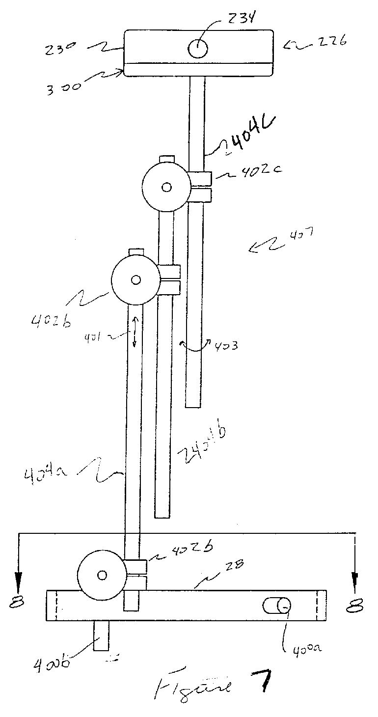
- FIG. 7 An alternate embodiment of an apparatus according to the present invention is shown in Figures 7 and 8.
- the rocker arm 28 includes reference device attachment structures such as cylindrical mounting bosses 400a, 400b, 400c. Of course, the number and location of bosses may be varied as desired. Through holes 206 and mounting bosses 400 may both be included on the rocker arm 28 to provide additional flexibility.
- An adjustable mounting structure 407 facilitates adjustment of the position and orientation of the reference object 226 in relation to the rocker arm 28.
- a first adjustable mounting clamp 402a engages one of the mounting bosses, for example mounting boss 400c.
- the mounting clamp 402a also engages a first rigid cylindrical extension rod 404a.
- a second mounting clamp 402 also engages the first cylindrical extension rod 404a.
- the second mounting clamp 402b in turn engages a second rigid cylindrical extension rod 404b.
- a third mounting clamp 402c also engages the second rod 404b.
- the third mounting clamp 402c in turn engages a third rigid cylindrical mounting rod 404c. Threads on rod 404c engage the threaded aperture 232 on the bottom of the reference object 226.
- the mounting clamps 402 function as joints which allow the position of the rods 404 to be adjusted.
- the clamps 402 preferably allow a variety of degrees of motion.
- the clamps 402 allow the rods 404 inserted therein to be moved longitudinally in the direction of arrow 401.
- the clamps 402 also allow relative rotation of the rods 404 and clamps 402 about the longitudinal axis of the rods 404 as indicated by arrow 403.
- the clamps 402 also permit relative pivotal motion of the rods 404 inserted therein the direction of arrows 405.
- the position and orientation of the reference object 226 may be readily adjusted.
- the mounting structure is illustrated with three rods 404 and associated clamps 402, the rods 202 are readily insertable in and removable from the clamps 402 such that greater and lesser numbers of rods may be used, further enhancing the adjustability of the reference object 226 in relation to the rocker arm 28.
- rods of different lengths or configurations i.e. having bends or curves
- the adjustable mounting structure 407 is usable in connection with devices other than the rocker arm 28 and the reference object 226.
- the mounting structure 407 may be used to allow relative positioning between a reference object and a surgical microscope, or to allow positioning of a surgical tool in relation to a stationary structure.
- a clamp 402 has a clamp body 500 having orthogonal, non-intersecting apertures 502 and 504.
- Aperture 502 accepts a rod 202 for insertion therethrough, while aperture 504 accepts a rod-engaging member 506.
- the rod-engaging member 506 also contains an aperture 508 which accepts a rod 202 for insertion therethrough.
- a thumb screw 510 engages threads 512 on the rod-engaging member 506.
- the thumbscrew also includes a hexagonal extension 524.
- a v-shaped groove on a rod-holding member 514 frictionally engages a rod 202 inserted in the aperture 508.
- Both the rod-engaging member 506 and the rod-holding member 516 are rotatable within the aperture 504 about axis 518 as indicated by the arrows.
- a spring 520 placed in compression urges the thumb screw 510 and hence the rod-engaging member 506 downward so that the aperture 508 is urged toward the clamp body 500.
- the end of the rod-engaging member 506 is sized to prevent the member 506 from being urged all the way through the aperture 504.
- a washer 522 is disposed between the spring 520 and the clamp body 500.
- the clamps 402 thus permit the positions of rods 202 inserted in the apertures 508 and 502 to be selectively adjusted.
- a rod 202 inserted in the aperture 502 is movable along its longitudinal axis through the aperture 502 as indicated by arrows 206.
- the rod 202 is also rotatable within the aperture 502 in the direction indicated by arrows 403.
- a rod 202 inserted in the aperture 508 is movable along its longitudinal axis through the aperture 502 in the direction of arrows 401.
- the rod 202 is also rotatable within the aperture 508 in the direction indicated by arrows 405.
- the rods may also be pivotally adjusted relative to each other as indicated by arrow 405.
- rods inserted in the apertures 508 and 502 may be readily removed from and inserted in the apertures. Tightening the thumb screw 504 holds the rods 202 more securely in place.
- the clamp 502 may also be tightened more firmly using a tool in conjunction with hexagonal extension 524.
- the reference object 226 is attached to the rocker arm 28 and its position adjusted to provide reliable communication between the emitters 228a-228d and the localizer and so that the reference object and the associated supporting structure does not interfere with the activities of the surgeon.
- the patient and operating room reference frames are initially correlated by touching the tip of a the surgical tool to the fiducial markers to determine their position.
- the position and orientation of the reference object 226 is monitored by the localizer.
- the patient and operating room reference frames may be automatically re-correlated by the image guided surgery system computer to account for changes in the position of the reference object.
- the system automatically accounts for changes in the position of the patient.
Abstract
Description
Claims (32)
- A position signaling apparatus for use with a surgical head clamp, which head clamp includes a frame and a first head engaging pin secured to one side of the frame, the apparatus comprising: pin holding means mountable to an opposite side of the frame, the pin holding means adapted to support second and third head engaging pins mountable thereon; a position signaling device supported by the pin holding means, the signaling device being adapted for operative communication with an image guided surgery system.
- Apparatus as claimed in claim 1, wherein the position of the position signaling device in relation to the pin holding means is selectively adjustable.
- Apparatus as claimed in claim 1 or claim 2, comprising means for attaching the signaling device to the pin holding means.
- Apparatus as claimed in claim 3, wherein the means for attaching comprises a clamp attached to the pin holding means.
- Apparatus as claimed in any one of claims 1 to 4, further comprising an adjustable support structure which attaches the position signaling device to the pin holding means, the adjustable support structure comprising: first and second members; a joint which connects the first and second members, the joint selectively allowing relative pivotal motion therebetween.
- Apparatus as claimed in claim 5, wherein the first member defines a first longitudinal axis and the joint selectively allows relative motion of the joint and the first member along the first longitudinal axis.
- Apparatus as claimed in claim 6, wherein the second member defines a second longitudinal axis and the joint selectively allows relative motion of the joint and the second member along the second longitudinal axis.
- Apparatus as claimed in claim 7, wherein the joint selectively allows relative rotational motion of the first member and the joint about the first longitudinal axis.
- Apparatus as claimed in any one of claims 5 to 8, comprising a third member and a second joint interconnecting the second and third members, the joint selectively allowing relative pivotal motion therebetween.
- Apparatus as claimed in any one of claims 5 to 9, wherein the members comprise rigid, cylindrical rods.
- Apparatus as claimed in any one of claims 5 to 10, wherein the joint comprises a clamp.
- Apparatus as claimed in any one of claims 1 to 11, wherein the pin holding means comprises a mounting boss and the position signaling device is supported by the mounting boss.
- Apparatus as claimed in any one of claims 1 to 12, wherein the position signaling device comprises a plurality of infrared emitters.
- A method of determining the position of an object disposed in a surgical head clamp, the head clamp including a frame, a first head engaging pin secured to one side of the frame, and a pin holding means mounted to an opposite side of the frame, the pin holding means supporting second and third head engaging pins mounted to the pin holding means, the method comprising the steps of: mounting a position signaling device to the pin holding means, the position signaling device adapted for operative communication with an image guided surgery system; and using the image guided surgery system to determine the position of the position signaling device.
- A method as claimed in claim 14, wherein the position signaling device is connected to a support and further comprising the step of clamping the support to the pin holding means.
- A method as claimed in claim 14 or claim 15, wherein the pin holding means comprises a mounting boss and the support structure is clamped to the mounting boss.
- A method as claimed in any one of claim 14 to 16, wherein the position signaling device is connected to a support structure having an end. the pin holding means comprises a through hole, and the step of mounting comprises inserting the end of the support member into the through hole.
- A method as claimed in any one of claims 14 to 17, wherein the pin holding means comprises a mounting boss and the step of mounting comprises: connecting a first rod to the mounting boss; connecting a second rod to the first rod, the first and second rods being selectively movable with respect to each other; connecting the second rod to a third rod, the second and third rods being selectively movable with respect to each other; connecting the third rod to the position signaling device; adjusting the position of the signaling device in relation to the pin holding means.
- An apparatus for determining the position of an object disposed in a clamp, the clamp including a frame, a first object engaging pin disposed on one side of the frame, and pin holding means movably mounted to an opposite side of the frame, the pin holding means adapted to support second and third object engaging pins mounted thereon, the apparatus comprising: a position signaling device disposed in fixed relation to the pin holding means for movement therewith; means for determining the position of the position signaling device.
- Apparatus as claimed in claim 19, wherein the position of the position signaling device in relation to the pin holding means is selectively adjustable.
- Apparatus as claimed in claim 19 or claim 20, wherein the means for determining comprises an infrared localizer.
- Apparatus as claimed in any one of claims 19 to 21, comprising a mounting structure which attaches the position signaling device to the pin holding means, the mounting structure comprising a plurality of connected cylindrical rods having longitudinal axes, the connections selectively allowing the rods to be rotated about their longitudinal axes, the connections further selectively allowing relative pivotal motion of adjacent connected rods.
- Apparatus as claimed in claim 22, wherein the connections selectively allow the rods to be moved along their longitudinal axes.
- A position signaling apparatus for use with an image guided surgery system, the apparatus comprising: a position signaling device adapted for operative communication with the image guided surgery system; and an adjustable support structure comprising a first member connected to the position signaling device; a second member; a joint disposed between and connecting the first member and the second member, the joint selectively allowing relative pivotal motion of the first and second members.
- Apparatus as claimed in claim 24, wherein the second member may be readily disconnected from and connected to the first member.
- Apparatus as claimed in claim 24 or claim 25, wherein the first member has a longitudinal axis and the joint is adapted to selectively allow relative rotational motion of the joint and the first member about the longitudinal axis.
- Apparatus as claimed in any one of claims 24 to 26, wherein the second member has a longitudinal axis and the joint is adapted to selectively allow relative rotational motion of the joint and the second member about the longitudinal axis of the second member.
- Apparatus as claimed in any one of claims 24 to 27, wherein the joint is adapted to selectively allow relative motion of the second member and the joint along the longitudinal axis of the second member.
- Apparatus as claimed in any one of claims 24 to 28, wherein joint is adapted to selectively allow relative motion of the first member and the joint along the longitudinal axis.
- Apparatus as claimed in any one of claims 24 to 29, further comprising a third member; a joint disposed between and connecting the second member and the third member, the joint selectively allowing relative pivotal motion of the second and third members.
- Apparatus as claimed in any one of claims 24 to 30, wherein the position signaling device comprises a threaded aperture and the first member comprises a cylindrical rod adapted to engage the threaded aperture.
- Apparatus as claimed in any one of claims 24 to 31, wherein the joint comprises a clamp having a thumb screw.
Applications Claiming Priority (2)
| Application Number | Priority Date | Filing Date | Title |
|---|---|---|---|
| US2740296P | 1996-09-30 | 1996-09-30 | |
| US27402P | 1996-09-30 |
Publications (2)
| Publication Number | Publication Date |
|---|---|
| EP0832609A2 true EP0832609A2 (en) | 1998-04-01 |
| EP0832609A3 EP0832609A3 (en) | 1999-06-16 |
Family
ID=21837533
Family Applications (1)
| Application Number | Title | Priority Date | Filing Date |
|---|---|---|---|
| EP97307554A Withdrawn EP0832609A3 (en) | 1996-09-30 | 1997-09-26 | Position tracking |
Country Status (2)
| Country | Link |
|---|---|
| US (2) | US5980535A (en) |
| EP (1) | EP0832609A3 (en) |
Cited By (9)
| Publication number | Priority date | Publication date | Assignee | Title |
|---|---|---|---|---|
| WO1999015097A3 (en) * | 1997-09-24 | 1999-06-17 | Surgical Navigation Tech | Percutaneous registration apparatus and method for use in computer-assisted surgical navigation |
| FR2779339A1 (en) * | 1998-06-09 | 1999-12-10 | Integrated Surgical Systems Sa | MATCHING METHOD AND APPARATUS FOR ROBOTIC SURGERY, AND MATCHING DEVICE COMPRISING APPLICATION |
| WO1999066853A1 (en) * | 1998-06-22 | 1999-12-29 | Synthes Ag Chur | Fiducial matching by means of fiducial screws |
| WO2004030558A1 (en) * | 2002-10-04 | 2004-04-15 | Orthosoft Inc. | Cas bone reference with articulated support |
| US6725082B2 (en) | 1999-03-17 | 2004-04-20 | Synthes U.S.A. | System and method for ligament graft placement |
| US20100256520A1 (en) * | 2005-12-09 | 2010-10-07 | Senorx, Inc. | Guide block for biopsy or surgical devices |
| US7840256B2 (en) | 2005-06-27 | 2010-11-23 | Biomet Manufacturing Corporation | Image guided tracking array and method |
| US8571637B2 (en) | 2008-01-21 | 2013-10-29 | Biomet Manufacturing, Llc | Patella tracking method and apparatus for use in surgical navigation |
| WO2019153096A1 (en) * | 2018-02-07 | 2019-08-15 | Ao Technology Ag | Reference device for real-time tracking of bone and/or surgical objects in computer-assisted surgery |
Families Citing this family (190)
| Publication number | Priority date | Publication date | Assignee | Title |
|---|---|---|---|---|
| FR2652928B1 (en) | 1989-10-05 | 1994-07-29 | Diadix Sa | INTERACTIVE LOCAL INTERVENTION SYSTEM WITHIN A AREA OF A NON-HOMOGENEOUS STRUCTURE. |
| WO1994004938A1 (en) | 1992-08-14 | 1994-03-03 | British Telecommunications Public Limited Company | Position location system |
| US5803089A (en) | 1994-09-15 | 1998-09-08 | Visualization Technology, Inc. | Position tracking and imaging system for use in medical applications |
| US5592939A (en) | 1995-06-14 | 1997-01-14 | Martinelli; Michael A. | Method and system for navigating a catheter probe |
| US6226418B1 (en) | 1997-11-07 | 2001-05-01 | Washington University | Rapid convolution based large deformation image matching via landmark and volume imagery |
| US6408107B1 (en) | 1996-07-10 | 2002-06-18 | Michael I. Miller | Rapid convolution based large deformation image matching via landmark and volume imagery |
| US6611630B1 (en) | 1996-07-10 | 2003-08-26 | Washington University | Method and apparatus for automatic shape characterization |
| US6009212A (en) | 1996-07-10 | 1999-12-28 | Washington University | Method and apparatus for image registration |
| US6708184B2 (en) | 1997-04-11 | 2004-03-16 | Medtronic/Surgical Navigation Technologies | Method and apparatus for producing and accessing composite data using a device having a distributed communication controller interface |
| US5970499A (en) | 1997-04-11 | 1999-10-19 | Smith; Kurt R. | Method and apparatus for producing and accessing composite data |
| US6752812B1 (en) | 1997-05-15 | 2004-06-22 | Regent Of The University Of Minnesota | Remote actuation of trajectory guide |
| US6434507B1 (en) * | 1997-09-05 | 2002-08-13 | Surgical Navigation Technologies, Inc. | Medical instrument and method for use with computer-assisted image guided surgery |
| US5999837A (en) * | 1997-09-26 | 1999-12-07 | Picker International, Inc. | Localizing and orienting probe for view devices |
| US6021343A (en) | 1997-11-20 | 2000-02-01 | Surgical Navigation Technologies | Image guided awl/tap/screwdriver |
| US6348058B1 (en) | 1997-12-12 | 2002-02-19 | Surgical Navigation Technologies, Inc. | Image guided spinal surgery guide, system, and method for use thereof |
| US6118845A (en) | 1998-06-29 | 2000-09-12 | Surgical Navigation Technologies, Inc. | System and methods for the reduction and elimination of image artifacts in the calibration of X-ray imagers |
| US6459927B1 (en) | 1999-07-06 | 2002-10-01 | Neutar, Llc | Customizable fixture for patient positioning |
| US6327491B1 (en) * | 1998-07-06 | 2001-12-04 | Neutar, Llc | Customized surgical fixture |
| US6477400B1 (en) | 1998-08-20 | 2002-11-05 | Sofamor Danek Holdings, Inc. | Fluoroscopic image guided orthopaedic surgery system with intraoperative registration |
| US6482182B1 (en) | 1998-09-03 | 2002-11-19 | Surgical Navigation Technologies, Inc. | Anchoring system for a brain lead |
| US6195577B1 (en) | 1998-10-08 | 2001-02-27 | Regents Of The University Of Minnesota | Method and apparatus for positioning a device in a body |
| US6340363B1 (en) | 1998-10-09 | 2002-01-22 | Surgical Navigation Technologies, Inc. | Image guided vertebral distractor and method for tracking the position of vertebrae |
| DE19848765C2 (en) | 1998-10-22 | 2000-12-21 | Brainlab Med Computersyst Gmbh | Position verification in camera images |
| US6285902B1 (en) | 1999-02-10 | 2001-09-04 | Surgical Insights, Inc. | Computer assisted targeting device for use in orthopaedic surgery |
| US6470207B1 (en) | 1999-03-23 | 2002-10-22 | Surgical Navigation Technologies, Inc. | Navigational guidance via computer-assisted fluoroscopic imaging |
| US6491699B1 (en) | 1999-04-20 | 2002-12-10 | Surgical Navigation Technologies, Inc. | Instrument guidance method and system for image guided surgery |
| DE19917867B4 (en) | 1999-04-20 | 2005-04-21 | Brainlab Ag | Method and device for image support in the treatment of treatment objectives with integration of X-ray detection and navigation system |
| CA2370960C (en) | 1999-04-20 | 2006-06-13 | Synthes (U.S.A.) | Device for the percutaneous obtainment of 3d-coordinates on the surface of a human or animal organ |
| US6306132B1 (en) * | 1999-06-17 | 2001-10-23 | Vivant Medical | Modular biopsy and microwave ablation needle delivery apparatus adapted to in situ assembly and method of use |
| US6474341B1 (en) | 1999-10-28 | 2002-11-05 | Surgical Navigation Technologies, Inc. | Surgical communication and power system |
| US8239001B2 (en) | 2003-10-17 | 2012-08-07 | Medtronic Navigation, Inc. | Method and apparatus for surgical navigation |
| US6493573B1 (en) | 1999-10-28 | 2002-12-10 | Winchester Development Associates | Method and system for navigating a catheter probe in the presence of field-influencing objects |
| US6235038B1 (en) | 1999-10-28 | 2001-05-22 | Medtronic Surgical Navigation Technologies | System for translation of electromagnetic and optical localization systems |
| US6379302B1 (en) | 1999-10-28 | 2002-04-30 | Surgical Navigation Technologies Inc. | Navigation information overlay onto ultrasound imagery |
| US11331150B2 (en) | 1999-10-28 | 2022-05-17 | Medtronic Navigation, Inc. | Method and apparatus for surgical navigation |
| US6499488B1 (en) | 1999-10-28 | 2002-12-31 | Winchester Development Associates | Surgical sensor |
| US7366562B2 (en) | 2003-10-17 | 2008-04-29 | Medtronic Navigation, Inc. | Method and apparatus for surgical navigation |
| US8644907B2 (en) | 1999-10-28 | 2014-02-04 | Medtronic Navigaton, Inc. | Method and apparatus for surgical navigation |
| US6381485B1 (en) | 1999-10-28 | 2002-04-30 | Surgical Navigation Technologies, Inc. | Registration of human anatomy integrated for electromagnetic localization |
| AU2001238382A1 (en) * | 2000-02-18 | 2001-08-27 | Thomas J. M. D. Fogarty | Improved device for accurately marking tissue |
| WO2001064124A1 (en) * | 2000-03-01 | 2001-09-07 | Surgical Navigation Technologies, Inc. | Multiple cannula image guided tool for image guided procedures |
| US7660621B2 (en) | 2000-04-07 | 2010-02-09 | Medtronic, Inc. | Medical device introducer |
| US6535756B1 (en) | 2000-04-07 | 2003-03-18 | Surgical Navigation Technologies, Inc. | Trajectory storage apparatus and method for surgical navigation system |
| US7366561B2 (en) | 2000-04-07 | 2008-04-29 | Medtronic, Inc. | Robotic trajectory guide |
| US6478802B2 (en) | 2000-06-09 | 2002-11-12 | Ge Medical Systems Global Technology Company, Llc | Method and apparatus for display of an image guided drill bit |
| US7085400B1 (en) | 2000-06-14 | 2006-08-01 | Surgical Navigation Technologies, Inc. | System and method for image based sensor calibration |
| US6902569B2 (en) | 2000-08-17 | 2005-06-07 | Image-Guided Neurologics, Inc. | Trajectory guide with instrument immobilizer |
| US6636757B1 (en) * | 2001-06-04 | 2003-10-21 | Surgical Navigation Technologies, Inc. | Method and apparatus for electromagnetic navigation of a surgical probe near a metal object |
| JP4387611B2 (en) * | 2001-06-07 | 2009-12-16 | 富士通マイクロエレクトロニクス株式会社 | Drawing apparatus and drawing method |
| US6887245B2 (en) * | 2001-06-11 | 2005-05-03 | Ge Medical Systems Global Technology Company, Llc | Surgical drill for use with a computer assisted surgery system |
| US6584339B2 (en) * | 2001-06-27 | 2003-06-24 | Vanderbilt University | Method and apparatus for collecting and processing physical space data for use while performing image-guided surgery |
| US6878147B2 (en) | 2001-11-02 | 2005-04-12 | Vivant Medical, Inc. | High-strength microwave antenna assemblies |
| US7128739B2 (en) * | 2001-11-02 | 2006-10-31 | Vivant Medical, Inc. | High-strength microwave antenna assemblies and methods of use |
| JP2005516724A (en) * | 2002-02-11 | 2005-06-09 | スミス アンド ネフュー インコーポレーテッド | Image guided fracture reduction |
| US6947786B2 (en) | 2002-02-28 | 2005-09-20 | Surgical Navigation Technologies, Inc. | Method and apparatus for perspective inversion |
| US8996169B2 (en) | 2011-12-29 | 2015-03-31 | Mako Surgical Corp. | Neural monitor-based dynamic haptics |
| US11202676B2 (en) | 2002-03-06 | 2021-12-21 | Mako Surgical Corp. | Neural monitor-based dynamic haptics |
| US7831292B2 (en) * | 2002-03-06 | 2010-11-09 | Mako Surgical Corp. | Guidance system and method for surgical procedures with improved feedback |
| US8010180B2 (en) | 2002-03-06 | 2011-08-30 | Mako Surgical Corp. | Haptic guidance system and method |
| US7747311B2 (en) * | 2002-03-06 | 2010-06-29 | Mako Surgical Corp. | System and method for interactive haptic positioning of a medical device |
| GB0206131D0 (en) * | 2002-03-15 | 2002-04-24 | Depuy Int Ltd | A surgical navigation tool |
| US6990368B2 (en) | 2002-04-04 | 2006-01-24 | Surgical Navigation Technologies, Inc. | Method and apparatus for virtual digital subtraction angiography |
| US7197363B2 (en) | 2002-04-16 | 2007-03-27 | Vivant Medical, Inc. | Microwave antenna having a curved configuration |
| US6752767B2 (en) | 2002-04-16 | 2004-06-22 | Vivant Medical, Inc. | Localization element with energized tip |
| US7998062B2 (en) | 2004-03-29 | 2011-08-16 | Superdimension, Ltd. | Endoscope structures and techniques for navigating to a target in branched structure |
| US7213598B2 (en) * | 2002-05-28 | 2007-05-08 | Brainlab Ag | Navigation-calibrating rotationally asymmetrical medical instruments or implants |
| US7769427B2 (en) * | 2002-07-16 | 2010-08-03 | Magnetics, Inc. | Apparatus and method for catheter guidance control and imaging |
| US7704260B2 (en) | 2002-09-17 | 2010-04-27 | Medtronic, Inc. | Low profile instrument immobilizer |
| US8034057B2 (en) * | 2002-11-07 | 2011-10-11 | Penenberg Brad L | Apparatus for, and method of, preparing for and inserting hip joint prosthesis using computer guidance |
| WO2004046754A2 (en) * | 2002-11-14 | 2004-06-03 | General Electric Medical Systems Global Technology Company, Llc | Interchangeable localizing devices for use with tracking systems |
| US7599730B2 (en) | 2002-11-19 | 2009-10-06 | Medtronic Navigation, Inc. | Navigation system for cardiac therapies |
| US7697972B2 (en) | 2002-11-19 | 2010-04-13 | Medtronic Navigation, Inc. | Navigation system for cardiac therapies |
| US7094241B2 (en) * | 2002-11-27 | 2006-08-22 | Zimmer Technology, Inc. | Method and apparatus for achieving correct limb alignment in unicondylar knee arthroplasty |
| US20040122305A1 (en) * | 2002-12-20 | 2004-06-24 | Grimm James E. | Surgical instrument and method of positioning same |
| US7636596B2 (en) | 2002-12-20 | 2009-12-22 | Medtronic, Inc. | Organ access device and method |
| US7029477B2 (en) | 2002-12-20 | 2006-04-18 | Zimmer Technology, Inc. | Surgical instrument and positioning method |
| US20070282347A9 (en) * | 2002-12-20 | 2007-12-06 | Grimm James E | Navigated orthopaedic guide and method |
| US20040172044A1 (en) * | 2002-12-20 | 2004-09-02 | Grimm James E. | Surgical instrument and method of positioning same |
| US7542791B2 (en) | 2003-01-30 | 2009-06-02 | Medtronic Navigation, Inc. | Method and apparatus for preplanning a surgical procedure |
| US7660623B2 (en) | 2003-01-30 | 2010-02-09 | Medtronic Navigation, Inc. | Six degree of freedom alignment display for medical procedures |
| US6988009B2 (en) * | 2003-02-04 | 2006-01-17 | Zimmer Technology, Inc. | Implant registration device for surgical navigation system |
| US20040152955A1 (en) * | 2003-02-04 | 2004-08-05 | Mcginley Shawn E. | Guidance system for rotary surgical instrument |
| US20040171930A1 (en) * | 2003-02-04 | 2004-09-02 | Zimmer Technology, Inc. | Guidance system for rotary surgical instrument |
| US7458977B2 (en) * | 2003-02-04 | 2008-12-02 | Zimmer Technology, Inc. | Surgical navigation instrument useful in marking anatomical structures |
| EP1627272B2 (en) * | 2003-02-04 | 2017-03-08 | Mako Surgical Corp. | Interactive computer-assisted surgery system and method |
| US6925339B2 (en) | 2003-02-04 | 2005-08-02 | Zimmer Technology, Inc. | Implant registration device for surgical navigation system |
| US7896889B2 (en) | 2003-02-20 | 2011-03-01 | Medtronic, Inc. | Trajectory guide with angled or patterned lumens or height adjustment |
| FR2852223B1 (en) * | 2003-03-11 | 2005-06-10 | Perception Raisonnement Action En Medecine | INSTRUMENT FOR TRACKING THE POSITION OF A CUTTING PLAN |
| US20050021037A1 (en) * | 2003-05-29 | 2005-01-27 | Mccombs Daniel L. | Image-guided navigated precision reamers |
| US6932823B2 (en) * | 2003-06-24 | 2005-08-23 | Zimmer Technology, Inc. | Detachable support arm for surgical navigation system reference array |
| US20040267256A1 (en) * | 2003-06-24 | 2004-12-30 | Garabedian Robert J. | Compound lesion alignment device |
| US7311703B2 (en) * | 2003-07-18 | 2007-12-25 | Vivant Medical, Inc. | Devices and methods for cooling microwave antennas |
| US20050049485A1 (en) * | 2003-08-27 | 2005-03-03 | Harmon Kim R. | Multiple configuration array for a surgical navigation system |
| US7313430B2 (en) | 2003-08-28 | 2007-12-25 | Medtronic Navigation, Inc. | Method and apparatus for performing stereotactic surgery |
| EP2316328B1 (en) | 2003-09-15 | 2012-05-09 | Super Dimension Ltd. | Wrap-around holding device for use with bronchoscopes |
| WO2005025635A2 (en) | 2003-09-15 | 2005-03-24 | Super Dimension Ltd. | System of accessories for use with bronchoscopes |
| US7862570B2 (en) | 2003-10-03 | 2011-01-04 | Smith & Nephew, Inc. | Surgical positioners |
| US7835778B2 (en) | 2003-10-16 | 2010-11-16 | Medtronic Navigation, Inc. | Method and apparatus for surgical navigation of a multiple piece construct for implantation |
| US7840253B2 (en) | 2003-10-17 | 2010-11-23 | Medtronic Navigation, Inc. | Method and apparatus for surgical navigation |
| US7764985B2 (en) | 2003-10-20 | 2010-07-27 | Smith & Nephew, Inc. | Surgical navigation system component fault interfaces and related processes |
| US7280863B2 (en) * | 2003-10-20 | 2007-10-09 | Magnetecs, Inc. | System and method for radar-assisted catheter guidance and control |
| EP1691692B1 (en) * | 2003-11-14 | 2011-01-19 | Smith & Nephew, Inc. | Adjustable surgical cutting systems |
| US7641661B2 (en) | 2003-12-26 | 2010-01-05 | Zimmer Technology, Inc. | Adjustable resection guide |
| US8764725B2 (en) | 2004-02-09 | 2014-07-01 | Covidien Lp | Directional anchoring mechanism, method and applications thereof |
| US20050182420A1 (en) | 2004-02-13 | 2005-08-18 | Schulte Gregory T. | Low profile apparatus for securing a therapy delivery device within a burr hole |
| US8046050B2 (en) * | 2004-03-05 | 2011-10-25 | Biosense Webster, Inc. | Position sensing system for orthopedic applications |
| US20050215888A1 (en) * | 2004-03-05 | 2005-09-29 | Grimm James E | Universal support arm and tracking array |
| US20060052691A1 (en) * | 2004-03-05 | 2006-03-09 | Hall Maleata Y | Adjustable navigated tracking element mount |
| US7641660B2 (en) | 2004-03-08 | 2010-01-05 | Biomet Manufacturing Corporation | Method, apparatus, and system for image guided bone cutting |
| US8114086B2 (en) * | 2004-03-08 | 2012-02-14 | Zimmer Technology, Inc. | Navigated cut guide locator |
| US7993341B2 (en) * | 2004-03-08 | 2011-08-09 | Zimmer Technology, Inc. | Navigated orthopaedic guide and method |
| WO2005104978A1 (en) | 2004-04-21 | 2005-11-10 | Smith & Nephew, Inc. | Computer-aided methods, systems, and apparatuses for shoulder arthroplasty |
| US7567834B2 (en) | 2004-05-03 | 2009-07-28 | Medtronic Navigation, Inc. | Method and apparatus for implantation between two vertebral bodies |
| US8167888B2 (en) * | 2004-08-06 | 2012-05-01 | Zimmer Technology, Inc. | Tibial spacer blocks and femoral cutting guide |
| JP4709996B2 (en) * | 2004-09-14 | 2011-06-29 | 国立大学法人大阪大学 | Bone tracking device fixation member |
| US20060089626A1 (en) * | 2004-10-22 | 2006-04-27 | Vlegele James W | Surgical device guide for use with an imaging system |
| US7452357B2 (en) * | 2004-10-22 | 2008-11-18 | Ethicon Endo-Surgery, Inc. | System and method for planning treatment of tissue |
| US7833221B2 (en) * | 2004-10-22 | 2010-11-16 | Ethicon Endo-Surgery, Inc. | System and method for treatment of tissue using the tissue as a fiducial |
| US7497863B2 (en) | 2004-12-04 | 2009-03-03 | Medtronic, Inc. | Instrument guiding stage apparatus and method for using same |
| US7744606B2 (en) | 2004-12-04 | 2010-06-29 | Medtronic, Inc. | Multi-lumen instrument guide |
| US20060161059A1 (en) * | 2005-01-20 | 2006-07-20 | Zimmer Technology, Inc. | Variable geometry reference array |
| JP2008531091A (en) | 2005-02-22 | 2008-08-14 | スミス アンド ネフュー インコーポレーテッド | In-line milling system |
| US7799019B2 (en) | 2005-05-10 | 2010-09-21 | Vivant Medical, Inc. | Reinforced high strength microwave antenna |
| US8027714B2 (en) * | 2005-05-27 | 2011-09-27 | Magnetecs, Inc. | Apparatus and method for shaped magnetic field control for catheter, guidance, control, and imaging |
| US20070073136A1 (en) * | 2005-09-15 | 2007-03-29 | Robert Metzger | Bone milling with image guided surgery |
| US7643862B2 (en) | 2005-09-15 | 2010-01-05 | Biomet Manufacturing Corporation | Virtual mouse for use in surgical navigation |
| US7835784B2 (en) | 2005-09-21 | 2010-11-16 | Medtronic Navigation, Inc. | Method and apparatus for positioning a reference frame |
| US20070149977A1 (en) * | 2005-11-28 | 2007-06-28 | Zimmer Technology, Inc. | Surgical component positioner |
| US7520880B2 (en) * | 2006-01-09 | 2009-04-21 | Zimmer Technology, Inc. | Adjustable surgical support base with integral hinge |
| US7744600B2 (en) * | 2006-01-10 | 2010-06-29 | Zimmer Technology, Inc. | Bone resection guide and method |
| US9168102B2 (en) | 2006-01-18 | 2015-10-27 | Medtronic Navigation, Inc. | Method and apparatus for providing a container to a sterile environment |
| US7780671B2 (en) * | 2006-01-23 | 2010-08-24 | Zimmer Technology, Inc. | Bone resection apparatus and method for knee surgery |
| US20070233156A1 (en) * | 2006-02-16 | 2007-10-04 | Robert Metzger | Surgical instrument |
| US20070239153A1 (en) * | 2006-02-22 | 2007-10-11 | Hodorek Robert A | Computer assisted surgery system using alternative energy technology |
| US7869854B2 (en) * | 2006-02-23 | 2011-01-11 | Magnetecs, Inc. | Apparatus for magnetically deployable catheter with MOSFET sensor and method for mapping and ablation |
| US8323290B2 (en) * | 2006-03-03 | 2012-12-04 | Biomet Manufacturing Corp. | Tensor for use in surgical navigation |
| US8112292B2 (en) | 2006-04-21 | 2012-02-07 | Medtronic Navigation, Inc. | Method and apparatus for optimizing a therapy |
| EP1854425A1 (en) | 2006-05-11 | 2007-11-14 | BrainLAB AG | Position determination for medical devices with redundant position measurement and weighting to prioritise measurements |
| JP2009537231A (en) | 2006-05-19 | 2009-10-29 | マコ サージカル コーポレーション | Method and apparatus for controlling a haptic device |
| US8660635B2 (en) | 2006-09-29 | 2014-02-25 | Medtronic, Inc. | Method and apparatus for optimizing a computer assisted surgical procedure |
| US8068921B2 (en) * | 2006-09-29 | 2011-11-29 | Vivant Medical, Inc. | Microwave antenna assembly and method of using the same |
| US20080161824A1 (en) * | 2006-12-27 | 2008-07-03 | Howmedica Osteonics Corp. | System and method for performing femoral sizing through navigation |
| US20080163118A1 (en) * | 2006-12-29 | 2008-07-03 | Jason Wolf | Representation of file relationships |
| US20080249395A1 (en) * | 2007-04-06 | 2008-10-09 | Yehoshua Shachar | Method and apparatus for controlling catheter positioning and orientation |
| US7998139B2 (en) | 2007-04-25 | 2011-08-16 | Vivant Medical, Inc. | Cooled helical antenna for microwave ablation |
| US8934961B2 (en) | 2007-05-18 | 2015-01-13 | Biomet Manufacturing, Llc | Trackable diagnostic scope apparatus and methods of use |
| US8353901B2 (en) * | 2007-05-22 | 2013-01-15 | Vivant Medical, Inc. | Energy delivery conduits for use with electrosurgical devices |
| US20080297287A1 (en) * | 2007-05-30 | 2008-12-04 | Magnetecs, Inc. | Magnetic linear actuator for deployable catheter tools |
| US9023024B2 (en) | 2007-06-20 | 2015-05-05 | Covidien Lp | Reflective power monitoring for microwave applications |
| US20090005766A1 (en) * | 2007-06-28 | 2009-01-01 | Joseph Brannan | Broadband microwave applicator |
| US8905920B2 (en) | 2007-09-27 | 2014-12-09 | Covidien Lp | Bronchoscope adapter and method |
| US8651146B2 (en) | 2007-09-28 | 2014-02-18 | Covidien Lp | Cable stand-off |
| US8292880B2 (en) | 2007-11-27 | 2012-10-23 | Vivant Medical, Inc. | Targeted cooling of deployable microwave antenna |
| US20090163930A1 (en) * | 2007-12-19 | 2009-06-25 | Ahmed Aoude | Calibration system of a computer-assisted surgery system |
| US9575140B2 (en) | 2008-04-03 | 2017-02-21 | Covidien Lp | Magnetic interference detection system and method |
| US20090275828A1 (en) * | 2008-05-01 | 2009-11-05 | Magnetecs, Inc. | Method and apparatus for creating a high resolution map of the electrical and mechanical properties of the heart |
| US20090285356A1 (en) * | 2008-05-16 | 2009-11-19 | Sirona Dental Systems Gmbh | System and method for patient positioning in cone-beam tomography |
| EP2297673B1 (en) | 2008-06-03 | 2020-04-22 | Covidien LP | Feature-based registration method |
| US8218847B2 (en) | 2008-06-06 | 2012-07-10 | Superdimension, Ltd. | Hybrid registration method |
| US8932207B2 (en) | 2008-07-10 | 2015-01-13 | Covidien Lp | Integrated multi-functional endoscopic tool |
| US8165658B2 (en) | 2008-09-26 | 2012-04-24 | Medtronic, Inc. | Method and apparatus for positioning a guide relative to a base |
| US8457714B2 (en) * | 2008-11-25 | 2013-06-04 | Magnetecs, Inc. | System and method for a catheter impedance seeking device |
| US8175681B2 (en) | 2008-12-16 | 2012-05-08 | Medtronic Navigation Inc. | Combination of electromagnetic and electropotential localization |
| US8611984B2 (en) | 2009-04-08 | 2013-12-17 | Covidien Lp | Locatable catheter |
| US8494613B2 (en) | 2009-08-31 | 2013-07-23 | Medtronic, Inc. | Combination localization system |
| US8494614B2 (en) | 2009-08-31 | 2013-07-23 | Regents Of The University Of Minnesota | Combination localization system |
| US20110091853A1 (en) * | 2009-10-20 | 2011-04-21 | Magnetecs, Inc. | Method for simulating a catheter guidance system for control, development and training applications |
| US20110092808A1 (en) * | 2009-10-20 | 2011-04-21 | Magnetecs, Inc. | Method for acquiring high density mapping data with a catheter guidance system |
| US20110112396A1 (en) * | 2009-11-09 | 2011-05-12 | Magnetecs, Inc. | System and method for targeting catheter electrodes |
| US20110213247A1 (en) * | 2010-01-08 | 2011-09-01 | Hexagon Metrology, Inc. | Articulated arm with imaging device |
| JP2013523415A (en) * | 2010-04-14 | 2013-06-17 | スミス アンド ネフュー インコーポレーテッド | System and method for patient-assisted computer-assisted surgical procedure |
| WO2011159834A1 (en) | 2010-06-15 | 2011-12-22 | Superdimension, Ltd. | Locatable expandable working channel and method |
| US8945011B2 (en) * | 2011-04-05 | 2015-02-03 | Houston Medical Robotics, Inc. | Systems and methods for accessing the lumen of a vessel |
| WO2013134623A1 (en) | 2012-03-08 | 2013-09-12 | Neutar, Llc | Patient and procedure customized fixation and targeting devices for stereotactic frames |
| US10537393B2 (en) * | 2014-04-04 | 2020-01-21 | Izi Medical Products, Llc | Medical device for surgical navigation system and corresponding method of manufacturing |
| US10952593B2 (en) | 2014-06-10 | 2021-03-23 | Covidien Lp | Bronchoscope adapter |
| US10426555B2 (en) | 2015-06-03 | 2019-10-01 | Covidien Lp | Medical instrument with sensor for use in a system and method for electromagnetic navigation |
| US9962134B2 (en) | 2015-10-28 | 2018-05-08 | Medtronic Navigation, Inc. | Apparatus and method for maintaining image quality while minimizing X-ray dosage of a patient |
| US10478254B2 (en) | 2016-05-16 | 2019-11-19 | Covidien Lp | System and method to access lung tissue |
| US10722311B2 (en) | 2016-10-28 | 2020-07-28 | Covidien Lp | System and method for identifying a location and/or an orientation of an electromagnetic sensor based on a map |
| US10615500B2 (en) | 2016-10-28 | 2020-04-07 | Covidien Lp | System and method for designing electromagnetic navigation antenna assemblies |
| US10418705B2 (en) | 2016-10-28 | 2019-09-17 | Covidien Lp | Electromagnetic navigation antenna assembly and electromagnetic navigation system including the same |
| US10446931B2 (en) | 2016-10-28 | 2019-10-15 | Covidien Lp | Electromagnetic navigation antenna assembly and electromagnetic navigation system including the same |
| US10638952B2 (en) | 2016-10-28 | 2020-05-05 | Covidien Lp | Methods, systems, and computer-readable media for calibrating an electromagnetic navigation system |
| US10517505B2 (en) | 2016-10-28 | 2019-12-31 | Covidien Lp | Systems, methods, and computer-readable media for optimizing an electromagnetic navigation system |
| US10751126B2 (en) | 2016-10-28 | 2020-08-25 | Covidien Lp | System and method for generating a map for electromagnetic navigation |
| US10792106B2 (en) | 2016-10-28 | 2020-10-06 | Covidien Lp | System for calibrating an electromagnetic navigation system |
| US11219489B2 (en) | 2017-10-31 | 2022-01-11 | Covidien Lp | Devices and systems for providing sensors in parallel with medical tools |
| FR3131218B1 (en) * | 2021-12-28 | 2024-02-02 | Carthera | METHOD AND SYSTEM FOR DETECTING A CONNECTION TERMINAL |
| CN115869067B (en) * | 2023-03-08 | 2023-06-06 | 北京大学口腔医学院 | Guiding device, assembly and preparation method for dental surgery |
Citations (4)
| Publication number | Priority date | Publication date | Assignee | Title |
|---|---|---|---|---|
| US4991579A (en) | 1987-11-10 | 1991-02-12 | Allen George S | Method and apparatus for providing related images over time of a portion of the anatomy using fiducial implants |
| US5269304A (en) | 1989-03-04 | 1993-12-14 | Tony Matthews | Electro-therapy apparatus |
| US5383454A (en) | 1990-10-19 | 1995-01-24 | St. Louis University | System for indicating the position of a surgical probe within a head on an image of the head |
| US5517990A (en) | 1992-11-30 | 1996-05-21 | The Cleveland Clinic Foundation | Stereotaxy wand and tool guide |
Family Cites Families (13)
| Publication number | Priority date | Publication date | Assignee | Title |
|---|---|---|---|---|
| US4809694A (en) * | 1987-05-19 | 1989-03-07 | Ferrara Vincent L | Biopsy guide |
| ES2085885T3 (en) * | 1989-11-08 | 1996-06-16 | George S Allen | MECHANICAL ARM FOR INTERACTIVE SURGERY SYSTEM DIRECTED BY IMAGES. |
| ATE179514T1 (en) * | 1990-03-01 | 1999-05-15 | Qualmark Corp | SHAKE TABLE AND METHOD |
| US5263956A (en) * | 1992-03-04 | 1993-11-23 | Neuro Navigational Corporation | Ball joint for neurosurgery |
| US5269034A (en) * | 1992-12-22 | 1993-12-14 | Ohio Medical Instrument Company, Inc. | Surgical head clamp |
| US5730130A (en) * | 1993-02-12 | 1998-03-24 | Johnson & Johnson Professional, Inc. | Localization cap for fiducial markers |
| EP0699050B1 (en) * | 1993-04-26 | 2004-03-03 | St. Louis University | Indicating the position of a probe |
| EP0729322A4 (en) * | 1993-11-15 | 1999-06-16 | Urso Paul Steven D | Surgical procedures |
| US5695501A (en) * | 1994-09-30 | 1997-12-09 | Ohio Medical Instrument Company, Inc. | Apparatus for neurosurgical stereotactic procedures |
| US5617857A (en) * | 1995-06-06 | 1997-04-08 | Image Guided Technologies, Inc. | Imaging system having interactive medical instruments and methods |
| US5649936A (en) * | 1995-09-19 | 1997-07-22 | Real; Douglas D. | Stereotactic guide apparatus for use with neurosurgical headframe |
| US5984930A (en) * | 1996-09-30 | 1999-11-16 | George S. Allen | Biopsy guide |
| DE29707917U1 (en) * | 1997-05-02 | 1997-07-03 | Aesculap Ag & Co Kg | Surgical head clamp |
-
1997
- 1997-09-23 US US08/935,796 patent/US5980535A/en not_active Expired - Lifetime
- 1997-09-26 EP EP97307554A patent/EP0832609A3/en not_active Withdrawn
- 1997-09-26 US US08/938,299 patent/US5904691A/en not_active Expired - Lifetime
Patent Citations (5)
| Publication number | Priority date | Publication date | Assignee | Title |
|---|---|---|---|---|
| US4991579A (en) | 1987-11-10 | 1991-02-12 | Allen George S | Method and apparatus for providing related images over time of a portion of the anatomy using fiducial implants |
| US5269304A (en) | 1989-03-04 | 1993-12-14 | Tony Matthews | Electro-therapy apparatus |
| US5383454A (en) | 1990-10-19 | 1995-01-24 | St. Louis University | System for indicating the position of a surgical probe within a head on an image of the head |
| US5383454B1 (en) | 1990-10-19 | 1996-12-31 | Univ St Louis | System for indicating the position of a surgical probe within a head on an image of the head |
| US5517990A (en) | 1992-11-30 | 1996-05-21 | The Cleveland Clinic Foundation | Stereotaxy wand and tool guide |
Cited By (19)
| Publication number | Priority date | Publication date | Assignee | Title |
|---|---|---|---|---|
| WO1999015097A3 (en) * | 1997-09-24 | 1999-06-17 | Surgical Navigation Tech | Percutaneous registration apparatus and method for use in computer-assisted surgical navigation |
| FR2779339A1 (en) * | 1998-06-09 | 1999-12-10 | Integrated Surgical Systems Sa | MATCHING METHOD AND APPARATUS FOR ROBOTIC SURGERY, AND MATCHING DEVICE COMPRISING APPLICATION |
| WO1999063899A1 (en) * | 1998-06-09 | 1999-12-16 | Integrated Surgical Systems S.A. | Mapping method and device for robotic surgery |
| US6167292A (en) * | 1998-06-09 | 2000-12-26 | Integrated Surgical Systems Sa | Registering method and apparatus for robotic surgery, and a registering device constituting an application thereof |
| WO1999066853A1 (en) * | 1998-06-22 | 1999-12-29 | Synthes Ag Chur | Fiducial matching by means of fiducial screws |
| US6694168B2 (en) | 1998-06-22 | 2004-02-17 | Synthes (U.S.A.) | Fiducial matching using fiducial implants |
| US6725082B2 (en) | 1999-03-17 | 2004-04-20 | Synthes U.S.A. | System and method for ligament graft placement |
| WO2004030558A1 (en) * | 2002-10-04 | 2004-04-15 | Orthosoft Inc. | Cas bone reference with articulated support |
| US7840256B2 (en) | 2005-06-27 | 2010-11-23 | Biomet Manufacturing Corporation | Image guided tracking array and method |
| US20100256520A1 (en) * | 2005-12-09 | 2010-10-07 | Senorx, Inc. | Guide block for biopsy or surgical devices |
| US8398565B2 (en) * | 2005-12-09 | 2013-03-19 | Senorx, Inc. | Guide block for biopsy or surgical devices |
| US8758265B2 (en) | 2005-12-09 | 2014-06-24 | Senorx, Inc. | Guide block for biopsy or surgical devices |
| US9055926B2 (en) | 2005-12-09 | 2015-06-16 | Senorx, Inc. | Guide block for biopsy or surgical devices |
| US9700349B2 (en) | 2005-12-09 | 2017-07-11 | Senorx, Inc. | Guide block for biopsy or surgical devices |
| US9814486B2 (en) | 2005-12-09 | 2017-11-14 | Senorx, Inc. | Guide block for biopsy or surgical devices |
| US10695086B2 (en) | 2005-12-09 | 2020-06-30 | Senorx, Inc. | Guide block for biopsy or surgical devices |
| US8571637B2 (en) | 2008-01-21 | 2013-10-29 | Biomet Manufacturing, Llc | Patella tracking method and apparatus for use in surgical navigation |
| WO2019153096A1 (en) * | 2018-02-07 | 2019-08-15 | Ao Technology Ag | Reference device for real-time tracking of bone and/or surgical objects in computer-assisted surgery |
| US20210205022A1 (en) * | 2018-02-07 | 2021-07-08 | Ao Technology Ag | Reference device for real-time tracking of bone and/or surgical objects in computer-assisted surgery |
Also Published As
| Publication number | Publication date |
|---|---|
| US5904691A (en) | 1999-05-18 |
| EP0832609A3 (en) | 1999-06-16 |
| US5980535A (en) | 1999-11-09 |
Similar Documents
| Publication | Publication Date | Title |
|---|---|---|
| US5980535A (en) | Apparatus for anatomical tracking | |
| EP1534164B1 (en) | Multiple bone tracking | |
| EP0904741B1 (en) | Apparatus for supporting a surgical instrument | |
| US8657830B2 (en) | Pelvic plane locator and patient positioner | |
| US7217276B2 (en) | Instrument guidance method and system for image guided surgery | |
| USRE44305E1 (en) | Percutaneous registration apparatus and method for use in computer-assisted surgical navigation | |
| US5999837A (en) | Localizing and orienting probe for view devices | |
| EP0905538B1 (en) | Microscope calibration | |
| US20050215888A1 (en) | Universal support arm and tracking array | |
| US8419750B2 (en) | Adjustable instruments for use with a localizer | |
| EP1820465B1 (en) | Universal image registration interface | |
| JPH11188045A (en) | For calibrating tool device and method | |
| US20030114876A1 (en) | Device for use by brain operations | |
| US20210275274A1 (en) | Fixed Camera Apparatus, System, and Method for Facilitating Image-Guided Surgery | |
| EP0832610A2 (en) | Trackable guide for surgical tool |
Legal Events
| Date | Code | Title | Description |
|---|---|---|---|
| PUAI | Public reference made under article 153(3) epc to a published international application that has entered the european phase |
Free format text: ORIGINAL CODE: 0009012 |
|
| AK | Designated contracting states |
Kind code of ref document: A2 Designated state(s): DE FR GB |
|
| AX | Request for extension of the european patent |
Free format text: AL;LT;LV;RO;SI |
|
| RIN1 | Information on inventor provided before grant (corrected) |
Inventor name: DAYTON, PATRICK A. Inventor name: WOOD, CHRISTOPHER H., 970 S.W. ELEVENTH PLACE Inventor name: BARNETT, GENE H. |
|
| PUAL | Search report despatched |
Free format text: ORIGINAL CODE: 0009013 |
|
| AK | Designated contracting states |
Kind code of ref document: A3 Designated state(s): AT BE CH DE DK ES FI FR GB GR IE IT LI LU MC NL PT SE |
|
| AX | Request for extension of the european patent |
Free format text: AL;LT;LV;RO;SI |
|
| 17P | Request for examination filed |
Effective date: 19991208 |
|
| AKX | Designation fees paid |
Free format text: DE FR GB |
|
| 17Q | First examination report despatched |
Effective date: 20010823 |
|
| STAA | Information on the status of an ep patent application or granted ep patent |
Free format text: STATUS: THE APPLICATION IS DEEMED TO BE WITHDRAWN |
|
| 18D | Application deemed to be withdrawn |
Effective date: 20020103 |